US8096383B2 - Tapered vent for a hearing instrument - Google Patents
Tapered vent for a hearing instrument Download PDFInfo
- Publication number
- US8096383B2 US8096383B2 US11/386,063 US38606306A US8096383B2 US 8096383 B2 US8096383 B2 US 8096383B2 US 38606306 A US38606306 A US 38606306A US 8096383 B2 US8096383 B2 US 8096383B2
- Authority
- US
- United States
- Prior art keywords
- vent
- receiver tube
- hearing instrument
- shell
- hole
- Prior art date
- Legal status (The legal status is an assumption and is not a legal conclusion. Google has not performed a legal analysis and makes no representation as to the accuracy of the status listed.)
- Active, expires
Links
Images


Classifications
-
- H—ELECTRICITY
- H04—ELECTRIC COMMUNICATION TECHNIQUE
- H04R—LOUDSPEAKERS, MICROPHONES, GRAMOPHONE PICK-UPS OR LIKE ACOUSTIC ELECTROMECHANICAL TRANSDUCERS; DEAF-AID SETS; PUBLIC ADDRESS SYSTEMS
- H04R25/00—Deaf-aid sets, i.e. electro-acoustic or electro-mechanical hearing aids; Electric tinnitus maskers providing an auditory perception
- H04R25/65—Housing parts, e.g. shells, tips or moulds, or their manufacture
- H04R25/652—Ear tips; Ear moulds
-
- H—ELECTRICITY
- H04—ELECTRIC COMMUNICATION TECHNIQUE
- H04R—LOUDSPEAKERS, MICROPHONES, GRAMOPHONE PICK-UPS OR LIKE ACOUSTIC ELECTROMECHANICAL TRANSDUCERS; DEAF-AID SETS; PUBLIC ADDRESS SYSTEMS
- H04R25/00—Deaf-aid sets, i.e. electro-acoustic or electro-mechanical hearing aids; Electric tinnitus maskers providing an auditory perception
- H04R25/65—Housing parts, e.g. shells, tips or moulds, or their manufacture
- H04R25/658—Manufacture of housing parts
-
- H—ELECTRICITY
- H04—ELECTRIC COMMUNICATION TECHNIQUE
- H04R—LOUDSPEAKERS, MICROPHONES, GRAMOPHONE PICK-UPS OR LIKE ACOUSTIC ELECTROMECHANICAL TRANSDUCERS; DEAF-AID SETS; PUBLIC ADDRESS SYSTEMS
- H04R2225/00—Details of deaf aids covered by H04R25/00, not provided for in any of its subgroups
- H04R2225/77—Design aspects, e.g. CAD, of hearing aid tips, moulds or housings
-
- H—ELECTRICITY
- H04—ELECTRIC COMMUNICATION TECHNIQUE
- H04R—LOUDSPEAKERS, MICROPHONES, GRAMOPHONE PICK-UPS OR LIKE ACOUSTIC ELECTROMECHANICAL TRANSDUCERS; DEAF-AID SETS; PUBLIC ADDRESS SYSTEMS
- H04R2460/00—Details of hearing devices, i.e. of ear- or headphones covered by H04R1/10 or H04R5/033 but not provided for in any of their subgroups, or of hearing aids covered by H04R25/00 but not provided for in any of its subgroups
- H04R2460/11—Aspects relating to vents, e.g. shape, orientation, acoustic properties in ear tips of hearing devices to prevent occlusion
-
- H—ELECTRICITY
- H04—ELECTRIC COMMUNICATION TECHNIQUE
- H04R—LOUDSPEAKERS, MICROPHONES, GRAMOPHONE PICK-UPS OR LIKE ACOUSTIC ELECTROMECHANICAL TRANSDUCERS; DEAF-AID SETS; PUBLIC ADDRESS SYSTEMS
- H04R25/00—Deaf-aid sets, i.e. electro-acoustic or electro-mechanical hearing aids; Electric tinnitus maskers providing an auditory perception
- H04R25/65—Housing parts, e.g. shells, tips or moulds, or their manufacture
- H04R25/652—Ear tips; Ear moulds
- H04R25/654—Ear wax retarders
Definitions
- Hearing instruments i.e., devices that assist the hearing impaired, designed for complete or partial insertion into the user's ear canal, have a shell or housing that holds various components.
- One such component is the receiver, which generates the sound heard by the hearing instrument's user.
- the sound is carried from the receiver by a receiver tube affixed to a port on the receiver to an opening (the receiver tube hole) in the tip of the shell, the portion of the hearing instrument positioned in the ear canal towards the eardrum.
- a vent a conduit from the inner ear to the outside.
- vibration is generated in the bone structure of their head, creating sound pressure in the inner ear. Normally, this sound pressure escapes if the ear canal is not occluded. However, if a hearing instrument is inserted into the ear, occluding the ear canal, the hearing instrument user will perceive an unpleasant, hollow sound, a phenomenon known as the occlusion effect.
- a hearing instrument vent will provide relief, allowing at least some of the sound pressure to escape from the inner ear.
- a vent also permits the pressure in the ear to equalize with respect to the outside when the hearing instrument is inserted into the ear.
- An opening provided in the shell tip serves as the inlet for the vent.
- the hearing instrument shell is small in size, there may not be sufficient room to accommodate the full diameters or cross-sections of both the receiver tube hole and the vent hole, and the underlying receiver tube and vent.
- the receiver tube and the vent may have circular cross-sections or any other suitable cross-section.
- the vent hole By reducing the cross-section of the vent tube near the tip of the shell, the vent hole can be made smaller, allowing for a receiver tube hole equal to the full cross-section of the receiver tube.
- a reduction in the cross-section may be achieved by introducing a taper to the vent as it reaches the end of the tip and the vent hole or otherwise providing a vent of smaller cross-section.
- the cross-section of the vent is reduced only in the vicinity of the tip, preserving its full cross-section elsewhere in the instrument.
- Computer-aided design (CAD) techniques including Boolean operations, may be utilized to create the smaller vent and vent hole.
- FIG. 1 illustrates a hearing instrument positioned in the ear canal
- FIG. 2 is a partial cross-sectional view of a hearing instrument comprising a receiver tube and vent;
- FIGS. 3 and 4 are partial cross-sectional views of hearing instrument shells comprising a receiver tube and a tapered vent;
- FIGS. 5-9 illustrate processes for tapering the vent in view of the receiver tube
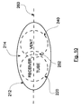
- FIG. 10 is a drawing of the tip surface
- FIG. 11 is a partial cross-sectional view of a hearing instrument shell comprising a receiver tube and a vent having a cylindrical section of reduced diameter;
- FIGS. 12-15 are flow charts of processes for manufacturing the hearing instrument.
- FIGS. 16-20 illustrate an arrangement for accommodating a wax guard.
- FIG. 1 illustrates a hearing instrument, which has an outer shell or housing 10 positioned as least partially in the ear canal, adjacent the walls 20 of the canal of the person wearing the hearing instrument.
- the hearing instrument shell 10 has a tip 12 —the section of the shell 10 inserted into the ear canal—oriented towards the inner ear and a faceplate 14 oriented towards the outer ear.
- FIG. 2 illustrates a partial cross-sectional view of the hearing instrument shell 10 .
- the only parts of the hearing instrument shown in this figure are the receiver tube 100 , the vent 120 , and a portion of the shell 10 .
- the vent 120 may be fabricated as a channel on the inside wall of the shell 10 , but is shown here as a cylindrical object.
- the vent could be realized as a separate tube similar to the receiver tube 100 .
- the receiver tube 100 exits the shell 10 at a receiver tube hole 102 and the vent 120 has a port at a vent hole 122 .
- the tip 12 of the shell 10 has sufficient area to accommodate openings (i.e., the receiver tube hole 102 and the vent hole 122 ) for the full circumferences of the respective receiver tube 100 and the vent 120 , as well as sufficient volume within the tip 12 for the receiver tube 100 and the vent 120 .
- the receiver tube 100 and the vent 120 are immediately adjacent one another. If hearing instrument tip 12 , there would not be sufficient room to position the receiver tube 100 and the vent 120 side-by-side, as well as provide openings for the full circumferences of the receiver tube and the vent, without interference.
- FIGS. 3 and 4 An arrangement illustrating a smaller shell tip 212 is shown in FIGS. 3 and 4 .
- the housing or shell 10 comprises a receiver tube 220 and a vent 240
- the end region or shell tip surface 214 of the shell tip 212 comprises a receiver tube hole 222 and a vent hole 242 .
- the vent 240 has a reduced cross-section in the vicinity of the shell tip 212 where it is adjacent the receiver tube 220 .
- a cutaway section or taper 250 has been applied to the vent 240 near the shell tip 212 .
- the vent hole 242 similarly requires less surface area on the shell tip surface 214 and its shape conforms to the tapered outline of the vent 240 where it intersects the shell tip 212 .
- the vent 240 is tapered only for a short distance and resumes its otherwise full circumference or cross-section below the shell tip 212 where the full cross-section of the vent 240 would no longer interfere with the receiver tube 220 .
- the taper 250 begins inside the shell 200 at the point 224 where the receiver tube 220 first meets the vent 240 and continues as the vent 240 narrows until the shell tip surface 214 is reached, where the receiver tube 220 terminates in the receiver tube hole 222 , and the vent 240 terminates in the vent hole 242 .
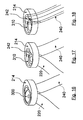
- FIGS. 5-7 illustrate a process for creating the taper in the vent 240 .
- a portion of the vent 240 is removed using the surface 226 of the receiver tube 220 as a cutting tool, leaving a cutaway section or taper 250 .
- the receiver tube 220 is then positioned against the vent 240 at the location where the material has been removed, as illustrated in FIG. 7 .
- this process could be achieved by fabricating a vent with a reduced cross-section or taper already in place and thus not requiring a machining or cutting operation.
- the surface 246 of the vent 240 in the region of the cutaway section 250 may be reconstructed with a wall section 252 , as illustrated in FIG. 8 .
- the wall section 252 may be concave and can be created using the Boolean intersection of the surface 226 of the receiver tube 220 and the surface 246 of the vent 240 .
- Depth i.e., thickness
- the wall section 252 can be fabricated directly as part of the vent 240 using rapid prototyping or direct manufacturing techniques.
- the wall section 252 seals the vent 240 and prevents sound from leaking where the receiver tube 220 would otherwise adjoin the vent 240 . Instead, the receiver tube 220 and the wall section 252 sit adjacent each other as shown in FIG. 9 .
- the receiver tube 220 could be tapered, or both the vent 240 and the receiver tube 220 could be tapered.
- the reduction in cross section of either the receiver tube 220 or the vent 240 could be achieved without applying the taper or shape conforming to the receiver tube 220 shown in FIGS. 3-9 .
- the vent 240 could have a cylindrical section 270 of reduced diameter in the area between the vent hole 242 and the point in space ( 224 ) where the vent 240 and the receiver tube 220 would not physically interfere.
- the hearing instrument shell 10 is modeled in virtual space, using well-known computer-aided design (CAD) tools, including Boolean modeling operations.
- CAD computer-aided design
- the shell tip surface 214 of the shell tip 212 may be roughly elliptical in shape.
- the centers of the receiver tube 220 and the vent 240 can be positioned on the major axis 260 of the shell tip surface 214 . If the receiver tube 220 and vent 240 do not interfere with each other, as is the case in FIG. 2 , then no modification is required of either.
- the vent tube hole 242 and the vent 240 can be trimmed (or tapered) to accommodate the receiver tube hole 222 and the receiver tube 220 . Therefore, in this arrangement, the dimensions of the receiver tube 220 and the receiver tube hole 222 are protected, maintaining their full cross-sections.
- the location of the vent 240 and the vent hole 242 are fixed.
- the location of the receiver tube hole 222 is then determined.
- a Boolean subtraction operation may be performed on the vent tube 240 and the vent hole 242 , removing material from both.
- a wall 252 of predetermined thickness may be added to the vent 220 .
- a Boolean intersection operation may be used to generate the outer surface 254 of the wall 252 . By “growing” the wall 252 inwardly (i.e., towards the interior 244 of the vent 240 proper), the wall 252 is given a desired thickness.
- the receiver tube hole 222 and receiver tube 220 positions could be fixed, as outlined in the flow chart of FIG. 14 . Then, the respective locations and positions of the vent hole 242 and vent 240 would be determined and moved into place using a Boolean subtraction based on the surface of the receiver tube 220 . Finally, a wall 252 can be added if desired.
- the flow chart of FIG. 15 offers a third method of locating the receiver tube and vent holes.
- the locations of both the receiver tube hole 222 and the vent hole 242 are selected at the same time, adjusting them as necessary to provide the desired size for the vent hole 242 .
- the surface of the receiver tube 220 is used to perform a Boolean subtraction of the interfering portion of the vent 240 .
- a wall 252 may be added based on the Boolean intersection of the receiver tube 220 and the vent 240 .
- FIGS. 16-20 illustrate an arrangement for accommodating a wax guard 300 in a recess 310 provided in the tip surface 214 of the hearing instrument shell 10 .
- the recess 310 is located where the receiver tube hole 222 would be positioned in the shell tip 12 .
- the receiver tube 220 in this instance would terminate at the recess 310 .
- the Boolean methods could be employed to remove material from the vent hole 242 that would be in the space occupied by the wax guard (see, e.g., FIGS. 17-19 ).
Abstract
Description
Claims (9)
Priority Applications (1)
| Application Number | Priority Date | Filing Date | Title |
|---|---|---|---|
| US11/386,063 US8096383B2 (en) | 2006-03-21 | 2006-03-21 | Tapered vent for a hearing instrument |
Applications Claiming Priority (1)
| Application Number | Priority Date | Filing Date | Title |
|---|---|---|---|
| US11/386,063 US8096383B2 (en) | 2006-03-21 | 2006-03-21 | Tapered vent for a hearing instrument |
Publications (2)
| Publication Number | Publication Date |
|---|---|
| US20070223757A1 US20070223757A1 (en) | 2007-09-27 |
| US8096383B2 true US8096383B2 (en) | 2012-01-17 |
Family
ID=38533483
Family Applications (1)
| Application Number | Title | Priority Date | Filing Date |
|---|---|---|---|
| US11/386,063 Active 2030-04-24 US8096383B2 (en) | 2006-03-21 | 2006-03-21 | Tapered vent for a hearing instrument |
Country Status (1)
| Country | Link |
|---|---|
| US (1) | US8096383B2 (en) |
Cited By (7)
| Publication number | Priority date | Publication date | Assignee | Title |
|---|---|---|---|---|
| US20090123010A1 (en) * | 2005-08-01 | 2009-05-14 | Gn Resound A/S | Hearing device with an open earpiece having a short vent |
| US20090310805A1 (en) * | 2008-06-14 | 2009-12-17 | Michael Petroff | Hearing aid with anti-occlusion effect techniques and ultra-low frequency response |
| US10869141B2 (en) | 2018-01-08 | 2020-12-15 | Knowles Electronics, Llc | Audio device with valve state management |
| US10917731B2 (en) | 2018-12-31 | 2021-02-09 | Knowles Electronics, Llc | Acoustic valve for hearing device |
| US10932069B2 (en) | 2018-04-12 | 2021-02-23 | Knowles Electronics, Llc | Acoustic valve for hearing device |
| US10939217B2 (en) | 2017-12-29 | 2021-03-02 | Knowles Electronics, Llc | Audio device with acoustic valve |
| US11102576B2 (en) | 2018-12-31 | 2021-08-24 | Knowles Electronicis, LLC | Audio device with audio signal processing based on acoustic valve state |
Families Citing this family (1)
| Publication number | Priority date | Publication date | Assignee | Title |
|---|---|---|---|---|
| US8494814B2 (en) | 2009-11-02 | 2013-07-23 | Siemens Corporation | Methods for inlet and outlet modelling of vent as large as possible for hearing aid devices |
Citations (48)
| Publication number | Priority date | Publication date | Assignee | Title |
|---|---|---|---|---|
| US2312534A (en) * | 1942-02-11 | 1943-03-02 | Henry D Flene | Acoustic device |
| US3368644A (en) * | 1966-03-28 | 1968-02-13 | John D. Henderson | Hearing aid tone tuning device and method |
| US3470328A (en) * | 1966-03-02 | 1969-09-30 | Goldentone Electronics Inc | Hearing aid vent tube |
| US3702123A (en) * | 1971-09-09 | 1972-11-07 | John T Macken | Vented hearing aid ear mold |
| US4069400A (en) * | 1977-01-31 | 1978-01-17 | United States Surgical Corporation | Modular in-the-ear hearing aid |
| US4375016A (en) * | 1980-04-28 | 1983-02-22 | Qualitone Hearing Aids Inc. | Vented ear tip for hearing aid and adapter coupler therefore |
| US4442917A (en) * | 1981-01-19 | 1984-04-17 | Johnson Rubein V | Vented acoustic ear mold for hearing aids |
| US4532649A (en) * | 1983-07-03 | 1985-07-30 | Gaspare Bellafiore | Hearing aid |
| US4712245A (en) * | 1985-01-24 | 1987-12-08 | Oticon Electronics A/S | In-the-ear hearing aid with the outer wall formed by rupturing a two-component chamber |
| US4729451A (en) * | 1984-05-30 | 1988-03-08 | Beltone Electronics, Corporation | Receiver suspension and acoustic porting system |
| US4811402A (en) * | 1986-11-13 | 1989-03-07 | Epic Corporation | Method and apparatus for reducing acoustical distortion |
| US4852177A (en) * | 1986-08-28 | 1989-07-25 | Sensesonics, Inc. | High fidelity earphone and hearing aid |
| US4870688A (en) * | 1986-05-27 | 1989-09-26 | Barry Voroba | Mass production auditory canal hearing aid |
| US4879750A (en) * | 1984-12-15 | 1989-11-07 | Siemens Aktiengesellschaft | Hearing aid with cerumen trapping gap |
| US4878560A (en) * | 1989-03-16 | 1989-11-07 | Scott Robert T | Earmold |
| US4974606A (en) * | 1988-03-17 | 1990-12-04 | Safetec S.A. | Hearing protector and method of manufacturing the same |
| US5068902A (en) * | 1986-11-13 | 1991-11-26 | Epic Corporation | Method and apparatus for reducing acoustical distortion |
| WO1992003894A1 (en) * | 1990-08-20 | 1992-03-05 | Minnesota Mining And Manufacturing Company | Hearing aid and method for preparing same |
| US5099947A (en) * | 1990-09-04 | 1992-03-31 | Starkey Laboratories, Inc. | Wax guard for hearing aids |
| CH681125A5 (en) * | 1990-07-20 | 1993-01-15 | Phonak Ag | Ventilated in-ear hearing aid - has openings in opposite end faces of housing saving wearer from unpleasant ear plug feeling |
| US5195139A (en) * | 1991-05-15 | 1993-03-16 | Ensoniq Corporation | Hearing aid |
| US5278360A (en) * | 1991-09-26 | 1994-01-11 | Unitron Industries Ltd. | Hearing aid wax guard with integral bridge |
| US5327500A (en) * | 1992-12-21 | 1994-07-05 | Campbell Donald E K | Cerumen barrier for custom in the ear type hearing intruments |
| US5535282A (en) * | 1994-05-27 | 1996-07-09 | Ermes S.R.L. | In-the-ear hearing aid |
| US5875254A (en) * | 1997-12-18 | 1999-02-23 | Siemens Hearing Instruments, Inc. | Binaural hearing aid with integrated retrieval line and microphone |
| US6105713A (en) * | 1998-09-17 | 2000-08-22 | Sonic Innovations, Inc. | Cover movable by rotation forming a cerumen barrier in a hearing aid |
| US6249587B1 (en) * | 1996-07-24 | 2001-06-19 | Bernafon Ag | Hearing aid to be worn completely in the auditory canal and individualized by a cast body |
| US6339648B1 (en) * | 1999-03-26 | 2002-01-15 | Sonomax (Sft) Inc | In-ear system |
| US6359993B2 (en) * | 1999-01-15 | 2002-03-19 | Sonic Innovations | Conformal tip for a hearing aid with integrated vent and retrieval cord |
| US20020136420A1 (en) * | 2001-03-26 | 2002-09-26 | Jan Topholm | Hearing aid with a face plate that is automatically manufactured to fit the hearing aid shell |
| US20020196954A1 (en) * | 2001-06-22 | 2002-12-26 | Marxen Christopher J. | Modeling and fabrication of three-dimensional irregular surfaces for hearing instruments |
| US6549635B1 (en) * | 1999-09-07 | 2003-04-15 | Siemens Audiologische Technik Gmbh | Hearing aid with a ventilation channel that is adjustable in cross-section |
| US20030074174A1 (en) * | 2000-10-06 | 2003-04-17 | Ping Fu | Manufacturing methods and systems for rapid production of hearing-aid shells |
| US6661901B1 (en) * | 2000-09-01 | 2003-12-09 | Nacre As | Ear terminal with microphone for natural voice rendition |
| US6728383B1 (en) * | 1997-12-18 | 2004-04-27 | Softear Technologies, L.L.C. | Method of compensating for hearing loss |
| US20040107080A1 (en) * | 2001-03-02 | 2004-06-03 | Nikolaj Deichmann | Method for modelling customised earpieces |
| US6754359B1 (en) * | 2000-09-01 | 2004-06-22 | Nacre As | Ear terminal with microphone for voice pickup |
| US20040218772A1 (en) * | 2003-04-03 | 2004-11-04 | Ryan James G. | Hearing instrument vent |
| US6819770B2 (en) * | 2001-08-27 | 2004-11-16 | Siemens Audiologische Technik Gmbh | Hearing aid with portion thereof inserted in auditory canal, with auditory canal ventilation |
| US20050141739A1 (en) * | 2003-02-28 | 2005-06-30 | Softear Technologies, L.L.C. (A Louisiana Limited Liability Company) | Soft hearing aid with stainless steel wire |
| US20050286731A1 (en) * | 1998-11-25 | 2005-12-29 | Adnan Shennib | Inconspicuous semi-permanent hearing device |
| US20060045297A1 (en) * | 2004-08-25 | 2006-03-02 | Phonak Ag | Earplug and method for manufacturing the same |
| US7025061B2 (en) * | 2004-08-25 | 2006-04-11 | Phonak Ag | Customized passive hearing protection earplug, use of the same and method for manufacturing the same |
| US7079662B2 (en) * | 2002-02-06 | 2006-07-18 | Siemens Audiologische Technik Gmbh | Hearing aid device wearable in the ear or hearing aid device having an otoplastic wearable in the ear |
| US20070003085A1 (en) * | 2005-07-01 | 2007-01-04 | Phonak Ag | In-ear device |
| US20070206826A1 (en) * | 2006-02-21 | 2007-09-06 | Siemens Audiologische Technik Gmbh | In-the ear hearing aid device with a vent |
| US20080118095A1 (en) * | 2006-11-22 | 2008-05-22 | Fletcher Thomas G | Wax guard for a hearing aid |
| US7401680B2 (en) * | 2004-12-23 | 2008-07-22 | Phonak Ag | Hearing protection earplug and use of the same |
-
2006
- 2006-03-21 US US11/386,063 patent/US8096383B2/en active Active
Patent Citations (49)
| Publication number | Priority date | Publication date | Assignee | Title |
|---|---|---|---|---|
| US2312534A (en) * | 1942-02-11 | 1943-03-02 | Henry D Flene | Acoustic device |
| US3470328A (en) * | 1966-03-02 | 1969-09-30 | Goldentone Electronics Inc | Hearing aid vent tube |
| US3368644A (en) * | 1966-03-28 | 1968-02-13 | John D. Henderson | Hearing aid tone tuning device and method |
| US3702123A (en) * | 1971-09-09 | 1972-11-07 | John T Macken | Vented hearing aid ear mold |
| US4069400A (en) * | 1977-01-31 | 1978-01-17 | United States Surgical Corporation | Modular in-the-ear hearing aid |
| US4375016A (en) * | 1980-04-28 | 1983-02-22 | Qualitone Hearing Aids Inc. | Vented ear tip for hearing aid and adapter coupler therefore |
| US4442917A (en) * | 1981-01-19 | 1984-04-17 | Johnson Rubein V | Vented acoustic ear mold for hearing aids |
| US4532649A (en) * | 1983-07-03 | 1985-07-30 | Gaspare Bellafiore | Hearing aid |
| US4729451A (en) * | 1984-05-30 | 1988-03-08 | Beltone Electronics, Corporation | Receiver suspension and acoustic porting system |
| US4879750A (en) * | 1984-12-15 | 1989-11-07 | Siemens Aktiengesellschaft | Hearing aid with cerumen trapping gap |
| US4712245A (en) * | 1985-01-24 | 1987-12-08 | Oticon Electronics A/S | In-the-ear hearing aid with the outer wall formed by rupturing a two-component chamber |
| US4870688A (en) * | 1986-05-27 | 1989-09-26 | Barry Voroba | Mass production auditory canal hearing aid |
| US4852177A (en) * | 1986-08-28 | 1989-07-25 | Sensesonics, Inc. | High fidelity earphone and hearing aid |
| US4811402A (en) * | 1986-11-13 | 1989-03-07 | Epic Corporation | Method and apparatus for reducing acoustical distortion |
| US5068902A (en) * | 1986-11-13 | 1991-11-26 | Epic Corporation | Method and apparatus for reducing acoustical distortion |
| US4974606A (en) * | 1988-03-17 | 1990-12-04 | Safetec S.A. | Hearing protector and method of manufacturing the same |
| US4878560A (en) * | 1989-03-16 | 1989-11-07 | Scott Robert T | Earmold |
| CH681125A5 (en) * | 1990-07-20 | 1993-01-15 | Phonak Ag | Ventilated in-ear hearing aid - has openings in opposite end faces of housing saving wearer from unpleasant ear plug feeling |
| WO1992003894A1 (en) * | 1990-08-20 | 1992-03-05 | Minnesota Mining And Manufacturing Company | Hearing aid and method for preparing same |
| US5321757A (en) * | 1990-08-20 | 1994-06-14 | Minnesota Mining And Manufacturing Company | Hearing aid and method for preparing same |
| US5099947A (en) * | 1990-09-04 | 1992-03-31 | Starkey Laboratories, Inc. | Wax guard for hearing aids |
| US5195139A (en) * | 1991-05-15 | 1993-03-16 | Ensoniq Corporation | Hearing aid |
| US5278360A (en) * | 1991-09-26 | 1994-01-11 | Unitron Industries Ltd. | Hearing aid wax guard with integral bridge |
| US5327500A (en) * | 1992-12-21 | 1994-07-05 | Campbell Donald E K | Cerumen barrier for custom in the ear type hearing intruments |
| US5535282A (en) * | 1994-05-27 | 1996-07-09 | Ermes S.R.L. | In-the-ear hearing aid |
| US6249587B1 (en) * | 1996-07-24 | 2001-06-19 | Bernafon Ag | Hearing aid to be worn completely in the auditory canal and individualized by a cast body |
| US5875254A (en) * | 1997-12-18 | 1999-02-23 | Siemens Hearing Instruments, Inc. | Binaural hearing aid with integrated retrieval line and microphone |
| US6728383B1 (en) * | 1997-12-18 | 2004-04-27 | Softear Technologies, L.L.C. | Method of compensating for hearing loss |
| US6105713A (en) * | 1998-09-17 | 2000-08-22 | Sonic Innovations, Inc. | Cover movable by rotation forming a cerumen barrier in a hearing aid |
| US20050286731A1 (en) * | 1998-11-25 | 2005-12-29 | Adnan Shennib | Inconspicuous semi-permanent hearing device |
| US6359993B2 (en) * | 1999-01-15 | 2002-03-19 | Sonic Innovations | Conformal tip for a hearing aid with integrated vent and retrieval cord |
| US6339648B1 (en) * | 1999-03-26 | 2002-01-15 | Sonomax (Sft) Inc | In-ear system |
| US6549635B1 (en) * | 1999-09-07 | 2003-04-15 | Siemens Audiologische Technik Gmbh | Hearing aid with a ventilation channel that is adjustable in cross-section |
| US6661901B1 (en) * | 2000-09-01 | 2003-12-09 | Nacre As | Ear terminal with microphone for natural voice rendition |
| US6754359B1 (en) * | 2000-09-01 | 2004-06-22 | Nacre As | Ear terminal with microphone for voice pickup |
| US20030074174A1 (en) * | 2000-10-06 | 2003-04-17 | Ping Fu | Manufacturing methods and systems for rapid production of hearing-aid shells |
| US20040107080A1 (en) * | 2001-03-02 | 2004-06-03 | Nikolaj Deichmann | Method for modelling customised earpieces |
| US20020136420A1 (en) * | 2001-03-26 | 2002-09-26 | Jan Topholm | Hearing aid with a face plate that is automatically manufactured to fit the hearing aid shell |
| US20020196954A1 (en) * | 2001-06-22 | 2002-12-26 | Marxen Christopher J. | Modeling and fabrication of three-dimensional irregular surfaces for hearing instruments |
| US6819770B2 (en) * | 2001-08-27 | 2004-11-16 | Siemens Audiologische Technik Gmbh | Hearing aid with portion thereof inserted in auditory canal, with auditory canal ventilation |
| US7079662B2 (en) * | 2002-02-06 | 2006-07-18 | Siemens Audiologische Technik Gmbh | Hearing aid device wearable in the ear or hearing aid device having an otoplastic wearable in the ear |
| US20050141739A1 (en) * | 2003-02-28 | 2005-06-30 | Softear Technologies, L.L.C. (A Louisiana Limited Liability Company) | Soft hearing aid with stainless steel wire |
| US20040218772A1 (en) * | 2003-04-03 | 2004-11-04 | Ryan James G. | Hearing instrument vent |
| US20060045297A1 (en) * | 2004-08-25 | 2006-03-02 | Phonak Ag | Earplug and method for manufacturing the same |
| US7025061B2 (en) * | 2004-08-25 | 2006-04-11 | Phonak Ag | Customized passive hearing protection earplug, use of the same and method for manufacturing the same |
| US7401680B2 (en) * | 2004-12-23 | 2008-07-22 | Phonak Ag | Hearing protection earplug and use of the same |
| US20070003085A1 (en) * | 2005-07-01 | 2007-01-04 | Phonak Ag | In-ear device |
| US20070206826A1 (en) * | 2006-02-21 | 2007-09-06 | Siemens Audiologische Technik Gmbh | In-the ear hearing aid device with a vent |
| US20080118095A1 (en) * | 2006-11-22 | 2008-05-22 | Fletcher Thomas G | Wax guard for a hearing aid |
Cited By (8)
| Publication number | Priority date | Publication date | Assignee | Title |
|---|---|---|---|---|
| US20090123010A1 (en) * | 2005-08-01 | 2009-05-14 | Gn Resound A/S | Hearing device with an open earpiece having a short vent |
| US8792663B2 (en) * | 2005-08-01 | 2014-07-29 | Gn Resound A/S | Hearing device with an open earpiece having a short vent |
| US20090310805A1 (en) * | 2008-06-14 | 2009-12-17 | Michael Petroff | Hearing aid with anti-occlusion effect techniques and ultra-low frequency response |
| US10939217B2 (en) | 2017-12-29 | 2021-03-02 | Knowles Electronics, Llc | Audio device with acoustic valve |
| US10869141B2 (en) | 2018-01-08 | 2020-12-15 | Knowles Electronics, Llc | Audio device with valve state management |
| US10932069B2 (en) | 2018-04-12 | 2021-02-23 | Knowles Electronics, Llc | Acoustic valve for hearing device |
| US10917731B2 (en) | 2018-12-31 | 2021-02-09 | Knowles Electronics, Llc | Acoustic valve for hearing device |
| US11102576B2 (en) | 2018-12-31 | 2021-08-24 | Knowles Electronicis, LLC | Audio device with audio signal processing based on acoustic valve state |
Also Published As
| Publication number | Publication date |
|---|---|
| US20070223757A1 (en) | 2007-09-27 |
Similar Documents
| Publication | Publication Date | Title |
|---|---|---|
| US8096383B2 (en) | Tapered vent for a hearing instrument | |
| EP1880699B1 (en) | Method for manufacturing an earplug | |
| US9277336B2 (en) | Vented dome | |
| US7369670B2 (en) | Earplug and method for manufacturing the same | |
| US20020196954A1 (en) | Modeling and fabrication of three-dimensional irregular surfaces for hearing instruments | |
| US7240765B2 (en) | Customized hearing protection earplug with an acoustic filter and method for manufacturing the same | |
| EP2206358B1 (en) | In-ear digital electronic noise cancelling and communication device | |
| EP2986029A1 (en) | Method and system for modeling a custom fit earmold | |
| US7025061B2 (en) | Customized passive hearing protection earplug, use of the same and method for manufacturing the same | |
| JP4674032B2 (en) | Manufacturing method for ear device | |
| ES2653214T3 (en) | Procedure and system to create non-occlusive headphones | |
| WO2002030157A3 (en) | Manufacturing methods and systems for rapid production of hearing-aid shells | |
| CN110800318A (en) | Custom earplug | |
| US20060042867A1 (en) | Hearing protection earplug and method for manufacturing such an earplug | |
| JP2012510222A (en) | Hearing aid earpiece and method of manufacturing a hearing aid earpiece | |
| EP2083583A1 (en) | Fabrication of a soft-silicone cover for a hearing instrument shell | |
| US8554352B2 (en) | Method of generating an optimized venting channel in a hearing instrument | |
| US20200186905A1 (en) | In-ear housing with customized retention | |
| US20080089542A1 (en) | Acoustic enhancement for behind the ear communication devices | |
| EP2048895B1 (en) | A computerized rule-based binaural modeling system and method for hearing aid design | |
| WO2021096873A1 (en) | Construction techniques for hearing instruments | |
| PL214681B1 (en) | A method of forming an earplug by laser ablation and an earplug formed thereby | |
| CN202276464U (en) | Deep ear canal hearing apparatus | |
| JP2020184746A (en) | Hearing device having vent | |
| JP2009200670A (en) | Ear wax invasion preventing chip and hearing aid |
Legal Events
| Date | Code | Title | Description |
|---|---|---|---|
| AS | Assignment |
Owner name: SIEMENS HEARING INSTRUMENTS INC., NEW JERSEY Free format text: ASSIGNMENT OF ASSIGNORS INTEREST;ASSIGNORS:SALTYKOV, OLEG;MCBAGONLURI, FRED;REEL/FRAME:017591/0587 Effective date: 20060501 |
|
| STCF | Information on status: patent grant |
Free format text: PATENTED CASE |
|
| FPAY | Fee payment |
Year of fee payment: 4 |
|
| AS | Assignment |
Owner name: SIVANTOS, INC., NEW JERSEY Free format text: CHANGE OF NAME;ASSIGNOR:SIEMENS HEARING INSTRUMENTS, INC.;REEL/FRAME:036092/0609 Effective date: 20150213 |
|
| MAFP | Maintenance fee payment |
Free format text: PAYMENT OF MAINTENANCE FEE, 8TH YEAR, LARGE ENTITY (ORIGINAL EVENT CODE: M1552); ENTITY STATUS OF PATENT OWNER: LARGE ENTITY Year of fee payment: 8 |
|
| MAFP | Maintenance fee payment |
Free format text: PAYMENT OF MAINTENANCE FEE, 12TH YEAR, LARGE ENTITY (ORIGINAL EVENT CODE: M1553); ENTITY STATUS OF PATENT OWNER: LARGE ENTITY Year of fee payment: 12 |