US8104811B2 - Stick operable hooking device - Google Patents
Stick operable hooking device Download PDFInfo
- Publication number
- US8104811B2 US8104811B2 US12/449,210 US44921008A US8104811B2 US 8104811 B2 US8104811 B2 US 8104811B2 US 44921008 A US44921008 A US 44921008A US 8104811 B2 US8104811 B2 US 8104811B2
- Authority
- US
- United States
- Prior art keywords
- elongated member
- hooking
- head
- hooking device
- sliding
- Prior art date
- Legal status (The legal status is an assumption and is not a legal conclusion. Google has not performed a legal analysis and makes no representation as to the accuracy of the status listed.)
- Expired - Fee Related, expires
Links
- 230000004044 response Effects 0.000 claims abstract description 6
- 239000011248 coating agent Substances 0.000 claims description 7
- 238000000576 coating method Methods 0.000 claims description 6
- 238000005452 bending Methods 0.000 claims description 4
- 230000001747 exhibiting effect Effects 0.000 claims description 4
- 230000000295 complement effect Effects 0.000 claims description 3
- 230000003247 decreasing effect Effects 0.000 claims description 2
- 239000006096 absorbing agent Substances 0.000 description 6
- 241001125879 Gobio Species 0.000 description 4
- 238000009434 installation Methods 0.000 description 3
- 239000000463 material Substances 0.000 description 3
- 206010014405 Electrocution Diseases 0.000 description 2
- 230000009194 climbing Effects 0.000 description 2
- 230000008878 coupling Effects 0.000 description 2
- 238000010168 coupling process Methods 0.000 description 2
- 238000005859 coupling reaction Methods 0.000 description 2
- 239000007787 solid Substances 0.000 description 2
- 239000002023 wood Substances 0.000 description 2
- 208000012661 Dyskinesia Diseases 0.000 description 1
- 239000002131 composite material Substances 0.000 description 1
- 238000010276 construction Methods 0.000 description 1
- 230000000694 effects Effects 0.000 description 1
- 238000010616 electrical installation Methods 0.000 description 1
- 238000010292 electrical insulation Methods 0.000 description 1
- 239000000835 fiber Substances 0.000 description 1
- 239000011152 fibreglass Substances 0.000 description 1
- 238000003780 insertion Methods 0.000 description 1
- 230000037431 insertion Effects 0.000 description 1
- 238000007689 inspection Methods 0.000 description 1
- 239000012212 insulator Substances 0.000 description 1
- 238000012986 modification Methods 0.000 description 1
- 230000004048 modification Effects 0.000 description 1
- 230000017311 musculoskeletal movement, spinal reflex action Effects 0.000 description 1
- 230000035515 penetration Effects 0.000 description 1
- 230000000452 restraining effect Effects 0.000 description 1
- 210000000162 simple eye Anatomy 0.000 description 1
- 230000003068 static effect Effects 0.000 description 1
- 238000005728 strengthening Methods 0.000 description 1
- 239000002966 varnish Substances 0.000 description 1
- 125000000391 vinyl group Chemical group [H]C([*])=C([H])[H] 0.000 description 1
- 229920002554 vinyl polymer Polymers 0.000 description 1
Images


Classifications
-
- A—HUMAN NECESSITIES
- A62—LIFE-SAVING; FIRE-FIGHTING
- A62B—DEVICES, APPARATUS OR METHODS FOR LIFE-SAVING
- A62B99/00—Subject matter not provided for in other groups of this subclass
-
- F—MECHANICAL ENGINEERING; LIGHTING; HEATING; WEAPONS; BLASTING
- F16—ENGINEERING ELEMENTS AND UNITS; GENERAL MEASURES FOR PRODUCING AND MAINTAINING EFFECTIVE FUNCTIONING OF MACHINES OR INSTALLATIONS; THERMAL INSULATION IN GENERAL
- F16B—DEVICES FOR FASTENING OR SECURING CONSTRUCTIONAL ELEMENTS OR MACHINE PARTS TOGETHER, e.g. NAILS, BOLTS, CIRCLIPS, CLAMPS, CLIPS OR WEDGES; JOINTS OR JOINTING
- F16B45/00—Hooks; Eyes
- F16B45/02—Hooks with pivoting or elastically bending closing member
- F16B45/023—Hooks with pivoting or elastically bending closing member the closing member pivoting about an axis perpendicular to the plane of the hook
-
- Y—GENERAL TAGGING OF NEW TECHNOLOGICAL DEVELOPMENTS; GENERAL TAGGING OF CROSS-SECTIONAL TECHNOLOGIES SPANNING OVER SEVERAL SECTIONS OF THE IPC; TECHNICAL SUBJECTS COVERED BY FORMER USPC CROSS-REFERENCE ART COLLECTIONS [XRACs] AND DIGESTS
- Y10—TECHNICAL SUBJECTS COVERED BY FORMER USPC
- Y10T—TECHNICAL SUBJECTS COVERED BY FORMER US CLASSIFICATION
- Y10T24/00—Buckles, buttons, clasps, etc.
- Y10T24/45—Separable-fastener or required component thereof [e.g., projection and cavity to complete interlock]
- Y10T24/45225—Separable-fastener or required component thereof [e.g., projection and cavity to complete interlock] including member having distinct formations and mating member selectively interlocking therewith
- Y10T24/45272—Projection passes through cavity then moves toward noninserted portion of its member to complete interlock [e.g., snap hook]
- Y10T24/45288—Hook type projection member
- Y10T24/45304—Noninserted portion of projection member includes movably connected gate for closing access throat
- Y10T24/45382—Track or way guided gate
- Y10T24/45387—Track or way guided gate having means biasing gate
- Y10T24/45398—Cavity in shank forms track or way
Definitions
- the invention relates to a stick operable hooking device for attaching equipment like a fall limiter to an anchorage structural element, as used for safety purposes by a worker having to perform works high up.
- the hooking device may also be used for any application requiring hanging up an equipment, for example a rope, an apparatus, from a distance or high up by means of a stick.
- One possible equipment consists of a harness worn by the worker and a strap system attached to the harness, allowing to form a restraining loop or belt around the pole.
- the loop tightens around the pole and prevents the free fall of the worker.
- grapples can be added to the strap system. The grapples however reduce the mobility of the workers on pole. Furthermore, the crossing of obstacles such as telephone or cable line cables forces the worker to perform many buckle-unbuckle movements of the strap system so that he/she is always fastened in accordance with safety standards.
- Another possible equipment used or not in complement to the aforesaid equipment, consists of a fall limiter used to limit the effort of an eventual fall to an acceptable level on the body of the worker. It comprises an anchorage point, a harness worn by the worker, and an anti-fall linking system.
- the linking system can take the form of a glider on a rope (commonly called lifeline), a lanyard with an energy absorber, a reel.
- lifeline commonly called lifeline
- One problem with the current anti-fall linking systems resides in finding an appropriate anchorage point on the work structure.
- Another problem resides in attaching the linking system to the structural element providing the anchorage point located in general high up.
- another problem resides in eliminating or else reducing the possible electrocution dangers.
- An object of the present invention is to provide a stick operable hooking device for attaching an equipment, like a fall limiter, to an anchorage point.
- Another object of the present invention is to provide a hooking device having a weight allowing manipulating and operating it at the end of a stick of many feet, for example forty feet.
- Another object of the present invention is to provide a hooking device that may be attached to various structural elements providing anchorage points, in particular a transformer bracket, a stop bolt, a brace.
- Another object of the present invention is to provide a hooking device that can support a load effort of many kilonewtons depending on the equipment used or the expected use, for example 12 kN, 18 kN, 22.5 kN, or more.
- Another object of the present invention is to provide a hooking device that can unhook only by appropriate operation from the user when it is set in position.
- Another object of the present invention is to provide a hooking device having a reliable functioning over en extended range of temperature and conditions of use.
- Another object of the present invention is to provide a hooking device that can exhibit insulating properties reducing electrocution risks when used near live electrical lines.
- a hooking device for attaching an equipment to an anchorage structural element by means of a stick, comprising:
- FIG. 1 is a perspective view of a stick operable hooking device.
- FIG. 2 is an exploded perspective view of a hooking device and an end of a stick for operating it.
- FIGS. 3 , 4 and 5 are side views of a hooking device, in closed position, opened position and during opening or closing.
- FIG. 6 is a front view of a hooking device.
- FIG. 7 is a cross-section view taken along line 7 - 7 in FIG. 6 .
- FIGS. 8 , 9 and 10 are side, top and rear views of a hooking head of a hooking device.
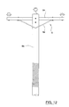
- FIG. 11 is a side view of a hooking device mounted at the end of a stick and to which a fall limiter is attached.
- FIGS. 12 , 13 and 14 are views of structures to which the hooking device can be hooked.
- the hooking device 2 is designed for attaching an equipment like a fall limiter 4 to an anchorage structural element 6 (see for example in FIGS. 12 , 13 and 14 ) by means of a stick 8 .
- the fall limiter 4 is of “lifeline” type and is made of a strap 10 that can be arranged for use as a fall indicator, a rope 12 forming the “lifeline”, and a lanyard 14 provided with a hook 16 intended to be fastened to the worker, for example to a harness or belt worn by the worker.
- the lanyard 14 may be provided with an energy absorber 15 .
- a glider 18 allows the lanyard 14 to glide along the rope 12 and comprises a stop mechanism adjusted to arrest the gliding should the worker fall.
- the hooking device 2 may well be used with other types of fall limiters, for example with a reel or self-retractor (not shown), equipped with or deprived of energy absorbers.
- the hooking device 2 may also be used for attaching other kinds of equipment from a distance by means of a stick, for example a tool, a simple rope, a chain, an apparatus, etc.
- the hooking device 2 comprises an elongated member 20 having lower and upper ends 22 , 24 .
- the hooking device 2 also comprises an attachment element 26 for attaching the fall limiter 4 to the lower end 22 of the elongated member 20 .
- the attachment element 26 may be made of a simple eye 28 extending through the elongated member 20 between opposite faces of the elongated member 20 , for allowing passage of the strap 10 , a snap hook (not shown) or any other fastener able to pass in the eye 28 .
- the eye 28 may exhibit chamfered openings on each one of the opposite faces of the elongated member 20 to limit the possible wear of the strap 10 .
- the eye 28 may be disposed near the lower end 22 of the elongated member 20 such as illustrated, so as to be well clear and that the weight of the lifeline has a lever effect for maintaining the elongated member 20 in axis close to vertical.
- the eye 28 may also be disposed farther from the end if desired.
- the elongated member 20 is straight and rectangular with rounded ends, but it may also be bent and exhibit projecting or recessed portions with respect to its longitudinal axis.
- a lower arm 40 of the elongated member 20 may have opposite faces exhibiting longitudinal recesses 38 that may contribute to reduce the weight of the hooking device 2 .
- the lower arm 40 may be dielectric in order to allow using the hooking device 2 near electrical lines or sources.
- hooking device 2 Such a feature is in particular suggested whatever the intended use of the hooking device 2 , in case where the device 2 would be used near electrical sources.
- the other parts of the hooking device 2 may also be dielectric if desired, but it is especially the lower arm 40 that is recommended in this respect because of the clearance that it provides between the lifeline and the anchorage structural element 6 ( FIGS. 12 , 13 and 14 ).
- the attachment element 26 may take other forms than that of an eye, provided that it allows appropriate attachment of the strap 10 or another fastener of the lifeline or the considered equipment.
- the hooking device 2 has a hooking head 30 sliding along the elongated, member 20 between a raised position (as illustrated in FIG. 3 ) and a lowered position (as illustrated in FIG. 4 ) with respect to the upper end 24 of the elongated member 20 .
- the hooking head 30 has a hook 32 projecting on a side of the elongated member 20 and bending towards the lower end 22 of the elongated member 20 so as to form an opening 34 in which the anchorage structural element 6 (as illustrated in FIGS. 12 , 13 and 14 ) is engageable.
- two upper legs 42 of the elongated member 20 may form a longitudinal fork 44 in which a central plate 46 of the hooking head 30 slides.
- the hooking head 30 comprises guiding shoes 48 disposed on both sides of the central plate 46 and pressing against opposite sliding surfaces 50 on both sides of the fork 44 so as to guide the sliding of the hooking head 30 with respect to the elongated member 20 .
- the elongated member 20 may comprise a pin or gudgeon 52 passing through the fork 44 near the upper end 24 .
- the pin 52 may be used both for strengthening the fork 44 after assembly of the hooking head 30 on the elongated member 20 , and to form a stop limiting the sliding of the hooking head 30 in the raised position, as illustrated in FIG.
- the base 54 of the fork 44 may also be used to form a stop limiting the sliding of the hooking head 30 in the lowered position as illustrated in FIG. 4 .
- the pin 52 may have a cylindrical shape as illustrated or any other appropriate shape, for example half-cylindrical or tubular.
- the arrangement allowing the hooking head 30 to slide with respect to the elongated member 20 may be constructed in different ways, for example by means of bearings, runners, slides (not shown).
- the fork 44 and the central plate 46 may be inverted on the pieces, i.e. the hooking head 30 could have the shape of a fork while the upper end 24 of the elongated member 20 would form the central plate sliding in the fork (not shown).
- the illustrated configuration is particularly resistant to efforts to which the hooking device 2 may be subjected in case of a fall of the worker.
- the hook 32 may have a thickness decreasing away from the central plate 46 , so as to reduce the weight of the hooking device 2 and facilitate its operation in the vicinity of the anchorage structural element 6 .
- the hooking device 2 comprises a mobile locking element for locking the opening 34 of the hook 32 , in the illustrated case formed of a latch 36 , operable between a closed position (as illustrated in FIG. 3 ) and an opened position (as illustrated in FIG. 4 ) in which the locking element respectively locks and clears the opening 34 .
- the latch 36 is pivotally mounted onto the hooking head 30 so as to be, on one hand liftable to press against a lower end 56 of the hook 32 and thus closing the opening 34 of the hook 32 as illustrated in FIG. 3 , and on the other hand lowerable against the elongated member 20 and thus clearing the opening 34 of the hook 32 as illustrated in FIG. 4 .
- the assembly of the latch 36 may be made by means of a gudgeon 58 used as a pivot for the latch 36 and engaging through a slot 60 in the hooking head 30 facing the lower end 56 of the hook 32 .
- a gudgeon 58 used as a pivot for the latch 36 and engaging through a slot 60 in the hooking head 30 facing the lower end 56 of the hook 32 .
- the locking element may take other forms, such that for example of a pin or rod retracting or sliding in the hooking head 30 or moving vertically in a carriage-like manner (arrangements not shown).
- the locking element may be made by the hook 32 swinging on itself so that the lower end 56 of the hook 32 turns down against the body of the hooking head 30 so as to close the opening 34 .
- the hook 32 and the latch 36 may have respective complementary and bevelled contact surfaces 70 , 72 to tightly close the opening 34 when the latch 36 is in closed position.
- the surfaces 70 , 72 may form other arrangements, for example in order that the latch 36 partially engages in the hook 32 if desired.
- the hooking device 2 also comprises an actuating mechanism for the locking element, responsive to a sliding of the hooking head 30 with respect to the elongated member 20 so as to actuate the locking element in closed and opened position as the hooking head 30 respectively slides towards the raised position and the lowered position.
- the actuating mechanism may be made of a shoulder 62 followed by a recess 64 in the elongated member 20 , and a tooth 66 projecting from a pivoting end of the latch 36 .
- the tooth 66 presses against the shoulder 62 and maintains and locks the latch 36 in closed position when the hooking head 30 is slid towards the raised position.
- the tooth 66 engages in the recess 64 and swings the latch 36 in opened position when the hooking head 30 is slid towards the lowered position.
- a tongue 68 projecting above the tooth 66 may also contribute to swing the latch 36 by pressing against the shoulder 62 during the sliding.
- the actuating mechanism may take other forms. It could for example be made of a rack system pivoting the latch 36 or moving the locking element in an appropriate manner.
- the actuating mechanism may operate at the level of the pivot axis of the latch 36 for example if the gudgeon 58 is solid with the latch 36 .
- the actuating mechanism may operate at other levels depending on the configuration of the locking element if desired.
- the hooking device 2 is provided with an arrangement allowing a detachable coupling to the stick 8 for sliding the hooking head 30 with respect to the elongated member 20 in response to a movement of the stick 8 when the anchorage structural element 6 is engaged in the opening 34 (illustrated in FIG. 1 ).
- the arrangement used for the detachable coupling may be made of an elongated slot 76 longitudinally extending in the central plate 46 of the hooking head 30 , and a hole 78 defined by two windows aligned with the respective legs 42 of the fork formed by the elongated member 20 .
- the hole 78 has a size exceeding a width of the slot 76 .
- the hole 78 is disposed so as to move along the slot 76 during the sliding of the hooking head 30 with respect to the elongated member 20 .
- the slot 76 has a lower end exhibiting a widening 80 compatible with the hole 78 so as to allow a passage of the mounting pin 74 through the hole 78 when the hole 78 is aligned with the widening 80 of the slot 76 .
- the head of the mounting pin 74 slidably locks against the lip of the slot 76 and prevents the mounting pin 74 from disengaging the hole 78 when the hole 78 is misaligned with respect to the widening 80 of the slot 76 .
- the windows forming the hole 78 may have round and chamfered outer lips facilitating the insertion of the mounting pin 74 .
- the slot 76 and the hole 78 may be inverted on the pieces without changing the fastening principle.
- FIG. 5 shows an intermediate position of the hooking device 2 .
- the stick 8 may be telescopic or not, in wood, fiber, or any other desired material, according to the intended application or use of the hooking device 2 .
- the stick 8 may also take the form of a controlled arm mounted on a possibly mobile base (not shown).
- the mounting pin 74 may have the form of a fitting screwable to the stick 8 or any other appropriate form, and even be integrated to the stick 8 if desired.
- the elongated member 20 and the hooking head 30 may have pore-less smooth surfaces covered with a dielectric coating formed of a coating agent, varnish, stain or other, not only to be wear resistant but also to provide if necessary a good electrical insulation in particular by countering humidity penetration in the pieces.
- the elongated member 20 and the hooking head 30 may have rounded edges to avoid peeling of the coating used.
- the coating may exhibit a resistance to UV and have a yellow color so that the hooking device 2 is well visible. The yellow color is also often used to indicate that an accessory has dielectric qualities.
- the latch 36 may have a red color to allow the worker to easily distinguish if the latch 36 is in opened or closed position even from a distance. A certain friction between the mobile pieces of the hooking device 2 may be advantageous to reduce the involuntary movement of the pieces during operation and use.
- the hooking device 2 when linked to a vertical lifeline 12 (and glider 18 with lanyard 14 and energy absorber 15 ), allows retaining a worker in case of an accidental fall. It can be used anywhere where a sufficiently resistant anchorage allows it. It may be used for work and inspection on bridges, dams, structures, pylons, poles or for any work high up where a safety anchorage is available or can be installed.
- the hooking device 2 may be attached to a “V” brace 82 linking a crossarm 84 to a pole 86 .
- the hooking device 2 may be attached to an anchor holder 88 of an insulator 90 .
- the hooking device 2 may be attached to a bracket 93 for a transformer 94 or a support 92 for a transformer 94 .
- the use of the hooking device 2 by a worker allows him/her to be able to use freely his/her feet and hands when climbing up and down while being secured by a fall limiter 4 or any other anti-fall retaining system.
- the hooking device 2 may in particular replace conventional anti-fall systems of belt and strap type (not shown).
- the hooking device may be fastened to any other structure requiring attachment from a distance
- FIGS. 8 , 9 and 10 an advantageous construction of the hooking head 30 is illustrated.
- the hooking device 2 may have a static mechanical tensile strength of 19 kN or even more in order to adequately resist in case of an accidental fall.
- the lower arm 40 may have a length of one foot (30 cm) or another length if desired so as to provide an electrically insulating length having a dielectric strength that can exceed for example 35 kV.
- the opening 34 of the hooking device 2 may have a width of about 2 inches (approx. 5 cm) and a depth of about 5 inches (approx. 10 cm) but it may well have other dimensions if desired.
- the eye 28 may have a diameter of about 3 ⁇ 4 inch (approx. 2 cm) for the passage of the strap 10 of the lifeline 4 (shown in FIG. 11 ).
- the hole 78 may have a diameter of about 11 ⁇ 4 inch (approx. 3 cm) to operate the hooking device 2 by means of a pin 74 having standard dimensions fastened to the end of a stick 8 , as used in the field of electrical installations for energy transport and distribution.
- the total weight of the hooking device 2 may be as low as 1.3 kg and even less, depending on the materials used and the desired tensile strength. The lightness of the device 2 allows in particular operating it with relative ease even at the end of a stick 8 having a length for example of 40 feet (approx. 12 m).
- the pin 74 remains locked and solid with the device 2 until the installation and the closing of the hook 32 .
- the latch 36 remains in closed position as long as it is not actuated by the pin 74 .
- the illustrated configuration of the device 2 represents a very reliable configuration able to function over an extended range of temperature, for example ⁇ 40° C. to +40° C.
- the hooking device 2 will be permanently connected to a rope 12 used as a vertical lifeline 4 .
- a glider 18 mounted on the rope 12 is connected to a lanyard with an energy absorber 14 and then a hook 16 .
- the hook 16 connects for example to a D-shaped dorsal ring on the equipment (not shown) worn by the worker.
- the hooking device 2 thus allows the worker, from the ground, to attach the lifeline 4 to an anchorage 6 (as shown in FIGS. 12 , 13 and 14 ) at a height, for example 40 feet (approx. 12 m), using a stick 8 , for example an insulating and telescopic stick.
- the worker may attach to it the glider 18 with lanyard and energy absorber 14 linked to his/her harness (not shown).
- the glider 18 allows the lanyard 14 to be attached to the vertical lifeline 4 and to freely glide around the rope 12 when the worker climbs up or down. In case of a fall, the glider 18 locks on the vertical rope 12 and retains the worker in his/her harness.
- the hooking device 2 may be used near live distribution or transportation lines.
- the hooking device 2 is particularly advantageous for linemen in distribution on wood poles so that they may climb up safely, freely without an anti-fall belt.
- the system of lifeline 4 attached by the hooking device 2 also allows them to get over obstacles found while climbing up and down the pole, like for example telephone or cable line cables, without having to continuously fasten and unfasten as it is currently the case with anti-fall systems of belt and strap type.
- the mobility of the worker is also improved and the worker no longer have to care about his/her safety in case of accidental fall when the hooking device 2 and the lifeline 4 are in function.
- the hooking device 2 may comprise only five pieces 20 , 30 , 36 , 52 , 58 among which two gudgeons 52 , 58 and only three mobile and interconnected pieces 20 , 30 and 36 .
- the hooking device 2 may be made of vinyl ester-fiber glass composite or any other material preferably lightweight, resisting in particular to tensile stress and possibly dielectric.
- Handling and operation of the hooking device 2 is just a matter of using a standard pin 74 fastened to a stick 8 .
- This type of standard pin 74 is commonly used by linemen.
- the pin 74 In the illustrated configuration, the pin 74 must be inserted in the hole 78 when the hooking head 30 is in raised position with respect to the elongated member 20 (as shown in FIG. 3 ).
- an upward push of the pin 74 swings the latch 36 down and allows the hook 32 to open (as shown in FIG. 4 ).
- the latch 36 is in opened position, the pin 74 no longer can be removed from the hooking device 2 so that the hooking device 2 cannot disengage from the stick 8 during the installation.
- the anchorage structural element 6 (as shown in FIGS.
Abstract
Description
-
- an elongated member having lower and upper ends;
- an attachment means for attaching the equipment to the lower end of the elongated member;
- a hooking head sliding along the elongated member between raised and lowered positions with respect to the upper end of the elongated member, the hooking head having a hook projecting on one side of the elongated member and bending towards the lower end of the elongated member so as to form an opening in which the anchorage structural element is engageable;
- a mobile locking element for locking the opening of the hook, operable between closed and opened positions in which the mobile element respectively locks and clears the opening;
- an actuating means for actuating the mobile element, responsive to a sliding of the hooking head with respect to the elongated member so as to actuate the locking element into closed and opened position as the hooking head respectively slides towards the raised position and the lowered position; and
- a fastening means detachable from the stick for sliding the hooking head with respect to the elongated member in response to a movement from the stick when the anchorage structural member is engaged in the opening.
Claims (22)
Applications Claiming Priority (4)
| Application Number | Priority Date | Filing Date | Title |
|---|---|---|---|
| CA2577878 | 2007-02-20 | ||
| CA2,577,878 | 2007-02-20 | ||
| CA002577878A CA2577878A1 (en) | 2007-02-20 | 2007-02-20 | Manoeuvrable boom attachment apparatus |
| PCT/CA2008/000295 WO2008101321A1 (en) | 2007-02-20 | 2008-02-18 | Coupling device controllable using a pole |
Publications (2)
| Publication Number | Publication Date |
|---|---|
| US20100101059A1 US20100101059A1 (en) | 2010-04-29 |
| US8104811B2 true US8104811B2 (en) | 2012-01-31 |
Family
ID=39709124
Family Applications (1)
| Application Number | Title | Priority Date | Filing Date |
|---|---|---|---|
| US12/449,210 Expired - Fee Related US8104811B2 (en) | 2007-02-20 | 2008-02-18 | Stick operable hooking device |
Country Status (3)
| Country | Link |
|---|---|
| US (1) | US8104811B2 (en) |
| CA (2) | CA2577878A1 (en) |
| WO (1) | WO2008101321A1 (en) |
Cited By (7)
| Publication number | Priority date | Publication date | Assignee | Title |
|---|---|---|---|---|
| US20100213004A1 (en) * | 2009-02-24 | 2010-08-26 | D B Industries, Inc. | Pole safety assembly |
| US8376430B1 (en) | 2012-04-19 | 2013-02-19 | LHR Services and Equipment, Inc. | Hand tool |
| US8747565B1 (en) * | 2008-06-03 | 2014-06-10 | First-In, LLC | Watercraft surface cleaning device and associated methods |
| USD747168S1 (en) * | 2014-01-16 | 2016-01-12 | Powercom Sa | Self-gripping clamp for an electrical line |
| US20180100318A1 (en) * | 2016-10-06 | 2018-04-12 | Crown Castle Usa Inc. | Combination step bolt and fall protection anchorage assemblies |
| US9993708B2 (en) * | 2016-03-23 | 2018-06-12 | Michael Fox | Systems and methods for a retrieval tool |
| US20220048626A1 (en) * | 2020-08-13 | 2022-02-17 | Boost Human External Cargo Systems Inc. | External load transport assembly for an aerial vehicle and use of the same for the construction and maintenance of power lines |
Families Citing this family (6)
| Publication number | Priority date | Publication date | Assignee | Title |
|---|---|---|---|---|
| CN107441652A (en) * | 2017-08-21 | 2017-12-08 | 国网冀北电力有限公司迁西县供电分公司 | A kind of shaft tower falling proof device and its application method up and down |
| CN111712981B (en) * | 2017-12-22 | 2021-11-26 | 米沃奇电动工具公司 | Knife attachment for insulated operating rod |
| US11394183B2 (en) | 2017-12-22 | 2022-07-19 | Milwaukee Electric Tool Corporation | Knife accessory for hot stick |
| CN108308129A (en) * | 2018-04-09 | 2018-07-24 | 舟山海梦渔业装备技术有限公司 | A kind of crab pot slip hook and its tripping gear that can be detached certainly |
| KR102639307B1 (en) * | 2021-12-22 | 2024-02-20 | 신정훈 | Portable emergency escape reinforced wire reck structure of wire rope |
| CN114367797B (en) * | 2021-12-31 | 2022-10-18 | 徐州恒安石油储运技术有限公司 | Slope compensation type climbing installation device for installing vibration sensor of power transmission pole |
Citations (16)
| Publication number | Priority date | Publication date | Assignee | Title |
|---|---|---|---|---|
| US2246630A (en) | 1940-03-28 | 1941-06-24 | Tomlinson F Johnson | Line implement |
| US2543862A (en) * | 1945-12-22 | 1951-03-06 | Thomas & Betts Corp | Notice impelling device |
| US2979013A (en) | 1959-06-10 | 1961-04-11 | James P Whittall | Remote actuated snap-on attachment |
| US3436795A (en) | 1968-04-17 | 1969-04-08 | Us Navy | Anchor release device |
| US3913515A (en) * | 1972-10-25 | 1975-10-21 | Nils Einar Hernsjo | Snap-hook holder |
| US5192105A (en) * | 1992-01-28 | 1993-03-09 | Walker G Glenn | Pole handler |
| US5415446A (en) | 1992-02-13 | 1995-05-16 | Rose Systems, Inc. | Safety apparatus and method for using the same |
| US5622399A (en) | 1995-10-16 | 1997-04-22 | D B Industries, Inc. | Remote tie-off adaptor and snap hook attachment device |
| US5742220A (en) * | 1995-03-15 | 1998-04-21 | S&C Electric Company | Handling tool for overhead-mounted devices |
| US5773777A (en) * | 1996-09-13 | 1998-06-30 | S&C Electric Company | Circuit-interrepting device with handling features |
| US5813486A (en) * | 1996-09-16 | 1998-09-29 | Haun Drop Forge Co., Ltd. | D-ring anchorage connector |
| US5820181A (en) | 1994-09-09 | 1998-10-13 | Le Noach; Gerard | Remote maneuver snap-hook making it possible to make a rope fast |
| US5861595A (en) * | 1995-06-07 | 1999-01-19 | Utility Solutions, Inc. | Circuit interrupting apparatus and method for high current power lines |
| US6027154A (en) * | 1998-09-03 | 2000-02-22 | Ceiling Lift Corporation | Remotely removable snap hook |
| US6154311A (en) * | 1998-04-20 | 2000-11-28 | Simtek Hardcoatings, Inc. | UV reflective photocatalytic dielectric combiner having indices of refraction greater than 2.0 |
| US6412432B1 (en) | 2001-02-02 | 2002-07-02 | Del White | Snap hook applicator device |
-
2007
- 2007-02-20 CA CA002577878A patent/CA2577878A1/en not_active Abandoned
-
2008
- 2008-02-18 CA CA2676182A patent/CA2676182C/en not_active Expired - Fee Related
- 2008-02-18 WO PCT/CA2008/000295 patent/WO2008101321A1/en active Application Filing
- 2008-02-18 US US12/449,210 patent/US8104811B2/en not_active Expired - Fee Related
Patent Citations (17)
| Publication number | Priority date | Publication date | Assignee | Title |
|---|---|---|---|---|
| US2246630A (en) | 1940-03-28 | 1941-06-24 | Tomlinson F Johnson | Line implement |
| US2543862A (en) * | 1945-12-22 | 1951-03-06 | Thomas & Betts Corp | Notice impelling device |
| US2979013A (en) | 1959-06-10 | 1961-04-11 | James P Whittall | Remote actuated snap-on attachment |
| US3436795A (en) | 1968-04-17 | 1969-04-08 | Us Navy | Anchor release device |
| US3913515A (en) * | 1972-10-25 | 1975-10-21 | Nils Einar Hernsjo | Snap-hook holder |
| US5192105A (en) * | 1992-01-28 | 1993-03-09 | Walker G Glenn | Pole handler |
| US5415446A (en) | 1992-02-13 | 1995-05-16 | Rose Systems, Inc. | Safety apparatus and method for using the same |
| US5820181A (en) | 1994-09-09 | 1998-10-13 | Le Noach; Gerard | Remote maneuver snap-hook making it possible to make a rope fast |
| US5742220A (en) * | 1995-03-15 | 1998-04-21 | S&C Electric Company | Handling tool for overhead-mounted devices |
| US5861595A (en) * | 1995-06-07 | 1999-01-19 | Utility Solutions, Inc. | Circuit interrupting apparatus and method for high current power lines |
| US5622399A (en) | 1995-10-16 | 1997-04-22 | D B Industries, Inc. | Remote tie-off adaptor and snap hook attachment device |
| US5773777A (en) * | 1996-09-13 | 1998-06-30 | S&C Electric Company | Circuit-interrepting device with handling features |
| US5813486A (en) * | 1996-09-16 | 1998-09-29 | Haun Drop Forge Co., Ltd. | D-ring anchorage connector |
| US6154311A (en) * | 1998-04-20 | 2000-11-28 | Simtek Hardcoatings, Inc. | UV reflective photocatalytic dielectric combiner having indices of refraction greater than 2.0 |
| US6027154A (en) * | 1998-09-03 | 2000-02-22 | Ceiling Lift Corporation | Remotely removable snap hook |
| CA2254123A1 (en) | 1998-09-03 | 2000-03-03 | American Ceiling Lift Corporation | Remotely removable snap hook |
| US6412432B1 (en) | 2001-02-02 | 2002-07-02 | Del White | Snap hook applicator device |
Cited By (9)
| Publication number | Priority date | Publication date | Assignee | Title |
|---|---|---|---|---|
| US8747565B1 (en) * | 2008-06-03 | 2014-06-10 | First-In, LLC | Watercraft surface cleaning device and associated methods |
| US20100213004A1 (en) * | 2009-02-24 | 2010-08-26 | D B Industries, Inc. | Pole safety assembly |
| US8398135B2 (en) * | 2009-02-24 | 2013-03-19 | D B Industries, Inc. | Pole safety assembly |
| US8376430B1 (en) | 2012-04-19 | 2013-02-19 | LHR Services and Equipment, Inc. | Hand tool |
| USD747168S1 (en) * | 2014-01-16 | 2016-01-12 | Powercom Sa | Self-gripping clamp for an electrical line |
| US9993708B2 (en) * | 2016-03-23 | 2018-06-12 | Michael Fox | Systems and methods for a retrieval tool |
| US20180100318A1 (en) * | 2016-10-06 | 2018-04-12 | Crown Castle Usa Inc. | Combination step bolt and fall protection anchorage assemblies |
| US10781598B2 (en) * | 2016-10-06 | 2020-09-22 | Crown Castle USA, Inc. | Combination step bolt and fall protection anchorage assemblies |
| US20220048626A1 (en) * | 2020-08-13 | 2022-02-17 | Boost Human External Cargo Systems Inc. | External load transport assembly for an aerial vehicle and use of the same for the construction and maintenance of power lines |
Also Published As
| Publication number | Publication date |
|---|---|
| CA2676182C (en) | 2014-04-08 |
| CA2676182A1 (en) | 2008-08-28 |
| US20100101059A1 (en) | 2010-04-29 |
| WO2008101321A1 (en) | 2008-08-28 |
| CA2577878A1 (en) | 2008-08-20 |
Similar Documents
| Publication | Publication Date | Title |
|---|---|---|
| US8104811B2 (en) | Stick operable hooking device | |
| US11697965B2 (en) | Ladder safely mechanisms | |
| US10086234B2 (en) | Pole climbing fall prevention assembly | |
| US11136823B1 (en) | Ladder fall protection system and fall arrester | |
| CA2749144C (en) | Pole safety assembly | |
| BE1017967A4 (en) | IMPROVEMENT MULTIPLE FALL PROTECTION WITH FLEXIBLE ANCHOR LINE. | |
| US20100078261A1 (en) | Fall arrest system | |
| US8997928B1 (en) | Fall restraint traveler device | |
| US6474442B1 (en) | Safety device | |
| AT519353B1 (en) | SAFETY CARABINER AND TRACK WITH SAFETY CARABINERS | |
| US6286625B1 (en) | Rope climbing device | |
| EP3831450A1 (en) | Remote clipping device | |
| CA2943729C (en) | Fall arrester and ladder fall prevention system | |
| US9677333B1 (en) | Unfurlable rescue ladder | |
| US20200109738A1 (en) | Climbing Hook | |
| CN115920267A (en) | Anti-falling protection equipment for climbing iron tower | |
| GB2357234A (en) | Safety apparatus | |
| BRMU8902108U2 (en) | L-shaped lanyard |
Legal Events
| Date | Code | Title | Description |
|---|---|---|---|
| AS | Assignment |
Owner name: HYDRO-QUEBEC,CANADA Free format text: ASSIGNMENT OF ASSIGNORS INTEREST;ASSIGNORS:SEGUIN, PAUL ANTOINE;BEAULIEU, PIERRE;RIOPEL, SEBASTIEN;AND OTHERS;SIGNING DATES FROM 20090806 TO 20091103;REEL/FRAME:023504/0766 Owner name: HYDRO-QUEBEC, CANADA Free format text: ASSIGNMENT OF ASSIGNORS INTEREST;ASSIGNORS:SEGUIN, PAUL ANTOINE;BEAULIEU, PIERRE;RIOPEL, SEBASTIEN;AND OTHERS;SIGNING DATES FROM 20090806 TO 20091103;REEL/FRAME:023504/0766 |
|
| ZAAA | Notice of allowance and fees due |
Free format text: ORIGINAL CODE: NOA |
|
| ZAAB | Notice of allowance mailed |
Free format text: ORIGINAL CODE: MN/=. |
|
| STCF | Information on status: patent grant |
Free format text: PATENTED CASE |
|
| FPAY | Fee payment |
Year of fee payment: 4 |
|
| MAFP | Maintenance fee payment |
Free format text: PAYMENT OF MAINTENANCE FEE, 8TH YEAR, LARGE ENTITY (ORIGINAL EVENT CODE: M1552); ENTITY STATUS OF PATENT OWNER: LARGE ENTITY Year of fee payment: 8 |
|
| FEPP | Fee payment procedure |
Free format text: MAINTENANCE FEE REMINDER MAILED (ORIGINAL EVENT CODE: REM.); ENTITY STATUS OF PATENT OWNER: LARGE ENTITY |
|
| LAPS | Lapse for failure to pay maintenance fees |
Free format text: PATENT EXPIRED FOR FAILURE TO PAY MAINTENANCE FEES (ORIGINAL EVENT CODE: EXP.); ENTITY STATUS OF PATENT OWNER: LARGE ENTITY |
|
| STCH | Information on status: patent discontinuation |
Free format text: PATENT EXPIRED DUE TO NONPAYMENT OF MAINTENANCE FEES UNDER 37 CFR 1.362 |
|
| FP | Lapsed due to failure to pay maintenance fee |
Effective date: 20240131 |