US8106540B2 - Compensation system for power transmission - Google Patents
Compensation system for power transmission Download PDFInfo
- Publication number
- US8106540B2 US8106540B2 US12/249,404 US24940408A US8106540B2 US 8106540 B2 US8106540 B2 US 8106540B2 US 24940408 A US24940408 A US 24940408A US 8106540 B2 US8106540 B2 US 8106540B2
- Authority
- US
- United States
- Prior art keywords
- damping
- transmission line
- circuit
- power transmission
- series
- Prior art date
- Legal status (The legal status is an assumption and is not a legal conclusion. Google has not performed a legal analysis and makes no representation as to the accuracy of the status listed.)
- Active, expires
Links
- 230000005540 biological transmission Effects 0.000 title claims abstract description 59
- 238000013016 damping Methods 0.000 claims abstract description 70
- 239000003990 capacitor Substances 0.000 claims description 30
- 230000001360 synchronised effect Effects 0.000 claims description 7
- 230000004044 response Effects 0.000 claims description 4
- 230000010355 oscillation Effects 0.000 description 8
- 230000006698 induction Effects 0.000 description 7
- 238000010586 diagram Methods 0.000 description 6
- 230000000694 effects Effects 0.000 description 5
- 230000003993 interaction Effects 0.000 description 4
- 238000004519 manufacturing process Methods 0.000 description 2
- 230000001133 acceleration Effects 0.000 description 1
- 230000002411 adverse Effects 0.000 description 1
- 230000033228 biological regulation Effects 0.000 description 1
- 230000004397 blinking Effects 0.000 description 1
- 230000002860 competitive effect Effects 0.000 description 1
- 238000013461 design Methods 0.000 description 1
- 230000009474 immediate action Effects 0.000 description 1
- 230000001939 inductive effect Effects 0.000 description 1
- 238000011835 investigation Methods 0.000 description 1
- 238000012423 maintenance Methods 0.000 description 1
- 238000000034 method Methods 0.000 description 1
- 238000012986 modification Methods 0.000 description 1
- 230000004048 modification Effects 0.000 description 1
- 230000003534 oscillatory effect Effects 0.000 description 1
- 238000010248 power generation Methods 0.000 description 1
- 230000008569 process Effects 0.000 description 1
- 230000002459 sustained effect Effects 0.000 description 1
Images


Classifications
-
- H—ELECTRICITY
- H02—GENERATION; CONVERSION OR DISTRIBUTION OF ELECTRIC POWER
- H02J—CIRCUIT ARRANGEMENTS OR SYSTEMS FOR SUPPLYING OR DISTRIBUTING ELECTRIC POWER; SYSTEMS FOR STORING ELECTRIC ENERGY
- H02J3/00—Circuit arrangements for ac mains or ac distribution networks
- H02J3/18—Arrangements for adjusting, eliminating or compensating reactive power in networks
- H02J3/1807—Arrangements for adjusting, eliminating or compensating reactive power in networks using series compensators
-
- H—ELECTRICITY
- H02—GENERATION; CONVERSION OR DISTRIBUTION OF ELECTRIC POWER
- H02J—CIRCUIT ARRANGEMENTS OR SYSTEMS FOR SUPPLYING OR DISTRIBUTING ELECTRIC POWER; SYSTEMS FOR STORING ELECTRIC ENERGY
- H02J3/00—Circuit arrangements for ac mains or ac distribution networks
- H02J3/18—Arrangements for adjusting, eliminating or compensating reactive power in networks
- H02J3/1821—Arrangements for adjusting, eliminating or compensating reactive power in networks using shunt compensators
- H02J3/1835—Arrangements for adjusting, eliminating or compensating reactive power in networks using shunt compensators with stepless control
- H02J3/1864—Arrangements for adjusting, eliminating or compensating reactive power in networks using shunt compensators with stepless control wherein the stepless control of reactive power is obtained by at least one reactive element connected in series with a semiconductor switch
-
- H—ELECTRICITY
- H02—GENERATION; CONVERSION OR DISTRIBUTION OF ELECTRIC POWER
- H02J—CIRCUIT ARRANGEMENTS OR SYSTEMS FOR SUPPLYING OR DISTRIBUTING ELECTRIC POWER; SYSTEMS FOR STORING ELECTRIC ENERGY
- H02J3/00—Circuit arrangements for ac mains or ac distribution networks
- H02J3/38—Arrangements for parallely feeding a single network by two or more generators, converters or transformers
- H02J3/381—Dispersed generators
-
- H—ELECTRICITY
- H02—GENERATION; CONVERSION OR DISTRIBUTION OF ELECTRIC POWER
- H02J—CIRCUIT ARRANGEMENTS OR SYSTEMS FOR SUPPLYING OR DISTRIBUTING ELECTRIC POWER; SYSTEMS FOR STORING ELECTRIC ENERGY
- H02J2300/00—Systems for supplying or distributing electric power characterised by decentralized, dispersed, or local generation
- H02J2300/20—The dispersed energy generation being of renewable origin
- H02J2300/22—The renewable source being solar energy
- H02J2300/24—The renewable source being solar energy of photovoltaic origin
-
- H—ELECTRICITY
- H02—GENERATION; CONVERSION OR DISTRIBUTION OF ELECTRIC POWER
- H02J—CIRCUIT ARRANGEMENTS OR SYSTEMS FOR SUPPLYING OR DISTRIBUTING ELECTRIC POWER; SYSTEMS FOR STORING ELECTRIC ENERGY
- H02J2300/00—Systems for supplying or distributing electric power characterised by decentralized, dispersed, or local generation
- H02J2300/20—The dispersed energy generation being of renewable origin
- H02J2300/28—The renewable source being wind energy
-
- H—ELECTRICITY
- H02—GENERATION; CONVERSION OR DISTRIBUTION OF ELECTRIC POWER
- H02J—CIRCUIT ARRANGEMENTS OR SYSTEMS FOR SUPPLYING OR DISTRIBUTING ELECTRIC POWER; SYSTEMS FOR STORING ELECTRIC ENERGY
- H02J2300/00—Systems for supplying or distributing electric power characterised by decentralized, dispersed, or local generation
- H02J2300/40—Systems for supplying or distributing electric power characterised by decentralized, dispersed, or local generation wherein a plurality of decentralised, dispersed or local energy generation technologies are operated simultaneously
-
- Y—GENERAL TAGGING OF NEW TECHNOLOGICAL DEVELOPMENTS; GENERAL TAGGING OF CROSS-SECTIONAL TECHNOLOGIES SPANNING OVER SEVERAL SECTIONS OF THE IPC; TECHNICAL SUBJECTS COVERED BY FORMER USPC CROSS-REFERENCE ART COLLECTIONS [XRACs] AND DIGESTS
- Y02—TECHNOLOGIES OR APPLICATIONS FOR MITIGATION OR ADAPTATION AGAINST CLIMATE CHANGE
- Y02E—REDUCTION OF GREENHOUSE GAS [GHG] EMISSIONS, RELATED TO ENERGY GENERATION, TRANSMISSION OR DISTRIBUTION
- Y02E10/00—Energy generation through renewable energy sources
- Y02E10/50—Photovoltaic [PV] energy
- Y02E10/56—Power conversion systems, e.g. maximum power point trackers
-
- Y—GENERAL TAGGING OF NEW TECHNOLOGICAL DEVELOPMENTS; GENERAL TAGGING OF CROSS-SECTIONAL TECHNOLOGIES SPANNING OVER SEVERAL SECTIONS OF THE IPC; TECHNICAL SUBJECTS COVERED BY FORMER USPC CROSS-REFERENCE ART COLLECTIONS [XRACs] AND DIGESTS
- Y02—TECHNOLOGIES OR APPLICATIONS FOR MITIGATION OR ADAPTATION AGAINST CLIMATE CHANGE
- Y02E—REDUCTION OF GREENHOUSE GAS [GHG] EMISSIONS, RELATED TO ENERGY GENERATION, TRANSMISSION OR DISTRIBUTION
- Y02E10/00—Energy generation through renewable energy sources
- Y02E10/70—Wind energy
- Y02E10/76—Power conversion electric or electronic aspects
-
- Y—GENERAL TAGGING OF NEW TECHNOLOGICAL DEVELOPMENTS; GENERAL TAGGING OF CROSS-SECTIONAL TECHNOLOGIES SPANNING OVER SEVERAL SECTIONS OF THE IPC; TECHNICAL SUBJECTS COVERED BY FORMER USPC CROSS-REFERENCE ART COLLECTIONS [XRACs] AND DIGESTS
- Y02—TECHNOLOGIES OR APPLICATIONS FOR MITIGATION OR ADAPTATION AGAINST CLIMATE CHANGE
- Y02E—REDUCTION OF GREENHOUSE GAS [GHG] EMISSIONS, RELATED TO ENERGY GENERATION, TRANSMISSION OR DISTRIBUTION
- Y02E40/00—Technologies for an efficient electrical power generation, transmission or distribution
- Y02E40/10—Flexible AC transmission systems [FACTS]
-
- Y—GENERAL TAGGING OF NEW TECHNOLOGICAL DEVELOPMENTS; GENERAL TAGGING OF CROSS-SECTIONAL TECHNOLOGIES SPANNING OVER SEVERAL SECTIONS OF THE IPC; TECHNICAL SUBJECTS COVERED BY FORMER USPC CROSS-REFERENCE ART COLLECTIONS [XRACs] AND DIGESTS
- Y02—TECHNOLOGIES OR APPLICATIONS FOR MITIGATION OR ADAPTATION AGAINST CLIMATE CHANGE
- Y02E—REDUCTION OF GREENHOUSE GAS [GHG] EMISSIONS, RELATED TO ENERGY GENERATION, TRANSMISSION OR DISTRIBUTION
- Y02E40/00—Technologies for an efficient electrical power generation, transmission or distribution
- Y02E40/30—Reactive power compensation
Definitions
- the present invention relates to power transmission. More particularly, this invention relates to a system for compensation of power transmission lines.
- Voltage flicker is a voltage dip that is of a magnitude sufficient to have an objectionable effect on other loads connected to the same circuit.
- the disturbance may be experienced as only blinking lights, but the magnitude and the frequency of the occurrences determine flicker's impact on system users.
- FIG. 1 illustrates a common voltage flicker scenario.
- Flicker-producing loads 110 on system 100 are typically caused by large motors, welders, or arc-furnaces. These loads are characterized by high inrush currents of relatively short duration, as experienced in the starting of a motor.
- the motor's inrush current is typically of a low power factor, and causes a voltage dip of increasing magnitude along the feeder up to the point of the load's connection. This causes voltage flicker problems between the load and the source 120 , which, when severe enough often leads to a user complaint 130 .
- the distribution series capacitor 140 has long been recognized as a cost-effective solution to these types of flicker problems.
- distribution-class electrical power lines equipped with a distribution series capacitor are subject to two distinct and damaging phenomena, ferroresonance involving transformers, and self-excitation of motors during starting.
- Ferroresonance is an often severe and rapidly building oscillatory overvoltage condition caused by system non-linearities that can appear when power transformer cores saturate. These non-linearities interact with the series capacitor to produce a low-frequency resonant condition, often in response to large inrush currents following breaker operations.
- Self-excitation of induction motors is a potentially damaging condition that can occur on the same system.
- self-excitation refers to sub-harmonic oscillations that may occur in an electric supply circuit that includes series capacitors.
- the sub-harmonic oscillations result from the interaction between the series capacitors and an induction motor when the motor is in the process of starting. These oscillations are typically characterized by motor starting problems and sustained overcurrent conditions.
- Ferroresonance When ferroresonance occurs, immediate action must be taken to prevent damage to other equipment. Ferroresonance is a rapidly occurring, high magnitude, and low frequency oscillation capable of reaching power system voltage levels of 100-200% above normal for brief periods. When self-excitation occurs, low-frequency oscillations are produced as the motor starting sequence fails. The motor will search for the proper operating frequency, which will cause large current surges as the shaft acceleration alternates.
- Power generation sites e.g., thermal prime movers, induction generators, wind turbines, etc.
- the series capacitors can cause series-resonant oscillations, which have been known to cause damage to generator shafts. Damage could also be inflicted on wind turbine power transmission and control components.
- the series-resonant oscillations occur at a sub-harmonic of the supply frequency (typically 60 Hz in North America). This effect has become known as subsynchronous resonance (SSR).
- SSR subsynchronous resonance
- the most famous incident involving SSR occurred in 1970 and again in 1971 at the Mohave Generating Station in southern Nevada, USA.
- a generator experienced a gradually growing vibration that eventually led to a fracture of the shaft section between the generator and the rotating exciter.
- Investigations determined that an electrical resonance at 30.5 Hz produced torque at 29.5 Hz (the 60 Hz compliment frequency), which was near coincident with the frequency of the second torsional vibration-mode of the turbine-generator at 30.1 Hz.
- This interaction between the series capacitors and the torsional system is an example of subsynchronous resonance.
- Wind turbines and wind farms are becoming increasingly popular and are being installed in greater numbers around the world. The best locations for wind farms are often located far from load centers. In addition, multiple wind farms may need to be connected to an existing electrical grid that may also connect to thermal generation stations (e.g., gas or steam turbines driving one or more generators).
- thermal generation stations e.g., gas or steam turbines driving one or more generators.
- a system for compensating a power transmission line having one or more non-conventional power generating sources connected to the power transmission line.
- At least one series compensation circuit is connected to a portion the power transmission line, and at least one damping circuit is connected in parallel with the series compensation circuit.
- the damping circuit reduces subsynchronous series resonance caused by the series compensation circuit on the power transmission line, and the series compensation circuit compensates the power transmission line.
- FIG. 1 illustrates a conventional voltage flicker problem in an electrical distribution system
- FIG. 2 is a simplified schematic illustration of one known power grid
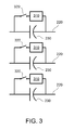
- FIG. 3 is a simplified schematic diagram of the compensation circuit according to one aspect of the present invention.
- FIG. 4 is a simplified schematic diagram of the damping circuit according to one aspect of the present invention.
- FIG. 5 is a simplified schematic diagram a power grip incorporating the compensation and damping circuit according to one aspect of the present invention.
- FIG. 6 is a simplified schematic diagram of the compensation circuit according to one aspect of the present invention.
- FIG. 7 is a simplified schematic diagram of the compensation circuit according to one aspect of the present invention.
- the modem utility grid is evolving into a network that includes disparate generation sources located far from load centers. Multiple wind farms, solar power generating stations, and other non-conventional power sources are being connected to the existing power transmission lines. Different suppliers manufacture wind turbines and each supplier can manufacture their wind turbines with different operating characteristics. Solar power suffers the same problem. This wide variability in operating characteristics makes it difficult to connect these non-conventional power-generating sources to the existing transmission lines.
- FIG. 2 illustrates a simplified example of one typical utility grid 200 .
- One or more non-conventional generating sources 210 can be connected to various parts of the grid.
- the non-conventional generating sources 210 can comprise various types of prime movers (e.g., wind turbines, wind farms, solar generating stations, etc.), and may be characterized by non-conventional electrical interfaces to the grid.
- prime movers e.g., wind turbines, wind farms, solar generating stations, etc.
- the non-conventional electrical interfaces may include induction generators or power electronic systems that can interact adversely with lightly damped series resonances in the transmission grid.
- the non-conventional generating sources 210 can comprise individual sources (e.g., a single wind turbine) or a group of sources (e.g., a wind farm comprising many turbines). Individual wind turbines may have power ratings of about 1.5 to about 3.0 MW or more, and wind farms may have a collective power rating of about 100 to about 500 MW or more. These ranges are for illustrative purposes only and may extend above or below the ranges given.
- the grid 200 may also include one or more conventional generating sources 240 and one or more loads 250 .
- Conventional generating sources typically comprise synchronous machines and may have power ratings of about 100 MW to 1300 MW or more per machine.
- An example of a conventional generating source is a gas or steam powered turbine that drives an electrical generator.
- the series capacitors 230 are required in long transmission lines 220 to compensate for the inherent inductive reactance.
- the disadvantage to series compensation is that it creates lightly damped series resonances having frequency below the synchronous frequency (i.e., subsynchronous).
- the non-conventional generators 210 can interact with the lightly damped series resonances in the transmission lines 220 in a number of ways, which can cause damage to the generators 210 .
- IGE induction generator effect
- a transmission line owner/operator may expend a large amount of labor and expense to individually tailor their transmission line to each disparate power source.
- the developers of each non-conventional power generating station must work in great detail with the vendor(s) of their generating equipment and with the vendor(s) of other non-conventional generating-station developers to coordinate their operating characteristics to accommodate the transmission grid. Such coordination is not only extremely onerous and expensive to achieve, but is prohibited by existing regulations governing competitive generation markets.
- An aspect of the present invention provides a transmission-compensation system that can couple multiple disparate generation sources to a common electrical grid, without the requirement for extensive coordination between generating stations, or requiring expensive and difficult efforts by the transmission system operator. Further aspects of the system of the present invention provide for damping subsychronous series resonance at the series capacitor location.
- FIG. 3 illustrates an improved series compensation circuit according to one aspect of the present invention.
- the transmission line 220 is series compensated by series capacitor 230 .
- a damping circuit 310 is placed in parallel with capacitor 230 .
- the damping circuit can be broadly tuned to decrease or eliminate subsynchronous resonance caused by capacitor 230 .
- a switch 320 may also be placed in series with damping circuit 310 .
- the switch 320 can isolate the damping circuit in case of failure or for system maintenance. It is to be understood that a switch 320 could be placed on both sides of damping circuit 310 if desired.
- FIG. 6 illustrates a transmission line 220 having three phases where the damping circuit 310 is connected to only one phase of transmission line 220 .
- FIG. 7 illustrates a transmission line 220 having three phases where the damping circuit 310 is connected to only two phases of transmission line 220 .
- FIG. 4 illustrates a schematic circuit diagram of one embodiment of damping circuit 310 , according to aspects of the present invention.
- the damping circuit is comprised of resistor 412 , capacitor 414 and inductor 416 .
- the damping circuit can be placed in parallel with the series compensation capacitor 230 or transmission line 220 .
- Switch 320 is optional and not shown in this embodiment.
- the resistor 412 damps the subsychnronous series resonance caused by capacitor 230 .
- a capacitor 414 and inductor 416 are connected in parallel, and in series with resistor 412 .
- the capacitor 414 and inductor 416 block current in resistor 412 at the synchronous frequency and reduce losses, which would have been attributed to resistor 412 .
- the passive components of the damping circuit are tuned for a broadband response, to compensate for all types of non-conventional power generating sources 210 , which may be connected to transmission line 220 .
- FIG. 5 illustrates a simplified schematic of a utility grid incorporating aspects of the present invention.
- the damping circuit 510 is shown connected in parallel to the series capacitors 230 .
- the damping circuit 510 may be a single or multiple (e.g., 2 or 3) phase version of damping circuit 310 .
- Switches 320 (not shown in FIG. 5 ) may also be included in damping circuit 510 .
- the damping circuit 510 protects the non-conventional power generating sources 210 from damage due to subsynchronous resonance.
- damping circuit of the present invention could be placed on one, two or all three phases.
- the passive components of the damping circuit could also be configured in a variety of ways.
- a resistor is shown connected in series to a capacitor and inductor connected in parallel.
- the resistor 412 could be replaced by a resistor connected in series with an inductor, a resistor connected in series with an inductor and capacitor, a resistor connected in parallel with a series connected inductor and capacitor, and other suitable configurations.
- the damping circuit could also be configured as a parallel connected resistor, inductor and capacitor.
- the switch 320 could also be configured to switch to a backup damping circuit if the primary damping circuit 310 fails.
- two or more damping circuits could be connected in parallel, but isolated via one or more switches. If a primary damping circuit failed, a local or remote control signal could be activated to operate one or more switches to disconnect the failed primary damping circuit, and switch in a secondary or backup damping circuit. The control of the switches could also be performed locally as well.
Abstract
Description
Claims (20)
Priority Applications (3)
| Application Number | Priority Date | Filing Date | Title |
|---|---|---|---|
| US12/249,404 US8106540B2 (en) | 2008-10-10 | 2008-10-10 | Compensation system for power transmission |
| US12/418,003 US8063515B2 (en) | 2008-10-10 | 2009-04-03 | Compensation system for power transmission |
| DE102009044197A DE102009044197A1 (en) | 2008-10-10 | 2009-10-07 | Improved compensation system for energy transfer |
Applications Claiming Priority (1)
| Application Number | Priority Date | Filing Date | Title |
|---|---|---|---|
| US12/249,404 US8106540B2 (en) | 2008-10-10 | 2008-10-10 | Compensation system for power transmission |
Related Child Applications (1)
| Application Number | Title | Priority Date | Filing Date |
|---|---|---|---|
| US12/418,003 Continuation-In-Part US8063515B2 (en) | 2008-10-10 | 2009-04-03 | Compensation system for power transmission |
Publications (2)
| Publication Number | Publication Date |
|---|---|
| US20100090537A1 US20100090537A1 (en) | 2010-04-15 |
| US8106540B2 true US8106540B2 (en) | 2012-01-31 |
Family
ID=41821512
Family Applications (1)
| Application Number | Title | Priority Date | Filing Date |
|---|---|---|---|
| US12/249,404 Active 2029-10-13 US8106540B2 (en) | 2008-10-10 | 2008-10-10 | Compensation system for power transmission |
Country Status (2)
| Country | Link |
|---|---|
| US (1) | US8106540B2 (en) |
| DE (1) | DE102009044197A1 (en) |
Cited By (4)
| Publication number | Priority date | Publication date | Assignee | Title |
|---|---|---|---|---|
| US20100039076A1 (en) * | 2008-08-12 | 2010-02-18 | Rolls-Royce Plc | Electromechanical arrangement |
| US20110109085A1 (en) * | 2009-11-10 | 2011-05-12 | Nelson Robert J | Power Oscillation Damping Employing a Full or Partial Conversion Wind Turbine |
| US8847559B1 (en) * | 2013-07-24 | 2014-09-30 | Robert Ryan Jameson Horne | Generator system and method of operation |
| US9960600B1 (en) | 2016-10-31 | 2018-05-01 | General Electric Company | Detection and mitigation of instability of synchronous machines |
Families Citing this family (5)
| Publication number | Priority date | Publication date | Assignee | Title |
|---|---|---|---|---|
| US8063515B2 (en) * | 2008-10-10 | 2011-11-22 | General Electric Company | Compensation system for power transmission |
| DE102010035020A1 (en) * | 2010-08-20 | 2012-02-23 | Steca Elektronik Gmbh | Buck converter circuit, inverter circuit arrangement and operating method |
| US8558405B2 (en) | 2011-05-26 | 2013-10-15 | Siemens Aktiengesellschaft | Method and system for operating and controlling a wind turbine to prevent excitation of subsynchronous oscillations within the wind turbine |
| US10199828B2 (en) * | 2015-08-16 | 2019-02-05 | Oren TAMIR | Phase compensation system |
| CN109193705B (en) * | 2018-11-15 | 2021-05-25 | 华北电力科学研究院有限责任公司 | Method and device for inhibiting subsynchronous resonance of doubly-fed wind turbine generator |
Citations (19)
| Publication number | Priority date | Publication date | Assignee | Title |
|---|---|---|---|---|
| US3555291A (en) | 1968-05-16 | 1971-01-12 | Gen Electric | Power system filter |
| US3859542A (en) * | 1973-09-12 | 1975-01-07 | Inductotherm Corp | Harmonic and power factor compensation means and method for power systems controlled by a non-linear device |
| US3881137A (en) | 1973-01-17 | 1975-04-29 | Ass Elect Ind | Frequency selective damping circuits |
| US4355241A (en) * | 1980-08-15 | 1982-10-19 | Electric Power Research Institute, Inc. | Means for damping subsynchronous oscillations in an AC power system including overload protection |
| US4616286A (en) * | 1982-08-02 | 1986-10-07 | Puroflow Corporation | Power line filter |
| US4623830A (en) * | 1983-07-13 | 1986-11-18 | Bbc Brown, Boveri & Company, Limited | Alternating-current machine drive |
| US4698721A (en) * | 1983-11-07 | 1987-10-06 | Puroflow Corp. | Power line filter for transient and continuous noise suppression |
| US4843513A (en) | 1987-05-06 | 1989-06-27 | Asea Brown Boveri Ab | Method and arrangement for protecting turbine generators against subsynchronous resonances occurring in power transmission systems |
| US5262677A (en) * | 1991-10-24 | 1993-11-16 | Ramirez Alberto R | Reactor subsynchronous tuning scheme |
| US5825162A (en) * | 1994-07-25 | 1998-10-20 | Hitachi, Ltd. | Electric power flow controller |
| US5864185A (en) * | 1996-03-28 | 1999-01-26 | General Electric Company | Sub-synchronous resonance filters for series capacitors |
| US6021035A (en) | 1995-05-31 | 2000-02-01 | General Electric Company | Apparatus for protection of power-electronics in series compensating systems |
| US6075425A (en) * | 1998-01-14 | 2000-06-13 | Siemens Aktiengesellschaft | Damping filter arrangement for converters having a regulated voltage source and sinusoidal phase currents |
| US6157552A (en) | 1999-12-20 | 2000-12-05 | General Electric Company | Sub-harmonic detection and control system |
| US20020005668A1 (en) * | 1998-12-04 | 2002-01-17 | Pierre Couture | Power flow management in an electric power grid |
| US20050225263A1 (en) * | 2002-07-15 | 2005-10-13 | Suzanne Van Egmond | Method and device for identifying the type of discharge lamp |
| US7244524B2 (en) * | 2002-09-13 | 2007-07-17 | Proton Energy Systems, Inc. | Method and system for balanced control of backup power |
| US7298059B2 (en) | 2004-12-17 | 2007-11-20 | General Electric Company | System and method for operating a wind farm under high wind speed conditions |
| US7939956B1 (en) * | 2010-04-09 | 2011-05-10 | General Electric Company | Torsional protection system and method for wind turbine |
-
2008
- 2008-10-10 US US12/249,404 patent/US8106540B2/en active Active
-
2009
- 2009-10-07 DE DE102009044197A patent/DE102009044197A1/en active Pending
Patent Citations (19)
| Publication number | Priority date | Publication date | Assignee | Title |
|---|---|---|---|---|
| US3555291A (en) | 1968-05-16 | 1971-01-12 | Gen Electric | Power system filter |
| US3881137A (en) | 1973-01-17 | 1975-04-29 | Ass Elect Ind | Frequency selective damping circuits |
| US3859542A (en) * | 1973-09-12 | 1975-01-07 | Inductotherm Corp | Harmonic and power factor compensation means and method for power systems controlled by a non-linear device |
| US4355241A (en) * | 1980-08-15 | 1982-10-19 | Electric Power Research Institute, Inc. | Means for damping subsynchronous oscillations in an AC power system including overload protection |
| US4616286A (en) * | 1982-08-02 | 1986-10-07 | Puroflow Corporation | Power line filter |
| US4623830A (en) * | 1983-07-13 | 1986-11-18 | Bbc Brown, Boveri & Company, Limited | Alternating-current machine drive |
| US4698721A (en) * | 1983-11-07 | 1987-10-06 | Puroflow Corp. | Power line filter for transient and continuous noise suppression |
| US4843513A (en) | 1987-05-06 | 1989-06-27 | Asea Brown Boveri Ab | Method and arrangement for protecting turbine generators against subsynchronous resonances occurring in power transmission systems |
| US5262677A (en) * | 1991-10-24 | 1993-11-16 | Ramirez Alberto R | Reactor subsynchronous tuning scheme |
| US5825162A (en) * | 1994-07-25 | 1998-10-20 | Hitachi, Ltd. | Electric power flow controller |
| US6021035A (en) | 1995-05-31 | 2000-02-01 | General Electric Company | Apparatus for protection of power-electronics in series compensating systems |
| US5864185A (en) * | 1996-03-28 | 1999-01-26 | General Electric Company | Sub-synchronous resonance filters for series capacitors |
| US6075425A (en) * | 1998-01-14 | 2000-06-13 | Siemens Aktiengesellschaft | Damping filter arrangement for converters having a regulated voltage source and sinusoidal phase currents |
| US20020005668A1 (en) * | 1998-12-04 | 2002-01-17 | Pierre Couture | Power flow management in an electric power grid |
| US6157552A (en) | 1999-12-20 | 2000-12-05 | General Electric Company | Sub-harmonic detection and control system |
| US20050225263A1 (en) * | 2002-07-15 | 2005-10-13 | Suzanne Van Egmond | Method and device for identifying the type of discharge lamp |
| US7244524B2 (en) * | 2002-09-13 | 2007-07-17 | Proton Energy Systems, Inc. | Method and system for balanced control of backup power |
| US7298059B2 (en) | 2004-12-17 | 2007-11-20 | General Electric Company | System and method for operating a wind farm under high wind speed conditions |
| US7939956B1 (en) * | 2010-04-09 | 2011-05-10 | General Electric Company | Torsional protection system and method for wind turbine |
Cited By (6)
| Publication number | Priority date | Publication date | Assignee | Title |
|---|---|---|---|---|
| US20100039076A1 (en) * | 2008-08-12 | 2010-02-18 | Rolls-Royce Plc | Electromechanical arrangement |
| US8427117B2 (en) * | 2008-08-12 | 2013-04-23 | Rolls-Royce Plc | Electromechanical arrangement |
| US20110109085A1 (en) * | 2009-11-10 | 2011-05-12 | Nelson Robert J | Power Oscillation Damping Employing a Full or Partial Conversion Wind Turbine |
| US9478987B2 (en) * | 2009-11-10 | 2016-10-25 | Siemens Aktiengesellschaft | Power oscillation damping employing a full or partial conversion wind turbine |
| US8847559B1 (en) * | 2013-07-24 | 2014-09-30 | Robert Ryan Jameson Horne | Generator system and method of operation |
| US9960600B1 (en) | 2016-10-31 | 2018-05-01 | General Electric Company | Detection and mitigation of instability of synchronous machines |
Also Published As
| Publication number | Publication date |
|---|---|
| DE102009044197A1 (en) | 2010-04-15 |
| US20100090537A1 (en) | 2010-04-15 |
Similar Documents
| Publication | Publication Date | Title |
|---|---|---|
| US8063515B2 (en) | Compensation system for power transmission | |
| US8106540B2 (en) | Compensation system for power transmission | |
| Nøland et al. | Excitation system technologies for wound-field synchronous machines: Survey of solutions and evolving trends | |
| US7939956B1 (en) | Torsional protection system and method for wind turbine | |
| CN101919132B (en) | Apparatus and method for operating a wind turbine under low utility grid voltage conditions | |
| Hansen et al. | Conceptual survey of generators and power electronics for wind turbines | |
| EP1780861B1 (en) | Detection of islanding in power grids | |
| US7253537B2 (en) | System and method of operating double fed induction generators | |
| EP2866323B1 (en) | Auxiliary electric power system and method of regulating voltages of the same | |
| Mansouri et al. | Internal electrical protection of wind turbine with doubly fed induction generator | |
| Huang et al. | Fault ride-through configuration and transient management scheme for self-excited induction generator-based wind turbine | |
| Faria et al. | Robust Nonlinear Double Integral Sliding Mode Controller Design for Mitigating SSR in DFIG-Based Wind Farms | |
| US10566786B2 (en) | Fault current enhancement for energy resources with power electronic interface | |
| Samoylenko et al. | Semiconductor power electronics for synchronous distributed generation | |
| Rashid et al. | Asymmetrical fault ride through capacity augmentation of DFIG based wind farms by parallel resonance fault current limiter | |
| Daniel et al. | Subsynchronous phenomena and wind turbine generators | |
| Igbinovia et al. | Josef T systems | |
| US6661207B2 (en) | Apparatus and method for protecting synchronous generators against off-nominal frequency deviation and alternating forces excitation | |
| Hoseinzadeh et al. | RTDS demonstration of harmonic amplification in under sea/ground cables of offshore wind farms | |
| Ahmed et al. | Stability enhancement in smart grid by using superconducting fault current limiter | |
| Guerrero | Grid code interrelation, wind generation evolution and reactive compensation, special topics inside a grid code | |
| CN102723739A (en) | Wind power generation system | |
| Ghadiri et al. | Impact of islanding on governor signal of distributed resources | |
| Rajasekaran et al. | Research Issues in DFIG Based Wind Energy System | |
| Zevallos et al. | Inverter Control Strategy to Reduce the Synchronous Machine Rotor Angle Excursions |
Legal Events
| Date | Code | Title | Description |
|---|---|---|---|
| AS | Assignment |
Owner name: GENERAL ELECTRIC COMPANY,NEW YORK Free format text: ASSIGNMENT OF ASSIGNORS INTEREST;ASSIGNORS:LARSEN, EINAR V.;ENGLISH, BRUCE E.;DROBNJAK, GORAN;SIGNING DATES FROM 20081008 TO 20081010;REEL/FRAME:021667/0800 Owner name: GENERAL ELECTRIC COMPANY, NEW YORK Free format text: ASSIGNMENT OF ASSIGNORS INTEREST;ASSIGNORS:LARSEN, EINAR V.;ENGLISH, BRUCE E.;DROBNJAK, GORAN;SIGNING DATES FROM 20081008 TO 20081010;REEL/FRAME:021667/0800 |
|
| STCF | Information on status: patent grant |
Free format text: PATENTED CASE |
|
| FPAY | Fee payment |
Year of fee payment: 4 |
|
| MAFP | Maintenance fee payment |
Free format text: PAYMENT OF MAINTENANCE FEE, 8TH YEAR, LARGE ENTITY (ORIGINAL EVENT CODE: M1552); ENTITY STATUS OF PATENT OWNER: LARGE ENTITY Year of fee payment: 8 |
|
| MAFP | Maintenance fee payment |
Free format text: PAYMENT OF MAINTENANCE FEE, 12TH YEAR, LARGE ENTITY (ORIGINAL EVENT CODE: M1553); ENTITY STATUS OF PATENT OWNER: LARGE ENTITY Year of fee payment: 12 |
|
| AS | Assignment |
Owner name: GE INFRASTRUCTURE TECHNOLOGY LLC, SOUTH CAROLINA Free format text: ASSIGNMENT OF ASSIGNORS INTEREST;ASSIGNOR:GENERAL ELECTRIC COMPANY;REEL/FRAME:065727/0001 Effective date: 20231110 |