US8154780B2 - Holographic image projection systems - Google Patents
Holographic image projection systems Download PDFInfo
- Publication number
- US8154780B2 US8154780B2 US12/335,423 US33542308A US8154780B2 US 8154780 B2 US8154780 B2 US 8154780B2 US 33542308 A US33542308 A US 33542308A US 8154780 B2 US8154780 B2 US 8154780B2
- Authority
- US
- United States
- Prior art keywords
- image
- holographic
- target image
- image data
- projection
- Prior art date
- Legal status (The legal status is an assumption and is not a legal conclusion. Google has not performed a legal analysis and makes no representation as to the accuracy of the status listed.)
- Expired - Fee Related, expires
Links
- 230000001154 acute effect Effects 0.000 claims abstract description 35
- 238000005286 illumination Methods 0.000 claims abstract description 10
- 238000000034 method Methods 0.000 claims description 59
- 238000013507 mapping Methods 0.000 claims description 30
- 230000015654 memory Effects 0.000 claims description 12
- 230000008859 change Effects 0.000 claims description 9
- 230000001419 dependent effect Effects 0.000 claims description 8
- 230000004075 alteration Effects 0.000 claims description 7
- 238000006243 chemical reaction Methods 0.000 claims description 6
- 230000008569 process Effects 0.000 claims description 4
- 238000001514 detection method Methods 0.000 claims description 2
- 230000004044 response Effects 0.000 claims description 2
- 238000013459 approach Methods 0.000 description 17
- 230000003287 optical effect Effects 0.000 description 12
- 239000000872 buffer Substances 0.000 description 9
- 238000012545 processing Methods 0.000 description 8
- 230000000694 effects Effects 0.000 description 7
- 230000006870 function Effects 0.000 description 6
- 238000004364 calculation method Methods 0.000 description 5
- 238000009826 distribution Methods 0.000 description 5
- 230000002123 temporal effect Effects 0.000 description 5
- 230000003044 adaptive effect Effects 0.000 description 4
- 238000004422 calculation algorithm Methods 0.000 description 4
- 238000012937 correction Methods 0.000 description 4
- 238000010586 diagram Methods 0.000 description 4
- 239000003086 colorant Substances 0.000 description 3
- 230000002441 reversible effect Effects 0.000 description 3
- 238000013519 translation Methods 0.000 description 3
- 230000008901 benefit Effects 0.000 description 2
- 239000005262 ferroelectric liquid crystals (FLCs) Substances 0.000 description 2
- 230000001788 irregular Effects 0.000 description 2
- 239000004973 liquid crystal related substance Substances 0.000 description 2
- 238000004519 manufacturing process Methods 0.000 description 2
- 241001263092 Alchornea latifolia Species 0.000 description 1
- 238000012935 Averaging Methods 0.000 description 1
- 230000005355 Hall effect Effects 0.000 description 1
- 239000000654 additive Substances 0.000 description 1
- 230000000996 additive effect Effects 0.000 description 1
- 238000003491 array Methods 0.000 description 1
- 230000015572 biosynthetic process Effects 0.000 description 1
- 238000004891 communication Methods 0.000 description 1
- 238000013461 design Methods 0.000 description 1
- 238000005516 engineering process Methods 0.000 description 1
- 238000011156 evaluation Methods 0.000 description 1
- 230000006872 improvement Effects 0.000 description 1
- 238000007620 mathematical function Methods 0.000 description 1
- 239000011159 matrix material Substances 0.000 description 1
- 230000007246 mechanism Effects 0.000 description 1
- 239000000203 mixture Substances 0.000 description 1
- 238000012986 modification Methods 0.000 description 1
- 230000004048 modification Effects 0.000 description 1
- 229920001690 polydopamine Polymers 0.000 description 1
- 238000007781 pre-processing Methods 0.000 description 1
- 238000013139 quantization Methods 0.000 description 1
- 230000009467 reduction Effects 0.000 description 1
- 238000002922 simulated annealing Methods 0.000 description 1
- 238000001228 spectrum Methods 0.000 description 1
- 238000003860 storage Methods 0.000 description 1
- 230000001629 suppression Effects 0.000 description 1
- 238000003786 synthesis reaction Methods 0.000 description 1
- 230000009466 transformation Effects 0.000 description 1
- 230000001131 transforming effect Effects 0.000 description 1
- 230000000007 visual effect Effects 0.000 description 1
- 230000003936 working memory Effects 0.000 description 1
Images


Classifications
-
- G06T5/80—
-
- G—PHYSICS
- G03—PHOTOGRAPHY; CINEMATOGRAPHY; ANALOGOUS TECHNIQUES USING WAVES OTHER THAN OPTICAL WAVES; ELECTROGRAPHY; HOLOGRAPHY
- G03H—HOLOGRAPHIC PROCESSES OR APPARATUS
- G03H1/00—Holographic processes or apparatus using light, infrared or ultraviolet waves for obtaining holograms or for obtaining an image from them; Details peculiar thereto
- G03H1/22—Processes or apparatus for obtaining an optical image from holograms
-
- H—ELECTRICITY
- H04—ELECTRIC COMMUNICATION TECHNIQUE
- H04N—PICTORIAL COMMUNICATION, e.g. TELEVISION
- H04N5/00—Details of television systems
- H04N5/74—Projection arrangements for image reproduction, e.g. using eidophor
- H04N5/7416—Projection arrangements for image reproduction, e.g. using eidophor involving the use of a spatial light modulator, e.g. a light valve, controlled by a video signal
-
- G—PHYSICS
- G03—PHOTOGRAPHY; CINEMATOGRAPHY; ANALOGOUS TECHNIQUES USING WAVES OTHER THAN OPTICAL WAVES; ELECTROGRAPHY; HOLOGRAPHY
- G03H—HOLOGRAPHIC PROCESSES OR APPARATUS
- G03H1/00—Holographic processes or apparatus using light, infrared or ultraviolet waves for obtaining holograms or for obtaining an image from them; Details peculiar thereto
- G03H1/22—Processes or apparatus for obtaining an optical image from holograms
- G03H1/2202—Reconstruction geometries or arrangements
- G03H1/2205—Reconstruction geometries or arrangements using downstream optical component
-
- G—PHYSICS
- G03—PHOTOGRAPHY; CINEMATOGRAPHY; ANALOGOUS TECHNIQUES USING WAVES OTHER THAN OPTICAL WAVES; ELECTROGRAPHY; HOLOGRAPHY
- G03H—HOLOGRAPHIC PROCESSES OR APPARATUS
- G03H1/00—Holographic processes or apparatus using light, infrared or ultraviolet waves for obtaining holograms or for obtaining an image from them; Details peculiar thereto
- G03H1/22—Processes or apparatus for obtaining an optical image from holograms
- G03H1/2249—Holobject properties
-
- G—PHYSICS
- G03—PHOTOGRAPHY; CINEMATOGRAPHY; ANALOGOUS TECHNIQUES USING WAVES OTHER THAN OPTICAL WAVES; ELECTROGRAPHY; HOLOGRAPHY
- G03H—HOLOGRAPHIC PROCESSES OR APPARATUS
- G03H1/00—Holographic processes or apparatus using light, infrared or ultraviolet waves for obtaining holograms or for obtaining an image from them; Details peculiar thereto
- G03H1/22—Processes or apparatus for obtaining an optical image from holograms
- G03H1/2202—Reconstruction geometries or arrangements
- G03H1/2205—Reconstruction geometries or arrangements using downstream optical component
- G03H2001/2213—Diffusing screen revealing the real holobject, e.g. container filed with gel to reveal the 3D holobject
- G03H2001/2215—Plane screen
- G03H2001/2218—Plane screen being perpendicular to optical axis
-
- G—PHYSICS
- G03—PHOTOGRAPHY; CINEMATOGRAPHY; ANALOGOUS TECHNIQUES USING WAVES OTHER THAN OPTICAL WAVES; ELECTROGRAPHY; HOLOGRAPHY
- G03H—HOLOGRAPHIC PROCESSES OR APPARATUS
- G03H2210/00—Object characteristics
- G03H2210/20—2D object
Definitions
- This invention relates to holographic image projection systems, more particularly to systems which are able to project down on to a table at an acute angle, preferably as well as projecting forwards.
- the invention also provides related methods and corresponding processor control code.
- Table down projection Projecting downwards and outwards onto a flat surface such as a tabletop entails projecting at an acute angle onto the display surface (taking this as the angle between the centre of the output of the projection optics and the middle of the displayed image—this angle, to a line in the surface, is less that 90°).
- Table down projection is not readily achievable by conventional image display techniques; scanning image display systems have a narrow throw angle and thus find it difficult to achieve a useful image size whilst projection systems, especially those based on LEDs (light emitting diodes) which have a wide light output angle, find it difficult to achieve a useful depth of field.
- a holographic image projection system for projecting an image at an acute angle onto a surface
- the system comprising: a spatial light modulator (SLM) to display a hologram; an illumination system to illuminate said displayed hologram; projection optics to project light from said illuminated displayed hologram onto said surface at an acute angle form said image; and a processor having an input to receive input image data for display and an output to provide hologram data for said spatial light modulator, and wherein said processor is configured to: input image data; convert said input image data to target image data; generate from said target image data hologram data for display as a hologram on said spatial light modulator to reproduce a target image corresponding to said target image data; and output said hologram data for said spatial light modulator; and wherein said target image is distorted to compensate for said projection of said hologram at an acute angle to form said image.
- SLM spatial light modulator
- the displayed image is substantially focus-free; that is the focus of the displayed image does not substantially depend upon the distance from the holographic image projection system to the display surface.
- a demagnifying optical system may be employed to increase the divergence of the modulated light to form the displayed image, thus allowing an image of a useful size to be displayed at a practical distance.
- the field of the displayed image suffers from keystone distortion, the trapezoidal distortion of a nominally rectangular input image field caused by projection onto a surface at an angle which is not perpendicular to the axis of the output optics.
- the holographic image projection system internally generates a target image to which the inverse distortion has been applied so that when this target image is projected holographically the keystone distortion is compensated.
- the target image is the image to which a holographic transform is applied to generate hologram data for display on the SLM.
- the system also includes non-volatile memory storing mapping data for mapping between the input image and the target image.
- amplitude or intensity scale factor is applied the value of which depends upon the location (in two dimensions) of a pixel in the target image space.
- pixels of the target image which remain unpopulated may be given values by interpolation between pixels of the target image populated with pixel values.
- these extended regions or spots may overlap in the target image, in which case the value of a target image pixel may be determined by combining more particularly summing, the overlapping values (so that multiple input image pixels may contribute to the value of a single target image pixel).
- Preferred embodiments of the holographic image projection system provide a multi-colour, more particularly a full colour display.
- red, green and blue laser illumination of the SLM may be employed, time multiplexed to display three colour planes of the input image in turn.
- the blue light diverges less than the red light and thus in preferred embodiments the target image also has three colour planes in which a different scaling is employed for each colour, to compensate for the differing sizes of the projected colour image planes. More particularly, since the red light diverges most, the target image field of the red colour plane is the smallest target image field of the three target image planes (since the target image has “anti-distortion” applied).
- the size of the target image field for a colour is inversely proportional to the wavelength of light used for that colour.
- the distortion (more correctly anti-distortion) of each colour image plane may be mapped to a corresponding colour plane of the target image field using a calibration process which corrects for chromatic aberration within the projection system such as chromatic aberration within the projection optics, chromatic aberration caused by slight misalignment between rays for different colours within the optics, and the light.
- the holographic techniques employed in preferred embodiments of the projector facilitate miniaturisation of the projector. These techniques also facilitate handling of extreme distortion caused by projection onto a surface on which the projector is placed, this extreme distortion resulting from the geometry illustrated in later FIG. 1 c in combination with the small size of the projector.
- the surface onto which the image is projected is no more than 1 m, 0.5 m, 0.3 m, 0.2 m, 0.15 m, or 0.1 m away from the output of the projection optics 102 .
- the distance from the output of the projection optics to the furthest edge of the displayed image (d 2 in FIG.
- the invention provides a holographic image projection device having two configurations, a first configuration in which said device is able to project towards a vertical screen or surface and a second, table down projection configuration in which said device is configured to stand on a table surface and project downwards into said table surface, and wherein the device is further configured to apply distortion compensation to a holographically projected image when in said table down projection configuration, said distortion compensation compensating for distortion arising from projection of said image onto said table surface at an acute angle.
- the device incorporates a stand such as a bipod or tripod stand, and preferably also includes a sensor to automatically detect when the device is in its table-down projection configuration, automatically applying distortion compensation in response to such detection.
- the projection optics may be adjusted to alter between forward and table-down projection, again preferably automatically sensing the configuration. In a simple configuration this could be achieved with a moveable or switchable mirror, but an alternative approach employs a wide angle or fisheye lens which when translated perpendicular to the output axis of the optics may be employed to move from forward projection to table-down projection at an acute angle.
- Certain embodiments also provide a method of projecting an image onto a surface at an acute angle, the method comprising: inputting display image data defining an image for display; processing said display image data to generate target image data; defining a target image for projection, wherein said target image comprises a version of said image for display distorted to compensate for projection onto said surface at said acute angle; performing a holographic transform on said target image defined by said target image data to generate hologram data for a hologram of said target image; displaying said hologram data on a spatial light modulator illuminated by at least one laser; and projecting light from said at least one laser modulated by said hologram data displayed on said spatial light modulator onto said surface at said acute angle, to reproduce a substantially undistorted version of said image on said surface.
- a mapping between the input image and the anti-distorted target image may comprise either an analytical mapping, based on a mathematical function, or a numerical mapping, for example, derived from a calibration procedure or both.
- target image pixels are mapped to input image pixels to lookup target image pixel values.
- the target image is also corrected for area mapping distortion and, in a colour system, preferably the different colour planes are appropriately scaled so that they reproduced in the projection surface at substantially the same size.
- a carrier carrying processor control code to implement a method of projecting an image onto a surface at an acute angle, the method comprising: inputting display image data defining an image for display; processing said display image data to generate target image data defining a target image for projection, wherein said target image comprises a version of said image for display distorted to compensate for projection onto said surface at said acute angle; performing a holographic transform on said target image defined by said target image data to generate hologram data for a hologram of said target image; and outputting said hologram data for display of said hologram on a spatial light modulator (SLM) for reproducing said image for display on said surface.
- SLM spatial light modulator
- Certain embodiments also provide a method of sharing an image between a group of people, the method comprising: providing a holographic image projection device having a table-down projection configuration in which said device is configured to stand on a table surface and project downwards onto said table surface; and projecting an image holographically onto said table surface to share said image.
- devices and methods preferably an (AD)OSPR-type procedure is employed to generate the hologram data.
- AD an (AD)OSPR-type procedure
- a single displayed image or image frame is generated using a plurality of temporal holographic subframes displayed in rapid succession such that the corresponding images average in an observer's eye to give the impression of a single, noise-reduced displayed image.
- FIGS. 5 a to 5 c show, respectively, examples of different types of keystone distortion, an example calibration pattern for correction of keystone distortion, and an example target image field for processing by a hologram generation procedure for holographic image projection according to an embodiment of the invention
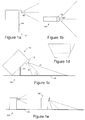
- FIG. 1 a shows a side view of an embodiment of a holographic image projection device 100 having 2 configurations, the first configuration in which the device projects forwards, and a second configuration (shown in FIG. 1 c ) in which the device projects outwards and downwards onto a surface 106 such as a table-top.
- the device includes an output lens 102 and a foldable stand, for example a bipod stand 104 to support the device in its table-down configuration.
- the foldable support 104 or some similar mechanism supports the device at a known angle to the surface 106 in its table-down configuration, which has the advantage that the degree of keystone distortion is also known and can therefore automatically be compensated for.
- the table-down configuration is a pre-determined configuration a calibration procedure can be used to determine not only the general keystone distortion but also other aberrations which will typically be present albeit at a second order, so that compensation may also be made for these.
- Preferred embodiments of the invention use an OSPR-type hologram generation procedure, and we therefore describe examples of such procedures below.
- embodiments of the invention are not restricted to such a hologram generation procedure and may be employed with other types of hologram generation procedure including, but not limited to: a Gerchberg-Saxton procedure (R. W. Gerchberg and W. O. Saxton, “A practical algorithm for the determination of phase from image and diffraction plane pictures” Optik 35, 237-246 (1972)) or a variant thereof, Direct Binary Search (M. A. Seldowitz, J. P. Allebach and D. W. Sweeney, “Synthesis of digital holograms by direct binary search” Appl. Opt.
- the SLM may be a liquid crystal device.
- other SLM technologies to effect phase modulation may be employed, such as a pixellated MEMS-based piston actuator device.
- FIG. 3 a shows a block diagram of a hologram data calculation system configured to implement this procedure.
- the input to the system is preferably image data from a source such as a computer, although other sources are equally applicable.
- the input data is temporarily stored in one or more input buffer, with control signals for this process being supplied from one or more controller units within the system.
- the input (and output) buffers preferably comprise dual-port memory such that data may be written into the buffer and read out from the buffer simultaneously.
- the control signals comprise timing, initialisation and flow-control information and preferably ensure that one or more holographic sub-frames are produced and sent to the SLM per video frame period.
- the output from the input comprises an image frame, labelled I, and this becomes the input to a hardware block (although in other embodiments some or all of the processing may be performed in software).
- the hardware block performs a series of operations on each of the aforementioned image frames, I, and for each one produces one or more holographic sub-frames, h, which are sent to one or more output buffer.
- the sub-frames are supplied from the output buffer to a display device, such as a SLM, optionally via a driver chip.
- FIG. 3 b shows details of the hardware block of FIG. 3 a ; this comprises a set of elements designed to generate one or more holographic sub-frames for each image frame that is supplied to the block.
- one image frame, I xy is supplied one or more times per video frame period as an input.
- Each image frame, I xy is then used to produce one or more holographic sub-frames by means of a set of operations comprising one or more of: a phase modulation stage, a space-frequency transformation stage and a quantisation stage.
- a set of N sub-frames is generated per frame period by means of using either one sequential set of the aforementioned operations, or a several sets of such operations acting in parallel on different sub-frames, or a mixture of these two approaches.
- phase-modulation block The purpose of the phase-modulation block is to redistribute the energy of the input frame in the spatial-frequency domain, such that improvements in final image quality are obtained after performing later operations.
- FIG. 3 c shows an example of how the energy of a sample image is distributed before and after a phase-modulation stage in which a pseudo-random phase distribution is used. It can be seen that modulating an image by such a phase distribution has the effect of redistributing the energy more evenly throughout the spatial-frequency domain.
- pseudo-random binary-phase modulation data may be generated (for example, a shift register with feedback).
- the quantisation block takes complex hologram data, which is produced as the output of the preceding space-frequency transform block, and maps it to a restricted set of values, which correspond to actual modulation levels that can be achieved on a target SLM (the different quantised phase retardation levels may need not have a regular distribution).
- the number of quantisation levels may be set at two, for example for an SLM producing phase retardations of 0 or ⁇ at each pixel.
- the quantiser is configured to separately quantise real and imaginary components of the holographic sub-frame data to generate a pair of holographic sub-frames, each with two (or more) phase-retardation levels, for the output buffer.
- FIG. 3 d shows an example of such a system. It can be shown that for discretely pixellated fields, the real and imaginary components of the complex holographic sub-frame data are uncorrelated, which is why it is valid to treat the real and imaginary components independently and produce two uncorrelated holographic sub-frames.
- binary phase SLM is the SXGA (1280 ⁇ 1024) reflective binary phase modulating ferroelectric liquid crystal SLM made by CRL Opto (Forth Dimension Displays Limited, of Scotland, UK).
- a ferroelectric liquid crystal SLM is advantageous because of its fast switching time.
- Binary phase devices are convenient but some preferred embodiments of the method use so-called multiphase spatial light modulators as distinct from binary phase spatial light modulators (that is SLMs which have more than two different selectable phase delay values for a pixel as opposed to binary devices in which a pixel has only one of two phase delay values).
- Multiphase SLMs devices with three or more quantized phases
- Multiphase SLMs include continuous phase SLMs, although when driven by digital circuitry these devices are necessarily quantised to a number of discrete phase delay values.
- Binary quantization results in a conjugate image whereas the use of more than binary phase suppresses the conjugate image (see WO 2005/059660).
- One example of this approach comprises an adaptive OSPR algorithm which uses feedback as follows: each stage n of the algorithm calculates the noise resulting from the previously-generated holograms H 1 to H n-1 , and factors this noise into the generation of the hologram H n to cancel it out. As a result, it can be shown that noise variance falls as 1/N 2 .
- An example procedure takes as input a target image T, and a parameter N specifying the desired number of hologram subframes to produce, and outputs a set of N holograms H 1 to H N which, when displayed sequentially at an appropriate rate, form as a far-field image a visual representation of T which is perceived as high quality:
- a random phase factor ⁇ is added at each stage to each pixel of the target image, and the target image is adjusted to take the noise from the previous stages into account, calculating a scaling factor ⁇ to match the intensity of the noisy “running total” energy F with the target image energy (T′) 2 .
- the total noise energy from the previous n ⁇ 1 stages is given by ⁇ F ⁇ (n ⁇ 1)(T′) 2 , according to the relation
- T′ target amplitude
- equal to the square root of this energy value, i.e.
- H represents an intermediate fully-complex hologram formed from the target T′′ and is calculated using an inverse Fourier transform operation. It is quantized to binary phase to form the output hologram H n , i.e.
- FIG. 4 a outlines this method and FIG. 4 b shows details of an example implementation, as described above.
- an ADOSPR-type method of generating data for displaying an image comprises generating from the displayed image data holographic data for each subframe such that replay of these gives the appearance of the image, and, when generating holographic data for a subframe, compensating for noise in the displayed image arising from one or more previous subframes of the sequence of holographically generated subframes.
- the compensating comprises determining a noise compensation frame for a subframe; and determining an adjusted version of the displayed image data using the noise compensation frame, prior to generation of holographic data for a subframe.
- the adjusting comprises transforming the previous subframe data from a frequency domain to a spatial domain, and subtracting the transformed data from data derived from the displayed image data.
- the total field size of an image scales with the wavelength of light employed to illuminate the SLM, red light being diffracted more by the pixels of the SLM than blue light and thus giving rise to a larger total field size.
- a colour holographic projection system could be constructed by superimposed simply three optical channels, red, blue and green but this is difficult because the different colour images must be aligned.
- a better approach is to create a combined beam comprising red, green and blue light, as shown in FIG. 2 above, and to provide this to a common SLM, scaling the sizes of the images to match one another.
- An example system comprises red, green, and blue collimated laser diode light sources, for example at wavelengths of 638 nm, 532 nm and 445 nm, driven in a time-multiplexed manner.
- Each light source comprises a laser diode and, if necessary, a collimating lens and/or beam expander.
- the total field size of the displayed image depends upon the pixel size of the SLM but not on the number of pixels in the hologram displayed on the SLM.
- a target image for display can be padded with zeros in order to generate three colour planes of different spatial extents for blue, green and red image planes. In the holograms for each colour plane the information in the hologram is distributed over the complete set of pixels.
- FIG. 5 a this shows examples of two different types of keystone distortion of a rectangular input image 500 , the trapezoidal pattern 502 resulting from the tilting shown in FIG. 1 c , the arcuate trapezoidal pattern 504 resulting from translation of a fisheye output lens as shown in FIG. 1 e .
- the degree of distortion depends upon the height of the output lens above the projection surface, and also on the angle of tilt.
- the distortion patterns shown in FIG. 5 a maybe described analytically, as is well known to those skilled in the art. For details reference may be made to, for example, Wikipedia®.
- Example equations describing the trapezoidal distortion of FIG. 5 a are given in the prior art, for example in U.S. Pat. No. 6,367,933 (WO00/21282) at column 20 line 41 to column 21 line 6 and FIGS. 9A and 9B, to which reference may again be made for details.
- An alternative expression of the distortion, using warp polynomials, may be found in WO02/101443 at page 8 line 29 et seq., again to which reference may be made for details.
- a calibration pattern may be projected, as illustrated in FIG. 5 b , which shows on the left hand side a grid of points and on the right hand side the projected, keystone-distorted image.
- a point in the distorted image may be associated with a point in the input image to define a mapping from one to the other.
- the distortion map may be defined for a single angle if, say, the angle at which the table-down projection is used is known or defined for example by the configuration of the projector; alternatively a range of distortion maps may be defined and stored for a range of different projection angles.
- the distortion map may be determined as a calibration for a single, reference device and then applied to other devices or alternatively the distortion may be mapped individually for a given holographic projector, for example during manufacture, and this map stored in non-volatile memory within the device. In either case the distortion map may take account of distortions other than keystone distortion, for example arising from the use of optical components with imperfections in the optical arrangement of FIG. 2 . It will also be appreciated that separate distortion maps may be stored for red, green, and/or blue colour components of the projected image.
- this shows an input image 500 for display and a corresponding target image space 506 including a target image 506 a for hologram generation, distorted so that when a hologram is generated from this the projected image compensates for the keystone distortion shown in FIG. 5 a.
- the mapping between the target image 506 a and the input image 500 is described by a pair of polynomial expansions and, more particularly by two sets of polynomial coefficients for these expansions. If we refer to the target image space using coordinates (x′, y′), and the input image using coordinates (x, y) then we can define a location (x, y) in the input image space as a pair of functions ⁇ ′, g′ of the coordinates in the (anti-distorted) target image space, as follows: f ′( x′,y ′) ⁇ x g ′( x′,y ′) ⁇ y Likewise: f ( x,y ) ⁇ x′ g ( x,y ) ⁇ y′ For reasons explained further below, it is preferable that the mapping from the target to the input image rather than vice-versa is employed.
- coefficient a 00 defines position
- a 10 and a 01 define scale
- a 11 defines skew
- a 20 and so forth are higher order coefficients.
- the value of a ij is dependent on the angle of projection ⁇ , on i and on j; the value of bij is similarly dependent on ⁇ , i and j. It can be helpful to consider (x, y) space as being “camera”—that is defining what it is desired to project.
- FIG. 6 a this again shows the input image 500 and the target image 506 a for hologram generation, the latter being “anti-distorted”. More particularly FIG. 6 a shows a single pixel 507 of target image 506 a , illustrating how this pixel maps to a plurality of pixels 501 a, b, c in the input image 500 .
- This can be appreciated because the distortion effectively shortens the nearer edge of the input image as compared with the more distant edge from the output optics.
- the target image is constructed by stepping through the (x′, y′) positions in the target image 506 a and for each looking up the addresses of the corresponding pixels in the input image and using the values from these pixels, in the example pixels 501 , a, b, c , to assign a value to the corresponding pixel 507 in the target image
- the values of the input image pixels may, for example, be summed or some other approach may be employed for example selecting a value such as a mean, medium or mode value.
- preferred embodiments apply and inverse mapping, from the target to the input image space.
- mapping from the input image to the target image can leave holes in the target image, that is pixels with unpopulated values.
- a single pixel of the input image may be mapped to a regular or irregular spot with an extended size (over multiple pixels) in the target image, optionally with a super imposed intensity distribution such as a gaussian distribution.
- N represents the number of pixels in the hologram in the X and Y-directions (here for simplicity, the same number).
- the region of the target image space 506 outside image 506 a is filled with zeros and therefore in some preferred implementations the evaluation of H(X,Y) is performed over a window of target image space 506 defined by the target image 506 a , for efficiency.
- FIG. 6 b we have described above an example of a colour holographic image projection system.
- preferred embodiments of the system employ three differently scaled and/or distorted target images 506 a , as illustrated in FIG. 6 b , one of each of the three laser colours red, green and blue-denoted R, G and B in the figure.
- ⁇ ′, g′ are provided for each colour, although in other embodiments a single target image/distortion map is employed and scaled according to the wavelength of the laser light used for the respective colour plane, more particularly scaled by 1/ ⁇ .
- each pixel of a hologram calculated from the target image 506 a contributes to substantially the whole displayed image, the displayed image is scaled in inverse proportion to wavelength—that is the blue image would be smaller because the blue light is diffracted less, and therefore the blue target image enlarged so that the projected images for the three colour planes substantially match inside.
- the (1,0) and (0,1) coefficients are scaled by reciprocal wavelength, and optionally the coefficients of higher power are scaled accordingly, for example the (1,1), (2,0), and (0,2) coefficients being scaled by 1/ ⁇ 2 and so forth.
- the coefficients of higher power are scaled accordingly, for example the (1,1), (2,0), and (0,2) coefficients being scaled by 1/ ⁇ 2 and so forth.
- a 10 R 640 440 ⁇ a 10 B .
- an OSPR-type or ADOSPR approach is employed to calculate the holograms for display on the spatial light modulator, as this provides substantial efficiency advantages.
- FIG. 7 shows a flow diagram of an embodiment of a procedure to implement table-down holographic image projection according to embodiments of the invention (the procedure covers the inverse mapping and forward mapping alternatives described above).
- Data for an input image for display is received at step 700 .
- the procedure steps through the target “anti-distorted” image pixel by pixel ( 702 ) and for each target image pixel uses the inverse map to lookup one or more corresponding input image pixel values ( 704 ), where the inverse map is to multiple input image pixels averaging (or otherwise combining) these.
- the procedure then applies brightness per unit area compensation ( 706 ) as described above and is repeated for each colour plane ( 708 ).
- the procedure the inverse map is stored in the form of polynomial coefficients as described above, in non-volatile memory ( 710 ). Alternatively some other numeric representation of a map may be employed, or an analytical formula may be used.
- the “anti-distorted” target image data is then provided to a hologram generation procedure ( 716 ), in preferred embodiments and ADOSPR-type procedure as described above.
- This generates holographic data comprising multiple temporal holographic subframes for each colour plane of the target image and outputs this for display on the SLM ( 718 ).
- the SLM displays the multiple holographic subframes for each colour frame, time multiplexed in synchrony with the red, green and blue laser illumination, to provide the table-down holographically projected image ( 720 ).
- FIG. 8 a shows a first example implementation of a holographic table-down image projection system controller 202 (as shown in FIG. 2 ), including a digital signal processor 210 operating under control of processor control code (which may be provided on a storage medium such as Flash memory) to implement a procedure as described above.
- processor control code which may be provided on a storage medium such as Flash memory
- FIG. 8 b shows an alternative implementation of a holographic table-down projection system controller 202 employing dedicated signal processing hardware 214 such as an FPGA (field programmable gate array) or ASIC (application specific integrated circuit).
- signal processing hardware 214 is coupled to working memory 216 and operates under control of a timing and control section 220 to receive input image data via an input buffer 212 and to provide hologram data to the SLM via an output buffer 218 .
- the signal processing hardware includes a distortion-compensated target image generator, an ADOSPR module and in the illustrated example, a device configuration sensing module receiving a signal from a device configuration sensor, and an automatic display mode selection module to, in effect, switch in or out the distortion compensated target image generator responsive to whether a table-down or forward projecting device configuration is sensed.
- the digital signal processor of FIG. 8 a includes corresponding processor control code and an interface to receive the device configuration.
- a range of different sensing devices including, but not limited to, an electrical sensor such a microswitch, a magnetic sensor, such a Hall effect device, a tilt sensor or other orientation sensor, an accelerometer for example of the MEMS type, or an optical sensor for example incorporated into or alongside the projection optics.
- the distortion compensation techniques are not limited to projection onto planar surfaces and may also be employed, for example, to project onto a curved surface without substantial distortion.
- the techniques facilitate projection onto a surface at very short range and at an acute angle—which facilitates applications in a wide range of applications where such projection has hitherto been very difficult or impractical.
- Apps for the above described systems include, but are not limited to, the following: add-on data projection devices, for example for computers especially portable/laptop computers; mobile phones; PDAs; laptops; digital cameras; digital video cameras; games consoles; in-car displays including (but not limited to) in-car cinema; navigation systems; personal media players (for example an MP3 player or personal video player); laser light show boxes; personal video projectors (a “video iPod®” concept); advertising and signage systems; computers (including desktops); remote control units; architectural fixtures incorporating a holographic image display system; and, more generally, any device where it is desirable to share pictures and/or for more than one person at once to view an image.
Abstract
Description
-
- SLM is the hologram SLM (spatial light modulator).
- L1, L2 and L3 are collimation lenses for the R, G and B lasers respectively (optional, depending upon the laser output).
- M1, M2 and M3 are corresponding dichroic mirrors.
- PBS (Polarising Beam Splitter) transmits the incident illumination to the SLM. Diffracted light produced by the SLM—naturally rotated (with a liquid crystal SLM) in polarisation by 90 degrees—is then reflected by the PBS towards L4.
- Mirror M4 folds the optical path.
- Lenses L4 and L5 form an output telescope (demagnifying optics), as with holographic projectors we have previously described. The output projection angle is proportional to the ratio of the focal length of L4 to that of L5. In embodiments L4 may be encoded into the hologram(s) on the SLM, for example using the techniques we have described in WO2007/110668, and/or output lens L5 may be replaced by a group of projection lenses. In embodiments L5 may comprise a wide-angle or fisheye lens, mounted for translation perpendicular to the output optical axis (left-right in
FIG. 2 ), to enable configuration of the output optical system as an off-axis system for table-down projection. - D1 is a piezoelectrically-actuated diffuser located at intermediate image plane to reduce speckle, as we have described, for example in GB0800167.9. Moving the diffuser rapidly, preferably in two orthogonal directions to remove streaking, generates random phases on a length scale that is smaller and/or a time scale that is faster than the projected image pixel.
-
- 1. Let Gxy (n)=Ixy exp(jφxy (n)) where φxy (n) is uniformly distributed between 0 and 2π for 1≦n≦N/2 and I≦x, y≦m
- 2. Let guv (n)=F−1[Gxy (n)] where F−1 represents the two-dimensional inverse Fourier transform operator, for 1≦n≦N/2
- 3. Let muv (n)={guv (n)} for 1≦n≦N/2

- 4. Let muv (n|N/2)={guv (n)} for 1≦n≦N/2

and therefore the target energy at this stage is given by the difference between the desired target energy at this iteration and the previous noise present in order to cancel that noise out, i.e. (T′)2−[αF−(n−1)(T′)2]=n(T′)2+αF. This gives a target amplitude |T″| equal to the square root of this energy value, i.e.
f′(x′,y′)→x
g′(x′,y′)→y
Likewise:
f(x,y)→x′
g(x,y)→y′
For reasons explained further below, it is preferable that the mapping from the target to the input image rather than vice-versa is employed.
The first few terms of the polynomial expansion of f′ are as follows:
f′(x′,y′)=a 00 +a 10 x+a 01 y+a 11 xy+a 20 x 2 + . . .
where broadly speaking coefficient a00 defines position, a10 and a01 define scale, a11 defines skew, and a20 and so forth are higher order coefficients. The value of aij is dependent on the angle of projection θ, on i and on j; the value of bij is similarly dependent on θ, i and j. It can be helpful to consider (x, y) space as being “camera”—that is defining what it is desired to project.
where N represents the number of pixels in the hologram in the X and Y-directions (here for simplicity, the same number). Referring to the
The skilled person will appreciate that in going from an input image pixel value to a target image pixel value, if the pixel value defines an intensity then this should be multiplied by (1/A) whereas if the pixel value defines amplitude then in going from the input image to the
Claims (36)
Applications Claiming Priority (2)
| Application Number | Priority Date | Filing Date | Title |
|---|---|---|---|
| GB0822336A GB2466023A (en) | 2008-12-08 | 2008-12-08 | Holographic Image Projection Systems |
| GB0822336.4 | 2008-12-08 |
Publications (2)
| Publication Number | Publication Date |
|---|---|
| US20100142016A1 US20100142016A1 (en) | 2010-06-10 |
| US8154780B2 true US8154780B2 (en) | 2012-04-10 |
Family
ID=40289645
Family Applications (1)
| Application Number | Title | Priority Date | Filing Date |
|---|---|---|---|
| US12/335,423 Expired - Fee Related US8154780B2 (en) | 2008-12-08 | 2008-12-15 | Holographic image projection systems |
Country Status (3)
| Country | Link |
|---|---|
| US (1) | US8154780B2 (en) |
| GB (1) | GB2466023A (en) |
| WO (1) | WO2010067100A1 (en) |
Cited By (8)
| Publication number | Priority date | Publication date | Assignee | Title |
|---|---|---|---|---|
| US20100103246A1 (en) * | 2007-04-10 | 2010-04-29 | Seereal Technologies S.A. | Holographic Projection System with Optical Wave Tracking and with Means for Correcting the Holographic Reconstruction |
| US20150015543A1 (en) * | 2013-07-15 | 2015-01-15 | Incha Hsieh | Display |
| US20160278184A1 (en) * | 2013-10-28 | 2016-09-22 | Philips Lighting Holding B.V. | Lighting fixtures with adjustable output based on spatial orientation |
| US9557855B2 (en) | 2008-12-24 | 2017-01-31 | Promethean Limited | Touch sensitive holographic displays |
| DE102015222850A1 (en) | 2015-11-19 | 2017-05-24 | Robert Bosch Gmbh | Apparatus and method for applying energy to a curing area of a 3D printer, 3D printer and method for controlling a 3D printer |
| US10168668B2 (en) | 2016-12-21 | 2019-01-01 | Vladimir Yankov | Method of forming a rarefied hologram for video imaging and 3D lithography |
| US10592194B2 (en) * | 2018-04-20 | 2020-03-17 | International Business Machines Corporation | Method and system for multiple display device projection |
| WO2022033996A3 (en) * | 2020-08-10 | 2022-08-11 | Seereal Technologies S.A. | Apparatus and method for computing hologram data |
Families Citing this family (11)
| Publication number | Priority date | Publication date | Assignee | Title |
|---|---|---|---|---|
| JP4225346B2 (en) * | 2006-12-14 | 2009-02-18 | ソニー株式会社 | Playback device and playback method |
| ES2393896B1 (en) * | 2009-06-10 | 2013-11-11 | Easy Laser S.L. | LASER IMAGE PROJECTION SYSTEM APPLICABLE TO THE MARKING OF OBJECTS AND METHOD FOR THE GENERATION OF HOLOGRAMS. |
| TW201248340A (en) * | 2011-05-23 | 2012-12-01 | Era Optoelectronics Inc | Floating virtual hologram display apparatus |
| TW201300839A (en) * | 2011-06-24 | 2013-01-01 | Era Optoelectronics Inc | Floating virtual plasma display apparatus |
| KR101778962B1 (en) | 2011-10-19 | 2017-09-19 | 삼성전자주식회사 | Method and apparatus for generating fast hologram |
| KR20130085553A (en) | 2011-12-20 | 2013-07-30 | 한국전자통신연구원 | System of displaying a digital hologram based on a projection and the method thereof |
| JP5924020B2 (en) * | 2012-02-16 | 2016-05-25 | セイコーエプソン株式会社 | Projector and projector control method |
| JP6135154B2 (en) * | 2013-01-30 | 2017-05-31 | 大日本印刷株式会社 | 3D image display device |
| JP6413372B2 (en) * | 2014-06-11 | 2018-10-31 | オムロン株式会社 | Operation unit and game machine |
| CN109216338A (en) * | 2018-10-25 | 2019-01-15 | 深圳市创显光电有限公司 | A kind of induction type LED matrix and its application method |
| US20220197371A1 (en) * | 2020-12-18 | 2022-06-23 | SA Incubator, LLC | Interactive display system and method for interactively presenting holographic image |
Citations (29)
| Publication number | Priority date | Publication date | Assignee | Title |
|---|---|---|---|---|
| JPH1039141A (en) | 1996-07-19 | 1998-02-13 | Asahi Glass Co Ltd | Holographic display device |
| US5767842A (en) | 1992-02-07 | 1998-06-16 | International Business Machines Corporation | Method and device for optical input of commands or data |
| JPH11352591A (en) | 1998-06-12 | 1999-12-24 | Denso Corp | Video display device |
| US6031519A (en) | 1997-12-30 | 2000-02-29 | O'brien; Wayne P. | Holographic direct manipulation interface |
| WO2000021024A1 (en) | 1998-10-07 | 2000-04-13 | Intel Corporation | Input device using scanning sensors |
| GB2343023A (en) | 1998-10-21 | 2000-04-26 | Global Si Consultants Limited | Apparatus for order control |
| US6281878B1 (en) | 1994-11-01 | 2001-08-28 | Stephen V. R. Montellese | Apparatus and method for inputing data |
| WO2001093006A1 (en) | 2000-05-29 | 2001-12-06 | Vkb Inc. | Data input device |
| WO2001093182A1 (en) | 2000-05-29 | 2001-12-06 | Vkb Inc. | Virtual data entry device and method for input of alphanumeric and other data |
| US6377238B1 (en) | 1993-04-28 | 2002-04-23 | Mcpheters Robert Douglas | Holographic control arrangement |
| US6611921B2 (en) | 2001-09-07 | 2003-08-26 | Microsoft Corporation | Input device with two input signal generating means having a power state where one input means is powered down and the other input means is cycled between a powered up state and a powered down state |
| US6614422B1 (en) | 1999-11-04 | 2003-09-02 | Canesta, Inc. | Method and apparatus for entering data using a virtual input device |
| US6650318B1 (en) | 2000-10-13 | 2003-11-18 | Vkb Inc. | Data input device |
| US6690357B1 (en) | 1998-10-07 | 2004-02-10 | Intel Corporation | Input device using scanning sensors |
| US6710770B2 (en) | 2000-02-11 | 2004-03-23 | Canesta, Inc. | Quasi-three-dimensional method and apparatus to detect and localize interaction of user-object and virtual transfer device |
| US20040095315A1 (en) | 2002-11-12 | 2004-05-20 | Steve Montellese | Virtual holographic input method and device |
| US20070019103A1 (en) | 2005-07-25 | 2007-01-25 | Vkb Inc. | Optical apparatus for virtual interface projection and sensing |
| US7242388B2 (en) * | 2001-01-08 | 2007-07-10 | Vkb Inc. | Data input device |
| US20070182937A1 (en) | 2006-02-07 | 2007-08-09 | Young Optics Inc. | Rear projection display apparatus and image adjusting method thereof |
| US7268692B1 (en) | 2007-02-01 | 2007-09-11 | Lumio Inc. | Apparatus and method for monitoring hand propinquity to plural adjacent item locations |
| GB2436676A (en) | 2006-03-28 | 2007-10-03 | Light Blue Optics Ltd | Image projection system with lens optics encoded in hologram |
| GB2438681A (en) | 2006-06-02 | 2007-12-05 | Light Blue Optics Ltd | Holographic colour image projection display methods |
| USRE40368E1 (en) | 2000-05-29 | 2008-06-10 | Vkb Inc. | Data input device |
| US7394459B2 (en) | 2004-04-29 | 2008-07-01 | Microsoft Corporation | Interaction between objects and a virtual environment display |
| US7417681B2 (en) | 2002-06-26 | 2008-08-26 | Vkb Inc. | Multifunctional integrated image sensor and application to virtual interface technology |
| US7519223B2 (en) | 2004-06-28 | 2009-04-14 | Microsoft Corporation | Recognizing gestures and using gestures for interacting with software applications |
| USD595785S1 (en) | 2007-11-09 | 2009-07-07 | Igt | Standalone, multi-player gaming table apparatus with an electronic display |
| US7593593B2 (en) | 2004-06-16 | 2009-09-22 | Microsoft Corporation | Method and system for reducing effects of undesired signals in an infrared imaging system |
| US7599561B2 (en) | 2006-02-28 | 2009-10-06 | Microsoft Corporation | Compact interactive tabletop with projection-vision |
-
2008
- 2008-12-08 GB GB0822336A patent/GB2466023A/en not_active Withdrawn
- 2008-12-15 US US12/335,423 patent/US8154780B2/en not_active Expired - Fee Related
-
2009
- 2009-12-03 WO PCT/GB2009/051647 patent/WO2010067100A1/en active Application Filing
Patent Citations (32)
| Publication number | Priority date | Publication date | Assignee | Title |
|---|---|---|---|---|
| US5767842A (en) | 1992-02-07 | 1998-06-16 | International Business Machines Corporation | Method and device for optical input of commands or data |
| US6377238B1 (en) | 1993-04-28 | 2002-04-23 | Mcpheters Robert Douglas | Holographic control arrangement |
| US6281878B1 (en) | 1994-11-01 | 2001-08-28 | Stephen V. R. Montellese | Apparatus and method for inputing data |
| JPH1039141A (en) | 1996-07-19 | 1998-02-13 | Asahi Glass Co Ltd | Holographic display device |
| US6031519A (en) | 1997-12-30 | 2000-02-29 | O'brien; Wayne P. | Holographic direct manipulation interface |
| JPH11352591A (en) | 1998-06-12 | 1999-12-24 | Denso Corp | Video display device |
| WO2000021024A1 (en) | 1998-10-07 | 2000-04-13 | Intel Corporation | Input device using scanning sensors |
| US6690357B1 (en) | 1998-10-07 | 2004-02-10 | Intel Corporation | Input device using scanning sensors |
| GB2343023A (en) | 1998-10-21 | 2000-04-26 | Global Si Consultants Limited | Apparatus for order control |
| US6614422B1 (en) | 1999-11-04 | 2003-09-02 | Canesta, Inc. | Method and apparatus for entering data using a virtual input device |
| US6710770B2 (en) | 2000-02-11 | 2004-03-23 | Canesta, Inc. | Quasi-three-dimensional method and apparatus to detect and localize interaction of user-object and virtual transfer device |
| US7084857B2 (en) | 2000-05-29 | 2006-08-01 | Vkb Inc. | Virtual data entry device and method for input of alphanumeric and other data |
| US7305368B2 (en) | 2000-05-29 | 2007-12-04 | Vkb Inc. | Virtual data entry device and method for input of alphanumeric and other data |
| WO2001093182A1 (en) | 2000-05-29 | 2001-12-06 | Vkb Inc. | Virtual data entry device and method for input of alphanumeric and other data |
| WO2001093006A1 (en) | 2000-05-29 | 2001-12-06 | Vkb Inc. | Data input device |
| USRE40368E1 (en) | 2000-05-29 | 2008-06-10 | Vkb Inc. | Data input device |
| US6650318B1 (en) | 2000-10-13 | 2003-11-18 | Vkb Inc. | Data input device |
| US7242388B2 (en) * | 2001-01-08 | 2007-07-10 | Vkb Inc. | Data input device |
| US6611921B2 (en) | 2001-09-07 | 2003-08-26 | Microsoft Corporation | Input device with two input signal generating means having a power state where one input means is powered down and the other input means is cycled between a powered up state and a powered down state |
| US7417681B2 (en) | 2002-06-26 | 2008-08-26 | Vkb Inc. | Multifunctional integrated image sensor and application to virtual interface technology |
| US20040095315A1 (en) | 2002-11-12 | 2004-05-20 | Steve Montellese | Virtual holographic input method and device |
| US7394459B2 (en) | 2004-04-29 | 2008-07-01 | Microsoft Corporation | Interaction between objects and a virtual environment display |
| US7593593B2 (en) | 2004-06-16 | 2009-09-22 | Microsoft Corporation | Method and system for reducing effects of undesired signals in an infrared imaging system |
| US7519223B2 (en) | 2004-06-28 | 2009-04-14 | Microsoft Corporation | Recognizing gestures and using gestures for interacting with software applications |
| US20070019103A1 (en) | 2005-07-25 | 2007-01-25 | Vkb Inc. | Optical apparatus for virtual interface projection and sensing |
| US20070182937A1 (en) | 2006-02-07 | 2007-08-09 | Young Optics Inc. | Rear projection display apparatus and image adjusting method thereof |
| US7599561B2 (en) | 2006-02-28 | 2009-10-06 | Microsoft Corporation | Compact interactive tabletop with projection-vision |
| GB2436676A (en) | 2006-03-28 | 2007-10-03 | Light Blue Optics Ltd | Image projection system with lens optics encoded in hologram |
| GB2439856A (en) | 2006-03-28 | 2008-01-09 | Light Blue Optics Ltd | A holographic projection optical module with a SLM modulating reflected light |
| GB2438681A (en) | 2006-06-02 | 2007-12-05 | Light Blue Optics Ltd | Holographic colour image projection display methods |
| US7268692B1 (en) | 2007-02-01 | 2007-09-11 | Lumio Inc. | Apparatus and method for monitoring hand propinquity to plural adjacent item locations |
| USD595785S1 (en) | 2007-11-09 | 2009-07-07 | Igt | Standalone, multi-player gaming table apparatus with an electronic display |
Non-Patent Citations (14)
| Title |
|---|
| Buckley, "holographic Laser Projection Technology," Information Display, pp. 22-25, Dec. 2008. |
| Buckley, "Holographic Laser Projection Technology," SID International Symposium, Digest of Technical Papers, Society for Information Display, vol. 39, No. 2, pp. 1074-1079, May 23, 2008. |
| Buckley, et al. "Full Colour Holographic Laser Projector HUD," SID Vehicles and Photons 2008-15th Annual Symposium on Vehicle Displays, pp. 1-5, Oct. 17, 2008. |
| Buckley, et al. "Full Colour Holographic Laser Projector HUD," SID Vehicles and Photons 2008—15th Annual Symposium on Vehicle Displays, pp. 1-5, Oct. 17, 2008. |
| International Search Report and Written Opinion for international application No. PCT/GB2009/051647, dated Feb. 15, 2010. |
| International Search Report for international application No. PCT/GB2009/051638, dated Mar. 23, 2010. |
| Rosen, "Computer-generated Holograms of Images Reconstructed on Curved Surfaces," Applied Optics, vol. 38, No. 29, pp. 6136-6140, Oct. 10, 1999. |
| Search and Examination Report dated May 13, 2009 for UK application No. GB0823457.7. |
| Search Report for GB 0822336.4 dated Apr. 6, 2009. |
| U.S. Appl. No. 60/163,445, filed Nov. 4, 1999, Rafii et al. |
| U.S. Appl. No. 60/231,184, filed Sep. 7, 2000, Rafii et al. |
| U.S. Appl. No. 60/246,558, filed Nov. 7, 2000, Lieberman et al. |
| U.S. Appl. No. 60/272,120, filed Feb. 27, 2001, Tomasi. |
| U.S. Appl. No. 60/287,115, filed Apr. 27, 2001, Rafii et al. |
Cited By (11)
| Publication number | Priority date | Publication date | Assignee | Title |
|---|---|---|---|---|
| US20100103246A1 (en) * | 2007-04-10 | 2010-04-29 | Seereal Technologies S.A. | Holographic Projection System with Optical Wave Tracking and with Means for Correcting the Holographic Reconstruction |
| US8395833B2 (en) * | 2007-04-10 | 2013-03-12 | Seereal Technologies S.A. | Holographic projection system with optical wave tracking and with means for correcting the holographic reconstruction |
| US9557855B2 (en) | 2008-12-24 | 2017-01-31 | Promethean Limited | Touch sensitive holographic displays |
| US20150015543A1 (en) * | 2013-07-15 | 2015-01-15 | Incha Hsieh | Display |
| US9983734B2 (en) * | 2013-07-15 | 2018-05-29 | Incha Hsieh | Display |
| US20160278184A1 (en) * | 2013-10-28 | 2016-09-22 | Philips Lighting Holding B.V. | Lighting fixtures with adjustable output based on spatial orientation |
| US9769905B2 (en) * | 2013-10-28 | 2017-09-19 | Philips Lighting Holding B.V. | Lighting fixtures with adjustable output based on spatial orientation |
| DE102015222850A1 (en) | 2015-11-19 | 2017-05-24 | Robert Bosch Gmbh | Apparatus and method for applying energy to a curing area of a 3D printer, 3D printer and method for controlling a 3D printer |
| US10168668B2 (en) | 2016-12-21 | 2019-01-01 | Vladimir Yankov | Method of forming a rarefied hologram for video imaging and 3D lithography |
| US10592194B2 (en) * | 2018-04-20 | 2020-03-17 | International Business Machines Corporation | Method and system for multiple display device projection |
| WO2022033996A3 (en) * | 2020-08-10 | 2022-08-11 | Seereal Technologies S.A. | Apparatus and method for computing hologram data |
Also Published As
| Publication number | Publication date |
|---|---|
| GB2466023A (en) | 2010-06-09 |
| US20100142016A1 (en) | 2010-06-10 |
| WO2010067100A1 (en) | 2010-06-17 |
| GB0822336D0 (en) | 2009-01-14 |
Similar Documents
| Publication | Publication Date | Title |
|---|---|---|
| US8154780B2 (en) | Holographic image projection systems | |
| US8514194B2 (en) | Touch sensitive holographic displays | |
| US8432590B2 (en) | Holographic image display system | |
| US20210333546A1 (en) | Holographic image projection with holographic correction | |
| US20120008181A1 (en) | Holographic Image Display Systems | |
| WO2010125367A1 (en) | Holographic display | |
| US20090002787A1 (en) | Holographic Display Devices | |
| WO2012069811A2 (en) | Holographic systems | |
| GB2436676A (en) | Image projection system with lens optics encoded in hologram | |
| GB2445164A (en) | Holographic image display systems | |
| EP2232339A2 (en) | Holographic image display systems | |
| KR102512258B1 (en) | Holographic Image Alignment | |
| TWI820365B (en) | Projectors and methods for forming image reconstructions on multiple planes and related head-up displays | |
| GB2445958A (en) | Holographic image display systems | |
| US20120062518A1 (en) | Touch Sensing Systems | |
| GB2485607A (en) | Diffractive image display having hexagonal or diamond shaped phase modulating pixels | |
| US11940759B2 (en) | Holographic projector |
Legal Events
| Date | Code | Title | Description |
|---|---|---|---|
| AS | Assignment |
Owner name: LIGHT BLUE OPTICS, LTD.,UNITED KINGDOM Free format text: ASSIGNMENT OF ASSIGNORS INTEREST;ASSIGNORS:CABLE, ADRIAN JAMES;ROUTLEY, PAUL;LAWRENCE, NIC;SIGNING DATES FROM 20090305 TO 20090306;REEL/FRAME:022477/0666 Owner name: LIGHT BLUE OPTICS, LTD., UNITED KINGDOM Free format text: ASSIGNMENT OF ASSIGNORS INTEREST;ASSIGNORS:CABLE, ADRIAN JAMES;ROUTLEY, PAUL;LAWRENCE, NIC;SIGNING DATES FROM 20090305 TO 20090306;REEL/FRAME:022477/0666 |
|
| STCF | Information on status: patent grant |
Free format text: PATENTED CASE |
|
| CC | Certificate of correction | ||
| AS | Assignment |
Owner name: PROMETHEAN LIMITED, UNITED KINGDOM Free format text: ASSIGNMENT OF ASSIGNORS INTEREST;ASSIGNOR:LIGHT BLUE OPTICS LIMITED;REEL/FRAME:036734/0079 Effective date: 20150818 |
|
| FPAY | Fee payment |
Year of fee payment: 4 |
|
| SULP | Surcharge for late payment | ||
| FEPP | Fee payment procedure |
Free format text: PAT HOLDER NO LONGER CLAIMS SMALL ENTITY STATUS, ENTITY STATUS SET TO UNDISCOUNTED (ORIGINAL EVENT CODE: STOL); ENTITY STATUS OF PATENT OWNER: LARGE ENTITY |
|
| FEPP | Fee payment procedure |
Free format text: MAINTENANCE FEE REMINDER MAILED (ORIGINAL EVENT CODE: REM.); ENTITY STATUS OF PATENT OWNER: LARGE ENTITY |
|
| LAPS | Lapse for failure to pay maintenance fees |
Free format text: PATENT EXPIRED FOR FAILURE TO PAY MAINTENANCE FEES (ORIGINAL EVENT CODE: EXP.); ENTITY STATUS OF PATENT OWNER: LARGE ENTITY |
|
| STCH | Information on status: patent discontinuation |
Free format text: PATENT EXPIRED DUE TO NONPAYMENT OF MAINTENANCE FEES UNDER 37 CFR 1.362 |
|
| FP | Lapsed due to failure to pay maintenance fee |
Effective date: 20200410 |