US8206867B2 - Fuel cell - Google Patents
Fuel cell Download PDFInfo
- Publication number
- US8206867B2 US8206867B2 US11/657,691 US65769107A US8206867B2 US 8206867 B2 US8206867 B2 US 8206867B2 US 65769107 A US65769107 A US 65769107A US 8206867 B2 US8206867 B2 US 8206867B2
- Authority
- US
- United States
- Prior art keywords
- current
- collecting electrode
- electrode
- flow
- fuel cell
- Prior art date
- Legal status (The legal status is an assumption and is not a legal conclusion. Google has not performed a legal analysis and makes no representation as to the accuracy of the status listed.)
- Expired - Fee Related, expires
Links
Images


Classifications
-
- H—ELECTRICITY
- H01—ELECTRIC ELEMENTS
- H01M—PROCESSES OR MEANS, e.g. BATTERIES, FOR THE DIRECT CONVERSION OF CHEMICAL ENERGY INTO ELECTRICAL ENERGY
- H01M8/00—Fuel cells; Manufacture thereof
- H01M8/02—Details
- H01M8/0202—Collectors; Separators, e.g. bipolar separators; Interconnectors
- H01M8/0247—Collectors; Separators, e.g. bipolar separators; Interconnectors characterised by the form
- H01M8/0252—Collectors; Separators, e.g. bipolar separators; Interconnectors characterised by the form tubular
-
- H—ELECTRICITY
- H01—ELECTRIC ELEMENTS
- H01M—PROCESSES OR MEANS, e.g. BATTERIES, FOR THE DIRECT CONVERSION OF CHEMICAL ENERGY INTO ELECTRICAL ENERGY
- H01M8/00—Fuel cells; Manufacture thereof
- H01M8/002—Shape, form of a fuel cell
- H01M8/004—Cylindrical, tubular or wound
-
- H—ELECTRICITY
- H01—ELECTRIC ELEMENTS
- H01M—PROCESSES OR MEANS, e.g. BATTERIES, FOR THE DIRECT CONVERSION OF CHEMICAL ENERGY INTO ELECTRICAL ENERGY
- H01M8/00—Fuel cells; Manufacture thereof
- H01M8/02—Details
- H01M8/0202—Collectors; Separators, e.g. bipolar separators; Interconnectors
- H01M8/023—Porous and characterised by the material
-
- H—ELECTRICITY
- H01—ELECTRIC ELEMENTS
- H01M—PROCESSES OR MEANS, e.g. BATTERIES, FOR THE DIRECT CONVERSION OF CHEMICAL ENERGY INTO ELECTRICAL ENERGY
- H01M8/00—Fuel cells; Manufacture thereof
- H01M8/24—Grouping of fuel cells, e.g. stacking of fuel cells
- H01M8/241—Grouping of fuel cells, e.g. stacking of fuel cells with solid or matrix-supported electrolytes
- H01M8/2425—High-temperature cells with solid electrolytes
- H01M8/243—Grouping of unit cells of tubular or cylindrical configuration
-
- H—ELECTRICITY
- H01—ELECTRIC ELEMENTS
- H01M—PROCESSES OR MEANS, e.g. BATTERIES, FOR THE DIRECT CONVERSION OF CHEMICAL ENERGY INTO ELECTRICAL ENERGY
- H01M8/00—Fuel cells; Manufacture thereof
- H01M8/10—Fuel cells with solid electrolytes
- H01M8/12—Fuel cells with solid electrolytes operating at high temperature, e.g. with stabilised ZrO2 electrolyte
- H01M2008/1293—Fuel cells with solid oxide electrolytes
-
- H—ELECTRICITY
- H01—ELECTRIC ELEMENTS
- H01M—PROCESSES OR MEANS, e.g. BATTERIES, FOR THE DIRECT CONVERSION OF CHEMICAL ENERGY INTO ELECTRICAL ENERGY
- H01M8/00—Fuel cells; Manufacture thereof
- H01M8/02—Details
- H01M8/0202—Collectors; Separators, e.g. bipolar separators; Interconnectors
- H01M8/023—Porous and characterised by the material
- H01M8/0232—Metals or alloys
-
- H—ELECTRICITY
- H01—ELECTRIC ELEMENTS
- H01M—PROCESSES OR MEANS, e.g. BATTERIES, FOR THE DIRECT CONVERSION OF CHEMICAL ENERGY INTO ELECTRICAL ENERGY
- H01M8/00—Fuel cells; Manufacture thereof
- H01M8/02—Details
- H01M8/0202—Collectors; Separators, e.g. bipolar separators; Interconnectors
- H01M8/023—Porous and characterised by the material
- H01M8/0236—Glass; Ceramics; Cermets
-
- H—ELECTRICITY
- H01—ELECTRIC ELEMENTS
- H01M—PROCESSES OR MEANS, e.g. BATTERIES, FOR THE DIRECT CONVERSION OF CHEMICAL ENERGY INTO ELECTRICAL ENERGY
- H01M8/00—Fuel cells; Manufacture thereof
- H01M8/04—Auxiliary arrangements, e.g. for control of pressure or for circulation of fluids
- H01M8/04082—Arrangements for control of reactant parameters, e.g. pressure or concentration
- H01M8/04089—Arrangements for control of reactant parameters, e.g. pressure or concentration of gaseous reactants
-
- Y—GENERAL TAGGING OF NEW TECHNOLOGICAL DEVELOPMENTS; GENERAL TAGGING OF CROSS-SECTIONAL TECHNOLOGIES SPANNING OVER SEVERAL SECTIONS OF THE IPC; TECHNICAL SUBJECTS COVERED BY FORMER USPC CROSS-REFERENCE ART COLLECTIONS [XRACs] AND DIGESTS
- Y02—TECHNOLOGIES OR APPLICATIONS FOR MITIGATION OR ADAPTATION AGAINST CLIMATE CHANGE
- Y02E—REDUCTION OF GREENHOUSE GAS [GHG] EMISSIONS, RELATED TO ENERGY GENERATION, TRANSMISSION OR DISTRIBUTION
- Y02E60/00—Enabling technologies; Technologies with a potential or indirect contribution to GHG emissions mitigation
- Y02E60/30—Hydrogen technology
- Y02E60/50—Fuel cells
Definitions
- the present invention relates to a solid oxide fuel cell.
- a fuel cell is a power generation device having an anode (fuel electrode) and a cathode (air electrode) on both sides of an electrolyte, wherein a fuel gas is fed to the anode while an oxidizing agent gas is fed to the cathode to generate electricity by reacting the fuel and the oxidizing agent electrochemically by way of the electrolyte.
- a solid oxide fuel cell as a sort of fuel cells not only has high power generation efficiently but also is operated at a high temperature of from 600 to 1,000° C. Accordingly, as it is possible to reform the fuel in the fuel cell, the solid oxide fuel cell can increase the variety of fuel to be used. Furthermore, it can simplify the fuel system structure. Accordingly, it has an advantage of reducing the cost compared with other fuel cells.
- the exhaust is at a high temperature, it can be utilized easily and has a feature capable of easily forming not only heat-electricity combined system but also a hybrid system with other systems such as a gas turbine.
- the fuel cell is generally classified into a cylindrical type and a plate type depending on the shape of a solid electrolyte.
- the cylindrical type is more resistant to thermal stresses compared with the plate type, and this is a remarkable advantage for SOFC which is operated at a high temperature.
- the cylindrical type generally has a higher internal resistance compared with the plate type.
- One of the causes of high internal resistance is due to a long current path in the cylindrical cell.
- it has been proposed for the improvement of making the cell-shape into flat tube-form (refer to JP-A No. 2005-166527).
- inter connectors for taking out a current from cells takes up one-half surface of the cells because of serial and parallel connection of cells. Accordingly since the power generation area is decreased, so that the amount of power generation per unit cell can not be increased sufficiently. Accordingly, the volumic energy density can not also be increased sufficiently.
- it in order to increase the power generation area, it may be considered a cell structure of providing a porous current-collecting electrode at the periphery of the anode making it possible to generate power on both surfaces of a flat tube cell.
- the current-collecting electrode becomes a bar for the supply of fuel or air to the cell surface, and it makes difficult to bring fuel or air up to the downstream of the cell.
- the electrode current cannot distribute uniformly on the downstream side (for example, in the axial direction), thereby the power generation efficiency is lowered.
- the present invention intends to decrease the lowering of the power generation efficiency, even in a case of using a current-collecting electrode, by feeding the fuel to the cell surface as much as uniform across the entire cell region (for example, uniform in the axial direction).
- the invention provides a fuel cell having the following structure.
- the fuel cell comprises an anode for oxidizing a fuel, a cathode for reducing an oxidizing agent, an ion permeable electrolyte formed between the anode and the cathode, a porous conductive fuel feeding layer adjacent to the anode, and a fuel transport means for transporting the fuel to the fuel feeding layer.
- the fuel feeding to the cell as uniform as possible in the axial direction, lowering of the power generation efficiency can be decreased even in a case of using an current-collecting electrode.
- FIG. 1 is a schematic view of a flat tube double-sided power generation type cell
- FIG. 2 is a view showing a cross section of the fuel cell of an embodiment according to the invention.
- FIG. 3 is a view showing a longitudinal cross section of the fuel cell of the embodiment according to the invention.
- FIG. 4 is a cross sectional view showing a current path in FIG. 1 of the embodiment of the invention.
- FIG. 5 is a schematic view of an example according to the invention.
- FIG. 6 is a cross sectional view showing a modified example of the invention.
- FIG. 7 is a cross sectional view showing a modified example of the invention.
- FIG. 8 is a cross sectional view showing a modified example of the invention.
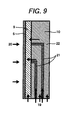
- FIG. 9 is a longitudinal sectional view showing a modified example of the invention.
- FIG. 10 is a longitudinal sectional view showing a modified example of the invention.
- FIG. 11 is a cross sectional view showing a modified example of the invention.
- a flat tube type fuel cell comprises:
- FIG. 1 shows a schematic view of a flat tube double-sided power generation type cell.
- a cell 5 comprises a solid electrolyte 1 , an anode 2 (fuel electrode) formed on an outer surface of the solid electrolyte 1 , a cathode 3 (air electrode) formed on an inner surface of the solid electrolyte 1 , and an interconnector 4 for taking out a current from the cathode 3 .
- a current-collecting electrode 6 is provided around the cell 5 .
- a current of the cell 5 flows from the anode 2 to the cathode 3 by way of the solid electrolyte 1 . Further, it flows from the cathode 3 to the interconnector 4 for taking out the current. Since most of the current of the anode 2 flows in the circumferential direction, the current path is increased. In order to prevent the increased current path from becoming a large resistor factor, the current-collecting electrode 6 serves to increase a cross-sectional area of the current path in an auxiliary manner. Incidentally also in the cathode, a current path in the circumferential direction is present although it is not so larger in the anode 2 . An air-feeding hole 7 is formed inside of the cathode 3 to feed air as an oxidizing agent, and thereby air region through which air flows is formed. On the other hand, the fuel flows along an outer circumference of the cell 5 to form a fuel region.
- FIG. 1 shows a case of a cell in which the anode is formed on the outer side of the flat tube type
- a similar phenomenon as to the current path occurs also even in the case of a cell where the cathode is formed on the outside of the flat tube type.
- the following description is to be made to a case where the anode is formed on the outside of the cell, and it is specified to an anode of the flat tube double-sided power generation type cell.
- the flow of the fuel in the current-collecting electrode of the flat tube cell is shunted into a flow toward the cell and a flow directly flowing to the downstream of the fuel (in the direction of exit).
- the thickness of the anode electrode is decreased to provide the current-collecting electrode with a role of the anode electrode to thereby increase the power generation amount of the cell.
- FIG. 2 shows a cross sectional view of a flat tube double-sided power generation type cell as an example of the present invention.
- An anode (fuel electrode) 2 is formed on the outer surface of the solid electrolyte 1
- a cathode (air electrode) 3 is formed on the inner surface of the same 1
- interconnectors 4 for taking out the current of the cathode are disposed at two positions in the outer surface of the cell.
- the anode 2 is disposed between the interconnectors 4 provided at two positions in the same manner as portions in the cell.
- the solid electrolyte 1 is in a flat tube shape with a bottom, and its material is yttrium stabilized zirconia (YSZ).
- the anode 2 is made of a porous cermet (sintered body of a metal ceramic) comprising nickel and YSZ.
- the cathode 3 is made of lanthanum manganate.
- the interconnectors 4 are made of a lanthanum chlomide.
- the fuel flows through the outside of the cell.
- the oxidizing agent (air) flows through air feeding holes 7 at three positions inside the cathode.
- the current-collecting electrode 6 is filled in a fuel region 8 on the outside of the cell through which the fuel flows.
- the current-collecting electrode 6 is comprised of an inner current-collecting electrode 9 adjacent to the anode and an outer current-collecting electrode 10 placed outside the inner current-collecting electrode 9 .
- FIG. 3 shows a portion of a longitudinal cross section of the flat tube double-sided power generation type cell as an embodiment of the invention.
- FIG. 3 shows the state of a flow of the fuel 19 .
- the size of arrows schematically shows the level of the flow rate. That is, the flow rate is comparatively higher in the outer current-collecting electrode 10 and the flow rate is comparatively lower in the inner current-collecting electrode 9 .
- the fuel 19 in the outer current-collecting electrode 10 does not have cell reaction in the lower portion and flows to the upper portion of the cell at the downstream. That is, the fuel not having the cell reaction (not used fuel) can be fed as far as the upper portion of the cell (downstream) and the cell reaction occurs uniformly over the entire surface of the cell 5 .
- the outer current-collecting electrode 10 mainly constitutes a flow path for feeding the fuel in the axial direction of the cell. Further, the outer current-collecting electrode 10 also functions as a current path. Accordingly, the conditions required for the outer current-collecting electrode 10 are preferably as follows. That is,
- the fuel gas can flow more easily compared with that in the inner current-collecting electrode 9 (with low flow resistance);
- the inner current-collecting electrode 9 mainly has a role of transporting the fuel fed to the outer current-collecting electrode 10 into the anode 2 . Further, the inner current-collecting electrode 9 functions also as a current path. Accordingly, the conditions required for the inner current-collecting electrode 9 are preferably as follows. That is,
- a porous member having through pores for example, a three-dimensional mesh porous member can be used.
- the flow rate increases more as the porosity is larger and the strand diameter constituting the porous member is larger assuming that the differential pressure on the porous layer with a length of l is identical.
- the flow resistance increases more as the porosity is smaller and the wire diameter is smaller.
- the gas flows more easily in the outer current-collecting electrode 10 compared with the inner current-collecting electrode 9 and it is preferable to flow at a fast flow rate.
- the outer current-collecting electrode 10 used in this case had a porosity of about 95% and the strand diameter of about 10 ⁇ m.
- those having a porosity of about 90% and a strand diameter of about 10 ⁇ m was used for the inner current-collecting electrode 9 . This can make the flow rate in the outer current-collecting electrode 10 higher by about one digit compared with the flow rate in the inner current-collecting electrode 9 .
- the difference of the flow rate may be at least about from 1.2 to 1.5.
- the electroconductivity is high as shown by the required condition (2) above.
- a nickel material was used both for the inner current-collecting electrode 9 and the outer current-collecting electrode 10 .
- Nickel was used as a three-dimensional mesh porous member. It may also be a stainless steel, nickel-based alloy, etc.
- a ceramic material may also be used not being restricted to metal materials.
- the current path is enlarged, thereby contributing to the lowering of the internal resistance.
- the cell reaction is shown here.
- a method of reforming a hydrocarbon type fuel to form a reformed gas containing hydrogen is to be described in the case of methane as example of the hydrocarbon type fuel.
- methane and steams are reacted (reforming reaction) to generate hydrogen mainly according to the reaction of the following formula (1).
- the reaction of forming hydrogen from a hydrocarbon type fuel is an endothermic reaction, heat has to be supplied for keeping the reaction and, generally, the reforming catalyst has to be kept at about 600 to 800° C.
- a current in the cell of this embodiment is schematically shown in FIG. 4 .
- the current path is indicated by arrows 11 .
- the current of the cell passes from the outer current-collecting electrode 10 to the inner current-collecting electrode 9 , flows by way of an anode 2 and a solid electrolyte 1 into a cathode 3 and, further, flows from the cathode 3 to interconnectors 4 and is then taken out to the outside.
- the current from the outer current-collecting electrode 14 and the inner current-collecting electrode 13 disposed between the two interconnectors, and from the anode 12 also flows through the similar path to the inter connectors 4 and is then taken out to the outside.
- the anode 2 and the outer current-collecting electrode 14 are electrically connected at the respective adjacent cells as shown in FIG. 5 .
- the interconnector 4 is circumferentially divided at two positions and also divided longitudinally at two positions but it may be divided at three or more portions with no problem.
- FIG. 6 shows a modified example of this embodiment.
- a ceramic porous member that can be insulated electrically is used as the outer current-collecting electrode 15 in FIG. 1 .
- the ceramic porous member that can be insulated electrically for the outer current-collecting electrode 15 since electrical connection with the anode of an adjacent cell can be avoided upon serial connection of the cells, this is extremely effective in a case of connecting a plurality of cells in series or parallel.
- FIG. 7 shows a modified example of this embodiment.
- a metal mesh or ceramic mesh that can be insulated electrically is used as the outer current-collecting electrode 17 of FIG. 1 .
- a same metal mesh was used also for the inner current-collecting electrode 16 .
- a coarse mesh of about #30 was used for the outer current-collecting electrode 17 and a fine mesh of about #100 was used for the inner current-collecting electrode 16 .
- FIG. 8 shows a modified example of the invention.
- the outer current-collecting electrode in FIG. 1 was removed to provide a fuel feed area 18 . While the flow resistance is decreased but the electric resistance increases compared with FIG. 1 .
- FIG. 9 shows a modified example of the invention.
- the illustrated example has fuel-feeding holes 21 and anode-side fuel-feeding holes 22 as the fuel gas flow channels in the outer current-collecting electrode 10 and the inner current-collecting electrode 9 .
- the fuel-feeding holes 21 serve to flow the fuel gas mainly in the axial direction of the cell, while the anode-side fuel-feeding holes 22 serves to flow the fuel gas in the radial direction of the cell. Provision of the flow channels enables to feed the unused fuel furthermore to the downstream by which the fuel is fed to the entire surface of the cell 5 making the cell reaction uniform.
- FIG. 11 shows a cross sectional view of this embodiment.
- FIG. 10 shows a modified example of this embodiment.
- fuel-feeding holes 21 and anode-side fuel-feeding holes 22 as gas flow channels are disposed in the inner current-collecting electrode 9 .
- the fuel-feeding holes 21 serve to flow the fuel gas mainly in the axial direction of the cell
- the anode-side fuel-feeding holes 22 serve to flow the fuel gas in the radial direction of the cell.
- Provision of the flow channels enables to feed the unused fuel further to the downstream and the fuel is fed to the entire surface of the cell 5 to make the cell reaction uniform. Since such fuel gas feeding channels can be also used for the axial feeding of the fuel gas, the outer current-collecting electrode 10 was removed. This can reduce the internal resistance.
- the present invention can provide the same effect also in the cell structure in which the outside of the flat tube double-sided power generation type cell is provided with the cathode.
- the cell shape is not restricted to the flat tube shape but the invention is applicable also to a cell of an oval shape in cross section or a cell of a cuboidal, rectangular or cylindrical shape with similar effect, the shape is not restricted to the flat tube shape.
- the energy efficiency can be improved.
- the cell performance can further be improved by providing the current-collecting electrode not only to the anode but also to the cathode.
Abstract
-
- means (1) for optimizing the constitution of an current-collecting electrode thereby making the flow of fuel or air uniform over the entire region, and
- means (2) for dividing the current-collecting electrode into two regions thereby shunting the flow of the fuel into a flow directing to the anode of the cell and a flow directly directing to the downstream, for increasing the power generation amount in the cell, the means being applicable also to a cell of a cylindrical shape.
Description
V=ε 0 3 D 2 ΔP/{80μ(1−ε0)2 }l (1)
in the equation, ε0 represents a porosity, D represents a diameter of strand constituting the porous member, l represents the length of a porous layer, ΔP represents a differential pressure between the upstream and the downstream of the porous layer, and μ represents the viscosity of a flood. Accordingly, the flow rate increases more as the porosity is larger and the strand diameter constituting the porous member is larger assuming that the differential pressure on the porous layer with a length of l is identical. Naturally, the flow resistance increases more as the porosity is smaller and the wire diameter is smaller.
CH4+H2O=CO+3H2 (1)
CO+H2O=CO2+H2 (2)
H2+½O2=H2O (3)
CO+½O2=CO2 (4)
Claims (10)
Applications Claiming Priority (2)
| Application Number | Priority Date | Filing Date | Title |
|---|---|---|---|
| JP2006185074A JP5176294B2 (en) | 2006-07-05 | 2006-07-05 | Fuel cell |
| JP2006-185074 | 2006-07-05 |
Publications (2)
| Publication Number | Publication Date |
|---|---|
| US20080008922A1 US20080008922A1 (en) | 2008-01-10 |
| US8206867B2 true US8206867B2 (en) | 2012-06-26 |
Family
ID=38919469
Family Applications (1)
| Application Number | Title | Priority Date | Filing Date |
|---|---|---|---|
| US11/657,691 Expired - Fee Related US8206867B2 (en) | 2006-07-05 | 2007-01-25 | Fuel cell |
Country Status (2)
| Country | Link |
|---|---|
| US (1) | US8206867B2 (en) |
| JP (1) | JP5176294B2 (en) |
Cited By (1)
| Publication number | Priority date | Publication date | Assignee | Title |
|---|---|---|---|---|
| US20120070762A1 (en) * | 2009-04-20 | 2012-03-22 | Jong Shik Chung | Stack for a solid oxide fuel cell using a flat tubular structure |
Families Citing this family (3)
| Publication number | Priority date | Publication date | Assignee | Title |
|---|---|---|---|---|
| JP5177847B2 (en) * | 2007-12-17 | 2013-04-10 | 日本碍子株式会社 | Electrochemical equipment |
| JP5192301B2 (en) * | 2008-06-30 | 2013-05-08 | 株式会社日立製作所 | Solid oxide fuel cell and method for producing the same |
| KR101367068B1 (en) * | 2011-12-28 | 2014-02-25 | 삼성전기주식회사 | Bimetal current collecting contact member and fuel cell apparatus with the same |
Citations (4)
| Publication number | Priority date | Publication date | Assignee | Title |
|---|---|---|---|---|
| US4894297A (en) * | 1988-12-07 | 1990-01-16 | Westinghouse Electric Corp. | Electrochemical generator apparatus containing modified fuel electrodes for use with hydrocarbon fuels |
| US6766817B2 (en) | 2001-07-25 | 2004-07-27 | Tubarc Technologies, Llc | Fluid conduction utilizing a reversible unsaturated siphon with tubarc porosity action |
| JP2005166527A (en) | 2003-12-04 | 2005-06-23 | Kyocera Corp | Fuel battery cell and fuel battery |
| US7285355B2 (en) | 2000-04-26 | 2007-10-23 | Quallion Llc | Battery |
Family Cites Families (10)
| Publication number | Priority date | Publication date | Assignee | Title |
|---|---|---|---|---|
| DK0788175T3 (en) * | 1996-02-02 | 2000-07-10 | Sulzer Hexis Ag | High temperature fuel cell with a thin film electrolyte |
| JPH10172590A (en) * | 1996-12-12 | 1998-06-26 | Fuji Electric Corp Res & Dev Ltd | Solid electrolyte type fuel cell |
| JP3340362B2 (en) * | 1997-10-01 | 2002-11-05 | 関西電力株式会社 | Cylindrical solid oxide fuel cell |
| JP3841149B2 (en) * | 2001-05-01 | 2006-11-01 | 日産自動車株式会社 | Single cell for solid oxide fuel cell |
| JP4811622B2 (en) * | 2001-05-01 | 2011-11-09 | 日産自動車株式会社 | Solid oxide fuel cell |
| JP4552371B2 (en) * | 2002-03-11 | 2010-09-29 | 三菱マテリアル株式会社 | Solid oxide fuel cell |
| JP4646102B2 (en) * | 2003-04-16 | 2011-03-09 | 日本特殊陶業株式会社 | Solid oxide fuel cell |
| JP4682511B2 (en) * | 2003-12-02 | 2011-05-11 | 日産自動車株式会社 | Solid oxide fuel cell |
| JP2005174846A (en) * | 2003-12-15 | 2005-06-30 | Nissan Motor Co Ltd | Fuel battery block and its manufacturing method |
| JP2005251562A (en) * | 2004-03-04 | 2005-09-15 | Nissan Motor Co Ltd | Solid oxide fuel cell, cell therefor and cell board |
-
2006
- 2006-07-05 JP JP2006185074A patent/JP5176294B2/en not_active Expired - Fee Related
-
2007
- 2007-01-25 US US11/657,691 patent/US8206867B2/en not_active Expired - Fee Related
Patent Citations (6)
| Publication number | Priority date | Publication date | Assignee | Title |
|---|---|---|---|---|
| US4894297A (en) * | 1988-12-07 | 1990-01-16 | Westinghouse Electric Corp. | Electrochemical generator apparatus containing modified fuel electrodes for use with hydrocarbon fuels |
| US7285355B2 (en) | 2000-04-26 | 2007-10-23 | Quallion Llc | Battery |
| US6766817B2 (en) | 2001-07-25 | 2004-07-27 | Tubarc Technologies, Llc | Fluid conduction utilizing a reversible unsaturated siphon with tubarc porosity action |
| US6918404B2 (en) | 2001-07-25 | 2005-07-19 | Tubarc Technologies, Llc | Irrigation and drainage based on hydrodynamic unsaturated fluid flow |
| US7066586B2 (en) | 2001-07-25 | 2006-06-27 | Tubarc Technologies, Llc | Ink refill and recharging system |
| JP2005166527A (en) | 2003-12-04 | 2005-06-23 | Kyocera Corp | Fuel battery cell and fuel battery |
Non-Patent Citations (1)
| Title |
|---|
| Email from Elson Silva, dated Apr. 23, 2008, subject IDS request for US 20080008922. |
Cited By (2)
| Publication number | Priority date | Publication date | Assignee | Title |
|---|---|---|---|---|
| US20120070762A1 (en) * | 2009-04-20 | 2012-03-22 | Jong Shik Chung | Stack for a solid oxide fuel cell using a flat tubular structure |
| US9608285B2 (en) * | 2009-04-20 | 2017-03-28 | Postech Academy-Industry Foundation | Stack for a solid oxide fuel cell using a flat tubular structure |
Also Published As
| Publication number | Publication date |
|---|---|
| JP2008016268A (en) | 2008-01-24 |
| JP5176294B2 (en) | 2013-04-03 |
| US20080008922A1 (en) | 2008-01-10 |
Similar Documents
| Publication | Publication Date | Title |
|---|---|---|
| US7892684B2 (en) | Heat exchanger for fuel cell stack | |
| US8389180B2 (en) | Electrolytic/fuel cell bundles and systems including a current collector in communication with an electrode thereof | |
| US8709674B2 (en) | Fuel cell support structure | |
| EP3346532A1 (en) | Fuel cell module and fuel cell device | |
| US9997797B2 (en) | Electrochemical reaction unit and fuel cell stack | |
| US7972742B2 (en) | Tube type fuel cell to decrease current path length | |
| US9761895B2 (en) | Cell stack device, fuel cell module, fuel cell device, and method of fabricating cell stack device | |
| US8206867B2 (en) | Fuel cell | |
| JP6037749B2 (en) | Fuel cell module | |
| JP4897273B2 (en) | Fuel cell | |
| JP4758074B2 (en) | Fuel cell assembly and fuel cell | |
| EP3358664A1 (en) | Fuel cell reformer, fuel cell module, and fuel cell device | |
| US11251446B2 (en) | Fuel cell system | |
| JP2010182425A (en) | Solid oxide fuel cell | |
| JP4329345B2 (en) | Internal reforming fuel cell | |
| JPH034454A (en) | Solid electrolyte type fuel cell module | |
| JP2005294152A (en) | Solid oxide fuel cell | |
| JP4706191B2 (en) | Solid oxide fuel cell | |
| JP2005203257A (en) | Solid oxide fuel cell | |
| US20240018668A1 (en) | Methane production system | |
| US20230057533A1 (en) | Fuel cell stack | |
| JP5192301B2 (en) | Solid oxide fuel cell and method for producing the same | |
| JP2023072926A (en) | Electrolysis cell and cell stack device |
Legal Events
| Date | Code | Title | Description |
|---|---|---|---|
| AS | Assignment |
Owner name: HITACHI, LTD., JAPAN Free format text: ASSIGNMENT OF ASSIGNORS INTEREST;ASSIGNORS:TOKOI, HIROMI;KOBAYASHI, NARIYOSHI;TAKAHASHI, KAZUO;AND OTHERS;REEL/FRAME:019132/0704 Effective date: 20070227 |
|
| STCF | Information on status: patent grant |
Free format text: PATENTED CASE |
|
| FEPP | Fee payment procedure |
Free format text: PAYOR NUMBER ASSIGNED (ORIGINAL EVENT CODE: ASPN); ENTITY STATUS OF PATENT OWNER: LARGE ENTITY |
|
| FPAY | Fee payment |
Year of fee payment: 4 |
|
| FEPP | Fee payment procedure |
Free format text: MAINTENANCE FEE REMINDER MAILED (ORIGINAL EVENT CODE: REM.); ENTITY STATUS OF PATENT OWNER: LARGE ENTITY |
|
| LAPS | Lapse for failure to pay maintenance fees |
Free format text: PATENT EXPIRED FOR FAILURE TO PAY MAINTENANCE FEES (ORIGINAL EVENT CODE: EXP.); ENTITY STATUS OF PATENT OWNER: LARGE ENTITY |
|
| STCH | Information on status: patent discontinuation |
Free format text: PATENT EXPIRED DUE TO NONPAYMENT OF MAINTENANCE FEES UNDER 37 CFR 1.362 |
|
| FP | Lapsed due to failure to pay maintenance fee |
Effective date: 20200626 |