US8220881B2 - Cable management systems having access doors connected thereto via latch/hinge assemblies - Google Patents
Cable management systems having access doors connected thereto via latch/hinge assemblies Download PDFInfo
- Publication number
- US8220881B2 US8220881B2 US12/268,721 US26872108A US8220881B2 US 8220881 B2 US8220881 B2 US 8220881B2 US 26872108 A US26872108 A US 26872108A US 8220881 B2 US8220881 B2 US 8220881B2
- Authority
- US
- United States
- Prior art keywords
- latch
- door
- support structure
- opening
- receiving assembly
- Prior art date
- Legal status (The legal status is an assumption and is not a legal conclusion. Google has not performed a legal analysis and makes no representation as to the accuracy of the status listed.)
- Active, expires
Links
- 230000000712 assembly Effects 0.000 title claims abstract description 84
- 238000000429 assembly Methods 0.000 title claims abstract description 84
- 238000004891 communication Methods 0.000 claims abstract description 44
- 125000006850 spacer group Chemical group 0.000 claims description 20
- 230000001154 acute effect Effects 0.000 claims description 6
- 230000013011 mating Effects 0.000 description 15
- 230000007246 mechanism Effects 0.000 description 7
- 239000000463 material Substances 0.000 description 5
- 230000009471 action Effects 0.000 description 3
- 230000006835 compression Effects 0.000 description 3
- 238000007906 compression Methods 0.000 description 3
- 238000012986 modification Methods 0.000 description 3
- 230000004048 modification Effects 0.000 description 3
- 230000007704 transition Effects 0.000 description 3
- 208000031481 Pathologic Constriction Diseases 0.000 description 2
- 239000000853 adhesive Substances 0.000 description 2
- 230000001070 adhesive effect Effects 0.000 description 2
- 239000002184 metal Substances 0.000 description 2
- 238000013459 approach Methods 0.000 description 1
- 238000010276 construction Methods 0.000 description 1
- 230000008878 coupling Effects 0.000 description 1
- 238000010168 coupling process Methods 0.000 description 1
- 238000005859 coupling reaction Methods 0.000 description 1
- 238000010586 diagram Methods 0.000 description 1
- 230000005484 gravity Effects 0.000 description 1
- 230000003993 interaction Effects 0.000 description 1
- 230000014759 maintenance of location Effects 0.000 description 1
- 238000000034 method Methods 0.000 description 1
- 239000012811 non-conductive material Substances 0.000 description 1
- 230000008569 process Effects 0.000 description 1
- 230000000284 resting effect Effects 0.000 description 1
- 230000000717 retained effect Effects 0.000 description 1
Images


Classifications
-
- H—ELECTRICITY
- H05—ELECTRIC TECHNIQUES NOT OTHERWISE PROVIDED FOR
- H05K—PRINTED CIRCUITS; CASINGS OR CONSTRUCTIONAL DETAILS OF ELECTRIC APPARATUS; MANUFACTURE OF ASSEMBLAGES OF ELECTRICAL COMPONENTS
- H05K7/00—Constructional details common to different types of electric apparatus
- H05K7/18—Construction of rack or frame
- H05K7/186—Construction of rack or frame for supporting telecommunication equipment
-
- E—FIXED CONSTRUCTIONS
- E05—LOCKS; KEYS; WINDOW OR DOOR FITTINGS; SAFES
- E05D—HINGES OR SUSPENSION DEVICES FOR DOORS, WINDOWS OR WINGS
- E05D15/00—Suspension arrangements for wings
- E05D15/48—Suspension arrangements for wings allowing alternative movements
- E05D15/50—Suspension arrangements for wings allowing alternative movements for opening at either of two opposite edges
- E05D15/505—Suspension arrangements for wings allowing alternative movements for opening at either of two opposite edges by radial separation of the hinge parts at the hinge axis
-
- H—ELECTRICITY
- H04—ELECTRIC COMMUNICATION TECHNIQUE
- H04Q—SELECTING
- H04Q1/00—Details of selecting apparatus or arrangements
- H04Q1/02—Constructional details
- H04Q1/021—Constructional details using pivoting mechanisms for accessing the interior of the apparatus
-
- H—ELECTRICITY
- H04—ELECTRIC COMMUNICATION TECHNIQUE
- H04Q—SELECTING
- H04Q1/00—Details of selecting apparatus or arrangements
- H04Q1/02—Constructional details
- H04Q1/06—Cable ducts or mountings specially adapted for exchange installations
-
- E—FIXED CONSTRUCTIONS
- E05—LOCKS; KEYS; WINDOW OR DOOR FITTINGS; SAFES
- E05Y—INDEXING SCHEME RELATING TO HINGES OR OTHER SUSPENSION DEVICES FOR DOORS, WINDOWS OR WINGS AND DEVICES FOR MOVING WINGS INTO OPEN OR CLOSED POSITION, CHECKS FOR WINGS AND WING FITTINGS NOT OTHERWISE PROVIDED FOR, CONCERNED WITH THE FUNCTIONING OF THE WING
- E05Y2900/00—Application of doors, windows, wings or fittings thereof
- E05Y2900/20—Application of doors, windows, wings or fittings thereof for furnitures, e.g. cabinets
- E05Y2900/208—Application of doors, windows, wings or fittings thereof for furnitures, e.g. cabinets for metal cabinets
Definitions
- two or more back panels are mounted in a side-by-side, spaced apart arrangement.
- a spacer bracket is mounted in the space between the back panels.
- the spacer bracket may be secured to the wall and/or to one or both of the back panels.
- the spacer bracket defines a cord trough through which cords may be routed that connect connection blocks of one of the back panels with connection blocks of the other back panel.
- a door panel is mounted on the spacer bracket to protect and hide the cords in the cord trough.
- Stand alone communications cable management cabinets are also provided that may similarly include one or more door panels that protect and hide the cords and cables that are routed through a cord trough in the interior of the cabinet.
- FIG. 6 is a perspective view of the door assembly of FIG. 1 in position in a wall-mounted communications system.
- FIG. 9 is an enlarged rear perspective view of the door assembly of FIG. 7 with the handle in an extended position.
- FIG. 12 is an enlarged front perspective view of the door assembly of FIG. 7 showing that extension of both handles allows the door assembly to be removed from its mounted position.
- FIG. 14 is a top view of a latch receiving assembly of FIG. 13 with the latch pin of the door assembly of FIG. 1 outside of the latch receiving assembly.
- FIG. 15 is a top view of a latch receiving assembly of FIG. 13 with the latch pin of the door assembly of FIG. 1 in the process of being received within the latch receiving assembly.
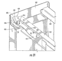
- FIG. 21 is a partial perspective view of the door assembly of FIG. 17 mounted on a support structure that includes a latch receiving assembly according to certain embodiments of the present invention.
- FIG. 22 is a top view of the door assembly and support structure of FIG. 21 .
- FIG. 23 is a partial perspective view of the door assembly and support structure of FIG. 21 with the door partially opened.
- FIG. 26 is a front perspective view of a terminal block panel system according to embodiments of the present invention including the door assembly of FIG. 1 .
- spatially relative terms such as “under”, “below”, “lower”, “over”, “upper” and the like, may be used herein for ease of description to describe one element or feature's relationship to another element(s) or feature(s) as illustrated in the figures. It will be understood that the spatially relative terms are intended to encompass different orientations of the device in use or operation in addition to the orientation depicted in the figures. For example, if the device in the figures is turned over, elements described as “under” or “beneath” other elements or features would then be oriented “over” the other elements or features. Thus, the exemplary term “under” can encompass both an orientation of over and under. The device may be otherwise oriented (rotated 90 degrees or at other orientations) and the spatially relative descriptors used herein interpreted accordingly.
- communications cable management systems are provided that include door assemblies.
- the communications cable management systems may comprise, for example, one or more communications racks, cabinets or wall-mounted systems upon which one or more door assemblies are mounted.
- the handles 16 a , 16 b may be generally U-shaped, having two arms 18 that are bridged by a bi-arcuate grasping portion 19 that protrudes away from the door body 12 to facilitate grasping by a user.
- the handles 16 a , 16 b may be mirror images of each other, and hence only handle 16 a is described below.
- handle 16 a includes a pivot base 20 a , 20 b at the end of each respective arm 18 .
- the pivot bases are located in recesses 14 c in the side lips 14 .
- Each pivot base 20 a , 20 b includes a cammed surface 22 that wraps helically around the pivot base 20 a , 20 b to form a helical ramp that faces downwardly.
- the back plate 26 a includes a series of ribs 27 that have apertures (not shown) that receive the handle pins 24 a - 24 d of the associated handle 16 a . Also, two stops 29 are positioned to rest against the ends of the handle pins 24 a , 24 d to maintain the handle 16 a in place.
- a spring 30 ( FIG. 3 ) surrounds each of the handle pins 24 a , 24 c and is mounted to a rib 27 to bias the handle 16 a toward a closed position, in which the handle 16 a resides in the recess 17 of the door body 12 .
- each of two toggle arms 32 a , 32 b are pivotally attached to a mounting platform 31 on each back plate 26 a , 26 b at, respectively, pivots 34 a , 34 b , such that the toggle arms 32 a , 32 b can rotate about respective axes A 3 , A 4 that are normal to the door body 12 .
- each toggle arm 32 a , 32 b includes a cam interface post 36 that extends toward and contacts the cammed surface 22 of the adjacent pivot base 20 a , 20 b of the handle 16 a.
- latch bar 40 a two generally vertically-disposed mirror image latch bars 40 a , 40 b (only one of which, latch bar 40 a , will be described herein) are positioned inboard of the handles 16 a , 16 b , each overlying a portion of its respective back plate 26 a , 26 b .
- the latch bar 40 a includes mounting apertures 41 that receive latch bar retainers 42 that project from the back plate 26 a .
- the mounting apertures 41 are of sufficient length that the latch bar 40 a can move vertically over a short distance along an axis A 5 .
- the latch bar 40 a includes a top flange 45 that extends laterally from the upper end of the latch bar 40 a .
- a latch structure in the form of a latch pin 46 extends downwardly from the top flange 45 .
- the latch pin 46 is received in an aperture or compartment defined in a locator or guide feature 46 a that protrudes from the back of the back plate 26 a .
- a bottom flange 47 extends laterally from the lower end of the latch bar 40 a
- a latch structure in the form of a latch pin 48 extends downwardly therefrom through an aperture or compartment in a locator feature 48 a that protrudes from the back of the back plate 26 b .
- the door assembly 10 may be mounted via the pins 46 , 48 on two communications racks 100 , 102 in order to cover a cable trough 104 between the racks 100 , 102 .
- the cable trough 104 may be any channel or partially enclosed area that houses communications cables/cords.
- the sides of the racks 100 , 102 define a cable trough 104 therebetween.
- the presence of the latch pins 46 , 48 prevents the door assembly 10 from opening inadvertently. In this position (the “closed position”) as shown in FIG.
- the door assembly 10 is latched closed on both the left and right sides and serves as a fixed front wall for a portion of the trough 104 .
- the door assembly 10 thus serves to hide, protect and/or contain cords in the trough 104 .
- the latch pins 46 , 48 of the latch bar 40 a are disposed in a latched position wherein they engage respective mating latch receiving assemblies that are mounted on the rack 100 and the latch pins 46 , 48 of the latch bar 40 b are disposed in a latched position wherein they engage respective latch receiving assemblies that are mounted on the rack 102 .
- Latch receiving assemblies 450 according to embodiments of the present invention that may be used to receive the latch pins 46 , 48 are described below with respect to FIGS. 13-16 .
- the handles 16 a , 16 b are in a retracted position in which the arms 18 of each handle 16 a , 16 b reside in their respective recesses 17 and are generally parallel with the door body 12 .
- the pivot bases 20 a , 20 b of the handles 16 a , 16 b are oriented such that the upper ends of the cammed surfaces 22 face rearwardly and contact the cam interface pins 36 of the toggle arms 32 a , 32 b (see FIG. 2 ).
- the handles 16 a , 16 b are urged toward this retracted position by the springs 30 acting on the handle pins 24 a , 24 c.
- An operator can open the door assembly 10 from either the left side or the right side to access the trough 104 without removing the door assembly 10 from the racks 100 , 102 .
- a user simply grasps the appropriate handle 16 a , 16 b and rotates it so that the grasping portion 19 moves away from the center of door body 12 toward a side edge of door body 12 .
- the handle 16 a and the linkage between the handle 16 a and the pins 46 , 48 serve as an actuator to transition the pins 46 , 48 from their latched positions to their unlatched positions. More particularly, as is apparent from FIGS.
- rotation of the handle 16 a causes the pivot bases 20 a , 20 b and handle pins 24 a , 24 b , 24 c , 24 d to rotate about the axis A 1 .
- the cammed surface 22 of each rotates also, such that eventually the lower end of each cammed surface 22 faces rearwardly and is in contact with the cam interface pin 36 (rotation of the handle 16 a ceases when a stepped surface 37 on the pivot base 20 a contacts the cam interface pin 36 ).
- the door assembly 10 can be pivoted about the axis A 7 (i.e., the axis of the pins 46 , 48 of the latch bar 40 b ) on the right side of the door assembly 10 to an open position (see FIG. 10 ).
- the pins 46 , 48 of the latch bar 40 b and the latch receiving assemblies of the rack 102 in which the pins 46 , 48 are received serve as a hinge assembly, and the door assembly 10 can be opened as a right side hinged door.
- an operator can also completely remove the door assembly 10 by simultaneously moving both handles 16 a , 16 b to their respective extended positions. Extension of both handles 16 a , 16 b draws the pins 46 , 48 on both sides of the door assembly 10 from their respective latch receiving assemblies 450 (i.e., into their unlatched positions). The completely removed door assembly 10 can be returned to its closed position ( FIG. 6 ) by pushing the door body 12 back into place so that the latch pins 46 , 48 are received by their respective latch receiving assemblies on racks 100 , 102 .
- the latch receiving assembly 450 may comprise a latch member 460 .
- the latch member 460 includes a rear portion 462 and a forward portion 464 .
- the rear portion 462 is mounted to a support member 440 of support structure 435 via a rivet, pin, or other fastener 480 that may act as a pivot.
- the forward portion 464 includes a hook 466 .
- the support member 440 includes a slot 445 at one end thereof that is configured to receive a respective one of the latch pins 46 of door assembly 10 .
- the latch receiving assembly 450 further comprises a spring 470 .
- the spring 470 is connected between the support member 440 and the latch member 460 , and is configured to bias the forward portion 464 of the latch member 460 toward the closed position in which the hook 466 of latch member 460 captures the latch pin 46 within the slot 445 .
- the spring 470 may merely operate as a return system that returns the latch member to its closed position, and need not be configured to help hold the latch member 460 in its closed position. Accordingly, in some embodiments, a light spring can be used that has a low resistance level.
- the latch member 460 when the latch member 460 is in the closed position, the front edge 468 of hook 466 is angled with respect to the longitudinal axis of slot 445 . As will be discussed in further detail below, the latch pin 46 may engage the angled front edge 468 of hook 466 when door assembly 10 is moved to its closed position.
- each of the latch pins 46 , 48 are moved upwardly so as to no longer be captured by the hook 466 within the slot 445 ).
- Each latch member 460 remains in its closed position of FIG. 13 as the handle 16 b is rotated and the latch pins 46 , 48 are retracted.
- the coupling structure between the handles 16 a , 16 b and the latch pins 46 , 48 is configured so that the latch pins 46 , 48 are biased toward their latched positions. Thus, when the handles 16 a , 16 b are not rotated, the latch pins 46 , 48 are in their latched positions where they engage their corresponding latch members 460 .
- FIG. 14 illustrates the latch member 460 in its closed position, except in FIG. 14 , the latch pin 46 is outside of the slot 445 of support member 440 , as would be the case when the door body 12 is open.
- the latch pins 46 , 48 are likely to be in their latched (lowered) positions (because typically an operator will not be holding the handle 16 b open when closing the door body 12 ).
- the latch pin 46 , 48 approaches the hook 466 of its respective latch member 460 , the latch member 460 is in its closed position.
- FIG. 15 as the door 10 is closed, the latch pin 46 engages the angled front edge 468 of hook 466 .
- the latch pin 46 forces the forward portion 464 of latch member 460 to pivot away from the slot 445 , thereby providing access to the slot 445 for the respective latch pin 46 , 48 .
- the latch pin 46 , 48 can then slide into the slot 445 ( FIG. 15 ).
- the hook 466 biased by the spring 470 , returns to the closed position of FIG. 13 , where the latch pin 46 and the latch receiving assembly 450 can operate as either a latch or as a hinge. It can thus be seen that, in this configuration, the latch member 460 allows the door body 12 to be closed without any manipulation of the handle 16 b required.
- Center back panel 505 covers and protects handle mechanisms 508 , 509 , while the top and bottom back panels 506 , 507 act to hold the latch bars 540 a , 540 b , 541 a , 541 b in their proper positions.
- Center back panel 505 and top and bottom back panels 506 , 507 may be mounted onto and/or adjacent the rear surface of the door body 502 via rivets, adhesive, threaded fasteners or the like.
- a handle 516 a , 516 b is associated with each respective handle mechanism 508 , 509 .
- the handles 516 a , 516 b each fit within a respective recess 517 in the door body 502 .
- the handles 516 a , 516 b may be generally U-shaped, having two arms 518 that are bridged by a grasping portion 519 .
- the handles 516 a , 516 b may be mirror images of each other, and hence only handle 516 a is described below.
- handle 516 a includes a pivot base 520 a , 520 b at the end of each respective arm 518 .
- Pivot base 520 a includes a cammed surface (not visible in FIGS. 17-18 ) that forms a helical ramp that faces downwardly
- pivot base 520 b includes a cammed surface (not visible in FIGS. 17-18 ) that forms a helical ramp that faces upwardly.
- a handle pin 524 extends vertically through the pivot bases 520 a , 520 b .
- the pivot bases 520 a , 520 b may be formed integrally with the remainder of the handle 516 a .
- a pair of cams 532 a , 532 b are mounted to the back of door body 502 and/or to the side lip 504 .
- a first end of cam 532 a extends toward and contacts the cammed surface of the adjacent pivot base 520 a of handle 516 a .
- a first end of cam 532 b similarly extends toward and contacts the cammed surface of the adjacent pivot base 520 b of handle 516 b.
- latch bars 540 a , 540 b , 541 a , 541 b are provided (only the pair of latch bars 540 a , 540 b will be described herein).
- the first end of latch bar 540 a is mounted to a second end of cam 532 a , while the second end of latch bar 540 a is received within a corner bushing 534 that is attached to the top back plate 506 .
- the first end of latch bar 540 b is mounted to a second end of cam 532 b , while the second end of latch bar 540 b is received within a corner bushing 534 that is attached to the bottom back plate 507 .
- the second end of latch bar 540 a comprises a latch structure in the form of an upwardly extending latch pin 546 (note that latch pin 546 may simply comprise the end portion of a rod that forms the latch bar 540 a ).
- the pin 546 is received in an aperture in corner bushing 534 .
- the second end of latch bar 540 b comprises a latch structure in the form of a downwardly extending latch pin 548 (note that latch pin 548 may simply comprise the end portion of a rod that forms the latch bar 540 b ).
- the pin 548 is received in an aperture in corner bushing 534 .
- the latch bars 540 a , 540 b are configured to move a short distance along the vertical axis B 1 that is defined by the latch bars 540 a , 540 b to transition between respective latched and unlatched positions.
- Each latch bar 540 a , 540 b is in its latched position when its respective latch pin 546 , 548 is extended away from the center of door body 502 .
- the latch bars 540 a , 540 b are in their unlatched positions when their respective latch pins 546 , 548 have been moved a short distance along the axis B 1 toward the center of door body 502 .
- Each handle 516 a , 516 b includes a torsion spring 521 a , 521 b (see FIG. 17 ).
- Torsion spring 521 a applies a return force to pivot bases 520 a , 520 b that acts to hold the latch bars 540 a , 540 b in their latched (extended) positions.
- cams 532 a , 532 b are driven toward the center via the action of pivot bases 520 a , 520 b thereon, which acts to move the latch bars 540 a , 540 b to their unlatched positions.
- Rotation of the handle 516 a also acts to load the torsion spring 521 a .
- Handle 516 b works in the same way as handle 516 a , and hence discussion of the operation of handle 516 b will be omitted.
- the axis B 1 defined by the latch bars 540 a , 540 b comprises a pivot axis on which the door assembly 500 can pivot (the latch bars 541 a , 541 b define a second pivot axis B 2 on the opposite side of the door assembly 500 ).
- a spring 532 (see FIG. 19 ) may be mounted to the top back plate 506 .
- the spring 532 may be in compression to urge the latch bar 540 a downwardly.
- Another spring 532 (not shown) may be mounted to the bottom back plate 507 that is in compressions and urges the latch bar 540 b upwardly.
- the door assembly 500 may be mounted onto a support structure 432 by mating each of the latch pins 546 , 548 with respective latch receiving assemblies that are provided on the support structure 432 .
- FIGS. 21-23 illustrate a support structure 432 for the door assembly 500 that includes latch receiving assemblies 400 according to certain embodiments of the present invention.
- the support structure 432 may comprise, for example, a communications rack, cabinet or wall-mounted system. While for purposes of simplicity, FIGS. 13-15 each illustrate only one or two such latch receiving assemblies 400 , it will be appreciated that typically four latch receiving assemblies 400 would be used to mount the door assembly 500 to the support structure 432 , as will be illustrated below with respect to FIGS. 24-25 .
- the latch receiving assemblies 400 may be mounted on, or formed integrally with, the support structure 432 .
- the latch receiving assembly 400 is mounted on the support structure 432 .
- the latch receiving assembly 400 comprises a hinge bracket 410 that is mounted to the support structure 432 via several rivets, screws or other fasteners 430 .
- hinge bracket refers to a structure that is configured to receive a latch so that the latch and the hinge bracket together can operate as a hinge.
- the illustrated embodiment of hinge bracket 410 includes a rear portion 412 that is fixedly mounted to the support structure 432 via the fasteners 430 and a forward portion 414 that is elastically mobile.
- the hinge bracket 410 may be formed from a unitary piece of material such as, for example, a stamped metal plate.
- the forward portion 414 includes an aperture 416 that is configured to receive a respective one of the latch pins 546 of door assembly 500 .
- some or all of the material that is removed to form the aperture 416 may be retained and bent upwardly to form a projection 418 .
- this projection 418 may provide additional structural support to facilitate keeping latch pin 546 within the hinge bracket 410 when the right side of the door assembly 500 (when door assembly 500 is viewed from the front) is in its closed position.
- the forward portion 414 of hinge bracket 410 includes a ramped portion 420 .
- the ramped portion 420 may be positioned so as to form an acute angle with respect to the longitudinal axis of latch pin 546 .
- the ramped portion 420 acts as a striker plate that is engaged by the latch pin 546 when door assembly 10 is closed.
- the forward edge of the support stricture 432 includes a slot 436 (partially visible in FIG. 21 ) that is aligned with and positioned underneath the aperture 416 of hinge bracket 410 .
- the slot 436 provides the latch pin 546 of door assembly 500 access to the aperture 416 .
- the latch pin 546 of latch bar 540 b may be disengaged from the hinge bracket 410 in order to open the right side of door assembly 500 . Thereafter, an operator may return the right side of door assembly 500 to its closed position by pushing the right side of door body 502 toward the support structure 432 . As shown best in FIG. 23 , the latch pin 546 will be in its raised position once the operator releases the handle 516 b . As the door assembly 500 closes, the latch pin 546 of latch bar 540 b eventually comes into contact with the striker plate 420 .
- the striker plate 420 which is part of the elastically mobile portion of hinge bracket 410 , is forced upward by the latch pin 546 .
- the top of the latch pin 546 slides down the striker plate 420 as the striker plate moves upward, until eventually the latch pin 546 slides underneath the striker plate 420 and into the aperture 416 .
- the latch pin 546 ceases to provide an upward force on the hinge bracket 410 , and thus the elastically mobile portion of the hinge bracket 410 snaps back into its resting position, thereby capturing the latch pin 546 in the aperture 416 as is illustrated in FIG. 21 .
- the closing operation is the same for each of the left and right sides of the door assembly 500 . It will be understood that this description likewise applies to closing of the right side of the door assembly 500 .
- the combination of the latch pin 546 and the hinge bracket 410 can act as both a latch and as a hinge.
- a latch pin 546 is provided on both the left and right side of door assembly 500 .
- a mating hinge bracket 410 is provided on both the left and right sides of the support structure 432 .
- FIGS. 22-23 when the door assembly 500 is operated so that the right side of the door opens, the latch pin 546 and mating hinge bracket 410 on the left side of the door assembly act as a hinge, allowing the door to swing open. In this configuration, the latch pin 546 and mating hinge bracket 410 on the light side of the door assembly act as a latch mechanism.
- an operator can activate the latch mechanism to disengage the latch (i.e., pin 546 ), thereby freeing the right side of door assembly 500 so that the door can swing open.
- the latch pin 546 upwardly displaces the hinge bracket 410 until the latch pin 546 is received within the aperture 416 , at which point the hinge bracket 410 falls back into place where the latch pin 546 and hinge bracket 410 can operate as either a closed latch or as a hinge.
- Each of the latch pins 548 cooperate with its respective latch receiving assembly 400 in the same fashion as is discussed above with respect to the latch pins 546 .
- the latch receiving assemblies 400 that cooperate with the latch pins 548 will be mounted upside down as compared to the mounting orientation of the latch receiving assemblies 400 that cooperate with the latch pins 546 .
- the hinge bracket 410 may comprise a fixed member, while the latch pin 546 may be spring loaded.
- the hinge bracket 410 when the pin 546 engages the striker plate 420 as the door assembly 500 is closed, the hinge bracket 410 remains fixed, and the striker plate 420 imparts a downward force on the spring loaded pin 546 .
- This downward force forces the pin down until the latch pin 546 is able to slide past and under the striker plate 420 , at which point the latch pin 546 is received within the aperture 416 .
- the compressive force is removed and the latch pin 546 returns to its latched position where it is captured within the aperture 416 where the latch pin 546 can operate as either a closed latch or as a hinge.
- FIGS. 24 and 25 illustrate a cable management system 600 that uses a pair of the door assemblies 500 .
- the cable management system 600 comprises a pair of cable management towers 602 , 604 .
- Each cable management tower 602 , 604 includes four of the latch receiving assemblies 400 that are discussed above with respect to FIGS. 21-23 .
- Each latch receiving assembly 400 receives a respective one of the four latch pins 546 , 548 of one of the door assemblies 500 to mount that door assembly 500 on each respective cable management tower 602 , 604 .
- the door body 502 on the assembly 500 that is mounted on cable management tower 602 is closed.
- the door handles 516 a , 516 b are in their retracted positions in which the arms 518 of each handle 516 a , 516 b reside in their respective recesses 517 and are generally parallel with the door body 502 .
- the handles 516 a , 516 b are urged toward this retracted positions by the springs 530 that act on the handle pins 524 .
- each latch bar 540 a , 540 b , 541 a , 541 b is likewise held in its extended position when the handles 516 a , 516 b are in their retracted positions.
- An operator can open the door assembly 500 from either the left side or the right side to access the interior of the cable management tower 602 without removing the door assembly 500 from its cable management tower 602 .
- the operator simply grasps the appropriate handle 516 a , 516 b and rotates it so that the grasping portion 519 moves away from the center of door body 502 toward a side edge of door body 502 .
- the handle 516 a and the linkage between the handle 516 a and the pins 546 , 548 serve as an actuator to transition the latch pins 546 , 548 from their latched positions to their unlatched positions.
- rotation of the handle 516 a causes the pivot bases 520 a , 520 b having cammed surfaces to rotate.
- cammed surfaces on the pivot bases 520 a , 520 b rotate, they interact with their respective cams 532 a , 532 b , allowing the respective cams 532 a , 532 b to move toward the center of the door body 502 under the compressive force provided by springs 532 .
- the latch bar 540 a that is attached to cam 532 a and the latch bar 540 b that is attached to cam 532 b likewise move toward the center of the door body 502 (i.e., toward their unlatched positions). Consequently, the latch pins 546 , 548 on the left side of the door assembly 500 are moved out of the apertures 416 of their respective latch receiving assemblies 400 of cable management tower 604 (i.e., into their respective unlatched positions), thereby freeing the left side of the door body 502 (from the vantage point of FIG. 25 ) from the cable management tower 604 .
- the door assembly 500 on cable management tower 604 can be pivoted about the vertical axis defined by the latch bars 541 a , 541 b on the right side of the door assembly 500 to the open position shown in FIG. 25 .
- the pins 546 , 548 and the respective latch receiving assemblies 400 in which the pins 546 , 548 are received serve as a hinge assembly, and the door assembly 500 can be opened as a right side hinged door.
- the right side handle 516 b can be grasped and rotated to open the door assembly as a left side hinged door, or both handles 516 a , 516 b can be grasped and rotated to completely remove door assembly 500 , in a manner similar to the operations discussed above with respect to door assembly 10 .
- latch receiving assemblies 400 are provided on the support structure 432 , it will be appreciated that in other embodiments, the latch receiving assemblies 450 discussed above with respect to FIGS. 13-16 may be used instead on the support structure 432 .
- the support structure 432 could include, for example, two of the latch receiving assemblies 400 and two of the latch receiving assemblies 450 . Additionally, other combinations and/or other types of latch receiving assemblies could also be used.
- FIG. 26 illustrates a terminal block panel system 201 in accordance with further embodiments of the present invention.
- the system 201 includes a spacer bracket assembly 300 and a pair of terminal block panels or patch panel assemblies 200 .
- the panel assemblies 200 may be mounted, for example, on a wall in side-by-side, spaced apart arrangement.
- the spacer bracket assembly 300 is mounted between the panel assemblies 200 .
- the spacer bracket assembly 300 may be secured to the wall and/or one or both of the back panel assemblies 200 .
- the spacer bracket assembly 300 defines a cable trough 328 through which cords may be routed for connecting connection blocks 229 mounted on the back panel assemblies 100 , 200 .
- a door assembly 10 (see FIG.
- the door assembly 10 protects and hides cords in the trough 328 , and the latch system thereof permits selective access to the trough 328 in the manner described above.
- the panel assemblies 200 are exemplary, and thus it will be appreciated that one or both panel assemblies 200 may be configured differently than illustrated and described herein.
- Each panel assembly 200 may comprise, for example, a 900 pair device, a 300 pair device, a 100 pair device, or any other configuration as is known in the art.
- the panel assemblies 200 may be panel assemblies as disclosed in U.S. Pat. No. 6,106,329 to Baker, III et al.
- the panel assembly 200 includes a C-shaped back panel 210 .
- the back panel 210 may comprise, for example, a nonconductive material such as a foamed plastic or polymeric material.
- the back panel 210 may include a rear or securing wall 220 , a pair of opposed side walls 222 , and a series of mounting structures 218 extending along the front edge of each side wall 222 .
- a plurality of connection blocks 229 may be mounted on the mounting structures 218 .
- the back panel 210 may comprise a first panel member 212 and a second panel member 214 that are attached together to form the back panel 210 .
- a cable trough 228 is formed in the area between the side walls 222 , the securing wall 220 and the mounting structures 218 .
- the trough 228 may receive a plurality of communication cables (not shown), some of which may simply extend through the trough, while others are connected to devices such as connection blocks 229 that are mounted to mounting structures 218 .
- Cable management structures such as loop members may be secured to the back panel 210 to hold or guide the cables in the trough 228 .
- Each securing wall 220 may have cut-outs or fastener holes 221 or other features for mounting the back panel 210 to hooks or fasteners, such as a screw, nails, clips or the like that are secured to a wall.
- the spacer bracket 310 may be C-shaped and formed of the same materials and in the same manner as the back panel 210 .
- the spacer bracket 310 includes a rear wall and opposed, spaced apart side walls that define the cord trough 328 . Cable management structures such as retention bars may be secured to the spacer bracket 310 to hold the communications cords in the trough 328 .
- the rear wall may have one or more cut-outs or fastener holes or other features for mounting the spacer bracket 310 on an adjacent back panel 200 or a hook or fastener, such as a screw secured to or mounted on a wall or backboard. Other securing devices such as nails, clips, etc. may be used for securing the spacer bracket 310 to a wall or other structure.
- a pair of left side latch receiving assemblies 450 and a pair of right side latch receiving assemblies 450 are provided on the front of the spacer bracket 310 .
- the latch receiving assemblies 450 define pivot holes or slots within which the respective pins 46 , 48 of the latch bars 40 a , 40 b are slidably and pivotably mounted for vertical reciprocation and rotation about a vertical axis.
Abstract
Description
Claims (17)
Priority Applications (2)
| Application Number | Priority Date | Filing Date | Title |
|---|---|---|---|
| US12/268,721 US8220881B2 (en) | 2007-11-12 | 2008-11-11 | Cable management systems having access doors connected thereto via latch/hinge assemblies |
| PCT/US2008/012690 WO2009064403A1 (en) | 2007-11-12 | 2008-11-12 | Cable management systems having access doors connected thereto via latch/hinge assemblies |
Applications Claiming Priority (2)
| Application Number | Priority Date | Filing Date | Title |
|---|---|---|---|
| US98714007P | 2007-11-12 | 2007-11-12 | |
| US12/268,721 US8220881B2 (en) | 2007-11-12 | 2008-11-11 | Cable management systems having access doors connected thereto via latch/hinge assemblies |
Publications (2)
| Publication Number | Publication Date |
|---|---|
| US20090121092A1 US20090121092A1 (en) | 2009-05-14 |
| US8220881B2 true US8220881B2 (en) | 2012-07-17 |
Family
ID=40622825
Family Applications (1)
| Application Number | Title | Priority Date | Filing Date |
|---|---|---|---|
| US12/268,721 Active 2031-04-10 US8220881B2 (en) | 2007-11-12 | 2008-11-11 | Cable management systems having access doors connected thereto via latch/hinge assemblies |
Country Status (2)
| Country | Link |
|---|---|
| US (1) | US8220881B2 (en) |
| WO (1) | WO2009064403A1 (en) |
Cited By (28)
| Publication number | Priority date | Publication date | Assignee | Title |
|---|---|---|---|---|
| US20110249950A1 (en) * | 2010-04-08 | 2011-10-13 | Erika Guadalupe Chapa Ramirez | Quick release mounting assembly |
| US8879881B2 (en) | 2010-04-30 | 2014-11-04 | Corning Cable Systems Llc | Rotatable routing guide and assembly |
| US8913866B2 (en) | 2010-03-26 | 2014-12-16 | Corning Cable Systems Llc | Movable adapter panel |
| US8953924B2 (en) | 2011-09-02 | 2015-02-10 | Corning Cable Systems Llc | Removable strain relief brackets for securing fiber optic cables and/or optical fibers to fiber optic equipment, and related assemblies and methods |
| US8965168B2 (en) | 2010-04-30 | 2015-02-24 | Corning Cable Systems Llc | Fiber management devices for fiber optic housings, and related components and methods |
| US8985862B2 (en) | 2013-02-28 | 2015-03-24 | Corning Cable Systems Llc | High-density multi-fiber adapter housings |
| US8989547B2 (en) | 2011-06-30 | 2015-03-24 | Corning Cable Systems Llc | Fiber optic equipment assemblies employing non-U-width-sized housings and related methods |
| US8995812B2 (en) | 2012-10-26 | 2015-03-31 | Ccs Technology, Inc. | Fiber optic management unit and fiber optic distribution device |
| US8992099B2 (en) | 2010-02-04 | 2015-03-31 | Corning Cable Systems Llc | Optical interface cards, assemblies, and related methods, suited for installation and use in antenna system equipment |
| US9008485B2 (en) | 2011-05-09 | 2015-04-14 | Corning Cable Systems Llc | Attachment mechanisms employed to attach a rear housing section to a fiber optic housing, and related assemblies and methods |
| US9020320B2 (en) | 2008-08-29 | 2015-04-28 | Corning Cable Systems Llc | High density and bandwidth fiber optic apparatuses and related equipment and methods |
| US9022814B2 (en) | 2010-04-16 | 2015-05-05 | Ccs Technology, Inc. | Sealing and strain relief device for data cables |
| US9038832B2 (en) | 2011-11-30 | 2015-05-26 | Corning Cable Systems Llc | Adapter panel support assembly |
| US9042702B2 (en) | 2012-09-18 | 2015-05-26 | Corning Cable Systems Llc | Platforms and systems for fiber optic cable attachment |
| US9075217B2 (en) | 2010-04-30 | 2015-07-07 | Corning Cable Systems Llc | Apparatuses and related components and methods for expanding capacity of fiber optic housings |
| US9213161B2 (en) | 2010-11-05 | 2015-12-15 | Corning Cable Systems Llc | Fiber body holder and strain relief device |
| US9250409B2 (en) | 2012-07-02 | 2016-02-02 | Corning Cable Systems Llc | Fiber-optic-module trays and drawers for fiber-optic equipment |
| US9279951B2 (en) | 2010-10-27 | 2016-03-08 | Corning Cable Systems Llc | Fiber optic module for limited space applications having a partially sealed module sub-assembly |
| US9519118B2 (en) | 2010-04-30 | 2016-12-13 | Corning Optical Communications LLC | Removable fiber management sections for fiber optic housings, and related components and methods |
| US9645317B2 (en) | 2011-02-02 | 2017-05-09 | Corning Optical Communications LLC | Optical backplane extension modules, and related assemblies suitable for establishing optical connections to information processing modules disposed in equipment racks |
| US9759451B2 (en) | 2013-11-22 | 2017-09-12 | Thermo Fisher Scientific (Asheville) Llc | Recirculating bath |
| US10094996B2 (en) | 2008-08-29 | 2018-10-09 | Corning Optical Communications, Llc | Independently translatable modules and fiber optic equipment trays in fiber optic equipment |
| US10141728B1 (en) | 2017-07-14 | 2018-11-27 | Panduit Corp. | Vertical cable manager with slam-shut door |
| US20190075375A1 (en) * | 2016-04-08 | 2019-03-07 | Commscope, Inc. Of North Carolina | Cable management assembly |
| USD865680S1 (en) | 2017-07-14 | 2019-11-05 | Panduit Corp. | Vertical cable manager |
| US20190338588A1 (en) * | 2018-05-01 | 2019-11-07 | CK Manufacturing, LLC | Gate |
| US11215000B2 (en) * | 2020-03-24 | 2022-01-04 | International Business Machines Corporation | Mainframe door with integrated earthquake hardware and reversible swing |
| US11294136B2 (en) | 2008-08-29 | 2022-04-05 | Corning Optical Communications LLC | High density and bandwidth fiber optic apparatuses and related equipment and methods |
Families Citing this family (2)
| Publication number | Priority date | Publication date | Assignee | Title |
|---|---|---|---|---|
| US8276325B2 (en) * | 2009-12-31 | 2012-10-02 | The United States Of America As Represented By The Secretary Of The Navy | Vehicle and mast mounting assembly therefor |
| CN102946705A (en) * | 2012-08-31 | 2013-02-27 | 南京佳盛机电器材制造有限公司 | Novel IDC cabinet |
Citations (36)
| Publication number | Priority date | Publication date | Assignee | Title |
|---|---|---|---|---|
| US331466A (en) * | 1885-12-01 | Hanging window | ||
| US707910A (en) * | 1899-08-04 | 1902-08-26 | Ferdinand Fischer | Right and left opening door. |
| US1550205A (en) * | 1924-05-02 | 1925-08-18 | Cemazar Andrew | Door-mounting mechanism |
| US1896009A (en) | 1932-03-07 | 1933-01-31 | Ottesen Otto | Automobile wheel puller |
| US2195991A (en) * | 1939-09-06 | 1940-04-02 | M S De Roy | Door mounting and latching means |
| US3048898A (en) * | 1960-01-13 | 1962-08-14 | Rivard Brothers Inc | Door assembly |
| US3403473A (en) * | 1966-06-30 | 1968-10-01 | Agustin A. Navarro | Reversible door opening arrangement |
| US3515086A (en) | 1968-04-16 | 1970-06-02 | United Ind Syndicate | System for handling cargo lighters and cargo hatch covers aboard ship |
| US3889419A (en) * | 1973-08-29 | 1975-06-17 | Admiral Corp | Two-way opening door for household refrigerator |
| US4466676A (en) * | 1982-05-04 | 1984-08-21 | Forenade Fabriksverken | Arrangement for a cabinet having a door which can be swung outwards from the cabinet around either of two opposing edges |
| US4503582A (en) * | 1982-09-29 | 1985-03-12 | Whirlpool Corporation | Double-acting refrigerator door hinge and sliding lock-bolt |
| JPH02304186A (en) * | 1989-05-18 | 1990-12-17 | Sanyo Electric Co Ltd | Door system |
| US5064255A (en) * | 1988-05-10 | 1991-11-12 | Sharp Kabushiki Kaisha | Opening/closing device of a door member |
| US5357652A (en) * | 1992-03-25 | 1994-10-25 | Kato Hatsujo Kaisha, Ltd. | Lid opening/closing apparatus |
| US5546495A (en) | 1993-04-16 | 1996-08-13 | The Whitaker Corporation | Splice tray rack and cabinet for fiber optic cables |
| US5548927A (en) * | 1994-04-29 | 1996-08-27 | Samsung Electronics Co., Ltd. | Door opening and closing apparatus |
| US5675934A (en) * | 1994-06-16 | 1997-10-14 | Hong Il Lee | Device capable of opening/closing a door at either side thereof |
| US5697121A (en) * | 1995-10-30 | 1997-12-16 | Aero Transportation Products, Inc. | Railroad car hatch cover lock |
| US5829197A (en) * | 1995-12-02 | 1998-11-03 | Samsung Electronics Co., Ltd. | Manually actuable apparatus enabling a door to be selectively hinged at either side |
| US5911264A (en) | 1997-12-01 | 1999-06-15 | Northern Telecom Limited | Hinge pin ramp, retainer and doorstop for a frame door |
| US5926916A (en) * | 1996-04-23 | 1999-07-27 | Samsung Electronics Co., Ltd. | Computer housing having a door which can be opened/closed from either side |
| US6011221A (en) | 1998-03-02 | 2000-01-04 | 3Com Corp. | Cable management apparatus and method |
| US6118075A (en) | 1999-02-17 | 2000-09-12 | Lucent Technologies Inc. | Stackable universal pitch cable trough system |
| US6504094B2 (en) | 2000-07-12 | 2003-01-07 | Alcatel Canada Inc. | Mounting apparatus for equipment enclosures having cable bend radius control and channel for retaining cable |
| US20030020379A1 (en) | 2000-07-13 | 2003-01-30 | Larsen Lars R. | Cabinet with a removable and reversible door |
| US20040105219A1 (en) | 2002-12-03 | 2004-06-03 | Mcclellan Terry E. | Chassis for housing telecommunications components |
| US20050115152A1 (en) | 2003-12-01 | 2005-06-02 | Levesque Stewart A. | Rack-mounted door assembly |
| WO2005112477A1 (en) | 2004-05-07 | 2005-11-24 | Panduit Corp. | Vertical cable manager |
| US20060023737A1 (en) | 2004-07-13 | 2006-02-02 | Tropic Networks Inc. | Method for network commissioning using amplified spontaneous emission (ASE) sources |
| US7178292B2 (en) * | 2003-07-25 | 2007-02-20 | Takigen Mfg. Co., Ltd. | Dual-opening mechanism of door |
| US7194181B2 (en) | 2005-03-31 | 2007-03-20 | Adc Telecommunications, Inc. | Adapter block including connector storage |
| US20070175654A1 (en) | 2006-01-31 | 2007-08-02 | Commscope, Inc. Of North Carolina | Door assemblies and communications cable management systems including the same |
| US20070210681A1 (en) | 2006-03-13 | 2007-09-13 | Panduit Corp. | Network cabinet |
| US7518863B2 (en) * | 2007-03-27 | 2009-04-14 | Adc Telecommunications, Inc. | Modularized radio frequency band components on removable doors |
| US20090139145A1 (en) * | 2007-11-30 | 2009-06-04 | Fujitsu Limited | Door and rack |
| US7999183B2 (en) * | 2008-01-07 | 2011-08-16 | Chatsworth Products, Inc. | Cable management accessories |
Family Cites Families (1)
| Publication number | Priority date | Publication date | Assignee | Title |
|---|---|---|---|---|
| US7695515B2 (en) * | 2003-07-15 | 2010-04-13 | Spinal Generations, Llc | Spinal disc prosthesis system |
-
2008
- 2008-11-11 US US12/268,721 patent/US8220881B2/en active Active
- 2008-11-12 WO PCT/US2008/012690 patent/WO2009064403A1/en active Application Filing
Patent Citations (38)
| Publication number | Priority date | Publication date | Assignee | Title |
|---|---|---|---|---|
| US331466A (en) * | 1885-12-01 | Hanging window | ||
| US707910A (en) * | 1899-08-04 | 1902-08-26 | Ferdinand Fischer | Right and left opening door. |
| US1550205A (en) * | 1924-05-02 | 1925-08-18 | Cemazar Andrew | Door-mounting mechanism |
| US1896009A (en) | 1932-03-07 | 1933-01-31 | Ottesen Otto | Automobile wheel puller |
| US2195991A (en) * | 1939-09-06 | 1940-04-02 | M S De Roy | Door mounting and latching means |
| US3048898A (en) * | 1960-01-13 | 1962-08-14 | Rivard Brothers Inc | Door assembly |
| US3403473A (en) * | 1966-06-30 | 1968-10-01 | Agustin A. Navarro | Reversible door opening arrangement |
| US3515086A (en) | 1968-04-16 | 1970-06-02 | United Ind Syndicate | System for handling cargo lighters and cargo hatch covers aboard ship |
| US3889419A (en) * | 1973-08-29 | 1975-06-17 | Admiral Corp | Two-way opening door for household refrigerator |
| US4466676A (en) * | 1982-05-04 | 1984-08-21 | Forenade Fabriksverken | Arrangement for a cabinet having a door which can be swung outwards from the cabinet around either of two opposing edges |
| US4503582A (en) * | 1982-09-29 | 1985-03-12 | Whirlpool Corporation | Double-acting refrigerator door hinge and sliding lock-bolt |
| US5064255A (en) * | 1988-05-10 | 1991-11-12 | Sharp Kabushiki Kaisha | Opening/closing device of a door member |
| JPH02304186A (en) * | 1989-05-18 | 1990-12-17 | Sanyo Electric Co Ltd | Door system |
| US5357652A (en) * | 1992-03-25 | 1994-10-25 | Kato Hatsujo Kaisha, Ltd. | Lid opening/closing apparatus |
| US5546495A (en) | 1993-04-16 | 1996-08-13 | The Whitaker Corporation | Splice tray rack and cabinet for fiber optic cables |
| US5548927A (en) * | 1994-04-29 | 1996-08-27 | Samsung Electronics Co., Ltd. | Door opening and closing apparatus |
| US5675934A (en) * | 1994-06-16 | 1997-10-14 | Hong Il Lee | Device capable of opening/closing a door at either side thereof |
| US5697121A (en) * | 1995-10-30 | 1997-12-16 | Aero Transportation Products, Inc. | Railroad car hatch cover lock |
| US5829197A (en) * | 1995-12-02 | 1998-11-03 | Samsung Electronics Co., Ltd. | Manually actuable apparatus enabling a door to be selectively hinged at either side |
| US5926916A (en) * | 1996-04-23 | 1999-07-27 | Samsung Electronics Co., Ltd. | Computer housing having a door which can be opened/closed from either side |
| US5911264A (en) | 1997-12-01 | 1999-06-15 | Northern Telecom Limited | Hinge pin ramp, retainer and doorstop for a frame door |
| US6011221A (en) | 1998-03-02 | 2000-01-04 | 3Com Corp. | Cable management apparatus and method |
| US6118075A (en) | 1999-02-17 | 2000-09-12 | Lucent Technologies Inc. | Stackable universal pitch cable trough system |
| US6504094B2 (en) | 2000-07-12 | 2003-01-07 | Alcatel Canada Inc. | Mounting apparatus for equipment enclosures having cable bend radius control and channel for retaining cable |
| US20030020379A1 (en) | 2000-07-13 | 2003-01-30 | Larsen Lars R. | Cabinet with a removable and reversible door |
| US20040105219A1 (en) | 2002-12-03 | 2004-06-03 | Mcclellan Terry E. | Chassis for housing telecommunications components |
| US7178292B2 (en) * | 2003-07-25 | 2007-02-20 | Takigen Mfg. Co., Ltd. | Dual-opening mechanism of door |
| US20050115152A1 (en) | 2003-12-01 | 2005-06-02 | Levesque Stewart A. | Rack-mounted door assembly |
| US6968647B2 (en) * | 2003-12-01 | 2005-11-29 | Levesque Stewart A | Rack-mounted door assembly with alternative pivoting axes |
| WO2005112477A1 (en) | 2004-05-07 | 2005-11-24 | Panduit Corp. | Vertical cable manager |
| US20060023737A1 (en) | 2004-07-13 | 2006-02-02 | Tropic Networks Inc. | Method for network commissioning using amplified spontaneous emission (ASE) sources |
| US7194181B2 (en) | 2005-03-31 | 2007-03-20 | Adc Telecommunications, Inc. | Adapter block including connector storage |
| US20070175654A1 (en) | 2006-01-31 | 2007-08-02 | Commscope, Inc. Of North Carolina | Door assemblies and communications cable management systems including the same |
| US7385141B2 (en) * | 2006-01-31 | 2008-06-10 | Commscope, Inc. Of North Carolina | Door assemblies and communications cable management systems including the same |
| US20070210681A1 (en) | 2006-03-13 | 2007-09-13 | Panduit Corp. | Network cabinet |
| US7518863B2 (en) * | 2007-03-27 | 2009-04-14 | Adc Telecommunications, Inc. | Modularized radio frequency band components on removable doors |
| US20090139145A1 (en) * | 2007-11-30 | 2009-06-04 | Fujitsu Limited | Door and rack |
| US7999183B2 (en) * | 2008-01-07 | 2011-08-16 | Chatsworth Products, Inc. | Cable management accessories |
Non-Patent Citations (6)
| Title |
|---|
| Chatsworth Products, Inc., MCS-EFX Master Cabling Section Extended Fingers, 2004, 2 pages. |
| Examiner's Report No. 2 on Australian Patent Application No. 2007211866, May 7, 2010, 3 pages. |
| International Search Report and the Written Opinion of the International Searching Authority for PCT Application No. PCT/US07/02652, mailed Nov. 19, 2007. |
| International Search Report and Written Opinion (14 pages) corresponding to International Application No. PCT/US2008/012690; Mailing Date: Feb. 25, 2009. |
| Photographs of Chatsworth Products, Inc., MCS-EFS Master Cabling Section, 5 pages. |
| Supplemental European Search Report corresponding to European Application No. EP 07 76 2998; Mailing Date: Aug. 26, 2009. |
Cited By (48)
| Publication number | Priority date | Publication date | Assignee | Title |
|---|---|---|---|---|
| US10606014B2 (en) | 2008-08-29 | 2020-03-31 | Corning Optical Communications LLC | Independently translatable modules and fiber optic equipment trays in fiber optic equipment |
| US11294135B2 (en) | 2008-08-29 | 2022-04-05 | Corning Optical Communications LLC | High density and bandwidth fiber optic apparatuses and related equipment and methods |
| US10222570B2 (en) | 2008-08-29 | 2019-03-05 | Corning Optical Communications LLC | Independently translatable modules and fiber optic equipment trays in fiber optic equipment |
| US10564378B2 (en) | 2008-08-29 | 2020-02-18 | Corning Optical Communications LLC | High density and bandwidth fiber optic apparatuses and related equipment and methods |
| US10852499B2 (en) | 2008-08-29 | 2020-12-01 | Corning Optical Communications LLC | High density and bandwidth fiber optic apparatuses and related equipment and methods |
| US11754796B2 (en) | 2008-08-29 | 2023-09-12 | Corning Optical Communications LLC | Independently translatable modules and fiber optic equipment trays in fiber optic equipment |
| US10126514B2 (en) | 2008-08-29 | 2018-11-13 | Corning Optical Communications, Llc | Independently translatable modules and fiber optic equipment trays in fiber optic equipment |
| US11609396B2 (en) | 2008-08-29 | 2023-03-21 | Corning Optical Communications LLC | High density and bandwidth fiber optic apparatuses and related equipment and methods |
| US11086089B2 (en) | 2008-08-29 | 2021-08-10 | Corning Optical Communications LLC | High density and bandwidth fiber optic apparatuses and related equipment and methods |
| US10459184B2 (en) | 2008-08-29 | 2019-10-29 | Corning Optical Communications LLC | High density and bandwidth fiber optic apparatuses and related equipment and methods |
| US9020320B2 (en) | 2008-08-29 | 2015-04-28 | Corning Cable Systems Llc | High density and bandwidth fiber optic apparatuses and related equipment and methods |
| US11092767B2 (en) | 2008-08-29 | 2021-08-17 | Corning Optical Communications LLC | High density and bandwidth fiber optic apparatuses and related equipment and methods |
| US9910236B2 (en) | 2008-08-29 | 2018-03-06 | Corning Optical Communications LLC | High density and bandwidth fiber optic apparatuses and related equipment and methods |
| US10120153B2 (en) | 2008-08-29 | 2018-11-06 | Corning Optical Communications, Llc | Independently translatable modules and fiber optic equipment trays in fiber optic equipment |
| US10094996B2 (en) | 2008-08-29 | 2018-10-09 | Corning Optical Communications, Llc | Independently translatable modules and fiber optic equipment trays in fiber optic equipment |
| US10444456B2 (en) | 2008-08-29 | 2019-10-15 | Corning Optical Communications LLC | High density and bandwidth fiber optic apparatuses and related equipment and methods |
| US11294136B2 (en) | 2008-08-29 | 2022-04-05 | Corning Optical Communications LLC | High density and bandwidth fiber optic apparatuses and related equipment and methods |
| US10422971B2 (en) | 2008-08-29 | 2019-09-24 | Corning Optical Communicatinos LLC | High density and bandwidth fiber optic apparatuses and related equipment and methods |
| US10416405B2 (en) | 2008-08-29 | 2019-09-17 | Corning Optical Communications LLC | Independently translatable modules and fiber optic equipment trays in fiber optic equipment |
| US8992099B2 (en) | 2010-02-04 | 2015-03-31 | Corning Cable Systems Llc | Optical interface cards, assemblies, and related methods, suited for installation and use in antenna system equipment |
| US8913866B2 (en) | 2010-03-26 | 2014-12-16 | Corning Cable Systems Llc | Movable adapter panel |
| US20110249950A1 (en) * | 2010-04-08 | 2011-10-13 | Erika Guadalupe Chapa Ramirez | Quick release mounting assembly |
| US9022814B2 (en) | 2010-04-16 | 2015-05-05 | Ccs Technology, Inc. | Sealing and strain relief device for data cables |
| US9519118B2 (en) | 2010-04-30 | 2016-12-13 | Corning Optical Communications LLC | Removable fiber management sections for fiber optic housings, and related components and methods |
| US8879881B2 (en) | 2010-04-30 | 2014-11-04 | Corning Cable Systems Llc | Rotatable routing guide and assembly |
| US9075217B2 (en) | 2010-04-30 | 2015-07-07 | Corning Cable Systems Llc | Apparatuses and related components and methods for expanding capacity of fiber optic housings |
| US8965168B2 (en) | 2010-04-30 | 2015-02-24 | Corning Cable Systems Llc | Fiber management devices for fiber optic housings, and related components and methods |
| US9279951B2 (en) | 2010-10-27 | 2016-03-08 | Corning Cable Systems Llc | Fiber optic module for limited space applications having a partially sealed module sub-assembly |
| US9213161B2 (en) | 2010-11-05 | 2015-12-15 | Corning Cable Systems Llc | Fiber body holder and strain relief device |
| US9645317B2 (en) | 2011-02-02 | 2017-05-09 | Corning Optical Communications LLC | Optical backplane extension modules, and related assemblies suitable for establishing optical connections to information processing modules disposed in equipment racks |
| US10481335B2 (en) | 2011-02-02 | 2019-11-19 | Corning Optical Communications, Llc | Dense shuttered fiber optic connectors and assemblies suitable for establishing optical connections for optical backplanes in equipment racks |
| US9008485B2 (en) | 2011-05-09 | 2015-04-14 | Corning Cable Systems Llc | Attachment mechanisms employed to attach a rear housing section to a fiber optic housing, and related assemblies and methods |
| US8989547B2 (en) | 2011-06-30 | 2015-03-24 | Corning Cable Systems Llc | Fiber optic equipment assemblies employing non-U-width-sized housings and related methods |
| US8953924B2 (en) | 2011-09-02 | 2015-02-10 | Corning Cable Systems Llc | Removable strain relief brackets for securing fiber optic cables and/or optical fibers to fiber optic equipment, and related assemblies and methods |
| US9038832B2 (en) | 2011-11-30 | 2015-05-26 | Corning Cable Systems Llc | Adapter panel support assembly |
| US9250409B2 (en) | 2012-07-02 | 2016-02-02 | Corning Cable Systems Llc | Fiber-optic-module trays and drawers for fiber-optic equipment |
| US9042702B2 (en) | 2012-09-18 | 2015-05-26 | Corning Cable Systems Llc | Platforms and systems for fiber optic cable attachment |
| US8995812B2 (en) | 2012-10-26 | 2015-03-31 | Ccs Technology, Inc. | Fiber optic management unit and fiber optic distribution device |
| US8985862B2 (en) | 2013-02-28 | 2015-03-24 | Corning Cable Systems Llc | High-density multi-fiber adapter housings |
| US9759451B2 (en) | 2013-11-22 | 2017-09-12 | Thermo Fisher Scientific (Asheville) Llc | Recirculating bath |
| US20190075375A1 (en) * | 2016-04-08 | 2019-03-07 | Commscope, Inc. Of North Carolina | Cable management assembly |
| US11502488B2 (en) * | 2016-04-08 | 2022-11-15 | Commscope Inc. Of North Carolina | Cable management assembly for variable length cables |
| US10714915B2 (en) | 2017-07-14 | 2020-07-14 | Panduit Corp. | Vertical cable manager with slam-shut door |
| USD865680S1 (en) | 2017-07-14 | 2019-11-05 | Panduit Corp. | Vertical cable manager |
| US10141728B1 (en) | 2017-07-14 | 2018-11-27 | Panduit Corp. | Vertical cable manager with slam-shut door |
| US20190338588A1 (en) * | 2018-05-01 | 2019-11-07 | CK Manufacturing, LLC | Gate |
| US10697236B2 (en) * | 2018-05-01 | 2020-06-30 | CK Manufacturing, LLC | Gate |
| US11215000B2 (en) * | 2020-03-24 | 2022-01-04 | International Business Machines Corporation | Mainframe door with integrated earthquake hardware and reversible swing |
Also Published As
| Publication number | Publication date |
|---|---|
| WO2009064403A1 (en) | 2009-05-22 |
| US20090121092A1 (en) | 2009-05-14 |
Similar Documents
| Publication | Publication Date | Title |
|---|---|---|
| US8220881B2 (en) | Cable management systems having access doors connected thereto via latch/hinge assemblies | |
| US7385141B2 (en) | Door assemblies and communications cable management systems including the same | |
| CA2572640C (en) | Storage cabinet with latching mechanism | |
| US6814244B1 (en) | Ramped latch closure system | |
| US5713647A (en) | Easily assembled and disassembled computer case | |
| US7225586B2 (en) | Mounting method for rack-mounted door | |
| US7388758B2 (en) | Computer enclosure with connecting device | |
| US20160155462A1 (en) | Management of robotics assembly and cartridge access port of media element storage library | |
| US6682109B2 (en) | Door latching mechanism | |
| US20030026072A1 (en) | Rotating and translating four bar media door for a computer chassis | |
| US20020167790A1 (en) | Computer enclosure incorporating latch | |
| EP0959399B1 (en) | Dual function hinge assembly housing with an access door | |
| US10928603B2 (en) | Patch panel system with tiltable tray and multiposition lock and release mechanism | |
| US6764146B2 (en) | Computer enclosure with pivoting opening means | |
| US6614651B2 (en) | Server bezel | |
| US6594857B2 (en) | Hinge clip and cover for telecommunications equipment | |
| CN111595086A (en) | Medical treatment freezer | |
| JPS596113B2 (en) | housing | |
| US20040105219A1 (en) | Chassis for housing telecommunications components | |
| US20060255703A1 (en) | Face panel anchoring apparatus | |
| KR20220072683A (en) | Industrial metal enclosure for metal lathe | |
| US20210105908A1 (en) | Cable management arm retainer | |
| CN215255732U (en) | Door assembly and storage cabinet | |
| KR101215177B1 (en) | Entrance door open and close apparatus of storage device | |
| TW201120322A (en) | Electronic device with latching mechanism |
Legal Events
| Date | Code | Title | Description |
|---|---|---|---|
| AS | Assignment |
Owner name: COMMSCOPE, INC. OF NORTH CAROLINA, NORTH CAROLINA Free format text: ASSIGNMENT OF ASSIGNORS INTEREST;ASSIGNOR:KEITH, SCOTT MARTIN;REEL/FRAME:021816/0392 Effective date: 20081110 |
|
| AS | Assignment |
Owner name: BANK OF AMERICA, N.A., AS ADMINISTRATIVE AGENT,CAL Free format text: PATENT SECURITY AGREEMENT SUPPLEMENT;ASSIGNORS:COMMSCOPE OF NORTH CAROLINA;ANDREW LLC;REEL/FRAME:022118/0955 Effective date: 20090115 Owner name: BANK OF AMERICA, N.A., AS ADMINISTRATIVE AGENT, CA Free format text: PATENT SECURITY AGREEMENT SUPPLEMENT;ASSIGNORS:COMMSCOPE OF NORTH CAROLINA;ANDREW LLC;REEL/FRAME:022118/0955 Effective date: 20090115 |
|
| AS | Assignment |
Owner name: ANDREW LLC (F/K/A ANDREW CORPORATION), NORTH CAROL Free format text: PATENT RELEASE;ASSIGNOR:BANK OF AMERICA, N.A., AS ADMINISTRATIVE AGENT;REEL/FRAME:026039/0005 Effective date: 20110114 Owner name: ALLEN TELECOM LLC, NORTH CAROLINA Free format text: PATENT RELEASE;ASSIGNOR:BANK OF AMERICA, N.A., AS ADMINISTRATIVE AGENT;REEL/FRAME:026039/0005 Effective date: 20110114 Owner name: COMMSCOPE, INC. OF NORTH CAROLINA, NORTH CAROLINA Free format text: PATENT RELEASE;ASSIGNOR:BANK OF AMERICA, N.A., AS ADMINISTRATIVE AGENT;REEL/FRAME:026039/0005 Effective date: 20110114 |
|
| AS | Assignment |
Owner name: JPMORGAN CHASE BANK, N.A., AS COLLATERAL AGENT, NE Free format text: SECURITY AGREEMENT;ASSIGNORS:ALLEN TELECOM LLC, A DELAWARE LLC;ANDREW LLC, A DELAWARE LLC;COMMSCOPE, INC. OF NORTH CAROLINA, A NORTH CAROLINA CORPORATION;REEL/FRAME:026276/0363 Effective date: 20110114 |
|
| AS | Assignment |
Owner name: JPMORGAN CHASE BANK, N.A., AS COLLATERAL AGENT, NE Free format text: SECURITY AGREEMENT;ASSIGNORS:ALLEN TELECOM LLC, A DELAWARE LLC;ANDREW LLC, A DELAWARE LLC;COMMSCOPE, INC OF NORTH CAROLINA, A NORTH CAROLINA CORPORATION;REEL/FRAME:026272/0543 Effective date: 20110114 |
|
| STCF | Information on status: patent grant |
Free format text: PATENTED CASE |
|
| CC | Certificate of correction | ||
| AS | Assignment |
Owner name: WILMINGTON TRUST, NATIONAL ASSOCIATION, AS COLLATERAL AGENT, CONNECTICUT Free format text: SECURITY INTEREST;ASSIGNORS:ALLEN TELECOM LLC;COMMSCOPE TECHNOLOGIES LLC;COMMSCOPE, INC. OF NORTH CAROLINA;AND OTHERS;REEL/FRAME:036201/0283 Effective date: 20150611 Owner name: WILMINGTON TRUST, NATIONAL ASSOCIATION, AS COLLATE Free format text: SECURITY INTEREST;ASSIGNORS:ALLEN TELECOM LLC;COMMSCOPE TECHNOLOGIES LLC;COMMSCOPE, INC. OF NORTH CAROLINA;AND OTHERS;REEL/FRAME:036201/0283 Effective date: 20150611 |
|
| FPAY | Fee payment |
Year of fee payment: 4 |
|
| AS | Assignment |
Owner name: COMMSCOPE TECHNOLOGIES LLC, NORTH CAROLINA Free format text: RELEASE OF SECURITY INTEREST PATENTS (RELEASES RF 036201/0283);ASSIGNOR:WILMINGTON TRUST, NATIONAL ASSOCIATION;REEL/FRAME:042126/0434 Effective date: 20170317 Owner name: COMMSCOPE, INC. OF NORTH CAROLINA, NORTH CAROLINA Free format text: RELEASE OF SECURITY INTEREST PATENTS (RELEASES RF 036201/0283);ASSIGNOR:WILMINGTON TRUST, NATIONAL ASSOCIATION;REEL/FRAME:042126/0434 Effective date: 20170317 Owner name: REDWOOD SYSTEMS, INC., NORTH CAROLINA Free format text: RELEASE OF SECURITY INTEREST PATENTS (RELEASES RF 036201/0283);ASSIGNOR:WILMINGTON TRUST, NATIONAL ASSOCIATION;REEL/FRAME:042126/0434 Effective date: 20170317 Owner name: ALLEN TELECOM LLC, NORTH CAROLINA Free format text: RELEASE OF SECURITY INTEREST PATENTS (RELEASES RF 036201/0283);ASSIGNOR:WILMINGTON TRUST, NATIONAL ASSOCIATION;REEL/FRAME:042126/0434 Effective date: 20170317 |
|
| AS | Assignment |
Owner name: COMMSCOPE, INC. OF NORTH CAROLINA, NORTH CAROLINA Free format text: RELEASE BY SECURED PARTY;ASSIGNOR:JPMORGAN CHASE BANK, N.A.;REEL/FRAME:048840/0001 Effective date: 20190404 Owner name: COMMSCOPE TECHNOLOGIES LLC, NORTH CAROLINA Free format text: RELEASE BY SECURED PARTY;ASSIGNOR:JPMORGAN CHASE BANK, N.A.;REEL/FRAME:048840/0001 Effective date: 20190404 Owner name: ANDREW LLC, NORTH CAROLINA Free format text: RELEASE BY SECURED PARTY;ASSIGNOR:JPMORGAN CHASE BANK, N.A.;REEL/FRAME:048840/0001 Effective date: 20190404 Owner name: REDWOOD SYSTEMS, INC., NORTH CAROLINA Free format text: RELEASE BY SECURED PARTY;ASSIGNOR:JPMORGAN CHASE BANK, N.A.;REEL/FRAME:048840/0001 Effective date: 20190404 Owner name: ALLEN TELECOM LLC, ILLINOIS Free format text: RELEASE BY SECURED PARTY;ASSIGNOR:JPMORGAN CHASE BANK, N.A.;REEL/FRAME:048840/0001 Effective date: 20190404 Owner name: REDWOOD SYSTEMS, INC., NORTH CAROLINA Free format text: RELEASE BY SECURED PARTY;ASSIGNOR:JPMORGAN CHASE BANK, N.A.;REEL/FRAME:049260/0001 Effective date: 20190404 Owner name: ALLEN TELECOM LLC, ILLINOIS Free format text: RELEASE BY SECURED PARTY;ASSIGNOR:JPMORGAN CHASE BANK, N.A.;REEL/FRAME:049260/0001 Effective date: 20190404 Owner name: COMMSCOPE, INC. OF NORTH CAROLINA, NORTH CAROLINA Free format text: RELEASE BY SECURED PARTY;ASSIGNOR:JPMORGAN CHASE BANK, N.A.;REEL/FRAME:049260/0001 Effective date: 20190404 Owner name: COMMSCOPE TECHNOLOGIES LLC, NORTH CAROLINA Free format text: RELEASE BY SECURED PARTY;ASSIGNOR:JPMORGAN CHASE BANK, N.A.;REEL/FRAME:049260/0001 Effective date: 20190404 Owner name: ANDREW LLC, NORTH CAROLINA Free format text: RELEASE BY SECURED PARTY;ASSIGNOR:JPMORGAN CHASE BANK, N.A.;REEL/FRAME:049260/0001 Effective date: 20190404 |
|
| AS | Assignment |
Owner name: WILMINGTON TRUST, NATIONAL ASSOCIATION, AS COLLATE Free format text: PATENT SECURITY AGREEMENT;ASSIGNOR:COMMSCOPE, INC. OF NORTH CAROLINA;REEL/FRAME:049678/0577 Effective date: 20190404 Owner name: JPMORGAN CHASE BANK, N.A., NEW YORK Free format text: ABL SECURITY AGREEMENT;ASSIGNORS:COMMSCOPE, INC. OF NORTH CAROLINA;COMMSCOPE TECHNOLOGIES LLC;ARRIS ENTERPRISES LLC;AND OTHERS;REEL/FRAME:049892/0396 Effective date: 20190404 Owner name: JPMORGAN CHASE BANK, N.A., NEW YORK Free format text: TERM LOAN SECURITY AGREEMENT;ASSIGNORS:COMMSCOPE, INC. OF NORTH CAROLINA;COMMSCOPE TECHNOLOGIES LLC;ARRIS ENTERPRISES LLC;AND OTHERS;REEL/FRAME:049905/0504 Effective date: 20190404 Owner name: WILMINGTON TRUST, NATIONAL ASSOCIATION, AS COLLATERAL AGENT, CONNECTICUT Free format text: PATENT SECURITY AGREEMENT;ASSIGNOR:COMMSCOPE, INC. OF NORTH CAROLINA;REEL/FRAME:049678/0577 Effective date: 20190404 |
|
| MAFP | Maintenance fee payment |
Free format text: PAYMENT OF MAINTENANCE FEE, 8TH YEAR, LARGE ENTITY (ORIGINAL EVENT CODE: M1552); ENTITY STATUS OF PATENT OWNER: LARGE ENTITY Year of fee payment: 8 |
|
| AS | Assignment |
Owner name: WILMINGTON TRUST, DELAWARE Free format text: SECURITY INTEREST;ASSIGNORS:ARRIS SOLUTIONS, INC.;ARRIS ENTERPRISES LLC;COMMSCOPE TECHNOLOGIES LLC;AND OTHERS;REEL/FRAME:060752/0001 Effective date: 20211115 |
|
| FEPP | Fee payment procedure |
Free format text: MAINTENANCE FEE REMINDER MAILED (ORIGINAL EVENT CODE: REM.); ENTITY STATUS OF PATENT OWNER: LARGE ENTITY |