US8310238B2 - Subsurface positioning system and method for monitoring movement underground - Google Patents
Subsurface positioning system and method for monitoring movement underground Download PDFInfo
- Publication number
- US8310238B2 US8310238B2 US12/601,750 US60175008A US8310238B2 US 8310238 B2 US8310238 B2 US 8310238B2 US 60175008 A US60175008 A US 60175008A US 8310238 B2 US8310238 B2 US 8310238B2
- Authority
- US
- United States
- Prior art keywords
- ups
- signals
- signal
- elements
- antenna
- Prior art date
- Legal status (The legal status is an assumption and is not a legal conclusion. Google has not performed a legal analysis and makes no representation as to the accuracy of the status listed.)
- Active, expires
Links
Images


Classifications
-
- G—PHYSICS
- G01—MEASURING; TESTING
- G01S—RADIO DIRECTION-FINDING; RADIO NAVIGATION; DETERMINING DISTANCE OR VELOCITY BY USE OF RADIO WAVES; LOCATING OR PRESENCE-DETECTING BY USE OF THE REFLECTION OR RERADIATION OF RADIO WAVES; ANALOGOUS ARRANGEMENTS USING OTHER WAVES
- G01S5/00—Position-fixing by co-ordinating two or more direction or position line determinations; Position-fixing by co-ordinating two or more distance determinations
- G01S5/02—Position-fixing by co-ordinating two or more direction or position line determinations; Position-fixing by co-ordinating two or more distance determinations using radio waves
- G01S5/10—Position of receiver fixed by co-ordinating a plurality of position lines defined by path-difference measurements, e.g. omega or decca systems
-
- G—PHYSICS
- G01—MEASURING; TESTING
- G01S—RADIO DIRECTION-FINDING; RADIO NAVIGATION; DETERMINING DISTANCE OR VELOCITY BY USE OF RADIO WAVES; LOCATING OR PRESENCE-DETECTING BY USE OF THE REFLECTION OR RERADIATION OF RADIO WAVES; ANALOGOUS ARRANGEMENTS USING OTHER WAVES
- G01S5/00—Position-fixing by co-ordinating two or more direction or position line determinations; Position-fixing by co-ordinating two or more distance determinations
- G01S5/02—Position-fixing by co-ordinating two or more direction or position line determinations; Position-fixing by co-ordinating two or more distance determinations using radio waves
- G01S5/14—Determining absolute distances from a plurality of spaced points of known location
-
- G—PHYSICS
- G01—MEASURING; TESTING
- G01S—RADIO DIRECTION-FINDING; RADIO NAVIGATION; DETERMINING DISTANCE OR VELOCITY BY USE OF RADIO WAVES; LOCATING OR PRESENCE-DETECTING BY USE OF THE REFLECTION OR RERADIATION OF RADIO WAVES; ANALOGOUS ARRANGEMENTS USING OTHER WAVES
- G01S5/00—Position-fixing by co-ordinating two or more direction or position line determinations; Position-fixing by co-ordinating two or more distance determinations
- G01S5/18—Position-fixing by co-ordinating two or more direction or position line determinations; Position-fixing by co-ordinating two or more distance determinations using ultrasonic, sonic, or infrasonic waves
- G01S5/26—Position of receiver fixed by co-ordinating a plurality of position lines defined by path-difference measurements
-
- G—PHYSICS
- G01—MEASURING; TESTING
- G01S—RADIO DIRECTION-FINDING; RADIO NAVIGATION; DETERMINING DISTANCE OR VELOCITY BY USE OF RADIO WAVES; LOCATING OR PRESENCE-DETECTING BY USE OF THE REFLECTION OR RERADIATION OF RADIO WAVES; ANALOGOUS ARRANGEMENTS USING OTHER WAVES
- G01S11/00—Systems for determining distance or velocity not using reflection or reradiation
- G01S11/16—Systems for determining distance or velocity not using reflection or reradiation using difference in transit time between electrical and acoustic signals
-
- G—PHYSICS
- G01—MEASURING; TESTING
- G01S—RADIO DIRECTION-FINDING; RADIO NAVIGATION; DETERMINING DISTANCE OR VELOCITY BY USE OF RADIO WAVES; LOCATING OR PRESENCE-DETECTING BY USE OF THE REFLECTION OR RERADIATION OF RADIO WAVES; ANALOGOUS ARRANGEMENTS USING OTHER WAVES
- G01S5/00—Position-fixing by co-ordinating two or more direction or position line determinations; Position-fixing by co-ordinating two or more distance determinations
- G01S5/0009—Transmission of position information to remote stations
- G01S5/0018—Transmission from mobile station to base station
- G01S5/0027—Transmission from mobile station to base station of actual mobile position, i.e. position determined on mobile
-
- G—PHYSICS
- G01—MEASURING; TESTING
- G01S—RADIO DIRECTION-FINDING; RADIO NAVIGATION; DETERMINING DISTANCE OR VELOCITY BY USE OF RADIO WAVES; LOCATING OR PRESENCE-DETECTING BY USE OF THE REFLECTION OR RERADIATION OF RADIO WAVES; ANALOGOUS ARRANGEMENTS USING OTHER WAVES
- G01S5/00—Position-fixing by co-ordinating two or more direction or position line determinations; Position-fixing by co-ordinating two or more distance determinations
- G01S5/0009—Transmission of position information to remote stations
- G01S5/0018—Transmission from mobile station to base station
- G01S5/0036—Transmission from mobile station to base station of measured values, i.e. measurement on mobile and position calculation on base station
Definitions
- This invention relates to monitoring and positioning systems.
- this invention relates to a monitoring and positioning system particularly suitable for monitoring subsurface motion.
- Block cave mining is a method of mining that is gaining popularity, despite the fact that it has been in use for some years.
- One of the factors that hinders the advancement of block cave mining technology, however, is that it is difficult to determine what is happening inside the rock mass during the mining process.
- Some theories state that comminution may occur within the rock mass, although there continues to be little known about the rock dynamics with any degree of certainty.
- Markers have been injected into the rock mass to try to determine the material flow characteristics.
- the markers have typically been made of steel and injected into the rock mass above the ore body. As the ore body starts to fracture, these markers begin to travel through to the rock mass to the draw bells below. These markers are collected and matched to entrance location and exit location. It is then assumed that the route of travel is a straight line between the two points representing the trajectory and thus the flow of the rock mass.
- a better understanding of the ore body flow would be beneficial to a number of aspects of the mining process. For instance, this information would be useful for the development of active mining control tools to control mining equipment.
- This information would be useful for the development of active mining control tools to control mining equipment.
- the UPS would enable the movement of each miner to be tracked so, in a catastrophic event, the location of each miner can be accurately determined making rescue operations more efficient.
- mine-wide asset management systems could be developed in order to improve efficiency of mining operations.
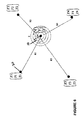
- FIG. 1 is a schematic diagram of a basic subsurface positioning system according to the invention utilizing radio frequencies that are medium penetrating radio transmissions.
- FIG. 2 is a schematic diagram of an Underground Positioning System (UPS) element suitable for the system of FIG. 1 .
- UPS Underground Positioning System
- FIG. 3A to 3C are schematic diagrams of the subterranean positioning system of FIG. 1 showing transmission from the radio frequency antennae to the UPS elements from various positions.
- FIG. 4 is a schematic diagram of the subterranean positioning system of FIG. 1 showing the relay of transmissions from the UPS elements to the base radio frequency antenna.
- FIG. 5 is a schematic diagram of a basic subterranean positioning system according to the invention utilizing a combination of radio frequencies that are medium penetrating radio and acoustic transmissions.
- FIG. 6 is a schematic diagram of a triangulation system using a probabilistic function for determining time of flight.
- FIG. 7 is a schematic diagram of an Underground Positioning System (UPS) element suitable for the system of FIG. 5 .
- UPS Underground Positioning System
- FIG. 8 is a schematic diagram of the subterranean positioning system of FIG. 5 showing initial movement of a UPS element.
- FIGS. 9A to 9E are schematic diagrams of the subterranean positioning system of FIG. 5 showing transmission from the radio frequency antennae to the UPS elements from various positions.
- FIGS. 10A to 10C are schematic diagrams of the subterranean positioning system of FIG. 5 showing transmission from the acoustic transmitters to the UPS elements from various positions.
- FIG. 11 is a schematic diagram of the subterranean positioning system of FIG. 5 showing transmission from the UPS elements to the radio frequency and acoustic antennae.
- FIG. 12 is a schematic diagram of a further embodiment of a UPS element without an atomic clock.
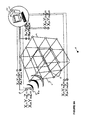
- FIG. 13 is a schematic diagram of a further embodiment of the subterranean positioning system showing an embodiment of the antennae with radio frequencies that are medium penetrating.
- FIGS. 14A to 14E are schematic diagrams of the subterranean positioning system of FIG. 13 showing transmission from the acoustic transmitters to the UPS elements from various positions.
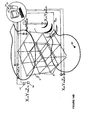
- FIG. 15 is a schematic diagram of the subterranean positioning system of FIG. 13 showing transmission from the UPS elements to the antennae with radio frequencies that are medium penetrating.
- FIG. 16 is a schematic diagram of a further embodiment of a UPS element without a microphone.
- the present invention provides a subsurface positioning system, one preferred embodiment of which is illustrated in FIG. 1 , and method, which is adaptable to virtually any subsurface environment or any fluid mass and is particularly suitable for use in block cave mining.
- the system and method of the invention will be described in the context of block cave mining, but it has applications in other environments and the description is not intended to be limiting in this regard.
- the system and method of the invention has application in most types of fluid materials, such as in mass movement in a fluid-plastic or viscous state, including mass creep, mass falls, mass slides, mass topples, or mass flows.
- This may include, by way of non-limiting example, movement of the soil, regolith, and rock by the force of gravity; mass movement resulting from slope failure, excavation or erosion; land slides; debris slides; debris flows; sand slides; sand flows; rock slides; rock flows; mud slides; mud flows; mud streams or lahars; soil, sediment or colluvium shifts, slides, or flows; riverbed movement; avalanches of snow, ice, rock or soil; ice flows; glacier flows; landfill, garbage, recycled goods or waste shifts or flows; human-made material flows; waste-water flow; or water flow.
- the system and method of the invention also has application as a positioning system for humans and assets in subsurface environments, which may include subterranean, submarine, or subglacial environments (both terrestrial and extra-terrestrial).
- the present invention provides a system for monitoring motion in a subsurface environment, comprising: at least first, second and third antennas for transmitting electromagnetic radiation (emr) signals from which time of flight data can be derived, each coupled to at least one signal transmitter, the first antenna for transmitting first antenna signals associated with the first antenna, the second antenna for transmitting second antenna signals associated with the second antenna, and the third antenna for transmitting third antenna signals associated with the third antenna; a plurality of underground positioning system (UPS) elements disposed in spaced relation within the subsurface environment, each UPS element comprising at least one UPS transmitter for transmitting an emr UPS signal comprising at least an identifier associating the UPS signal with the transmitting UPS element and data relating to signals received from the at least first, second and third antennas; and at least one UPS receiver for receiving the first antenna signals from the first antenna, the second antenna signals from the second antenna and the third antenna signals from the third antenna; and a base station antenna coupled to a base receiver and positioned for receiving the UPS signals and transmitting the UPS signals, or signals
- the present invention further provides a position monitoring system for monitoring motion in a subsurface environment, comprising: a plurality of underground positioning system (UPS) elements for suspending within the subsurface environment, each UPS element comprising at least a signal transmitter for transmitting a characteristic emr signal having an identifier for associating the signal with the transmitting UPS element; a first antenna coupled to a first signal receiver and positioned for receiving the characteristic signals from the UPS elements and transmitting the characteristic signals, or signals corresponding to the characteristic signals, to a data processing apparatus; and at least a second antenna coupled to the first signal receiver or another signal receiver and positioned for receiving the characteristic signals from the UPS elements and transmitting the characteristic signals.
- UPS underground positioning system
- the data processing apparatus receiving the signals from the first antenna and the at least second antenna corresponding to the characteristic signals from the UPS elements determines a location of each transmitting UPS element associated with each characteristic signal as at least one moving UPS elements moves, based on a time of flight defined by a transmit time at which each characteristic signal is transmitted and a receipt time at which each characteristic signal is received by the antennas thereby providing an indication of at least a direction or rate, or both, of the movement of the at least one moving UPS element.
- the present invention further provides, for use in a position monitoring system for monitoring motion in a subsurface environment comprising at least a first antenna coupled to a first signal receiver and positioned for receiving characteristic signals from the UPS elements and transmitting the characteristic signals to a data processing apparatus, an underground positioning system (UPS) element comprising at least: a housing, and a signal transmitter contained within the housing, for transmitting a characteristic emr signal having an identifier for associating the signal with the UPS element, whereby the data processing apparatus receiving the signals from the at least first antenna corresponding to the characteristic signals from the UPS elements determines a location of each UPS element associated with each characteristic signal as at least one moving UPS element moves, based on data from which time of flight data can be derived associated with each characteristic signal received by the at least first antenna, the characteristic signals transmitted by the UPS elements thereby providing an indication of at least a direction or rate, or both, of movement of the at least one moving UPS element.
- UPS underground positioning system
- the present invention further provides a method for monitoring motion in a subsurface environment, comprising the steps of: a. locating a plurality of underground positioning system (UPS) elements within the subsurface environment, each UPS element comprising at least a signal transmitter for transmitting a characteristic emr signal having an identifier for associating the characteristic signal with the transmitting UPS element; b. receiving the emr signals from the plurality of UPS elements at a first position in communication with the UPS elements, and transmitting data to a data processing apparatus corresponding to a time of receiving each emr signal at the first position; c.
- UPS underground positioning system
- time of flight data is derived at least in part from data provided to the antennas by an atomic clock.
- the at least one UPS transmitter is capable of retransmitting at least one UPS signal received from others of the plurality of UPS elements
- the UPS receiver is capable of receiving UPS signals from others of the plurality of UPS elements for retransmission
- the base antenna receives the UPS signals from at least one UPS element.
- each of the first, second and third antennas sequentially transmits a series of signal bursts
- time of flight data is derived at least in part from data identifying a phase shift between successive transmissions.
- at least some of the UPS elements comprise an acoustic receiver, and the system further comprises a plurality of acoustic transmitters for transmitting acoustic signals to the plurality of the UPS elements.
- Each of the UPS elements 10 is self-powered, for example by a lithium battery, and preferably capable of transmitting and/or receiving individual positional data on an ongoing basis for a number of years, which may for example be by means of IP protocol.
- transmission of positional information occurs using a radio frequency transmission capable of penetrating the medium, for example in the embodiment shown a Very Low Frequency (VLF) radio transmission system.
- VLF Very Low Frequency
- This system may be capable of data transmission through rock for distances of up to 2000 metres.
- other electromagnetic radiation (emr) transmission systems may be suitable depending upon the environment.
- Stratton, J. A., Electromagnetic Theory , McGraw-Hill (1941) provides a formula to calculate the electric and magnetic components of an electromagnetic wave in a medium as follows:
- the penetration depth is affected by conductivity (mineral content) and water content (% moisture). If the rock mass is highly conductive, the energy of transmission will dissipate within a few metres. In block caving operations, however, the ore is relatively low grade, from 0.4% to 1%. Lower frequencies allow for greater penetration, but the difficulty of the precise timing of the signals is exacerbated.
- FIG. 1 illustrates the basic positioning system used in the method of the invention, which relies on the principle of triangulation to localize a receiver to determine position using X, Y, Z coordinates.
- Each UPS element 10 broadcasts a coded emr signal, for example a VLF radio signal, including identifier information that can be discriminated by the base station computer 52 so the particular UPS element 10 from which the signal was sent is identifiable.
- the position of the UPS element 10 is localized as a point on a reference grid 4 , representing the monitored region 2 containing the group of UPS elements 10 .
- a group of UPS elements 10 is inserted into the rock mass.
- Each UPS element 10 illustrated schematically in FIG. 2 , is with at least a power source 11 and preferably positioning instrumentation.
- the UPS elements 10 of the preferred embodiment are equipped with a device that has both transmission and receiving capability (for example a VLF transceiver (not shown)), although the UPS elements 10 may alternatively be equipped with a device that has transmission capability (for example VLF transmitter 19 ) and a separate device that has receiving capability (for example VLF receiver 21 ).
- VLF transceiver not shown
- the casing may instead be configured irregularly to mimic the shape of a rock within the rock mass.
- An outer casing 12 houses an embedded computer 14 preferably with a triaxial gyroscope 13 , at least one triaxial accelerometer 15 and internal strain gauges 17 and possibly a triaxial inclinometer 23 .
- the strain gauges 17 while not part of the location system, can be useful for determining the forces acting on the UPS element 10 .
- UPS elements 10 To insert the UPS elements 10 into the rock mass within the monitored region 2 as shown in FIG. 1 , typically boreholes are drilled from the surface or a tunnel above the rock mass. These holes are approximately 6-inches in diameter and extend down into the rock to the required depth for the deepest UPS elements 10 .
- the UPS elements 10 are inserted and grouted into each borehole at a known elevation.
- the UPS elements 10 may be hung on a common power supply line (not shown) while in the borehole, to keep the batteries in the devices 10 fully charged until the rock mass begins to fail. These power lines prolong the battery power and thus the useful life of the UPS elements 10 . As the ore body begins to break, the power lines will disconnect from the UPS elements 10 and the UPS elements 10 will automatically switch to battery power.
- the initial system configuration for the preferred embodiment uses a reference grid 4 that represents the initial drilled locations of the UPS elements 10 within the monitored region 2 .
- the initial system configuration can be other than the grid pattern shown in FIG. 1 .
- insertion of the UPS elements 10 in a fan pattern (not shown) rather than a grid pattern may allow for insertion of the UPS elements 10 into the monitored region 2 from generally the same position on the surface, such that the drilling machinery does not need to be moved to different locations during the insertion process. Accessibility to certain areas on the surface may also be a factor influencing the initial system configuration for UPS element 10 insertion into the subsurface.
- Each UPS element 10 is embedded in a borehole and the initial location is logged in the 3D display software.
- the infrastructure consists of a base station computer 52 that manages VLF communication with the VLF antennas 20 .
- first, second and third antennas for respectively transmitting first, second and third antenna emr signals, for example as in the embodiment shown VLF antennas 20 .
- VLF antennas 20 There may be four or five VLF antennae 20 , or more, if desired, circumscribing the rock mass at different levels, as shown for example in the embodiment of FIG. 8 .
- Each VLF antenna is 20 disposed within communications range of both the current and expected prospective positions of the rock mass. Most of the VLF antennae 20 in this embodiment only need to be capable of signal transmission and not signal reception, except for the base station antenna 8 , which must be capable of signal reception as described below.
- the VLF antennae 20 are connected to an atomic clock station 24 , for example via coax connecting cables 22 , which contains or is connected to an atomic clock 26 .
- Each connecting cable 22 is of equal length for each VLF antennae 20 that is connected to the atomic clock station 24 , regardless of the distance of the VLF antennae 20 from the atomic clock station 24 , so that the VLF antennae 20 are operating in synchronous time.
- a first VLF antenna 20 transmits a first signal at time T 1 that contains time data from the atomic clock 26 and is received by an individual UPS element 10 and assigned coordinates X 1 Y 1 Z 1 based on that UPS element's position at the time the signal is received.
- T 1 thus corresponds to an initial position on a sine wave representing the time the first signal leaves the first VLF antenna 20 , as shown in FIG. 3A .
- the first VLF antenna 20 transmits a burst of a predetermined number of pulses each, in turn, precisely calibrated to transmit at specified time intervals, for example every 5 milliseconds.
- the UPS elements 10 to associate the pulses with the specific VLF antenna making the transmission, by the pulse count; for example, if the transmissions cycle between the VLF antennas 20 after each VLF antenna has emitted a specific number of pulses, say 10 pulses over 50 milliseconds, then it is known that after the first 10 pulses from the first VLF antenna 20 the signal is being transmitted from the second VLF antenna 20 , and after 10 more pulses the signal is being transmitted from the third VLF antenna 20 , etc.
- T 2 corresponds to a second position on the sine wave representing the time a second signal leaves a second VLF antenna 20 , as shown in FIG. 3B , which is received by the individual UPS element 10 and assigned coordinates X 2 Y 2 Z 2 based on the position of that UPS element 10 at the time the second signal (burst of pulses) is received.
- the second VLF antenna 20 thus transmits a second burst of pulses (which may commence immediately after the first VLF antenna 20 is finished sending the burst of pulses associated with the first VLF antenna 20 ) each, in turn, precisely calibrated to transmit at the specified time intervals, for example every 5 milliseconds.
- T 3 similarly corresponds to a third position on the sine wave representing the time a third signal leaves a third VLF antenna 20 , if present, as shown in FIG. 3C , which is received by the individual UPS element 10 and assigned coordinates X 3 Y 3 Z 3 based on the position of that UPS element 10 at the time the third signal is received.
- the third VLF antenna 20 transmits a third burst of pulses (which may commence immediately after the second VLF antenna 20 is finished sending the burst of pulses associated with the second VLF antenna 20 ) each, in turn, precisely calibrated to transmit at the specified time intervals, for example every 5 milliseconds.
- the UPS elements 10 are each capable of signal transmission and reception. Once a UPS element 10 receives the signals from the VLF antennae 20 , the UPS element 10 detects its position and then transmits a characteristic signal containing at least a unique identifier, and data representing the position of that UPS element 10 or time of flight. The characteristic signal from the transmitting UPS element 10 is received by all other UPS elements 10 within transmission range. The characteristic signals from other UPS elements 10 are similarly received and transmitted by UPS elements 10 within range to relay the data, in a cascading fashion, through the group of UPS elements 10 , until the signals from all (or substantially all) UPS elements 10 have been received by the base station antenna 8 .
- the base station antenna 8 is disposed within communications range of both the current and expected prospective positions of the rock mass, in the case of block cave mining preferably (but not necessarily) at the base of the rock mass. Because the UPS elements 10 in this embodiment not only transmit their own data but also serve as repeaters to transmit data received from other UPS elements 10 , the base station antenna 8 may be located anywhere within communication range of a single UPS element 10 in the current and expected positions of the rock mass.
- the base station antenna 8 receives from at least one of the UPS elements 10 , likely the UPS element or elements in closest proximity to the position of the base station antenna 8 , the relayed characteristic signals of all the UPS elements 10 containing positional data for each of the UPS elements 10 respectively associated with the unique identifier of each UPS element 10 .
- the relay of data by UPS elements 10 to the base station antenna 8 is shown in FIG. 4 .
- the characteristic signals from all of the UPS elements 10 are then transmitted from the base station antenna 8 back to the base station computer 52 , for example via coaxial cable.
- the base station computer 52 calculates any change in position of the UPS elements 10 based on the time of flight of the signals received by the UPS elements 10 from the VLF antennas 20 .
- time of flight can be derived from the phase differential between the multiple transmitted signals received and time-stamped by each UPS element 10 , which have subsequently been relayed through the UPS element matrix to the base station antenna 8 .
- the phase shift is proportional to the distance traveled by the signal, and can be calibrated to provide the (x, y, z) position in time for each UPS element 10 , for example as follows.
- the following describes a mathematical derivation of a phase measurement system that can be implemented in a digital measurement system using noisy signals.
- the averaging effect of the convolution process reduces the error in the final measurement.
- the following formulae are provided for an understanding of at least one manner in which data provided by the invention may be analyzed and utilized.
- the method of the invention relates to a system for generating positional data, and is not intended to be limited by how the data is processed or used.
- ⁇ wavelength (also equal to v/f; velocity/frequency)
- a receiver (and thus a UPS element 10 ) at position (x, y, z) can be considered within a volume.
- transmitters i.e. antennae 20
- A, B, C and D located at points (x A , y A , Z A ), (x B , y B , z B ), (x C , y C , z C ) and (X D , y D , Z D ) each transmitting a burst of sine waves each in turn, precisely calibrated to commence (for example) every 5 milliseconds.
- ⁇ A D A ⁇
- D A the distance from transmitter A to the receiver
- ⁇ the wavelength of the frequency of interest in the medium. Converting the phase shift to a distance is accomplished by the following:
- the signals can be stored in circuitry on board the UPS element 10 that can numerically determine the phase shift ⁇ for each signal. It may also be possible for all of this information to be transmitted back to the base station computer 52 for such calculations. Absolute phase cannot be measured at the receiver, only relative phase differences. The phase differences represent hyperbolic curves, and the intersection of the curves provides the (x, y, z) position of the receiver. Four transmitters are preferred to provide enough information for the three variables that will locate the receiver with the preferred degree of accuracy. The position of the receiver may be determined if only three transmitters are used, although the result will be less accurate.
- D ⁇ square root over (( x ⁇ x A ) 2 +( y ⁇ y A ) 2 +( z ⁇ z A ) 2 ) ⁇ square root over (( x ⁇ x A ) 2 +( y ⁇ y A ) 2 +( z ⁇ z A ) 2 ) ⁇ square root over (( x ⁇ x A ) 2 +( y ⁇ y A ) 2 +( z ⁇ z A ) 2 ) ⁇ square root over (( x ⁇ x A ) 2 +( y ⁇ y A ) 2 +( z ⁇ z A ) 2 ) ⁇
- D AB the difference between D A and D B as defined above.
- This system of equations can be solved to provide the x, y and z coordinates of the receiver, and thus of the transmitting UPS element 10 .
- Other systems may be used to calculate the positions of the UPS elements from their respective transmissions.
- the UPS elements 10 may also be affixed to humans (for example, miners) or assets—such as machinery, vehicles or automated devices—within a subsurface environment (including an underwater environment), and perform the same function.
- the person or asset (with the UPS element 10 attached) may be in a tunnel within a rock body or in a body of water.
- the attached UPS element 10 functions in a similar fashion as when entrained in the rock strata as described above.
- the position of the attached UPS element 10 provides information about the movement and position of the person or asset within the subsurface environment.
- the invention described herein may be used in any subsurface environment in which a radio frequency transmission is capable of penetrating the medium.
- the present invention has application in submarine environments where the UPS elements 10 may be used to determine the flow characteristics of the water, or for the position of humans (for example, divers) or assets at any given depth, for example on the bed of the water body, such as the ocean floor.
- the present invention also has application in other environments, such as in extra-terrestrial or nano-environments.
- the functionality of the present invention is not frequency dependent. The frequency can be selected to suit the particular environment in which the positioning system of the present invention is employed. In micro-environments a higher frequency may be used, whereas in a macro-environment a very low frequency may be used.
- each UPS element 10 is provided with its own atomic clock 18 and generates time data internally, from which time of flight to each VLF antenna 20 may be determined, for transmission to the base station antenna 8 .
- the UPS elements 10 transmit positional data, or data from which positional data may be derived such as time data, which is received by at least two VLF antennas 20 disposed within communications range of both the current and expected prospective positions of the rock mass, and preferably three, four or five VLF antennas 20 circumscribing the rock mass at different levels similar to those VLF antennas 20 shown in FIG. 5 .
- the VLF antennas 20 receive the signals from the UPS elements 10 and transmit the received signals to the base station 50 .
- UPS elements 10 capable of signal transmission and reception are preferred, but UPS elements 10 capable of signal transmission and not signal reception can also be used. All the antennas 20 may be coupled to signal transmitter (not shown), or each antenna may be coupled to its own signal transmitter, for transmitting the received signal to the base station 50 .
- the spatial path each UPS element 10 follows over time is determined. From this information, empirical information about the flow path, rate of flow, and the dynamic characteristics of the cave is calculated. The data may be plotted on a three-dimensional “Geographic Information System” or GIS.
- GIS Geographic Information System
- the position of the UPS element 10 may be determined by Equation E1:
- Equation E1 can be solved using several methods in order to reduce the positioning error of the UPS element 10 .
- the preferred method is to add the delays in the right side of the equations and simulate the solutions until the errors are reduced to a minimum value.
- a mathematical algorithm for positioning may be employed in order to correct for variation of signal characteristics due to travel within the rock mass.
- the first approach to the mathematical algorithm is reference to a specific type of signal, such as an acoustic signal.
- the correcting algorithm can then be extended to any kind of signal, since a general formula for any type of known signal can be modeled using the wave equation derived by the combination of three main properties in physics, namely the conservation of momentum, the conservation of mass, and the incompressible fluid equation.
- VLF antennas 20 receive positional signals from the UPS elements 10 in order to precisely determine the position of the rock in the cave, an estimate of the position of the rock is to solve the system of equations (E2) as follows:
- This method consists of keeping equation 1 and replacing the others by subtracting 1 from each of them.
- This leads to a system of the form AX+BX+CZ which is a linear system of equation that can easily be solved.
- FIG. 6 illustrates the situation where the time of flight of each signal is probabilistic. As more sources are added to the system, the zone of uncertainty shrinks, leading to a better approximation of the position. Equation (E1) can be transformed to include the uncertainty zone as follows:
- atomic clocks 18 are used in combination with acoustic cave front analysis.
- This embodiment combines acoustic and very low frequency (VLF) radio transmissions, and has the ability to provide very accurate and useful information about the cave front behaviour.
- VLF very low frequency
- FIG. 7 shows a UPS element suitable for this embodiment, with a microphone 16 for receiving acoustic signals and an atomic clock 18 .
- Waves that travel at the speed of light through rock will likely arrive more quickly than acoustic waves, because sound waves do not travel as quickly through rock as radio waves do. Generally, this difference is due to the presence of fractures in the rock. For example, when a radio signal and acoustic signal are sent simultaneously, once the radio wave (that traveled at the speed of light) and acoustic wave arrive at the UPS element 10 , the relative difference in arrival time is an indication of the quality of the rock through which the signals passed, i.e. the number and degree of fractures.
- the atomic clock 18 must have very high resolution due to the close distances between UPS elements 10 and the fact that VLF radio transmission takes place at the speed of light.
- Communication to and from the UPS elements 10 in this embodiment occurs via a VLF radio network using a plurality of VLF antennas 20 .
- the VLF antennas 20 are installed around the ore body in known locations (X 1V ,Y 1V ,Z 1V ), (X 2V ,Y 2V ,Z 2V ) and (X 3V ,Y 3V ,Z 3V ).
- the acoustic technology in this embodiment includes a combination of external acoustic transmitters or generators 30 for positioning and use of the VLF antennas 20 .
- the acoustic transmitters 30 are installed around the ore body in known locations (X 1A ,Y 1A ,Z 1A ), (X 2A ,Y 2A ,Z 2A ) and (X 3A ,Y 3A ,Z 3A ).
- each acoustic transmitter 30 is connected to the base station 50 .
- the UPS elements 10 , acoustic transmitters 30 , and VLF antennas 20 are positioned as described above.
- a motion detector inside each UPS element 10 is activated.
- Triaxial clinometers, accelerometers, and strain gauges collect the data from the UPS element 10 movement. This information provides data about the movement of the individual UPS element 10 , which is stored in the memory of the UPS element on-board computer 14 for transmission to the VLF antennas 20 and then via the VLF, antennae 20 network to the base station 50 , where the data is input into the mathematical equations for resolving.
- all atomic clocks must first be synchronized to ensure accuracy.
- FIG. 8 conceptually illustrates initial movement of an individual UPS element 10 , at the point of a VLF transmission from UPS element 10 to the VLF antennas 20 (as shown in FIG. 11 ), and from there to the base station 50 , to signal initial movement of the UPS element 10 .
- the base station computer 52 processes the VLF data received and commands each acoustic transmitter 30 to send a signal to the UPS elements 10 , as shown in FIGS.
- each VLF antenna 20 similarly commands each VLF antenna 20 to send a signal to the UPS elements 10 as shown in FIGS. 10A to 10C , measuring the duration of travel which will be at the speed of light.
- the UPS elements 10 it is not necessary for the UPS elements 10 to send a signal to indicate initial movement. Instead, the acoustic transmitters 30 send a signal at known intervals, which are received by the UPS elements 10 . Similarly, the VLF antennas 20 send a signal at known intervals, which are received by the UPS elements 10 .
- the base station 50 will preferably be sent two data sets.
- the data sets can be used to derive, among other information, the arrival time of the VLF radio waves and the arrival time of the acoustic waves at the UPS elements 10 .
- the VLF data will be more immediate while the acoustic will be slower, but may provide clues as to the rock characteristics from the on-board computer 14 in each UPS element 10 to compare and analyze.
- FIG. 11 shows the transmission of the VLF/atomic clock and the acoustic information data sets back to the base station 50 for determination of the mathematical solution.
- each UPS element 10 can be equipped with a repeater function, and able to receive and relay data sets from neighbouring UPS elements 10 .
- This relay Matrix can transmit the data sets from one UPS element 10 to another, either randomly or in the general direction of the base station 50 , essentially cascading data signals between UPS elements 10 , with the UPS element or elements that are closest to the base station 50 finally transmitting the data sets to the base station 50 directly (or a VLF receiver that can subsequently transmit the data sets to the base station).
- Such a relay matrix would require transmission of signals only over short distances (for example, less than 30 metres between UPS elements) allowing the UPS elements 10 to conserve power.
- each UPS element 10 transmits the data sets to a VLF antenna 20 to be relayed to the base station 50 . In yet another embodiment of the invention, each UPS element 10 transmits the data sets directly to the base station 50 .
- each transmission (whether acoustic or VLF radio) is preferably time-stamped with the instantaneous time setting of the atomic clock 18 of the transmitting component at the moment of transmission, and associated with the instantaneous time setting of the atomic clock 18 of the receiving component at the moment of reception.
- the base station computer 52 calculates, for each acoustic signal emitted by the various acoustic transmitters 30 , the time of flight (time elapsed between transmission from the acoustic transmitter 30 and reception by the UPS element 10 ); and for each VLF radio signal the time of flight (time elapsed between transmission of the signal from the various VLF antennas 20 and reception of the VLF radio signal by each UPS element 10 ).
- the monitoring system and method of the invention can be accomplished using only one type of transmission.
- the additional information provided by using two different transmission types, in the described embodiment for example acoustic and VLF radio transmissions, can significantly improve the accuracy of the data analysis.
- the VLF radio communication travels at much higher speed than the acoustic signals through the rock.
- the result of this is a higher degree of accuracy for the embodiment of the invention utilizing VLF radio as an atomic clock 18 is used for time stamping transmission and reception times.
- This is referred to as “tight data,” while the acoustic data is referred to as “loose data,” which does not require the same degree of precision time-stamping.
- tight data the acoustic data
- a larger error difference between duration of travel indicates that the rock is more fragmented and less competent.
- VLF radio frequency signal travel is much greater through the rock than acoustic signal travel and therefore a greater degree of error is expected from the acoustic signals.
- This larger error compared with the lower error of the VLF system, provides a richer sensing system. This in turn provides a more detailed view of the cave front.
- the result is a conceptual picture of what the caving front composition might look like at the time of analysis.
- the process is repeated at intervals, preferably daily or weekly for instance, for use in describing the behaviour of an ore body in this mining method.
- FIG. 12 illustrates a schematic of the UPS element 70 of this embodiment, which comprises a combination of external acoustic transmitters 30 for positioning and VLF antennas 20 for communication of time of flight information to the base station computer 52 for triangulation.
- the UPS elements 70 may have all the same internal components as the UPS elements 10 of the previously-described embodiment, except that an atomic clock is not required in the UPS elements 70 in this embodiment and instead the relative time of reception by the various VLF antennae (which can still provide timing information) and acoustic receivers is used for triangulation calculations to determine instantaneous positions of the UPS elements 70 .
- VLF antennas 20 it is possible to use either the VLF antennas 20 as in the preferred embodiment or a VLF loop antenna 40 , more preferably two VLF loop antennas 40 .
- the use of VLF loop antennas 40 provides for a large coverage area for VLF signal transmitting and receiving.
- FIG. 13 shows the initial setup of the VLF loop antennas 40 .
- One is located at the surface and one below monitored region.
- the antenna located below the monitored region may be positioned in mine tunnels, for example.
- VLF ferrite core antennae can be used instead of VLF loop antennas 40 .
- VLF loop antenna 40 is wrapped around a ferrite core, instead of as a continuous loop, this enables transmission of a VLF radio signal from a known point since each VLF ferrite core antenna can be placed in a Predetermined position.
- the UPS elements 70 are inserted in a drilling grid formation as in the embodiment described above.
- a motion detector (or triaxial gyro 13 ) 73 inside the UPS element 70 casing 72 is activated.
- Triaxial inclinometers 75 , accelerometers 76 , and strain gauges 77 collect the data from the movement and store it in the memory of the UPS element 70 on-board computer 74 for transmission via the VLF antennae 20 to the base station 50 for input into the mathematical equations for resolving.
- the motion detector 73 While the on-board sensing information is being collected, the motion detector 73 sends a signal to the on-board computer 74 indicating movement. A signal is then relayed via the VLF antennae 20 to the base station 50 .
- the base station computer 52 processes the VLF data received and commands each acoustic transmitter 30 to send the signal to each UPS element 70 to begin acoustic location of the UPS element 70 .
- the motion detector 73 and short term storage in the on-board computer 74 reduce the amount of time the computers and sensors are powered, allowing for a ‘sleep’ mode when the UPS element 70 is motionless for a selected time period, which in turn reduces power consumption and increases the length of time the UPS element 70 is available for data collection.
- FIG. 14A to 14E illustrate measurement of the duration of travel for each signal from the base station 50 to the UPS element 70 .
- FIG. 15 illustrates the UPS element 70 transmission times back to base station 50 for triangulation.
- a signal containing all data stored in each UPS element 70 is transmitted to the base station computer 52 for calculation, data analysis, and if desired, visual representation.
- This embodiment can utilize acoustic transmission technologies similar to those currently used for VLF voice communication and microseismic systems. The transmission capability is variable depending on the rock types and location resolution.
- FIG. 16 illustrates a schematic of the UPS element 80 of this embodiment.
- the UPS elements 80 of this embodiment As movement of the UPS elements 80 of this embodiment begins, motion detectors awaken the UPS element 80 and the system goes online.
- the triaxial clinometers and accelerometers collect the data from the rock movement.
- the UPS element 80 sends out a signal to the base station 50 that it has moved location.
- the base station computer 52 calculates the time elapsed for each signal to reach the UPS element 80 . Through triangulation, an accurate picture of UPS element 80 movement and location is obtained. The accuracy of path description and underground GPS system is a function of the number of VLF antennae 20 used. With each additional VLF antenna 20 , a better picture of actual movement is calculated.
- This concept has the advantage of being very accurate due to the transmission being at the speed of light combined with atomic clocks 18 . It is also robust and has improved survivability. The cost associated with developing the initial system is high, however, over the long term this system may be less costly.
- a further embodiment of the invention may use gyroscope-based UPS elements (not shown).
- the UPS elements do not need a microphone or atomic clock.
- Communication to and from the UPS elements 10 is via a VLF radio network with a large loop antenna, preferably two large loop antennas 40 .
- VLF ferrite core antennas are not necessary.
- the initial system configuration of the UPS elements 10 for this embodiment of the invention is similar to the first embodiment.
- the internal sensing system of the UPS element 10 begins to work.
- the accelerometers sense movement and the triaxial gyroscopes keep track of small displacements and rotations. This information provides individual UPS element x,y,z coordinate data. This information is stored in the on-board computer 14 ready for transmission via the VLF radio network.
- the UPS element 10 transmits its location to the loop antennas 40 and ultimately the base station 50 for display. Since each UPS element 10 has a VLF transmission system, on-board information, can be transmitted from the UPS element 10 to the VLF loop antennas 10 . This system is a one-way system to download data, which occurs at low speeds, specifically in the order of a few baud. A sequence of slow speed communications occurs to download the position data from the UPS elements 10 to the base station computer 52 for display. In this embodiment, the mathematical calculations discussed above are not necessary since the instrumentation is on-board each UPS element 10 , so the location is determined directly by the on-board sensing system.
- each UPS element 10 moves at once.
- each UPS element transmits its data at random times to reduce collisions and resulting information loss. This allows all the data to be transmitted slowly, which is necessary as VLF is a very low capacity system.
- VLF is a very low capacity system.
- the movement within the rock body is expected to be slow, so a slow rate of data transmission is not problematic.
Abstract
Description
where:
-
- α=attenuation constant in Nepers
- z=propagation distance in m
- ω=frequency in radians/s
- β=phase constant in radians/m
- μ=magnetic permeability
- σ=Conductivity in siemens/m
- δ=skin depth in meters=length at which wave attenuates to
-
- of its value
E(x,t)=E o e i(ωt-λx)
S=sin(ωt)
where DA is the distance from transmitter A to the receiver, and λ is the wavelength of the frequency of interest in the medium. Converting the phase shift to a distance is accomplished by the following:
S A=sin(ωt+θ A)
S B=sin(ωt+θ B)
S C=sin(ωt+θ C)
S D=sin(ωt+θ D)
D=√{square root over ((x−x A)2+(y−y A)2+(z−z A)2)}{square root over ((x−x A)2+(y−y A)2+(z−z A)2)}{square root over ((x−x A)2+(y−y A)2+(z−z A)2)}
D A −D B =D AB=√{square root over ((x−x A)2+(y−y A)2+(z−z A)2)}{square root over ((x−x A)2+(y−y A)2+(z−z A)2)}{square root over ((x−x A)2+(y−y A)2+(z−z A)2)}−√{square root over ((x−x B)2+(y−y B)2+(z−z B)2)}{square root over ((x−x B)2+(y−y B)2+(z−z B)2)}{square root over ((x−x B)2+(y−y B)2+(z−z B)2)}
D A −D C =D AC=√{square root over ((x−x A)2+(y−y A)2+(z−z A)2)}{square root over ((x−x A)2+(y−y A)2+(z−z A)2)}{square root over ((x−x A)2+(y−y A)2+(z−z A)2)}−√{square root over ((x−x C)2+(y−y C)2+(z−z C)2)}{square root over ((x−x C)2+(y−y C)2+(z−z C)2)}{square root over ((x−x C)2+(y−y C)2+(z−z C)2)}
D C −D B =D CB=√{square root over ((x−x C)2+(y−y C)2+(z−z C)2)}{square root over ((x−x C)2+(y−y C)2+(z−z C)2)}{square root over ((x−x C)2+(y−y C)2+(z−z C)2)}−√{square root over ((x−x B)2+(y−y B)2+(z−z B)2)}{square root over ((x−x B)2+(y−y B)2+(z−z B)2)}{square root over ((x−x B)2+(y−y B)2+(z−z B)2)}
D C −D D =D CD=√{square root over ((x−x C)2+(y−y C)2+(z−z C)2)}{square root over ((x−x C)2+(y−y C)2+(z−z C)2)}{square root over ((x−x C)2+(y−y C)2+(z−z C)2)}−√{square root over ((x−x D)2+(y−y D)2+(z−z D)2)}{square root over ((x−x D)2+(y−y D)2+(z−z D)2)}{square root over ((x−x D)2+(y−y D)2+(z−z D)2)}
D AB−√{square root over ((x−x A)2+(y−y A)2+(z−z A)2)}{square root over ((x−x A)2+(y−y A)2+(z−z A)2)}{square root over ((x−x A)2+(y−y A)2+(z−z A)2)}=√{square root over ((x−x B)2+(y−y B)2+(z−z B)2)}{square root over ((x−x B)2+(y−y B)2+(z−z B)2)}{square root over ((x−x B)2+(y−y B)2+(z−z B)2)}
D AC−√{square root over ((x−x A)2+(y−y A)2+(z−z A)2)}{square root over ((x−x A)2+(y−y A)2+(z−z A)2)}{square root over ((x−x A)2+(y−y A)2+(z−z A)2)}=√{square root over ((x−x C)2+(y−y C)2+(z−z C)2)}{square root over ((x−x C)2+(y−y C)2+(z−z C)2)}{square root over ((x−x C)2+(y−y C)2+(z−z C)2)}
D CB−√{square root over ((x−x C)2+(y−y C)2+(z−z C)2)}{square root over ((x−x C)2+(y−y C)2+(z−z C)2)}{square root over ((x−x C)2+(y−y C)2+(z−z C)2)}=√{square root over ((x−x B)2+(y−y B)2+(z−z B)2)}{square root over ((x−x B)2+(y−y B)2+(z−z B)2)}{square root over ((x−x B)2+(y−y B)2+(z−z B)2)}
D CD−√{square root over ((x−x C)2+(y−y C)2+(z−z C)2)}{square root over ((x−x C)2+(y−y C)2+(z−z C)2)}{square root over ((x−x C)2+(y−y C)2+(z−z C)2)}=√{square root over ((x−x D)2+(y−y D)2+(z−z D)2)}{square root over ((x−x D)2+(y−y D)2+(z−z D)2)}{square root over ((x−x D)2+(y−y D)2+(z−z D)2)}
√{square root over ((x−x A)2+(y−y A)2+(z−z A)2)}{square root over ((x−x A)2+(y−y A)2+(z−z A)2)}{square root over ((x−x A)2+(y−y A)2+(z−z A)2)}=[−D 2 AB+2xx A −x 2 A+2yy A −y 2 A+2zz A −z 2 A−2xx B +x 2 B−2yy B +y 2 B−2zz B +z 2 B]/(−2D AB)
√{square root over ((x−x A)2+(y−y A)2+(z−z A)2)}{square root over ((x−x A)2+(y−y A)2+(z−z A)2)}{square root over ((x−x A)2+(y−y A)2+(z−z A)2)}=[−D 2 AC+2xx A −x 2 A+2yy A −y 2 A+2zz A −z 2 A−2xx C +x 2 C−2yy C +y 2 C−2zz C +z 2 C]/(−2D AC)
√{square root over ((x−x C)2+(y−y C)2+(z−z C)2)}{square root over ((x−x C)2+(y−y C)2+(z−z C)2)}{square root over ((x−x C)2+(y−y C)2+(z−z C)2)}=[−D 2 CB+2xx C −x 2 C+2yy C −y 2 C+2zz C −z 2 C−2xx B +x 2 B−2yy B +y 2 B−2zz B +z 2 B]/(−2D CB)
√{square root over ((x−x C)2+(y−y C)2+(z−z C)2)}{square root over ((x−x C)2+(y−y C)2+(z−z C)2)}{square root over ((x−x C)2+(y−y C)2+(z−z C)2)}=[−D 2 CD+2xx C −x 2 C+2yy C −y 2 C+2zz C −z 2 C−2xx D +x 2 D−2yy D +y 2 D−2zz D +z 2 D]/(−2D CD)
Equation E1 can be solved using several methods in order to reduce the positioning error of the
Claims (24)
Applications Claiming Priority (4)
| Application Number | Priority Date | Filing Date | Title |
|---|---|---|---|
| CA002589820A CA2589820A1 (en) | 2007-05-24 | 2007-05-24 | Subterranean positioning system for monitoring movement underground and method |
| CA2,589,820 | 2007-05-24 | ||
| CA2589820 | 2007-05-24 | ||
| PCT/CA2008/001015 WO2008141465A1 (en) | 2007-05-24 | 2008-05-23 | Subsurface positioning system and method for monitoring movement underground |
Publications (2)
| Publication Number | Publication Date |
|---|---|
| US20110006774A1 US20110006774A1 (en) | 2011-01-13 |
| US8310238B2 true US8310238B2 (en) | 2012-11-13 |
Family
ID=40031375
Family Applications (1)
| Application Number | Title | Priority Date | Filing Date |
|---|---|---|---|
| US12/601,750 Active 2029-06-11 US8310238B2 (en) | 2007-05-24 | 2008-05-23 | Subsurface positioning system and method for monitoring movement underground |
Country Status (8)
| Country | Link |
|---|---|
| US (1) | US8310238B2 (en) |
| CN (1) | CN101802645B (en) |
| AU (1) | AU2008253522B2 (en) |
| BR (1) | BRPI0812168B1 (en) |
| CA (2) | CA2589820A1 (en) |
| RU (1) | RU2453862C2 (en) |
| WO (1) | WO2008141465A1 (en) |
| ZA (1) | ZA200908627B (en) |
Cited By (2)
| Publication number | Priority date | Publication date | Assignee | Title |
|---|---|---|---|---|
| US20150155637A1 (en) * | 2012-06-07 | 2015-06-04 | Mindspark Technologies Pty Ltd | Methods, systems and devices for monitoring movement of rock in a mine |
| US20150333843A1 (en) * | 2012-02-08 | 2015-11-19 | Vital Alert Communiation Inc. | System, method and apparatus for controlling buried devices |
Families Citing this family (46)
| Publication number | Priority date | Publication date | Assignee | Title |
|---|---|---|---|---|
| US10416276B2 (en) | 2010-11-12 | 2019-09-17 | Position Imaging, Inc. | Position tracking system and method using radio signals and inertial sensing |
| US11175375B2 (en) | 2010-11-12 | 2021-11-16 | Position Imaging, Inc. | Position tracking system and method using radio signals and inertial sensing |
| US9933509B2 (en) | 2011-11-10 | 2018-04-03 | Position Imaging, Inc. | System for tracking an object using pulsed frequency hopping |
| US9945940B2 (en) | 2011-11-10 | 2018-04-17 | Position Imaging, Inc. | Systems and methods of wireless position tracking |
| CN102495429B (en) * | 2011-12-01 | 2015-09-30 | 昆明理工大学 | A kind of ore deposit rock surface of contact tracing method |
| US9002675B2 (en) | 2012-02-23 | 2015-04-07 | Ultra Electronics Maritime Systems Inc. | Magneto-inductive positioning using a rotating magnetic field |
| AU2013225960A1 (en) * | 2012-02-28 | 2014-09-18 | Cidra Corporate Services Inc. | Acoustic monitoring of block caving |
| US10269182B2 (en) | 2012-06-14 | 2019-04-23 | Position Imaging, Inc. | RF tracking with active sensory feedback |
| US9782669B1 (en) | 2012-06-14 | 2017-10-10 | Position Imaging, Inc. | RF tracking with active sensory feedback |
| US9519344B1 (en) | 2012-08-14 | 2016-12-13 | Position Imaging, Inc. | User input system for immersive interaction |
| US10180490B1 (en) | 2012-08-24 | 2019-01-15 | Position Imaging, Inc. | Radio frequency communication system |
| AU2013332250B2 (en) | 2012-10-19 | 2017-06-29 | Orica International Pte Ltd | Locating underground markers |
| US10234539B2 (en) | 2012-12-15 | 2019-03-19 | Position Imaging, Inc. | Cycling reference multiplexing receiver system |
| US10856108B2 (en) | 2013-01-18 | 2020-12-01 | Position Imaging, Inc. | System and method of locating a radio frequency (RF) tracking device using a calibration routine |
| US9482741B1 (en) | 2013-01-18 | 2016-11-01 | Position Imaging, Inc. | System and method of locating a radio frequency (RF) tracking device using a calibration routine |
| CN103114846B (en) * | 2013-01-25 | 2016-05-25 | 北京航空航天大学 | A kind for the treatment of system afterwards of the deviational survey data based on optic fiber gyroscope inclinometer |
| US10634761B2 (en) | 2013-12-13 | 2020-04-28 | Position Imaging, Inc. | Tracking system with mobile reader |
| US9497728B2 (en) | 2014-01-17 | 2016-11-15 | Position Imaging, Inc. | Wireless relay station for radio frequency-based tracking system |
| US10200819B2 (en) | 2014-02-06 | 2019-02-05 | Position Imaging, Inc. | Virtual reality and augmented reality functionality for mobile devices |
| US10642560B2 (en) | 2015-02-13 | 2020-05-05 | Position Imaging, Inc. | Accurate geographic tracking of mobile devices |
| US10324474B2 (en) | 2015-02-13 | 2019-06-18 | Position Imaging, Inc. | Spatial diversity for relative position tracking |
| US11132004B2 (en) | 2015-02-13 | 2021-09-28 | Position Imaging, Inc. | Spatial diveristy for relative position tracking |
| US10853757B1 (en) | 2015-04-06 | 2020-12-01 | Position Imaging, Inc. | Video for real-time confirmation in package tracking systems |
| US11416805B1 (en) | 2015-04-06 | 2022-08-16 | Position Imaging, Inc. | Light-based guidance for package tracking systems |
| US11501244B1 (en) | 2015-04-06 | 2022-11-15 | Position Imaging, Inc. | Package tracking systems and methods |
| US10148918B1 (en) | 2015-04-06 | 2018-12-04 | Position Imaging, Inc. | Modular shelving systems for package tracking |
| US10445443B2 (en) * | 2015-09-28 | 2019-10-15 | Freeport-Mcmoran Inc. | Ground support design tool |
| US10444323B2 (en) | 2016-03-08 | 2019-10-15 | Position Imaging, Inc. | Expandable, decentralized position tracking systems and methods |
| CN106066178A (en) * | 2016-06-15 | 2016-11-02 | 中国地质调查局水文地质环境地质调查中心 | A kind of ice movement monitoring method and system |
| US11436553B2 (en) | 2016-09-08 | 2022-09-06 | Position Imaging, Inc. | System and method of object tracking using weight confirmation |
| CN106644732B (en) * | 2016-10-14 | 2023-12-05 | 宋世元 | Roof collapse monitoring test system |
| US10634503B2 (en) | 2016-12-12 | 2020-04-28 | Position Imaging, Inc. | System and method of personalized navigation inside a business enterprise |
| US10455364B2 (en) | 2016-12-12 | 2019-10-22 | Position Imaging, Inc. | System and method of personalized navigation inside a business enterprise |
| US10634506B2 (en) | 2016-12-12 | 2020-04-28 | Position Imaging, Inc. | System and method of personalized navigation inside a business enterprise |
| US11120392B2 (en) | 2017-01-06 | 2021-09-14 | Position Imaging, Inc. | System and method of calibrating a directional light source relative to a camera's field of view |
| CN108734847B (en) * | 2018-01-22 | 2020-02-07 | 华南农业大学 | Paper money thickness measuring method and device based on three-axis acceleration sensor |
| AU2019202048B2 (en) | 2018-03-26 | 2024-03-28 | Orica International Pte Ltd | 3D block modelling of a resource boundary in a post-blast muckpile to optimize destination delineation |
| WO2020061276A1 (en) | 2018-09-21 | 2020-03-26 | Position Imaging, Inc. | Machine-learning-assisted self-improving object-identification system and method |
| SE543288C2 (en) * | 2018-10-26 | 2020-11-17 | Mic Nordic Ab | Mining and mineral exploration system and method for performing time-accurate measurements in a mine |
| US11089232B2 (en) | 2019-01-11 | 2021-08-10 | Position Imaging, Inc. | Computer-vision-based object tracking and guidance module |
| CN110672087B (en) * | 2019-09-02 | 2023-08-11 | 湖南凌傲科技有限公司 | Human body tracking method and system |
| CN111123368B (en) * | 2019-12-31 | 2021-03-12 | 西安交通大学 | Detection device based on underwater low-frequency electric field and underwater detection positioning method |
| US11125084B1 (en) * | 2020-03-19 | 2021-09-21 | Newcrest Mining Limited | Mining method |
| RU2740514C9 (en) * | 2020-05-26 | 2021-05-17 | Открытое акционерное общество "Авангард" | Method for monitoring the state of underground structures of the subway and system for its implementation |
| CN114353782B (en) * | 2022-01-11 | 2023-06-20 | 华北理工大学 | Baseline-RFMDR-based underground positioning method and underground positioning device |
| CN117473908A (en) * | 2023-12-27 | 2024-01-30 | 中国科学院、水利部成都山地灾害与环境研究所 | Rock ice avalanche motion simulation method based on depth average quasi-multiphase model |
Citations (11)
| Publication number | Priority date | Publication date | Assignee | Title |
|---|---|---|---|---|
| US4742357A (en) | 1986-09-17 | 1988-05-03 | Rackley Ernie C | Stolen object location system |
| US4800391A (en) | 1987-11-03 | 1989-01-24 | Megapulse, Inc. | Method of and apparatus for message communication on Loran-C navigational signal broadcasts and the like with reduced navigation errors |
| US5155442A (en) * | 1991-03-01 | 1992-10-13 | John Mercer | Position and orientation locator/monitor |
| US5585726A (en) * | 1995-05-26 | 1996-12-17 | Utilx Corporation | Electronic guidance system and method for locating a discrete in-ground boring device |
| US6454023B1 (en) | 1997-04-16 | 2002-09-24 | Digital Control Incorporated | Mapping tool for tracking and/or guiding an underground boring tool |
| US6552548B1 (en) | 1998-06-15 | 2003-04-22 | Radiodetection Limited | Detecting underground objects |
| US6813324B1 (en) | 1999-08-05 | 2004-11-02 | Mine Radio Systems Inc. | Synchronized communication system |
| US20050077085A1 (en) | 2003-10-14 | 2005-04-14 | Rudolf Zeller | Tracking positions of personnel, vehicles, and inanimate objects |
| CA2633529A1 (en) | 2005-12-16 | 2007-07-05 | Raytheon Utd Inc. | Positioning system and method |
| WO2008049171A1 (en) | 2006-10-26 | 2008-05-02 | Cmte Development Limited | Flow tracking in block caving mining |
| US20090146864A1 (en) | 2005-05-27 | 2009-06-11 | Zank Paul A | Loran-based underground geolocation, navigation and communication system |
Family Cites Families (5)
| Publication number | Priority date | Publication date | Assignee | Title |
|---|---|---|---|---|
| GB9519087D0 (en) * | 1995-09-19 | 1995-11-22 | Cursor Positioning Sys Ltd | Navigation and tracking system |
| RU2100825C1 (en) * | 1996-05-23 | 1997-12-27 | Акционерное общество открытого типа Промышленно-инвестиционная компания "Прогресс" | Device for underground radar sounding |
| ATE337782T1 (en) * | 2000-08-17 | 2006-09-15 | Merck & Co Inc | CYCLOPENTYL MODULATORS OF CHEMOKINE RECEPTOR ACTIVITY |
| RU2244944C2 (en) * | 2002-10-01 | 2005-01-20 | ЗАО НПФ "Геофизическое дистанционное зондирование" | Method of identifying subsurface structures and local objects disposed in these structures |
| RU2283519C1 (en) * | 2005-05-18 | 2006-09-10 | Общество с ограниченной ответственностью "Межрегиональный центр по обеспечению пожаро- и взрывоопасности жилых и общественных зданий от горючих газов" | Geophysical complex gfk-1 for searching subsurface objects |
-
2007
- 2007-05-24 CA CA002589820A patent/CA2589820A1/en not_active Abandoned
-
2008
- 2008-05-23 BR BRPI0812168-0A patent/BRPI0812168B1/en not_active IP Right Cessation
- 2008-05-23 US US12/601,750 patent/US8310238B2/en active Active
- 2008-05-23 CN CN2008800252217A patent/CN101802645B/en active Active
- 2008-05-23 AU AU2008253522A patent/AU2008253522B2/en not_active Ceased
- 2008-05-23 CA CA2688006A patent/CA2688006C/en active Active
- 2008-05-23 WO PCT/CA2008/001015 patent/WO2008141465A1/en active Application Filing
- 2008-05-23 RU RU2009147804/07A patent/RU2453862C2/en active
-
2009
- 2009-12-04 ZA ZA2009/08627A patent/ZA200908627B/en unknown
Patent Citations (11)
| Publication number | Priority date | Publication date | Assignee | Title |
|---|---|---|---|---|
| US4742357A (en) | 1986-09-17 | 1988-05-03 | Rackley Ernie C | Stolen object location system |
| US4800391A (en) | 1987-11-03 | 1989-01-24 | Megapulse, Inc. | Method of and apparatus for message communication on Loran-C navigational signal broadcasts and the like with reduced navigation errors |
| US5155442A (en) * | 1991-03-01 | 1992-10-13 | John Mercer | Position and orientation locator/monitor |
| US5585726A (en) * | 1995-05-26 | 1996-12-17 | Utilx Corporation | Electronic guidance system and method for locating a discrete in-ground boring device |
| US6454023B1 (en) | 1997-04-16 | 2002-09-24 | Digital Control Incorporated | Mapping tool for tracking and/or guiding an underground boring tool |
| US6552548B1 (en) | 1998-06-15 | 2003-04-22 | Radiodetection Limited | Detecting underground objects |
| US6813324B1 (en) | 1999-08-05 | 2004-11-02 | Mine Radio Systems Inc. | Synchronized communication system |
| US20050077085A1 (en) | 2003-10-14 | 2005-04-14 | Rudolf Zeller | Tracking positions of personnel, vehicles, and inanimate objects |
| US20090146864A1 (en) | 2005-05-27 | 2009-06-11 | Zank Paul A | Loran-based underground geolocation, navigation and communication system |
| CA2633529A1 (en) | 2005-12-16 | 2007-07-05 | Raytheon Utd Inc. | Positioning system and method |
| WO2008049171A1 (en) | 2006-10-26 | 2008-05-02 | Cmte Development Limited | Flow tracking in block caving mining |
Cited By (4)
| Publication number | Priority date | Publication date | Assignee | Title |
|---|---|---|---|---|
| US20150333843A1 (en) * | 2012-02-08 | 2015-11-19 | Vital Alert Communiation Inc. | System, method and apparatus for controlling buried devices |
| US9450684B2 (en) * | 2012-02-08 | 2016-09-20 | Vital Alert Communication Inc. | System, method and apparatus for controlling buried devices |
| US20150155637A1 (en) * | 2012-06-07 | 2015-06-04 | Mindspark Technologies Pty Ltd | Methods, systems and devices for monitoring movement of rock in a mine |
| US10559892B2 (en) | 2012-06-07 | 2020-02-11 | Mindspark Technologies Pty Ltd | Methods, systems and devices for monitoring movement of rock in a mine |
Also Published As
| Publication number | Publication date |
|---|---|
| AU2008253522A1 (en) | 2008-11-27 |
| AU2008253522B2 (en) | 2012-03-15 |
| BRPI0812168A2 (en) | 2015-07-07 |
| ZA200908627B (en) | 2011-11-30 |
| BRPI0812168B1 (en) | 2021-04-27 |
| WO2008141465A1 (en) | 2008-11-27 |
| CA2589820A1 (en) | 2008-11-24 |
| CA2688006A1 (en) | 2008-11-27 |
| RU2453862C2 (en) | 2012-06-20 |
| RU2009147804A (en) | 2011-06-27 |
| CN101802645B (en) | 2013-07-17 |
| CA2688006C (en) | 2015-09-01 |
| CN101802645A (en) | 2010-08-11 |
| US20110006774A1 (en) | 2011-01-13 |
Similar Documents
| Publication | Publication Date | Title |
|---|---|---|
| US8310238B2 (en) | Subsurface positioning system and method for monitoring movement underground | |
| Feng et al. | Sectional velocity model for microseismic source location in tunnels | |
| US10539956B2 (en) | Subsurface robotic mapping system and method | |
| EP2895876B1 (en) | Locating underground markers | |
| US8991260B2 (en) | Pseudo rock and analysis system using the same | |
| CN110703320A (en) | Up-down combined microseismic monitoring system and method | |
| CN112965136B (en) | Multi-means advanced detection method for water-rich karst tunnel | |
| CN101100940B (en) | Arrayed sound signal detection system and its engineering uses | |
| CN101482621A (en) | Method for monitoring acceleration of sliding posture of sliding body | |
| CN103389527A (en) | Method and system for forecasting tunnel geology | |
| US20240102782A1 (en) | Method for Evaluating Deep-Buried Tunnel Blasting Parameters | |
| US20210109248A1 (en) | System, method, and device for real-time sinkhole detection | |
| CN103389524B (en) | The forecasting procedure of tunnel geology and system | |
| CN112505746A (en) | Detection system based on tunnel drilling and blasting construction and corresponding method thereof | |
| CN114776379A (en) | Mine earthquake comprehensive monitoring system and method for estimating mine earthquake damage range | |
| Zhou et al. | Automatic Acquisition System for Mine Pressure Monitoring in Coal Mine Working-Face Footage | |
| CN217080567U (en) | Mine earthquake comprehensive monitoring system | |
| Hakes et al. | NANOSEISMIC MONITORING FOR DETECTION OF ROCKFALLS: EXPERIMENTS IN QUARRY AREAS. | |
| CN219953448U (en) | Microseismic signal three-dimensional monitoring and early warning system for coal mine | |
| CN113740899A (en) | Coal mine stope seismic source monitoring and positioning system based on wireless transmission | |
| JP2012137413A (en) | Geological exploration system | |
| Meng et al. | The slope monitoring method research | |
| Cao et al. | Large-scale salt cavern collapse: Multi-parameter monitoring from precursor signs to general failure | |
| JP5845330B1 (en) | Geological exploration method | |
| CN117631078A (en) | Comprehensive monitoring system and method applied to coal mine gas control |
Legal Events
| Date | Code | Title | Description |
|---|---|---|---|
| AS | Assignment |
Owner name: PENGUIN AUTOMATED SYSTEMS, INC, CANADA Free format text: ASSIGNMENT OF ASSIGNORS INTEREST;ASSIGNOR:BAIDEN, GREG;REEL/FRAME:023566/0463 Effective date: 20070613 |
|
| STCF | Information on status: patent grant |
Free format text: PATENTED CASE |
|
| FPAY | Fee payment |
Year of fee payment: 4 |
|
| FEPP | Fee payment procedure |
Free format text: MAINTENANCE FEE REMINDER MAILED (ORIGINAL EVENT CODE: REM.); ENTITY STATUS OF PATENT OWNER: LARGE ENTITY |
|
| FEPP | Fee payment procedure |
Free format text: 7.5 YR SURCHARGE - LATE PMT W/IN 6 MO, LARGE ENTITY (ORIGINAL EVENT CODE: M1555); ENTITY STATUS OF PATENT OWNER: LARGE ENTITY |
|
| MAFP | Maintenance fee payment |
Free format text: PAYMENT OF MAINTENANCE FEE, 8TH YEAR, LARGE ENTITY (ORIGINAL EVENT CODE: M1552); ENTITY STATUS OF PATENT OWNER: LARGE ENTITY Year of fee payment: 8 |