US8323555B2 - System and method for forming a container having a grip region - Google Patents
System and method for forming a container having a grip region Download PDFInfo
- Publication number
- US8323555B2 US8323555B2 US12/856,484 US85648410A US8323555B2 US 8323555 B2 US8323555 B2 US 8323555B2 US 85648410 A US85648410 A US 85648410A US 8323555 B2 US8323555 B2 US 8323555B2
- Authority
- US
- United States
- Prior art keywords
- container
- base
- mold
- movable insert
- base forming
- Prior art date
- Legal status (The legal status is an assumption and is not a legal conclusion. Google has not performed a legal analysis and makes no representation as to the accuracy of the status listed.)
- Active, expires
Links
Images


Classifications
-
- B—PERFORMING OPERATIONS; TRANSPORTING
- B29—WORKING OF PLASTICS; WORKING OF SUBSTANCES IN A PLASTIC STATE IN GENERAL
- B29C—SHAPING OR JOINING OF PLASTICS; SHAPING OF MATERIAL IN A PLASTIC STATE, NOT OTHERWISE PROVIDED FOR; AFTER-TREATMENT OF THE SHAPED PRODUCTS, e.g. REPAIRING
- B29C49/00—Blow-moulding, i.e. blowing a preform or parison to a desired shape within a mould; Apparatus therefor
- B29C49/42—Component parts, details or accessories; Auxiliary operations
- B29C49/48—Moulds
- B29C49/4802—Moulds with means for locally compressing part(s) of the parison in the main blowing cavity
-
- B—PERFORMING OPERATIONS; TRANSPORTING
- B29—WORKING OF PLASTICS; WORKING OF SUBSTANCES IN A PLASTIC STATE IN GENERAL
- B29C—SHAPING OR JOINING OF PLASTICS; SHAPING OF MATERIAL IN A PLASTIC STATE, NOT OTHERWISE PROVIDED FOR; AFTER-TREATMENT OF THE SHAPED PRODUCTS, e.g. REPAIRING
- B29C49/00—Blow-moulding, i.e. blowing a preform or parison to a desired shape within a mould; Apparatus therefor
- B29C49/42—Component parts, details or accessories; Auxiliary operations
- B29C49/48—Moulds
- B29C49/54—Moulds for undercut articles
-
- B—PERFORMING OPERATIONS; TRANSPORTING
- B65—CONVEYING; PACKING; STORING; HANDLING THIN OR FILAMENTARY MATERIAL
- B65D—CONTAINERS FOR STORAGE OR TRANSPORT OF ARTICLES OR MATERIALS, e.g. BAGS, BARRELS, BOTTLES, BOXES, CANS, CARTONS, CRATES, DRUMS, JARS, TANKS, HOPPERS, FORWARDING CONTAINERS; ACCESSORIES, CLOSURES, OR FITTINGS THEREFOR; PACKAGING ELEMENTS; PACKAGES
- B65D23/00—Details of bottles or jars not otherwise provided for
- B65D23/10—Handles
- B65D23/102—Gripping means formed in the walls, e.g. roughening, cavities, projections
-
- B—PERFORMING OPERATIONS; TRANSPORTING
- B29—WORKING OF PLASTICS; WORKING OF SUBSTANCES IN A PLASTIC STATE IN GENERAL
- B29C—SHAPING OR JOINING OF PLASTICS; SHAPING OF MATERIAL IN A PLASTIC STATE, NOT OTHERWISE PROVIDED FOR; AFTER-TREATMENT OF THE SHAPED PRODUCTS, e.g. REPAIRING
- B29C2949/00—Indexing scheme relating to blow-moulding
- B29C2949/07—Preforms or parisons characterised by their configuration
- B29C2949/0715—Preforms or parisons characterised by their configuration the preform having one end closed
-
- B—PERFORMING OPERATIONS; TRANSPORTING
- B29—WORKING OF PLASTICS; WORKING OF SUBSTANCES IN A PLASTIC STATE IN GENERAL
- B29C—SHAPING OR JOINING OF PLASTICS; SHAPING OF MATERIAL IN A PLASTIC STATE, NOT OTHERWISE PROVIDED FOR; AFTER-TREATMENT OF THE SHAPED PRODUCTS, e.g. REPAIRING
- B29C2949/00—Indexing scheme relating to blow-moulding
- B29C2949/20—Preforms or parisons whereby a specific part is made of only one component, e.g. only one layer
- B29C2949/22—Preforms or parisons whereby a specific part is made of only one component, e.g. only one layer at neck portion
-
- B—PERFORMING OPERATIONS; TRANSPORTING
- B29—WORKING OF PLASTICS; WORKING OF SUBSTANCES IN A PLASTIC STATE IN GENERAL
- B29C—SHAPING OR JOINING OF PLASTICS; SHAPING OF MATERIAL IN A PLASTIC STATE, NOT OTHERWISE PROVIDED FOR; AFTER-TREATMENT OF THE SHAPED PRODUCTS, e.g. REPAIRING
- B29C2949/00—Indexing scheme relating to blow-moulding
- B29C2949/20—Preforms or parisons whereby a specific part is made of only one component, e.g. only one layer
- B29C2949/24—Preforms or parisons whereby a specific part is made of only one component, e.g. only one layer at flange portion
-
- B—PERFORMING OPERATIONS; TRANSPORTING
- B29—WORKING OF PLASTICS; WORKING OF SUBSTANCES IN A PLASTIC STATE IN GENERAL
- B29C—SHAPING OR JOINING OF PLASTICS; SHAPING OF MATERIAL IN A PLASTIC STATE, NOT OTHERWISE PROVIDED FOR; AFTER-TREATMENT OF THE SHAPED PRODUCTS, e.g. REPAIRING
- B29C2949/00—Indexing scheme relating to blow-moulding
- B29C2949/20—Preforms or parisons whereby a specific part is made of only one component, e.g. only one layer
- B29C2949/26—Preforms or parisons whereby a specific part is made of only one component, e.g. only one layer at body portion
-
- B—PERFORMING OPERATIONS; TRANSPORTING
- B29—WORKING OF PLASTICS; WORKING OF SUBSTANCES IN A PLASTIC STATE IN GENERAL
- B29C—SHAPING OR JOINING OF PLASTICS; SHAPING OF MATERIAL IN A PLASTIC STATE, NOT OTHERWISE PROVIDED FOR; AFTER-TREATMENT OF THE SHAPED PRODUCTS, e.g. REPAIRING
- B29C2949/00—Indexing scheme relating to blow-moulding
- B29C2949/20—Preforms or parisons whereby a specific part is made of only one component, e.g. only one layer
- B29C2949/28—Preforms or parisons whereby a specific part is made of only one component, e.g. only one layer at bottom portion
-
- B—PERFORMING OPERATIONS; TRANSPORTING
- B29—WORKING OF PLASTICS; WORKING OF SUBSTANCES IN A PLASTIC STATE IN GENERAL
- B29C—SHAPING OR JOINING OF PLASTICS; SHAPING OF MATERIAL IN A PLASTIC STATE, NOT OTHERWISE PROVIDED FOR; AFTER-TREATMENT OF THE SHAPED PRODUCTS, e.g. REPAIRING
- B29C49/00—Blow-moulding, i.e. blowing a preform or parison to a desired shape within a mould; Apparatus therefor
- B29C49/02—Combined blow-moulding and manufacture of the preform or the parison
- B29C49/06—Injection blow-moulding
-
- B—PERFORMING OPERATIONS; TRANSPORTING
- B29—WORKING OF PLASTICS; WORKING OF SUBSTANCES IN A PLASTIC STATE IN GENERAL
- B29C—SHAPING OR JOINING OF PLASTICS; SHAPING OF MATERIAL IN A PLASTIC STATE, NOT OTHERWISE PROVIDED FOR; AFTER-TREATMENT OF THE SHAPED PRODUCTS, e.g. REPAIRING
- B29C49/00—Blow-moulding, i.e. blowing a preform or parison to a desired shape within a mould; Apparatus therefor
- B29C49/22—Blow-moulding, i.e. blowing a preform or parison to a desired shape within a mould; Apparatus therefor using multilayered preforms or parisons
-
- B—PERFORMING OPERATIONS; TRANSPORTING
- B29—WORKING OF PLASTICS; WORKING OF SUBSTANCES IN A PLASTIC STATE IN GENERAL
- B29K—INDEXING SCHEME ASSOCIATED WITH SUBCLASSES B29B, B29C OR B29D, RELATING TO MOULDING MATERIALS OR TO MATERIALS FOR MOULDS, REINFORCEMENTS, FILLERS OR PREFORMED PARTS, e.g. INSERTS
- B29K2023/00—Use of polyalkenes or derivatives thereof as moulding material
- B29K2023/04—Polymers of ethylene
- B29K2023/06—PE, i.e. polyethylene
- B29K2023/0608—PE, i.e. polyethylene characterised by its density
- B29K2023/0633—LDPE, i.e. low density polyethylene
-
- B—PERFORMING OPERATIONS; TRANSPORTING
- B29—WORKING OF PLASTICS; WORKING OF SUBSTANCES IN A PLASTIC STATE IN GENERAL
- B29K—INDEXING SCHEME ASSOCIATED WITH SUBCLASSES B29B, B29C OR B29D, RELATING TO MOULDING MATERIALS OR TO MATERIALS FOR MOULDS, REINFORCEMENTS, FILLERS OR PREFORMED PARTS, e.g. INSERTS
- B29K2023/00—Use of polyalkenes or derivatives thereof as moulding material
- B29K2023/04—Polymers of ethylene
- B29K2023/06—PE, i.e. polyethylene
- B29K2023/0608—PE, i.e. polyethylene characterised by its density
- B29K2023/065—HDPE, i.e. high density polyethylene
-
- B—PERFORMING OPERATIONS; TRANSPORTING
- B29—WORKING OF PLASTICS; WORKING OF SUBSTANCES IN A PLASTIC STATE IN GENERAL
- B29K—INDEXING SCHEME ASSOCIATED WITH SUBCLASSES B29B, B29C OR B29D, RELATING TO MOULDING MATERIALS OR TO MATERIALS FOR MOULDS, REINFORCEMENTS, FILLERS OR PREFORMED PARTS, e.g. INSERTS
- B29K2023/00—Use of polyalkenes or derivatives thereof as moulding material
- B29K2023/04—Polymers of ethylene
- B29K2023/08—Copolymers of ethylene
- B29K2023/086—EVOH, i.e. ethylene vinyl alcohol copolymer
-
- B—PERFORMING OPERATIONS; TRANSPORTING
- B29—WORKING OF PLASTICS; WORKING OF SUBSTANCES IN A PLASTIC STATE IN GENERAL
- B29K—INDEXING SCHEME ASSOCIATED WITH SUBCLASSES B29B, B29C OR B29D, RELATING TO MOULDING MATERIALS OR TO MATERIALS FOR MOULDS, REINFORCEMENTS, FILLERS OR PREFORMED PARTS, e.g. INSERTS
- B29K2067/00—Use of polyesters or derivatives thereof, as moulding material
-
- B—PERFORMING OPERATIONS; TRANSPORTING
- B29—WORKING OF PLASTICS; WORKING OF SUBSTANCES IN A PLASTIC STATE IN GENERAL
- B29K—INDEXING SCHEME ASSOCIATED WITH SUBCLASSES B29B, B29C OR B29D, RELATING TO MOULDING MATERIALS OR TO MATERIALS FOR MOULDS, REINFORCEMENTS, FILLERS OR PREFORMED PARTS, e.g. INSERTS
- B29K2077/00—Use of PA, i.e. polyamides, e.g. polyesteramides or derivatives thereof, as moulding material
-
- B—PERFORMING OPERATIONS; TRANSPORTING
- B29—WORKING OF PLASTICS; WORKING OF SUBSTANCES IN A PLASTIC STATE IN GENERAL
- B29L—INDEXING SCHEME ASSOCIATED WITH SUBCLASS B29C, RELATING TO PARTICULAR ARTICLES
- B29L2031/00—Other particular articles
- B29L2031/46—Knobs or handles, push-buttons, grips
- B29L2031/463—Grips, handles
-
- B—PERFORMING OPERATIONS; TRANSPORTING
- B29—WORKING OF PLASTICS; WORKING OF SUBSTANCES IN A PLASTIC STATE IN GENERAL
- B29L—INDEXING SCHEME ASSOCIATED WITH SUBCLASS B29C, RELATING TO PARTICULAR ARTICLES
- B29L2031/00—Other particular articles
- B29L2031/712—Containers; Packaging elements or accessories, Packages
- B29L2031/7158—Bottles
Definitions
- the invention generally relates to a method for blow molding a container, and more particularly to a method for blow molding a container to be formed with deep-set grips so that the formed container has secure grippability along with a good ergonomic feel.
- the present invention also relates generally to forming a blow molded container, and more particularly to a method for forming a blow molded container that increases orientation of material at a region of the blow molded container.
- a preformed parison is prepared from a thermoplastic material, typically by an injection molding process.
- the preform typically includes a threaded end, which becomes the threads of the container.
- stretch blow molding the preform is positioned between two open blow mold halves.
- the blow mold halves close about the preform and cooperate to provide a cavity into which the preform is blown to form the container.
- a gas is forced into the perform causing it to stretch and to take the shape of the mold as the plastic contacts the mold.
- the mold halves open to release the blow molded container.
- a deep protrusion may be required to form a particular section of a container.
- the particular sections of the container formed by an inset or deep protrusion may include the dome, sidewalls, and the base of the container.
- the plastic As the plastic contacts the deep protrusion of the mold, the plastic must stretch and flow around the protrusion into a recess.
- the plastic material is less able to flow and stretch around the protrusion because, of the contact friction with the mold surface. Insufficient material distribution at a region, such as at the base, may affect the ability of the region to maintain its shape around the protrusion during hot filling, the strength of the region, or the ability of the container to stand on a flat surface.
- a lack of definition in the base caused by the inability of the plastic to properly form at a deep protrusion is a particular problem. While this is a particular problem in the base region, similar problems exist in other regions of a container where an inset is positioned. As stated previously, these other regions formed with an inset or deep protrusion include the dome, the sidewalls, etc. of a container. These problems can exist with any forming process, such as blow molding, where material must flow around a protrusion of a mold to form an inset region of a container. This is particularly true for blow molding processes including stretch blow molding, extrusion blow molding and injection blow molding.
- Some containers have deep-set grips on either side of the bottle so that a consumer can easily pick up the filled container with a firm grasp of his/her hand.
- plastic material becomes trapped in the grip regions consequently starving other regions of the container of material.
- the container weight is increased as more material is required to be used to ensure that a sufficient amount of material is provided for all parts of the container.
- design compromises are made so that the resultant thinner regions are closer to the axis of the container causing those regions to be blown with more material.
- blowing heavier-containers and the resultant design constraints do not solve the problem described above.
- a container may be manufactured through a process known as blow molding.
- blow molding a parison is received at a blow molding apparatus, and the parison is enclosed by a container mold.
- the blow molding apparatus inflates the parison by forcing gas into the parison which causes the parison to stretch and take the shape of the container mold. Once the parison has taken the shape of the container mold, the blow molding step is complete and the container is removed from the container mold for further processing.
- a deep protrusion may be required at a particular section of a container, most often at a base or at a hand grip of the container. Deep protrusions, when located at the base of the container, are sometimes referred to as “push-ups” since the protrusions push up into the interior of the container.
- employing known techniques to manufacture containers with deep protrusions has various problems.
- One such problem is the orientation of the plastic material around the deep protrusion. Orientation refers to how closely the molecules in a plastic material are packed together. Orientation of plastic molecules occurs as the plastic material stretches, and the greater the material stretch, the higher the orientation. As the orientation of the plastic molecules increases, the molecules straighten and may form a crystalline structure.
- the higher the crystallinity of the plastic the greater the rigidity of the plastic, which improves the structural integrity of the container.
- the structural integrity of the container may be important during hot fill processing as the container must be able to withstand the rigors of hot fill processing.
- a product is added to the container at an elevated temperature, about 82° C., which can be near the glass transition temperature of the plastic material, and the container is capped.
- the container base may experience roll out, distortion, or deformation that can cause the container to lean or become unstable. This problem can be reduced or eliminated by increasing orientation of material in the container base.
- Insufficient orientation at a region may affect the ability of the region to maintain its shape around the protrusion, the strength of the region, or the ability of the container to stand on a flat surface. Cooling of the parison also is known to create thick amorphous plastic sections around the protrusion, which adds excess plastic material to the container and affects the rigidity around the protrusion. The thick amorphous plastic sections add to the weight of the container, and thus the cost.
- a known system for manufacturing a blow molded container is described in U.S. Pat. No. 5,255,889 to Collette et al., which is incorporated herein by reference.
- a preform is received and enclosed by a mold chamber, which includes two side movable mold members and a base mold.
- the base mold member has an upper base plug with a protrusion that extends upward toward the center of the mold chamber.
- gas is forced into the preform to inflate and stretch the preform material into the shape of the mold chamber.
- the preform material reaches the protrusion, the material stretches around the protrusion into a recess to form a bearing surface of the container.
- the mold chamber (the two side mold members and the base mold member) opens and releases the molded container.
- the base of the containers generated by this system may have limited crystallinity, a build up of amorphous unoriented material, or other problems in the base similar to those described above due to forcing the preform to stretch around the protrusion into the recess to form the bearing surface of the container.
- FIG. 10 illustrates a base assembly 1000 for forming a container base according to the prior art.
- the base assembly 1000 includes a base pedestal 1002 , a centering pin 1020 , and a base plug 1004 , with the base plug 1004 being secured to a top surface of the base pedestal 1002 .
- the centering pin 1020 may be used to secure and position the base assembly in a blow molding apparatus (not shown).
- the base plug 1004 includes a base mold 1006 for forming a container base.
- the base mold 1006 includes a protrusion 1008 for forming a deep protrusion in the container base, and a surface 1010 for forming a bearing surface of the container base.
- the base mold 1006 forms the parison material into a base of the container.
- the parison material stretches around the protrusion 1008 down to the surface 1010 for forming the bearing surface, as indicated by the arrows A and B.
- the parison material begins to cool and the orientation of the parison material is slowed, which causes the formation of thick amorphous plastic sections in the base.
- the thick amorphous plastic sections affect the rigidity of the base, the ability of the container to stand on a flat surface, and add to the cost of the container.
- One aspect of the invention is to create a deep-set grip in a container that provides secure grippability along with a good ergonomic feel in the resultant container.
- the deep-set grip is achieved in a manner to maintain the overall container weight at an as minimal a weight as possible, and to allow for a wide range of design applications.
- the invention includes a container forming assembly including a mold having a sidewall with a recess, and a method for making the container.
- a method includes receiving a parison, enclosing the parison within a mold having a wall with a recess, inflating the parison into the mold to form a blow molded container where the blow molded container has a sidewall, a movable region formed at the recess that extends outward from the container, and a hinge circumscribing an interface between the sidewall and the movable region, and moving the movable region about the hinge before filling the blow molded container with liquid or other consumable product.
- a container forming assembly forms a container from a parison where the container has at least one movable gripping region.
- the container forming assembly includes a mold adapted to form a first portion and a second portion of the at least one movable gripping region wherein the first portion is rotatable about a first hinge toward an interior of the container, the first hinge being formed at a first seam between the first portion and the container, and said second portion is rotatable about a second hinge toward the interior of the container, the second hinge being formed at a second seam between the second portion and the container; and a drive mechanism adapted to move the mold to enclose the parison during blow molding and to release the container after blow molding.
- Another exemplary method according to the invention is directed to a method for increasing crystallinity of a blow molded container.
- This exemplary method includes inflating a parison in a mold having a wall with a recess to form a blow molded container having a movable gripping region, the movable gripping region being formed at the recess, the blow molded container having a hinge coupled to said movable gripping region, the hinge circumscribing an interface between the blow molded container and the movable gripping region; and moving the movable gripping region about said hinge toward an interior of said blow molded container before filling the blow molded container.
- the container forming assembly would include a first mold half forming a first movable gripping region and a second mold half forming a second movable gripping region where the second movable gripping region has hinges, rotatable portions and the structure of the first movable gripping region.
- each of the first and second mold halves have a recess forming a movable gripping portion forming region that includes a first surface adapted to form a first outer grip portion of the movable gripping region, a second surface adapted to form a second outer grip portion of the movable gripping region, a third surface adapted to form a first inner grip portion of the movable gripping region, a fourth surface adapted to form a second inner grip portion of the movable grip portion; and a fifth surface area adapted to form a ridge area of the movable gripping portion.
- the container forming assembly of the foregoing exemplary embodiment may further have its fifth surface area positioned between the third and fourth surfaces, and wherein the third and fourth surfaces positioned adjacent to the first and second surfaces, respectively.
- the invention also includes a method for forming a container, a method for increasing crystallinity of a container, a base assembly for forming a container, and a container.
- the method of the invention for forming a container includes receiving a parison, enclosing the parison with a mold having a cavity, inflating the parison in the mold to form a blow molded container with a moveable region at the cavity, and repositioning the moveable region before filling said blow molded container.
- the method of the invention for increasing crystallinity of a container includes inflating a parison to form a blow molded container having a moveable region, at least a portion of the moveable region protruding outward from the blow molded container, and repositioning the moveable region before filling the blow molded container.
- the base assembly of the invention which is adapted to form a container with a base having a moveable region and having a bearing surface, includes a base pedestal, a push rod coupled to the base pedestal, and a base plug coupled to the base pedestal.
- the base plug has a base mold adapted to form the moveable region and to from the bearing surface of the base so that at least a portion of the moveable region protrudes outward from the base beyond the bearing surface.
- the push rod is adapted to reposition the moveable region before filling the container.
- the container of the invention includes a base having a moveable region with a dimple, and a bearing surface that is offset from the moveable region. After blow molding and before filling the container, at least a portion of the moveable region protrudes outward beyond the bearing surface.
- FIG. 1 depicts an exemplary embodiment of a first stage of a container with the deep-set grip inverted, according to the present invention
- FIG. 2 depicts a cross sectional view of the exemplary container of FIG. 1 according to the present invention
- FIGS. 3A-B depict an exemplary embodiment inverting a grip of a container according to the present invention
- FIG. 4 illustrates a parison received before a mold according to an exemplary embodiment of the invention
- FIG. 5 schematically illustrates an exemplary blow molded container with a movable region according to the invention
- FIG. 6 schematically illustrates another exemplary blow molded container with a movable region being inverted prior to release from the mold-on each side of the container;
- FIGS. 7A-C schematically illustrate the movable region of the exemplary container being inverted after release from the mold
- FIG. 8 illustrates a mold for forming half of the container shown in FIG. 1 ;
- FIG. 9 shows an embodiment of the mold that can be activated to push in an outwardly protruding region toward the center of the container.
- FIG. 10 illustrates a base assembly for forming a container base according to the prior art.
- FIGS. 11A-11D illustrate an exemplary embodiment of a base assembly according to the present invention.
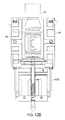
- FIGS. 12A-12B illustrate an exemplary embodiment of using a base assembly to form a container base according to the present invention.
- FIGS. 13A-13B illustrate exemplary embodiments of a push rod repositioning the container base according to the present invention.
- FIGS. 14A-14B illustrate an exemplary embodiment of a container prior to and after repositioning according to the present invention.
- Exemplary embodiments of the present invention may generally relate to a container, a method of inverting a grip of a container, and a blow molding apparatus for forming a container having an invertible grip.
- a blow-molding apparatus 10 may receive a parison 12 and enclose the parison with a mold 14 a - c , which may include a recess 16 in the outer surface of the mold 14 b .
- the blow-molding apparatus 10 may inflate the parison into the mold to form a blow molded container 100 (see FIG. 5 ).
- the blow-molded container 100 may have a sidewall, a movable region 18 formed at the recess 16 , and a hinge circumscribing an interface between the sidewall of container 100 and the movable region 18 .
- the blow-molding apparatus may be adapted to move the movable region 18 about the hinge before filling the blow molded container 100 .
- An internal volume of the blow molded container may be reduced by moving the movable region 18 into the center of the container 100 (arrow 22 in FIGS. 6 and 7A ) as schematically shown in FIG. 7C .
- the movable region 18 may form a grip for the container 100 .
- FIG. 1 illustrates an exemplary embodiment of a container representing the shape of the container as stretch blow molded according to the present invention
- FIG. 2 illustrates an exemplary embodiment of a movable region of a container in its outwardly blown position according to the present invention
- FIGS. 3A-B illustrate an exemplary embodiment of the movable region of a container in its outwardly blown position and the final configuration of the grip according to the present invention, respectively.
- FIG. 1 illustrates a perspective side view of the exemplary container 100 according to an exemplary embodiment of the present invention.
- the container 100 includes an upper portion 102 , a shoulder 104 , a container body 106 , and a base 108 .
- the upper portion 102 of the container 100 generally is any structure having an opening into the interior of the container 100 and being adapted to receive a closure (not shown).
- the closure may be any device used to create a substantially air tight seal for a hot-filled product within the container 100 , thus substantially preventing air from entering the container 100 through the upper portion 102 .
- the upper portion 102 includes threads 112 that are adapted to couple with a closure that is a twist-on cap. The cap may be twisted onto the threads 112 of the upper portion 102 to create a seal with the container 100 .
- a sealing plug may be placed in the upper portion 102 to seal the container 100 .
- Other closures or seals may be used, as will be appreciated by those of skill in the art.
- the shoulder 104 of the container 100 extends from the top of the container body 106 to the bottom of the upper portion 102 . Generally, the shoulder 104 narrows as it progresses from the container body 106 to the bottom of the upper portion 102 .
- the shoulder 104 may have any desired shape, or may be omitted from the container 100 .
- the shoulder 104 may include patterns, shapes, and other geometries, or alternatively, may be substantially smooth. In the depicted embodiment, the width of the bottom of the shoulder 104 corresponds to the width of the top of the container body 106 , and narrows by curving inward as the shoulder 104 approaches the upper portion 102 .
- the shoulder 104 curves outward before reaching the upper portion 102 , and then curves inward as the shoulder 104 reaches the upper portion 102 .
- the shoulder 104 may be other shapes and include other patterns, as will be appreciated by those of skill in the art.
- the container body 106 of the container 100 extends from the base 108 to the shoulder 104 and defines an interior of the container 100 .
- the container body 106 is positioned below the shoulder 104 .
- the container body 106 extends to the upper portion 102 .
- the container body 106 may be any asymmetrical or symmetrical shape, such as, but not limited to, cylindrical, square, rectangular, or other geometries.
- the container body 106 of the container 100 may include patterned support structure or vacuum panels. The patterned support structure and the vacuum panels may help provide structural integrity for the container 100 .
- the container body 106 has ribs 112 positioned at various locations on the container 100 .
- the ribs 112 may be a series of recessed sections alternating with non-recessed sections on the container body 106 .
- the ribs 112 may include other types and shapes and may also be placed at alternate locations on the container body 106 , as will be appreciated by those of skill in the art.
- the ribs 112 may also be omitted from the container body 106 , or may be placed at other locations on the container 100 .
- the container body 106 may also include a movable region 110 that initially is blow molded outside of the container 100 (see FIG. 6 ).
- the movable region 110 is comprised of a number of surfaces in the grip area of the container body 106 .
- the number of surfaces are arranged in a way so that an external force (arrow 22 ) acting on the grip area causes the surfaces to fold in relation to one another until such a point where they snap into an inverted position toward the interior of the container 100 . As depicted in FIG.
- the movable region 110 may include a first hinge or seam 202 , a first portion 204 , a first inner wall 206 , a second hinge or seam 214 , a second portion 212 , a second inner wall 210 , a third hinge or seam 208 , a fourth hinge or seam 216 , and a fifth hinge or seam 218 .
- the first hinge or seam 202 couples the first portion 204 so that portion 204 of the container body 106 is initially blow molded outside the container body 106 and then can be pushed inside the container as shown in FIGS. 3A-B , respectively.
- the second hinge or seam 214 couples the second portion 212 so that second portion 212 can be pushed inside the container 106 by pivoting about second hinge or seam 214 .
- the fifth hinge or seam 218 couples the first portion 204 with the first inner wall 206
- the fourth hinge or seam 216 couples the second portion 212 with the second inner wall 210 so that these portions can be pushed inside container 106 .
- the inverted movable region 110 is shown in FIG. 3B .
- the mold of the container forming assembly shown in FIGS. 4-6 may be made of first and second mold halves 14 a , 14 b that each may include a wall with a recess to form respective first and second movable gripping regions 110 .
- the gripping-regions 110 are initially blown outside the container and then inverted so that a consumer's hand easily fits into the inverted gripping regions.
- FIG. 3A illustrates the movable region 110 as blow molded extending away from the interior of the container 100
- FIG. 3B illustrates the movable region 110 extending toward the interior of the container 100 after inversion.
- a force may be applied to cause the movable region 110 to invert.
- the first portion 204 rotates about the first hinge or seam 202 and the second portion 212 rotates about the second hinge or seam 214 .
- first portion 204 rotates about the fifth hinge or seam 218 relative to the first inner wall 206
- second portion 212 rotates about the fourth hinge or seam 216 relative to the second inner wall 210
- first inner wall 206 rotates about the third hinge or seam 208 relative to the second inner wall 210 . That is, a many sided movable region 110 is initially blown outside the container thereby avoiding the need for a mold with a deep-set protrusion around which plastic material has difficulty forming the desired thickness about the protrusion.
- the weights of the plastic at the hinges or seams along with the angles of the first and second portions and the inner walls are designed so that movable region 110 can be inverted into the container to form a deep-set grip(s) that a consumer can securely grip and that has a good ergonomic feel to the consumer.
- the container wall thickness at the hinges is thinner than the surrounding portions or inner walls, which are heavier as the plastic naturally moves in this manner.
- the angles of the first and second portions and the inner walls should be sufficiently steep so that the desired depth of a grip is achieved and the desired ergonomic feel.
- a sufficient force may be applied to the movable region 110 formed outside the container while the container 100 remains within the mold 14 a - c (see FIG. 5 ).
- the inversion of the moveable region 18 may occur as late into the blowing process as possible so that the container 100 is allowed to cool as much possible before the container 100 is released or ejected from the mold. The longer the container and movable region can cool, a better inversion result can be achieved.
- the inversion may occur just before the container is ejected or released from the mold to reduce the likelihood that the inversion will form unwanted creases or deformities in the container 100 .
- An air cylinder (not shown) may be used for the inversion of the movable region 110 by applying a force to the first portion 204 and to second inner wall 210 .
- other mechanical, pneumatic, hydraulic, or cam operated means for inverting may be used, as will be appreciated by those skilled in the art.
- the cam operated means may be included within the mold and the movable region may be inverted while the mold fully encloses the formed container.
- the container 100 is blow molded into the shape depicted in FIG. 3A to avoid trapping material in recessed areas of a complex shaped mold and to improve the performance (less rejected containers) of the container 100 at the movable region 110 without increasing the amount of material to the region.
- the movable region 110 is formed into the shape shown in FIG. 3A to ensure that all surfaces of the movable region are properly formed with sufficient amounts of material and have sufficient definition.
- An advantage of forming the movable region 110 extending away from the interior of the container is that the rigidity at the movable region 110 is increased by allowing for further orientation of plastic material during the blow molding process (see FIGS.
- the movable region 110 would not be fully formed at the region near the first hinge or seam 202 and near the second hinge or seam 212 .
- gas stretches plastic material against a mold for the container, such as a mold for the container 100 . If the mold contains a protrusion to form the movable region depicted in FIG. 3B , the plastic material would have to stretch around the protrusion from third hinge or seam 208 down to the region near the first hinge or, seam 202 and near the second hinge or seam 212 (see FIG. 3B ).
- the contact with the mold would trap material at the region near the third hinge or seam 208 , and not allow the material to fully form down into the region near the first hinge or seam 202 and near the second hinge or seam 212 . Moreover, forming the movable region 110 with such a protrusion would cause plastic to become trapped at the movable region 110 , which may prevent other areas of the container to not have sufficient plastic to properly form those areas.
- Stretch blow molding the container 100 into the shape as illustrated in FIGS. 1 , 2 , and 3 B also reduces the wall thickness of the movable region 110 and reduces the occurrence of thick amorphous plastic sections near the movable region 110 , as compared with forming the container with the movable region 110 extending outwardly from the container as depicted in FIG. 3A .
- This may allow the amount of plastic material present in the movable region 110 to be reduced without detrimentally affecting container performance, and, in some instances, this technique improves the performance of the movable region.
- forming the container into the shape as illustrated in FIG. 3A may allow a more uniform distribution of plastic material in the base 108 .
- the increased rigidity may allow for the inversion of the movable region 110 without a substantial net distortion of the container body 106 .
- FIGS. 4-6 schematically illustrate a container forming assembly for forming a container from a parison according to one embodiment of the invention.
- the assembly includes a mold 14 a , 14 b , and 14 c that can be driven by a drive mechanism to enclose parison 12 .
- a container 100 is blown within the closed mold assembly, as shown in FIG. 5 .
- a recess 16 may be disposed in a sidewall of mold 14 a and mold 14 b to form a two sided grip for a container.
- FIG. 8 illustrates one side of the mold 814 for forming a container as shown in FIG. 1 .
- each side mold would include a recess 816 that has a first surface 804 adapted to form a first outer grip portion ( 204 ), a second surface 812 adapted to form a second outer grip portion ( 212 ), a third surface 806 adapted to form a first inner grip portion ( 206 ) adjacent the first outer grip portion ( 204 ), a fourth surface 810 adapted to form a second inner grip portion ( 210 ), and a fifth surface area 808 adapted to from a ridge area ( 208 ) of a movable gripping region 110 .
- the forming assembly may include a first push rod adapted to rotate the first portion 204 of a movable region 110 about first hinge or seam 202 to invert the movable region so that it forms a gripping region.
- a second push rod may be employed to cause the second portion 212 to rotate about hinge or seam 214 to push both sides of the resultant gripping regions within container 100 prior to filling the container with food product.
- a section 900 of the recess 816 that corresponds with surfaces 806 and 810 and surface area 808 is movable between the inactive position shown in FIG. 8 and the active position shown in FIG. 9 .
- This system also benefits from requiring less expensive components. While other systems may use complex pneumatic, hydraulic, or cam operated means to push pieces of the mold inward at a specific point in the blow molding cycle, the exemplary embodiments may use a simple mechanical means of inverting the movable region 110 . This reduces the cost, molding time, and complexity of the mold set up as compared with conventional systems.
- the container 100 may improve the sufficient rigidity, definition, and performance of the container 100 at a movable region 110 thereby allowing a container to be formed that uses less plastic while maintaining the performance and appearance of the container.
- the embodiments and examples discussed herein are non-limiting examples.
- the shape of the inset are not limited to the examples shown, as the movable region may blown outward in a round or oval forum and, when inverted, still obtain the same function—decrease the volume of the blown container.
- FIGS. 11A-11D illustrate an exemplary embodiment of a base assembly 400 according to the present invention.
- FIG. 11A illustrates a side view of the base assembly 400 having a push rod 446 .
- FIG. 11B illustrates a side view of the base assembly 400 with a rod end 412 of the push rod 426 extended.
- FIG. 11C illustrates a top view of the base assembly 400 .
- FIG. 11D illustrates a cross sectional view of the base assembly 400 along line A-A of FIG. 11C to further depict the push rod 426 .
- FIGS. 11A-11D will be made.
- the base assembly 400 includes a base pedestal 402 , a base plug 404 , a centering pin 420 , and a push rod 426 .
- the centering pin 420 may be used to secure and position the base assembly 400 in a blow molding apparatus (not shown).
- the base pedestal 402 may have any shape, so long as it has a hollow central region for receiving the push rod 426 , and a top region adapted to connect with the base plug 404 .
- the base plug 404 and the base pedestal 402 may be a single apparatus.
- the base assembly 400 is raised to connect with other mold assemblies for blow molding of a container. After the container is blow molded, the base assembly 400 is lowered to release the container.
- the push rod 426 is a cylindrically shaped rod that is located above the centering pin 420 and extends through the base pedestal 402 up to a surface of the base plug 404 .
- the push rod 426 is a metal mold component.
- the base assembly 400 includes a mechanism that moves the push rod 426 and elevates a rod end 412 of the push rod 426 above the surface of the base plug 404 . In an alternative embodiment, only the rod end 412 of the push rod 426 may be elevated.
- the mechanism for elevating the push rod 426 may be a spring, a cam, or may be driven pneumatically, hydraulically, or electronically. The mechanism may be located internal or external to the push rod 426 .
- the rod end 412 is formed at the end of the push rod 426 , and the top surface of the rod end 412 is used to form a dimple in the base of the container.
- the shape of the rod end 412 is similar to a truncated cone, where the end of the truncated cone includes a section 418 .
- the section 418 of the rod end 412 may be concave, and the section 418 may be adapted to form a convex section in the base of the container that extends downward away from the center of the container.
- the section 418 of the rod end 412 may be flat or convex extending upward toward the center of the container.
- the section 418 is used to reposition a moveable region of the base from an initially outward protruding position to a position within the container cavity, as will be discussed later in detail.
- the base plug 404 includes a base mold 406 having a contact surface 408 adapted to contact a parison material during blow molding of a container.
- the contact surface 408 of the base mold 406 forms the shape of the base of the container.
- the contact surface 406 is a curvilinear mold for forming a moveable region and a bearing surface of a container base.
- the moveable region of the base is repositioned from an outwardly protruding position toward the interior of the container.
- the movable region is repositioned to a position within the interior of the container, thus forming a container base that is structurally and functionally similar to that of a container having a conventional push up.
- the contact surface 408 includes a cavity 410 , a surface 414 , and a surface of the rod end 412 .
- the surface of the cavity 410 and the surface of the rod end 412 form an inner region 420 of the base mold 406
- the surface 414 forms an outer region 422 of the base mold 406 , with the outer region 422 being offset from the inner region 420 .
- the inner region 420 and the outer region 422 are adapted to form a base of a container during blow molding.
- the outer region 422 is substantially flat and is adapted to form a bearing surface of a container. In an alternative embodiment, the outer region 422 may be non-flat or rounded, or may form a discontinuous bearing surface.
- the present invention can thus be adapted to form bearing surfaces with geometries known in the art.
- the cavity 410 is a depression in the base mold 406 that is adapted to form a moveable region in a container.
- the cavity 410 begins at the outermost edge of the inner region 420 , and curves both inward toward the center of the base mold 406 and downward toward the bottom of the base assembly 400 .
- the cavity 410 Prior to reaching the rod end 412 , the cavity 410 reaches its bottom and begins to curve upward. From the bottom of the cavity 410 , the cavity 410 curves both inward toward the center of the base mold 406 and upward away from the bottom of the base assembly 400 .
- the cavity 410 ends at the truncated end of the rod end 412 .
- the bottom of the rod end 412 may occur at other locations in the base mold 406 relative to the rod end 412 , or may even be positioned on the rod end 412 .
- the cavity 410 is a circular depression in the base mold 406 (see FIG. 11C ).
- the cavity 410 is located between the outermost edge of the inner region 420 and the outermost edge of section 418 of the rod end 412 .
- the cavity 410 may be any symmetric or asymmetric shape other than a circular depression.
- the cavity may form a triangle, a rectangle, or a polygon.
- the cavity 410 does not curve upward from its bottom, and instead may curve further downward or may be flat until it reaches the center of the base mold 406 .
- FIGS. 12A-12B illustrate an exemplary embodiment using a base assembly 400 to form a base of a container according to the present invention.
- a parison 304 having a threaded finish is attached to a holder 302 of a blow molding apparatus (not shown) that is adapted to form a blow molded container.
- a first side mold 306 Surrounding the parison 304 is a first side mold 306 , a second side mold 308 , and the base assembly 400 .
- the first side mold 306 contains a mold of one side of the container, and the second side mold 308 contains a mold of the other side.
- the first side mold 306 and the second side mold 308 may be mirror images of one another, or they may have different shapes. Other combinations and different numbers of molds may be used, as is understood by those of skill in the art.
- the parison 304 Prior to blow molding, the parison 304 is enclosed by the first side mold 306 , the second side mold 308 , and the base mold 206 . As illustrated in FIG. 12B , once the parison is enclosed, gas is forced into the parison 304 to inflate the parison 304 in the first side mold 306 , the second side mold 308 , and the base mold 206 . During inflation, the parison 304 stretches into the form of the first side mold 306 , the second side mold 308 , and the base mold 406 . As the parison material contacts the base mold 406 , the parison material is blown against the contact surface 408 into the cavity 410 . The parison material stretches into the cavity 410 to form a moveable region in the base of the container.
- the parison material does not encounter a deep protrusion, which would cause cooling and would reduce plastic material orientation. Stretching the parison material during inflation into the cavity 410 , as opposed to around a protrusion, allows the parison material to further stretch and orient since the parison material is blown into a wider space as compared with a narrow recess around a deep protrusion. The additional stretch increases the crystallinity of the molecules of the parison material, which increases the rigidity of the base and improves the structural integrity of the base. Blow molding the parison material into the cavity 410 also reduces the wall thickness of the base and reduces the occurrence of thick amorphous plastic sections in the base. Thus, the amount of plastic material present in the base can be reduced without detrimentally affecting container performance, and, in some instances, this technique improves the performance of the base.
- FIG. 13A illustrates an exemplary embodiment of the push rod 426 repositioning the base of the container according to the present invention.
- the base of the container prior to separating the first side mold 306 , the second side mold 308 , and the base assembly 400 from the container, the base of the container is repositioned.
- a base having a moveable region that protrudes outward from the container is formed at the cavity 410 .
- the moveable region of the container base is downwardly convex with respect to a bearing surface, as is described below in detail.
- the push rod 426 is then elevated upward toward the center of the container to elevate the rod end 412 above the contact surface 408 to exert pressure on the moveable region of the base.
- the moveable region is forced upward toward the center of the container into an upward position, which extends inward into the interior of the container with respect to the bearing surface.
- the push rod 426 may be lowered. Thereafter, the first side mold 306 , the second side mold 308 , and the base assembly 400 may release the blow molded container by separating.
- FIG. 13B illustrates an alternative exemplary embodiment of the push rod 426 repositioning the base of the container according to the present invention.
- the base assembly 400 separates from the first side mold 306 and the second side mold 308 to release the base of the container. Afterwards, the rod end 412 is elevated until it reaches the moveable region of the container base. The rod end 412 then exerts pressure on the base of the container to reposition the moveable region of the base. Thereafter, the first side mold 306 and the second side mold 308 may release the blow molded container by separating so that the container may be further processed. In still other embodiments, the base of the container may be released from the molds without being repositioned and sent to a different device for repositioning the moveable region.
- FIGS. 14A and 14B illustrate an exemplary embodiment of a container 500 prior to and after repositioning by the push rod 406 according to the present invention.
- the base Prior to repositioning, the base includes a moveable region 502 and a bearing surface 504 , where at least a portion of the moveable region 502 protrudes outward from the base of the container beyond the bearing surface 504 .
- the moveable region 502 of the container base is downwardly convex with respect to the bearing surface 504 .
- the moveable region 502 is formed by the inner region 420 of the base mold 406
- the bearing surface 504 is formed by the outer region 422 .
- the moveable region 502 protrudes outward from an innermost edge of the bearing surface 504 away from the center of the container and is downwardly convex with respect to the bearing surface 504 .
- the moveable region 502 is illustrated as being circular, but may be any symmetrical or asymmetrical shape.
- a dimple 518 is formed at a center of the moveable region 502 by the surface of the rod end 412 of the contact surface 408 .
- the dimple 518 is upwardly convex and protrudes inward toward the center of the container 500 .
- the dimple 518 provides a pocket in which the rod end 412 can be situated as the push rod 426 extends to reposition the moveable region 502 of the base.
- the moveable region 502 is moved toward the center interior of the container by the extension of the rod end 412 .
- the moveable region 502 is moved within the interior of the container with respect to the bearing surface 504 .
- the rod end 412 contacts the dimple 518 and forces the dimple 518 toward the center of the container. This repositions the moveable region 502 and causes the moveable region 502 to no longer extend or protrude beyond the bearing surface 504 .
- the rod end 412 may contact the moveable region 502 at other locations to reposition the moveable region 502 of the base, as would be understood by those of ordinary skill in the art.
- repositioning of the base occurs before the container is filled so that the container may be placed on a substantially flat surface for transport to, for example, a filling machine, or alternatively, for transport during manufacturing or for palletizing, as is known in the art.
- the filling machine may fill the container by any known filling process, including hot filling, cold filling, and other filling processes known by those skilled in the art.
- the container 500 has a one-piece construction and can be prepared from a monolayer plastic material, such as a polyamide, for example, nylon; a polyolefin such as polyethylene, for example, low density polyethylene (LDPE) or high density polyethylene (HDPE), or polypropylene; a polyester, for example polyethylene terephthalate (PET), polyethylene naphtalate (PEN); or others, which can also include additives to vary the physical or chemical properties of the material. For example, some plastic resins can be modified to improve the oxygen permeability.
- the container 500 can be prepared from a multilayer plastic material.
- the layers can be any plastic material, including virgin, recycled and reground material, and can include plastics or other materials with additives to improve physical properties of the container.
- EVOH ethylvinyl alcohol
- tie layers or binders to hold together materials that are subject to delamination when used in adjacent layers.
- a coating may be applied over the monolayer or multilayer material, for example to introduce oxygen barrier properties.
- parison 304 may also be a threadless plastic tube without departing from the scope of the invention.
- a parison that is a plastic tube involves inserting a needle into the parison, and forcing gas through the needle to expand the plastic tube to take the shape of a mold.
- any blow molding technique may be used for forming the container, including injection blow molding, stretch blow molding, or extrusion blow molding, as would be understood by those of skill in the art.
- the detailed description describes a technique for blow molding a moveable region 502 on a container base by molding a parison material into a cavity 410 .
- this technique may be used to form other regions of a container other than the base, such as to form at least a portion of a hand grip of a container, or to form other deep protrusions of a container.
- the cavity 410 may also be located on either side mold 306 or 308 , or on other locations in the base mold 406 .
- This technique is useable on any region of a plastic container where a deep protrusion is required.
- the technique described herein increases the rigidity of a region having a deep protrusion, while reducing thick amorphous plastic sections around the region caused by the deep protrusion.
Abstract
Description
Claims (24)
Priority Applications (1)
| Application Number | Priority Date | Filing Date | Title |
|---|---|---|---|
| US12/856,484 US8323555B2 (en) | 2006-04-07 | 2010-08-13 | System and method for forming a container having a grip region |
Applications Claiming Priority (2)
| Application Number | Priority Date | Filing Date | Title |
|---|---|---|---|
| US11/399,430 US8017065B2 (en) | 2006-04-07 | 2006-04-07 | System and method for forming a container having a grip region |
| US12/856,484 US8323555B2 (en) | 2006-04-07 | 2010-08-13 | System and method for forming a container having a grip region |
Related Parent Applications (1)
| Application Number | Title | Priority Date | Filing Date |
|---|---|---|---|
| US11/399,430 Continuation US8017065B2 (en) | 2005-04-15 | 2006-04-07 | System and method for forming a container having a grip region |
Publications (2)
| Publication Number | Publication Date |
|---|---|
| US20100301524A1 US20100301524A1 (en) | 2010-12-02 |
| US8323555B2 true US8323555B2 (en) | 2012-12-04 |
Family
ID=38574379
Family Applications (4)
| Application Number | Title | Priority Date | Filing Date |
|---|---|---|---|
| US11/399,430 Active 2029-01-14 US8017065B2 (en) | 2005-04-15 | 2006-04-07 | System and method for forming a container having a grip region |
| US12/627,922 Active 2026-09-10 US8162655B2 (en) | 2006-04-07 | 2009-11-30 | System and method for forming a container having a grip region |
| US12/856,484 Active 2026-08-01 US8323555B2 (en) | 2006-04-07 | 2010-08-13 | System and method for forming a container having a grip region |
| US12/856,516 Active US10118331B2 (en) | 2006-04-07 | 2010-08-13 | System and method for forming a container having a grip region |
Family Applications Before (2)
| Application Number | Title | Priority Date | Filing Date |
|---|---|---|---|
| US11/399,430 Active 2029-01-14 US8017065B2 (en) | 2005-04-15 | 2006-04-07 | System and method for forming a container having a grip region |
| US12/627,922 Active 2026-09-10 US8162655B2 (en) | 2006-04-07 | 2009-11-30 | System and method for forming a container having a grip region |
Family Applications After (1)
| Application Number | Title | Priority Date | Filing Date |
|---|---|---|---|
| US12/856,516 Active US10118331B2 (en) | 2006-04-07 | 2010-08-13 | System and method for forming a container having a grip region |
Country Status (1)
| Country | Link |
|---|---|
| US (4) | US8017065B2 (en) |
Cited By (13)
| Publication number | Priority date | Publication date | Assignee | Title |
|---|---|---|---|---|
| US8627944B2 (en) | 2008-07-23 | 2014-01-14 | Graham Packaging Company L.P. | System, apparatus, and method for conveying a plurality of containers |
| US8671653B2 (en) | 2003-07-30 | 2014-03-18 | Graham Packaging Company, L.P. | Container handling system |
| US8747727B2 (en) | 2006-04-07 | 2014-06-10 | Graham Packaging Company L.P. | Method of forming container |
| US8919587B2 (en) | 2011-10-03 | 2014-12-30 | Graham Packaging Company, L.P. | Plastic container with angular vacuum panel and method of same |
| US8962114B2 (en) | 2010-10-30 | 2015-02-24 | Graham Packaging Company, L.P. | Compression molded preform for forming invertible base hot-fill container, and systems and methods thereof |
| US9022776B2 (en) | 2013-03-15 | 2015-05-05 | Graham Packaging Company, L.P. | Deep grip mechanism within blow mold hanger and related methods and bottles |
| US9150320B2 (en) | 2011-08-15 | 2015-10-06 | Graham Packaging Company, L.P. | Plastic containers having base configurations with up-stand walls having a plurality of rings, and systems, methods, and base molds thereof |
| US9522749B2 (en) | 2001-04-19 | 2016-12-20 | Graham Packaging Company, L.P. | Method of processing a plastic container including a multi-functional base |
| US9707711B2 (en) | 2006-04-07 | 2017-07-18 | Graham Packaging Company, L.P. | Container having outwardly blown, invertible deep-set grips |
| US9994378B2 (en) | 2011-08-15 | 2018-06-12 | Graham Packaging Company, L.P. | Plastic containers, base configurations for plastic containers, and systems, methods, and base molds thereof |
| US9993959B2 (en) | 2013-03-15 | 2018-06-12 | Graham Packaging Company, L.P. | Deep grip mechanism for blow mold and related methods and bottles |
| US10035690B2 (en) | 2009-01-06 | 2018-07-31 | Graham Packaging Company, L.P. | Deformable container with hoop rings |
| US10118331B2 (en) | 2006-04-07 | 2018-11-06 | Graham Packaging Company, L.P. | System and method for forming a container having a grip region |
Families Citing this family (33)
| Publication number | Priority date | Publication date | Assignee | Title |
|---|---|---|---|---|
| US10246238B2 (en) | 2000-08-31 | 2019-04-02 | Co2Pac Limited | Plastic container having a deep-set invertible base and related methods |
| US7900425B2 (en) | 2005-10-14 | 2011-03-08 | Graham Packaging Company, L.P. | Method for handling a hot-filled container having a moveable portion to reduce a portion of a vacuum created therein |
| NZ521694A (en) | 2002-09-30 | 2005-05-27 | Co2 Pac Ltd | Container structure for removal of vacuum pressure |
| US8584879B2 (en) | 2000-08-31 | 2013-11-19 | Co2Pac Limited | Plastic container having a deep-set invertible base and related methods |
| US8127955B2 (en) | 2000-08-31 | 2012-03-06 | John Denner | Container structure for removal of vacuum pressure |
| US8381940B2 (en) | 2002-09-30 | 2013-02-26 | Co2 Pac Limited | Pressure reinforced plastic container having a moveable pressure panel and related method of processing a plastic container |
| US10435223B2 (en) | 2000-08-31 | 2019-10-08 | Co2Pac Limited | Method of handling a plastic container having a moveable base |
| EP1387804A4 (en) | 2001-04-19 | 2005-03-02 | Graham Packaging Co | Multi-functional base for a plastic wide-mouth, blow-molded container |
| US9969517B2 (en) | 2002-09-30 | 2018-05-15 | Co2Pac Limited | Systems and methods for handling plastic containers having a deep-set invertible base |
| US6922153B2 (en) * | 2003-05-13 | 2005-07-26 | Credo Technology Corporation | Safety detection and protection system for power tools |
| CA2559319C (en) | 2004-03-11 | 2014-05-06 | Philip Sheets | Process and a device for conveying odd-shaped containers |
| US10611544B2 (en) | 2004-07-30 | 2020-04-07 | Co2Pac Limited | Method of handling a plastic container having a moveable base |
| US8075833B2 (en) | 2005-04-15 | 2011-12-13 | Graham Packaging Company L.P. | Method and apparatus for manufacturing blow molded containers |
| US9598533B2 (en) | 2005-11-22 | 2017-03-21 | Eastman Chemical Company | Polyester compositions containing cyclobutanediol having a certain combination of inherent viscosity and moderate glass transition temperature and articles made therefrom |
| US7799264B2 (en) | 2006-03-15 | 2010-09-21 | Graham Packaging Company, L.P. | Container and method for blowmolding a base in a partial vacuum pressure reduction setup |
| US11731823B2 (en) | 2007-02-09 | 2023-08-22 | Co2Pac Limited | Method of handling a plastic container having a moveable base |
| US11897656B2 (en) | 2007-02-09 | 2024-02-13 | Co2Pac Limited | Plastic container having a movable base |
| EP2103413B1 (en) * | 2008-03-18 | 2012-08-01 | The Procter & Gamble Company | A process for making a stretch-blow moulded container having an integrally moulded handle |
| EP2168752B1 (en) * | 2008-09-30 | 2015-01-14 | The Procter & Gamble Company | Stretch blow molding process and container |
| GB0818830D0 (en) * | 2008-10-14 | 2008-11-19 | G2 Design Consultants Ltd | Plastics container |
| US8636944B2 (en) | 2008-12-08 | 2014-01-28 | Graham Packaging Company L.P. | Method of making plastic container having a deep-inset base |
| ATE536247T1 (en) * | 2009-09-04 | 2011-12-15 | Procter & Gamble | METHOD FOR MAKING A STRETCH BLOW MOLDING CONTAINER HAVING A MOLDED HANDLE |
| GB0918744D0 (en) * | 2009-10-26 | 2009-12-09 | Nampak Plastics Europe Ltd | Plastic container |
| US9133006B2 (en) | 2010-10-31 | 2015-09-15 | Graham Packaging Company, L.P. | Systems, methods, and apparatuses for cooling hot-filled containers |
| US8556097B2 (en) * | 2011-02-16 | 2013-10-15 | Amcor Limited | Container having vacuum panel with balanced vacuum and pressure response |
| US8668101B2 (en) | 2011-03-23 | 2014-03-11 | Mid-America Machining, Inc. | Method and apparatus for making a light weight container |
| US20120318767A1 (en) * | 2011-06-01 | 2012-12-20 | Eastman Chemical Company | High strength bottle |
| US20120305575A1 (en) * | 2011-06-01 | 2012-12-06 | Eastman Chemical Company | High strength bottle |
| EP3112280B1 (en) * | 2011-12-27 | 2018-10-24 | Yoshino Kogyosho Co., Ltd. | Process for molding a bottle container of a pinch-grip type |
| US20130217830A1 (en) | 2012-02-16 | 2013-08-22 | Eastman Chemical Company | Clear Semi-Crystalline Articles with Improved Heat Resistance |
| WO2015134429A1 (en) * | 2014-03-03 | 2015-09-11 | Amcor Limited | Machine component facilitating mold base movement |
| ES2962408T3 (en) * | 2019-01-29 | 2024-03-18 | Amcor Rigid Packaging Usa Llc | Vertical displacement devices and methods for mechanically inverting a thermoplastic container base |
| US20220297906A1 (en) * | 2021-03-16 | 2022-09-22 | Altria Client Services Llc | Tray with base, dome and brim |
Citations (239)
| Publication number | Priority date | Publication date | Assignee | Title |
|---|---|---|---|---|
| US110624A (en) | 1871-01-03 | Improvement in cutters for nail-cutting machines | ||
| US1499239A (en) | 1922-01-06 | 1924-06-24 | Malmquist Machine Company | Sheet-metal container for food |
| US2124959A (en) | 1936-08-08 | 1938-07-26 | Vogel William Martin | Method of filling and closing cans |
| US2142257A (en) | 1937-01-16 | 1939-01-03 | Saeta Samuel | Apparatus for filling containers |
| US2378324A (en) | 1941-05-22 | 1945-06-12 | Kraft Cheese Company | Packaging machine |
| GB781103A (en) | 1955-02-11 | 1957-08-14 | Internat Patents Trust Ltd | Improvements in dispensing containers |
| DE1761753U (en) | 1957-11-14 | 1958-02-20 | Josef Werny Fa | TABLE. |
| US2880902A (en) | 1957-06-03 | 1959-04-07 | Owsen Peter | Collapsible article |
| US2960248A (en) | 1959-03-20 | 1960-11-15 | Arthur L Kuhlman | Block type containers |
| US2971671A (en) | 1956-10-31 | 1961-02-14 | Pabst Brewing Co | Container |
| US2982440A (en) | 1959-02-05 | 1961-05-02 | Crown Machine And Tool Company | Plastic container |
| US3043461A (en) | 1961-05-26 | 1962-07-10 | Purex Corp | Flexible plastic bottles |
| US3081002A (en) | 1957-09-24 | 1963-03-12 | Pfrimmer & Co J | Containers for medicinal liquids |
| US3090478A (en) | 1960-08-19 | 1963-05-21 | Kartridg Pak Co | Container carrier |
| US3142371A (en) | 1960-02-19 | 1964-07-28 | Burton Machine Corp John | Spotting device for bottles and the like |
| US3174655A (en) | 1963-01-04 | 1965-03-23 | Ampoules Inc | Drop or spray dispenser |
| US3198861A (en) | 1961-08-25 | 1965-08-03 | Continental Can Co | Method of forming a thermoplastic bottle having a convex reversible curvature at the bottom |
| US3201111A (en) * | 1963-11-12 | 1965-08-17 | Afton Leonard | Multi-purpose, inherently biased, selfinflatable bellows |
| US3301293A (en) | 1964-12-16 | 1967-01-31 | Owens Illinois Inc | Collapsible container |
| US3325031A (en) | 1964-09-14 | 1967-06-13 | Fr Des Lab Labaz Soc | Bottles of flexible material for medicinal products |
| GB1113988A (en) | 1964-07-01 | 1968-05-15 | Charles Tennant & Company Ltd | Improvements in or relating to containers |
| US3397724A (en) | 1966-06-03 | 1968-08-20 | Phillips Petroleum Co | Thin-walled container and method of making the same |
| US3409167A (en) | 1967-03-24 | 1968-11-05 | American Can Co | Container with flexible bottom |
| US3417893A (en) | 1967-05-23 | 1968-12-24 | Heiman G. Lieberman | Container closure |
| US3426939A (en) | 1966-12-07 | 1969-02-11 | William E Young | Preferentially deformable containers |
| FR1571499A (en) | 1968-05-07 | 1969-06-20 | ||
| US3468443A (en) | 1967-10-06 | 1969-09-23 | Apl Corp | Base of plastic container for storing fluids under pressure |
| US3483908A (en) | 1968-01-08 | 1969-12-16 | Monsanto Co | Container having discharging means |
| US3485355A (en) | 1968-07-03 | 1969-12-23 | Stewart Glapat Corp | Interfitting stackable bottles or similar containers |
| US3693828A (en) | 1970-07-22 | 1972-09-26 | Crown Cork & Seal Co | Seamless steel containers |
| US3704140A (en) | 1968-12-30 | 1972-11-28 | Carnaud & Forges | Sterilisation of tins |
| US3727783A (en) | 1971-06-15 | 1973-04-17 | Du Pont | Noneverting bottom for thermoplastic bottles |
| US3819789A (en) | 1969-06-11 | 1974-06-25 | C Parker | Method and apparatus for blow molding axially deformable containers |
| US3904069A (en) | 1972-01-31 | 1975-09-09 | American Can Co | Container |
| US3918920A (en) | 1974-01-07 | 1975-11-11 | Beckman Instruments Inc | Holder for sample containers of different sizes |
| US3935955A (en) | 1975-02-13 | 1976-02-03 | Continental Can Company, Inc. | Container bottom structure |
| US3941237A (en) | 1973-12-28 | 1976-03-02 | Carter-Wallace, Inc. | Puck for and method of magnetic conveying |
| US3942673A (en) | 1974-05-10 | 1976-03-09 | National Can Corporation | Wall construction for containers |
| US3949033A (en) | 1973-11-02 | 1976-04-06 | Owens-Illinois, Inc. | Method of making a blown plastic container having a multi-axially stretch oriented concave bottom |
| US3956441A (en) | 1974-09-16 | 1976-05-11 | Owens-Illinois, Inc. | Method of making a blown bottle having a ribbed interior surface |
| US4036926A (en) | 1975-06-16 | 1977-07-19 | Owens-Illinois, Inc. | Method for blow molding a container having a concave bottom |
| US4037752A (en) | 1975-11-13 | 1977-07-26 | Coors Container Company | Container with outwardly flexible bottom end wall having integral support means and method and apparatus for manufacturing thereof |
| US4117062A (en) | 1977-06-17 | 1978-09-26 | Owens-Illinois, Inc. | Method for making a plastic container adapted to be grasped by steel drum chime-handling devices |
| US4123217A (en) | 1974-11-30 | 1978-10-31 | Maschinenfabrik Johann Fischer | Apparatus for the manufacture of a thermoplastic container with a handle |
| US4125632A (en) | 1976-11-22 | 1978-11-14 | American Can Company | Container |
| US4158624A (en) | 1977-03-21 | 1979-06-19 | Ti Fords Limited | Apparatus for deflecting bottles in bottle feeding apparatus |
| US4174782A (en) | 1977-02-04 | 1979-11-20 | Solvay & Cie | Hollow body made from a thermoplastic |
| US4219137A (en) | 1979-01-17 | 1980-08-26 | Hutchens Morris L | Extendable spout for a container |
| US4231483A (en) | 1977-11-10 | 1980-11-04 | Solvay & Cie. | Hollow article made of an oriented thermoplastic |
| GB2050919A (en) | 1979-06-11 | 1981-01-14 | Owens Illinois Inc | Method and apparatus for forming heat treated blown thermoplastic articles |
| US4247012A (en) | 1979-08-13 | 1981-01-27 | Sewell Plastics, Inc. | Bottom structure for plastic container for pressurized fluids |
| JPS5656830A (en) * | 1979-10-15 | 1981-05-19 | Kyoraku Co Ltd | Blow molding of plastic hollow body |
| US4301933A (en) | 1979-01-10 | 1981-11-24 | Yoshino Kogyosho Co., Ltd. | Synthetic resin thin-walled bottle |
| US4318489A (en) | 1980-07-31 | 1982-03-09 | Pepsico, Inc. | Plastic bottle |
| US4318882A (en) | 1980-02-20 | 1982-03-09 | Monsanto Company | Method for producing a collapse resistant polyester container for hot fill applications |
| US4338765A (en) | 1979-04-16 | 1982-07-13 | Honshu Paper Co., Ltd. | Method for sealing a container |
| US4355728A (en) | 1979-01-26 | 1982-10-26 | Yoshino Kogyosho Co. Ltd. | Synthetic resin thin-walled bottle |
| US4377191A (en) | 1976-07-03 | 1983-03-22 | Kabushiki Kaisha Ekijibishon | Collapsible container |
| US4378328A (en) | 1979-04-12 | 1983-03-29 | Mauser-Werke Gmbh | Method for making chime structure for blow molded hollow member |
| US4381061A (en) | 1981-05-26 | 1983-04-26 | Ball Corporation | Non-paneling container |
| USD269158S (en) | 1980-06-12 | 1983-05-31 | Plastona (John Waddington) Limited | Can or the like |
| US4386701A (en) | 1973-07-26 | 1983-06-07 | United States Steel Corporation | Tight head pail construction |
| DE3215866A1 (en) | 1982-04-29 | 1983-11-03 | Seltmann, Hans-Jürgen, 2000 Hamburg | Design of plastic containers for compensating pressure variations whilst retaining good stability |
| US4436216A (en) | 1982-08-30 | 1984-03-13 | Owens-Illinois, Inc. | Ribbed base cups |
| US4444308A (en) | 1983-01-03 | 1984-04-24 | Sealright Co., Inc. | Container and dispenser for cigarettes |
| US4450878A (en) | 1978-08-12 | 1984-05-29 | Yoshino Kogyosho Co., Ltd. | Apparatus for filling a high temperature liquid into a biaxially oriented, saturated polyester bottle, a device for cooling said bottle |
| US4465199A (en) | 1981-06-22 | 1984-08-14 | Katashi Aoki | Pressure resisting plastic bottle |
| US4497855A (en) | 1980-02-20 | 1985-02-05 | Monsanto Company | Collapse resistant polyester container for hot fill applications |
| US4497621A (en) * | 1983-04-13 | 1985-02-05 | American Can Company | Apparatus for simultaneously driving valve means through co-injection nozzles of a multi-cavity injection molding machine |
| US4525401A (en) | 1979-11-30 | 1985-06-25 | The Continental Group, Inc. | Plastic container with internal rib reinforced bottom |
| US4542029A (en) | 1981-06-19 | 1985-09-17 | American Can Company | Hot filled container |
| US4610366A (en) | 1985-11-25 | 1986-09-09 | Owens-Illinois, Inc. | Round juice bottle formed from a flexible material |
| US4628669A (en) | 1984-03-05 | 1986-12-16 | Sewell Plastics Inc. | Method of applying roll-on closures |
| US4642968A (en) | 1983-01-05 | 1987-02-17 | American Can Company | Method of obtaining acceptable configuration of a plastic container after thermal food sterilization process |
| US4645078A (en) | 1984-03-12 | 1987-02-24 | Reyner Ellis M | Tamper resistant packaging device and closure |
| US4667454A (en) | 1982-01-05 | 1987-05-26 | American Can Company | Method of obtaining acceptable configuration of a plastic container after thermal food sterilization process |
| US4684025A (en) | 1986-01-30 | 1987-08-04 | The Procter & Gamble Company | Shaped thermoformed flexible film container for granular products and method and apparatus for making the same |
| US4685273A (en) | 1981-06-19 | 1987-08-11 | American Can Company | Method of forming a long shelf-life food package |
| USD292378S (en) | 1985-04-08 | 1987-10-20 | Sewell Plastics Inc. | Bottle |
| US4723661A (en) | 1986-07-01 | 1988-02-09 | Hoppmann Corporation | Rotary puck conveying, accumulating and qualifying mechanism |
| FR2607109A1 (en) | 1986-11-24 | 1988-05-27 | Castanet Jean Noel | Bottle with variable volume, in particular made of plastic material, and its manufacturing method |
| US4747507A (en) | 1985-05-17 | 1988-05-31 | Plastic Pipe Fabrication Pty. Ltd. | Holder for a container |
| US4749092A (en) | 1979-08-08 | 1988-06-07 | Yoshino Kogyosho Co, Ltd. | Saturated polyester resin bottle |
| US4769206A (en) * | 1985-12-05 | 1988-09-06 | Krupp Corpoplast Maschienebau Gmbh | Method for producing a hollow body provided with a stand ring by blow moulding |
| US4773458A (en) | 1986-10-08 | 1988-09-27 | William Touzani | Collapsible hollow articles with improved latching and dispensing configurations |
| US4785949A (en) | 1987-12-11 | 1988-11-22 | Continental Pet Technologies, Inc. | Base configuration for an internally pressurized container |
| US4785950A (en) | 1986-03-12 | 1988-11-22 | Continental Pet Technologies, Inc. | Plastic bottle base reinforcement |
| US4807424A (en) | 1988-03-02 | 1989-02-28 | Raque Food Systems, Inc. | Packaging device and method |
| US4813556A (en) | 1986-07-11 | 1989-03-21 | Globestar Incorporated | Collapsible baby bottle with integral gripping elements and liner |
| US4831050A (en) | 1986-10-21 | 1989-05-16 | Beecham Group P.L.C. | Pyrrolidinyl benzopyrans as hypotensive agents |
| US4836398A (en) | 1988-01-29 | 1989-06-06 | Aluminum Company Of America | Inwardly reformable endwall for a container |
| US4840289A (en) | 1988-04-29 | 1989-06-20 | Sonoco Products Company | Spin-bonded all plastic can and method of forming same |
| US4850494A (en) | 1988-06-20 | 1989-07-25 | Hoover Universal, Inc. | Blow molded container with self-supporting base reinforced by hollow ribs |
| US4850493A (en) | 1988-06-20 | 1989-07-25 | Hoover Universal, Inc. | Blow molded bottle with self-supporting base reinforced by hollow ribs |
| US4865206A (en) | 1988-06-17 | 1989-09-12 | Hoover Universal, Inc. | Blow molded one-piece bottle |
| US4867323A (en) | 1988-07-15 | 1989-09-19 | Hoover Universal, Inc. | Blow molded bottle with improved self supporting base |
| US4880129A (en) | 1983-01-05 | 1989-11-14 | American National Can Company | Method of obtaining acceptable configuration of a plastic container after thermal food sterilization process |
| US4887730A (en) | 1987-03-27 | 1989-12-19 | William Touzani | Freshness and tamper monitoring closure |
| US4892205A (en) | 1988-07-15 | 1990-01-09 | Hoover Universal, Inc. | Concentric ribbed preform and bottle made from same |
| US4896205A (en) | 1987-07-14 | 1990-01-23 | Rockwell International Corporation | Compact reduced parasitic resonant frequency pulsed power source at microwave frequencies |
| US4921147A (en) | 1989-02-06 | 1990-05-01 | Michel Poirier | Pouring spout |
| US4967538A (en) | 1988-01-29 | 1990-11-06 | Aluminum Company Of America | Inwardly reformable endwall for a container and a method of packaging a product in the container |
| US4978015A (en) | 1990-01-10 | 1990-12-18 | North American Container, Inc. | Plastic container for pressurized fluids |
| US4997692A (en) | 1982-01-29 | 1991-03-05 | Yoshino Kogyosho Co., Ltd. | Synthetic resin made thin-walled bottle |
| US5004109A (en) | 1988-02-19 | 1991-04-02 | Broadway Companies, Inc. | Blown plastic container having an integral single thickness skirt of bi-axially oriented PET |
| US5005716A (en) | 1988-06-24 | 1991-04-09 | Hoover Universal, Inc. | Polyester container for hot fill liquids |
| US5014868A (en) | 1986-04-08 | 1991-05-14 | Ccl Custom Manufacturing, Inc. | Holding device for containers |
| US5024340A (en) | 1990-07-23 | 1991-06-18 | Sewell Plastics, Inc. | Wide stance footed bottle |
| US5033254A (en) | 1990-04-19 | 1991-07-23 | American National Can Company | Head-space calibrated liquified gas dispensing system |
| US5060453A (en) | 1990-07-23 | 1991-10-29 | Sewell Plastics, Inc. | Hot fill container with reconfigurable convex volume control panel |
| US5067622A (en) | 1989-11-13 | 1991-11-26 | Van Dorn Company | Pet container for hot filled applications |
| US5090180A (en) | 1988-12-29 | 1992-02-25 | A/S Haustrup Plastic | Method and apparatus for producing sealed and filled containers |
| US5092474A (en) | 1990-08-01 | 1992-03-03 | Kraft General Foods, Inc. | Plastic jar |
| US5133468A (en) | 1991-06-14 | 1992-07-28 | Constar Plastics Inc. | Footed hot-fill container |
| US5141121A (en) | 1991-03-18 | 1992-08-25 | Hoover Universal, Inc. | Hot fill plastic container with invertible vacuum collapse surfaces in the hand grips |
| EP0521642A1 (en) | 1991-07-04 | 1993-01-07 | CarnaudMetalbox plc | Method of filling a can and can for use therein |
| US5178290A (en) | 1985-07-30 | 1993-01-12 | Yoshino-Kogyosho Co., Ltd. | Container having collapse panels with indentations and reinforcing ribs |
| CA2077717A1 (en) | 1991-09-13 | 1993-03-14 | William E. Fillmore | Dispenser package for dual viscous products |
| US5199587A (en) | 1985-04-17 | 1993-04-06 | Yoshino Kogyosho Co., Ltd. | Biaxial-orientation blow-molded bottle-shaped container with axial ribs |
| US5199588A (en) | 1988-04-01 | 1993-04-06 | Yoshino Kogyosho Co., Ltd. | Biaxially blow-molded bottle-shaped container having pressure responsive walls |
| US5201438A (en) | 1992-05-20 | 1993-04-13 | Norwood Peter M | Collapsible faceted container |
| WO1993009031A1 (en) | 1991-11-01 | 1993-05-13 | Hawkins, Michael, Howard | Collapsible container |
| US5217737A (en) | 1991-05-20 | 1993-06-08 | Abbott Laboratories | Plastic containers capable of surviving sterilization |
| WO1993012975A1 (en) | 1992-01-03 | 1993-07-08 | Abbott Laboratories | Retortable plastic container |
| US5244106A (en) | 1991-02-08 | 1993-09-14 | Takacs Peter S | Bottle incorporating cap holder |
| US5251424A (en) | 1991-01-11 | 1993-10-12 | American National Can Company | Method of packaging products in plastic containers |
| US5255889A (en) | 1991-11-15 | 1993-10-26 | Continental Pet Technologies, Inc. | Modular wold |
| US5261544A (en) | 1992-09-30 | 1993-11-16 | Kraft General Foods, Inc. | Container for viscous products |
| US5279433A (en) | 1992-02-26 | 1994-01-18 | Continental Pet Technologies, Inc. | Panel design for a hot-fillable container |
| US5281387A (en) | 1992-07-07 | 1994-01-25 | Continental Pet Technologies, Inc. | Method of forming a container having a low crystallinity |
| US5310043A (en) | 1993-02-16 | 1994-05-10 | Pneumatic Scale Corporation | Feed apparatus with two feedscrews |
| US5333761A (en) | 1992-03-16 | 1994-08-02 | Ballard Medical Products | Collapsible bottle |
| US5337924A (en) * | 1993-03-08 | 1994-08-16 | Conros Corporation | Integral pump bottle |
| US5341946A (en) | 1993-03-26 | 1994-08-30 | Hoover Universal, Inc. | Hot fill plastic container having reinforced pressure absorption panels |
| US5389332A (en) * | 1992-02-29 | 1995-02-14 | Nissei Asb Machine Co., Ltd. | Heat resistant container molding method |
| US5392937A (en) | 1993-09-03 | 1995-02-28 | Graham Packaging Corporation | Flex and grip panel structure for hot-fillable blow-molded container |
| EP0666222A1 (en) | 1994-02-03 | 1995-08-09 | The Procter & Gamble Company | Air tight containers, able to be reversibly and gradually pressurized, and assembly thereof |
| US5454481A (en) | 1994-06-29 | 1995-10-03 | Pan Asian Plastics Corporation | Integrally blow molded container having radial base reinforcement structure |
| US5472181A (en) | 1994-04-18 | 1995-12-05 | Pitney Bowes Inc. | System and apparatus for accumulating and stitching sheets |
| US5472105A (en) | 1994-10-28 | 1995-12-05 | Continental Pet Technologies, Inc. | Hot-fillable plastic container with end grip |
| US5484052A (en) | 1994-05-06 | 1996-01-16 | Dowbrands L.P. | Carrier puck |
| US5503283A (en) | 1994-11-14 | 1996-04-02 | Graham Packaging Corporation | Blow-molded container base structure |
| US5598941A (en) | 1995-08-08 | 1997-02-04 | Graham Packaging Corporation | Grip panel structure for high-speed hot-fillable blow-molded container |
| US5632397A (en) | 1993-09-21 | 1997-05-27 | Societe Anonyme Des Eaux Minerales D'evian | Axially-crushable bottle made of plastics material, and tooling for manufacturing it |
| US5642826A (en) | 1991-11-01 | 1997-07-01 | Co2Pac Limited | Collapsible container |
| WO1997034808A1 (en) | 1996-03-19 | 1997-09-25 | Graham Packaging Corporation | Blow-molded container having label mount regions separated by peripherally spaced ribs |
| US5672730A (en) | 1995-09-22 | 1997-09-30 | The Goodyear Tire & Rubber Company | Thiopropionate synergists |
| US5687874A (en) | 1995-02-14 | 1997-11-18 | Kao Corporation | Device for holding article |
| US5690244A (en) | 1995-12-20 | 1997-11-25 | Plastipak Packaging, Inc. | Blow molded container having paneled side wall |
| US5704504A (en) | 1993-09-02 | 1998-01-06 | Rhodia-Ster Fipack S.A. | Plastic bottle for hot filling |
| US5713480A (en) | 1994-03-16 | 1998-02-03 | Societe Anonyme Des Eaux Minerales D'evian | Molded plastics bottle and a mold for making it |
| US5730914A (en) | 1995-03-27 | 1998-03-24 | Ruppman, Sr.; Kurt H. | Method of making a molded plastic container |
| US5730314A (en) | 1995-05-26 | 1998-03-24 | Anheuser-Busch Incorporated | Controlled growth can with two configurations |
| US5735420A (en) | 1994-05-16 | 1998-04-07 | Toyo Seikan Kaisha, Ltd. | Biaxially-stretch-blow-molded container having excellent heat resistance and method of producing the same |
| US5737827A (en) | 1994-09-12 | 1998-04-14 | Hitachi, Ltd. | Automatic assembling system |
| US5758802A (en) | 1996-09-06 | 1998-06-02 | Dart Industries Inc. | Icing set |
| US5762221A (en) | 1996-07-23 | 1998-06-09 | Graham Packaging Corporation | Hot-fillable, blow-molded plastic container having a reinforced dome |
| US5780130A (en) | 1994-10-27 | 1998-07-14 | The Coca-Cola Company | Container and method of making container from polyethylene naphthalate and copolymers thereof |
| US5785197A (en) | 1996-04-01 | 1998-07-28 | Plastipak Packaging, Inc. | Reinforced central base structure for a plastic container |
| US5819507A (en) | 1994-12-05 | 1998-10-13 | Tetra Laval Holdings & Finance S.A. | Method of filling a packaging container |
| NZ296014A (en) | 1994-10-28 | 1998-10-28 | Continental Pet Technologies | Hot fillable plastics container comprises vacuum panels between ribbed post walls and ribbed lands above and below |
| US5829614A (en) | 1992-07-07 | 1998-11-03 | Continental Pet Technologies, Inc. | Method of forming container with high-crystallinity sidewall and low-crystallinity base |
| US5860556A (en) | 1996-04-10 | 1999-01-19 | Robbins, Iii; Edward S. | Collapsible storage container |
| US5888598A (en) | 1996-07-23 | 1999-03-30 | The Coca-Cola Company | Preform and bottle using pet/pen blends and copolymers |
| US5887739A (en) | 1997-10-03 | 1999-03-30 | Graham Packaging Company, L.P. | Ovalization and crush resistant container |
| US5897090A (en) | 1997-11-13 | 1999-04-27 | Bayer Corporation | Puck for a sample tube |
| US5906286A (en) | 1995-03-28 | 1999-05-25 | Toyo Seikan Kaisha, Ltd. | Heat-resistant pressure-resistant and self standing container and method of producing thereof |
| US5908128A (en) | 1995-07-17 | 1999-06-01 | Continental Pet Technologies, Inc. | Pasteurizable plastic container |
| USD415030S (en) | 1997-06-12 | 1999-10-12 | Calix Technology Limited | Beverage container |
| US5971184A (en) | 1997-10-28 | 1999-10-26 | Continental Pet Technologies, Inc. | Hot-fillable plastic container with grippable body |
| NZ335565A (en) | 1998-06-04 | 1999-10-28 | Twinpak Inc | Hot fill plastic container with recessed vacuum panels and bands, with hoop ribs each composed of a plurality of recessesd rib sections, above and below the panels |
| US5976653A (en) | 1992-07-07 | 1999-11-02 | Continental Pet Technologies, Inc. | Multilayer preform and container with polyethylene naphthalate (PEN), and method of forming same |
| EP0957030A2 (en) | 1998-04-09 | 1999-11-17 | Plm Ab | Plastic container |
| USRE36639E (en) | 1986-02-14 | 2000-04-04 | North American Container, Inc. | Plastic container |
| US6065624A (en) | 1998-10-29 | 2000-05-23 | Plastipak Packaging, Inc. | Plastic blow molded water bottle |
| US6068110A (en) | 1996-09-06 | 2000-05-30 | Matsushita Electric Industrial Co., Ltd. | Holder for cylindrical cell in conveyor system |
| WO2000038902A1 (en) | 1998-12-28 | 2000-07-06 | A.K. Technical Laboratory, Inc. | Wide-mouthed container bottom molding method using stretch blow molding |
| US6105815A (en) | 1996-12-11 | 2000-08-22 | Mazda; Masayosi | Contraction-controlled bellows container |
| JP2000229615A (en) | 1999-02-10 | 2000-08-22 | Mitsubishi Plastics Ind Ltd | Plastic bottle |
| WO2000051895A1 (en) | 1999-03-01 | 2000-09-08 | Graham Packaging Company, L.P. | Hot-fillable and retortable flat paneled jar |
| WO2001012531A1 (en) | 1999-08-13 | 2001-02-22 | Graham Packaging Company, L.P. | Hot-fillable wide-mouth grip jar |
| US6213325B1 (en) | 1998-07-10 | 2001-04-10 | Crown Cork & Seal Technologies Corporation | Footed container and base therefor |
| US6228317B1 (en) | 1998-07-30 | 2001-05-08 | Graham Packaging Company, L.P. | Method of making wide mouth blow molded container |
| US6230912B1 (en) | 1999-08-12 | 2001-05-15 | Pechinery Emballage Flexible Europe | Plastic container with horizontal annular ribs |
| WO2001040081A1 (en) | 1999-12-01 | 2001-06-07 | Graham Packaging Company, L.P. | Pasteurizable wide-mouth container |
| US6277321B1 (en) | 1998-04-09 | 2001-08-21 | Schmalbach-Lubeca Ag | Method of forming wide-mouth, heat-set, pinch-grip containers |
| US6298638B1 (en) | 1997-04-21 | 2001-10-09 | Graham Packaging Company, L.P. | System for blow-molding, filling and capping containers |
| US20010035391A1 (en) | 1990-11-15 | 2001-11-01 | Plastipak Packaging, Inc. | Plastic blow molded freestanding container |
| WO2002002418A1 (en) | 2000-06-30 | 2002-01-10 | Schmalbach-Lubeca Ag | Base portion of a plastic container |
| WO2002018213A1 (en) | 2000-08-31 | 2002-03-07 | C02Pac Limited | Semi-rigid collapsible container |
| US6375025B1 (en) | 1999-08-13 | 2002-04-23 | Graham Packaging Company, L.P. | Hot-fillable grip container |
| JP2002127237A (en) | 2000-10-27 | 2002-05-08 | Frontier:Kk | Blow molding method |
| US20020074336A1 (en) | 2000-07-24 | 2002-06-20 | Silvers Kerry W. | Container base structure |
| US6413466B1 (en) | 2000-06-30 | 2002-07-02 | Schmalbach-Lubeca Ag | Plastic container having geometry minimizing spherulitic crystallization below the finish and method |
| US20020096486A1 (en) | 2001-01-22 | 2002-07-25 | Bourque Raymond A. | Container with integrated vacuum panel, logo and grip portion |
| US6439413B1 (en) | 2000-02-29 | 2002-08-27 | Graham Packaging Company, L.P. | Hot-fillable and retortable flat paneled jar |
| GB2372977A (en) | 2000-11-14 | 2002-09-11 | Barrie Henry Loveday | Adjustable airtight container |
| US20020153343A1 (en) | 2001-04-19 | 2002-10-24 | Tobias John W. | Multi-functional base for a plastic, wide-mouth, blow-molded container |
| US20020158038A1 (en) | 2001-03-16 | 2002-10-31 | Timothy Heisel | Retortable plastic container |
| US6485669B1 (en) | 1999-09-14 | 2002-11-26 | Schmalbach-Lubeca Ag | Blow molding method for producing pasteurizable containers |
| US6502369B1 (en) | 2000-10-25 | 2003-01-07 | Amcor Twinpak-North America Inc. | Method of supporting plastic containers during product filling and packaging when exposed to elevated temperatures and internal pressure variations |
| US20030015491A1 (en) | 2001-07-17 | 2003-01-23 | Melrose David Murray | Plastic container having an inverted active cage |
| US6514451B1 (en) | 2000-06-30 | 2003-02-04 | Schmalbach-Lubeca Ag | Method for producing plastic containers having high crystallinity bases |
| US20030186006A1 (en) | 1996-03-07 | 2003-10-02 | Continental Pet Technologies, Inc. | Multilayer container resistant to elevated temperatures and pressures, and method of making the same |
| US20030196926A1 (en) | 2001-04-19 | 2003-10-23 | Tobias John W. | Multi-functional base for a plastic, wide-mouth, blow-molded container |
| US20030217947A1 (en) | 2002-05-01 | 2003-11-27 | Kao Corporation | Article holder |
| US6662960B2 (en) | 2001-02-05 | 2003-12-16 | Graham Packaging Company, L.P. | Blow molded slender grippable bottle dome with flex panels |
| US20040016716A1 (en) | 2001-06-27 | 2004-01-29 | Melrose David M. | Hot-fillable multi-sided blow-molded container |
| WO2004028910A1 (en) | 2002-09-30 | 2004-04-08 | Co2 Pac Limited | Container structure for removal of vacuum pressure |
| US6749780B2 (en) | 2000-06-27 | 2004-06-15 | Graham Packaging Company, L.P. | Preform and method for manufacturing a multi-layer blown finish container |
| US6769561B2 (en) | 2001-12-21 | 2004-08-03 | Ball Corporation | Plastic bottle with champagne base |
| US20040149677A1 (en) | 2003-01-30 | 2004-08-05 | Slat William A. | Hot fillable container with flexible base portion |
| US20040173565A1 (en) | 1999-12-01 | 2004-09-09 | Frank Semersky | Pasteurizable wide-mouth container |
| US20040211746A1 (en) | 2001-04-19 | 2004-10-28 | Graham Packaging Company, L.P. | Multi-functional base for a plastic, wide-mouth, blow-molded container |
| WO2004106175A1 (en) | 2003-05-23 | 2004-12-09 | Amcor Limited | Container base structure responsive to vacuum related forces |
| WO2005012091A2 (en) | 2003-07-30 | 2005-02-10 | Graham Packaging Company, L.P. | Container handling system |
| US20060006133A1 (en) | 2003-05-23 | 2006-01-12 | Lisch G D | Container base structure responsive to vacuum related forces |
| US7051073B1 (en) | 2000-04-03 | 2006-05-23 | International Business Machines Corporation | Method, system and program for efficiently distributing serial electronic publications |
| US7051889B2 (en) | 2001-04-03 | 2006-05-30 | Sidel | Thermoplastic container whereof the base comprises a cross-shaped impression |
| USD522368S1 (en) | 2003-10-14 | 2006-06-06 | Plastipak Packaging, Inc. | Container base |
| US7073675B2 (en) | 2003-02-14 | 2006-07-11 | Graham Packaging Company, B.B. | Container with deflectable panels |
| US20060231985A1 (en) | 2005-04-15 | 2006-10-19 | Graham Packaging Company, Lp | Method and apparatus for manufacturing blow molded containers |
| US20060255005A1 (en) | 2002-09-30 | 2006-11-16 | Co2 Pac Limited | Pressure reinforced plastic container and related method of processing a plastic container |
| US7137520B1 (en) | 1999-02-25 | 2006-11-21 | David Murray Melrose | Container having pressure responsive panels |
| US7150372B2 (en) | 2003-05-23 | 2006-12-19 | Amcor Limited | Container base structure responsive to vacuum related forces |
| US7159374B2 (en) | 2003-11-10 | 2007-01-09 | Inoflate, Llc | Method and device for pressurizing containers |
| WO2006113428A3 (en) | 2005-04-15 | 2007-03-29 | Graham Packaging Co | Method for manufacturing blow molded containers, a base assembly for forming the containers and such a container |
| US20070084821A1 (en) | 2005-10-14 | 2007-04-19 | Graham Packaging Company, L.P. | Repositionable base structure for a container |
| US20070125743A1 (en) | 2005-12-02 | 2007-06-07 | Graham Packaging Company, L.P. | Multi-sided spiraled plastic container |
| US20070125742A1 (en) | 2005-11-14 | 2007-06-07 | Graham Packaging Company, L.P. | Plastic container base structure and method for hot filling a plastic container |
| US20070181403A1 (en) | 2004-03-11 | 2007-08-09 | Graham Packaging Company, Lp. | Process and device for conveying odd-shaped containers |
| US20070199915A1 (en) | 2000-08-31 | 2007-08-30 | C02Pac | Container structure for removal of vacuum pressure |
| JP2007216981A (en) | 2006-02-14 | 2007-08-30 | Hokkai Can Co Ltd | Manufacturing method for bottle filled with contents |
| US20070215571A1 (en) | 2006-03-15 | 2007-09-20 | Graham Packaging Company, L.P. | Container and method for blowmolding a base in a partial vacuum pressure reduction setup |
| US20070235905A1 (en) | 2006-04-07 | 2007-10-11 | Graham Packaging Company L.P. | System and method for forming a container having a grip region |
| US20080047964A1 (en) | 2000-08-31 | 2008-02-28 | C02Pac | Plastic container having a deep-set invertible base and related methods |
| US20080156847A1 (en) | 2007-01-03 | 2008-07-03 | Graham Packaging Company, L.P. | Continuous motion spin welding apparatus, system, and method |
| JP4831050B2 (en) | 2007-10-31 | 2011-12-07 | トヨタ自動車株式会社 | Vehicle start control device |
| JP4928628B2 (en) | 2010-12-10 | 2012-05-09 | 株式会社大一商会 | Game machine |
Family Cites Families (202)
| Publication number | Priority date | Publication date | Assignee | Title |
|---|---|---|---|---|
| US692334A (en) * | 1901-07-09 | 1902-02-04 | Marion Owens | Dust-proof journal-box. |
| US3441982A (en) * | 1965-11-09 | 1969-05-06 | Toshiba Machine Co Ltd | Apparatus for injection blow moulding |
| DE1302048B (en) | 1967-04-08 | 1969-10-16 | Tedeco Verpackung Gmbh | Plastic container |
| JPS4831050B1 (en) | 1968-05-27 | 1973-09-26 | ||
| DE2102319A1 (en) | 1971-01-19 | 1972-08-03 | PMD Entwicklungswerk für Kunststoff-Maschinen GmbH & Co KG, 7505 Ettlingen | Disposable packaging made of plastic, in particular plastic bottles |
| US4035455A (en) | 1972-05-08 | 1977-07-12 | Heindenreich & Harbeck | Method for blow molding a hollow plastic article having a concave base |
| US3791508A (en) * | 1972-11-20 | 1974-02-12 | Kingston Conveyors Ltd | Worm conveyors |
| US4099160A (en) | 1976-07-15 | 1978-07-04 | International Business Machines Corporation | Error location apparatus and methods |
| DE2717365A1 (en) | 1977-04-20 | 1978-10-26 | Bekum Maschf Gmbh | METHOD FOR MANUFACTURING HOLLOW BODIES FROM THERMOPLASTIC PLASTIC |
| US4170622A (en) | 1977-05-26 | 1979-10-09 | Owens-Illinois, Inc. | Method of making a blown hollow article having a ribbed interior surface |
| USD258117S (en) | 1977-09-09 | 1981-02-03 | Bashour Joseph E | Bottle |
| JPS5470185A (en) | 1977-11-14 | 1979-06-05 | Yoshino Kogyosho Co Ltd | Bottole made of polyethylene terephthalate |
| USD262267S (en) | 1979-02-21 | 1981-12-15 | Mobay Chemical Corporation | Plastic container for liquids |
| JPS5662911A (en) | 1979-10-29 | 1981-05-29 | Kawasaki Steel Corp | Raw material charging method to blast furnace |
| JPS5672730U (en) | 1979-11-05 | 1981-06-15 | ||
| NL8102376A (en) | 1980-05-29 | 1981-12-16 | Plm Ab | METHOD AND APPARATUS FOR FORMING A HOLDER |
| JPS5717730A (en) | 1980-07-08 | 1982-01-29 | Katashi Aoki | Biaxial oriented bottle |
| JPS5737827A (en) | 1980-08-20 | 1982-03-02 | Toshiba Corp | Manufacture of semiconductor device |
| JPS57126310A (en) | 1981-01-26 | 1982-08-06 | Daifuku Co Ltd | Gravity roller conveyor |
| JPS644662Y2 (en) | 1981-02-02 | 1989-02-07 | ||
| US4495974A (en) * | 1981-02-23 | 1985-01-29 | James Dole Corporation | Hot air aseptic packaging system and method |
| JPS57210829A (en) | 1981-06-22 | 1982-12-24 | Katashi Aoki | Molding of synthetic resin made bottle by biaxial stretch blow molding |
| JPS5855005A (en) | 1981-09-28 | 1983-04-01 | Mitsubishi Chem Ind Ltd | Separating membrane for gas |
| JPS58123029U (en) | 1982-02-15 | 1983-08-22 | 株式会社吉野工業所 | Bottom mold device in biaxial stretch blow molding machine |
| US4585158A (en) * | 1982-04-08 | 1986-04-29 | Wardlaw Iii Louis J | Method of welding using preheating insert for heavy wall pipe |
| USD277551S (en) | 1983-01-11 | 1985-02-12 | Brown-Forman Distillers Corporation | Bottle |
| JPS61192539A (en) | 1985-02-20 | 1986-08-27 | Yoshino Kogyosho Co Ltd | Molding of bottle made of synthetic resin |
| CA1282018C (en) | 1985-04-17 | 1991-03-26 | Akiho Ota | Biaxial-orientation blow-molded bottle-shaped container |
| US5222615A (en) | 1985-07-30 | 1993-06-29 | Yoshino Kogyosho Co., Ltd. | Container having support structure in its bottom section |
| GB8529234D0 (en) | 1985-11-27 | 1986-01-02 | Mendle Bros Ltd | Bottle |
| US4724856A (en) * | 1986-03-17 | 1988-02-16 | Pender Don P | Dynamic flood conveyor |
| US5148930A (en) | 1986-04-14 | 1992-09-22 | Yoshino Kobyosho Co., Ltd. | Biaxial-orientation blow-molded bottle-shaped container having opposed recesses and grooves for stable gripping and anti-buckling stiffness |
| US4993565A (en) | 1986-04-14 | 1991-02-19 | Yoshino Kogyosho Co., Ltd. | Biaxial-orientation blow-molded bottle-shaped container having opposed recesses and grooves for stable gripping and anti-buckling stiffness |
| US4725464A (en) * | 1986-05-30 | 1988-02-16 | Continental Pet Technologies, Inc. | Refillable polyester beverage bottle and preform for forming same |
| US4724855A (en) * | 1986-08-29 | 1988-02-16 | Jackson Albert P | Denture power washer |
| JPH0630449Y2 (en) | 1986-09-08 | 1994-08-17 | ブラザー工業株式会社 | Printer |
| JPH085116B2 (en) | 1987-02-02 | 1996-01-24 | 株式会社吉野工業所 | Biaxially stretched blow molding method and mold |
| DE3880708T2 (en) | 1987-02-17 | 1993-08-19 | Yoshino Kogyosho Co Ltd | PRESSURE-RESISTANT BOTTLE-TYPE CONTAINER. |
| JPH0635150B2 (en) * | 1987-03-13 | 1994-05-11 | 東亞合成化学工業株式会社 | Method for producing stretch-blown plastic bottle with handle |
| US4927679A (en) | 1987-05-29 | 1990-05-22 | Devtech, Inc. | Preform for a monobase container |
| US4804097A (en) | 1987-08-19 | 1989-02-14 | Sewell Plastics, Inc. | Bottle with non-everting hand grip |
| US5020691A (en) | 1988-12-12 | 1991-06-04 | Nye Norman H | Container shell and method of producing same |
| US4962863A (en) | 1989-03-03 | 1990-10-16 | Sotralentz S.A. | Blow molded barrel of thermoplastic synthetic resin material |
| JP3114810B2 (en) | 1989-07-03 | 2000-12-04 | 電気化学工業株式会社 | Pressure-resistant self-supporting bottle |
| JPH0644806Y2 (en) | 1989-07-10 | 1994-11-16 | 株式会社吉野工業所 | Bottle made of synthetic resin |
| JP2780367B2 (en) | 1989-08-21 | 1998-07-30 | 凸版印刷株式会社 | Apparatus and method for manufacturing plastic bottle |
| IT1246079B (en) | 1990-03-22 | 1994-11-14 | So Ge A M Spa | PLASTIC BOTTLE PARTICULARLY FOR THE CONTAINMENT OF DRINKS |
| JPH0410012A (en) | 1990-04-27 | 1992-01-14 | Toshiba Corp | Portable computer |
| US5054632A (en) | 1990-07-23 | 1991-10-08 | Sewell Plastics, Inc. | Hot fill container with enhanced label support |
| JP3056271B2 (en) | 1991-02-28 | 2000-06-26 | 株式会社ブリヂストン | Pneumatic radial tire |
| US5141120A (en) | 1991-03-01 | 1992-08-25 | Hoover Universal, Inc. | Hot fill plastic container with vacuum collapse pinch grip indentations |
| IT1252491B (en) | 1991-03-06 | 1995-06-19 | Dorn Co V | SYSTEM, METHOD AND APPARATUS FOR SINGLE-STAGE PROCESS TO PRODUCE CONTAINERS OF POLYETHYLENE TEREPHALATE (PET) INTENDED TO RECEIVE HOT LIQUIDS |
| US5122327A (en) * | 1991-04-18 | 1992-06-16 | Hoover Universal, Inc. | Blow molding method for making a reversely oriented hot fill container |
| GB2258209A (en) | 1991-07-30 | 1993-02-03 | Sipa Spa | Plastic bottle for containing either carbonated or non-carbonated beverages |
| JPH0581009A (en) | 1991-09-18 | 1993-04-02 | Mazda Motor Corp | Fault diagnostic method for production facility |
| US5224614A (en) | 1992-02-07 | 1993-07-06 | The Procter & Gamble Company | Non-handled lightweight plastic bottle with a substantially rigid grip design to facilitate pouring without loss of control |
| JPH05310239A (en) | 1992-04-30 | 1993-11-22 | Dainippon Printing Co Ltd | Biaxially drawn blow-molded container |
| US5492245A (en) * | 1992-06-02 | 1996-02-20 | The Procter & Gamble Company | Anti-bulging container |
| US5226550A (en) | 1992-06-23 | 1993-07-13 | Silgan Plastics Corporation | Synthetic resin bottle with handgrips |
| GB9216247D0 (en) * | 1992-07-30 | 1992-09-09 | Cmb Foodcan Plc | Souffle:can ends |
| JP3135995B2 (en) * | 1992-08-21 | 2001-02-19 | 株式会社吉野工業所 | Bottle |
| JPH09193U (en) | 1992-08-31 | 1997-04-08 | 株式会社エヌテック | Container |
| BR9307087A (en) | 1992-09-22 | 1999-03-30 | Pepsico Inc | Process for preparing a thermoplastic container to heat bottles and to manufacture a reusable bottle and apparatus for annealing, blow molding and heat treatment of a thermoplastic container |
| US5337909A (en) | 1993-02-12 | 1994-08-16 | Hoover Universal, Inc. | Hot fill plastic container having a radial reinforcement rib |
| JP3325074B2 (en) | 1993-03-19 | 2002-09-17 | 日精エー・エス・ビー機械株式会社 | Container molding method |
| BR9401011A (en) | 1993-04-29 | 1994-11-29 | Pepsico Inc | Blown plastic container, including handgrip |
| JPH06336238A (en) | 1993-05-24 | 1994-12-06 | Mitsubishi Plastics Ind Ltd | Plastic bottle |
| US5868272A (en) | 1993-06-01 | 1999-02-09 | Deal; Richard E. | Beverage container |
| US5405015A (en) * | 1993-08-11 | 1995-04-11 | Videojet Systems International, Inc. | System and method for seeking and presenting an area for reading with a vision system |
| US5758790A (en) | 1993-09-03 | 1998-06-02 | Mott's Inc. | Bottle-shaped container |
| AU1495395A (en) | 1994-04-29 | 1995-11-09 | Constar Plastics Inc. | Plastic bottle having enhanced sculptured surface appearance |
| US5718030A (en) * | 1994-07-18 | 1998-02-17 | Langmack Company International | Method of dry abrasive delabeling of plastic and glass bottles |
| JPH0848322A (en) | 1994-07-30 | 1996-02-20 | Yamamura Glass Co Ltd | Bottle body made of resin |
| US6024245A (en) | 1994-09-27 | 2000-02-15 | Greif Bros. Corp. Of Ohio, Inc. | One-piece blow-molded closed plastic drum with handling ring and method of molding same |
| USD366831S (en) * | 1995-03-01 | 1996-02-06 | Graham Packaging Corporation | Container sidewall and base |
| JPH08244747A (en) | 1995-03-03 | 1996-09-24 | Sunstar Inc | Plastic bottle |
| JPH08253220A (en) | 1995-03-20 | 1996-10-01 | Morishita Roussel Kk | Plastic bottle containing aqueous solution |
| PE24697A1 (en) | 1995-03-29 | 1997-09-01 | Continental Pet Technologies | PRESSURIZED CONTAINER TO FILL RESISTANT TO THE CRAWLING OF THE DRINKER, PREFORM AND METHOD TO MANUFACTURE THEM |
| DE59500208D1 (en) | 1995-04-27 | 1997-06-05 | Continental Pet De Gmbh | Bottom geometry of reusable PET containers |
| USD382807S (en) | 1995-05-12 | 1997-08-26 | Hoover Universal, Inc. | Container |
| US5637167A (en) | 1995-05-22 | 1997-06-10 | Continental Pet Technologies, Inc. | Method for post-mold attachment of a handle to a strain-oriented plastic container |
| US6016932A (en) * | 1995-05-31 | 2000-01-25 | Schmalbach-Lubeca Ag | Hot fill containers with improved top load capabilities |
| US6217818B1 (en) * | 1995-07-07 | 2001-04-17 | Continental Pet Technologies, Inc. | Method of making preform and container with crystallized neck finish |
| JP3067599B2 (en) | 1995-07-26 | 2000-07-17 | 東洋製罐株式会社 | Heat-resistant pressure-resistant self-standing container |
| AUPN496195A0 (en) | 1995-08-22 | 1995-09-14 | Aci Operations Pty. Limited | Improved process for mould replacement |
| DE19532041C2 (en) | 1995-08-31 | 2001-09-20 | Henkel Ecolab Gmbh & Co Ohg | Packaging container |
| US5697489A (en) | 1995-10-02 | 1997-12-16 | Illinois Tool Works, Inc. | Label processing machine |
| JPH09110045A (en) | 1995-10-13 | 1997-04-28 | Takuya Shintani | Expansible/contracticle container |
| AUPN605595A0 (en) | 1995-10-19 | 1995-11-09 | Amcor Limited | A hot fill container |
| GB9524554D0 (en) | 1995-11-30 | 1996-01-31 | Britton Charles J | Base structures of blow moulded plastic bottles for pressurised containers |
| IT1289367B1 (en) | 1996-03-07 | 1998-10-02 | Sipa Spa | PREFORMS IN THERMOPLASTIC RESIN AND RELATED PRODUCTION PROCESS |
| JP2000510081A (en) | 1996-05-13 | 2000-08-08 | イーペーテー ヴァインフェルデン アーゲー | Method and apparatus for hanging and transporting containers |
| US5851471A (en) | 1996-05-16 | 1998-12-22 | The Coca-Cola Company | Method for injection molding a multi-layer preform for use in blow molding a plastic bottle |
| US6063325A (en) | 1996-08-22 | 2000-05-16 | Continental Pet Technologies, Inc. | Method for preventing uncontrolled polymer flow in preform neck finish during packing and cooling stage |
| JPH10167226A (en) | 1996-12-10 | 1998-06-23 | Daiwa Can Co Ltd | Aseptic charging equipment for plastic bottle |
| JPH10181734A (en) | 1996-12-25 | 1998-07-07 | Aokiko Kenkyusho:Kk | Bottom structure of container such as thin synthetic resin bottle |
| US5833115A (en) | 1997-02-04 | 1998-11-10 | Dean Foods Company | Container |
| JP3808160B2 (en) | 1997-02-19 | 2006-08-09 | 株式会社吉野工業所 | Plastic bottle |
| USD390114S (en) | 1997-03-17 | 1998-02-03 | Plastipak Packaging, Inc. | Plastic container |
| USD391854S (en) | 1997-04-11 | 1998-03-10 | Hoover Universal, Inc. | Beverage container |
| FR2765515B1 (en) | 1997-07-04 | 1999-09-24 | Grosfillex Sarl | DEVICE AND METHOD FOR MANUFACTURING AN OBJECT IN PLASTIC MATERIAL BY BLOWING |
| TWI250934B (en) * | 1997-10-17 | 2006-03-11 | Advancsd Plastics Technologies | Barrier-coated polyester articles and the fabrication method thereof |
| USD402896S (en) | 1997-12-24 | 1998-12-22 | Ball Corporation | Octagonal container with pinch grip |
| DE19816239A1 (en) * | 1998-04-11 | 1999-10-14 | Krones Ag | Device for introducing and / or discharging containers into or from a treatment room |
| USD413519S (en) | 1998-05-01 | 1999-09-07 | Crown Cork & Seal Technologies Corporation | Container |
| US6273282B1 (en) | 1998-06-12 | 2001-08-14 | Graham Packaging Company, L.P. | Grippable container |
| US6176382B1 (en) * | 1998-10-14 | 2001-01-23 | American National Can Company | Plastic container having base with annular wall and method of making the same |
| US6164474A (en) | 1998-11-20 | 2000-12-26 | Crown Cork & Seal Technologies Corporation | Bottle with integrated grip portion |
| USD431470S (en) | 1998-11-25 | 2000-10-03 | Ball Corporation | Plastic bottle |
| USD440877S1 (en) | 1999-03-26 | 2001-04-24 | Stokely-Van Camp, Inc. | Bottle |
| US6460714B1 (en) | 1999-03-29 | 2002-10-08 | Schmalbach-Lubeca Ag | Pasteurization panels for a plastic container |
| US6763969B1 (en) | 1999-05-11 | 2004-07-20 | Graham Packaging Company, L.P. | Blow molded bottle with unframed flex panels |
| JP4171558B2 (en) | 1999-07-30 | 2008-10-22 | 株式会社吉野工業所 | Cylindrical heat-resistant hollow container |
| USD433946S (en) | 1999-08-26 | 2000-11-21 | Plastipak Packaging, Inc. | Bottle body portion |
| USD449538S1 (en) | 1999-11-19 | 2001-10-23 | Burleson's, Inc. | Bottle |
| US6841262B1 (en) | 2000-02-03 | 2005-01-11 | Dtl Technology Limited Partnership | Hand grippable bottle and preform |
| US6253809B1 (en) | 2000-04-18 | 2001-07-03 | Crown Simplimatic Incorporated | Bottle filling assembly with a screw loader having a spatial groove |
| ES2264705T3 (en) | 2000-10-19 | 2007-01-16 | Graham Packaging Company, L.P. | HOT FILLING CONTAINER THAT HAS RIGID AGARRES AND FLEXIBLE PANELS. |
| USD450595S1 (en) | 2000-10-19 | 2001-11-20 | Graham Packaging Company, L.P. | Container sidewall |
| JP3839659B2 (en) | 2000-11-27 | 2006-11-01 | 株式会社吉野工業所 | Bottle type container |
| US6409035B1 (en) * | 2000-11-28 | 2002-06-25 | Plastipak Packaging, Inc. | Hollow plastic bottles |
| JP3839671B2 (en) | 2001-01-31 | 2006-11-01 | 株式会社吉野工業所 | Bottle type container |
| US7080748B2 (en) | 2001-03-30 | 2006-07-25 | Yoshino Kogyosho Co., Ltd. | Bottle-shaped container made of synthetic resin having grip portions |
| JP2002326619A (en) | 2001-04-27 | 2002-11-12 | Yoshino Kogyosho Co Ltd | Blow-molded bottle |
| WO2002098752A1 (en) | 2001-06-04 | 2002-12-12 | Crown Cork & Seal Technologies Corporation | Hot-fillable container with grip |
| US20050252881A1 (en) | 2001-07-09 | 2005-11-17 | Graham Packaging Pet Technologies Inc. (Formerly Continental Pet Technologies, Inc.) | Hot fillable plastic container with integrated handle |
| US6659300B2 (en) | 2001-09-04 | 2003-12-09 | Schmalbach-Lubeca Ag | Container having square and round attributes |
| JP4675013B2 (en) | 2001-09-26 | 2011-04-20 | 株式会社吉野工業所 | Pinch grip type bottle type container |
| JP4389421B2 (en) | 2001-09-28 | 2009-12-24 | 東洋製罐株式会社 | Handy bottle manufacturing method |
| ES2428096T3 (en) | 2001-10-24 | 2013-11-05 | Amcor Rigid Plastics Usa, Inc. | Preform for a polypropylene container |
| JP4046989B2 (en) | 2001-11-29 | 2008-02-13 | 株式会社吉野工業所 | Pinch grip type bottle type container |
| JP3826830B2 (en) | 2002-04-12 | 2006-09-27 | 東洋製罐株式会社 | Biaxial stretch blow molded container |
| US6585123B1 (en) | 2002-05-22 | 2003-07-01 | Plastipak Packaging, Inc. | Bottle base |
| USD482976S1 (en) | 2002-06-28 | 2003-12-02 | David Murray Melrose | Bottle |
| US20040000533A1 (en) * | 2002-07-01 | 2004-01-01 | Satya Kamineni | Pressurizable container |
| US6814248B2 (en) | 2002-08-08 | 2004-11-09 | Dtl Technology Limited Partnership | Plastics container with recessed handgrip features and associated method and apparatus for manufacture thereof |
| WO2004052728A2 (en) | 2002-12-05 | 2004-06-24 | Graham Packaging Company, L.P. | A rectangular container with cooperating vacuum panels and ribs on adjacent sides |
| US9896233B2 (en) * | 2002-12-05 | 2018-02-20 | Graham Packaging Company, L.P. | Rectangular container having a vertically extending groove |
| US7882971B2 (en) * | 2002-12-05 | 2011-02-08 | Graham Packaging Company, L.P. | Rectangular container with vacuum panels |
| US6920992B2 (en) | 2003-02-10 | 2005-07-26 | Amcor Limited | Inverting vacuum panels for a plastic container |
| US7377399B2 (en) | 2003-02-10 | 2008-05-27 | Amcor Limited | Inverting vacuum panels for a plastic container |
| USD509984S1 (en) | 2003-05-12 | 2005-09-27 | Stokely-Van Camp, Inc. | Bottle portion |
| USD492201S1 (en) | 2003-05-15 | 2004-06-29 | The Coca-Cola Company | Bottle |
| FR2856380B1 (en) * | 2003-06-19 | 2005-10-21 | Sidel Sa | CONTAINER IN THERMOPLASTIC MATERIAL AND CHAMPAGNE BASE |
| US7097061B2 (en) | 2003-08-14 | 2006-08-29 | Graham Packaging Pet Technologies Inc. | Plastic container which is hot-fillable and/or having neck finish adapted for receipt of handle |
| US6932230B2 (en) * | 2003-08-15 | 2005-08-23 | Plastipak Packaging, Inc. | Hollow plastic bottle including vacuum panels |
| US7334695B2 (en) | 2003-09-10 | 2008-02-26 | Graham Packaging Company, L.P. | Deformation resistant panels |
| CA2547279C (en) | 2003-11-26 | 2009-11-17 | Yoshino Kogyosho Co., Ltd. | Synthetic resin heat-resistant bottle type container |
| US7191910B2 (en) | 2003-12-03 | 2007-03-20 | Amcor Limited | Hot fillable container |
| US7097060B2 (en) | 2003-12-05 | 2006-08-29 | Amcor Limited | Container with non-everting handgrip |
| US7080747B2 (en) | 2004-01-13 | 2006-07-25 | Amcor Limited | Lightweight container |
| TWI322124B (en) | 2004-03-04 | 2010-03-21 | Murray Melrose David | Headspace sealing and displacement method for removal of vacuum pressure |
| US7350657B2 (en) * | 2004-03-25 | 2008-04-01 | Mott's Llp | Grip for beverage container |
| US7347339B2 (en) | 2004-04-01 | 2008-03-25 | Constar International, Inc. | Hot-fill bottle having flexible portions |
| US7159729B2 (en) | 2004-04-01 | 2007-01-09 | Graham Packaging Company, L.P. | Rib truss for container |
| USD531910S1 (en) | 2004-07-20 | 2006-11-14 | David Murray Melrose | Bottle |
| US20060051541A1 (en) * | 2004-09-09 | 2006-03-09 | Steele Scott W | Polymeric preform for a blow molded plastic article |
| GT200500274A (en) | 2004-09-30 | 2009-05-22 | PRESSURE CONTAINER WITH DIFFERENTIAL VACUUM PANELS / PRESSURE CONTAINER WITH DIFFERENTIAL VACUUM PANELS | |
| USD538168S1 (en) * | 2004-10-19 | 2007-03-13 | The Coca-Cola Company | Bottle |
| USD535884S1 (en) * | 2004-10-19 | 2007-01-30 | The Coca-Cola Company | Bottle |
| US7416089B2 (en) | 2004-12-06 | 2008-08-26 | Constar International Inc. | Hot-fill type plastic container with reinforced heel |
| TWI375641B (en) | 2004-12-20 | 2012-11-01 | Co2 Pac Ltd | A method of processing a container and base cup structure for removal of vacuum pressure |
| US7140505B2 (en) | 2004-12-27 | 2006-11-28 | Graham Packaging Company, L.P. | Base design for pasteurization |
| US7296703B2 (en) | 2005-02-14 | 2007-11-20 | Amcor Limited | Hot-fillable blow molded container with pinch-grip vacuum panels |
| US7748551B2 (en) | 2005-02-18 | 2010-07-06 | Ball Corporation | Hot fill container with restricted corner radius vacuum panels |
| USD547664S1 (en) | 2005-04-05 | 2007-07-31 | The Coca-Cola Company | Bottle |
| US20070045223A1 (en) | 2005-08-15 | 2007-03-01 | Graham Packaging Company, L.P. | Container with grip |
| CA114895S (en) | 2005-09-21 | 2007-09-05 | Melrose David Murray | Bottle |
| US20070187355A1 (en) | 2006-02-16 | 2007-08-16 | Constar International Inc. | Hot-Fill Container Capable of Internal Pressurization |
| USD572599S1 (en) | 2006-03-27 | 2008-07-08 | Stokely-Van Camp, Inc. | Bottle |
| US9707711B2 (en) | 2006-04-07 | 2017-07-18 | Graham Packaging Company, L.P. | Container having outwardly blown, invertible deep-set grips |
| US8747727B2 (en) | 2006-04-07 | 2014-06-10 | Graham Packaging Company L.P. | Method of forming container |
| MX2008015335A (en) | 2006-06-02 | 2016-08-19 | Plastipak Packaging Inc | Container having vacuum compensation elements. |
| US8313005B2 (en) * | 2006-08-03 | 2012-11-20 | Kraft Foods Global Brands, Llc | Plastic coffee container with pinch grip |
| JP2008189721A (en) | 2007-02-01 | 2008-08-21 | Mitsubishi Chemicals Corp | Polyester molded article and method for producing the same |
| US20100116778A1 (en) | 2007-04-13 | 2010-05-13 | David Murray Melrose | Pressure container with differential vacuum panels |
| JP2009001639A (en) | 2007-06-20 | 2009-01-08 | Teijin Ltd | Resin composition excellent in heat resistance and method for producing the same |
| US8313686B2 (en) | 2008-02-07 | 2012-11-20 | Amcor Limited | Flex ring base |
| US20090239436A1 (en) | 2008-03-12 | 2009-09-24 | Ohnstad Thomas S | Web-strength-enhanced armor with embedded, bead-porous fabric sub-layer |
| TWI472459B (en) | 2008-05-19 | 2015-02-11 | Melrose David | Headspace modification method for removal of vaccum pressure and apparatus therefor |
| US8627944B2 (en) * | 2008-07-23 | 2014-01-14 | Graham Packaging Company L.P. | System, apparatus, and method for conveying a plurality of containers |
| FR2938464B1 (en) | 2008-11-19 | 2013-01-04 | Sidel Participations | MOLD FOR BLOWING REINFORCED BOTTOM CONTAINERS. |
| BRPI0923697B1 (en) | 2008-12-31 | 2019-12-10 | Plastipak Packaging Inc | vacuum-responsive flexible base for a plastic container, and plastic container |
| US7926243B2 (en) | 2009-01-06 | 2011-04-19 | Graham Packaging Company, L.P. | Method and system for handling containers |
| USD637913S1 (en) | 2009-03-30 | 2011-05-17 | Graham Packaging Company, L.P. | Beverage container |
| GB2459392B (en) | 2009-05-29 | 2010-04-07 | Softbox Systems Ltd | Transport container |
| USD653957S1 (en) * | 2009-07-22 | 2012-02-14 | Graham Packaging Company, L.P. | Container |
| US8567622B2 (en) * | 2009-08-27 | 2013-10-29 | Graham Packaging Company, L.P. | Dome shaped hot-fill container |
| US20110049083A1 (en) * | 2009-09-01 | 2011-03-03 | Scott Anthony J | Base for pressurized bottles |
| US20110084046A1 (en) | 2009-10-08 | 2011-04-14 | Graham Packaging Company, L.P. | Plastic container having improved flexible panel |
| USD637495S1 (en) | 2009-10-16 | 2011-05-10 | Graham Packaging Company, L.P. | Container |
| US9862518B2 (en) | 2009-11-09 | 2018-01-09 | Graham Packaging Company, L.P. | Plastic container with improved sidewall configuration |
| US20110132865A1 (en) | 2009-12-03 | 2011-06-09 | Graham Packaging Company, Lp. | Pressure resistant medallions for a plastic container |
| USD623952S1 (en) | 2010-01-12 | 2010-09-21 | Graham Packaging Company, L.P. | Container |
| USD641244S1 (en) | 2010-03-24 | 2011-07-12 | Graham Packaging Company, L.P. | Container |
| US9174770B2 (en) | 2010-05-21 | 2015-11-03 | Graham Packaging Company, L.P. | Container with bend resistant grippable dome |
| US8962114B2 (en) | 2010-10-30 | 2015-02-24 | Graham Packaging Company, L.P. | Compression molded preform for forming invertible base hot-fill container, and systems and methods thereof |
| US9133006B2 (en) | 2010-10-31 | 2015-09-15 | Graham Packaging Company, L.P. | Systems, methods, and apparatuses for cooling hot-filled containers |
| USD646966S1 (en) | 2011-02-11 | 2011-10-18 | Graham Packaging Company, L.P. | Plastic container |
| USD653119S1 (en) * | 2011-03-30 | 2012-01-31 | Graham Packaging Company, L.P. | Plastic container |
| USD653550S1 (en) * | 2011-04-21 | 2012-02-07 | Graham Packaging Company, L.P. | Plastic container |
| US8919587B2 (en) | 2011-10-03 | 2014-12-30 | Graham Packaging Company, L.P. | Plastic container with angular vacuum panel and method of same |
-
2006
- 2006-04-07 US US11/399,430 patent/US8017065B2/en active Active
-
2009
- 2009-11-30 US US12/627,922 patent/US8162655B2/en active Active
-
2010
- 2010-08-13 US US12/856,484 patent/US8323555B2/en active Active
- 2010-08-13 US US12/856,516 patent/US10118331B2/en active Active
Patent Citations (278)
| Publication number | Priority date | Publication date | Assignee | Title |
|---|---|---|---|---|
| US110624A (en) | 1871-01-03 | Improvement in cutters for nail-cutting machines | ||
| US1499239A (en) | 1922-01-06 | 1924-06-24 | Malmquist Machine Company | Sheet-metal container for food |
| US2124959A (en) | 1936-08-08 | 1938-07-26 | Vogel William Martin | Method of filling and closing cans |
| US2142257A (en) | 1937-01-16 | 1939-01-03 | Saeta Samuel | Apparatus for filling containers |
| US2378324A (en) | 1941-05-22 | 1945-06-12 | Kraft Cheese Company | Packaging machine |
| GB781103A (en) | 1955-02-11 | 1957-08-14 | Internat Patents Trust Ltd | Improvements in dispensing containers |
| US2971671A (en) | 1956-10-31 | 1961-02-14 | Pabst Brewing Co | Container |
| US2880902A (en) | 1957-06-03 | 1959-04-07 | Owsen Peter | Collapsible article |
| US3081002A (en) | 1957-09-24 | 1963-03-12 | Pfrimmer & Co J | Containers for medicinal liquids |
| DE1761753U (en) | 1957-11-14 | 1958-02-20 | Josef Werny Fa | TABLE. |
| US2982440A (en) | 1959-02-05 | 1961-05-02 | Crown Machine And Tool Company | Plastic container |
| US2960248A (en) | 1959-03-20 | 1960-11-15 | Arthur L Kuhlman | Block type containers |
| US3142371A (en) | 1960-02-19 | 1964-07-28 | Burton Machine Corp John | Spotting device for bottles and the like |
| US3090478A (en) | 1960-08-19 | 1963-05-21 | Kartridg Pak Co | Container carrier |
| US3043461A (en) | 1961-05-26 | 1962-07-10 | Purex Corp | Flexible plastic bottles |
| US3198861A (en) | 1961-08-25 | 1965-08-03 | Continental Can Co | Method of forming a thermoplastic bottle having a convex reversible curvature at the bottom |
| US3174655A (en) | 1963-01-04 | 1965-03-23 | Ampoules Inc | Drop or spray dispenser |
| US3201111A (en) * | 1963-11-12 | 1965-08-17 | Afton Leonard | Multi-purpose, inherently biased, selfinflatable bellows |
| GB1113988A (en) | 1964-07-01 | 1968-05-15 | Charles Tennant & Company Ltd | Improvements in or relating to containers |
| US3325031A (en) | 1964-09-14 | 1967-06-13 | Fr Des Lab Labaz Soc | Bottles of flexible material for medicinal products |
| US3301293A (en) | 1964-12-16 | 1967-01-31 | Owens Illinois Inc | Collapsible container |
| US3397724A (en) | 1966-06-03 | 1968-08-20 | Phillips Petroleum Co | Thin-walled container and method of making the same |
| US3426939A (en) | 1966-12-07 | 1969-02-11 | William E Young | Preferentially deformable containers |
| US3409167A (en) | 1967-03-24 | 1968-11-05 | American Can Co | Container with flexible bottom |
| US3417893A (en) | 1967-05-23 | 1968-12-24 | Heiman G. Lieberman | Container closure |
| US3468443A (en) | 1967-10-06 | 1969-09-23 | Apl Corp | Base of plastic container for storing fluids under pressure |
| US3483908A (en) | 1968-01-08 | 1969-12-16 | Monsanto Co | Container having discharging means |
| FR1571499A (en) | 1968-05-07 | 1969-06-20 | ||
| US3485355A (en) | 1968-07-03 | 1969-12-23 | Stewart Glapat Corp | Interfitting stackable bottles or similar containers |
| US3704140A (en) | 1968-12-30 | 1972-11-28 | Carnaud & Forges | Sterilisation of tins |
| US3819789A (en) | 1969-06-11 | 1974-06-25 | C Parker | Method and apparatus for blow molding axially deformable containers |
| US3693828A (en) | 1970-07-22 | 1972-09-26 | Crown Cork & Seal Co | Seamless steel containers |
| US3727783A (en) | 1971-06-15 | 1973-04-17 | Du Pont | Noneverting bottom for thermoplastic bottles |
| US3904069A (en) | 1972-01-31 | 1975-09-09 | American Can Co | Container |
| US4386701A (en) | 1973-07-26 | 1983-06-07 | United States Steel Corporation | Tight head pail construction |
| US3949033A (en) | 1973-11-02 | 1976-04-06 | Owens-Illinois, Inc. | Method of making a blown plastic container having a multi-axially stretch oriented concave bottom |
| US3941237A (en) | 1973-12-28 | 1976-03-02 | Carter-Wallace, Inc. | Puck for and method of magnetic conveying |
| US3918920A (en) | 1974-01-07 | 1975-11-11 | Beckman Instruments Inc | Holder for sample containers of different sizes |
| US3942673A (en) | 1974-05-10 | 1976-03-09 | National Can Corporation | Wall construction for containers |
| US3956441A (en) | 1974-09-16 | 1976-05-11 | Owens-Illinois, Inc. | Method of making a blown bottle having a ribbed interior surface |
| US4123217A (en) | 1974-11-30 | 1978-10-31 | Maschinenfabrik Johann Fischer | Apparatus for the manufacture of a thermoplastic container with a handle |
| US3935955A (en) | 1975-02-13 | 1976-02-03 | Continental Can Company, Inc. | Container bottom structure |
| US4134510A (en) | 1975-06-16 | 1979-01-16 | Owens-Illinois, Inc. | Bottle having ribbed bottom |
| US4036926A (en) | 1975-06-16 | 1977-07-19 | Owens-Illinois, Inc. | Method for blow molding a container having a concave bottom |
| US4037752A (en) | 1975-11-13 | 1977-07-26 | Coors Container Company | Container with outwardly flexible bottom end wall having integral support means and method and apparatus for manufacturing thereof |
| US4377191A (en) | 1976-07-03 | 1983-03-22 | Kabushiki Kaisha Ekijibishon | Collapsible container |
| US4125632A (en) | 1976-11-22 | 1978-11-14 | American Can Company | Container |
| US4174782A (en) | 1977-02-04 | 1979-11-20 | Solvay & Cie | Hollow body made from a thermoplastic |
| US4158624A (en) | 1977-03-21 | 1979-06-19 | Ti Fords Limited | Apparatus for deflecting bottles in bottle feeding apparatus |
| US4117062A (en) | 1977-06-17 | 1978-09-26 | Owens-Illinois, Inc. | Method for making a plastic container adapted to be grasped by steel drum chime-handling devices |
| US4231483A (en) | 1977-11-10 | 1980-11-04 | Solvay & Cie. | Hollow article made of an oriented thermoplastic |
| US4450878A (en) | 1978-08-12 | 1984-05-29 | Yoshino Kogyosho Co., Ltd. | Apparatus for filling a high temperature liquid into a biaxially oriented, saturated polyester bottle, a device for cooling said bottle |
| US4301933A (en) | 1979-01-10 | 1981-11-24 | Yoshino Kogyosho Co., Ltd. | Synthetic resin thin-walled bottle |
| US4219137A (en) | 1979-01-17 | 1980-08-26 | Hutchens Morris L | Extendable spout for a container |
| US4355728A (en) | 1979-01-26 | 1982-10-26 | Yoshino Kogyosho Co. Ltd. | Synthetic resin thin-walled bottle |
| US4378328A (en) | 1979-04-12 | 1983-03-29 | Mauser-Werke Gmbh | Method for making chime structure for blow molded hollow member |
| US4338765A (en) | 1979-04-16 | 1982-07-13 | Honshu Paper Co., Ltd. | Method for sealing a container |
| GB2050919A (en) | 1979-06-11 | 1981-01-14 | Owens Illinois Inc | Method and apparatus for forming heat treated blown thermoplastic articles |
| US4749092A (en) | 1979-08-08 | 1988-06-07 | Yoshino Kogyosho Co, Ltd. | Saturated polyester resin bottle |
| US4247012A (en) | 1979-08-13 | 1981-01-27 | Sewell Plastics, Inc. | Bottom structure for plastic container for pressurized fluids |
| JPS5656830A (en) * | 1979-10-15 | 1981-05-19 | Kyoraku Co Ltd | Blow molding of plastic hollow body |
| US4525401A (en) | 1979-11-30 | 1985-06-25 | The Continental Group, Inc. | Plastic container with internal rib reinforced bottom |
| US4497855A (en) | 1980-02-20 | 1985-02-05 | Monsanto Company | Collapse resistant polyester container for hot fill applications |
| US4318882A (en) | 1980-02-20 | 1982-03-09 | Monsanto Company | Method for producing a collapse resistant polyester container for hot fill applications |
| USD269158S (en) | 1980-06-12 | 1983-05-31 | Plastona (John Waddington) Limited | Can or the like |
| US4318489A (en) | 1980-07-31 | 1982-03-09 | Pepsico, Inc. | Plastic bottle |
| US4381061A (en) | 1981-05-26 | 1983-04-26 | Ball Corporation | Non-paneling container |
| US4685273A (en) | 1981-06-19 | 1987-08-11 | American Can Company | Method of forming a long shelf-life food package |
| US4542029A (en) | 1981-06-19 | 1985-09-17 | American Can Company | Hot filled container |
| US4465199A (en) | 1981-06-22 | 1984-08-14 | Katashi Aoki | Pressure resisting plastic bottle |
| US4667454A (en) | 1982-01-05 | 1987-05-26 | American Can Company | Method of obtaining acceptable configuration of a plastic container after thermal food sterilization process |
| US4997692A (en) | 1982-01-29 | 1991-03-05 | Yoshino Kogyosho Co., Ltd. | Synthetic resin made thin-walled bottle |
| DE3215866A1 (en) | 1982-04-29 | 1983-11-03 | Seltmann, Hans-Jürgen, 2000 Hamburg | Design of plastic containers for compensating pressure variations whilst retaining good stability |
| US4436216A (en) | 1982-08-30 | 1984-03-13 | Owens-Illinois, Inc. | Ribbed base cups |
| US4444308A (en) | 1983-01-03 | 1984-04-24 | Sealright Co., Inc. | Container and dispenser for cigarettes |
| US4642968A (en) | 1983-01-05 | 1987-02-17 | American Can Company | Method of obtaining acceptable configuration of a plastic container after thermal food sterilization process |
| US4880129A (en) | 1983-01-05 | 1989-11-14 | American National Can Company | Method of obtaining acceptable configuration of a plastic container after thermal food sterilization process |
| US4497621A (en) * | 1983-04-13 | 1985-02-05 | American Can Company | Apparatus for simultaneously driving valve means through co-injection nozzles of a multi-cavity injection molding machine |
| US4628669A (en) | 1984-03-05 | 1986-12-16 | Sewell Plastics Inc. | Method of applying roll-on closures |
| US4645078A (en) | 1984-03-12 | 1987-02-24 | Reyner Ellis M | Tamper resistant packaging device and closure |
| USD292378S (en) | 1985-04-08 | 1987-10-20 | Sewell Plastics Inc. | Bottle |
| US5199587A (en) | 1985-04-17 | 1993-04-06 | Yoshino Kogyosho Co., Ltd. | Biaxial-orientation blow-molded bottle-shaped container with axial ribs |
| US4747507A (en) | 1985-05-17 | 1988-05-31 | Plastic Pipe Fabrication Pty. Ltd. | Holder for a container |
| US5178290A (en) | 1985-07-30 | 1993-01-12 | Yoshino-Kogyosho Co., Ltd. | Container having collapse panels with indentations and reinforcing ribs |
| US4610366A (en) | 1985-11-25 | 1986-09-09 | Owens-Illinois, Inc. | Round juice bottle formed from a flexible material |
| US4769206A (en) * | 1985-12-05 | 1988-09-06 | Krupp Corpoplast Maschienebau Gmbh | Method for producing a hollow body provided with a stand ring by blow moulding |
| US4684025A (en) | 1986-01-30 | 1987-08-04 | The Procter & Gamble Company | Shaped thermoformed flexible film container for granular products and method and apparatus for making the same |
| USRE36639E (en) | 1986-02-14 | 2000-04-04 | North American Container, Inc. | Plastic container |
| US4785950A (en) | 1986-03-12 | 1988-11-22 | Continental Pet Technologies, Inc. | Plastic bottle base reinforcement |
| US5014868A (en) | 1986-04-08 | 1991-05-14 | Ccl Custom Manufacturing, Inc. | Holding device for containers |
| US4723661A (en) | 1986-07-01 | 1988-02-09 | Hoppmann Corporation | Rotary puck conveying, accumulating and qualifying mechanism |
| US4813556A (en) | 1986-07-11 | 1989-03-21 | Globestar Incorporated | Collapsible baby bottle with integral gripping elements and liner |
| US4773458A (en) | 1986-10-08 | 1988-09-27 | William Touzani | Collapsible hollow articles with improved latching and dispensing configurations |
| US4831050A (en) | 1986-10-21 | 1989-05-16 | Beecham Group P.L.C. | Pyrrolidinyl benzopyrans as hypotensive agents |
| FR2607109A1 (en) | 1986-11-24 | 1988-05-27 | Castanet Jean Noel | Bottle with variable volume, in particular made of plastic material, and its manufacturing method |
| US4887730A (en) | 1987-03-27 | 1989-12-19 | William Touzani | Freshness and tamper monitoring closure |
| US4896205A (en) | 1987-07-14 | 1990-01-23 | Rockwell International Corporation | Compact reduced parasitic resonant frequency pulsed power source at microwave frequencies |
| US4785949A (en) | 1987-12-11 | 1988-11-22 | Continental Pet Technologies, Inc. | Base configuration for an internally pressurized container |
| US4836398A (en) | 1988-01-29 | 1989-06-06 | Aluminum Company Of America | Inwardly reformable endwall for a container |
| US4967538A (en) | 1988-01-29 | 1990-11-06 | Aluminum Company Of America | Inwardly reformable endwall for a container and a method of packaging a product in the container |
| US5004109A (en) | 1988-02-19 | 1991-04-02 | Broadway Companies, Inc. | Blown plastic container having an integral single thickness skirt of bi-axially oriented PET |
| US4807424A (en) | 1988-03-02 | 1989-02-28 | Raque Food Systems, Inc. | Packaging device and method |
| US5199588A (en) | 1988-04-01 | 1993-04-06 | Yoshino Kogyosho Co., Ltd. | Biaxially blow-molded bottle-shaped container having pressure responsive walls |
| US4840289A (en) | 1988-04-29 | 1989-06-20 | Sonoco Products Company | Spin-bonded all plastic can and method of forming same |
| US4865206A (en) | 1988-06-17 | 1989-09-12 | Hoover Universal, Inc. | Blow molded one-piece bottle |
| US4850494A (en) | 1988-06-20 | 1989-07-25 | Hoover Universal, Inc. | Blow molded container with self-supporting base reinforced by hollow ribs |
| US4850493A (en) | 1988-06-20 | 1989-07-25 | Hoover Universal, Inc. | Blow molded bottle with self-supporting base reinforced by hollow ribs |
| US5005716A (en) | 1988-06-24 | 1991-04-09 | Hoover Universal, Inc. | Polyester container for hot fill liquids |
| US4867323A (en) | 1988-07-15 | 1989-09-19 | Hoover Universal, Inc. | Blow molded bottle with improved self supporting base |
| US4892205A (en) | 1988-07-15 | 1990-01-09 | Hoover Universal, Inc. | Concentric ribbed preform and bottle made from same |
| USRE35140E (en) | 1988-07-15 | 1996-01-09 | Hoover Universal, Inc. | Blow molded bottle with improved self supporting base |
| US5090180A (en) | 1988-12-29 | 1992-02-25 | A/S Haustrup Plastic | Method and apparatus for producing sealed and filled containers |
| US4921147A (en) | 1989-02-06 | 1990-05-01 | Michel Poirier | Pouring spout |
| US5067622A (en) | 1989-11-13 | 1991-11-26 | Van Dorn Company | Pet container for hot filled applications |
| US4978015A (en) | 1990-01-10 | 1990-12-18 | North American Container, Inc. | Plastic container for pressurized fluids |
| US5033254A (en) | 1990-04-19 | 1991-07-23 | American National Can Company | Head-space calibrated liquified gas dispensing system |
| US5024340A (en) | 1990-07-23 | 1991-06-18 | Sewell Plastics, Inc. | Wide stance footed bottle |
| US5060453A (en) | 1990-07-23 | 1991-10-29 | Sewell Plastics, Inc. | Hot fill container with reconfigurable convex volume control panel |
| US5092474A (en) | 1990-08-01 | 1992-03-03 | Kraft General Foods, Inc. | Plastic jar |
| US20010035391A1 (en) | 1990-11-15 | 2001-11-01 | Plastipak Packaging, Inc. | Plastic blow molded freestanding container |
| US5234126A (en) | 1991-01-04 | 1993-08-10 | Abbott Laboratories | Plastic container |
| US5251424A (en) | 1991-01-11 | 1993-10-12 | American National Can Company | Method of packaging products in plastic containers |
| US5244106A (en) | 1991-02-08 | 1993-09-14 | Takacs Peter S | Bottle incorporating cap holder |
| EP0505054A1 (en) | 1991-03-18 | 1992-09-23 | Hoover Universal,Inc. | Hot fill plastic container with invertible vacuum collapse surfaces in the hand grips |
| US5141121A (en) | 1991-03-18 | 1992-08-25 | Hoover Universal, Inc. | Hot fill plastic container with invertible vacuum collapse surfaces in the hand grips |
| US5217737A (en) | 1991-05-20 | 1993-06-08 | Abbott Laboratories | Plastic containers capable of surviving sterilization |
| US5133468A (en) | 1991-06-14 | 1992-07-28 | Constar Plastics Inc. | Footed hot-fill container |
| EP0551788A1 (en) | 1991-06-14 | 1993-07-21 | Constar Plastics Inc. | Footed hot-fill container |
| EP0521642A1 (en) | 1991-07-04 | 1993-01-07 | CarnaudMetalbox plc | Method of filling a can and can for use therein |
| CA2077717A1 (en) | 1991-09-13 | 1993-03-14 | William E. Fillmore | Dispenser package for dual viscous products |
| EP0609348B1 (en) | 1991-11-01 | 1997-01-02 | Co2Pac Limited | Collapsible container |
| NZ240448A (en) | 1991-11-01 | 1995-06-27 | Co2Pac Limited Substituted For | Semi-rigid collapsible container; side wall has folding portion having plurality of panels |
| US5642826A (en) | 1991-11-01 | 1997-07-01 | Co2Pac Limited | Collapsible container |
| WO1993009031A1 (en) | 1991-11-01 | 1993-05-13 | Hawkins, Michael, Howard | Collapsible container |
| US5411699A (en) | 1991-11-15 | 1995-05-02 | Continental Pet Technologies, Inc. | Modular mold |
| US5255889A (en) | 1991-11-15 | 1993-10-26 | Continental Pet Technologies, Inc. | Modular wold |
| WO1993012975A1 (en) | 1992-01-03 | 1993-07-08 | Abbott Laboratories | Retortable plastic container |
| US5279433A (en) | 1992-02-26 | 1994-01-18 | Continental Pet Technologies, Inc. | Panel design for a hot-fillable container |
| US5389332A (en) * | 1992-02-29 | 1995-02-14 | Nissei Asb Machine Co., Ltd. | Heat resistant container molding method |
| US5333761A (en) | 1992-03-16 | 1994-08-02 | Ballard Medical Products | Collapsible bottle |
| US5201438A (en) | 1992-05-20 | 1993-04-13 | Norwood Peter M | Collapsible faceted container |
| US5281387A (en) | 1992-07-07 | 1994-01-25 | Continental Pet Technologies, Inc. | Method of forming a container having a low crystallinity |
| US5976653A (en) | 1992-07-07 | 1999-11-02 | Continental Pet Technologies, Inc. | Multilayer preform and container with polyethylene naphthalate (PEN), and method of forming same |
| US5829614A (en) | 1992-07-07 | 1998-11-03 | Continental Pet Technologies, Inc. | Method of forming container with high-crystallinity sidewall and low-crystallinity base |
| US5261544A (en) | 1992-09-30 | 1993-11-16 | Kraft General Foods, Inc. | Container for viscous products |
| US5310043A (en) | 1993-02-16 | 1994-05-10 | Pneumatic Scale Corporation | Feed apparatus with two feedscrews |
| US5337924A (en) * | 1993-03-08 | 1994-08-16 | Conros Corporation | Integral pump bottle |
| US5341946A (en) | 1993-03-26 | 1994-08-30 | Hoover Universal, Inc. | Hot fill plastic container having reinforced pressure absorption panels |
| US5704504A (en) | 1993-09-02 | 1998-01-06 | Rhodia-Ster Fipack S.A. | Plastic bottle for hot filling |
| US5392937A (en) | 1993-09-03 | 1995-02-28 | Graham Packaging Corporation | Flex and grip panel structure for hot-fillable blow-molded container |
| US5632397A (en) | 1993-09-21 | 1997-05-27 | Societe Anonyme Des Eaux Minerales D'evian | Axially-crushable bottle made of plastics material, and tooling for manufacturing it |
| EP0666222A1 (en) | 1994-02-03 | 1995-08-09 | The Procter & Gamble Company | Air tight containers, able to be reversibly and gradually pressurized, and assembly thereof |
| US5713480A (en) | 1994-03-16 | 1998-02-03 | Societe Anonyme Des Eaux Minerales D'evian | Molded plastics bottle and a mold for making it |
| US5472181A (en) | 1994-04-18 | 1995-12-05 | Pitney Bowes Inc. | System and apparatus for accumulating and stitching sheets |
| US5484052A (en) | 1994-05-06 | 1996-01-16 | Dowbrands L.P. | Carrier puck |
| US5735420A (en) | 1994-05-16 | 1998-04-07 | Toyo Seikan Kaisha, Ltd. | Biaxially-stretch-blow-molded container having excellent heat resistance and method of producing the same |
| US5454481A (en) | 1994-06-29 | 1995-10-03 | Pan Asian Plastics Corporation | Integrally blow molded container having radial base reinforcement structure |
| US5737827A (en) | 1994-09-12 | 1998-04-14 | Hitachi, Ltd. | Automatic assembling system |
| US5780130A (en) | 1994-10-27 | 1998-07-14 | The Coca-Cola Company | Container and method of making container from polyethylene naphthalate and copolymers thereof |
| US5472105A (en) | 1994-10-28 | 1995-12-05 | Continental Pet Technologies, Inc. | Hot-fillable plastic container with end grip |
| NZ296014A (en) | 1994-10-28 | 1998-10-28 | Continental Pet Technologies | Hot fillable plastics container comprises vacuum panels between ribbed post walls and ribbed lands above and below |
| US5503283A (en) | 1994-11-14 | 1996-04-02 | Graham Packaging Corporation | Blow-molded container base structure |
| US5819507A (en) | 1994-12-05 | 1998-10-13 | Tetra Laval Holdings & Finance S.A. | Method of filling a packaging container |
| US5687874A (en) | 1995-02-14 | 1997-11-18 | Kao Corporation | Device for holding article |
| US5730914A (en) | 1995-03-27 | 1998-03-24 | Ruppman, Sr.; Kurt H. | Method of making a molded plastic container |
| US5906286A (en) | 1995-03-28 | 1999-05-25 | Toyo Seikan Kaisha, Ltd. | Heat-resistant pressure-resistant and self standing container and method of producing thereof |
| US5730314A (en) | 1995-05-26 | 1998-03-24 | Anheuser-Busch Incorporated | Controlled growth can with two configurations |
| US6077554A (en) | 1995-05-26 | 2000-06-20 | Anheuser-Busch, Inc. | Controlled growth can with two configurations |
| US5908128A (en) | 1995-07-17 | 1999-06-01 | Continental Pet Technologies, Inc. | Pasteurizable plastic container |
| US5598941A (en) | 1995-08-08 | 1997-02-04 | Graham Packaging Corporation | Grip panel structure for high-speed hot-fillable blow-molded container |
| US5672730A (en) | 1995-09-22 | 1997-09-30 | The Goodyear Tire & Rubber Company | Thiopropionate synergists |
| US5690244A (en) | 1995-12-20 | 1997-11-25 | Plastipak Packaging, Inc. | Blow molded container having paneled side wall |
| US20030186006A1 (en) | 1996-03-07 | 2003-10-02 | Continental Pet Technologies, Inc. | Multilayer container resistant to elevated temperatures and pressures, and method of making the same |
| WO1997034808A1 (en) | 1996-03-19 | 1997-09-25 | Graham Packaging Corporation | Blow-molded container having label mount regions separated by peripherally spaced ribs |
| US5785197A (en) | 1996-04-01 | 1998-07-28 | Plastipak Packaging, Inc. | Reinforced central base structure for a plastic container |
| US5860556A (en) | 1996-04-10 | 1999-01-19 | Robbins, Iii; Edward S. | Collapsible storage container |
| US5888598A (en) | 1996-07-23 | 1999-03-30 | The Coca-Cola Company | Preform and bottle using pet/pen blends and copolymers |
| US5762221A (en) | 1996-07-23 | 1998-06-09 | Graham Packaging Corporation | Hot-fillable, blow-molded plastic container having a reinforced dome |
| US5758802A (en) | 1996-09-06 | 1998-06-02 | Dart Industries Inc. | Icing set |
| US6068110A (en) | 1996-09-06 | 2000-05-30 | Matsushita Electric Industrial Co., Ltd. | Holder for cylindrical cell in conveyor system |
| US6105815A (en) | 1996-12-11 | 2000-08-22 | Mazda; Masayosi | Contraction-controlled bellows container |
| US6298638B1 (en) | 1997-04-21 | 2001-10-09 | Graham Packaging Company, L.P. | System for blow-molding, filling and capping containers |
| USD415030S (en) | 1997-06-12 | 1999-10-12 | Calix Technology Limited | Beverage container |
| US5887739A (en) | 1997-10-03 | 1999-03-30 | Graham Packaging Company, L.P. | Ovalization and crush resistant container |
| US5971184A (en) | 1997-10-28 | 1999-10-26 | Continental Pet Technologies, Inc. | Hot-fillable plastic container with grippable body |
| EP0916406A2 (en) | 1997-11-13 | 1999-05-19 | Bayer Corporation | Puck for a sample tube |
| US5897090A (en) | 1997-11-13 | 1999-04-27 | Bayer Corporation | Puck for a sample tube |
| US6277321B1 (en) | 1998-04-09 | 2001-08-21 | Schmalbach-Lubeca Ag | Method of forming wide-mouth, heat-set, pinch-grip containers |
| EP0957030A2 (en) | 1998-04-09 | 1999-11-17 | Plm Ab | Plastic container |
| NZ335565A (en) | 1998-06-04 | 1999-10-28 | Twinpak Inc | Hot fill plastic container with recessed vacuum panels and bands, with hoop ribs each composed of a plurality of recessesd rib sections, above and below the panels |
| US6213325B1 (en) | 1998-07-10 | 2001-04-10 | Crown Cork & Seal Technologies Corporation | Footed container and base therefor |
| US6228317B1 (en) | 1998-07-30 | 2001-05-08 | Graham Packaging Company, L.P. | Method of making wide mouth blow molded container |
| US6065624A (en) | 1998-10-29 | 2000-05-23 | Plastipak Packaging, Inc. | Plastic blow molded water bottle |
| EP1063076A1 (en) | 1998-12-28 | 2000-12-27 | A.K. Technical Laboratory, Inc., | Wide-mouthed container bottom molding method using stretch blow molding |
| WO2000038902A1 (en) | 1998-12-28 | 2000-07-06 | A.K. Technical Laboratory, Inc. | Wide-mouthed container bottom molding method using stretch blow molding |
| JP2000229615A (en) | 1999-02-10 | 2000-08-22 | Mitsubishi Plastics Ind Ltd | Plastic bottle |
| US7137520B1 (en) | 1999-02-25 | 2006-11-21 | David Murray Melrose | Container having pressure responsive panels |
| US20070017892A1 (en) | 1999-02-25 | 2007-01-25 | Melrose David M | Container having pressure responsive panels |
| WO2000051895A1 (en) | 1999-03-01 | 2000-09-08 | Graham Packaging Company, L.P. | Hot-fillable and retortable flat paneled jar |
| US6230912B1 (en) | 1999-08-12 | 2001-05-15 | Pechinery Emballage Flexible Europe | Plastic container with horizontal annular ribs |
| US6375025B1 (en) | 1999-08-13 | 2002-04-23 | Graham Packaging Company, L.P. | Hot-fillable grip container |
| US6467639B2 (en) | 1999-08-13 | 2002-10-22 | Graham Packaging Company, L.P. | Hot-fillable grip container having a reinforced, drainable label panel |
| WO2001012531A1 (en) | 1999-08-13 | 2001-02-22 | Graham Packaging Company, L.P. | Hot-fillable wide-mouth grip jar |
| US6390316B1 (en) | 1999-08-13 | 2002-05-21 | Graham Packaging Company, L.P. | Hot-fillable wide-mouth grip jar |
| US6485669B1 (en) | 1999-09-14 | 2002-11-26 | Schmalbach-Lubeca Ag | Blow molding method for producing pasteurizable containers |
| WO2001040081A1 (en) | 1999-12-01 | 2001-06-07 | Graham Packaging Company, L.P. | Pasteurizable wide-mouth container |
| US20040173565A1 (en) | 1999-12-01 | 2004-09-09 | Frank Semersky | Pasteurizable wide-mouth container |
| US6439413B1 (en) | 2000-02-29 | 2002-08-27 | Graham Packaging Company, L.P. | Hot-fillable and retortable flat paneled jar |
| US7051073B1 (en) | 2000-04-03 | 2006-05-23 | International Business Machines Corporation | Method, system and program for efficiently distributing serial electronic publications |
| US6749780B2 (en) | 2000-06-27 | 2004-06-15 | Graham Packaging Company, L.P. | Preform and method for manufacturing a multi-layer blown finish container |
| US6413466B1 (en) | 2000-06-30 | 2002-07-02 | Schmalbach-Lubeca Ag | Plastic container having geometry minimizing spherulitic crystallization below the finish and method |
| WO2002002418A1 (en) | 2000-06-30 | 2002-01-10 | Schmalbach-Lubeca Ag | Base portion of a plastic container |
| US6763968B1 (en) | 2000-06-30 | 2004-07-20 | Schmalbach-Lubeca Ag | Base portion of a plastic container |
| US6514451B1 (en) | 2000-06-30 | 2003-02-04 | Schmalbach-Lubeca Ag | Method for producing plastic containers having high crystallinity bases |
| US6585124B2 (en) | 2000-06-30 | 2003-07-01 | Schmalbach-Lubeca Ag | Plastic container having geometry minimizing spherulitic crystallization below the finish and method |
| US20020074336A1 (en) | 2000-07-24 | 2002-06-20 | Silvers Kerry W. | Container base structure |
| US6595380B2 (en) | 2000-07-24 | 2003-07-22 | Schmalbach-Lubeca Ag | Container base structure responsive to vacuum related forces |
| US20070199915A1 (en) | 2000-08-31 | 2007-08-30 | C02Pac | Container structure for removal of vacuum pressure |
| US20060243698A1 (en) | 2000-08-31 | 2006-11-02 | Co2 Pac Limited | Semi-rigid collapsible container |
| US20060261031A1 (en) | 2000-08-31 | 2006-11-23 | Co2 Pac Limited | Semi-rigid collapsible container |
| US7077279B2 (en) | 2000-08-31 | 2006-07-18 | Co2 Pac Limited | Semi-rigid collapsible container |
| US20070199916A1 (en) | 2000-08-31 | 2007-08-30 | Co2Pac | Semi-rigid collapsible container |
| WO2002018213A1 (en) | 2000-08-31 | 2002-03-07 | C02Pac Limited | Semi-rigid collapsible container |
| US20080047964A1 (en) | 2000-08-31 | 2008-02-28 | C02Pac | Plastic container having a deep-set invertible base and related methods |
| US6502369B1 (en) | 2000-10-25 | 2003-01-07 | Amcor Twinpak-North America Inc. | Method of supporting plastic containers during product filling and packaging when exposed to elevated temperatures and internal pressure variations |
| JP2002127237A (en) | 2000-10-27 | 2002-05-08 | Frontier:Kk | Blow molding method |
| GB2372977A (en) | 2000-11-14 | 2002-09-11 | Barrie Henry Loveday | Adjustable airtight container |
| US20020096486A1 (en) | 2001-01-22 | 2002-07-25 | Bourque Raymond A. | Container with integrated vacuum panel, logo and grip portion |
| US6662960B2 (en) | 2001-02-05 | 2003-12-16 | Graham Packaging Company, L.P. | Blow molded slender grippable bottle dome with flex panels |
| US20040074864A1 (en) | 2001-02-05 | 2004-04-22 | Melrose David M. | Blow molded slender grippable bottle having dome with flex panels |
| US6923334B2 (en) | 2001-02-05 | 2005-08-02 | Graham Packaging Company, L.P. | Blow molded slender grippable bottle having dome with flex panels |
| US20020158038A1 (en) | 2001-03-16 | 2002-10-31 | Timothy Heisel | Retortable plastic container |
| US7051889B2 (en) | 2001-04-03 | 2006-05-30 | Sidel | Thermoplastic container whereof the base comprises a cross-shaped impression |
| US20030196926A1 (en) | 2001-04-19 | 2003-10-23 | Tobias John W. | Multi-functional base for a plastic, wide-mouth, blow-molded container |
| US20040211746A1 (en) | 2001-04-19 | 2004-10-28 | Graham Packaging Company, L.P. | Multi-functional base for a plastic, wide-mouth, blow-molded container |
| US7543713B2 (en) | 2001-04-19 | 2009-06-09 | Graham Packaging Company L.P. | Multi-functional base for a plastic, wide-mouth, blow-molded container |
| US6612451B2 (en) | 2001-04-19 | 2003-09-02 | Graham Packaging Company, L.P. | Multi-functional base for a plastic, wide-mouth, blow-molded container |
| AU2002257159B2 (en) | 2001-04-19 | 2007-03-01 | Graham Packaging Company, L.P. | Multi-functional base for a plastic wide-mouth, blow-moulded container |
| US20020153343A1 (en) | 2001-04-19 | 2002-10-24 | Tobias John W. | Multi-functional base for a plastic, wide-mouth, blow-molded container |
| US20040016716A1 (en) | 2001-06-27 | 2004-01-29 | Melrose David M. | Hot-fillable multi-sided blow-molded container |
| US20030015491A1 (en) | 2001-07-17 | 2003-01-23 | Melrose David Murray | Plastic container having an inverted active cage |
| US6779673B2 (en) | 2001-07-17 | 2004-08-24 | Graham Packaging Company, L.P. | Plastic container having an inverted active cage |
| US6769561B2 (en) | 2001-12-21 | 2004-08-03 | Ball Corporation | Plastic bottle with champagne base |
| JP2004026307A (en) | 2002-05-01 | 2004-01-29 | Kao Corp | Article holder |
| US20030217947A1 (en) | 2002-05-01 | 2003-11-27 | Kao Corporation | Article holder |
| NZ521694A (en) | 2002-09-30 | 2005-05-27 | Co2 Pac Ltd | Container structure for removal of vacuum pressure |
| US20060138074A1 (en) | 2002-09-30 | 2006-06-29 | Melrose David M | Container structure for removal of vacuum pressure |
| WO2004028910A1 (en) | 2002-09-30 | 2004-04-08 | Co2 Pac Limited | Container structure for removal of vacuum pressure |
| US20060255005A1 (en) | 2002-09-30 | 2006-11-16 | Co2 Pac Limited | Pressure reinforced plastic container and related method of processing a plastic container |
| JP2006501109A (en) | 2002-09-30 | 2006-01-12 | シー・オー・2・パツク・リミテツド | Vessel structure for removal of vacuum pressure |
| US6983858B2 (en) | 2003-01-30 | 2006-01-10 | Plastipak Packaging, Inc. | Hot fillable container with flexible base portion |
| US20040149677A1 (en) | 2003-01-30 | 2004-08-05 | Slat William A. | Hot fillable container with flexible base portion |
| US7073675B2 (en) | 2003-02-14 | 2006-07-11 | Graham Packaging Company, B.B. | Container with deflectable panels |
| US6942116B2 (en) | 2003-05-23 | 2005-09-13 | Amcor Limited | Container base structure responsive to vacuum related forces |
| WO2004106175A1 (en) | 2003-05-23 | 2004-12-09 | Amcor Limited | Container base structure responsive to vacuum related forces |
| US20060006133A1 (en) | 2003-05-23 | 2006-01-12 | Lisch G D | Container base structure responsive to vacuum related forces |
| US7150372B2 (en) | 2003-05-23 | 2006-12-19 | Amcor Limited | Container base structure responsive to vacuum related forces |
| WO2004106176A2 (en) | 2003-05-23 | 2004-12-09 | Graham Packaging Company, L.P. | A plastic, wide-mouth, blow-molded container with multi-functional base |
| WO2005012091A2 (en) | 2003-07-30 | 2005-02-10 | Graham Packaging Company, L.P. | Container handling system |
| US20070051073A1 (en) | 2003-07-30 | 2007-03-08 | Graham Packaging Company, L.P. | Container handling system |
| US7735304B2 (en) | 2003-07-30 | 2010-06-15 | Graham Packaging Co | Container handling system |
| USD522368S1 (en) | 2003-10-14 | 2006-06-06 | Plastipak Packaging, Inc. | Container base |
| US7159374B2 (en) | 2003-11-10 | 2007-01-09 | Inoflate, Llc | Method and device for pressurizing containers |
| US20070045312A1 (en) | 2003-11-10 | 2007-03-01 | Inoflate, Llc | Method and device for pressurizing containers |
| US20070181403A1 (en) | 2004-03-11 | 2007-08-09 | Graham Packaging Company, Lp. | Process and device for conveying odd-shaped containers |
| WO2006113428A3 (en) | 2005-04-15 | 2007-03-29 | Graham Packaging Co | Method for manufacturing blow molded containers, a base assembly for forming the containers and such a container |
| US20060231985A1 (en) | 2005-04-15 | 2006-10-19 | Graham Packaging Company, Lp | Method and apparatus for manufacturing blow molded containers |
| US20070084821A1 (en) | 2005-10-14 | 2007-04-19 | Graham Packaging Company, L.P. | Repositionable base structure for a container |
| US20070125742A1 (en) | 2005-11-14 | 2007-06-07 | Graham Packaging Company, L.P. | Plastic container base structure and method for hot filling a plastic container |
| US20070125743A1 (en) | 2005-12-02 | 2007-06-07 | Graham Packaging Company, L.P. | Multi-sided spiraled plastic container |
| JP2007216981A (en) | 2006-02-14 | 2007-08-30 | Hokkai Can Co Ltd | Manufacturing method for bottle filled with contents |
| US20070215571A1 (en) | 2006-03-15 | 2007-09-20 | Graham Packaging Company, L.P. | Container and method for blowmolding a base in a partial vacuum pressure reduction setup |
| US7799264B2 (en) | 2006-03-15 | 2010-09-21 | Graham Packaging Company, L.P. | Container and method for blowmolding a base in a partial vacuum pressure reduction setup |
| US20070235905A1 (en) | 2006-04-07 | 2007-10-11 | Graham Packaging Company L.P. | System and method for forming a container having a grip region |
| WO2007127337A2 (en) | 2006-04-28 | 2007-11-08 | Co2 Pac Limited | Pressure reinforced plastic container and related method of processing a plastic container |
| US20080156847A1 (en) | 2007-01-03 | 2008-07-03 | Graham Packaging Company, L.P. | Continuous motion spin welding apparatus, system, and method |
| JP4831050B2 (en) | 2007-10-31 | 2011-12-07 | トヨタ自動車株式会社 | Vehicle start control device |
| JP4928628B2 (en) | 2010-12-10 | 2012-05-09 | 株式会社大一商会 | Game machine |
Non-Patent Citations (54)
| Title |
|---|
| "Application and Development of PET Plastic Bottle," Publication of Tsinghad Tongfang Optical Disc Co. Ltd., Issue 4, 2000, p. 41. (No English language translation available). |
| A certified the file wrapper and contents of U.S. Appl. No. 60/220,326, filed Jul. 24, 2000 dated Oct. 29, 2008. |
| Chanda, M. & Roy, Salil K., Plastics Technology Handbook, 2007, CRC Press, pp. 2-24-2-37. |
| Communication dated Mar. 9, 2010 for European Application No. 09 173 607.4 enclosing European search report and European search opinion dated Feb. 25, 2010. |
| European Search Report for EPA 10185697.9 dated Mar. 21, 2011. |
| Examination Report for counterpart New Zealand Application No. 545528 dated Jul. 1, 2008. |
| Examination Report for counterpart New Zealand Application No. 545528 dated Sep. 20, 2007. |
| Examination Report for counterpart New Zealand Application No. 569422 dated Jul. 1, 2008. |
| Examination Report for counterpart New Zealand Application No. 569422 dated Sep. 29, 2009. |
| Examination Report for New Zealand Application No. 550336 dated Mar. 26, 2009. |
| Examination Report for New Zealand Application No. 563134 dated Aug. 3, 2009. |
| Examiner's Report for Australian Application No. 2006236674 dated Nov. 6, 2009. |
| Examiner's Report for Australian Application No. 2006236674 dated Sep. 18, 2009. |
| Final Office Action dated Feb. 22, 2010, U.S. Appl. No. 11/399,430. |
| Final Office Action dated May 21, 2012, U.S. Appl. No. 12/856,516. |
| Final Office Action dated May 7, 2010, U.S. Appl. No. 11/362,416. |
| Final Office Action for U.S. Appl. No. 10/558,284 dated Sep. 9, 2008. |
| Final Office Action for U.S. Appl. No. 10/566,294 dated Feb. 13, 2009. |
| Final Office Action for U.S. Appl. No. 10/566,294 dated Sep. 10, 2009. |
| Final Office Action for U.S. Appl. No. 10/851,083 dated Jun. 12, 2008. |
| International Search Report and Written Opinion dated Mar. 15, 2010 for PCT/US2010/020045. |
| International Search Report and Written Opinion dated Sep. 8, 2009 for PCT/US2009/051023. |
| International Search Report for PCT/US2004/016405 dated Feb. 15, 2005. |
| International Search Report for PCT/US2004/024581 dated Jul. 25, 2005. |
| International Search Report for PCT/US2005/008374 dated Aug. 2, 2005. |
| International Search Report for PCT/US2006/014055 dated Dec. 7, 2006. |
| International Search Report for PCT/US2006/040361 dated Feb. 26, 2007. |
| International Search Report for PCT/US2007/006318 dated Sep. 11, 2007. |
| IPRP (including Written Opinion) for PCT/US2004/016405 dated Nov. 25, 2005. |
| IPRP (including Written Opinion) for PCT/US2004/024581 dated Jan. 30, 2006. |
| IPRP (including Written Opinion) for PCT/US2005/008374 dated Sep. 13, 2006. |
| IPRP (including Written Opinion) for PCT/US2006/040361 dated Apr. 16, 2008. |
| IPRP (including Written Opinion) PCT/US2006/014055 dated Oct. 16, 2007. |
| IPRP (including Written Opinion) PCT/US2007/006318 dated Sep. 16, 2008. |
| Office Action dated Aug. 5, 2010, U.S. Appl. No. 11/399,430. |
| Office Action dated Feb. 2, 2011, U.S. Appl. No. 11/399,430. |
| Office Action dated Feb. 3, 2010 for Canadian Application No. 2,604,231. |
| Office Action dated Jun. 16, 2009, U.S. Appl. No. 11/399,430. |
| Office Action dated Oct. 2, 2009, U.S. Appl. No. 11/362,416. |
| Office Action dated Oct. 26, 2010, U.S. Appl. No. 11/362,416. |
| Office Action dated Sep. 4, 2009, U.S. Appl. No. 11/399,430. |
| Office Action for Application No. EP 06 750 165.0-2307 dated Nov. 24, 2008. |
| Office Action for Chinese Application No. 200680012360.7 dated Jul. 10, 2009. |
| Office Action for Chinese Application No. 2006800380748 dated Jul. 10, 2009. |
| Office Action for European Application No. 07752979.0-2307 dated Aug. 21, 2009. |
| Office Action for U.S. Appl. No. 10/558,284 dated Jan. 25, 2008. |
| Office Action for U.S. Appl. No. 10/566,294 dated Apr. 21, 2009. |
| Office Action for U.S. Appl. No. 10/566,294 dated Oct. 27, 2008. |
| Office Action for U.S. Appl. No. 10/851,083 dated Nov. 28, 2008. |
| Office Action for U.S. Appl. No. 10/851,083 dated Sep. 6, 2007. |
| Office Action for U.S. Appl. No. 11/249,342 dated Jan. 12, 2010. |
| Office Action for U.S. Appl. No. 11/249,342 dated Jun. 10, 2009. |
| Office Action for U.S. Appl. No. 11/375,040 dated Dec. 1, 2009. |
| Official Notification for counterpart Japanese Application No. 2006-522084 dated May 19, 2009. |
Cited By (17)
| Publication number | Priority date | Publication date | Assignee | Title |
|---|---|---|---|---|
| US9522749B2 (en) | 2001-04-19 | 2016-12-20 | Graham Packaging Company, L.P. | Method of processing a plastic container including a multi-functional base |
| US9090363B2 (en) | 2003-07-30 | 2015-07-28 | Graham Packaging Company, L.P. | Container handling system |
| US10501225B2 (en) | 2003-07-30 | 2019-12-10 | Graham Packaging Company, L.P. | Container handling system |
| US8671653B2 (en) | 2003-07-30 | 2014-03-18 | Graham Packaging Company, L.P. | Container handling system |
| US8747727B2 (en) | 2006-04-07 | 2014-06-10 | Graham Packaging Company L.P. | Method of forming container |
| US10118331B2 (en) | 2006-04-07 | 2018-11-06 | Graham Packaging Company, L.P. | System and method for forming a container having a grip region |
| US9707711B2 (en) | 2006-04-07 | 2017-07-18 | Graham Packaging Company, L.P. | Container having outwardly blown, invertible deep-set grips |
| US8627944B2 (en) | 2008-07-23 | 2014-01-14 | Graham Packaging Company L.P. | System, apparatus, and method for conveying a plurality of containers |
| US10035690B2 (en) | 2009-01-06 | 2018-07-31 | Graham Packaging Company, L.P. | Deformable container with hoop rings |
| US8962114B2 (en) | 2010-10-30 | 2015-02-24 | Graham Packaging Company, L.P. | Compression molded preform for forming invertible base hot-fill container, and systems and methods thereof |
| US9150320B2 (en) | 2011-08-15 | 2015-10-06 | Graham Packaging Company, L.P. | Plastic containers having base configurations with up-stand walls having a plurality of rings, and systems, methods, and base molds thereof |
| US9994378B2 (en) | 2011-08-15 | 2018-06-12 | Graham Packaging Company, L.P. | Plastic containers, base configurations for plastic containers, and systems, methods, and base molds thereof |
| US10189596B2 (en) | 2011-08-15 | 2019-01-29 | Graham Packaging Company, L.P. | Plastic containers having base configurations with up-stand walls having a plurality of rings, and systems, methods, and base molds thereof |
| US8919587B2 (en) | 2011-10-03 | 2014-12-30 | Graham Packaging Company, L.P. | Plastic container with angular vacuum panel and method of same |
| US9346212B2 (en) | 2013-03-15 | 2016-05-24 | Graham Packaging Company, L.P. | Deep grip mechanism within blow mold hanger and related methods and bottles |
| US9993959B2 (en) | 2013-03-15 | 2018-06-12 | Graham Packaging Company, L.P. | Deep grip mechanism for blow mold and related methods and bottles |
| US9022776B2 (en) | 2013-03-15 | 2015-05-05 | Graham Packaging Company, L.P. | Deep grip mechanism within blow mold hanger and related methods and bottles |
Also Published As
| Publication number | Publication date |
|---|---|
| US8017065B2 (en) | 2011-09-13 |
| US20070235905A1 (en) | 2007-10-11 |
| US20100074983A1 (en) | 2010-03-25 |
| US20100301524A1 (en) | 2010-12-02 |
| US10118331B2 (en) | 2018-11-06 |
| US20100301058A1 (en) | 2010-12-02 |
| US8162655B2 (en) | 2012-04-24 |
Similar Documents
| Publication | Publication Date | Title |
|---|---|---|
| US8323555B2 (en) | System and method for forming a container having a grip region | |
| EP1868790B1 (en) | Method for manufacturing blow molded containers, a base assembly for forming the containers and such a container | |
| US9707711B2 (en) | Container having outwardly blown, invertible deep-set grips | |
| US8747727B2 (en) | Method of forming container | |
| US8235704B2 (en) | Method and apparatus for manufacturing blow molded containers | |
| EP1996382B1 (en) | Container and method for blowmolding a base in a partial vacuum pressure reduction setup | |
| WO2011088165A2 (en) | Heat set container | |
| AU2016201235B2 (en) | System and method for manufacturing blow molded containers having optimal plastic distribution | |
| TWI391231B (en) | System and method for manufacturing blow molded containers having optimal plastic distribution |
Legal Events
| Date | Code | Title | Description |
|---|---|---|---|
| AS | Assignment |
Owner name: REYNOLDS GROUP HOLDINGS INC., NEW ZEALAND Free format text: SECURITY AGREEMENT;ASSIGNOR:GRAHAM PACKAGING COMPANY, L.P.;REEL/FRAME:026970/0699 Effective date: 20110908 |
|
| AS | Assignment |
Owner name: GRAHAM PACKAGING COMPANY, L.P., PENNSYLVANIA Free format text: ASSIGNMENT OF ASSIGNORS INTEREST;ASSIGNORS:KELLEY, PAUL;TRUDE, GREG;SIGNING DATES FROM 20090612 TO 20091112;REEL/FRAME:027725/0641 |
|
| AS | Assignment |
Owner name: GRAHAM PACKAGING COMPANY, L.P., PENNSYLVANIA Free format text: TERMINATION AND RELEASE OF SECURITY INTEREST IN PATENTS;ASSIGNOR:REYNOLDS GROUP HOLDINGS INC.;REEL/FRAME:027895/0738 Effective date: 20120320 |
|
| AS | Assignment |
Owner name: THE BANK OF NEW YORK MELLON, NEW YORK Free format text: PATENT SECURITY AGREEMENT;ASSIGNOR:GRAHAM PACKAGING COMPANY, L.P.;REEL/FRAME:027910/0609 Effective date: 20120320 |
|
| STCF | Information on status: patent grant |
Free format text: PATENTED CASE |
|
| FEPP | Fee payment procedure |
Free format text: PAYOR NUMBER ASSIGNED (ORIGINAL EVENT CODE: ASPN); ENTITY STATUS OF PATENT OWNER: LARGE ENTITY |
|
| FPAY | Fee payment |
Year of fee payment: 4 |
|
| MAFP | Maintenance fee payment |
Free format text: PAYMENT OF MAINTENANCE FEE, 8TH YEAR, LARGE ENTITY (ORIGINAL EVENT CODE: M1552); ENTITY STATUS OF PATENT OWNER: LARGE ENTITY Year of fee payment: 8 |
|
| AS | Assignment |
Owner name: GRAHAM PACKAGING COMPANY, L.P., PENNSYLVANIA Free format text: RELEASE OF SECURITY INTEREST IN CERTAIN PATENT COLLATERAL;ASSIGNOR:THE BANK OF NEW YORK MELLON, AS THE COLLATERAL AGENT AND TRUSTEE;REEL/FRAME:053396/0531 Effective date: 20200804 |
|
| AS | Assignment |
Owner name: CO2PAC LIMITED, NEW ZEALAND Free format text: ASSIGNMENT EFFECTIVE APRIL 27, 2020;ASSIGNOR:GRAHAM PACKAGING COMPANY, L.P.;REEL/FRAME:054204/0322 Effective date: 20200929 |