US8327227B2 - Storage apparatus, method for accessing data and for managing memory block - Google Patents
Storage apparatus, method for accessing data and for managing memory block Download PDFInfo
- Publication number
- US8327227B2 US8327227B2 US13/437,936 US201213437936A US8327227B2 US 8327227 B2 US8327227 B2 US 8327227B2 US 201213437936 A US201213437936 A US 201213437936A US 8327227 B2 US8327227 B2 US 8327227B2
- Authority
- US
- United States
- Prior art keywords
- block
- data
- memory
- storing
- block table
- Prior art date
- Legal status (The legal status is an assumption and is not a legal conclusion. Google has not performed a legal analysis and makes no representation as to the accuracy of the status listed.)
- Active
Links
- 238000000034 method Methods 0.000 title claims abstract description 34
- 230000005540 biological transmission Effects 0.000 claims description 29
- 230000005055 memory storage Effects 0.000 claims 2
- 238000010586 diagram Methods 0.000 description 6
- 230000036449 good health Effects 0.000 description 3
- 238000007796 conventional method Methods 0.000 description 2
- 230000004075 alteration Effects 0.000 description 1
- 230000006870 function Effects 0.000 description 1
- 238000012986 modification Methods 0.000 description 1
- 230000004048 modification Effects 0.000 description 1
Images


Classifications
-
- G—PHYSICS
- G06—COMPUTING; CALCULATING OR COUNTING
- G06F—ELECTRIC DIGITAL DATA PROCESSING
- G06F11/00—Error detection; Error correction; Monitoring
- G06F11/07—Responding to the occurrence of a fault, e.g. fault tolerance
- G06F11/0703—Error or fault processing not based on redundancy, i.e. by taking additional measures to deal with the error or fault not making use of redundancy in operation, in hardware, or in data representation
- G06F11/0766—Error or fault reporting or storing
-
- G—PHYSICS
- G06—COMPUTING; CALCULATING OR COUNTING
- G06F—ELECTRIC DIGITAL DATA PROCESSING
- G06F11/00—Error detection; Error correction; Monitoring
- G06F11/07—Responding to the occurrence of a fault, e.g. fault tolerance
- G06F11/0703—Error or fault processing not based on redundancy, i.e. by taking additional measures to deal with the error or fault not making use of redundancy in operation, in hardware, or in data representation
- G06F11/0706—Error or fault processing not based on redundancy, i.e. by taking additional measures to deal with the error or fault not making use of redundancy in operation, in hardware, or in data representation the processing taking place on a specific hardware platform or in a specific software environment
- G06F11/073—Error or fault processing not based on redundancy, i.e. by taking additional measures to deal with the error or fault not making use of redundancy in operation, in hardware, or in data representation the processing taking place on a specific hardware platform or in a specific software environment in a memory management context, e.g. virtual memory or cache management
Definitions
- the present invention generally relates to a technique for accessing data and managing memory blocks, in particular, to a technique for accessing data and managing memory blocks which can extend the lifespan of a storage apparatus.
- FIG. 1 is a diagram of a non-volatile memory structure.
- the non-volatile memory 100 (for example, a flash memory) includes a plurality of memory blocks, such as memory blocks 102 , 104 , and 106 , for storing data. These memory blocks are arranged as an array therefore can be referred as a memory block array. Each of the memory blocks has a storage space of a particular capacity. However, errors may occur to some bits in these memory blocks after these memory blocks are used for some time, and these erroneous bits may be referred as error bits. Conventionally, when error bits are found in a memory block, these error bits are corrected through bit correction and the corrected bits are detected as error correction bits or error correction code (ECC).
- ECC error correction code
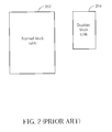
- FIG. 2 is a diagram illustrating a conventional method for managing a memory block.
- the conventional non-volatile memory for example, a flash memory
- the conventional non-volatile memory can be divided into a normal block table 202 and a disabled block table 204 .
- a memory block is placed into the normal block table 202 when the number of error correction bits in the memory block is determined to be lower than a predetermined value. Accordingly, data in the memory blocks in the normal block table 202 of the flash memory can be accessed normally.
- N-Bit ECC the predetermined value
- this memory block is placed into the disabled block table 204 so that data will not be stored into a memory block in the disabled block table 204 . If the disabled block table 204 has no more available space, the flash memory will be locked so that data cannot be written into the flash memory anymore.
- the memory blocks in the normal block table are all usable memory blocks, many usable memory blocks are actually at the edge of being disabled.
- the numbers of error correction bits in some memory blocks may be 3 or exactly 4. Namely, these memory blocks have to be moved from the normal block table 202 to the disabled block table 204 once another 1 or 2 error correction bits occur in these memory blocks.
- the memory blocks at the edge of being disabled are always used for data accessing, these memory blocks will soon be disabled and accordingly the lifespan of the non-volatile memory will be shortened.
- the present invention is directed to a storage apparatus having extended lifespan.
- the present invention is directed to a method for accessing data.
- the method is suitable for a storage apparatus and can extend the lifespan of the storage apparatus.
- the present invention is directed to a method for managing a memory block.
- the method can manage the healthiness of a storage apparatus effectively so as to extend the lifespan thereof.
- the present invention provides a storage apparatus including an interface unit, an access control unit, and a memory unit.
- the interface unit is coupled to the access control unit, and the access control unit is coupled to the memory unit.
- the access control unit receives data through the interface unit and stores the data into the memory unit, or the access control unit reads data from the memory unit and sends the data to a data transmission interface through the interface unit for transmission.
- the memory unit includes a plurality of memory blocks and a plurality of block tables. Each of the memory blocks has n error correction bits, wherein n is a positive integer greater than or equal to 1.
- the block tables respectively have different storing priorities.
- the access control unit can store data into the memory blocks of each block table according to the storing priority of the block table.
- the present invention provides a method for reading data that capable of reading data from above storage apparatus.
- data is read from a memory block in the storage apparatus, and whether the memory block being read has error bits is checked. If the memory block has error bits, the error bits are corrected and detected as error correction bits.
- the block table in which the memory block is placed is determined according to the number of error correction bits in the memory block so that the memory blocks in each block table have the same number of error correction bits.
- the block tables respectively have different storing priorities, and the less error correction bits a memory block has, the higher storing priority of the block table has in which the memory block is placed.
- the present invention provides a method for storing data.
- a plurality of block tables respectively having different storing priorities is provided.
- a plurality of memory blocks is provided, and these memory blocks can be respectively placed into the block tables.
- each of the memory blocks has n error correction bits, wherein n is a positive integer greater than or equal to 1. Those memory blocks having the same number of error correction bits can be placed into the same block table.
- data can be stored into the memory blocks of each block table according to the storing priority of the block table.
- the present invention provides a data accessing method for a storage apparatus.
- a plurality of block tables having different storing priorities is provided, and a plurality of memory blocks respectively having n error correction bits is provided, wherein n is a positive integer greater than or equal to 1.
- n is a positive integer greater than or equal to 1.
- the present invention provides a method for managing a memory block.
- a plurality of block tables having different storing priorities is provided.
- the number of error correction bits in the memory block is checked.
- the memory block is placed into one of the block tables according to the number of error correction bits in the memory block, so that the sequence in which the memory block is used for storing data can be determined.
- the block tables include a plurality of normal block tables and a disabled block tables.
- the memory block When the number of error correction bits in a memory block is not greater than a predetermined value, the memory block is placed into one of the normal block tables. On the other hand, when the number of error correction bits in a memory block is greater than the predetermined value, the memory block is placed into the disabled block table so that it will not be used for storing data.
- those memory blocks having the same number of error correction bits are placed into the same block table so that the healthiness of a storage apparatus can be effectively managed.
- data is stored into memory blocks in each block table according to the storing priority of the block table, so that the lifespan of the storage apparatus can be effectively extended.
- FIG. 1 is a diagram of a non-volatile memory structure.
- FIG. 2 is a diagram illustrating a conventional method for managing a memory block.
- FIG. 3 is a block diagram of a storage apparatus according to an embodiment of the present invention.
- FIG. 4 is a flowchart illustrating a method for reading data according to an embodiment of the present invention.
- FIG. 5 is a flowchart illustrating a method for storing data according to an embodiment of the present invention.
- FIG. 6 is a flowchart illustrating a method for managing a memory block according to an embodiment of the present invention.
- FIG. 3 is a block diagram of a storage apparatus according to an embodiment of the present invention.
- the storage apparatus 300 includes an interface unit 302 , an access control unit 304 , and a memory unit 306 .
- the interface unit 302 is coupled to a data transmission interface 342 and the access control unit 304
- the access control unit 304 is coupled to the memory unit 306 .
- the access control unit 304 stores a data received by the interface unit 302 from the data transmission interface 342 into the memory unit 306 .
- the access control unit 304 reads a data from the memory unit 306 and sends the data to the data transmission interface 342 through the interface unit 302 .
- the data transmission interface 342 may be a wireless or cable transmission interface, such as a universal serial bus (USB).
- USB universal serial bus
- the memory unit 306 may be a flash memory and which has a plurality of block tables, such as block tables 312 , 314 , 316 , 318 , 320 , and 322 .
- the memory unit 306 further has a plurality of memory blocks, such as memory blocks 332 , 334 , 336 , and 338 , and these memory blocks are respectively placed in at least one of the block tables 312 , 314 , 316 , 318 , 320 , and 322 .
- the block tables are categorized into normal block tables 312 , 314 , 316 , 318 , and 320 and a disabled block table 322 .
- the access control unit 304 will not access the memory blocks (for example, the memory blocks 336 and 338 ) in the disabled block table 322 , and the reason for that will be described below.
- the block tables have different storing priorities, for example, the block table 312 has the highest storing priority, the block table 314 has the second highest storing priority, and the block table 320 has the lowest storing priority.
- each of the memory blocks has n error correction bits, wherein n is a positive integer greater than or equal to 1.
- those memory blocks having the same number of error correction bits are placed in the same block table.
- all the memory blocks in the block table 312 have 0 error correction bit.
- all the memory blocks in the block table 312 are normal memory blocks.
- FIG. 4 is a flowchart illustrating a method for reading data according to an embodiment of the present invention.
- the access control unit 304 receives an access command ACC and is about to read a data from the memory unit 306 , the access control unit 304 reads the data from the corresponding memory block, as in step S 402 .
- the access control unit 304 checks whether the memory block has error bits.
- step S 406 the access control unit 304 keeps the memory block in the current block table after it reads the data if the access control unit 304 determines that the memory block does not contain any error bit (as “no” in step S 404 ).
- step S 408 the access control unit 304 corrects the error bits and detects them as error correction bits when the access control unit 304 determines that there are error bits in the memory block (as “yes” in step S 404 ).
- step S 410 the access control unit 304 determines whether the number of error correction bits in the memory block exceeds a predetermined value.
- the predetermined value may be 4.
- the access control unit 304 executes step S 412 to move the memory block to the disabled block table 322 , so that the access control unit 304 does not use the memory block in the disabled block table 322 for storing data when next time a data is stored.
- the access control unit 304 moves the memory block to the corresponding normal block table according to the number of error correction bits in the memory block, as in step S 414 .
- the access control unit 304 determines that a 1 bit program code is erroneous when the access control unit 304 reads a data in the memory block 332 in the block table 312 .
- the access control unit 304 corrects the error bit in the memory block 332 and then detects the error corrected bit as an error correction bit, as in step 408 .
- step S 414 since there is only 1 error correction bit in the memory block 332 , the access control unit 304 moves the memory block 332 from the block table 312 to a normal block table or keeps the memory block 332 in the current block table, such as the block table 314 .
- FIG. 5 is a flowchart illustrating a method for storing data according to an embodiment of the present invention.
- the interface unit 302 when the interface unit 302 receives a data from the data transmission interface 342 and is about to store the data into the storage apparatus 300 , the interface unit 302 sends the received data to the access control unit 304 first.
- a data transmission path is pointed to the block table having the highest storing priority, for example, the block table 312 , by the access control unit 304 according to an access command ACC.
- the memory block placed in the block table 312 for example, the memory blocks 332 and 334 , may be complete memory blocks without any error correction bit. Thus, data access can be carried out to these memory blocks frequently.
- the access control unit 304 checks whether or not the block table to which the data transmission path is currently pointed has available storage space for storing data, as in step S 504 .
- the data transmission path is pointed to the block table having the highest storing priority, namely, the block table 312 .
- the access control unit 304 checks whether the memory blocks in the block table 312 has extra storage space for storing data. Assuming that there is still extra storage space in the block table 312 for storing data (as “yes” in step S 504 ), the access control unit 304 executes step S 506 to store the data into the block table to which the data transmission path is currently pointed (i.e. the block table 312 ).
- step S 508 to check whether the block table to which the data transmission path is currently pointed has the lowest storing priority. Since the data transmission path is currently pointed to the block table 312 and the block table 312 does not have the lowest storing priority (as “no” in step S 508 ), the access control unit 304 points the data transmission path to the block table having the next storing priority, as in step S 510 .
- the access control unit 304 points the data transmission path to the block table 314 and then repeats steps S 504 etc until a block table having extra storage space for storing data is found.
- the block table 320 is the block table having the lowest storing priority in the memory unit 306 . If the access control unit 304 sequentially points the data transmission path from the block table 312 to the block table 320 and none of these block tables has extra storage space, and while executing step S 508 , the access control unit 304 determines that the block table 320 is the block table having the lowest storing priority which also has no extra storage space for storing data, the access control unit 304 can directly execute step S 512 , namely, give up storing the data since the block table 322 is a disabled block table and accordingly the memory blocks placed therein are not used for storing data.
- FIG. 6 is a flowchart illustrating a method for managing a memory block according to an embodiment of the present invention, wherein the method is suitable for a storage apparatus.
- a plurality of block tables having different storing priorities is provided, as in step S 602 .
- these block tables include one or multiple normal block tables and a disabled block table, wherein the functions of these tables have been described above therefore will not be described herein.
- step S 604 the number of error correction bits in the memory block in one or plural normal block tables are checked.
- a block table can be selected for placing a memory block according to the number of error correction bits in the memory block being checked, as in step S 606 .
- Step S 606 will be described in detail herein.
- step S 608 whether the number of error correction bits in the memory block exceeds a predetermined value is determined, as in step S 608 . If the number of error correction bits in the memory block does not exceed the predetermined value (as “no” in step S 608 ), which means the memory block being checked is normal or usable, a normal block table is selected for placing the memory block according to the number of error correction bits in the memory block, as in step S 610 .
- step S 608 if it is determined that the number of error correction bits in the memory block being checked exceeds the predetermined value (as “yes” in step S 608 ), which means the memory block cannot be used for storing data anymore thus the memory block is placed in the disabled block table, as in step S 612 , the memory block will be placed in the disabled block table to avoid storing data in this memory block.
- the disabled block table has no more space, meaning that the storage apparatus is not usable anymore as the number of error correction bits being in a memory block which is exceeding the predetermined value and needs to be placed into the disabled block table, and the storage apparatus is locked so that the storage apparatus is not used for storing data anymore.
- a suitable block table is selected for placing a memory block according to the number of error correction bits in the memory block.
Abstract
A method for managing a memory block is provided. In this method, a plurality of block tables having different storing priorities is provided. In addition, the number of error correction bits in the memory block is checked. Thereby, in the present invention, data is stored into the memory block in a block table according to the number of error correction bits in the memory block so that the sequence in which the memory block is used for storing data is determined.
Description
This is a division of U.S. application Ser. No. 12/022,112, filed on Jan. 29, 2008, and U.S. Pat. No. 8,176,382 has been issued for U.S. application Ser. No. 12/022,112 on May 8, 2012.
1. Technical Field
The present invention generally relates to a technique for accessing data and managing memory blocks, in particular, to a technique for accessing data and managing memory blocks which can extend the lifespan of a storage apparatus.
2. Description of the Conventional Art
On the other hand, if the number of error correction bits in a memory block is determined to be higher than the predetermined value (N-Bit ECC), for example, higher than 4, data error may occur when data is stored in the memory block. Thus, conventionally, this memory block is placed into the disabled block table 204 so that data will not be stored into a memory block in the disabled block table 204. If the disabled block table 204 has no more available space, the flash memory will be locked so that data cannot be written into the flash memory anymore.
Even though the memory blocks in the normal block table are all usable memory blocks, many usable memory blocks are actually at the edge of being disabled. For example, assuming the above predetermined value is 4, the numbers of error correction bits in some memory blocks may be 3 or exactly 4. Namely, these memory blocks have to be moved from the normal block table 202 to the disabled block table 204 once another 1 or 2 error correction bits occur in these memory blocks. However, conventionally, how many error correction bits a memory block of a non-volatile memory has is not taken into consideration when data is stored into the memory block. Thus, if those memory blocks at the edge of being disabled are always used for data accessing, these memory blocks will soon be disabled and accordingly the lifespan of the non-volatile memory will be shortened.
Accordingly, the present invention is directed to a storage apparatus having extended lifespan.
The present invention is directed to a method for accessing data. The method is suitable for a storage apparatus and can extend the lifespan of the storage apparatus.
The present invention is directed to a method for managing a memory block. The method can manage the healthiness of a storage apparatus effectively so as to extend the lifespan thereof.
The present invention provides a storage apparatus including an interface unit, an access control unit, and a memory unit. The interface unit is coupled to the access control unit, and the access control unit is coupled to the memory unit. The access control unit receives data through the interface unit and stores the data into the memory unit, or the access control unit reads data from the memory unit and sends the data to a data transmission interface through the interface unit for transmission. The memory unit includes a plurality of memory blocks and a plurality of block tables. Each of the memory blocks has n error correction bits, wherein n is a positive integer greater than or equal to 1. In addition, the block tables respectively have different storing priorities. Those memory blocks having the same number of error correction bits are placed into the same block table, and the less error correction bits a memory block has, the higher storing priority the block table has in which the memory block is placed. Thus, the access control unit can store data into the memory blocks of each block table according to the storing priority of the block table.
The present invention provides a method for reading data that capable of reading data from above storage apparatus. In this method, data is read from a memory block in the storage apparatus, and whether the memory block being read has error bits is checked. If the memory block has error bits, the error bits are corrected and detected as error correction bits. In addition, the block table in which the memory block is placed is determined according to the number of error correction bits in the memory block so that the memory blocks in each block table have the same number of error correction bits. The block tables respectively have different storing priorities, and the less error correction bits a memory block has, the higher storing priority of the block table has in which the memory block is placed.
The present invention provides a method for storing data. In this method, a plurality of block tables respectively having different storing priorities is provided. Besides, a plurality of memory blocks is provided, and these memory blocks can be respectively placed into the block tables. In addition, each of the memory blocks has n error correction bits, wherein n is a positive integer greater than or equal to 1. Those memory blocks having the same number of error correction bits can be placed into the same block table. Thus, data can be stored into the memory blocks of each block table according to the storing priority of the block table.
The present invention provides a data accessing method for a storage apparatus. In this method, a plurality of block tables having different storing priorities is provided, and a plurality of memory blocks respectively having n error correction bits is provided, wherein n is a positive integer greater than or equal to 1. While reading data from a memory block, in which block table the memory block is placed can be determined according to the number of error correction bits in the memory block, so that the memory blocks in each block table have the same number of error correction bits. In addition, the less error correction bits a memory block has, the higher storing priority the block table has in which the memory block is placed. Moreover, while storing data into the storage apparatus, the data can be stored in the memory blocks of each block table according to the storing priority of the block table.
The present invention provides a method for managing a memory block. In this method, a plurality of block tables having different storing priorities is provided. In addition, the number of error correction bits in the memory block is checked. The memory block is placed into one of the block tables according to the number of error correction bits in the memory block, so that the sequence in which the memory block is used for storing data can be determined.
According to an embodiment of the present invention, the block tables include a plurality of normal block tables and a disabled block tables. When the number of error correction bits in a memory block is not greater than a predetermined value, the memory block is placed into one of the normal block tables. On the other hand, when the number of error correction bits in a memory block is greater than the predetermined value, the memory block is placed into the disabled block table so that it will not be used for storing data.
In the present invention, those memory blocks having the same number of error correction bits are placed into the same block table so that the healthiness of a storage apparatus can be effectively managed. Moreover, in the present invention, data is stored into memory blocks in each block table according to the storing priority of the block table, so that the lifespan of the storage apparatus can be effectively extended.
These and other objectives of the present invention will no doubt become obvious to those of ordinary skill in the art after reading the following detailed description of the preferred embodiment that is illustrated in the various figures and drawings.
The accompanying drawings are included to provide a further understanding of the invention, and are incorporated in and constitute a part of this specification. The drawings illustrate embodiments of the invention and, together with the description, serve to explain the principles of the invention.
Reference will now be made in detail to the present preferred embodiments of the invention, examples of which are illustrated in the accompanying drawings. Wherever possible, the same reference numbers are used in the drawings and the description to refer to the same or like parts.
The memory unit 306 may be a flash memory and which has a plurality of block tables, such as block tables 312, 314, 316, 318, 320, and 322. In addition, the memory unit 306 further has a plurality of memory blocks, such as memory blocks 332, 334, 336, and 338, and these memory blocks are respectively placed in at least one of the block tables 312, 314, 316, 318, 320, and 322. In the present embodiment, the block tables are categorized into normal block tables 312, 314, 316, 318, and 320 and a disabled block table 322. The access control unit 304 will not access the memory blocks (for example, the memory blocks 336 and 338) in the disabled block table 322, and the reason for that will be described below.
Particularly, the block tables have different storing priorities, for example, the block table 312 has the highest storing priority, the block table 314 has the second highest storing priority, and the block table 320 has the lowest storing priority. In addition, each of the memory blocks has n error correction bits, wherein n is a positive integer greater than or equal to 1. In the present embodiment, those memory blocks having the same number of error correction bits are placed in the same block table. For example, all the memory blocks in the block table 312 have 0 error correction bit. In other words, all the memory blocks in the block table 312 are normal memory blocks.
Additionally, the less error correction bits a memory block has, the higher storing priority the block table has in which the memory block is placed. For example, a memory block having no error correction bit is placed in the block table 312, and a memory block having only one error correction bit is placed in the block table 314, and so on.
In step S406, the access control unit 304 keeps the memory block in the current block table after it reads the data if the access control unit 304 determines that the memory block does not contain any error bit (as “no” in step S404). On the other hand, in step S408, the access control unit 304 corrects the error bits and detects them as error correction bits when the access control unit 304 determines that there are error bits in the memory block (as “yes” in step S404).
In step S410, the access control unit 304 determines whether the number of error correction bits in the memory block exceeds a predetermined value. In the present embodiment, the predetermined value may be 4. When the access control unit 304 determines that the number of error correction bits in the memory block is greater than the predetermined value (as “yes” in step S410), which means data stored in this memory block has non-recoverable bit error, the access control unit 304 executes step S412 to move the memory block to the disabled block table 322, so that the access control unit 304 does not use the memory block in the disabled block table 322 for storing data when next time a data is stored.
Contrarily, if the number of error correction bits in the memory block does not exceeds the predetermined value (as “no” in step S410), the access control unit 304 moves the memory block to the corresponding normal block table according to the number of error correction bits in the memory block, as in step S414. For example, the access control unit 304 determines that a 1 bit program code is erroneous when the access control unit 304 reads a data in the memory block 332 in the block table 312. Here, the access control unit 304 corrects the error bit in the memory block 332 and then detects the error corrected bit as an error correction bit, as in step 408. In step S414, since there is only 1 error correction bit in the memory block 332, the access control unit 304 moves the memory block 332 from the block table 312 to a normal block table or keeps the memory block 332 in the current block table, such as the block table 314.
Additionally, the access control unit 304 checks whether or not the block table to which the data transmission path is currently pointed has available storage space for storing data, as in step S504. Presently, the data transmission path is pointed to the block table having the highest storing priority, namely, the block table 312. Thus, the access control unit 304 checks whether the memory blocks in the block table 312 has extra storage space for storing data. Assuming that there is still extra storage space in the block table 312 for storing data (as “yes” in step S504), the access control unit 304 executes step S506 to store the data into the block table to which the data transmission path is currently pointed (i.e. the block table 312).
Contrarily, if the access control unit 304 determines that the block table 312 has no more extra storage space, the access control unit 304 executes step S508 to check whether the block table to which the data transmission path is currently pointed has the lowest storing priority. Since the data transmission path is currently pointed to the block table 312 and the block table 312 does not have the lowest storing priority (as “no” in step S508), the access control unit 304 points the data transmission path to the block table having the next storing priority, as in step S510.
Here it is assumed that the storing priority of the block table 314 is next to that of the block table 312, and all the memory blocks placed in the block table 314 have only 1 error correction bit. When the block table 312 does not have extra storage space for storing data, the access control unit 304 points the data transmission path to the block table 314 and then repeats steps S504 etc until a block table having extra storage space for storing data is found.
Here it is assumed that the block table 320 is the block table having the lowest storing priority in the memory unit 306. If the access control unit 304 sequentially points the data transmission path from the block table 312 to the block table 320 and none of these block tables has extra storage space, and while executing step S508, the access control unit 304 determines that the block table 320 is the block table having the lowest storing priority which also has no extra storage space for storing data, the access control unit 304 can directly execute step S512, namely, give up storing the data since the block table 322 is a disabled block table and accordingly the memory blocks placed therein are not used for storing data.
Step S606 will be described in detail herein. In the present embodiment, after the step S604 is executed, whether the number of error correction bits in the memory block exceeds a predetermined value is determined, as in step S608. If the number of error correction bits in the memory block does not exceed the predetermined value (as “no” in step S608), which means the memory block being checked is normal or usable, a normal block table is selected for placing the memory block according to the number of error correction bits in the memory block, as in step S610.
On the other hand, if it is determined that the number of error correction bits in the memory block being checked exceeds the predetermined value (as “yes” in step S608), which means the memory block cannot be used for storing data anymore thus the memory block is placed in the disabled block table, as in step S612, the memory block will be placed in the disabled block table to avoid storing data in this memory block. In some other embodiments of the present invention, when the disabled block table has no more space, meaning that the storage apparatus is not usable anymore as the number of error correction bits being in a memory block which is exceeding the predetermined value and needs to be placed into the disabled block table, and the storage apparatus is locked so that the storage apparatus is not used for storing data anymore.
In summary, according to the present invention, a suitable block table is selected for placing a memory block according to the number of error correction bits in the memory block. Thereby, in the present invention, access to memory blocks at the edge of being disabled is reduced and the lifespan of the storage apparatus is extended. Moreover, since those memory blocks having the same number of error correction bits are placed in the same block table, the user can monitor the healthiness of the storage apparatus efficiently.
Those skilled in the art will readily observe that numerous modifications and alterations of the device and method may be made while retaining the teachings of the invention. Accordingly, the above disclosure should be construed as limited only by the metes and bounds of the appended claims.
Claims (16)
1. A storage apparatus, comprising:
an interface unit, for transmitting data through a data transmission interface;
an access control unit, coupled to the interface unit for accessing data; and
a memory unit, coupled to the access control unit comprising:
a plurality of memory blocks, for storing data, wherein each of the memory blocks has n error correction bits, wherein n is a positive integer greater than or equal to 1; and
a plurality of block tables, having different storing priorities, wherein memory blocks having the same number of error correction bits are placed into the same block table, and the less error correction bits a memory block has, the higher storing priority the block table has in which the memory block is placed,
wherein the access control unit stores data into the memory blocks in each of the block tables according to the storing priority of the block table.
2. The storage apparatus according to claim 1 , wherein the block table for storing memory blocks having less error correction bits has higher priority so that the access control unit stores data into the block table having higher priority first.
3. The storage apparatus according to claim 1 , wherein when the access control unit stores data, the block tables comprise:
a plurality of normal block tables, wherein the numbers of error correction bits in the memory blocks in each of the normal block tables are not greater than a predetermined value; and
a disabled block table, wherein the numbers of error correction bits in the memory blocks in the disabled block table are greater than the predetermined value so that the access control unit does not store data into the memory blocks in the disabled block table.
4. The storage apparatus according to claim 1 , wherein the memory unit is a non-volatile memory.
5. The storage apparatus according to claim 4 , wherein the non-volatile memory is a flash memory.
6. The storage apparatus according to claim 1 , wherein the data transmission interface is a wireless transmission interface or a cable transmission interface.
7. The storage apparatus according to claim 6 , wherein the cable transmission interface is a Universal Serial Bus (USB).
8. The storage apparatus according to claim 3 , wherein the predetermined value is at least greater than or equal to 4.
9. A data storing method, suitable for a storage apparatus, the data storing method comprising:
providing a plurality of block tables having different storing priorities;
providing a plurality of memory blocks respectively placed in at least one of the block tables, the memory blocks respectively having n error correction bits, wherein n is a positive integer greater than or equal to 1, the memory blocks having the same number of error correction bits being placed in the same block table; and
storing data into the memory blocks in the block tables according to the storing priorities of the block tables.
10. The data storing method according to claim 9 , wherein the block tables comprise:
a plurality of normal block tables, wherein the numbers of error correction bits in the memory blocks in each of the normal block tables are not greater than a predetermined value; and
a disabled block table, wherein the numbers of error correction bits in the memory blocks in the disabled block table are greater than the predetermined value, so that data is not stored in the memory blocks in the disabled block table.
11. The data storing method according to claim 10 , wherein the step of sequentially storing data into the normal block tables comprises:
pointing a data transmission path to the block table having the highest storing priority;
detecting whether the block table to which the data transmission path is currently pointed to has extra storage space;
storing the data into the block table to which the data transmission path is currently pointed to when the block table has extra storage space;
detecting whether the block table to which the data transmission path is currently pointed to has the lowest storing priority when the block table has no extra storage space;
determining that the storage apparatus has no more storage space and giving up storing the data when the block table to which the data transmission path is currently pointed to has the lowest storing priority; and
pointing the data transmission path to the block table having a next storing priority for storing data when the block table to which the data transmission path is currently pointed does not have the lowest storing priority.
12. The data storing method according to claim 9 , wherein the storage apparatus is a non-volatile memory storage apparatus.
13. A data accessing method for a storage apparatus, comprising:
providing a plurality of block tables having different storing priorities;
providing a plurality of memory blocks respectively having n error correction bits, wherein n is a positive integer greater than or equal to 1;
while reading data from one of the memory blocks, determining the block table in which the memory block is placed according to the number of error correction bits in the memory block, so that the memory blocks in each of the block tables have the same number of error correction bits, and the less error correction bits a memory block has, the higher storing priority the block table has in which the memory block is placed; and
while storing data into the storage apparatus, sequentially storing the data into the memory blocks in the block tables according to the storing priorities of the block tables.
14. The data accessing method according to claim 13 , wherein the block tables comprise a plurality of normal block tables and a disabled block table.
15. The data accessing method according to claim 14 , wherein the step of determining the block table in which each of the memory blocks is placed further comprises:
determining whether the number of error correction bits in the memory block is greater than a predetermined value;
when the number of error correction bits in the memory block is not greater than the predetermined value, moving the memory block from a current block table to another normal block table; and
when the number of error correction bits in the memory block is greater than the predetermined value, moving the memory block to the disabled block table so that data is not stored into the memory blocks in the disabled block table.
16. The data accessing method according to claim 13 , wherein the storage apparatus is a non-volatile memory storage apparatus.
Priority Applications (1)
| Application Number | Priority Date | Filing Date | Title |
|---|---|---|---|
| US13/437,936 US8327227B2 (en) | 2007-11-09 | 2012-04-03 | Storage apparatus, method for accessing data and for managing memory block |
Applications Claiming Priority (5)
| Application Number | Priority Date | Filing Date | Title |
|---|---|---|---|
| TW096142491A TWI362044B (en) | 2007-11-09 | 2007-11-09 | Storage apparatus and method for accessing data and for managing memory block |
| TW096142491 | 2007-11-09 | ||
| TW96142491A | 2007-11-09 | ||
| US12/022,112 US8176382B2 (en) | 2007-11-09 | 2008-01-29 | Storage apparatus, method for accessing data and for managing memory block |
| US13/437,936 US8327227B2 (en) | 2007-11-09 | 2012-04-03 | Storage apparatus, method for accessing data and for managing memory block |
Related Parent Applications (1)
| Application Number | Title | Priority Date | Filing Date |
|---|---|---|---|
| US12/022,112 Division US8176382B2 (en) | 2007-11-09 | 2008-01-29 | Storage apparatus, method for accessing data and for managing memory block |
Publications (2)
| Publication Number | Publication Date |
|---|---|
| US20120192033A1 US20120192033A1 (en) | 2012-07-26 |
| US8327227B2 true US8327227B2 (en) | 2012-12-04 |
Family
ID=40624879
Family Applications (3)
| Application Number | Title | Priority Date | Filing Date |
|---|---|---|---|
| US12/022,112 Active 2031-03-10 US8176382B2 (en) | 2007-11-09 | 2008-01-29 | Storage apparatus, method for accessing data and for managing memory block |
| US12/265,417 Active 2030-11-27 US8200919B2 (en) | 2007-11-09 | 2008-11-05 | Storage device with self-condition inspection and inspection method thereof |
| US13/437,936 Active US8327227B2 (en) | 2007-11-09 | 2012-04-03 | Storage apparatus, method for accessing data and for managing memory block |
Family Applications Before (2)
| Application Number | Title | Priority Date | Filing Date |
|---|---|---|---|
| US12/022,112 Active 2031-03-10 US8176382B2 (en) | 2007-11-09 | 2008-01-29 | Storage apparatus, method for accessing data and for managing memory block |
| US12/265,417 Active 2030-11-27 US8200919B2 (en) | 2007-11-09 | 2008-11-05 | Storage device with self-condition inspection and inspection method thereof |
Country Status (2)
| Country | Link |
|---|---|
| US (3) | US8176382B2 (en) |
| TW (1) | TWI362044B (en) |
Cited By (1)
| Publication number | Priority date | Publication date | Assignee | Title |
|---|---|---|---|---|
| US11182310B2 (en) * | 2019-12-24 | 2021-11-23 | SK Hynix Inc. | Priority determination circuit and method of operating the priority determination circuit for preventing overlapping operation |
Families Citing this family (2)
| Publication number | Priority date | Publication date | Assignee | Title |
|---|---|---|---|---|
| US9311176B1 (en) * | 2012-11-20 | 2016-04-12 | Emc Corporation | Evaluating a set of storage devices and providing recommended activities |
| US9514837B2 (en) * | 2015-01-20 | 2016-12-06 | Sandisk Technologies Llc | Selective online burn-in with adaptive and delayed verification methods for memory |
Citations (13)
| Publication number | Priority date | Publication date | Assignee | Title |
|---|---|---|---|---|
| US5559956A (en) * | 1992-01-10 | 1996-09-24 | Kabushiki Kaisha Toshiba | Storage system with a flash memory module |
| US5603001A (en) * | 1994-05-09 | 1997-02-11 | Kabushiki Kaisha Toshiba | Semiconductor disk system having a plurality of flash memories |
| US5617530A (en) * | 1991-01-04 | 1997-04-01 | Emc Corporation | Storage device array architecture with copyback cache |
| US5661848A (en) * | 1994-09-08 | 1997-08-26 | Western Digital Corp | Multi-drive controller with encoder circuitry that generates ECC check bytes using the finite field for optical data for appending to data flowing to HDA |
| US6000006A (en) | 1997-08-25 | 1999-12-07 | Bit Microsystems, Inc. | Unified re-map and cache-index table with dual write-counters for wear-leveling of non-volatile flash RAM mass storage |
| US20030041298A1 (en) | 2001-08-23 | 2003-02-27 | Seagate Technology Llc | Emulation system for evaluating digital data channel configurations |
| US20030058762A1 (en) | 2001-09-26 | 2003-03-27 | Schultz Mark Alan | Defect detection of recordable storage media |
| US20030135793A1 (en) | 2002-01-16 | 2003-07-17 | Sandisk Corporation | Method and apparatus for dynamic degradation detection |
| US6725343B2 (en) * | 2000-10-05 | 2004-04-20 | Hewlett-Packard Development Company, L.P. | System and method for generating cache coherence directory entries and error correction codes in a multiprocessor system |
| US6823429B1 (en) * | 1997-07-10 | 2004-11-23 | International Business Machines Corporation | Memory controller for controlling memory accesses across networks in distributed shared memory processing systems |
| US20070198786A1 (en) | 2006-02-10 | 2007-08-23 | Sandisk Il Ltd. | Method for estimating and reporting the life expectancy of flash-disk memory |
| US20080072118A1 (en) | 2006-08-31 | 2008-03-20 | Brown David A | Yield-Enhancing Device Failure Analysis |
| US20090077429A1 (en) | 2007-09-13 | 2009-03-19 | Samsung Electronics Co., Ltd. | Memory system and wear-leveling method thereof |
Family Cites Families (11)
| Publication number | Priority date | Publication date | Assignee | Title |
|---|---|---|---|---|
| US4819231A (en) * | 1983-01-20 | 1989-04-04 | Nippon Hoso Kyokai | Framing timing detection circuit for a character code broadcasting system |
| US5740349A (en) * | 1993-02-19 | 1998-04-14 | Intel Corporation | Method and apparatus for reliably storing defect information in flash disk memories |
| US6078946A (en) * | 1996-09-10 | 2000-06-20 | First World Communications, Inc. | System and method for management of connection oriented networks |
| KR100205006B1 (en) | 1996-10-08 | 1999-06-15 | 윤종용 | Semiconductor memory device having an automatic falut block mapping function |
| CA2209238C (en) * | 1997-06-27 | 2000-07-25 | Bell Canada | Method and apparatus for monitoring selected telecommunications sessions in an intelligent switched telephone network |
| US6035432A (en) * | 1997-07-31 | 2000-03-07 | Micron Electronics, Inc. | System for remapping defective memory bit sets |
| US5974564A (en) * | 1997-07-31 | 1999-10-26 | Micron Electronics, Inc. | Method for remapping defective memory bit sets to non-defective memory bit sets |
| KR100319893B1 (en) | 1999-07-01 | 2002-01-10 | 윤종용 | Semiconductor memory device capable of easily distinguishing location of defective memory cell by testing selectively block redundancy memory cell block |
| JP4059472B2 (en) * | 2001-08-09 | 2008-03-12 | 株式会社ルネサステクノロジ | Memory card and memory controller |
| US7171594B2 (en) * | 2002-03-06 | 2007-01-30 | Hewlett-Packard Development Company, L.P. | Pausing a transfer of data |
| US7647545B2 (en) * | 2006-02-06 | 2010-01-12 | Radio Systems Corporation | Signal and protocol for remote dog trainer signaling with a forward error correction |
-
2007
- 2007-11-09 TW TW096142491A patent/TWI362044B/en active
-
2008
- 2008-01-29 US US12/022,112 patent/US8176382B2/en active Active
- 2008-11-05 US US12/265,417 patent/US8200919B2/en active Active
-
2012
- 2012-04-03 US US13/437,936 patent/US8327227B2/en active Active
Patent Citations (15)
| Publication number | Priority date | Publication date | Assignee | Title |
|---|---|---|---|---|
| US5617530A (en) * | 1991-01-04 | 1997-04-01 | Emc Corporation | Storage device array architecture with copyback cache |
| US5911779A (en) * | 1991-01-04 | 1999-06-15 | Emc Corporation | Storage device array architecture with copyback cache |
| US5673383A (en) * | 1992-01-10 | 1997-09-30 | Kabushiki Kaisha Toshiba | Storage system with a flash memory module |
| US5559956A (en) * | 1992-01-10 | 1996-09-24 | Kabushiki Kaisha Toshiba | Storage system with a flash memory module |
| US5603001A (en) * | 1994-05-09 | 1997-02-11 | Kabushiki Kaisha Toshiba | Semiconductor disk system having a plurality of flash memories |
| US5661848A (en) * | 1994-09-08 | 1997-08-26 | Western Digital Corp | Multi-drive controller with encoder circuitry that generates ECC check bytes using the finite field for optical data for appending to data flowing to HDA |
| US6823429B1 (en) * | 1997-07-10 | 2004-11-23 | International Business Machines Corporation | Memory controller for controlling memory accesses across networks in distributed shared memory processing systems |
| US6000006A (en) | 1997-08-25 | 1999-12-07 | Bit Microsystems, Inc. | Unified re-map and cache-index table with dual write-counters for wear-leveling of non-volatile flash RAM mass storage |
| US6725343B2 (en) * | 2000-10-05 | 2004-04-20 | Hewlett-Packard Development Company, L.P. | System and method for generating cache coherence directory entries and error correction codes in a multiprocessor system |
| US20030041298A1 (en) | 2001-08-23 | 2003-02-27 | Seagate Technology Llc | Emulation system for evaluating digital data channel configurations |
| US20030058762A1 (en) | 2001-09-26 | 2003-03-27 | Schultz Mark Alan | Defect detection of recordable storage media |
| US20030135793A1 (en) | 2002-01-16 | 2003-07-17 | Sandisk Corporation | Method and apparatus for dynamic degradation detection |
| US20070198786A1 (en) | 2006-02-10 | 2007-08-23 | Sandisk Il Ltd. | Method for estimating and reporting the life expectancy of flash-disk memory |
| US20080072118A1 (en) | 2006-08-31 | 2008-03-20 | Brown David A | Yield-Enhancing Device Failure Analysis |
| US20090077429A1 (en) | 2007-09-13 | 2009-03-19 | Samsung Electronics Co., Ltd. | Memory system and wear-leveling method thereof |
Cited By (1)
| Publication number | Priority date | Publication date | Assignee | Title |
|---|---|---|---|---|
| US11182310B2 (en) * | 2019-12-24 | 2021-11-23 | SK Hynix Inc. | Priority determination circuit and method of operating the priority determination circuit for preventing overlapping operation |
Also Published As
| Publication number | Publication date |
|---|---|
| US8200919B2 (en) | 2012-06-12 |
| TW200921704A (en) | 2009-05-16 |
| US20090125783A1 (en) | 2009-05-14 |
| TWI362044B (en) | 2012-04-11 |
| US8176382B2 (en) | 2012-05-08 |
| US20120192033A1 (en) | 2012-07-26 |
| US20090125759A1 (en) | 2009-05-14 |
Similar Documents
| Publication | Publication Date | Title |
|---|---|---|
| US8713381B2 (en) | Systems and methods of using dynamic data for wear leveling in solid-state devices | |
| US7512864B2 (en) | System and method of accessing non-volatile computer memory | |
| US10379924B2 (en) | Data storage device and data maintenance method thereof | |
| US8671330B2 (en) | Storage device, electronic device, and data error correction method | |
| US8266481B2 (en) | System and method of wear-leveling in flash storage | |
| US8051339B2 (en) | Data preserving method and data accessing method for non-volatile memory | |
| US20160070507A1 (en) | Memory system and method of controlling memory device | |
| US20100287433A1 (en) | Data access apparatus and data access method | |
| JP2011040146A (en) | Bit error threshold and remapping of memory device | |
| KR20050065431A (en) | Information processing apparatus and a rom image generation apparatus for the apparatus | |
| US8316208B2 (en) | Memory controller, flash memory system with memory controller, and method of controlling flash memory | |
| JP7143735B2 (en) | memory controller and memory system | |
| US8327227B2 (en) | Storage apparatus, method for accessing data and for managing memory block | |
| US20170123905A1 (en) | Non-volatile memory device and read method thereof | |
| JP7395388B2 (en) | Memory system and its control method | |
| KR20170086840A (en) | Data storage device and operating method thereof | |
| KR20210079611A (en) | Apparatus and method for improving input/output throughput of memory system | |
| US8006139B2 (en) | Degeneration control device and degeneration control program | |
| KR20210026832A (en) | Apparatus and method for improving input/output throughput of memory system | |
| US11348658B2 (en) | Memory controller and storage device including the same | |
| KR20210083888A (en) | Apparatus and method for improving input/output throughput of memory system | |
| KR20210083941A (en) | Apparatus and method for improving input/output throughput of memory system | |
| US20110040929A1 (en) | Method and apparatus for modifying data sequences stored in memory device | |
| US11004485B2 (en) | Apparatus and method for improving input/output throughput of memory system | |
| US10936248B2 (en) | Data writing method with verifying a part of data, memory controlling circuit unit and memory storage device |
Legal Events
| Date | Code | Title | Description |
|---|---|---|---|
| STCF | Information on status: patent grant |
Free format text: PATENTED CASE |
|
| FPAY | Fee payment |
Year of fee payment: 4 |
|
| MAFP | Maintenance fee payment |
Free format text: PAYMENT OF MAINTENANCE FEE, 8TH YEAR, LARGE ENTITY (ORIGINAL EVENT CODE: M1552); ENTITY STATUS OF PATENT OWNER: LARGE ENTITY Year of fee payment: 8 |
|
| MAFP | Maintenance fee payment |
Free format text: PAYMENT OF MAINTENANCE FEE, 12TH YEAR, LARGE ENTITY (ORIGINAL EVENT CODE: M1553); ENTITY STATUS OF PATENT OWNER: LARGE ENTITY Year of fee payment: 12 |