US8328381B2 - Light for a power tool and method of illuminating a workpiece - Google Patents
Light for a power tool and method of illuminating a workpiece Download PDFInfo
- Publication number
- US8328381B2 US8328381B2 US12/379,585 US37958509A US8328381B2 US 8328381 B2 US8328381 B2 US 8328381B2 US 37958509 A US37958509 A US 37958509A US 8328381 B2 US8328381 B2 US 8328381B2
- Authority
- US
- United States
- Prior art keywords
- pcb
- power tool
- guide
- housing
- collar
- Prior art date
- Legal status (The legal status is an assumption and is not a legal conclusion. Google has not performed a legal analysis and makes no representation as to the accuracy of the status listed.)
- Active, expires
Links
Images


Classifications
-
- B—PERFORMING OPERATIONS; TRANSPORTING
- B25—HAND TOOLS; PORTABLE POWER-DRIVEN TOOLS; MANIPULATORS
- B25F—COMBINATION OR MULTI-PURPOSE TOOLS NOT OTHERWISE PROVIDED FOR; DETAILS OR COMPONENTS OF PORTABLE POWER-DRIVEN TOOLS NOT PARTICULARLY RELATED TO THE OPERATIONS PERFORMED AND NOT OTHERWISE PROVIDED FOR
- B25F5/00—Details or components of portable power-driven tools not particularly related to the operations performed and not otherwise provided for
- B25F5/02—Construction of casings, bodies or handles
- B25F5/021—Construction of casings, bodies or handles with guiding devices
Definitions
- the present application relates generally to handheld power tools. More particularly, the present application relates to handheld power tools having a light configured to shine onto a workpiece machined by the power tool.
- Power tools are often used in a variety of conditions ranging from well-lit indoor work spaces to outside construction sites or other areas that are not always well-lit. Accordingly, it is desirable to provide a method or apparatus that permits a power tool to have a lighting feature that will illuminate the workpiece that is being machined or worked on by the power tool. Such a lighting feature will assist a user to be able to adequately see the workpiece or work area that is being worked on or machined by the power tool even in substandard light conditions.
- an apparatus in some embodiments provides a power tool having lighting features that will illuminate a workpiece being machined by the power tool.
- the lighting feature is protected from the environment in which the power tool operates.
- a power tool in accordance with one embodiment of the present invention, includes a housing, a end effector rotatable with respect to the housing, a collar rotatable with respect to the housing, a printed circuit board (PCB) rotatably fixed with respect to the housing, and a lighting element operatively connected to the PCB and adjacent to the end effector and in a recess of the collar and located to illuminate a workpiece machined by the power tool.
- PCB printed circuit board
- a power tool in accordance with another embodiment of the present invention, includes a rotatable end effector, a rotatable collar, a printed circuit board (PCB), lighting elements operatively connected to the PCB and adjacent to the end effector and located to illuminate a workpiece machined by the power tool, and a guide supporting the PCB and wires configured to provide power to the PCB for illuminating the lighting elements, wherein the PCB and a portion of the guide are generally circular in shape, the lighting elements are annularly arranged on the PCB and portion of the end effector extends through a hole in the defined by the guide and PCB and the guide defines a groove and the PCB is located in the groove.
- PCB printed circuit board
- a method of providing light for a workpiece being machined by a power tool includes locating lighting elements around a spindle of a power tool, aligning the lighting elements to shine light on a workpiece being machined by the power tool, operatively connecting the lighting elements to a PCB, containing and supporting the PCB with a guide, supporting wires configured to provide power to the PCB with the guide, locating the lighting elements, PCB and guide in a rotatable collar, and preventing the lighting elements, PCB and guide from rotating when the collar rotates.
- FIG. 1 is a side view illustrating a power tool in accordance with an embodiment of the invention.
- FIG. 2 is a perspective view illustrating a front portion of a power tool in accordance with an embodiment of the invention.
- FIG. 3 is a perspective close-up view of the power tool of FIG. 2 with the end effector removed in order to more distinctly show surrounding elements.
- FIG. 4 is a perspective view similar to that shown in FIG. 3 with a retaining ring removed in order to more clearly show surrounding elements.
- FIG. 5 is a perspective view of a wire guide and printed circuit board (PCB) having light emitting diode (LED) elements.
- PCB printed circuit board
- FIG. 6 is a partial perspective view of a bottom portion of the wire guide and PCB.
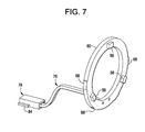
- FIG. 7 is a perspective view of the PCB and wires with the wire guide removed.
- FIG. 8 is a partial perspective rear view of the wire guide, PCB, and wires.
- FIG. 9 is a partial exploded perspective view of the wire guide and a power tool having some elements removed to better show other elements.
- FIG. 10 is a partial perspective view of a wire guide, clutch adjusting nut, clutch spring, and clutch washer mounted on the wire guide.
- FIG. 11 is a partial perspective view of a power tool and clutch collar where the clutch collar is shown in a forward position to illustrate the clutch adjusting nut, clutch spring, and clutch washer mounted to the nose cone.
- FIG. 12 is a partial rear perspective view of the wire guide mounted on the clutch collar.
- FIG. 13 is a partial perspective view of the wire guide mounted onto the nose cone.
- FIG. 14 is a partial cutaway perspective view of a nose cone as well as other elements mounted to the nose cone. The end effector and power transmission elements are removed for clarity.
- FIG. 15 is a perspective rear view of a holder in accordance with another embodiment of the invention.
- FIG. 16 is a partial perspective view of a power tool equipped with a holder similar to that shown in FIG. 15 .
- FIG. 17 is a partial perspective view with part of the housing removed of a power tool equipped with a holder similar to that shown in FIG. 15 .
- FIG. 18 is a partial perspective view of a power tool with part of the housing removed to expose interior components.
- FIG. 19 is a partial perspective cut-away view of a power tool equipped with a holder similar to that shown in FIG. 15 .
- the cut-away view illustrates some of the internal components of the power tool.
- An embodiment in accordance with the present invention provides a power tool having a light ring configured to shine light onto a workpiece being machined by the power tool.
- light emitting elements such as light emitting diodes (LEDs) are placed in an annular or ring shape around part of the end effector and are configured to shine forward to illuminate the tool or accessory held by the end effector and the workpiece being machined by the tool.
- the end effector may be a tool or accessory holder mounted to an output spindle of the tool.
- Examples of end effectors that may be used in accordance with the invention may be the 7000 Series chuck manufactured and marketed by the Jacobs Chuck Manufacturing Company of Clemson, S.C. and quick change chucks similar to that which is found on products such as a DC825KA Impact Driver and a DC815KA Impact Driver that are manufactured and marketed by the DeWalt Industrial Tool Company of Baltimore, Md.
- LED lights are discussed here as an example and do not limit embodiments in accordance with the invention to tools using LEDs.
- the LED lights, or other lighting elements, and associated parts are locked to the housing of the tool and do not rotate when the power tool is operated.
- the lights may be powered by the same power source that provides power to the power tool's motor.
- it is a battery that powers the power tool and in the case of corded tools it is AC current provided from source voltage through a cord. This AC current may be modified according to the needs of the lighting device being employed.
- a rectifier may be employed to convert AC current to DC.
- FIG. 1 shows a power driver 20 .
- the power driver 20 has a housing 22 .
- the housing may be of a clam shell type or any other suitable type housing.
- the power driver 20 may have a nose cone 23 located at the front portion of the power driver 20 .
- a handle 24 projects downwardly from the housing 22 and is terminated with a battery 26 .
- the battery 26 provides the power to turn the end effector 28 .
- the end effector 28 may be configured to hold an accessory or tool such as a drill bit or a driving type accessory such as a Philips or standard screwdriver. Other types of tools or accessories may be held and used in the end effector 28 as can appreciated by one skilled in the art.
- the movement of the end effector 28 may be controlled by the trigger 30 .
- the trigger 30 may selectively provide power from the battery 26 to the motor 32 located within the housing 22 . In some embodiments of the invention, the more the trigger or switch 30 is depressed the more power may be applied to the motor 32 which may cause the end effector 28 to spin faster.
- the power driver 20 may be equipped with a clutch collar 34 .
- Other embodiments in accordance with the invention may not have a rotating clutch collar, but rather a different rotating collar mechanism.
- the rotating collar mechanism may be a drill/hammer mode selector, a gear shifter, an on/off switch, a tool variable speed control or other rotating collar control mechanism.
- this specification will refer to a clutch collar as an example but does not limit embodiments in accordance with the invention to tools having clutch collars.
- the clutch collar 34 can provide protection for interior portions of the power driver 20 , particularly the transmission and other internal components of the power driver 20 that may be mounted on the nose cone 23 .
- the clutch collar 34 may be rotated to adjust the transmission.
- a light ring 38 is located on a front portion of the power tool 20 just behind the end effector 28 in a recess 39 in the clutch collar 34 .
- FIG. 2 a partial perspective view of a front portion of the power driver 20 is shown.
- An indicator 37 may be located on the nose cone 23 .
- the indicator 37 may provide a reference for the user for determining the angular position of the clutch collar 34 and a reference point for comparing the numbers on the numbered scale 36 .
- the light ring 38 is located within a recess 39 of the clutch collar 34 .
- the light ring 38 may include a lens cover 40 .
- the lens cover 40 may protect interior components of the tool from moisture or other contaminants.
- the lens cover 40 may include blisters 42 located on the lens cover 40 as to be directly over the LEDs 58 (as shown in FIG. 5 ).
- the blisters 42 may be translucent or clear in order to permit light generated by the LEDs 58 to pass through.
- the blisters 42 may direct or focus the light.
- the blisters 42 may be round, rectangular, square or any other shape.
- the blisters 42 are shaped to correspond with the shape of the lighting elements 58 .
- the light may simply pass through the blisters 42 .
- the remainder of the lens cover 40 may be a dark color. Other color schemes may be used in accordance with the invention.
- the lens cover 40 is held axially in place from moving in a forward direction toward the end effector 28 by retaining ring 44 .
- the retaining ring 44 is mounted on a retainer 46 which is part of the nose cone 37 as better illustrated in FIGS. 13 and 14 and described in more detail later below.
- FIG. 3 is a similar view to that shown in FIG. 2 , however, the end effector 28 is removed to better illustrate certain features associated with the retaining ring 44 and the retainer 46 .
- FIG. 3 shows portions 48 of the retaining ring 44 exposed in gap 50 that would fit within the groove 52 if it were not in the gap 50 .
- the retaining ring 44 fits within a groove 52 in the retainer 46 . When the retaining ring 44 is placed in the groove 52 the retaining ring 44 is secured in place.
- the retaining ring 44 prevents the lens cover 40 from axially moving forward toward the end effector 28 .
- FIG. 4 is a similar view as that shown in FIG. 3 , however, the retaining ring 44 has been removed as well as the end effector 28 to better illustrate features of the lens cover 40 and the retainer 46 .
- the lens cover 40 includes tabs 56 which are located within the gaps 50 of the retainer 46 .
- the tab 56 and gap 50 combination keep the lens cover 40 aligned and from rotating around the retainer 46 .
- the groove 52 is also illustrated in FIG. 4 in which the retaining ring 44 is located as shown in FIG. 3 .
- FIG. 5 illustrates other aspects of the light ring 38 which are normally contained within the clutch collar 34 and located behind the lens cover 40 .
- light emitting diodes or LEDs 58 are located at various points around the light ring 38 .
- the LEDs 58 emit white light although in other embodiments the LEDs 58 might emit other colors of light.
- different LEDs on the same tool could emit different colors of light. While the embodiment shown in FIG. 5 illustrates three LEDs 58 any number of LEDs may be used in accordance with the invention including one or more.
- the LEDs 58 are mounted to a ring-shaped printed circuit board or PCB 60 .
- the PCB 60 and LEDs 58 are fit into a trench 61 in the wire way 62 .
- the wire way 62 and trench 61 may allow for potting of the PCB if necessary.
- the wire way 62 provides protection and structural strength for the PCB so that undue mechanical loads are not placed upon the PCB 60 . Such support is desirable as a PCB 60 may be fragile and subject to breaking or malfunctioning.
- the wire way 62 may include snap-in features 64 which allow the PCB 60 to be pushed into the wire way 62 and then the snap-in features 64 snap out once the PCB 60 is located within the wire way 62 .
- the snap-in features 64 prevent the PCB 60 from coming out of the wire way 62 .
- the wire way 62 may include grooves 66 .
- Tabs 68 located on the PCB 62 may fit within the grooves 66 within the wire way 62 .
- the tabs 68 and grooves 66 combination help the PCB 60 and the wire way 62 be aligned and may prevent or resist the PCB 60 from rotating with respect to the wire way 62 .
- the wire way 62 may include a PCB holding portion 70 which is generally circular in shape and a wire supporting portion 72 .
- the wire supporting portion 72 may include a channel 74 which is sized and located to contain wires 76 .
- the wires 76 may provide power to the PCB 60 which in turns provides power to illuminate the LEDs 58 .
- the wire supporting portion 72 of the wire way 62 provides a structure for the wires 76 to be supported in and provides protection for the wires 76 .
- the wires 76 may terminate with a plug 78 .
- the plug 78 may fit into plug supporting structure 80 located within the wire supporting portion 72 so that the plug 78 , which is made of a more rigid material than the wires 76 , is held securely to the wire way 62 via the plug supporting structure 80 .
- the plug 78 may be press fit into the wire supporting portion 72 of the wire way 62 .
- the circuit to which the PCB 60 is connected may also include an electromagnetic surge suppression circuit (such as a zener diode) for static and over-voltage protection.
- the circuit may also include a resistor or resistors to drop the voltage from the battery pack voltage to an appropriate level for the LEDs.
- Some embodiments do not have a separate PCB, wire guide, wires and connector.
- plated plastics can be used whereby the wire guide could be first molded into a shape similar to the wire guide 62 as shown.
- tracks like on a standard PCB
- the components could then be soldered to this one piece, and would be electrically connected back to the place where the wires would connect it to the switch. This would greatly simplify the assembly.
- FIG. 6 is a partial perspective view of a bottom portion of the wire way 62 .
- the wire way 62 may be equipped with a collar stopping tab 82 which will be explained in more detail below as FIG. 12 is discussed.
- FIG. 7 is a perspective view similar to that shown in FIG. 5 , however, the wire way 62 has been removed in order to better illustrate some of the features shown in FIG. 7 .
- the LEDs 58 are mounted onto the PCB 60 .
- the PCB 60 shows the tabs 68 . While the embodiments shown in the figures show five tabs 68 , one skilled in the art can appreciate that other numbers of tabs or other features may be employed in order to help keep the PCB aligned and/or rotationally locked to the wire way 68 .
- the wires 76 are attached to a rear portion of the PCB 60 .
- the plug 78 includes the plug stopping structure 84 which butts against a portion of the wire way 68 to prevent the plug 78 from being inserted too far into the wire way 62 .
- FIG. 8 illustrates the plug stopping structure 84 located on the plug 78 butted against the wire supporting portion 72 of the wire way 62 .
- the wires 76 are located within the channel 74 .
- the plug 78 snaps into the wire supporting portion 72 and the wires 76 may be pressed into the channel 74 in a press fit manner to secure the wires 76 into the channel 74 .
- a rear portion of the collar stopping tab 82 is also illustrated in FIG. 8 .
- FIG. 9 illustrates the housing 22 and the wire way 62 .
- the nose cone 23 has been removed in order to better illustrate how the plug 78 attaches to a receiving plug 86 .
- the plug 78 is slid into the receiving plug 76 .
- the plug stopping structure 84 slides into slots 87 located on the receiving plug 86 .
- power from the wires 88 is communicated to the wire 76 .
- the joint made of the plug 78 and the receiving plug 86 provide a rigid support for the connection of the wires 76 and 88 .
- the wires 88 may receive power from the battery 26 as controlled by the trigger 30 .
- the wires 88 extend out of a switch body associated with the trigger 30 .
- a switch body could have connectors to which the wires 88 are soldered or otherwise connected.
- the trigger switch may include electronics for variable speed control.
- the wires 88 may be soldered to a PCB located inside the switch body.
- FIG. 10 is a partial perspective view of the guide 62 showing several additional elements on the guide 62 .
- a clutch adjusting nut 90 is butted against the guide 62 .
- the stop tab 82 is fit into a notch 92 in the clutch adjusting nut 90 .
- the notch 92 in the clutch adjusting nut 90 aligns to the stopping tab 82 on the guide 62 to assist in providing proper assembly of the threads between the adjusting nut 90 and the nose cone 23 during assembly.
- the notch 92 and the clutch adjusting nut 90 may have chamfered edges 96 to the notch walls 94 .
- the chamfered edges 96 may assist in the stopping tab 82 to be seated in the notch 92 and the clutch adjusting nut 90 .
- a combination of the notch 92 and the clutch adjusting nut 70 and the stopping tab 82 in combination with the other tabs and notch combinations 50 , 56 , 66 , 68 can assure that the lens cover 40 , the nose cone 23 , the wire way 62 , the PCB 60 , and the clutch adjusting nut 90 are aligned with respect to each other.
- the clutch adjusting nut 90 includes a ridge 100 .
- a clutch spring 102 urges at one end against the ridge 100 and at the opposite end of the clutch spring 102 , the clutch spring 102 urges against a clutch washer 104 .
- the clutch spring 102 exerts a force on the ridge 100 of the clutch adjusting nut 90 which in turn urges the wire way 62 against the lens cover 40 and ultimately against the retaining ring 44 .
- the force exerted by the clutch spring 102 keeps the light ring assembly 38 in axial position.
- the clutch washer 104 urges against the nose cone 23 .
- FIG. 11 illustrates the clutch washer 104 , clutch spring 102 , and the clutch adjusting nut 90 mounted to the nose cone 23 .
- the clutch collar 34 is shown in a forward axial position and not yet installed on the power tool 20 in order to expose the clutch washer 104 , the clutch spring 102 and the clutch adjusting nut 90 .
- a tab 98 on the clutch adjusting nut 90 is scored with marks or notches 106 on one of the adjustment tabs 98 .
- the scoring 106 provides a visual aid when assembling the collar 34 to properly align the clutch collar 34 .
- the adjustment tab 98 on the clutch adjusting nut 90 is aligned with a desired notch 108 in the clutch collar 34 . Once the desired notch 108 is aligned with the desired adjustment tab 98 , the clutch collar 34 can be fitted onto the power tool 20 .
- the indicator 34 and the numbered scale 36 may also provide assistance in aligning the clutch collar 34 to provide proper assembly of the clutch collar 34 onto the nose cone 23 .
- FIG. 12 is a partial perspective view of the clutch collar 34 installed onto the guide 62 .
- the clutch collar 34 in some embodiments in accordance with the invention, is rotatable.
- the clutch collar 34 is rotatable on the power tool 20 in order to provide different torque and/or speed settings for the end effector 28 . It may be desirable to limit the rotation of the clutch collar 34 in both directions to establish a maximum setting for turning the clutch collar clockwise and a maximum setting when turning the clutch collar counterclockwise as shown in FIG. 12 .
- FIG. 12 also illustrates additional notches 108 in the clutch collar 34 for providing detents when the clutch collar 34 is rotated to various settings with respect to the nose cone 23 .
- FIG. 13 is a partial perspective view of the guide 62 mounted onto a stem portion 120 of the nose cone 23 .
- a lock portion 124 of the guide 62 fits into a groove 122 of the stem portion 120 of the nose cone 23 .
- the groove 122 is sized and dimensioned so that the lock portion 124 of the wire supporting portion 72 of the guide 62 fits within the groove 122 and locks the guide 62 to be angularly fixed with respect to the nose cone 23 .
- the locks 124 located on the wire supporting portion 72 of the guide 62 are wider than the rest of the wire supporting portion 72 and aid in permitting the guide 62 to be securely seated in the groove 122 of the stem portion 120 of the nose cone 23 .
- a second groove 126 is in the nose cone 23 for allowing the wire supporting portion 72 of the guide 62 to fit within the groove 126 of the nose cone 23 .
- the retainer 46 on the nose cone 23 and the groove 52 of the nose cone 23 are also shown forward of the guide 62 . The above described features also help align the guide 62 with respect to the nose cone 23 .
- the retainer 46 is integral with the stem 120 and the nose cone 23 . In other embodiments of the inventions, they may be separable parts.
- FIG. 14 is a partial cutaway perspective view of the nose cone 23 and additional parts described below.
- FIG. 14 shows how the parts described herein are assembled together according to some embodiments of the invention.
- the transmission, spindle, and other parts associated with turning the end effector have been omitted to more clearly show the parts described herein.
- the retaining ring 44 is seated within the groove 52 of the retainer 46 .
- the retaining ring 44 provides a limit of forward axial movement of the lens cover 40 , the guide 62 , and the clutch adjusting nut 90 .
- the clutch spring 102 presses against the clutch washer 104 to urge the clutch adjusting nut 90 to urge the guide 62 , PCB 60 , and lens cover 40 against the retaining ring 44 .
- the wires 76 are located in a channel 74 defined by the guide 62 and the nose cone 23 . The wires 76 are protected from the spinning parts of the end effector mechanism.
- the light ring 38 can be used on other rotary power tools such as impact drivers, drills, hammer drills, routers.
- FIG. 15 illustrates a perspective rear view of a holder 140 that is used on a power tool that is not equipped with a collar as described in the embodiments above.
- the holder 140 holds the light ring 38 .
- the light ring 38 includes the PCB 60 similar to that described above.
- the PCB 60 and the holder 140 may include snap-in features 64 similar to that described above so that the PCB 60 snaps into and is secured in the holder 140 .
- a circular lens cover 40 may be mounted to the holder 140 in front of the PCB 60 similar to embodiments described above.
- the lens cover 40 may include snap-in elements that correspond with snap-in elements on the holder 140 .
- the lens 40 may be secured in place with a retaining ring system similar to that described above.
- the holder 140 may attach to the nose cone 23 with snap-in elements located on both the holder 140 and the nose ring 23 similar to the snap-in features 64 described in the embodiments above.
- the light ring holder 140 may be secured in place in a variety of ways including, but not limited to, a retaining ring system similar to the embodiments described above.
- the holder 140 includes a housing portion 142 , a chin shroud 144 , and a wire way portion 146 .
- Wires 76 connect the PCB 60 (which contains light emitting elements similar to those described above) with a plug 78 .
- the holder 140 does not fully support the wires 76 along the full length of the wires 76 all the way to the plug 78 . Rather, the wire way portion 146 stops at some point along the length of the wires 76 , leaving the wires 76 and the plug 78 to be not supported by the holder 140 .
- FIG. 16 is a partial perspective view of a power tool 147 that does not have a rotatable clutch collar but rather is equipped with the holder 140 .
- the lens cover 40 is shown mounted in a recess in the holder 140 .
- the holder 140 is mounted to the nose cone 23 which is supported by the housing 22 .
- a fastener hole 148 is shown in the housing 22 .
- the fastener hole 148 provides a place for a fastener such as a screw or bolt to connect the two halves of the clam shell type housing 22 together. While the fastener is not shown in FIG.
- a fastener will be located in the fastener hole 148 to connect the two halves of the clam shell housing 22 together.
- Other embodiments of the invention may connect the clamshells of the housing 22 in other ways.
- Some embodiments of the invention may include one piece housings or other types of housings than the clam shell housing shown in FIG. 16 .
- the chin shroud 144 is located on the holder 140 and provides a housing for a portion of the wires 76 so that the wires 76 are not exposed outside of the power tool 147 .
- FIGS. 17 and 18 show the power tool 147 with part of the housing 22 removed.
- the housing 22 is a clam shell type housing and one of the clam shells is removed exposing the clam shell housing 22 located on the far side of the power tool 147 .
- the holder 140 is shown mounted to the nose cone 23 .
- a fastener hole tube 150 located in the fastener hole 148 is shown.
- the wires 76 are routed around the hole tube 150 and are located in the interior 152 of the housing 22 .
- the wires 76 are terminated with a plug 78 also located in the interior 152 of the housing 22 .
- the interior 152 of the housing defines a space or pathway for the wires 76 and the plug 78 .
- the chin shroud 144 defines a wire way portion 146 through which the wires 76 are strung.
- the chin shroud 144 also includes retaining structure 154 which is set in a retaining area 156 defined by the housing 22 .
- FIG. 19 is a partial perspective cut-away view showing the end effector 28 associated with the power tool 147 extending through the lens cover 40 located in front of the PCB 60 .
- LEDs (not shown in FIG. 19 ) are located on the PCB 60 and configured to light the tool or workpiece being worked on by the power tool 147 .
- the wires 76 provide power between the PCB 60 and a power source connected via the plug 78 to power source.
- the wires 76 are located in the wire way portion 146 of the chin shroud 144 and the interior 152 of the housing 22 .
- the chin shroud 144 has the retaining structure 154 located in the retaining area 156 defined by the housing 22 .
Abstract
A power tool including a end effector rotatable with respect to the housing, a collar rotatable with respect to the housing, a printed circuit board (PCB) rotatably fixed with respect to the housing, and a light element operatively connected to the PCB and adjacent to the end effector and in a recess of the collar and located to illuminate a workpiece machined by the power tool. A method of providing light for a workpiece being machined by a power tool including locating lighting elements around a spindle of a power tool, aligning the lighting elements to shine light on a workpiece being machined by the power tool, operatively connecting the lighting elements to a PCB, containing and supporting the PCB with a guide, supporting wires configured to provide power to the PCB with the guide, locating the lighting elements, PCB and guide in a rotatable collar, and preventing the lighting elements, PCB and guide from rotating when the collar rotates.
Description
The present application relates generally to handheld power tools. More particularly, the present application relates to handheld power tools having a light configured to shine onto a workpiece machined by the power tool.
Power tools are often used in a variety of conditions ranging from well-lit indoor work spaces to outside construction sites or other areas that are not always well-lit. Accordingly, it is desirable to provide a method or apparatus that permits a power tool to have a lighting feature that will illuminate the workpiece that is being machined or worked on by the power tool. Such a lighting feature will assist a user to be able to adequately see the workpiece or work area that is being worked on or machined by the power tool even in substandard light conditions.
Because power tools may be used in adverse environmental conditions, it is desirable to protect such a lighting feature from the adverse environmental conditions.
The foregoing needs are met, to a great extent, by the present invention, wherein in one aspect an apparatus is provided that in some embodiments provides a power tool having lighting features that will illuminate a workpiece being machined by the power tool. In some embodiments in accordance with the invention, the lighting feature is protected from the environment in which the power tool operates.
In accordance with one embodiment of the present invention, a power tool is provided. The power tool includes a housing, a end effector rotatable with respect to the housing, a collar rotatable with respect to the housing, a printed circuit board (PCB) rotatably fixed with respect to the housing, and a lighting element operatively connected to the PCB and adjacent to the end effector and in a recess of the collar and located to illuminate a workpiece machined by the power tool.
In accordance with another embodiment of the present invention, a power tool is provided. The power tool includes a rotatable end effector, a rotatable collar, a printed circuit board (PCB), lighting elements operatively connected to the PCB and adjacent to the end effector and located to illuminate a workpiece machined by the power tool, and a guide supporting the PCB and wires configured to provide power to the PCB for illuminating the lighting elements, wherein the PCB and a portion of the guide are generally circular in shape, the lighting elements are annularly arranged on the PCB and portion of the end effector extends through a hole in the defined by the guide and PCB and the guide defines a groove and the PCB is located in the groove.
In accordance with yet another embodiment of the present invention, a method of providing light for a workpiece being machined by a power tool is provided. The method includes locating lighting elements around a spindle of a power tool, aligning the lighting elements to shine light on a workpiece being machined by the power tool, operatively connecting the lighting elements to a PCB, containing and supporting the PCB with a guide, supporting wires configured to provide power to the PCB with the guide, locating the lighting elements, PCB and guide in a rotatable collar, and preventing the lighting elements, PCB and guide from rotating when the collar rotates.
There has thus been outlined, rather broadly, certain embodiments of the invention in order that the detailed description thereof herein may be better understood, and in order that the present contribution to the art may be better appreciated. There are, of course, additional embodiments of the invention that will be described below and which will form the subject matter of the claims appended hereto.
In this respect, before explaining at least one embodiment of the invention in detail, it is to be understood that the invention is not limited in its application to the details of construction and to the arrangements of the components set forth in the following description or illustrated in the drawings. The invention is capable of embodiments in addition to those described and of being practiced and carried out in various ways. Also, it is to be understood that the phraseology and terminology employed herein, as well as the abstract, are for the purpose of description and should not be regarded as limiting.
As such, those skilled in the art will appreciate that the conception upon which this disclosure is based may readily be utilized as a basis for the designing of other structures, methods and systems for carrying out the several purposes of the present invention. It is important, therefore, that the claims be regarded as including such equivalent constructions insofar as they do not depart from the spirit and scope of the present invention.
The invention will now be described with reference to the drawing figures, in which like reference numerals refer to like parts throughout. An embodiment in accordance with the present invention provides a power tool having a light ring configured to shine light onto a workpiece being machined by the power tool.
According to some embodiments of the invention, light emitting elements, such as light emitting diodes (LEDs), are placed in an annular or ring shape around part of the end effector and are configured to shine forward to illuminate the tool or accessory held by the end effector and the workpiece being machined by the tool. The end effector may be a tool or accessory holder mounted to an output spindle of the tool. Examples of end effectors that may be used in accordance with the invention may be the 7000 Series chuck manufactured and marketed by the Jacobs Chuck Manufacturing Company of Clemson, S.C. and quick change chucks similar to that which is found on products such as a DC825KA Impact Driver and a DC815KA Impact Driver that are manufactured and marketed by the DeWalt Industrial Tool Company of Baltimore, Md.
While several different types of lighting elements can be used in accordance with the invention, such as light bulbs (for example, xenon bulbs) or other lighting elements, LED lights are discussed here as an example and do not limit embodiments in accordance with the invention to tools using LEDs. The LED lights, or other lighting elements, and associated parts are locked to the housing of the tool and do not rotate when the power tool is operated. The lights may be powered by the same power source that provides power to the power tool's motor. In the case of most cordless power tools, it is a battery that powers the power tool and in the case of corded tools it is AC current provided from source voltage through a cord. This AC current may be modified according to the needs of the lighting device being employed. In the case of LED lights, a rectifier may be employed to convert AC current to DC.
An embodiment in accordance with the invention is illustrated in FIG. 1 . FIG. 1 shows a power driver 20. The power driver 20 has a housing 22. The housing may be of a clam shell type or any other suitable type housing. The power driver 20 may have a nose cone 23 located at the front portion of the power driver 20. A handle 24 projects downwardly from the housing 22 and is terminated with a battery 26. The battery 26 provides the power to turn the end effector 28.
The end effector 28 may be configured to hold an accessory or tool such as a drill bit or a driving type accessory such as a Philips or standard screwdriver. Other types of tools or accessories may be held and used in the end effector 28 as can appreciated by one skilled in the art. The movement of the end effector 28 may be controlled by the trigger 30. The trigger 30 may selectively provide power from the battery 26 to the motor 32 located within the housing 22. In some embodiments of the invention, the more the trigger or switch 30 is depressed the more power may be applied to the motor 32 which may cause the end effector 28 to spin faster.
The power driver 20 may be equipped with a clutch collar 34. Other embodiments in accordance with the invention may not have a rotating clutch collar, but rather a different rotating collar mechanism. The rotating collar mechanism may be a drill/hammer mode selector, a gear shifter, an on/off switch, a tool variable speed control or other rotating collar control mechanism. However, this specification will refer to a clutch collar as an example but does not limit embodiments in accordance with the invention to tools having clutch collars. The clutch collar 34 can provide protection for interior portions of the power driver 20, particularly the transmission and other internal components of the power driver 20 that may be mounted on the nose cone 23. The clutch collar 34 may be rotated to adjust the transmission. An example of a clutch and transmission that may work in accordance with the invention is shown in U.S. Pat. No. 7,066,691 which is incorporated by reference in its entirety. Of course, most any type of clutch and transmission may be used in accordance with the invention. Different angular positions of the clutch collar 34 may provide different amounts of torque and/or speed to the end effector 28 for a given trigger 30 position. A numbered scale 36 may appear on the clutch collar 34 in order to provide a user an indication of the setting of the clutch collar 34. In some embodiments the user may turn the clutch collar 34 to a desired position by hand.
A light ring 38 is located on a front portion of the power tool 20 just behind the end effector 28 in a recess 39 in the clutch collar 34.
In FIG. 2 , a partial perspective view of a front portion of the power driver 20 is shown. An indicator 37 may be located on the nose cone 23. The indicator 37 may provide a reference for the user for determining the angular position of the clutch collar 34 and a reference point for comparing the numbers on the numbered scale 36. The light ring 38 is located within a recess 39 of the clutch collar 34. The light ring 38 may include a lens cover 40. The lens cover 40 may protect interior components of the tool from moisture or other contaminants. The lens cover 40 may include blisters 42 located on the lens cover 40 as to be directly over the LEDs 58 (as shown in FIG. 5 ). The blisters 42 may be translucent or clear in order to permit light generated by the LEDs 58 to pass through. In some embodiments the blisters 42 may direct or focus the light. The blisters 42 may be round, rectangular, square or any other shape. In some embodiments the blisters 42 are shaped to correspond with the shape of the lighting elements 58. In other embodiments the light may simply pass through the blisters 42. The remainder of the lens cover 40 may be a dark color. Other color schemes may be used in accordance with the invention.
The lens cover 40 is held axially in place from moving in a forward direction toward the end effector 28 by retaining ring 44. The retaining ring 44 is mounted on a retainer 46 which is part of the nose cone 37 as better illustrated in FIGS. 13 and 14 and described in more detail later below.
The LEDs 58 are mounted to a ring-shaped printed circuit board or PCB 60. The PCB 60 and LEDs 58 are fit into a trench 61 in the wire way 62. The wire way 62 and trench 61 may allow for potting of the PCB if necessary. The wire way 62 provides protection and structural strength for the PCB so that undue mechanical loads are not placed upon the PCB 60. Such support is desirable as a PCB 60 may be fragile and subject to breaking or malfunctioning. The wire way 62 may include snap-in features 64 which allow the PCB 60 to be pushed into the wire way 62 and then the snap-in features 64 snap out once the PCB 60 is located within the wire way 62. The snap-in features 64 prevent the PCB 60 from coming out of the wire way 62.
The wire way 62 may include grooves 66. Tabs 68 located on the PCB 62 may fit within the grooves 66 within the wire way 62. The tabs 68 and grooves 66 combination help the PCB 60 and the wire way 62 be aligned and may prevent or resist the PCB 60 from rotating with respect to the wire way 62.
The wire way 62 may include a PCB holding portion 70 which is generally circular in shape and a wire supporting portion 72. The wire supporting portion 72 may include a channel 74 which is sized and located to contain wires 76. The wires 76 may provide power to the PCB 60 which in turns provides power to illuminate the LEDs 58. The wire supporting portion 72 of the wire way 62 provides a structure for the wires 76 to be supported in and provides protection for the wires 76. The wires 76 may terminate with a plug 78. The plug 78 may fit into plug supporting structure 80 located within the wire supporting portion 72 so that the plug 78, which is made of a more rigid material than the wires 76, is held securely to the wire way 62 via the plug supporting structure 80. In some embodiments, the plug 78 may be press fit into the wire supporting portion 72 of the wire way 62. The circuit to which the PCB 60 is connected may also include an electromagnetic surge suppression circuit (such as a zener diode) for static and over-voltage protection. The circuit may also include a resistor or resistors to drop the voltage from the battery pack voltage to an appropriate level for the LEDs.
Some embodiments do not have a separate PCB, wire guide, wires and connector. For example, plated plastics can be used whereby the wire guide could be first molded into a shape similar to the wire guide 62 as shown. Secondly, tracks (like on a standard PCB) could be created on this plastic piece, and could include all of the pads to mount LEDs and other components, the tracks, or “wires,” from the front of the tool back to the connector area, and could even include the male end of the connector. The components (diodes, resistors, etc.) could then be soldered to this one piece, and would be electrically connected back to the place where the wires would connect it to the switch. This would greatly simplify the assembly.
The wires 76 are attached to a rear portion of the PCB 60. The plug 78 includes the plug stopping structure 84 which butts against a portion of the wire way 68 to prevent the plug 78 from being inserted too far into the wire way 62.
In accordance with some embodiments of the invention, when the trigger 30, as shown in FIG. 1 , is depressed, power is sent to the wires 88 and in turn 76 to illuminate the LEDs.
According to some embodiments, a combination of the notch 92 and the clutch adjusting nut 70 and the stopping tab 82 in combination with the other tabs and notch combinations 50, 56, 66, 68 can assure that the lens cover 40, the nose cone 23, the wire way 62, the PCB 60, and the clutch adjusting nut 90 are aligned with respect to each other.
The clutch adjusting nut 90 includes a ridge 100. As shown in FIG. 10 a clutch spring 102 urges at one end against the ridge 100 and at the opposite end of the clutch spring 102, the clutch spring 102 urges against a clutch washer 104. The clutch spring 102 exerts a force on the ridge 100 of the clutch adjusting nut 90 which in turn urges the wire way 62 against the lens cover 40 and ultimately against the retaining ring 44. The force exerted by the clutch spring 102 keeps the light ring assembly 38 in axial position. As shown in FIG. 11 the clutch washer 104 urges against the nose cone 23.
To provide ease in the assembly of the power tool 20, a tab 98 on the clutch adjusting nut 90 is scored with marks or notches 106 on one of the adjustment tabs 98. The scoring 106 provides a visual aid when assembling the collar 34 to properly align the clutch collar 34. The adjustment tab 98 on the clutch adjusting nut 90 is aligned with a desired notch 108 in the clutch collar 34. Once the desired notch 108 is aligned with the desired adjustment tab 98, the clutch collar 34 can be fitted onto the power tool 20. In some embodiments, the indicator 34 and the numbered scale 36 may also provide assistance in aligning the clutch collar 34 to provide proper assembly of the clutch collar 34 onto the nose cone 23.
A second groove 126 is in the nose cone 23 for allowing the wire supporting portion 72 of the guide 62 to fit within the groove 126 of the nose cone 23. The retainer 46 on the nose cone 23 and the groove 52 of the nose cone 23 are also shown forward of the guide 62. The above described features also help align the guide 62 with respect to the nose cone 23.
According to some embodiments, the retainer 46 is integral with the stem 120 and the nose cone 23. In other embodiments of the inventions, they may be separable parts.
Although an example of the light ring 38 is shown on a power driver 20, it will be appreciated that the light ring 38 can be used on other rotary power tools such as impact drivers, drills, hammer drills, routers.
An example embodiment in accordance with the invention where a light ring 38 is mounted on a different power tool than shown in the previous FIGS. is shown in FIGS. 15 through 19 . FIG. 15 illustrates a perspective rear view of a holder 140 that is used on a power tool that is not equipped with a collar as described in the embodiments above. The holder 140 holds the light ring 38. The light ring 38 includes the PCB 60 similar to that described above. The PCB 60 and the holder 140 may include snap-in features 64 similar to that described above so that the PCB 60 snaps into and is secured in the holder 140.
A circular lens cover 40 may be mounted to the holder 140 in front of the PCB 60 similar to embodiments described above. The lens cover 40 may include snap-in elements that correspond with snap-in elements on the holder 140. In other embodiments in accordance with the invention, the lens 40 may be secured in place with a retaining ring system similar to that described above.
The holder 140 may attach to the nose cone 23 with snap-in elements located on both the holder 140 and the nose ring 23 similar to the snap-in features 64 described in the embodiments above. In other embodiments in accordance with the invention, the light ring holder 140 may be secured in place in a variety of ways including, but not limited to, a retaining ring system similar to the embodiments described above.
As shown in FIG. 15 , the holder 140 includes a housing portion 142, a chin shroud 144, and a wire way portion 146. Wires 76 connect the PCB 60 (which contains light emitting elements similar to those described above) with a plug 78. In contrast to the wire way 62 described in the embodiments above, the holder 140 does not fully support the wires 76 along the full length of the wires 76 all the way to the plug 78. Rather, the wire way portion 146 stops at some point along the length of the wires 76, leaving the wires 76 and the plug 78 to be not supported by the holder 140.
The interior 152 of the housing defines a space or pathway for the wires 76 and the plug 78. The chin shroud 144 defines a wire way portion 146 through which the wires 76 are strung. The chin shroud 144 also includes retaining structure 154 which is set in a retaining area 156 defined by the housing 22. When the two clam shells of the clam shell housing 22 are mounted together and fastened together with a fastener located in the fastener hole 148 and fastener hole tube 150, the retaining structure 154 on the chin shroud 144 is trapped in the retaining area 156 thereby holding the chin shroud 144 and holder 140 in place on the power tool 147. Operation of the light ring 38 is similar to that described in the embodiments above.
The many features and advantages of the invention are apparent from the detailed specification, and thus, it is intended by the appended claims to cover all such features and advantages of the invention which fall within the true spirit and scope of the invention. Further, since numerous modifications and variations will readily occur to those skilled in the art, it is not desired to limit the invention to the exact construction and operation illustrated and described, and accordingly, all suitable modifications and equivalents may be resorted to, falling within the scope of the invention.
Claims (28)
1. A power tool comprising:
a housing;
an end effector rotatable with respect to the housing;
a collar rotatable with respect to the housing to select at least one of a clutch setting, a drive setting, a drill setting, and a hammer setting of the power tool, the collar having a rear end and a front end adjacent the end effector;
a printed circuit board (PCB) rotatably fixed with respect to the housing; and
a lighting element operatively connected to the PCB and adjacent to the front end of the collar and to the end effector and in a recess of the collar, and located to illuminate a workpiece machined by the power tool.
2. The power tool of claim 1 , further comprising a guide supporting the PCB and wires configured to provide power to the PCB.
3. The power tool of claim 2 , further comprising additional lighting elements, wherein the lighting elements are light emitting diodes (LEDs) located on the PCB and the PCB and a portion of the guide are generally circular in shape, the LEDs are annularly arranged on the PCB and portion of the end effector extends through a hole in the defined by the guide and PCB.
4. The power tool of claim 2 , wherein the guide defines a groove and the PCB is located in the groove.
5. The power tool of claim 4 , further comprising snap-in features on the guide configured to allow the PCB to be snapped into the groove in the guide and held in place in the guide.
6. The power tool of claim 2 , further including a channel defined by the guide, the channel providing a protective case for the wires.
7. The power tool of claim 6 , further comprising a plug terminating the wires and plug holding structure on the guide for securing the plug in place on the guide.
8. A power tool comprising:
a housing;
an end effector rotatable with respect to the housing;
a collar rotatable with respect to the housing;
a printed circuit board (PCB) rotatably fixed with respect to the housing;
a lighting element operatively connected to the PCB and adjacent to the end effector and in a recess of the collar and located to illuminate a workpiece machined by the power tool;
a guide supporting the PCB and wires configured to provide power to the PCB; and
a collar stop on the guide to define a limit of rotation of the collar.
9. A power tool comprising:
a housing;
an end effector rotatable with respect to the housing;
a collar rotatable with respect to the housing;
a printed circuit board (PCB) rotatably fixed with respect to the housing;
a lighting element operatively connected to the PCB and adjacent to the end effector and in a recess of the collar and located to illuminate a workpiece machined by the power tool;
a guide supporting the PCB and wires configured to provide power to the PCB; and
an alignment tab on the guide for aligning the guide to a desired position.
10. A power tool comprising:
a housing;
an end effector rotatable with respect to the housing;
a collar rotatable with respect to the housing;
a printed circuit board (PCB) rotatably fixed with respect to the housing;
a lighting element operatively connected to the PCB and adjacent to the end effector and in a recess of the collar and located to illuminate a workpiece machined by the power tool;
a guide supporting the PCB and wires configured to provide power to the PCB; and
alignment tabs on the PCB and alignment grooves on the guide, the alignment tabs on the PCB and the alignment grooves on the guide are dimensioned and located so that the alignment tabs on the PCB fit into and are retained in the alignment grooves on the guide to keep the PCB and the guide aligned.
11. A power tool comprising:
a housing;
an end effector rotatable with respect to the housing;
a collar rotatable with respect to the housing;
a printed circuit board (PCB) rotatably fixed with respect to the housing;
a lighting element operatively connected to the PCB and adjacent to the end effector and in a recess of the collar and located to illuminate a workpiece machined by the power tool;
a guide supporting the PCB and wires configured to provide power to the PCB; and
engaging structure on the guide configured to butt against corresponding engaging structure on a nose cone to lock the guide from rotating with respect to the nose cone.
12. A power tool comprising:
a housing;
an end effector rotatable with respect to the housing;
a collar rotatable with respect to the housing;
a printed circuit board (PCB) rotatably fixed with respect to the housing;
a lighting element operatively connected to the PCB and adjacent to the end effector and in a recess of the collar and located to illuminate a workpiece machined by the power tool;
a guide supporting the PCB and wires configured to provide power to the PCB; and
a lens cover covering the lighting element and the PCB so that the lighting element and the PCB are entrapped by the guide and the lens cover.
13. The power tool of claim 12 , further comprising a raised blister on the lens cover located to cover the lighting element and configured so that light emitted from the lighting element passes through the blister.
14. The power tool of claim 12 , wherein the lens cover, except a portion covering the lighting element, is a dark color.
15. The power tool of claim 12 , further comprising a retaining ring, wherein the lens cover is axially retained by the retaining ring attached to a nose cone.
16. The power tool of claim 15 , further comprising a groove on the nose cone wherein the retaining ring resides in the groove.
17. The power tool of claim 15 , wherein the collar is axially locked at least in part by the retaining ring.
18. A power tool comprising:
a rotatable chuck;
a rotatable collar rotatable to select at least one of a clutch setting, a drive setting, a drill setting, and a hammer setting of the power tool;
a printed circuit board (PCB);
light elements operatively connected to the PCB and adjacent to the end effector and located to illuminate a workpiece machined by the power tool; and
a guide supporting the PCB and wires configured to provide power to the PCB for illumination the lighting elements, wherein the PCB and a portion of the guide are generally circular in shape, the lighting elements are annularly arranged on the PCB and portion of the end effector extends through a hole defined by the guide and PCB and the guide defines a groove and the PCB is located in the groove.
19. The power tool of claim 18 , further comprising snap-in features on the guide configured to allow the PCB to be snapped into the groove in the guide and held in place in the guide.
20. A power tool comprising:
a housing;
a handle extending downward from the housing;
a trigger switch coupled to the handle;
a chin region just above the trigger switch and just below the housing;
an end effector rotatable with respect to the housing;
a front housing portion;
a printed circuit board (PCB) rotatably fixed with respect to the housing; and
a lighting element operatively connected to the PCB and adjacent to the end effector and in a recess of the front housing portion and located to illuminate a workpiece machined by the power tool; and
a chin shroud in the chin region housing wires running from the PCB to a power source.
21. A power tool comprising:
a housing;
an end effector rotatable with respect to the housing;
a collar rotatable with respect to the housing to select at least one of a clutch setting, a drive setting, a drill setting, and a hammer setting of the power tool, the collar having a rear end and a front end adjacent the end effector; and
a generally ring-shaped printed circuit board (PCB) rotatably fixed with respect to the housing and disposed within the collar, and
a plurality of lighting elements mounted to the PCB and adjacent to the front end of the collar and to the end effector to illuminate a workpiece machined by the power tool.
22. The power tool of claim 21 wherein the collar is generally opaque.
23. The power tool of claim 21 , further comprising a generally ring-shaped lens cover in front of the lighting elements, the lens cover disposed inside of the collar and rotatably fixed with respect to the housing.
24. The power tool of claim 21 , further comprising a guide supporting the PCB and wires configured to provide power to the PCB.
25. The power tool of claim 24 , wherein the guide defines a groove and the PCB is located in the groove.
26. The power tool of claim 24 , further including a channel defined by the guide, the channel providing a protective case for the wires.
27. The power tool of claim 24 , further comprising alignment tabs on the PCB and alignment grooves on the guide, the alignment tabs on the PCB and the alignment grooves on the guide are dimensioned and located so that the alignment tabs on the PCB fit into and are retained in the alignment grooves on the guide to keep the PCB and the guide aligned.
28. The power tool of claim 24 , further comprising engaging structure on the guide configured to butt against corresponding engaging structure on a nose cone to lock the guide from rotating with respect to the nose cone.
Priority Applications (9)
| Application Number | Priority Date | Filing Date | Title |
|---|---|---|---|
| US12/379,585 US8328381B2 (en) | 2009-02-25 | 2009-02-25 | Light for a power tool and method of illuminating a workpiece |
| EP10154585.3A EP2223783B1 (en) | 2009-02-25 | 2010-02-24 | Light for a power tool and method of illuminating a workpiece |
| CN2010201889617U CN201685236U (en) | 2009-02-25 | 2010-02-25 | Power tool |
| US12/859,036 US20110058356A1 (en) | 2009-02-25 | 2010-08-18 | Power tool with light emitting assembly |
| US12/895,051 US8317350B2 (en) | 2009-02-25 | 2010-09-30 | Power tool with a light for illuminating a workpiece |
| US13/616,610 US8506108B2 (en) | 2009-02-25 | 2012-09-14 | Power tool with light for illuminating a workpiece |
| US13/616,686 US8827483B2 (en) | 2009-02-25 | 2012-09-14 | Light for a power tool and method of illuminating a workpiece |
| US13/933,625 US8820955B2 (en) | 2009-02-25 | 2013-07-02 | Power tool with light emitting assembly |
| US13/944,922 US9352458B2 (en) | 2009-02-25 | 2013-07-18 | Power tool with light for illuminating workpiece |
Applications Claiming Priority (1)
| Application Number | Priority Date | Filing Date | Title |
|---|---|---|---|
| US12/379,585 US8328381B2 (en) | 2009-02-25 | 2009-02-25 | Light for a power tool and method of illuminating a workpiece |
Related Parent Applications (1)
| Application Number | Title | Priority Date | Filing Date |
|---|---|---|---|
| US12/859,036 Continuation-In-Part US20110058356A1 (en) | 2009-02-25 | 2010-08-18 | Power tool with light emitting assembly |
Related Child Applications (3)
| Application Number | Title | Priority Date | Filing Date |
|---|---|---|---|
| US12/859,036 Continuation-In-Part US20110058356A1 (en) | 2009-02-25 | 2010-08-18 | Power tool with light emitting assembly |
| US12/895,051 Continuation-In-Part US8317350B2 (en) | 2009-02-25 | 2010-09-30 | Power tool with a light for illuminating a workpiece |
| US13/616,686 Continuation US8827483B2 (en) | 2009-02-25 | 2012-09-14 | Light for a power tool and method of illuminating a workpiece |
Publications (2)
| Publication Number | Publication Date |
|---|---|
| US20100214768A1 US20100214768A1 (en) | 2010-08-26 |
| US8328381B2 true US8328381B2 (en) | 2012-12-11 |
Family
ID=42124684
Family Applications (2)
| Application Number | Title | Priority Date | Filing Date |
|---|---|---|---|
| US12/379,585 Active 2030-07-22 US8328381B2 (en) | 2009-02-25 | 2009-02-25 | Light for a power tool and method of illuminating a workpiece |
| US13/616,686 Active US8827483B2 (en) | 2009-02-25 | 2012-09-14 | Light for a power tool and method of illuminating a workpiece |
Family Applications After (1)
| Application Number | Title | Priority Date | Filing Date |
|---|---|---|---|
| US13/616,686 Active US8827483B2 (en) | 2009-02-25 | 2012-09-14 | Light for a power tool and method of illuminating a workpiece |
Country Status (3)
| Country | Link |
|---|---|
| US (2) | US8328381B2 (en) |
| EP (1) | EP2223783B1 (en) |
| CN (1) | CN201685236U (en) |
Cited By (19)
| Publication number | Priority date | Publication date | Assignee | Title |
|---|---|---|---|---|
| US20130003359A1 (en) * | 2009-02-25 | 2013-01-03 | Black & Decker Inc. | Light for a Power Tool and Method of Illuminating a Workpiece |
| US20140008088A1 (en) * | 2011-03-31 | 2014-01-09 | Ingersoll-Rand Company | Display Assemblies Having Integrated Display Covers and Light Pipes and Handheld Power Tools and Methods Including Same |
| US8820955B2 (en) | 2009-02-25 | 2014-09-02 | Black & Decker Inc. | Power tool with light emitting assembly |
| US9028088B2 (en) | 2010-09-30 | 2015-05-12 | Black & Decker Inc. | Lighted power tool |
| US9242355B2 (en) | 2012-04-17 | 2016-01-26 | Black & Decker Inc. | Illuminated power tool |
| US9328915B2 (en) | 2010-09-30 | 2016-05-03 | Black & Decker Inc. | Lighted power tool |
| US9352458B2 (en) | 2009-02-25 | 2016-05-31 | Black & Decker Inc. | Power tool with light for illuminating workpiece |
| US10119696B2 (en) | 2007-06-25 | 2018-11-06 | Ingersoll-Rand Company | Amplification circuit and heat sink used with a light emitting apparatus having varying voltages |
| US10207380B2 (en) | 2016-12-09 | 2019-02-19 | Black & Decker Inc. | Power tool and light unit |
| US10486291B2 (en) | 2014-11-12 | 2019-11-26 | Ingersoll-Rand Company | Integral tool housing heat sink for light emitting diode apparatus |
| US10926368B2 (en) | 2017-09-27 | 2021-02-23 | Ingersoll-Rand Industrial U.S., Inc. | Part illumination status lights |
| US11213937B1 (en) | 2020-09-22 | 2022-01-04 | Snap-On Incorporated | Tool illumination source |
| US20220193804A1 (en) * | 2020-12-18 | 2022-06-23 | Ridge Tool Company | Pipe threading mechanisms and systems |
| US11453106B2 (en) | 2019-10-25 | 2022-09-27 | Milwaukee Electric Tool Corporation | Rotary power tool having work light brightness control unit |
| US20220347829A1 (en) * | 2020-06-12 | 2022-11-03 | Milwaukee Electric Tool Corporation | Oscillating power tool with lighting assembly |
| US11511402B2 (en) | 2019-03-26 | 2022-11-29 | Black & Decker Inc. | Screwdriver and tool holder |
| US11772245B2 (en) | 2020-02-24 | 2023-10-03 | Milwaukee Electric Tool Corporation | Impact tool |
| US11780061B2 (en) | 2019-02-18 | 2023-10-10 | Milwaukee Electric Tool Corporation | Impact tool |
| US11845173B2 (en) | 2020-10-16 | 2023-12-19 | Milwaukee Electric Tool Corporation | Anti bind-up control for power tools |
Families Citing this family (12)
| Publication number | Priority date | Publication date | Assignee | Title |
|---|---|---|---|---|
| DE102011077440A1 (en) * | 2011-06-14 | 2012-12-20 | Robert Bosch Gmbh | Hand tool |
| US9409196B1 (en) | 2011-08-02 | 2016-08-09 | Kirk Thomas Lucas | Light assembly for spray paint gun |
| US9200774B2 (en) | 2012-08-07 | 2015-12-01 | Valeo North America, Inc. | Vehicle reflector assembly with circuit board retention plate |
| EP3064166B1 (en) | 2015-03-06 | 2018-07-04 | Schott AG | Hermetically sealed led light, and method for manufacturing a hermetically sealed led light |
| DE202015007928U1 (en) | 2015-11-17 | 2016-02-23 | Jenn Feng New Energy Co., Ltd. | Electric tool with lighting function |
| CN209466276U (en) * | 2016-01-10 | 2019-10-08 | 沃克品牌公司 | Trimming knife system with adjustable cutting assemblies |
| CN106426011B (en) * | 2016-11-29 | 2018-11-16 | 南京九致信息科技有限公司 | Can delayed startup electric tool |
| CN106393010A (en) * | 2016-11-29 | 2017-02-15 | 南京九致信息科技有限公司 | Hand-held electric tool |
| CN106475977A (en) * | 2016-11-29 | 2017-03-08 | 南京九致信息科技有限公司 | Hand held power machine and the method for operating hand held power machine |
| WO2018148451A1 (en) * | 2017-02-08 | 2018-08-16 | Scanoptix, Inc. | Device and method for capturing, analyzing, and sending still and video images of the fundus |
| EP4063077A1 (en) | 2021-03-22 | 2022-09-28 | Guido Valentini | Hand-held power tool having a tool housing with an elongated light emitting device |
| WO2023234186A1 (en) * | 2022-05-31 | 2023-12-07 | 工機ホールディングス株式会社 | Working machine |
Citations (235)
| Publication number | Priority date | Publication date | Assignee | Title |
|---|---|---|---|---|
| US1565566A (en) | 1923-06-25 | 1925-12-15 | Western Electric Co | Translating device |
| FR667849A (en) | 1929-01-21 | 1929-10-24 | Autonomous lighting device for portable electric drills or similar devices | |
| US2038911A (en) | 1935-06-19 | 1936-04-28 | Stutz Adam | Dental light |
| US2310166A (en) | 1941-01-24 | 1943-02-02 | Singer Mfg Co | Lighting device for portable electric tools |
| US2517882A (en) | 1947-08-11 | 1950-08-08 | Johnson Moses | Illuminated hand held motor tool |
| US2525588A (en) | 1946-12-12 | 1950-10-10 | Leroy F Cameron | Illuminated electric drill and the like |
| US2773974A (en) | 1955-12-05 | 1956-12-11 | Markett George | Flashlight screw driver |
| US2806492A (en) | 1954-04-23 | 1957-09-17 | Raimann G M B H Fa B | Projected light means for positioning a work-piece on a machine tool |
| US2852051A (en) | 1957-01-03 | 1958-09-16 | Clarence T Bickner | Power operated hand manipulated router |
| US2855679A (en) | 1955-11-08 | 1958-10-14 | Howard G Gibble | Gage attachment for drills |
| US2855675A (en) | 1951-07-17 | 1958-10-14 | Kolthoff Aage Thorvald | Vest blade armhole slide |
| US3393309A (en) | 1965-10-20 | 1968-07-16 | Rockwell Mfg Co | Power-operated tool |
| US3499226A (en) | 1968-01-22 | 1970-03-10 | Randcar Corp | Machine indicator |
| US3561462A (en) | 1969-10-10 | 1971-02-09 | Branson Instr | Ultrasonic drive assembly for machine tool |
| US3595132A (en) | 1969-05-12 | 1971-07-27 | Ralph S Thacker | Depth-controlled drill presses |
| US3603782A (en) | 1968-04-13 | 1971-09-07 | Carl Von Der Crone & Co | Combined tool holder and flashlight |
| US3681627A (en) | 1969-07-07 | 1972-08-01 | Gulton Ind Inc | Sonically operated tool and sonic motor therefor |
| US3729658A (en) | 1972-06-09 | 1973-04-24 | I Voitov | Circular rotary magnetic chuck for metal-working machines |
| US3919541A (en) | 1974-07-11 | 1975-11-11 | Albert A Chao | Screw driver{3 s light |
| US3977278A (en) | 1975-06-18 | 1976-08-31 | Lawrence Peska Associates, Inc. | Automotive electric impact wrench |
| DE2529668A1 (en) | 1975-07-03 | 1977-01-20 | Ewald Ebenhan | Electric hand-drill with inbuilt light - has light switched on by drill switch and shining on drill bit |
| US4078869A (en) | 1977-01-17 | 1978-03-14 | Honeycutt Damon P | Two-way right angle drill |
| US4089031A (en) | 1977-03-24 | 1978-05-09 | Stevens Troy Franklin | Safety protection circuit |
| DE3003703A1 (en) | 1979-02-02 | 1980-08-14 | Skil Nederland Nv | KEYLESS CHUCK DESIGN |
| US4246506A (en) | 1978-11-02 | 1981-01-20 | Vartanian Gurgen P | Current supplying device for rotor winding of electric machine |
| US4399226A (en) | 1978-09-28 | 1983-08-16 | Minnesota Mining And Manufacturing Company | Tagging with microcapsules containing perfluoroalkyl pentafluorosulfide |
| US4429463A (en) | 1981-10-21 | 1984-02-07 | Angell Bruce R | Machinist electro-mechanical dynamic datum point locator tool |
| US4480301A (en) | 1981-08-07 | 1984-10-30 | Siemens Aktiengesellschaft | Method and apparatus for controlling a pulsed frequency converter |
| US4480295A (en) | 1983-03-21 | 1984-10-30 | Shuster Frank J | Work surface light |
| US4536000A (en) | 1982-11-10 | 1985-08-20 | Roehm Guenter H | Jaw position and/or force detector for power chuck |
| US4540318A (en) | 1982-07-29 | 1985-09-10 | Robert Bosch, Gmbh | Rotary electrical tool with speed control, especially drill |
| DE8529779U1 (en) | 1985-10-19 | 1985-12-05 | Gander, Bernhard, 7515 Linkenheim-Hochstetten | Power tool |
| DE3525352A1 (en) | 1985-07-16 | 1987-01-22 | Wolfgang Ebenhan | Device for electrical hand-held drilling machines, consisting of a light source, which is provided in the housing of the electrical drilling machine and is preferably supplied from the power supply of the latter, for illuminating the drilling point |
| US4648610A (en) | 1985-07-22 | 1987-03-10 | Hegyi James A | Light emitting roller skate wheels |
| US4678922A (en) | 1985-12-05 | 1987-07-07 | Leininger Jon J | Air motor having integral generator |
| US4809426A (en) | 1985-11-20 | 1989-03-07 | Tokyo Keiki Company, Ltd. | Information processing apparatus of tool holder |
| US4833782A (en) | 1987-06-01 | 1989-05-30 | Robert E. Strauss | Saber saw tracing light |
| US4839777A (en) | 1986-08-15 | 1989-06-13 | Alliko Unlimited, Corp. | Illuminated article |
| DE8912224U1 (en) | 1989-10-13 | 1990-12-20 | Pelzel, Wolfgang | |
| US5003434A (en) | 1988-09-30 | 1991-03-26 | Den-Tal-Ez, Inc. | Miniature hand-held spot source of illumination |
| US5061885A (en) | 1989-08-15 | 1991-10-29 | Kayashi Tokei Kogyo Kabushiki Kaisha | Power screwdriver |
| US5068652A (en) | 1989-06-23 | 1991-11-26 | Kabushiki Kaisha Toshiba | Personal computer having condition indicator |
| DE4202223A1 (en) | 1991-02-28 | 1992-09-03 | Micro Mega Sa | Coupling system facilitating use of dental handpiece - connects to drive motor or supply line for illumination unit for working area and lamp(s) |
| US5158354A (en) | 1990-02-07 | 1992-10-27 | Spiranyl S.A.R.L. | Device for screwing and unscrewing screws, bolts and nuts |
| US5166225A (en) | 1988-06-14 | 1992-11-24 | Mitsui Toatsu Chemicals, Incorporated | Process for producing of crosslinked polyolefins |
| US5169225A (en) | 1991-11-25 | 1992-12-08 | Milwaukee Electric Tool Corporation | Power tool with light |
| DE3831344C2 (en) | 1988-09-15 | 1993-10-07 | Fein C & E | Electric hand machine tool with switchable workplace lighting |
| US5267129A (en) | 1992-07-24 | 1993-11-30 | Pnu-Light Tool Works, Inc. | Pneumatic lighting apparatus |
| US5276595A (en) | 1993-02-02 | 1994-01-04 | Patrie Bryan J | Color-coded toilet light assembly |
| US5313527A (en) | 1991-06-07 | 1994-05-17 | Paragraph International | Method and apparatus for recognizing cursive writing from sequential input information |
| US5406300A (en) | 1991-12-12 | 1995-04-11 | Avix, Inc. | Swing type aerial display system |
| US5412546A (en) | 1994-07-20 | 1995-05-02 | Huang; Chen S. | Power wrench |
| DE4336730A1 (en) | 1993-10-28 | 1995-05-04 | Marquardt Gmbh | Electric tool (power tool) |
| US5427002A (en) | 1994-04-19 | 1995-06-27 | Edman; Brian R. | Power drive unit for hand tools |
| US5473519A (en) | 1995-03-09 | 1995-12-05 | Ingersoll-Rand Company | Light ring for power tools |
| US5525842A (en) | 1994-12-02 | 1996-06-11 | Volt-Aire Corporation | Air tool with integrated generator and light ring assembly |
| US5543679A (en) | 1993-08-31 | 1996-08-06 | Nippondenso Co., Ltd. | Piezolectric-element drive apparatus |
| US5637973A (en) | 1992-06-18 | 1997-06-10 | Kabushiki Kaisha Yaskawa Denki | Noncontacting electric power transfer apparatus, noncontacting signal transfer apparatus, split-type mechanical apparatus employing these transfer apparatus and a control method for controlling same |
| USD380952S (en) | 1995-02-28 | 1997-07-15 | Lg Industrial Systems Co., Ltd. | Cordless drill |
| DE29709437U1 (en) | 1997-05-31 | 1997-09-18 | Herbert Karl Walter | Processing machine for manual operation, in particular hand milling machine for woodworking, with lighting |
| DE29719020U1 (en) | 1997-10-25 | 1997-12-11 | Boehrs Horst | Artisanal work tool |
| US5713656A (en) | 1996-09-25 | 1998-02-03 | Lin; Ching Chou | Screw driver having a light device |
| US5720542A (en) | 1997-01-22 | 1998-02-24 | Birge, Jr.; William F. | Tool system for reaching a confined location |
| GB2305128B (en) | 1995-09-14 | 1998-05-06 | Glow Ball Ltd | Luminous device |
| DE29807070U1 (en) | 1998-04-21 | 1998-06-10 | Boehrs Horst | Artisanal work tool |
| US5793130A (en) | 1997-02-07 | 1998-08-11 | Anderson; Marty J. | Miniature electric generator and lighting apparatus |
| US5797670A (en) | 1996-08-23 | 1998-08-25 | American Industrial Design Co., Inc. | Portable power tool light, accessory mounting belt, and method of using same |
| US5845986A (en) | 1996-09-24 | 1998-12-08 | Breen; William Charles | Light for manual rotary tool |
| US5873647A (en) | 1997-03-27 | 1999-02-23 | Kurtz; Rodney | Nozzle mounted lamp |
| US5913596A (en) | 1998-07-20 | 1999-06-22 | Lin; Wan-Chang | Multifunctional screwdriver |
| US5970616A (en) | 1997-12-22 | 1999-10-26 | Wahl Clipper Corporation | Hair trimmer with lighted rotating head |
| US6022121A (en) | 1999-06-01 | 2000-02-08 | Lin; Chang-Ming | Screwdriver provided with lighting means |
| US6033082A (en) | 1998-08-31 | 2000-03-07 | Lin; Ching Chou | Tool having an improved light device |
| US6033087A (en) | 1996-12-26 | 2000-03-07 | Patlite Corporation | LED illuminating device for providing a uniform light spot |
| US6036332A (en) | 1998-07-16 | 2000-03-14 | Antal; Charles B. | Illuminating centerpunch |
| US6050759A (en) | 1995-09-11 | 2000-04-18 | Black & Decker Inc. | Depth of cut mechanism |
| US6067714A (en) | 1997-10-03 | 2000-05-30 | Sharper Image Corporation | Turbo cleaning illuminated personal groomer |
| US6086217A (en) | 1999-02-11 | 2000-07-11 | Paul L. Lee | Tool with a light received therein |
| US6095659A (en) | 1999-02-03 | 2000-08-01 | Mobiletron Electronics Co., Ltd. | Electric tool structure having a light device |
| JP3079279B2 (en) | 1990-05-07 | 2000-08-21 | 古野電気株式会社 | Measuring device with tide / tidal data display |
| US6126295A (en) | 1999-08-13 | 2000-10-03 | Alltrade Inc. | Fiber optic lighting system for ratcheting wrench |
| US6161256A (en) | 1999-11-03 | 2000-12-19 | Quiring; Herbert J. | Drill handle cover |
| US6168301B1 (en) | 1998-04-17 | 2001-01-02 | Marvin R. Martinez | Wheel luminaire |
| US6168287B1 (en) | 1999-03-09 | 2001-01-02 | Kuo-Chen Liu | Combination of an electric-powered tool and an illuminating device received in the tool |
| US6178081B1 (en) | 1998-09-10 | 2001-01-23 | Electro-Matic Products Co. | Controller for electric permanent chuck |
| US6179433B1 (en) | 1999-07-16 | 2001-01-30 | Hsuan-Sen Shiao | Driving tool with illuminating capability |
| US6183103B1 (en) | 1999-08-09 | 2001-02-06 | Alltrade Inc. | Driver extension bar with selective illumination |
| JP3138168B2 (en) | 1995-03-09 | 2001-02-26 | 三洋電機株式会社 | Magnetic recording / reproducing device with speech speed conversion function |
| US6206538B1 (en) | 1999-08-30 | 2001-03-27 | David B. Lemoine | Miser light for cordless battery operated hand tools |
| US6213620B1 (en) | 1999-06-24 | 2001-04-10 | Sunny (En-Liung) Huang | Assembled opener with an illumination device |
| US6224229B1 (en) | 1999-08-18 | 2001-05-01 | Ching Chou Lin | Rotatable driving tool having light device |
| US6238058B1 (en) | 2000-03-20 | 2001-05-29 | Chang-Ming Lin | Means for adjusting the illuminating angle of lighting device of socket wrench |
| US6243240B1 (en) | 1996-12-17 | 2001-06-05 | Sony Corporation | Non-contact type transmission device and rotary magnetic head unit having the non-contact type transmission device |
| US6257077B1 (en) | 1998-09-08 | 2001-07-10 | Alan C. Patterson | Remotely powered sensing arrangement for a rotatable device |
| US6260979B1 (en) | 2000-04-27 | 2001-07-17 | Chang-Ming Lin | Structure for angular adjustment of lighting device of socket wrench |
| US6283607B1 (en) | 2000-03-20 | 2001-09-04 | Chang-Ming Lin | Structure for adjusting the illuminating angle of lighting device of socket wrench |
| DE20108917U1 (en) | 2001-05-16 | 2001-10-18 | Liu Kuo Chen | Illumination of a cordless screwdriver |
| US6318874B1 (en) | 1999-07-13 | 2001-11-20 | Makita Corporation | Power tools having lighting devices |
| US6364033B1 (en) | 2001-08-27 | 2002-04-02 | Techtronic Industries Co. Ltd. | Portable electric tool |
| US20020054491A1 (en) | 2000-11-03 | 2002-05-09 | Iram Casas | Lighting apparatus for tools |
| US6443675B1 (en) | 2000-02-17 | 2002-09-03 | Roto Zip Tool Corporation | Hand-held power tool |
| US20020131267A1 (en) | 1997-07-10 | 2002-09-19 | Van Osenbruggen Anthony Alfred | Illumination by hand-operated power tools |
| US6454429B1 (en) | 2001-03-28 | 2002-09-24 | Shu-Yuan Liao | Hand tool having an illumination structure |
| JP2002307330A (en) | 2001-04-16 | 2002-10-23 | Makita Corp | Lighting for electric power tool |
| US20020154499A1 (en) | 2001-04-18 | 2002-10-24 | Kai-Cheng Hsieh | Screwdriver with an indicator bulb |
| US6478442B2 (en) | 2001-04-04 | 2002-11-12 | Sheng Ho Chen | Screwdriver having a light emitting device |
| US20020172035A1 (en) | 2001-05-15 | 2002-11-21 | Makita Corporation | Power tools having wire guides for lights |
| US6494590B1 (en) | 1999-07-30 | 2002-12-17 | Makita Corporation | Power tools having lighting devices |
| US6497494B1 (en) | 2000-09-12 | 2002-12-24 | Chang-Ming Lin | Lighting device for a socket wrench |
| US6501199B2 (en) | 2001-03-22 | 2002-12-31 | Hung Pao-Chuang | Automatic wheel-driven generating means and lighting device thereof |
| US6502949B1 (en) | 2000-04-21 | 2003-01-07 | Makita Corporation | Adapters for use with an electric power tool |
| US6502947B2 (en) | 2001-03-30 | 2003-01-07 | Mitsubishi Rayon Co., Ltd. | Planar light source device and liquid crystal display apparatus |
| US6511201B1 (en) | 2001-12-05 | 2003-01-28 | Dale K Elrod | Air gun with integral air powered light |
| JP2003033901A (en) | 2001-07-26 | 2003-02-04 | Makita Corp | Reciprocating saw |
| DE20215382U1 (en) | 2002-10-07 | 2003-03-20 | Merlaku Kastriot | Method for illuminating work area of electric drill |
| US6565227B1 (en) | 2001-11-13 | 2003-05-20 | Greg Davis | Method and device for tool alignment |
| US6575590B1 (en) | 2002-03-01 | 2003-06-10 | Jake Wadsworth | Light system for battery powered drill |
| US6616295B2 (en) | 2000-11-16 | 2003-09-09 | Makita Corporation | Lighting devices for power tools |
| DE20310541U1 (en) | 2003-07-09 | 2003-09-11 | Chu Wu Lung | Electric motor powered screw or nut setting or opening tool, comprises power supply unit which consists of battery, electric double-layered capacitor and charging seat, and has LED lighting and indicator lamp |
| US6622537B2 (en) | 2001-07-16 | 2003-09-23 | Newfrey Llc | Deadbolt with LED and wiring harness |
| US20030194283A1 (en) | 2002-04-10 | 2003-10-16 | S-B Power Tool Corporation | Power hand tool having a proximity detector |
| US20030202851A1 (en) | 2002-04-10 | 2003-10-30 | Credo Technology Corporation | Power hand tool having a proximity detector |
| US6644825B2 (en) | 2001-11-19 | 2003-11-11 | Hwai-Tay Lin | Nail-driving tool with an illumination device |
| US6663260B1 (en) | 2002-07-23 | 2003-12-16 | Dwayne A. Tieszen | Equipment work light ring |
| US6694631B2 (en) | 2000-02-11 | 2004-02-24 | Black & Decker Inc. | Alignment device utilizing components responsive to gravity |
| US6713905B2 (en) | 2001-08-30 | 2004-03-30 | S-B Power Tool Company | Electric-motor rotary power tool having a light source with a self-generating power supply |
| DE10246772A1 (en) | 2002-10-07 | 2004-04-22 | Kastriot Merlaku | Electric or battery drill with illumination has white light emitting diode(s) for illuminating a working station or drilling point; LED is placed in small housing, can be removed and used as torch |
| US6725945B2 (en) | 2001-11-15 | 2004-04-27 | Makita Corporation | Impact tool with improved operability |
| US6729743B2 (en) | 2001-09-21 | 2004-05-04 | Jay V Gillette | Flashlight with bracket device for cordless drill |
| US20040156190A1 (en) | 2003-02-07 | 2004-08-12 | Makita Corporation | Electrical power tools with improved visibility in darkness |
| US6810596B2 (en) | 2001-07-26 | 2004-11-02 | Black & Decker Inc. | Drill level indicator |
| US6814461B2 (en) | 2003-03-03 | 2004-11-09 | One World Technologies Limited | Battery-operated power tool with light source |
| US6857756B2 (en) | 2001-04-11 | 2005-02-22 | General Manufacturing, Inc. | LED work light |
| DE202004019853U1 (en) | 2004-12-15 | 2005-02-24 | C. & E. Fein Gmbh | Machine for screwing or drilling |
| US20050047878A1 (en) | 2003-08-26 | 2005-03-03 | Credo Technology Corporation | Tool chuck having a light transmitting capability |
| US6863544B2 (en) | 2002-11-27 | 2005-03-08 | Bendix Commercial Vehicle Systems Llc | Remote diagnostic unit enclosure assembly |
| DE10340178B3 (en) | 2003-09-01 | 2005-04-07 | Hilti Ag | power tool |
| US20050111214A1 (en) | 2003-08-22 | 2005-05-26 | Zeiler Jeffrey M. | Power tool and accessory |
| US6905221B2 (en) | 2003-05-13 | 2005-06-14 | Mobiletron Electronic Co., Ltd. | Screwdriver with light device |
| US6916106B2 (en) | 2003-10-10 | 2005-07-12 | Acumen, Inc. | Bicycle repair tool assembly |
| US20050152131A1 (en) | 2002-05-20 | 2005-07-14 | Takayuki Shirane | Power tool with additional function |
| US6918331B2 (en) | 2000-04-18 | 2005-07-19 | Makita Corporation | Lighted cutting tools |
| US20050157489A1 (en) | 2002-01-21 | 2005-07-21 | Katsuhiro Oomori | Power tool |
| US20050157260A1 (en) | 2003-11-12 | 2005-07-21 | Graham Raymond D. | Lens for producing stereoscopic images |
| US20050157849A1 (en) | 2002-07-26 | 2005-07-21 | X-Ray Optical Systems, Inc. | Diagnosing system for an x-ray source assembly |
| US6921235B2 (en) | 2003-01-13 | 2005-07-26 | Sean & Stephen Corp. | Laser centering mechanism of a drilling machine |
| US20050188550A1 (en) | 2004-02-20 | 2005-09-01 | Nancy Uehlein-Proctor | Band saw |
| US6939022B2 (en) | 2002-07-23 | 2005-09-06 | Timothy Reed Brooks | Illumination means for a chainsaw |
| DE102004011575A1 (en) | 2004-03-10 | 2005-09-29 | Ernst Krsanowski | Power drill, comprising four lamps for creation of intersection of light rays used for positioning of tool |
| GB2407058B (en) | 2003-10-15 | 2005-10-26 | Bosch Gmbh Robert | Auxiliary handle |
| US6960867B2 (en) | 2000-03-23 | 2005-11-01 | Onera (Office National D'etudes Et De Recherches Aerospatiales) | Installation with piezoelectric element for equipping a structure and piezoelectric element for same |
| US6961190B1 (en) | 1999-07-26 | 2005-11-01 | Labosphere Institute | Bulk lens, light emitting body, lighting device and optical information system |
| US6964545B1 (en) | 2003-03-27 | 2005-11-15 | Languasco Ronald S | Apparatus including flash light and bit holder for attachment to an electric drill |
| US20050261870A1 (en) | 2004-05-21 | 2005-11-24 | Christoph Cramer | Penetration-depth-determining device |
| US6979104B2 (en) | 2001-12-31 | 2005-12-27 | R.J. Doran & Co. LTD | LED inspection lamp |
| US7007762B2 (en) | 2001-12-26 | 2006-03-07 | Makita Corporation | Power tool |
| US7025485B2 (en) | 2003-10-29 | 2006-04-11 | Guide Corporation | High mount stop lamp with printed circuit board |
| US7029142B2 (en) | 2003-12-18 | 2006-04-18 | Mobiletron Electronics Co., Ltd. | Power tool |
| US20060104085A1 (en) | 2004-11-17 | 2006-05-18 | Andrew Walker | Power tool with illumination device |
| US7053325B2 (en) | 2004-02-09 | 2006-05-30 | Ryobi Ltd. | Electric power tool |
| US7069662B2 (en) | 2001-07-26 | 2006-07-04 | Black & Decker Inc. | Drill level indicator |
| US20060176682A1 (en) | 2005-02-09 | 2006-08-10 | Mobiletron Electronics Co., Ltd. | Power hand tool |
| US7090372B2 (en) | 2004-06-09 | 2006-08-15 | Industrial Technology Research Institute | Generator-driven lighting device for hand-held power tool |
| US20060180327A1 (en) | 2005-02-14 | 2006-08-17 | Makita Corporation | Impact tool |
| US7095142B2 (en) | 2004-05-21 | 2006-08-22 | H&S Autoshot Manufacturing | Pneumatic tool with integrated electricity generator |
| US7101058B2 (en) | 2003-10-07 | 2006-09-05 | Robert Bosch Gmbh | Light assembly |
| US20060243105A1 (en) | 2004-04-08 | 2006-11-02 | Stefano Delfini | Electric hand tool |
| US7137761B2 (en) | 2002-02-05 | 2006-11-21 | Makita Corporation | Right angle drill with an improved structure for accommodating a light assembly |
| US20060262519A1 (en) | 2005-05-04 | 2006-11-23 | Wolfgang Hirschburger | Power tool with work field illumination |
| US7152329B2 (en) | 2001-05-15 | 2006-12-26 | Makita Corporation | Electric jigsaw capable of improved illumination of workpieces |
| US20060289595A1 (en) | 2005-06-28 | 2006-12-28 | Basso Industry Corp. | Nailer with an illumination device |
| US20070046110A1 (en) | 2005-08-24 | 2007-03-01 | Aebos Technology Co., Ltd. | Power tool capable of battery status indication |
| US7188966B1 (en) | 2005-09-28 | 2007-03-13 | Hung Wen Lin | Hand tool with illuminator |
| US7197113B1 (en) | 2005-12-01 | 2007-03-27 | General Electric Company | Contactless power transfer system |
| US7200516B1 (en) | 2005-09-30 | 2007-04-03 | Cowley Brian J | Alignment accessory for portable drills and the like |
| US7204606B2 (en) | 2001-12-31 | 2007-04-17 | R J Doran & Co Ltd. | LED inspection lamp and LED spot light |
| US20070193039A1 (en) | 2006-02-22 | 2007-08-23 | Onose Miyoji | Portable circular saw having light irradiation unit |
| US7278751B2 (en) | 2005-07-05 | 2007-10-09 | Shih-Chieh Chang | Screwdriver with illumination |
| US7296905B2 (en) | 2004-05-05 | 2007-11-20 | Black & Decker Inc. | Power tool work light |
| US7303007B2 (en) | 2005-10-07 | 2007-12-04 | Weatherford Canada Partnership | Method and apparatus for transmitting sensor response data and power through a mud motor |
| US7307230B2 (en) | 2006-02-15 | 2007-12-11 | Tranmax Machinery Co., Ltd. | Mechanism for controlling circuit-closing/opening of power ratchet wrench |
| US20080025017A1 (en) | 2006-07-26 | 2008-01-31 | Naoki Tadokoro | Power tool equipped with light |
| US7331685B2 (en) | 2005-06-28 | 2008-02-19 | Basso Industry Corp. | Nailer with an illumination device |
| US20080068827A1 (en) | 2006-09-19 | 2008-03-20 | Ming-Chi Chang | Hand tool with an illumination device |
| US20080074865A1 (en) | 2006-09-25 | 2008-03-27 | Manfred Lutz | Hand-held power tool |
| US20080144309A1 (en) | 2006-12-18 | 2008-06-19 | Mr. Christmas Incorporated | Lighted cooking utensil |
| DE202008003787U1 (en) | 2007-03-20 | 2008-06-26 | Unity Opto Technology Co., Ltd., San Chung City | Luminous tool arrangement |
| US7395876B1 (en) | 2006-12-15 | 2008-07-08 | Black & Decker Inc. | Drill driver |
| US7404696B2 (en) | 2005-02-18 | 2008-07-29 | Black & Decker Inc. | Drill driver with chuck-mounted drill accessories |
| US20080215056A1 (en) | 2002-05-31 | 2008-09-04 | Miller Larry J | Powered Drivers, Intraosseous Devices And Methods To Access Bone Marrow |
| US20080244910A1 (en) | 2004-05-28 | 2008-10-09 | Scientific Molding Corporation Ltd. | Hand-Held Circular Saw, In Particular Plunge-Cut Saw |
| US20080264212A1 (en) | 2007-04-25 | 2008-10-30 | Markus Leupert | Handheld power tool, in particular a power drill or screwdriver |
| US20080266841A1 (en) | 2007-04-25 | 2008-10-30 | Thomas Gabriel | Handheld power tool, in particular a power drill or screwdriver |
| WO2008133339A1 (en) | 2007-04-23 | 2008-11-06 | Hitachi Koki Co., Ltd. | Electrical power tool |
| EP1690649B1 (en) | 2005-02-10 | 2009-01-07 | Makita Corporation | Power tool |
| US7498526B2 (en) | 2004-08-09 | 2009-03-03 | Robert Bosch Gmbh | Cordless screwdriver |
| US20090077817A1 (en) | 2007-09-21 | 2009-03-26 | Black & Decker Inc. | Dash-dot laser cutting guide tiltable from a housing for battery replacement |
| US20090080987A1 (en) | 2006-08-16 | 2009-03-26 | Icc Innovative Concepts Corporation | Portable electric drill with directional indicators |
| US20090077816A1 (en) | 2007-09-21 | 2009-03-26 | Black & Decker Inc. | Adjustable and removable keel assembly and blade guide for a jigsaw |
| US20090077814A1 (en) | 2007-09-21 | 2009-03-26 | Black & Decker Inc. | Cutting Angle Indicator in Jigsaw Housing with Dust Extraction |
| US7510296B2 (en) | 2007-06-19 | 2009-03-31 | Donald Nevin | LED illuminated screwdriver |
| US20090123817A1 (en) | 2005-09-20 | 2009-05-14 | Metabowerke Gmbh | Battery Pack and Hand-Held Power Tool |
| US20090128062A1 (en) | 2007-11-16 | 2009-05-21 | Makita Corporation | Electric power tool |
| US20090134710A1 (en) | 2005-06-10 | 2009-05-28 | Michelin Recherche Et Technique S.A. | Inductive coupling of pulses from piezoelectric device |
| US20090159677A1 (en) | 2007-12-20 | 2009-06-25 | General Electric Company | Contactless power and data transfer system and method |
| US7568288B2 (en) | 2003-08-26 | 2009-08-04 | Credo Technology Corporation | Power hand tool right angle attachment having a light source with a self-generating power supply |
| US20090200961A1 (en) | 2008-02-09 | 2009-08-13 | Marquardt Gmbh | Electrical device, in particular an electric power tool or an electrical appliance |
| US20090207035A1 (en) | 2008-02-15 | 2009-08-20 | Makita Corporation | Electrical power tools |
| US7600885B2 (en) | 2006-08-16 | 2009-10-13 | Icc Innovative Concepts Corporation | Drill incorporating detachable rechargeable flashlight module |
| US20090256319A1 (en) | 2008-04-09 | 2009-10-15 | Seymour Daniel R | Quick change chuck with led lighting |
| WO2009138269A1 (en) | 2008-05-14 | 2009-11-19 | Robert Bosch Gmbh | Power tool, especially hand-held power tool |
| US20100002415A1 (en) | 2008-07-01 | 2010-01-07 | Munn Jennifer R | Machine with uv illumination |
| US20100000094A1 (en) | 2008-07-01 | 2010-01-07 | Rachel Lombardo | Power tool with uv illumination |
| US7654178B2 (en) | 2007-01-02 | 2010-02-02 | Hall David R | Hydraulic chuck with independently moveable jaws |
| US20100043603A1 (en) | 2008-08-25 | 2010-02-25 | Black & Decker Inc. | Powered ratchet assembly and related method |
| US7682036B2 (en) | 2001-04-11 | 2010-03-23 | General Manufacturing, Inc. | Intrinsically safe light |
| US7682035B2 (en) | 2005-09-01 | 2010-03-23 | Robert Bosch Gmbh | Housing device for hand-held power tool |
| US20100072833A1 (en) | 2008-09-24 | 2010-03-25 | Icc Innovative Concepts Corporation | Electric drill with charge state and directional indicator |
| US20100071921A1 (en) | 2008-09-24 | 2010-03-25 | Icc Innovative Concepts Corporation | Environmentally advantageous electric drill with efficiency promoting charge state indicator |
| US20100074700A1 (en) | 2008-09-24 | 2010-03-25 | Icc Innovative Concepts Corporation | Electric drill with high efficiency illuminator |
| WO2010034566A1 (en) | 2008-09-29 | 2010-04-01 | Robert Bosch Gmbh | Hand-held power tool |
| US20100089601A1 (en) | 2008-10-09 | 2010-04-15 | Masatoshi Fukinuki | Power tool having an illuminated torque calibration indicator |
| US7705482B2 (en) | 2006-10-30 | 2010-04-27 | H&S Autoshot Mfg. Co. Ltd. | Tool having integrated electricity generator with external stator |
| US7717619B2 (en) | 2008-01-18 | 2010-05-18 | General Electric Company | Contactless power and data transmission apparatus |
| US20100149790A1 (en) | 2008-12-16 | 2010-06-17 | Chi Hoe Leong | Hand-held power tool |
| US20100214768A1 (en) | 2009-02-25 | 2010-08-26 | Black & Decker Inc. | Light for a power tool and method of illuminating a workpiece |
| US20100242695A1 (en) | 2009-03-30 | 2010-09-30 | Kesong Xu | Optical marking mechanism and method for marking lines for a power tool |
| US20100277897A1 (en) | 2007-12-20 | 2010-11-04 | Joachim Hecht | Power tool having a work field lighting system |
| US7850325B2 (en) | 2007-11-30 | 2010-12-14 | Black & Decker Inc. | Light source and wiring configuration for power tool |
| US20100315804A1 (en) | 2009-06-16 | 2010-12-16 | Makita Corporation | Electric power tools |
| US20100328969A1 (en) | 2008-02-15 | 2010-12-30 | Kasper Sinding Meyer | Resonant power converter comprising a matched piezoelectric transformer |
| US7866839B2 (en) | 2007-07-09 | 2011-01-11 | Ming-Chuan Chien | Hand tool with illuminating device |
| US20110017473A1 (en) | 2009-07-21 | 2011-01-27 | Smith International, Inc. | Slip ring apparatus for a rotary steerable tool |
| US20110170312A1 (en) | 2010-01-11 | 2011-07-14 | Credo Technology Corporation | Articulating drill with illumination |
| US20110197458A1 (en) | 2010-02-15 | 2011-08-18 | Andreas Stihl Ag & Co. Kg | Power Tool with an Indicator |
Family Cites Families (128)
| Publication number | Priority date | Publication date | Assignee | Title |
|---|---|---|---|---|
| DE1410234U (en) | ||||
| DE689848C (en) | 1939-07-30 | 1940-04-05 | Braun & Braun | Tools, in particular screwdrivers, with lighting equipment |
| US2242536A (en) | 1940-03-01 | 1941-05-20 | Glen E Montgomery | Work illuminating tool |
| US2525414A (en) | 1946-06-15 | 1950-10-10 | Willard G Kleinschmidt | Work illuminating tool handle |
| US2702649A (en) | 1951-07-13 | 1955-02-22 | Allan K Neilson | Adjustable container for service parts |
| US2736792A (en) | 1952-06-24 | 1956-02-28 | Frederick F Freeland | Illuminated tool |
| US2730263A (en) | 1953-03-13 | 1956-01-10 | Allan K Neilson | Adjustable container for service parts |
| US3144584A (en) | 1961-11-22 | 1964-08-11 | Loral Electronic Corp | Portable stroboscope |
| US3109238A (en) | 1961-11-28 | 1963-11-05 | Samuel B Marks | Portable dental drill |
| DE1808818A1 (en) | 1968-11-14 | 1970-06-11 | Carl Von Der Crone & Co | Tool, in particular screwdriver, with lighting device accommodated in the handle part |
| DE6806826U (en) | 1968-11-12 | 1969-03-13 | Carl Von Der Crone & Co Fa | TOOLS, IN PARTICULAR SCREWDRIVERS, WITH LIGHTING DEVICE INCLUDED IN THE HANDLE. |
| US3656727A (en) | 1970-08-03 | 1972-04-18 | Wright Tool And Forge Co The | Hanger bracket means |
| US3983976A (en) | 1975-06-09 | 1976-10-05 | The Raymond Lee Organization, Inc. | Portable secretary |
| DK74376A (en) | 1976-02-23 | 1977-08-24 | F Gunnersen | SCREWDRIVER |
| US4131203A (en) | 1977-01-13 | 1978-12-26 | Aladdin Industries, Incorporated | Wall mounted modular units |
| US4133507A (en) | 1977-04-27 | 1979-01-09 | Comerco, Inc. | System for mounting storage units |
| US4160570A (en) | 1978-02-03 | 1979-07-10 | Aladdin Industries, Incorporated | Wall mounted modules for packaging, merchandising and storage |
| DE2819691A1 (en) | 1978-05-05 | 1979-11-15 | Guenter Thenee | Illuminated writing implement or tool holder - uses illuminated ring with light conductive channels, and internal light source |
| DE2902772C2 (en) | 1979-01-25 | 1981-02-12 | Heinz 5300 Bonn Konen | Multi-function rear light for road vehicles |
| US4330274A (en) | 1981-03-30 | 1982-05-18 | Joshua Friedman | Lighting system for a dental handpiece |
| AT372593B (en) | 1981-07-29 | 1983-10-25 | Siemens Ag | DENTAL HANDPIECE ARRANGEMENT |
| US4611716A (en) | 1985-04-29 | 1986-09-16 | Sorlien Mark D | Closable hanging vessel and method of use |
| US4703850A (en) | 1986-06-02 | 1987-11-03 | Jimmie Walker | Shoe box |
| EP0280527A3 (en) | 1987-02-24 | 1990-06-13 | Yang Tai-Her | Modular manual electric appliance |
| JPS6460447A (en) | 1987-08-31 | 1989-03-07 | Koito Mfg Co Ltd | Illuminating device |
| US4833872A (en) * | 1987-08-26 | 1989-05-30 | Fieldcrest Cannon, Inc. | Method and apparatus for air splicing yarn in a textile creel |
| US4899971A (en) | 1988-08-01 | 1990-02-13 | Plastic Development, Inc. | Display assembly |
| US4930628A (en) | 1988-11-21 | 1990-06-05 | Aladdin Industries Inc. | Storage and display case having pivotally mounted cover |
| US5133455A (en) | 1991-08-14 | 1992-07-28 | Jessie Chow | Tool box |
| US5319527A (en) | 1992-11-20 | 1994-06-07 | Delco Electronics Corporation | Illuminated instrumentation display |
| JPH06246645A (en) * | 1993-02-18 | 1994-09-06 | Kazuo Yamazaki | Multi-power tool plus tightener |
| US5412476A (en) | 1993-11-16 | 1995-05-02 | Optima Industries, Inc. | Drill bit position sensor |
| US5538423A (en) | 1993-11-26 | 1996-07-23 | Micro Motors, Inc. | Apparatus for controlling operational parameters of a surgical drill |
| DE4420999C2 (en) | 1994-06-17 | 2003-10-09 | Hilti Ag | Hollow drilling tool with exchangeable center drill |
| US5628556A (en) | 1995-12-22 | 1997-05-13 | Hrabar; Kristin | Illuminating nut driver |
| USD380592S (en) * | 1996-05-28 | 1997-07-08 | Glenn Whittington | Boot |
| US6070150A (en) * | 1996-10-18 | 2000-05-30 | Microsoft Corporation | Electronic bill presentment and payment system |
| US5924615A (en) | 1997-02-20 | 1999-07-20 | Mcgarrah; Tony D. | Hanging storage box for truck beds |
| US6028694A (en) | 1997-05-22 | 2000-02-22 | Schmidt; Gregory W. | Illumination device using pulse width modulation of a LED |
| JPH11176902A (en) * | 1997-12-10 | 1999-07-02 | Oki Electric Ind Co Ltd | Semiconductor device and manufacturing method therefor |
| TW345260U (en) | 1998-07-13 | 1998-11-11 | wen-song Li | Flashlight structure with screw driver |
| DE29818802U1 (en) | 1998-10-22 | 1999-01-28 | Lee Wen Sung | Screwdriver with lighting device |
| US5980077A (en) | 1998-12-16 | 1999-11-09 | Shiao; Hsuan-Sen | Illuminating driving tool |
| GB2349353A (en) | 1999-04-30 | 2000-11-01 | Chang Chen Chi | A ratchet screwdriver with illumination means |
| CA2273652A1 (en) | 1999-06-04 | 2000-12-04 | Kun-Chih Hung | A precision screwdriver |
| USD449506S1 (en) | 1999-08-18 | 2001-10-23 | Tom Haung | Small screwdriver with a lamp |
| US6135608A (en) | 1999-08-27 | 2000-10-24 | Lin; Fang-Lan | Hand tool and lamp arrangement |
| US6280047B1 (en) | 1999-10-12 | 2001-08-28 | Kun Chen Chen | Screwdriver |
| US6260980B1 (en) | 1999-10-18 | 2001-07-17 | Great Neck Saw Manufacturers, Inc. | Pick-up tool |
| US6322177B1 (en) | 1999-10-22 | 2001-11-27 | Maxtech Manufacturing Inc. | Drop-bin containers and holders for same |
| US20020040880A1 (en) | 1999-10-22 | 2002-04-11 | Vasudeva Kailash C. | Drop-bin containers and holders for same |
| US6237767B1 (en) | 2000-06-07 | 2001-05-29 | Tze-Ming Lee | Tool box |
| US6318875B1 (en) | 2000-08-25 | 2001-11-20 | Kristin Hrabar | Illuminated nut driver |
| US6401996B1 (en) | 2000-09-29 | 2002-06-11 | Bel-Art Products, Inc. | Article carrying attachment for walkers and the like |
| JP2002166374A (en) | 2000-12-04 | 2002-06-11 | Nissan Motor Co Ltd | Illumination device for rotary tool |
| DE10113385C1 (en) | 2001-03-16 | 2002-08-29 | Schott Glas | Fresnels |
| JP2002307325A (en) | 2001-04-09 | 2002-10-23 | Makita Corp | Electric power tool |
| US6467577B1 (en) | 2001-04-12 | 2002-10-22 | Edward A. Charlebois, Jr. | Ladder mate |
| DE10119010C2 (en) | 2001-04-18 | 2003-05-28 | Visteon Global Tech Inc | Lighting arrangement for the ignition lock of a motor vehicle |
| US7048133B2 (en) | 2001-04-23 | 2006-05-23 | Black & Decker Inc. | Storage container |
| TW577465U (en) | 2001-06-01 | 2004-02-21 | Jian-Shin Ke | Conductive device for cathode conductive wheel |
| JP2003059313A (en) | 2001-08-15 | 2003-02-28 | Koito Mfg Co Ltd | Vehicule lighting device |
| US6868967B2 (en) | 2001-10-02 | 2005-03-22 | Mibro Partners | Tool box |
| US7066691B2 (en) | 2002-01-25 | 2006-06-27 | Black & Decker Inc. | Power drill/driver |
| DE20201300U1 (en) | 2002-01-28 | 2003-07-03 | Heller Dinklage Gmbh Geb | Drill crown, has drilling debris removal grooves extending from open side of crown between two cutting tools to crown base |
| TW573654U (en) | 2002-04-23 | 2004-01-21 | Bau-Chuan Hung | Automatic electric power generating and illuminating apparatus and retaining structure |
| US6617737B1 (en) | 2002-06-13 | 2003-09-09 | One World Technologies, Inc. | Apparatus and method of powering light source |
| US6905015B2 (en) | 2002-08-26 | 2005-06-14 | All Trade Tools Llc | Tool case with cover member support |
| US20040084342A1 (en) | 2002-11-01 | 2004-05-06 | Tsung-Chieh Chang | Magnetic positioning plate of toolbox |
| US7195428B2 (en) | 2002-11-11 | 2007-03-27 | Ford Global Technologies, Llc | Gundrill |
| JP2004174667A (en) | 2002-11-27 | 2004-06-24 | Makita Corp | Chuck for power tool and power tool |
| ITVI20030002A1 (en) | 2003-01-09 | 2004-07-10 | Dolking Ltd | SPEED CONTROL DEVICE IN PARTICULAR |
| US20050221664A1 (en) | 2003-04-24 | 2005-10-06 | Winnard Stanley D | Apparatus for releasably holding tool |
| US20050218023A1 (en) | 2003-04-24 | 2005-10-06 | Winnard Stanley D | Apparatus for releasably holding tool |
| US6991105B2 (en) | 2003-04-24 | 2006-01-31 | Winnard Stanley D | Apparatus for releasably holding a tool |
| USD493345S1 (en) | 2003-04-28 | 2004-07-27 | Michael P. Allison | Convex-lens lighted tool driver |
| WO2005012952A2 (en) | 2003-07-29 | 2005-02-10 | Light Prescriptions Innovators, Llc | Circumferentially emitting luminaires and lens elements formed by transverse-axis profile-sweeps |
| DE10356384A1 (en) | 2003-12-03 | 2005-06-30 | E. Zoller GmbH & Co. KG Einstell- und Messgeräte | Lighting system of light emitting diodes is used to illuminate tip of cutting tool in measuring system |
| US7483220B2 (en) | 2003-12-22 | 2009-01-27 | Auer Lighting Gmbh | Optical arrangement with stepped lens |
| DE10361121A1 (en) | 2003-12-22 | 2005-07-21 | Schott Ag | Optical arrangement with stepped lens |
| US6929410B2 (en) | 2003-12-23 | 2005-08-16 | Indigo Systems Corporation | Camera shutter |
| TWI231251B (en) | 2004-03-12 | 2005-04-21 | Hou-Fei Hu | Improved hanging storage box |
| US7054411B2 (en) | 2004-04-01 | 2006-05-30 | General Electric Company | Multichannel contactless power transfer system for a computed tomography system |
| US20050247585A1 (en) | 2004-05-04 | 2005-11-10 | Breckwoldt Claude K | Lid for storing a tool |
| US20050248933A1 (en) | 2004-05-07 | 2005-11-10 | Chen Chang H | Light emitting device capable of being combined to a tool |
| US7552781B2 (en) | 2004-10-20 | 2009-06-30 | Black & Decker Inc. | Power tool anti-kickback system with rotational rate sensor |
| US20060104732A1 (en) | 2004-11-12 | 2006-05-18 | Yao-Ju Huang | Power Tool |
| US20060234846A1 (en) | 2005-04-15 | 2006-10-19 | E-Z Red Company | Tool holder |
| US20080150439A1 (en) | 2005-04-29 | 2008-06-26 | O2Micro. Inc. | Serial powering of an light emitting diode string |
| US7339323B2 (en) | 2005-04-29 | 2008-03-04 | 02Micro International Limited | Serial powering of an LED string |
| US20070138971A1 (en) | 2005-08-15 | 2007-06-21 | Liang Chen | AC-to-DC voltage converter as power supply for lamp |
| AU2007229276B2 (en) | 2006-03-23 | 2012-12-20 | Demain Technology Pty Ltd | A power tool guard |
| EP1870022B1 (en) | 2006-06-22 | 2016-05-11 | W & H Dentalwerk Bürmoos GmbH | Medical handle with a lighting device and method of manufacturing |
| US20080041746A1 (en) | 2006-08-15 | 2008-02-21 | Fu-Jui Hsiao | Toolbox |
| TWM306168U (en) | 2006-09-13 | 2007-02-11 | Hou-Fei Hu | Tool box with displaying and carrying |
| DE102006049925A1 (en) | 2006-10-19 | 2008-04-24 | Inversio Procurement Gmbh | External energy operated tools e.g. circular saw, lighting device, has points of light discharge required for lighting integrated directly into tool or into adjacent, non-active or moved parts e.g. tool protection system |
| USD557099S1 (en) | 2006-12-08 | 2007-12-11 | Fen-Ling Lin | Screwdriver |
| TWM322309U (en) | 2006-12-20 | 2007-11-21 | Yung-Shiu Huang | Waist-belt, instant-opening type tool box |
| US20080158861A1 (en) | 2006-12-27 | 2008-07-03 | Jeng Sheng Co., Ltd. | Illuminated socket device |
| US20080162295A1 (en) * | 2006-12-29 | 2008-07-03 | Ebay Inc. | Method and system for payment authentication |
| US7331113B1 (en) | 2007-04-19 | 2008-02-19 | Algird Patrick | Tool alignment device |
| US20080278931A1 (en) | 2007-05-11 | 2008-11-13 | Unity Opto Technology Co., Ltd. | Tool structure with illumination |
| US7699176B2 (en) | 2007-06-22 | 2010-04-20 | Fu-Hui Lin | Tool box with pivotable storage racks |
| US20090013477A1 (en) | 2007-07-13 | 2009-01-15 | Agronin Michael L | Combination tool for electrical tasks |
| DE202007010340U1 (en) | 2007-07-25 | 2007-10-25 | Gong Fong Enterprise Co., Ltd., Kuan Tien Shiang | Lighting for a hand tool |
| US7736009B2 (en) | 2007-08-30 | 2010-06-15 | Quattrini Richard J | Dustpan with integral illumination source |
| US20090077819A1 (en) | 2007-09-21 | 2009-03-26 | Black & Decker Inc. | Cutting Angle Indicator in Jigsaw Housing with Positive Lock in Separately Assembled Shoe Sub-Assembly |
| US8360593B2 (en) | 2007-09-28 | 2013-01-29 | Seoul Semiconductor Co., Ltd. | LED package and back light unit using the same |
| US7703950B2 (en) | 2007-11-21 | 2010-04-27 | C-R Control Systems, Inc. | Side-emitting lens for LED lamp |
| US8047242B2 (en) | 2007-12-07 | 2011-11-01 | Black & Decker Inc. | Power tool with spindle lock |
| JP2009214239A (en) | 2008-03-11 | 2009-09-24 | Makita Corp | Electric power tool |
| JP5255920B2 (en) | 2008-06-16 | 2013-08-07 | 株式会社マキタ | Power tools |
| US8342705B2 (en) | 2008-09-02 | 2013-01-01 | Jacobs Chuck Manufacturing Company | Removable work light assembly for a hand tool |
| US8108278B2 (en) * | 2008-09-16 | 2012-01-31 | Ebay Inc. | Non-reversible payment processing |
| US20100148505A1 (en) | 2008-12-16 | 2010-06-17 | Dunlap Gregory M | Contact-less power and signal transmission device for a high power level transformer |
| DE202008016901U1 (en) | 2008-12-19 | 2009-03-12 | Matschoß, Philipp | Handle for construction machinery with angle indication by laser light signal |
| US20110058356A1 (en) | 2009-02-25 | 2011-03-10 | Black & Decker Inc. | Power tool with light emitting assembly |
| US8317350B2 (en) | 2009-02-25 | 2012-11-27 | Black & Decker Inc. | Power tool with a light for illuminating a workpiece |
| JP2010207972A (en) | 2009-03-11 | 2010-09-24 | Masahiko Jin | Spindle device |
| US8523791B2 (en) | 2009-08-11 | 2013-09-03 | Laboratoire Naturel Paris, Llc | Multi-modal drug delivery system |
| KR100961258B1 (en) | 2009-11-17 | 2010-06-03 | 주식회사 스타라이팅 | Light combinated with cable |
| US9028088B2 (en) | 2010-09-30 | 2015-05-12 | Black & Decker Inc. | Lighted power tool |
| DE102011075663A1 (en) | 2011-05-11 | 2012-11-15 | Robert Bosch Gmbh | Hand-held machine tool i.e. battery-rotary impact screw driver, has lighting unit for section-wise lighting of working field assigned to machine tool during operation and comprising lighting elements, and lens arranged at locking device |
| DE102011077451A1 (en) | 2011-06-14 | 2012-12-20 | Robert Bosch Gmbh | Hand tool |
| DE102011077442A1 (en) | 2011-06-14 | 2012-12-20 | Robert Bosch Gmbh | Hand tool |
| DE102011077441A1 (en) | 2011-06-14 | 2012-12-20 | Robert Bosch Gmbh | Hand tool |
| DE102011077443A1 (en) | 2011-06-14 | 2012-12-20 | Robert Bosch Gmbh | Hand tool |
| DE102011077440A1 (en) | 2011-06-14 | 2012-12-20 | Robert Bosch Gmbh | Hand tool |
-
2009
- 2009-02-25 US US12/379,585 patent/US8328381B2/en active Active
-
2010
- 2010-02-24 EP EP10154585.3A patent/EP2223783B1/en active Active
- 2010-02-25 CN CN2010201889617U patent/CN201685236U/en not_active Expired - Fee Related
-
2012
- 2012-09-14 US US13/616,686 patent/US8827483B2/en active Active
Patent Citations (282)
| Publication number | Priority date | Publication date | Assignee | Title |
|---|---|---|---|---|
| US1565566A (en) | 1923-06-25 | 1925-12-15 | Western Electric Co | Translating device |
| FR667849A (en) | 1929-01-21 | 1929-10-24 | Autonomous lighting device for portable electric drills or similar devices | |
| US2038911A (en) | 1935-06-19 | 1936-04-28 | Stutz Adam | Dental light |
| US2310166A (en) | 1941-01-24 | 1943-02-02 | Singer Mfg Co | Lighting device for portable electric tools |
| US2525588A (en) | 1946-12-12 | 1950-10-10 | Leroy F Cameron | Illuminated electric drill and the like |
| US2517882A (en) | 1947-08-11 | 1950-08-08 | Johnson Moses | Illuminated hand held motor tool |
| US2855675A (en) | 1951-07-17 | 1958-10-14 | Kolthoff Aage Thorvald | Vest blade armhole slide |
| US2806492A (en) | 1954-04-23 | 1957-09-17 | Raimann G M B H Fa B | Projected light means for positioning a work-piece on a machine tool |
| US2855679A (en) | 1955-11-08 | 1958-10-14 | Howard G Gibble | Gage attachment for drills |
| US2773974A (en) | 1955-12-05 | 1956-12-11 | Markett George | Flashlight screw driver |
| US2852051A (en) | 1957-01-03 | 1958-09-16 | Clarence T Bickner | Power operated hand manipulated router |
| US3393309A (en) | 1965-10-20 | 1968-07-16 | Rockwell Mfg Co | Power-operated tool |
| US3499226A (en) | 1968-01-22 | 1970-03-10 | Randcar Corp | Machine indicator |
| US3603782A (en) | 1968-04-13 | 1971-09-07 | Carl Von Der Crone & Co | Combined tool holder and flashlight |
| US3595132A (en) | 1969-05-12 | 1971-07-27 | Ralph S Thacker | Depth-controlled drill presses |
| US3681627A (en) | 1969-07-07 | 1972-08-01 | Gulton Ind Inc | Sonically operated tool and sonic motor therefor |
| US3561462A (en) | 1969-10-10 | 1971-02-09 | Branson Instr | Ultrasonic drive assembly for machine tool |
| US3729658A (en) | 1972-06-09 | 1973-04-24 | I Voitov | Circular rotary magnetic chuck for metal-working machines |
| US3919541A (en) | 1974-07-11 | 1975-11-11 | Albert A Chao | Screw driver{3 s light |
| US3977278A (en) | 1975-06-18 | 1976-08-31 | Lawrence Peska Associates, Inc. | Automotive electric impact wrench |
| DE2529668A1 (en) | 1975-07-03 | 1977-01-20 | Ewald Ebenhan | Electric hand-drill with inbuilt light - has light switched on by drill switch and shining on drill bit |
| US4078869A (en) | 1977-01-17 | 1978-03-14 | Honeycutt Damon P | Two-way right angle drill |
| US4089031A (en) | 1977-03-24 | 1978-05-09 | Stevens Troy Franklin | Safety protection circuit |
| US4399226A (en) | 1978-09-28 | 1983-08-16 | Minnesota Mining And Manufacturing Company | Tagging with microcapsules containing perfluoroalkyl pentafluorosulfide |
| US4246506A (en) | 1978-11-02 | 1981-01-20 | Vartanian Gurgen P | Current supplying device for rotor winding of electric machine |
| DE3003703A1 (en) | 1979-02-02 | 1980-08-14 | Skil Nederland Nv | KEYLESS CHUCK DESIGN |
| GB2041798B (en) | 1979-02-02 | 1983-08-17 | Skil Nederland Nv | Keyless chuck |
| US4480301A (en) | 1981-08-07 | 1984-10-30 | Siemens Aktiengesellschaft | Method and apparatus for controlling a pulsed frequency converter |
| US4429463A (en) | 1981-10-21 | 1984-02-07 | Angell Bruce R | Machinist electro-mechanical dynamic datum point locator tool |
| US4540318A (en) | 1982-07-29 | 1985-09-10 | Robert Bosch, Gmbh | Rotary electrical tool with speed control, especially drill |
| US4536000A (en) | 1982-11-10 | 1985-08-20 | Roehm Guenter H | Jaw position and/or force detector for power chuck |
| US4480295A (en) | 1983-03-21 | 1984-10-30 | Shuster Frank J | Work surface light |
| DE3525352A1 (en) | 1985-07-16 | 1987-01-22 | Wolfgang Ebenhan | Device for electrical hand-held drilling machines, consisting of a light source, which is provided in the housing of the electrical drilling machine and is preferably supplied from the power supply of the latter, for illuminating the drilling point |
| US4648610A (en) | 1985-07-22 | 1987-03-10 | Hegyi James A | Light emitting roller skate wheels |
| DE8529779U1 (en) | 1985-10-19 | 1985-12-05 | Gander, Bernhard, 7515 Linkenheim-Hochstetten | Power tool |
| US4809426A (en) | 1985-11-20 | 1989-03-07 | Tokyo Keiki Company, Ltd. | Information processing apparatus of tool holder |
| US4678922A (en) | 1985-12-05 | 1987-07-07 | Leininger Jon J | Air motor having integral generator |
| US4839777A (en) | 1986-08-15 | 1989-06-13 | Alliko Unlimited, Corp. | Illuminated article |
| US4833782A (en) | 1987-06-01 | 1989-05-30 | Robert E. Strauss | Saber saw tracing light |
| US5166225A (en) | 1988-06-14 | 1992-11-24 | Mitsui Toatsu Chemicals, Incorporated | Process for producing of crosslinked polyolefins |
| DE3831344C2 (en) | 1988-09-15 | 1993-10-07 | Fein C & E | Electric hand machine tool with switchable workplace lighting |
| US5003434A (en) | 1988-09-30 | 1991-03-26 | Den-Tal-Ez, Inc. | Miniature hand-held spot source of illumination |
| US5068652A (en) | 1989-06-23 | 1991-11-26 | Kabushiki Kaisha Toshiba | Personal computer having condition indicator |
| US5061885A (en) | 1989-08-15 | 1991-10-29 | Kayashi Tokei Kogyo Kabushiki Kaisha | Power screwdriver |
| DE8912224U1 (en) | 1989-10-13 | 1990-12-20 | Pelzel, Wolfgang | |
| US5158354A (en) | 1990-02-07 | 1992-10-27 | Spiranyl S.A.R.L. | Device for screwing and unscrewing screws, bolts and nuts |
| JP3079279B2 (en) | 1990-05-07 | 2000-08-21 | 古野電気株式会社 | Measuring device with tide / tidal data display |
| DE4202223A1 (en) | 1991-02-28 | 1992-09-03 | Micro Mega Sa | Coupling system facilitating use of dental handpiece - connects to drive motor or supply line for illumination unit for working area and lamp(s) |
| US5313527A (en) | 1991-06-07 | 1994-05-17 | Paragraph International | Method and apparatus for recognizing cursive writing from sequential input information |
| US5169225A (en) | 1991-11-25 | 1992-12-08 | Milwaukee Electric Tool Corporation | Power tool with light |
| DE4229282A1 (en) | 1991-11-25 | 1993-05-27 | Milwaukee Electric Tool Corp | HAND TOOL |
| US5406300A (en) | 1991-12-12 | 1995-04-11 | Avix, Inc. | Swing type aerial display system |
| US5770936A (en) | 1992-06-18 | 1998-06-23 | Kabushiki Kaisha Yaskawa Denki | Noncontacting electric power transfer apparatus, noncontacting signal transfer apparatus, split-type mechanical apparatus employing these transfer apparatus, and a control method for controlling same |
| US5798622A (en) | 1992-06-18 | 1998-08-25 | Kabushiki Kaisha Yaskawa Denki | Noncontacting electric power transfer apparatus, noncontacting signal transfer apparatus, split-type mechanical apparatus employing these transfer apparatus, and a control method for controlling same |
| US5818188A (en) | 1992-06-18 | 1998-10-06 | Kabushiki Kaisha Yaskawa Denki | Noncontacting electric power transfer apparatus, noncontacting signal transfer apparatus, split-type mechanical apparatus employing these transfer apparatus, and a control method for controlling same |
| US5637973A (en) | 1992-06-18 | 1997-06-10 | Kabushiki Kaisha Yaskawa Denki | Noncontacting electric power transfer apparatus, noncontacting signal transfer apparatus, split-type mechanical apparatus employing these transfer apparatus and a control method for controlling same |
| US5267129A (en) | 1992-07-24 | 1993-11-30 | Pnu-Light Tool Works, Inc. | Pneumatic lighting apparatus |
| US5276595A (en) | 1993-02-02 | 1994-01-04 | Patrie Bryan J | Color-coded toilet light assembly |
| US5543679A (en) | 1993-08-31 | 1996-08-06 | Nippondenso Co., Ltd. | Piezolectric-element drive apparatus |
| DE4336730A1 (en) | 1993-10-28 | 1995-05-04 | Marquardt Gmbh | Electric tool (power tool) |
| US5427002A (en) | 1994-04-19 | 1995-06-27 | Edman; Brian R. | Power drive unit for hand tools |
| US5412546A (en) | 1994-07-20 | 1995-05-02 | Huang; Chen S. | Power wrench |
| US5801454A (en) | 1994-12-02 | 1998-09-01 | Leininger; Jon J. | Air tool |
| US5525842A (en) | 1994-12-02 | 1996-06-11 | Volt-Aire Corporation | Air tool with integrated generator and light ring assembly |
| USRE36917E (en) | 1994-12-02 | 2000-10-17 | Volt-Aire Corporation | Air tool |
| USD380952S (en) | 1995-02-28 | 1997-07-15 | Lg Industrial Systems Co., Ltd. | Cordless drill |
| JP3138168B2 (en) | 1995-03-09 | 2001-02-26 | 三洋電機株式会社 | Magnetic recording / reproducing device with speech speed conversion function |
| US5473519A (en) | 1995-03-09 | 1995-12-05 | Ingersoll-Rand Company | Light ring for power tools |
| US6050759A (en) | 1995-09-11 | 2000-04-18 | Black & Decker Inc. | Depth of cut mechanism |
| GB2305128B (en) | 1995-09-14 | 1998-05-06 | Glow Ball Ltd | Luminous device |
| US5797670A (en) | 1996-08-23 | 1998-08-25 | American Industrial Design Co., Inc. | Portable power tool light, accessory mounting belt, and method of using same |
| US5845986A (en) | 1996-09-24 | 1998-12-08 | Breen; William Charles | Light for manual rotary tool |
| US5713656A (en) | 1996-09-25 | 1998-02-03 | Lin; Ching Chou | Screw driver having a light device |
| US6243240B1 (en) | 1996-12-17 | 2001-06-05 | Sony Corporation | Non-contact type transmission device and rotary magnetic head unit having the non-contact type transmission device |
| US6033087A (en) | 1996-12-26 | 2000-03-07 | Patlite Corporation | LED illuminating device for providing a uniform light spot |
| US5720542A (en) | 1997-01-22 | 1998-02-24 | Birge, Jr.; William F. | Tool system for reaching a confined location |
| US5793130A (en) | 1997-02-07 | 1998-08-11 | Anderson; Marty J. | Miniature electric generator and lighting apparatus |
| US5982059A (en) | 1997-02-07 | 1999-11-09 | Anderson; Marty J. | Electric generator and lighting assembly |
| US5873647A (en) | 1997-03-27 | 1999-02-23 | Kurtz; Rodney | Nozzle mounted lamp |
| DE29709437U1 (en) | 1997-05-31 | 1997-09-18 | Herbert Karl Walter | Processing machine for manual operation, in particular hand milling machine for woodworking, with lighting |
| US20020131267A1 (en) | 1997-07-10 | 2002-09-19 | Van Osenbruggen Anthony Alfred | Illumination by hand-operated power tools |
| US6067714A (en) | 1997-10-03 | 2000-05-30 | Sharper Image Corporation | Turbo cleaning illuminated personal groomer |
| DE29719020U1 (en) | 1997-10-25 | 1997-12-11 | Boehrs Horst | Artisanal work tool |
| US5970616A (en) | 1997-12-22 | 1999-10-26 | Wahl Clipper Corporation | Hair trimmer with lighted rotating head |
| US6168301B1 (en) | 1998-04-17 | 2001-01-02 | Marvin R. Martinez | Wheel luminaire |
| DE29807070U1 (en) | 1998-04-21 | 1998-06-10 | Boehrs Horst | Artisanal work tool |
| US6036332A (en) | 1998-07-16 | 2000-03-14 | Antal; Charles B. | Illuminating centerpunch |
| US5913596A (en) | 1998-07-20 | 1999-06-22 | Lin; Wan-Chang | Multifunctional screwdriver |
| US6033082A (en) | 1998-08-31 | 2000-03-07 | Lin; Ching Chou | Tool having an improved light device |
| US6257077B1 (en) | 1998-09-08 | 2001-07-10 | Alan C. Patterson | Remotely powered sensing arrangement for a rotatable device |
| US6178081B1 (en) | 1998-09-10 | 2001-01-23 | Electro-Matic Products Co. | Controller for electric permanent chuck |
| US6095659A (en) | 1999-02-03 | 2000-08-01 | Mobiletron Electronics Co., Ltd. | Electric tool structure having a light device |
| US6086217A (en) | 1999-02-11 | 2000-07-11 | Paul L. Lee | Tool with a light received therein |
| USRE38729E1 (en) | 1999-03-09 | 2005-04-26 | Icc Innovative Concepts Corporation | Combination of an electric-powered tool and an illuminating device received in the tool |
| US6168287B1 (en) | 1999-03-09 | 2001-01-02 | Kuo-Chen Liu | Combination of an electric-powered tool and an illuminating device received in the tool |
| US6022121A (en) | 1999-06-01 | 2000-02-08 | Lin; Chang-Ming | Screwdriver provided with lighting means |
| US6213620B1 (en) | 1999-06-24 | 2001-04-10 | Sunny (En-Liung) Huang | Assembled opener with an illumination device |
| US6318874B1 (en) | 1999-07-13 | 2001-11-20 | Makita Corporation | Power tools having lighting devices |
| US6511200B2 (en) | 1999-07-13 | 2003-01-28 | Makita Corporation | Power tools having timer devices |
| EP1068934B1 (en) | 1999-07-13 | 2005-08-17 | Makita Corporation | Power tools having lighting devices |
| US6179433B1 (en) | 1999-07-16 | 2001-01-30 | Hsuan-Sen Shiao | Driving tool with illuminating capability |
| US6961190B1 (en) | 1999-07-26 | 2005-11-01 | Labosphere Institute | Bulk lens, light emitting body, lighting device and optical information system |
| US6494590B1 (en) | 1999-07-30 | 2002-12-17 | Makita Corporation | Power tools having lighting devices |
| EP1072842B1 (en) | 1999-07-30 | 2006-09-13 | Makita Corporation | Power tools having lighting devices |
| US6183103B1 (en) | 1999-08-09 | 2001-02-06 | Alltrade Inc. | Driver extension bar with selective illumination |
| US6126295A (en) | 1999-08-13 | 2000-10-03 | Alltrade Inc. | Fiber optic lighting system for ratcheting wrench |
| US6224229B1 (en) | 1999-08-18 | 2001-05-01 | Ching Chou Lin | Rotatable driving tool having light device |
| US6206538B1 (en) | 1999-08-30 | 2001-03-27 | David B. Lemoine | Miser light for cordless battery operated hand tools |
| US6161256A (en) | 1999-11-03 | 2000-12-19 | Quiring; Herbert J. | Drill handle cover |
| US6694631B2 (en) | 2000-02-11 | 2004-02-24 | Black & Decker Inc. | Alignment device utilizing components responsive to gravity |
| US6803683B2 (en) | 2000-02-11 | 2004-10-12 | Black & Decker Inc. | Electro-mechanical trigger switch |
| US6890135B2 (en) | 2000-02-17 | 2005-05-10 | Credo Technology Corporation | Power tool with light emitting diode |
| US7094011B2 (en) | 2000-02-17 | 2006-08-22 | Credo Technology Corporation | Power tool |
| US20020197123A1 (en) | 2000-02-17 | 2002-12-26 | Roto Zip Tool Corporation | Power tool with light emitting diode |
| US6443675B1 (en) | 2000-02-17 | 2002-09-03 | Roto Zip Tool Corporation | Hand-held power tool |
| EP1693162B1 (en) | 2000-02-17 | 2009-06-17 | Credo Technology Corporation | Hand-held power tool |
| EP1125698B1 (en) | 2000-02-17 | 2012-06-20 | Credo Technology Corporation | Hand-held power tool |
| US6283607B1 (en) | 2000-03-20 | 2001-09-04 | Chang-Ming Lin | Structure for adjusting the illuminating angle of lighting device of socket wrench |
| US6238058B1 (en) | 2000-03-20 | 2001-05-29 | Chang-Ming Lin | Means for adjusting the illuminating angle of lighting device of socket wrench |
| US6960867B2 (en) | 2000-03-23 | 2005-11-01 | Onera (Office National D'etudes Et De Recherches Aerospatiales) | Installation with piezoelectric element for equipping a structure and piezoelectric element for same |
| US6918331B2 (en) | 2000-04-18 | 2005-07-19 | Makita Corporation | Lighted cutting tools |
| US6502949B1 (en) | 2000-04-21 | 2003-01-07 | Makita Corporation | Adapters for use with an electric power tool |
| US6260979B1 (en) | 2000-04-27 | 2001-07-17 | Chang-Ming Lin | Structure for angular adjustment of lighting device of socket wrench |
| US6497494B1 (en) | 2000-09-12 | 2002-12-24 | Chang-Ming Lin | Lighting device for a socket wrench |
| US20020054491A1 (en) | 2000-11-03 | 2002-05-09 | Iram Casas | Lighting apparatus for tools |
| US6616295B2 (en) | 2000-11-16 | 2003-09-09 | Makita Corporation | Lighting devices for power tools |
| US6501199B2 (en) | 2001-03-22 | 2002-12-31 | Hung Pao-Chuang | Automatic wheel-driven generating means and lighting device thereof |
| US6454429B1 (en) | 2001-03-28 | 2002-09-24 | Shu-Yuan Liao | Hand tool having an illumination structure |
| US6502947B2 (en) | 2001-03-30 | 2003-01-07 | Mitsubishi Rayon Co., Ltd. | Planar light source device and liquid crystal display apparatus |
| US6478442B2 (en) | 2001-04-04 | 2002-11-12 | Sheng Ho Chen | Screwdriver having a light emitting device |
| US6979100B2 (en) | 2001-04-11 | 2005-12-27 | General Manufacturing, Inc. | LED work light |
| US7682036B2 (en) | 2001-04-11 | 2010-03-23 | General Manufacturing, Inc. | Intrinsically safe light |
| US6857756B2 (en) | 2001-04-11 | 2005-02-22 | General Manufacturing, Inc. | LED work light |
| JP2002307330A (en) | 2001-04-16 | 2002-10-23 | Makita Corp | Lighting for electric power tool |
| US20020154499A1 (en) | 2001-04-18 | 2002-10-24 | Kai-Cheng Hsieh | Screwdriver with an indicator bulb |
| US20020172035A1 (en) | 2001-05-15 | 2002-11-21 | Makita Corporation | Power tools having wire guides for lights |
| US7152329B2 (en) | 2001-05-15 | 2006-12-26 | Makita Corporation | Electric jigsaw capable of improved illumination of workpieces |
| US6886961B2 (en) | 2001-05-15 | 2005-05-03 | Makita Corporation | Power tools having wire guides for lights |
| DE20108917U1 (en) | 2001-05-16 | 2001-10-18 | Liu Kuo Chen | Illumination of a cordless screwdriver |
| US6622537B2 (en) | 2001-07-16 | 2003-09-23 | Newfrey Llc | Deadbolt with LED and wiring harness |
| US7069662B2 (en) | 2001-07-26 | 2006-07-04 | Black & Decker Inc. | Drill level indicator |
| JP2003033901A (en) | 2001-07-26 | 2003-02-04 | Makita Corp | Reciprocating saw |
| US6810596B2 (en) | 2001-07-26 | 2004-11-02 | Black & Decker Inc. | Drill level indicator |
| US6364033B1 (en) | 2001-08-27 | 2002-04-02 | Techtronic Industries Co. Ltd. | Portable electric tool |
| US6713905B2 (en) | 2001-08-30 | 2004-03-30 | S-B Power Tool Company | Electric-motor rotary power tool having a light source with a self-generating power supply |
| EP1287948B1 (en) | 2001-08-30 | 2006-10-25 | S-B Power Tool Corporation | Electric-motor rotary power tool having a light source with a self-generating power supply |
| US6729743B2 (en) | 2001-09-21 | 2004-05-04 | Jay V Gillette | Flashlight with bracket device for cordless drill |
| US6565227B1 (en) | 2001-11-13 | 2003-05-20 | Greg Davis | Method and device for tool alignment |
| US6725945B2 (en) | 2001-11-15 | 2004-04-27 | Makita Corporation | Impact tool with improved operability |
| US6644825B2 (en) | 2001-11-19 | 2003-11-11 | Hwai-Tay Lin | Nail-driving tool with an illumination device |
| US6511201B1 (en) | 2001-12-05 | 2003-01-28 | Dale K Elrod | Air gun with integral air powered light |
| US7007762B2 (en) | 2001-12-26 | 2006-03-07 | Makita Corporation | Power tool |
| US20100008079A1 (en) | 2001-12-31 | 2010-01-14 | R.J. Doran & Co Ltd. | Led inspection lamp and led spotlight |
| US7568816B2 (en) | 2001-12-31 | 2009-08-04 | R.J. Doran & Co. Ltd. | LED inspection lamp and LED spot light |
| US7204606B2 (en) | 2001-12-31 | 2007-04-17 | R J Doran & Co Ltd. | LED inspection lamp and LED spot light |
| US6979104B2 (en) | 2001-12-31 | 2005-12-27 | R.J. Doran & Co. LTD | LED inspection lamp |
| US7185998B2 (en) | 2002-01-21 | 2007-03-06 | Hitachi Koki Co., Ltd. | Power tool |
| US7934847B2 (en) | 2002-01-21 | 2011-05-03 | Hitachi Koki Co., Ltd. | Power tool with light unit |
| US20070159812A1 (en) | 2002-01-21 | 2007-07-12 | Katsuhiro Oomori | Power tool |
| US20050157489A1 (en) | 2002-01-21 | 2005-07-21 | Katsuhiro Oomori | Power tool |
| EP1477282B1 (en) | 2002-01-21 | 2012-08-15 | Hitachi Koki Co., Ltd. | Power tool |
| US7137761B2 (en) | 2002-02-05 | 2006-11-21 | Makita Corporation | Right angle drill with an improved structure for accommodating a light assembly |
| US6575590B1 (en) | 2002-03-01 | 2003-06-10 | Jake Wadsworth | Light system for battery powered drill |
| DE10315980A1 (en) | 2002-04-10 | 2003-11-27 | Credo Technology Corp Broadvie | Handheld power drill has trigger circuit located within housing to energize light when proximity detector detects presence of operator |
| US20030202851A1 (en) | 2002-04-10 | 2003-10-30 | Credo Technology Corporation | Power hand tool having a proximity detector |
| US7282818B2 (en) | 2002-04-10 | 2007-10-16 | Credo Technology Corporation | Power hand tool having a proximity detector |
| US7253541B2 (en) | 2002-04-10 | 2007-08-07 | S-B Power Tool Corporation | Power hand tool having a proximity detector |
| US20030194283A1 (en) | 2002-04-10 | 2003-10-16 | S-B Power Tool Corporation | Power hand tool having a proximity detector |
| US20050152131A1 (en) | 2002-05-20 | 2005-07-14 | Takayuki Shirane | Power tool with additional function |
| US7249862B2 (en) | 2002-05-20 | 2007-07-31 | Matsushita Electric Industrial Co., Ltd. | Power tool with additional function |
| US20080215056A1 (en) | 2002-05-31 | 2008-09-04 | Miller Larry J | Powered Drivers, Intraosseous Devices And Methods To Access Bone Marrow |
| US6663260B1 (en) | 2002-07-23 | 2003-12-16 | Dwayne A. Tieszen | Equipment work light ring |
| US6939022B2 (en) | 2002-07-23 | 2005-09-06 | Timothy Reed Brooks | Illumination means for a chainsaw |
| US20050157849A1 (en) | 2002-07-26 | 2005-07-21 | X-Ray Optical Systems, Inc. | Diagnosing system for an x-ray source assembly |
| DE20215382U1 (en) | 2002-10-07 | 2003-03-20 | Merlaku Kastriot | Method for illuminating work area of electric drill |
| DE10246772A1 (en) | 2002-10-07 | 2004-04-22 | Kastriot Merlaku | Electric or battery drill with illumination has white light emitting diode(s) for illuminating a working station or drilling point; LED is placed in small housing, can be removed and used as torch |
| US6863544B2 (en) | 2002-11-27 | 2005-03-08 | Bendix Commercial Vehicle Systems Llc | Remote diagnostic unit enclosure assembly |
| US20050085124A1 (en) | 2003-01-09 | 2005-04-21 | Ferdinand Kristen | Electrical tool |
| US6921235B2 (en) | 2003-01-13 | 2005-07-26 | Sean & Stephen Corp. | Laser centering mechanism of a drilling machine |
| US20040156190A1 (en) | 2003-02-07 | 2004-08-12 | Makita Corporation | Electrical power tools with improved visibility in darkness |
| US7093951B2 (en) | 2003-02-07 | 2006-08-22 | Makita Corporation | Electrical power tool with improved visibility in darkness |
| US6814461B2 (en) | 2003-03-03 | 2004-11-09 | One World Technologies Limited | Battery-operated power tool with light source |
| US6964545B1 (en) | 2003-03-27 | 2005-11-15 | Languasco Ronald S | Apparatus including flash light and bit holder for attachment to an electric drill |
| US6905221B2 (en) | 2003-05-13 | 2005-06-14 | Mobiletron Electronic Co., Ltd. | Screwdriver with light device |
| DE20310541U1 (en) | 2003-07-09 | 2003-09-11 | Chu Wu Lung | Electric motor powered screw or nut setting or opening tool, comprises power supply unit which consists of battery, electric double-layered capacitor and charging seat, and has LED lighting and indicator lamp |
| US20050111214A1 (en) | 2003-08-22 | 2005-05-26 | Zeiler Jeffrey M. | Power tool and accessory |
| US7357526B2 (en) | 2003-08-22 | 2008-04-15 | Milwaukee Electric Tool Corporation | Power tool and accessory |
| US20050047878A1 (en) | 2003-08-26 | 2005-03-03 | Credo Technology Corporation | Tool chuck having a light transmitting capability |
| US7080964B2 (en) | 2003-08-26 | 2006-07-25 | Credo Technology Corporation | Tool chuck having a light transmitting capability |
| US7568288B2 (en) | 2003-08-26 | 2009-08-04 | Credo Technology Corporation | Power hand tool right angle attachment having a light source with a self-generating power supply |
| DE10340178B3 (en) | 2003-09-01 | 2005-04-07 | Hilti Ag | power tool |
| US7101058B2 (en) | 2003-10-07 | 2006-09-05 | Robert Bosch Gmbh | Light assembly |
| US6916106B2 (en) | 2003-10-10 | 2005-07-12 | Acumen, Inc. | Bicycle repair tool assembly |
| GB2407058B (en) | 2003-10-15 | 2005-10-26 | Bosch Gmbh Robert | Auxiliary handle |
| US7025485B2 (en) | 2003-10-29 | 2006-04-11 | Guide Corporation | High mount stop lamp with printed circuit board |
| US20050157260A1 (en) | 2003-11-12 | 2005-07-21 | Graham Raymond D. | Lens for producing stereoscopic images |
| US7029142B2 (en) | 2003-12-18 | 2006-04-18 | Mobiletron Electronics Co., Ltd. | Power tool |
| US7053325B2 (en) | 2004-02-09 | 2006-05-30 | Ryobi Ltd. | Electric power tool |
| US7926187B2 (en) | 2004-02-20 | 2011-04-19 | Milwaukee Electric Tool Corporation | Band saw |
| US20050188550A1 (en) | 2004-02-20 | 2005-09-01 | Nancy Uehlein-Proctor | Band saw |
| DE102004011575A1 (en) | 2004-03-10 | 2005-09-29 | Ernst Krsanowski | Power drill, comprising four lamps for creation of intersection of light rays used for positioning of tool |
| US20060243105A1 (en) | 2004-04-08 | 2006-11-02 | Stefano Delfini | Electric hand tool |
| US7296905B2 (en) | 2004-05-05 | 2007-11-20 | Black & Decker Inc. | Power tool work light |
| US7728464B2 (en) | 2004-05-21 | 2010-06-01 | Volt Aire Corporation | Pneumatic tool with integrated electricity generator |
| US7095142B2 (en) | 2004-05-21 | 2006-08-22 | H&S Autoshot Manufacturing | Pneumatic tool with integrated electricity generator |
| US20050261870A1 (en) | 2004-05-21 | 2005-11-24 | Christoph Cramer | Penetration-depth-determining device |
| US20090313831A1 (en) | 2004-05-28 | 2009-12-24 | Scientific Molding Corporation Ltd. | Hand-held circular saw, in particular plunge-cut saw |
| US20080244910A1 (en) | 2004-05-28 | 2008-10-09 | Scientific Molding Corporation Ltd. | Hand-Held Circular Saw, In Particular Plunge-Cut Saw |
| US7090372B2 (en) | 2004-06-09 | 2006-08-15 | Industrial Technology Research Institute | Generator-driven lighting device for hand-held power tool |
| US7498526B2 (en) | 2004-08-09 | 2009-03-03 | Robert Bosch Gmbh | Cordless screwdriver |
| US20060104085A1 (en) | 2004-11-17 | 2006-05-18 | Andrew Walker | Power tool with illumination device |
| DE202004019853U1 (en) | 2004-12-15 | 2005-02-24 | C. & E. Fein Gmbh | Machine for screwing or drilling |
| US7318485B2 (en) | 2004-12-15 | 2008-01-15 | C. & E. Fein Gmbh | Method of Controlling the direction of rotation of a power tool |
| US20060157260A1 (en) | 2004-12-15 | 2006-07-20 | Oliver Greese | Method of controlling the direction of rotation of a power tool |
| US20060176682A1 (en) | 2005-02-09 | 2006-08-10 | Mobiletron Electronics Co., Ltd. | Power hand tool |
| EP1690649B1 (en) | 2005-02-10 | 2009-01-07 | Makita Corporation | Power tool |
| US20060180327A1 (en) | 2005-02-14 | 2006-08-17 | Makita Corporation | Impact tool |
| US7404696B2 (en) | 2005-02-18 | 2008-07-29 | Black & Decker Inc. | Drill driver with chuck-mounted drill accessories |
| US7824136B2 (en) | 2005-02-18 | 2010-11-02 | Black & Decker Inc. | Drill driver with chuck-mounted drill accessories |
| US20060262519A1 (en) | 2005-05-04 | 2006-11-23 | Wolfgang Hirschburger | Power tool with work field illumination |
| US20090134710A1 (en) | 2005-06-10 | 2009-05-28 | Michelin Recherche Et Technique S.A. | Inductive coupling of pulses from piezoelectric device |
| US20060289595A1 (en) | 2005-06-28 | 2006-12-28 | Basso Industry Corp. | Nailer with an illumination device |
| US7331685B2 (en) | 2005-06-28 | 2008-02-19 | Basso Industry Corp. | Nailer with an illumination device |
| US7278751B2 (en) | 2005-07-05 | 2007-10-09 | Shih-Chieh Chang | Screwdriver with illumination |
| US20070046110A1 (en) | 2005-08-24 | 2007-03-01 | Aebos Technology Co., Ltd. | Power tool capable of battery status indication |
| US7682035B2 (en) | 2005-09-01 | 2010-03-23 | Robert Bosch Gmbh | Housing device for hand-held power tool |
| US20090123817A1 (en) | 2005-09-20 | 2009-05-14 | Metabowerke Gmbh | Battery Pack and Hand-Held Power Tool |
| US7188966B1 (en) | 2005-09-28 | 2007-03-13 | Hung Wen Lin | Hand tool with illuminator |
| US7200516B1 (en) | 2005-09-30 | 2007-04-03 | Cowley Brian J | Alignment accessory for portable drills and the like |
| US7303007B2 (en) | 2005-10-07 | 2007-12-04 | Weatherford Canada Partnership | Method and apparatus for transmitting sensor response data and power through a mud motor |
| US7197113B1 (en) | 2005-12-01 | 2007-03-27 | General Electric Company | Contactless power transfer system |
| US7307230B2 (en) | 2006-02-15 | 2007-12-11 | Tranmax Machinery Co., Ltd. | Mechanism for controlling circuit-closing/opening of power ratchet wrench |
| US20070193039A1 (en) | 2006-02-22 | 2007-08-23 | Onose Miyoji | Portable circular saw having light irradiation unit |
| US20080025017A1 (en) | 2006-07-26 | 2008-01-31 | Naoki Tadokoro | Power tool equipped with light |
| US7677752B2 (en) | 2006-07-26 | 2010-03-16 | Hitachi Koki Co., Ltd. | Power tool equipped with light |
| US20090080987A1 (en) | 2006-08-16 | 2009-03-26 | Icc Innovative Concepts Corporation | Portable electric drill with directional indicators |
| US7600885B2 (en) | 2006-08-16 | 2009-10-13 | Icc Innovative Concepts Corporation | Drill incorporating detachable rechargeable flashlight module |
| US20080068827A1 (en) | 2006-09-19 | 2008-03-20 | Ming-Chi Chang | Hand tool with an illumination device |
| US20080074865A1 (en) | 2006-09-25 | 2008-03-27 | Manfred Lutz | Hand-held power tool |
| US20100328929A1 (en) | 2006-09-25 | 2010-12-30 | Manfred Lutz | Hand-held power tool |
| US7815356B2 (en) * | 2006-09-25 | 2010-10-19 | Robert Bosch Gmbh | Illuminating hand-held power tool |
| US7705482B2 (en) | 2006-10-30 | 2010-04-27 | H&S Autoshot Mfg. Co. Ltd. | Tool having integrated electricity generator with external stator |
| US20080271906A1 (en) | 2006-12-15 | 2008-11-06 | Black & Decker Inc. | Drill/driver |
| US7395876B1 (en) | 2006-12-15 | 2008-07-08 | Black & Decker Inc. | Drill driver |
| US20080144309A1 (en) | 2006-12-18 | 2008-06-19 | Mr. Christmas Incorporated | Lighted cooking utensil |
| US7654178B2 (en) | 2007-01-02 | 2010-02-02 | Hall David R | Hydraulic chuck with independently moveable jaws |
| DE202008003787U1 (en) | 2007-03-20 | 2008-06-26 | Unity Opto Technology Co., Ltd., San Chung City | Luminous tool arrangement |
| WO2008133339A1 (en) | 2007-04-23 | 2008-11-06 | Hitachi Koki Co., Ltd. | Electrical power tool |
| US8016048B2 (en) | 2007-04-23 | 2011-09-13 | Hitachi Koki Co., Ltd. | Electrical power tool |
| US20080266841A1 (en) | 2007-04-25 | 2008-10-30 | Thomas Gabriel | Handheld power tool, in particular a power drill or screwdriver |
| US20080264212A1 (en) | 2007-04-25 | 2008-10-30 | Markus Leupert | Handheld power tool, in particular a power drill or screwdriver |
| US7740369B2 (en) | 2007-04-25 | 2010-06-22 | Robert Bosch Gmbh | Handheld power tool, in particular a power drill or screwdriver |
| US7510296B2 (en) | 2007-06-19 | 2009-03-31 | Donald Nevin | LED illuminated screwdriver |
| US7866839B2 (en) | 2007-07-09 | 2011-01-11 | Ming-Chuan Chien | Hand tool with illuminating device |
| US20090077814A1 (en) | 2007-09-21 | 2009-03-26 | Black & Decker Inc. | Cutting Angle Indicator in Jigsaw Housing with Dust Extraction |
| US20090077816A1 (en) | 2007-09-21 | 2009-03-26 | Black & Decker Inc. | Adjustable and removable keel assembly and blade guide for a jigsaw |
| US20090077817A1 (en) | 2007-09-21 | 2009-03-26 | Black & Decker Inc. | Dash-dot laser cutting guide tiltable from a housing for battery replacement |
| US20090128062A1 (en) | 2007-11-16 | 2009-05-21 | Makita Corporation | Electric power tool |
| US7850325B2 (en) | 2007-11-30 | 2010-12-14 | Black & Decker Inc. | Light source and wiring configuration for power tool |
| US20090159677A1 (en) | 2007-12-20 | 2009-06-25 | General Electric Company | Contactless power and data transfer system and method |
| US20100277897A1 (en) | 2007-12-20 | 2010-11-04 | Joachim Hecht | Power tool having a work field lighting system |
| US7717619B2 (en) | 2008-01-18 | 2010-05-18 | General Electric Company | Contactless power and data transmission apparatus |
| US20090200961A1 (en) | 2008-02-09 | 2009-08-13 | Marquardt Gmbh | Electrical device, in particular an electric power tool or an electrical appliance |
| US20090207035A1 (en) | 2008-02-15 | 2009-08-20 | Makita Corporation | Electrical power tools |
| US20100328969A1 (en) | 2008-02-15 | 2010-12-30 | Kasper Sinding Meyer | Resonant power converter comprising a matched piezoelectric transformer |
| US20090256319A1 (en) | 2008-04-09 | 2009-10-15 | Seymour Daniel R | Quick change chuck with led lighting |
| WO2009138269A1 (en) | 2008-05-14 | 2009-11-19 | Robert Bosch Gmbh | Power tool, especially hand-held power tool |
| US20100002415A1 (en) | 2008-07-01 | 2010-01-07 | Munn Jennifer R | Machine with uv illumination |
| US20100000094A1 (en) | 2008-07-01 | 2010-01-07 | Rachel Lombardo | Power tool with uv illumination |
| US20100043603A1 (en) | 2008-08-25 | 2010-02-25 | Black & Decker Inc. | Powered ratchet assembly and related method |
| US20100071921A1 (en) | 2008-09-24 | 2010-03-25 | Icc Innovative Concepts Corporation | Environmentally advantageous electric drill with efficiency promoting charge state indicator |
| US20100074700A1 (en) | 2008-09-24 | 2010-03-25 | Icc Innovative Concepts Corporation | Electric drill with high efficiency illuminator |
| US20100072833A1 (en) | 2008-09-24 | 2010-03-25 | Icc Innovative Concepts Corporation | Electric drill with charge state and directional indicator |
| WO2010034566A1 (en) | 2008-09-29 | 2010-04-01 | Robert Bosch Gmbh | Hand-held power tool |
| US20100089601A1 (en) | 2008-10-09 | 2010-04-15 | Masatoshi Fukinuki | Power tool having an illuminated torque calibration indicator |
| US20100149790A1 (en) | 2008-12-16 | 2010-06-17 | Chi Hoe Leong | Hand-held power tool |
| US20100214768A1 (en) | 2009-02-25 | 2010-08-26 | Black & Decker Inc. | Light for a power tool and method of illuminating a workpiece |
| US20100242695A1 (en) | 2009-03-30 | 2010-09-30 | Kesong Xu | Optical marking mechanism and method for marking lines for a power tool |
| US20100315804A1 (en) | 2009-06-16 | 2010-12-16 | Makita Corporation | Electric power tools |
| US20110017473A1 (en) | 2009-07-21 | 2011-01-27 | Smith International, Inc. | Slip ring apparatus for a rotary steerable tool |
| US20110170312A1 (en) | 2010-01-11 | 2011-07-14 | Credo Technology Corporation | Articulating drill with illumination |
| US20110197458A1 (en) | 2010-02-15 | 2011-08-18 | Andreas Stihl Ag & Co. Kg | Power Tool with an Indicator |
Non-Patent Citations (12)
| Title |
|---|
| "DB1ODL 10.8 Volt Lithium Ion Micro Driver Drill," Hitachi Power Tools, Hitachi Koki USA, Ltd.; internet: http://www.hitachipowertools.com/store-item.php?iID=611&arrPath=1,2,22,p611, p. 1-3. |
| "DB1ODL 10.8 Volt Lithium Ion Micro Driver Drill," Hitachi Power Tools, Hitachi Koki USA, Ltd.; internet: http://www.hitachipowertools.com/store—item.php?iID=611&arrPath=1,2,22,p611, p. 1-3. |
| "Eluminate Series," Makita, internet: http://www.makita.com/tools-item-view.asp?Id=638. |
| "Eluminate Series," Makita, internet: http://www.makita.com/tools—item—view.asp?Id=638. |
| European Search Report for corresponding Application No. 10154585.3 dated Jun. 11, 2010. |
| Hitachi brochure. Date unknown. |
| Office Action dated Feb. 29, 2012 from related U.S. Appl. No. 12/895,051. |
| Photocopies of brochures. Dated as marked. |
| Photographs of a partly disassembled currently sold Bosch tool. |
| Photographs of disassembled tools currently being sold. |
| Print-off from unknown website. |
| Printouts of tools from websites. Website and date unknown. |
Cited By (27)
| Publication number | Priority date | Publication date | Assignee | Title |
|---|---|---|---|---|
| US10119696B2 (en) | 2007-06-25 | 2018-11-06 | Ingersoll-Rand Company | Amplification circuit and heat sink used with a light emitting apparatus having varying voltages |
| US9352458B2 (en) | 2009-02-25 | 2016-05-31 | Black & Decker Inc. | Power tool with light for illuminating workpiece |
| US20130003359A1 (en) * | 2009-02-25 | 2013-01-03 | Black & Decker Inc. | Light for a Power Tool and Method of Illuminating a Workpiece |
| US8820955B2 (en) | 2009-02-25 | 2014-09-02 | Black & Decker Inc. | Power tool with light emitting assembly |
| US8827483B2 (en) * | 2009-02-25 | 2014-09-09 | Black & Decker Inc. | Light for a power tool and method of illuminating a workpiece |
| US9328915B2 (en) | 2010-09-30 | 2016-05-03 | Black & Decker Inc. | Lighted power tool |
| US11090786B2 (en) | 2010-09-30 | 2021-08-17 | Black & Decker Inc. | Lighted power tool |
| US9644837B2 (en) | 2010-09-30 | 2017-05-09 | Black & Decker Inc. | Lighted power tool |
| US9028088B2 (en) | 2010-09-30 | 2015-05-12 | Black & Decker Inc. | Lighted power tool |
| US10543588B2 (en) | 2010-09-30 | 2020-01-28 | Black & Decker Inc. | Lighted power tool |
| US10058989B2 (en) * | 2011-03-31 | 2018-08-28 | Ingersoll-Rand Company | Display assemblies having integrated display covers and light pipes and handheld power tools and methods including same |
| US20140008088A1 (en) * | 2011-03-31 | 2014-01-09 | Ingersoll-Rand Company | Display Assemblies Having Integrated Display Covers and Light Pipes and Handheld Power Tools and Methods Including Same |
| US9242355B2 (en) | 2012-04-17 | 2016-01-26 | Black & Decker Inc. | Illuminated power tool |
| US10173307B2 (en) | 2012-04-17 | 2019-01-08 | Black & Decker Inc. | Illuminated power tool |
| US10486291B2 (en) | 2014-11-12 | 2019-11-26 | Ingersoll-Rand Company | Integral tool housing heat sink for light emitting diode apparatus |
| US10207380B2 (en) | 2016-12-09 | 2019-02-19 | Black & Decker Inc. | Power tool and light unit |
| US10926368B2 (en) | 2017-09-27 | 2021-02-23 | Ingersoll-Rand Industrial U.S., Inc. | Part illumination status lights |
| US11780061B2 (en) | 2019-02-18 | 2023-10-10 | Milwaukee Electric Tool Corporation | Impact tool |
| US11511402B2 (en) | 2019-03-26 | 2022-11-29 | Black & Decker Inc. | Screwdriver and tool holder |
| US11453106B2 (en) | 2019-10-25 | 2022-09-27 | Milwaukee Electric Tool Corporation | Rotary power tool having work light brightness control unit |
| US11772245B2 (en) | 2020-02-24 | 2023-10-03 | Milwaukee Electric Tool Corporation | Impact tool |
| US20220347829A1 (en) * | 2020-06-12 | 2022-11-03 | Milwaukee Electric Tool Corporation | Oscillating power tool with lighting assembly |
| US11213937B1 (en) | 2020-09-22 | 2022-01-04 | Snap-On Incorporated | Tool illumination source |
| US11819984B2 (en) | 2020-09-22 | 2023-11-21 | Snap-On Incorporated | Tool illumination device |
| US11845173B2 (en) | 2020-10-16 | 2023-12-19 | Milwaukee Electric Tool Corporation | Anti bind-up control for power tools |
| US20220193804A1 (en) * | 2020-12-18 | 2022-06-23 | Ridge Tool Company | Pipe threading mechanisms and systems |
| US11684986B2 (en) * | 2020-12-18 | 2023-06-27 | Ridge Tool Company | Pipe threading mechanisms and systems |
Also Published As
| Publication number | Publication date |
|---|---|
| US20130003359A1 (en) | 2013-01-03 |
| US8827483B2 (en) | 2014-09-09 |
| EP2223783B1 (en) | 2018-07-11 |
| EP2223783A1 (en) | 2010-09-01 |
| US20100214768A1 (en) | 2010-08-26 |
| CN201685236U (en) | 2010-12-29 |
Similar Documents
| Publication | Publication Date | Title |
|---|---|---|
| US8328381B2 (en) | Light for a power tool and method of illuminating a workpiece | |
| US8820955B2 (en) | Power tool with light emitting assembly | |
| US8317350B2 (en) | Power tool with a light for illuminating a workpiece | |
| US8042966B2 (en) | Hand-held power tool | |
| EP3318366B1 (en) | Power tool | |
| EP2687338B1 (en) | Lighted Power Tool | |
| CN210173433U (en) | Screw fastening tool | |
| US11839965B2 (en) | Electric work machine | |
| US7080964B2 (en) | Tool chuck having a light transmitting capability | |
| EP2716412A2 (en) | Electric power tool | |
| CN210113029U (en) | Electric tool | |
| US20090141482A1 (en) | Light source and wiring configuration for power tool | |
| US11958170B2 (en) | Impact tool | |
| JP6924692B2 (en) | Impact tool | |
| JP2002154065A (en) | Power tool | |
| EP3427900B1 (en) | Power tool including power tool base couplable with power tool implements | |
| CN114193380A (en) | Electric tool | |
| JP2020196052A (en) | Electric tool | |
| US20240058937A1 (en) | Electric work machine | |
| US20200177047A1 (en) | Power tool | |
| US20240123585A1 (en) | Electric work machine | |
| CN113263469A (en) | Hand-held power tool with a work area lighting device |
Legal Events
| Date | Code | Title | Description |
|---|---|---|---|
| AS | Assignment |
Owner name: BLACK & DECKER INC., DELAWARE Free format text: ASSIGNMENT OF ASSIGNORS INTEREST;ASSIGNORS:DIXON, EVA;KROUT, DANIEL;KUSMIERSKI, ROBERT;AND OTHERS;SIGNING DATES FROM 20090501 TO 20090506;REEL/FRAME:022692/0093 |
|
| STCF | Information on status: patent grant |
Free format text: PATENTED CASE |
|
| FPAY | Fee payment |
Year of fee payment: 4 |
|
| MAFP | Maintenance fee payment |
Free format text: PAYMENT OF MAINTENANCE FEE, 8TH YEAR, LARGE ENTITY (ORIGINAL EVENT CODE: M1552); ENTITY STATUS OF PATENT OWNER: LARGE ENTITY Year of fee payment: 8 |