US8342756B2 - Hermetic seal between a package and an optical fiber - Google Patents
Hermetic seal between a package and an optical fiber Download PDFInfo
- Publication number
- US8342756B2 US8342756B2 US12/750,084 US75008410A US8342756B2 US 8342756 B2 US8342756 B2 US 8342756B2 US 75008410 A US75008410 A US 75008410A US 8342756 B2 US8342756 B2 US 8342756B2
- Authority
- US
- United States
- Prior art keywords
- ferrule
- package
- cte
- fiber
- compression sleeve
- Prior art date
- Legal status (The legal status is an assumption and is not a legal conclusion. Google has not performed a legal analysis and makes no representation as to the accuracy of the status listed.)
- Active, expires
Links
Images


Classifications
-
- G—PHYSICS
- G02—OPTICS
- G02B—OPTICAL ELEMENTS, SYSTEMS OR APPARATUS
- G02B6/00—Light guides; Structural details of arrangements comprising light guides and other optical elements, e.g. couplings
- G02B6/24—Coupling light guides
- G02B6/42—Coupling light guides with opto-electronic elements
- G02B6/4201—Packages, e.g. shape, construction, internal or external details
- G02B6/4248—Feed-through connections for the hermetical passage of fibres through a package wall
Definitions
- the present invention generally to optical fibers and more specifically to a hermetic feedthrough of an optical fiber to an optical module package.
- a wavelength selective switch is used to dynamically attenuate, block, switch and route wavelengths independently. Since WSS are used in management of live optical networks, they have to be highly reliable, which includes great tolerance to mechanical shock and environmental conditions.
- a WWS is an N-port module composed of a hermetically sealed block of optics and control electronics; optical fibers are soldered thereto.
- Hermetic sealing of optical fibers to a package is a key aspect of hermetic packaging technology for WSS modules.
- tensile stresses in the soldered joints often cause cracking of the solder, which compromise the seal and negatively affect compliance with the industry requirements.
- an optical fiber is soldered into a fiber ferrule which has a high coefficient of thermal expansion (CTE) so as to provide a compressive solder-to-fiber seal.
- CTE coefficient of thermal expansion
- the main requirement for a package material is to have a low CTE because of (a) optomechanical stability considerations as optical components may be rigidly attached to the package; (b) thermally match any low CTE ceramic/glass material that may be part of the package.
- the conflicting CTE requirements for a package and a fiber ferrule pose a challenge to reliability of the package to fiber-ferrule seal; namely presence of large tensile stresses in the seal causing premature fatigue failure of the solder joint under thermal cycling.
- An object of the present invention is to eliminate, or at least minimize, negative effects of tensile stress between an optical fiber ferrule and a package and to provide a hermetic feedthrough of an optical fiber and a package, and a method of forming thereof.
- the present invention relates to a hermetic feedthrough of an optical fiber into a package for an optical module, comprising: a package ferrule hermetically attached to the package or integral therewith, a fiber ferrule hermetically sealed around the optical fiber, and a compression sleeve hermetically sealed around the package ferrule; wherein the compression sleeve is hermetically sealed to the fiber ferrule or integral therewith, and wherein a coefficient of thermal expansion (CTE) of the compression sleeve is (a) greater than a CTE of the package ferrule so that a joint between the compression sleeve and the package ferrule is under compressive stress, and (b) largely matched to the CTE of the fiber ferrule so as to minimize stress at the interface between the compression sleeve and fiber ferrule.
- CTE coefficient of thermal expansion
- Another aspect of the present invention relates to providing a method for forming a hermetic feedthrough of an optical fiber into an optical module package, which includes providing the optical fiber mounted and soldered inside the fiber tube; brazing or soldering the fiber tube into the spacer; inserting the spacer into the package ferule; simultaneously the compression sleeve is mounted around the external surface of the package ferule; and, brazing or soldering an integral element formed of the compression sleeve and the spacer to the package ferrule.
- Another feature of the present invention provides a method of fabricating a hermetic feedthrough for an optical fiber into an optical module package.
- the method includes providing the optical fiber mounted and soldered inside a fiber ferrule; soldering the fiber ferrule into a portion of the compression sleeve; and, soldering another portion of the compression sleeve around the package ferrule.
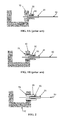
- FIG. 1A is a cross-section of a conventional feedthrough design including an integrated package ferrule
- FIG. 1B is a cross-section of a conventional feedthrough design including a package ferrule sealed to a package;
- FIG. 2 is a cross-section of a hermetic feedthrough including a high-CTE package ferrule
- FIG. 3 is a cross-section of a hermetic feedthrough in accordance with one embodiment of this invention.
- FIG. 3A is a cross-section of a hermetic feedthrough in accordance with one embodiment of this invention.
- FIG. 4 is a cross-section of a hermetic feedthrough in accordance with one embodiment of this invention.
- FIG. 5 is a cross-section of a hermetic feedthrough in accordance with one embodiment of this invention.
- FIG. 6 is a partially dissected isometric view of the hermetic feedthrough shown in FIG. 5 ;
- FIG. 7 is an illustration of a feedthrough without a compression sleeve.
- FIGS. 1A and 1B show a conventional hermetic feedthrough between an optical fiber and a package housing an optical device.
- An optical fiber 50 is attached to a package 10 using a fiber ferrule 20 and a package ferrule 30 .
- the package 10 and the package ferrule are made of low-CTE material(s) and the fiber ferrule is made of high-CTE material.
- the package 10 is made of Kovar (CTE ⁇ 5.5 ppm/C)
- the fiber ferrule 20 is made of brass (CTE ⁇ 20 ppm/C)
- the package ferrule 30 is made of the same material as the package 10 .
- FIG. 1A shows the package ferrule 30 integrated with the package 10
- FIG. 1B shows the package ferrule 30 brazed/soldered onto the package 10 with a joint 70
- the package ferrule 30 is made of the same material as the package 10 so as to avoid thermally induced stress in the joint 70 therebetween.
- a joint 60 between the fiber ferrule 20 and the package ferrule 30 is under significant tensile stress: when portions of the fiber ferrule 20 and the package ferrule 30 adjacent to the solder joint 60 cool below the soldering temperature, the package ferrule 30 , because of its low CTE, prevents contraction of the fiber ferrule 20 made of a high CTE material.
- the tensile stress “tears apart” the joint 60 and causes its deterioration. Since conventionally used solders have a limited fatigue life, it is highly desirable to minimize tensile stress in the joint.
- a package ferrule 35 shown in FIG. 2 is made of a high CTE material, similar to that of the fiber ferrule 20 , e.g. brass or Aluminum, so that thermal stress is minimal in the joint 65 .
- the high CTE package ferrule 35 may be brazed/soldered onto the low CTE package 10 ; consequently, a joint 75 experiences high tensile stresses. This presents a problem as the package to package-ferrule joint requires a high temperature in the process hierarchy, as it is done prior to the fiber-ferrule to package-ferrule soldering.
- a hermetic feedthrough includes a compression sleeve 100 made of high-CTE material.
- the compression sleeve 100 is hermetically sealed around the low CTE package ferrule 30 .
- the CTE of the compression sleeve 100 is greater than the CTE of the package ferrule 30 so as to create compressive stress in a joint 110 between the compression sleeve 100 and the package ferrule 30 , thereby enhancing fatigue reliability of the seal under thermal cycling.
- the compressive stress is generated in the compressive joint 110 as the high CTE material of the sleeve 100 squeezes the low CTE material of the package ferrule 30 in radial, tangential and longitudinal directions.
- the length of the braze/solder joint 110 does not need be large in this case due to compressive state of stress.
- hermetic sealing of two components together may be done by brazing or soldering, which depends on the materials to be sealed. In most cases they are soldered using relatively low temperature solders such as InSn, at ⁇ 120 C. The soldering temperature of the compression sleeve is less than that of the optical fiber solder to avoid reflow of that joint during the compression seal soldering.
- a fiber ferrule 25 is hermetically sealed around an optical fiber 50 and also it is sealed, i.e. brazed or soldered, inside the sleeve ferrule 100 .
- the fiber ferrule 25 and the compression sleeve 100 are made of high-CTE materials; they may be made of a same material so as to eliminate stress therebetween; or they may be integral parts of an integrated ferrule 125 shown in FIG. 3A .
- CTE of the compression sleeve were not less than a CTE of the fiber ferrule 25 so as to avoid tensile stress in a joint therebetween.
- the difference should be within approximately 3 ppm/C to avoid significant tensile stresses.
- the low CTE package ferrule 30 may be integral with the package 10 or sealed thereto as shown in FIGS. 1A and 1B .
- the package 10 and package ferrule 30 are thermally matched, i.e. they have equal CTEs, which is always the case when they are made of a same material.
- the external diameters of the fiber ferrule 25 and the package ferrule 30 are practically the same and typically are in the range of 1.5 mm to 2.5 mm; they correspond to the internal diameter of the sleeve 100 , leaving space for the solder joint 110 .
- a first length part of the compression sleeve 100 is hermetically sealed around the fiber ferrule 25 and a second length part of the compression sleeve 100 is hermetically sealed around the package ferrule 30 .
- the length of the fiber ferrule 25 typically varies between 10 mm and 20 mm and the package ferrule 30 may protrude from the package wall by approximately 6 mm.
- Wall thicknesses of the fiber ferrule 25 , the package ferrule 30 , and the sleeve 100 depend on the materials used and may vary in the range of 0.5 to 1 mm.
- the terms “high-CTE” and “low-CTE” used in this application relate to a first and a second materials such that a CTE of the first material is greater than a CTE of the second material.
- the difference in the CTE's may be greater than 5 ppm/C to create compression seal, but the difference is 10-15 ppm/C is more preferable.
- the package 10 and package ferrule 30 may be made of low-CTE materials which have a CTE less than 10 ppm/C and preferably less than 8 ppm/C, such as kovar and invar alloys.
- Typical materials for the fiber ferrules 20 and 25 and the sleeves 100 and 200 have a high CTE, i.e. greater than 13 ppm/C and preferably greater than 20 ppm/C; the materials may include aluminum, copper, and brass.
- the difference in CTE between the sleeve 100 and the package ferrule 25 , or the sleeve 200 and the package ferrule 20 shown in FIG. 4 may be as little as 1 ppm/C in order to avoid tensile stress in the joints. Preferably, the difference is above 5 ppm/C so as to produce significant compressive stress.
- the low-CTE materials being kovar and invar and high-CTE materials being aluminum and brass
- the CTE difference is between 10 and 15 ppm/C.
- the actual minimum CTE difference is dependent on the solder thickness between the sleeve and package ferrule; it is conceivable to have even less than 5 ppm/C difference if the solder thickness is extremely thin, e.g. 5 um.
- a method of fabricating a hermetic feedthrough for the optical fiber 50 into an optical module package 10 as shown in FIG. 3 comprises: providing the optical fiber 50 mounted and soldered inside the fiber ferrule 25 ; by way of example a BiSn solder is used and the fiber ferrule 25 is made of brass; brazing or soldering the fiber ferrule 25 into a portion of the compression sleeve 100 ; and, brazing or soldering another portion of the compression sleeve 100 around the package ferrule 30 .
- the compression sleeve 100 may first sealed to the package ferrule 30 , and then the fiber ferrule 25 with the fiber 50 mounted therein is inserted and brazed or soldered to the sleeve 100 .
- a hermetic feedthrough is formed using an integrated ferrule shown in grey in FIG. 4 .
- the integrated ferrule includes a fiber ferrule portion 20 , hermetically sealed around the optical fiber 50 , and a compression sleeve portion 200 , hermetically sealed around the package ferrule 30 .
- a CTE of the integrated ferrule and thus of the compression sleeve 200 is greater than a CTE of the package ferrule 30 so as to form a compressive joint 80 as discussed above with reference to FIG. 3 .
- the integrated ferrule or at least a portion thereof, has “U”-shaped cross section, the fiber ferrule 20 forming one arm of the “U,” and the compression sleeve 200 forming another arm of the “U;” an end of the package ferrule 30 is inserted into the opening of the “U” as shown in FIG. 4 .
- the integrated ferrule connects the fiber ferrule 20 and the compression sleeve 200 and covers an external, i.e. distal from the package, edge of a seal joint 85 between the low-CTE package ferrule 30 and the high-CTE fiber ferrule 20 , thus preventing contamination of the package interior through the joint 85 which may be subjected to tensile stress.
- the package ferrule 30 may be sealed to the package 10 or integral therewith.
- the fiber ferrule is formed of two or more parts sealed together; an internal part sealed to the optical fiber, and an external part sealed to the compression sleeve as shown in FIG. 3 or to the package ferrule as shown in FIG. 4 .
- an inner ferrule 20 b and a spacer 20 a constitute a fiber ferrule 20 which may replace the fiber ferrule shown in FIG. 4 .
- the spacer 20 a is integral with the compression sleeve 200 .
- the integrated ferrule in this case is formed of the inner ferrule 20 b , the spacer 20 a , and the compression sleeve 200 .
- FIG. 6 illustrates the same embodiment shown in FIG. 5 .
- the spacer 20 a is designed as an adaptor between the high CTE internal ferrule, or tube, 20 b and the low CTE package ferrule 30 , and forms a hermetic al seal with two solder joints connecting to the tube 20 b and ferrule 30 respectively.
- the thermal coefficient of the spacer 20 a is chosen to be close to that of the optical fiber tube 20 b so as to minimize thermal stress in the solder joint 210 between the tube 20 b and spacer 20 a .
- the CTE of the spacer 20 a is no less than the CTE of the optical fiber tube 20 b so as not to create tensile stress in the joint 210 therebetween.
- the cross section of a solder joint 220 which includes joint portions 80 and 85 shown in FIG. 4 , between the spacer 20 a , the compression sleeve 200 and low-CTE ferrule 30 is designed in a “U” shape. Since the thermal expansion of the spacer 20 a and the compression sleeve 200 is higher than that of the package ferrule 30 , during cooling down of the seal after the solder joint 220 has been formed at high temperature, the contraction of the spacer 20 a and the compression sleeve 200 is faster than that of the package ferrule 30 . Consequently, the solder joint 220 at the outer arm of the “U” is under compressive stress. The internal arm of the “U” is protected from contamination the same way as it is discussed above with reference to the joint portion 85 in FIG. 4 .
- FIG. 7 has not compression sleeve and thus lacks the advantage of the embodiments shown in FIGS. 3-6 .
- a method of fabricating a hermetic feedthrough for an optical fiber 50 into an optical module package 10 comprises:
- the optical fiber 50 mounted and soldered inside the fiber tube 20 b by way of example a BiSn solder is used and the fiber tube 20 b is made of brass;
- the integral element formed of the compression sleeve and the spacer can be brazed or soldered simultaneously to the package ferrule 30 and the fiber tube 20 b.
Abstract
Description
Claims (9)
Priority Applications (3)
| Application Number | Priority Date | Filing Date | Title |
|---|---|---|---|
| US12/750,084 US8342756B2 (en) | 2009-12-22 | 2010-03-30 | Hermetic seal between a package and an optical fiber |
| EP10191951.2A EP2339385B1 (en) | 2009-12-22 | 2010-11-19 | Hermetic seal between a package and an optical fiber |
| CN201010586977.8A CN102103237B (en) | 2009-12-22 | 2010-12-14 | Hermetic seal between packaging part and optical fiber |
Applications Claiming Priority (2)
| Application Number | Priority Date | Filing Date | Title |
|---|---|---|---|
| US28897009P | 2009-12-22 | 2009-12-22 | |
| US12/750,084 US8342756B2 (en) | 2009-12-22 | 2010-03-30 | Hermetic seal between a package and an optical fiber |
Publications (2)
| Publication Number | Publication Date |
|---|---|
| US20110170833A1 US20110170833A1 (en) | 2011-07-14 |
| US8342756B2 true US8342756B2 (en) | 2013-01-01 |
Family
ID=43641002
Family Applications (1)
| Application Number | Title | Priority Date | Filing Date |
|---|---|---|---|
| US12/750,084 Active 2030-08-25 US8342756B2 (en) | 2009-12-22 | 2010-03-30 | Hermetic seal between a package and an optical fiber |
Country Status (3)
| Country | Link |
|---|---|
| US (1) | US8342756B2 (en) |
| EP (1) | EP2339385B1 (en) |
| CN (1) | CN102103237B (en) |
Cited By (5)
| Publication number | Priority date | Publication date | Assignee | Title |
|---|---|---|---|---|
| US9213148B2 (en) | 2012-04-11 | 2015-12-15 | Nanoprecision Products, Inc. | Hermetic optical fiber alignment assembly |
| US9656439B2 (en) | 2013-07-10 | 2017-05-23 | Lumentum Operations Llc | Assembly of components having different coefficients of thermal expansion |
| US20180081132A1 (en) * | 2012-03-05 | 2018-03-22 | Nanoprecision Products, Inc. | Coupling device having a structured reflective surface for coupling input/output of an optical fiber |
| CN110291688A (en) * | 2017-02-14 | 2019-09-27 | 古河电气工业株式会社 | Optical element packaging part and optical element module |
| US10754110B2 (en) | 2012-03-05 | 2020-08-25 | Cudoquanta Florida, Inc. | Optical bench subassembly having integrated photonic device |
Families Citing this family (5)
| Publication number | Priority date | Publication date | Assignee | Title |
|---|---|---|---|---|
| US9500808B2 (en) * | 2012-05-09 | 2016-11-22 | The Boeing Company | Ruggedized photonic crystal sensor packaging |
| JP6226782B2 (en) * | 2014-03-13 | 2017-11-08 | オリンパス株式会社 | Optical transmission module and optical transmission module manufacturing method |
| US10481344B2 (en) | 2017-11-21 | 2019-11-19 | Lumentum Operations Llc | High density optical fiber feedthrough |
| JP6995384B2 (en) * | 2019-08-22 | 2022-01-14 | 湖北工業株式会社 | Fiber optic feedthrough |
| CN112993745B (en) * | 2019-12-13 | 2022-06-10 | 潍坊华光光电子有限公司 | Pin structure for improving TO packaging airtightness and sintering method |
Citations (19)
| Publication number | Priority date | Publication date | Assignee | Title |
|---|---|---|---|---|
| EP0383511A2 (en) | 1989-02-16 | 1990-08-22 | Nortel Networks Corporation | Hermetic gland for optical fibres |
| US5177806A (en) | 1986-12-05 | 1993-01-05 | E. I. Du Pont De Nemours And Company | Optical fiber feedthrough |
| EP0631164A1 (en) | 1993-06-23 | 1994-12-28 | Hitachi, Ltd. | Optical element module |
| US5386488A (en) | 1992-04-02 | 1995-01-31 | Fujitsu Limited | Optical module and manufacturing method therefor |
| US5613031A (en) | 1994-06-29 | 1997-03-18 | Nec Corporation | Hermetically sealed optical fiber insert structure |
| US5689608A (en) | 1992-11-23 | 1997-11-18 | Alcatel Network Systems, Inc. | Fiber optic assembly |
| US5970194A (en) | 1998-02-19 | 1999-10-19 | Uniphase Telecommunications Products, Inc. | Optical fiber having hermetically sealable section |
| US20020179683A1 (en) | 2001-06-01 | 2002-12-05 | Carrier Geary R. | Hermetic optical fiber seal |
| US20030190135A1 (en) * | 2002-04-03 | 2003-10-09 | Moidu Abdul Jaleel J. | Hermetic waveguide seals and method of making them |
| US6633720B1 (en) | 2001-03-30 | 2003-10-14 | Avanex Corporation | Hermetic seal feed-through assembly for optical fiber |
| US6643446B2 (en) | 2001-11-27 | 2003-11-04 | Jds Uniphase Inc. | Hermetic fiber ferrule and feedthrough |
| US20040052481A1 (en) | 2002-09-18 | 2004-03-18 | Francois Seguin | Optical component packaging device |
| JP2004177613A (en) | 2002-11-26 | 2004-06-24 | Sumitomo Electric Ind Ltd | Optical module |
| US6788873B2 (en) | 2001-12-01 | 2004-09-07 | Schott Glas | Method of hermetically sealing a fiber optic light guide in a metallic feedthrough sleeve with glass solder and hermetically sealed feedthrough device made thereby |
| US6837075B1 (en) | 2000-10-27 | 2005-01-04 | Bookham Technology, Plc. | Glass fiber fixative and fixing process |
| US20050058411A1 (en) | 2003-09-15 | 2005-03-17 | Finot Marc A. | Hermetic sealing of optical module |
| US6922518B2 (en) | 2002-12-13 | 2005-07-26 | Lighthouse Capital Partners | Methods and apparatus for sealed fiber optic feedthroughs |
| US6962338B2 (en) | 2002-02-22 | 2005-11-08 | Jds Uniphase Inc. | Hermetic seal and a method of making such a hermetic seal |
| US20080025677A1 (en) | 2006-07-26 | 2008-01-31 | Fujitsu Limited | Optical device and manufacturing method thereof |
-
2010
- 2010-03-30 US US12/750,084 patent/US8342756B2/en active Active
- 2010-11-19 EP EP10191951.2A patent/EP2339385B1/en active Active
- 2010-12-14 CN CN201010586977.8A patent/CN102103237B/en active Active
Patent Citations (19)
| Publication number | Priority date | Publication date | Assignee | Title |
|---|---|---|---|---|
| US5177806A (en) | 1986-12-05 | 1993-01-05 | E. I. Du Pont De Nemours And Company | Optical fiber feedthrough |
| EP0383511A2 (en) | 1989-02-16 | 1990-08-22 | Nortel Networks Corporation | Hermetic gland for optical fibres |
| US5386488A (en) | 1992-04-02 | 1995-01-31 | Fujitsu Limited | Optical module and manufacturing method therefor |
| US5689608A (en) | 1992-11-23 | 1997-11-18 | Alcatel Network Systems, Inc. | Fiber optic assembly |
| EP0631164A1 (en) | 1993-06-23 | 1994-12-28 | Hitachi, Ltd. | Optical element module |
| US5613031A (en) | 1994-06-29 | 1997-03-18 | Nec Corporation | Hermetically sealed optical fiber insert structure |
| US5970194A (en) | 1998-02-19 | 1999-10-19 | Uniphase Telecommunications Products, Inc. | Optical fiber having hermetically sealable section |
| US6837075B1 (en) | 2000-10-27 | 2005-01-04 | Bookham Technology, Plc. | Glass fiber fixative and fixing process |
| US6633720B1 (en) | 2001-03-30 | 2003-10-14 | Avanex Corporation | Hermetic seal feed-through assembly for optical fiber |
| US20020179683A1 (en) | 2001-06-01 | 2002-12-05 | Carrier Geary R. | Hermetic optical fiber seal |
| US6643446B2 (en) | 2001-11-27 | 2003-11-04 | Jds Uniphase Inc. | Hermetic fiber ferrule and feedthrough |
| US6788873B2 (en) | 2001-12-01 | 2004-09-07 | Schott Glas | Method of hermetically sealing a fiber optic light guide in a metallic feedthrough sleeve with glass solder and hermetically sealed feedthrough device made thereby |
| US6962338B2 (en) | 2002-02-22 | 2005-11-08 | Jds Uniphase Inc. | Hermetic seal and a method of making such a hermetic seal |
| US20030190135A1 (en) * | 2002-04-03 | 2003-10-09 | Moidu Abdul Jaleel J. | Hermetic waveguide seals and method of making them |
| US20040052481A1 (en) | 2002-09-18 | 2004-03-18 | Francois Seguin | Optical component packaging device |
| JP2004177613A (en) | 2002-11-26 | 2004-06-24 | Sumitomo Electric Ind Ltd | Optical module |
| US6922518B2 (en) | 2002-12-13 | 2005-07-26 | Lighthouse Capital Partners | Methods and apparatus for sealed fiber optic feedthroughs |
| US20050058411A1 (en) | 2003-09-15 | 2005-03-17 | Finot Marc A. | Hermetic sealing of optical module |
| US20080025677A1 (en) | 2006-07-26 | 2008-01-31 | Fujitsu Limited | Optical device and manufacturing method thereof |
Cited By (10)
| Publication number | Priority date | Publication date | Assignee | Title |
|---|---|---|---|---|
| US20180081132A1 (en) * | 2012-03-05 | 2018-03-22 | Nanoprecision Products, Inc. | Coupling device having a structured reflective surface for coupling input/output of an optical fiber |
| US10754110B2 (en) | 2012-03-05 | 2020-08-25 | Cudoquanta Florida, Inc. | Optical bench subassembly having integrated photonic device |
| US10754107B2 (en) * | 2012-03-05 | 2020-08-25 | Cudoquanta Florida, Inc. | Coupling device having a structured reflective surface of stamped malleable metal for coupling input/output of an optical fiber |
| US9213148B2 (en) | 2012-04-11 | 2015-12-15 | Nanoprecision Products, Inc. | Hermetic optical fiber alignment assembly |
| US20160187599A1 (en) * | 2012-04-11 | 2016-06-30 | Nanoprecision Products, Inc. | Hermetic optical fiber alignment assembly |
| US9656439B2 (en) | 2013-07-10 | 2017-05-23 | Lumentum Operations Llc | Assembly of components having different coefficients of thermal expansion |
| US11040514B2 (en) | 2013-07-10 | 2021-06-22 | Lumentum Operations Llc | Assembly of components having different coefficients of thermal expansion |
| US11845257B2 (en) | 2013-07-10 | 2023-12-19 | Lumentum Operations Llc | Assembly of components having different coefficients of thermal expansion |
| CN110291688A (en) * | 2017-02-14 | 2019-09-27 | 古河电气工业株式会社 | Optical element packaging part and optical element module |
| US10978851B2 (en) | 2017-02-14 | 2021-04-13 | Furukawa Electric Co., Ltd. | Package for optical device and optical device module |
Also Published As
| Publication number | Publication date |
|---|---|
| CN102103237B (en) | 2015-09-02 |
| CN102103237A (en) | 2011-06-22 |
| EP2339385B1 (en) | 2014-12-03 |
| EP2339385A1 (en) | 2011-06-29 |
| US20110170833A1 (en) | 2011-07-14 |
Similar Documents
| Publication | Publication Date | Title |
|---|---|---|
| US8342756B2 (en) | Hermetic seal between a package and an optical fiber | |
| EP0221180B1 (en) | Hermetic fiber seal | |
| US20110158594A1 (en) | Optical module with fiber feedthrough | |
| US20020122653A1 (en) | Hermetically sealed fiber tail assembly | |
| US20030099453A1 (en) | Hermetic fiber ferrule and feedthrough | |
| JP2616668B2 (en) | Hermetically sealed structure of optical fiber introduction section | |
| JP2524463B2 (en) | Airtight sealing method for optical fiber introduction part | |
| JP6095495B2 (en) | Optical element sealing structure for laser ignition device, method for manufacturing the same, and laser ignition device | |
| US10761277B2 (en) | Hermetic optical fiber stub with connector interface and vent | |
| US20040184753A1 (en) | Fiber module in which optical fiber coated with metal or inorganic material is fixed to sealable package so that an end of the optical fiber appears inside the package | |
| JP6935206B2 (en) | Optical element package and optical element module | |
| US6974266B2 (en) | Optical component packaging device | |
| JP5825315B2 (en) | Optical element module | |
| US6922518B2 (en) | Methods and apparatus for sealed fiber optic feedthroughs | |
| US20020179683A1 (en) | Hermetic optical fiber seal | |
| US20050047733A1 (en) | Method and structure for packaging fiber optics device | |
| JP2004252423A (en) | Fiber module and manufacturing method therefor | |
| JP5419780B2 (en) | Ferrule for fixing optical fiber and optical fiber fixture using the same | |
| Dietz | Optical fiber sealing with solder glass: design guidelines | |
| US20220283379A1 (en) | Optical fiber feedthrough | |
| JP4308049B2 (en) | Semiconductor element module | |
| JP5213348B2 (en) | Optical fiber coupler | |
| JP4090915B2 (en) | Fiber collimator, optical component, and method for manufacturing optical component | |
| Kreutzmann | Solder glass-sealing technology for use in packaging of fiber optic sensors | |
| JP3847178B2 (en) | Hermetic sealing structure of optical fiber and optical fiber array using the same |
Legal Events
| Date | Code | Title | Description |
|---|---|---|---|
| AS | Assignment |
Owner name: JDS UNIPHASE CORPORATION, CALIFORNIA Free format text: ASSIGNMENT OF ASSIGNORS INTEREST;ASSIGNORS:MOIDU, ABDUL JALEEL K.;JIN, WENLIN;REEL/FRAME:024291/0963 Effective date: 20100423 |
|
| STCF | Information on status: patent grant |
Free format text: PATENTED CASE |
|
| AS | Assignment |
Owner name: LUMENTUM OPERATIONS LLC, CALIFORNIA Free format text: ASSIGNMENT OF ASSIGNORS INTEREST;ASSIGNOR:JDS UNIPHASE CORPORATION;REEL/FRAME:036420/0340 Effective date: 20150731 |
|
| FEPP | Fee payment procedure |
Free format text: PAYOR NUMBER ASSIGNED (ORIGINAL EVENT CODE: ASPN); ENTITY STATUS OF PATENT OWNER: LARGE ENTITY |
|
| AS | Assignment |
Owner name: LUMENTUM OPERATIONS LLC, CALIFORNIA Free format text: CORRECTIVE ASSIGNMENT TO CORRECT THE PATENTS LISTED ON PAGE A-A33 PREVIOUSLY RECORDED ON REEL 036420 FRAME 0340. ASSIGNOR(S) HEREBY CONFIRMS THE PATENT NUMBERS 7,868,247 AND 6,476,312 WERE LISTED IN ERROR AND SHOULD BE REMOVED;ASSIGNOR:JDS UNIPHASE CORPORATION;REEL/FRAME:037562/0513 Effective date: 20150731 Owner name: LUMENTUM OPERATIONS LLC, CALIFORNIA Free format text: CORRECTIVE ASSIGNMENT TO CORRECT INCORRECT PATENTS 7,868,247 AND 6,476,312 ON PAGE A-A33 PREVIOUSLY RECORDED ON REEL 036420 FRAME 0340. ASSIGNOR(S) HEREBY CONFIRMS THE ASSIGNMENT;ASSIGNOR:JDS UNIPHASE CORPORATION;REEL/FRAME:037562/0513 Effective date: 20150731 |
|
| AS | Assignment |
Owner name: LUMENTUM OPERATIONS LLC, CALIFORNIA Free format text: CORRECTIVE ASSIGNMENT TO CORRECT THE PATENTS LISTED ON PAGE A-A33 PATENT NUMBERS 7,868,247 AND 6,476,312 WERE LISTED IN ERROR AND SHOULD BE REMOVED. PREVIOUSLY RECORDED ON REEL 036420 FRAME 0340. ASSIGNOR(S) HEREBY CONFIRMS THE ASSIGNMENT;ASSIGNOR:JDS UNIPHASE CORPORATION;REEL/FRAME:037627/0641 Effective date: 20150731 Owner name: LUMENTUM OPERATIONS LLC, CALIFORNIA Free format text: CORRECTIVE ASSIGNMENT TO CORRECT PATENTS 7,868,247 AND 6,476,312 LISTED ON PAGE A-A33 PREVIOUSLY RECORDED ON REEL 036420 FRAME 0340. ASSIGNOR(S) HEREBY CONFIRMS THE ASSIGNMENT;ASSIGNOR:JDS UNIPHASE CORPORATION;REEL/FRAME:037627/0641 Effective date: 20150731 |
|
| FPAY | Fee payment |
Year of fee payment: 4 |
|
| AS | Assignment |
Owner name: DEUTSCHE BANK AG NEW YORK BRANCH, AS COLLATERAL AGENT, NEW YORK Free format text: PATENT SECURITY AGREEMENT;ASSIGNORS:LUMENTUM OPERATIONS LLC;OCLARO FIBER OPTICS, INC.;OCLARO, INC.;REEL/FRAME:047788/0511 Effective date: 20181210 Owner name: DEUTSCHE BANK AG NEW YORK BRANCH, AS COLLATERAL AG Free format text: PATENT SECURITY AGREEMENT;ASSIGNORS:LUMENTUM OPERATIONS LLC;OCLARO FIBER OPTICS, INC.;OCLARO, INC.;REEL/FRAME:047788/0511 Effective date: 20181210 |
|
| AS | Assignment |
Owner name: LUMENTUM OPERATIONS LLC, CALIFORNIA Free format text: RELEASE BY SECURED PARTY;ASSIGNOR:DEUTSCHE AG NEW YORK BRANCH;REEL/FRAME:051287/0556 Effective date: 20191212 Owner name: OCLARO, INC., CALIFORNIA Free format text: RELEASE BY SECURED PARTY;ASSIGNOR:DEUTSCHE AG NEW YORK BRANCH;REEL/FRAME:051287/0556 Effective date: 20191212 Owner name: OCLARO FIBER OPTICS, INC., CALIFORNIA Free format text: RELEASE BY SECURED PARTY;ASSIGNOR:DEUTSCHE AG NEW YORK BRANCH;REEL/FRAME:051287/0556 Effective date: 20191212 |
|
| MAFP | Maintenance fee payment |
Free format text: PAYMENT OF MAINTENANCE FEE, 8TH YEAR, LARGE ENTITY (ORIGINAL EVENT CODE: M1552); ENTITY STATUS OF PATENT OWNER: LARGE ENTITY Year of fee payment: 8 |