US8414151B2 - Light emitting diode (LED) based lamp - Google Patents
Light emitting diode (LED) based lamp Download PDFInfo
- Publication number
- US8414151B2 US8414151B2 US12/896,314 US89631410A US8414151B2 US 8414151 B2 US8414151 B2 US 8414151B2 US 89631410 A US89631410 A US 89631410A US 8414151 B2 US8414151 B2 US 8414151B2
- Authority
- US
- United States
- Prior art keywords
- diffuser
- led
- light emitting
- set forth
- light source
- Prior art date
- Legal status (The legal status is an assumption and is not a legal conclusion. Google has not performed a legal analysis and makes no representation as to the accuracy of the status listed.)
- Active, expires
Links
Images


Classifications
-
- F—MECHANICAL ENGINEERING; LIGHTING; HEATING; WEAPONS; BLASTING
- F21—LIGHTING
- F21V—FUNCTIONAL FEATURES OR DETAILS OF LIGHTING DEVICES OR SYSTEMS THEREOF; STRUCTURAL COMBINATIONS OF LIGHTING DEVICES WITH OTHER ARTICLES, NOT OTHERWISE PROVIDED FOR
- F21V3/00—Globes; Bowls; Cover glasses
-
- F—MECHANICAL ENGINEERING; LIGHTING; HEATING; WEAPONS; BLASTING
- F21—LIGHTING
- F21K—NON-ELECTRIC LIGHT SOURCES USING LUMINESCENCE; LIGHT SOURCES USING ELECTROCHEMILUMINESCENCE; LIGHT SOURCES USING CHARGES OF COMBUSTIBLE MATERIAL; LIGHT SOURCES USING SEMICONDUCTOR DEVICES AS LIGHT-GENERATING ELEMENTS; LIGHT SOURCES NOT OTHERWISE PROVIDED FOR
- F21K9/00—Light sources using semiconductor devices as light-generating elements, e.g. using light-emitting diodes [LED] or lasers
- F21K9/20—Light sources comprising attachment means
- F21K9/23—Retrofit light sources for lighting devices with a single fitting for each light source, e.g. for substitution of incandescent lamps with bayonet or threaded fittings
- F21K9/232—Retrofit light sources for lighting devices with a single fitting for each light source, e.g. for substitution of incandescent lamps with bayonet or threaded fittings specially adapted for generating an essentially omnidirectional light distribution, e.g. with a glass bulb
-
- F—MECHANICAL ENGINEERING; LIGHTING; HEATING; WEAPONS; BLASTING
- F21—LIGHTING
- F21K—NON-ELECTRIC LIGHT SOURCES USING LUMINESCENCE; LIGHT SOURCES USING ELECTROCHEMILUMINESCENCE; LIGHT SOURCES USING CHARGES OF COMBUSTIBLE MATERIAL; LIGHT SOURCES USING SEMICONDUCTOR DEVICES AS LIGHT-GENERATING ELEMENTS; LIGHT SOURCES NOT OTHERWISE PROVIDED FOR
- F21K9/00—Light sources using semiconductor devices as light-generating elements, e.g. using light-emitting diodes [LED] or lasers
- F21K9/60—Optical arrangements integrated in the light source, e.g. for improving the colour rendering index or the light extraction
- F21K9/66—Details of globes or covers forming part of the light source
-
- F—MECHANICAL ENGINEERING; LIGHTING; HEATING; WEAPONS; BLASTING
- F21—LIGHTING
- F21V—FUNCTIONAL FEATURES OR DETAILS OF LIGHTING DEVICES OR SYSTEMS THEREOF; STRUCTURAL COMBINATIONS OF LIGHTING DEVICES WITH OTHER ARTICLES, NOT OTHERWISE PROVIDED FOR
- F21V29/00—Protecting lighting devices from thermal damage; Cooling or heating arrangements specially adapted for lighting devices or systems
- F21V29/50—Cooling arrangements
- F21V29/70—Cooling arrangements characterised by passive heat-dissipating elements, e.g. heat-sinks
- F21V29/74—Cooling arrangements characterised by passive heat-dissipating elements, e.g. heat-sinks with fins or blades
- F21V29/77—Cooling arrangements characterised by passive heat-dissipating elements, e.g. heat-sinks with fins or blades with essentially identical diverging planar fins or blades, e.g. with fan-like or star-like cross-section
-
- F—MECHANICAL ENGINEERING; LIGHTING; HEATING; WEAPONS; BLASTING
- F21—LIGHTING
- F21V—FUNCTIONAL FEATURES OR DETAILS OF LIGHTING DEVICES OR SYSTEMS THEREOF; STRUCTURAL COMBINATIONS OF LIGHTING DEVICES WITH OTHER ARTICLES, NOT OTHERWISE PROVIDED FOR
- F21V3/00—Globes; Bowls; Cover glasses
- F21V3/02—Globes; Bowls; Cover glasses characterised by the shape
-
- F—MECHANICAL ENGINEERING; LIGHTING; HEATING; WEAPONS; BLASTING
- F21—LIGHTING
- F21V—FUNCTIONAL FEATURES OR DETAILS OF LIGHTING DEVICES OR SYSTEMS THEREOF; STRUCTURAL COMBINATIONS OF LIGHTING DEVICES WITH OTHER ARTICLES, NOT OTHERWISE PROVIDED FOR
- F21V29/00—Protecting lighting devices from thermal damage; Cooling or heating arrangements specially adapted for lighting devices or systems
- F21V29/50—Cooling arrangements
- F21V29/60—Cooling arrangements characterised by the use of a forced flow of gas, e.g. air
- F21V29/67—Cooling arrangements characterised by the use of a forced flow of gas, e.g. air characterised by the arrangement of fans
- F21V29/677—Cooling arrangements characterised by the use of a forced flow of gas, e.g. air characterised by the arrangement of fans the fans being used for discharging
-
- F—MECHANICAL ENGINEERING; LIGHTING; HEATING; WEAPONS; BLASTING
- F21—LIGHTING
- F21V—FUNCTIONAL FEATURES OR DETAILS OF LIGHTING DEVICES OR SYSTEMS THEREOF; STRUCTURAL COMBINATIONS OF LIGHTING DEVICES WITH OTHER ARTICLES, NOT OTHERWISE PROVIDED FOR
- F21V29/00—Protecting lighting devices from thermal damage; Cooling or heating arrangements specially adapted for lighting devices or systems
- F21V29/50—Cooling arrangements
- F21V29/70—Cooling arrangements characterised by passive heat-dissipating elements, e.g. heat-sinks
- F21V29/83—Cooling arrangements characterised by passive heat-dissipating elements, e.g. heat-sinks the elements having apertures, ducts or channels, e.g. heat radiation holes
-
- F—MECHANICAL ENGINEERING; LIGHTING; HEATING; WEAPONS; BLASTING
- F21—LIGHTING
- F21Y—INDEXING SCHEME ASSOCIATED WITH SUBCLASSES F21K, F21L, F21S and F21V, RELATING TO THE FORM OR THE KIND OF THE LIGHT SOURCES OR OF THE COLOUR OF THE LIGHT EMITTED
- F21Y2115/00—Light-generating elements of semiconductor light sources
- F21Y2115/10—Light-emitting diodes [LED]
Definitions
- the following relates to the illumination arts, lighting arts, solid-state lighting arts, and related arts.
- Integral incandescent and halogen lamps are designed as direct “plug-in” components that mate with a lamp socket via a threaded Edison base connector (sometimes referred to as an “Edison base” in the context of an incandescent light bulb), a bayonet-type base connector (i.e., bayonet base in the case of an incandescent light bulb), or other standard base connector to receive standard electrical power (e.g., 110 volts a.c., 60 Hz in the United States, or 220V a.c., 50 Hz in Europe, or 12 or 24 or other d.c. voltage).
- the integral lamp is constructed as a unitary package including any components needed to operate from the standard electrical power received at the base connector.
- the incandescent filament is typically operable using the standard 110V or 220V a.c., or 12V d.c., power, and the incandescent filament operates at high temperature and efficiently radiates excess heat into the ambient.
- the base of the lamp is simply the base connector, e.g. the Edison base in the case of an “A”-type incandescent light bulb.
- Some integral incandescent or halogen lamps are constructed as omni-directional light sources which are intended to provide substantially uniform intensity distribution versus angle in the optical far field, greater than 5 or 10 times the linear dimension of the light source, or typically greater than about 1 meter away from the lamp, and find diverse applications such as in desk lamps, table lamps, decorative lamps, chandeliers, ceiling fixtures, and other applications where a uniform distribution of light in all directions is desired.
- a coordinate system which is used herein to describe the spatial distribution of illumination generated by a lamp intended to produce omnidirectional illumination.
- the coordinate system is of the spherical coordinate system type, and is described in FIG. 1 with reference to a lamp L, which in this illustrated embodiment is an “A”-type incandescent light bulb with an Edison base EB, which may for example be an E25, E26, or E27 lamp base where the numeral denotes the outer diameter of the screw turns on the base EB, in millimeters.
- the lamp L can be considered to be located at a point L 0 , which may for example coincide with the location of the incandescent filament.
- a direction of illumination can be described by an elevation or latitude coordinate ⁇ and an azimuth or longitude coordinate ⁇ .
- an azimuth, or longitude coordinate ⁇ can also be defined, which is everywhere orthogonal to the elevation or latitude ⁇ .
- the incandescent lamp L suitably employs an incandescent filament located at coordinate center L 0 which can be designed to emit substantially omnidirectional light, thus providing a uniform illumination distribution respective to the azimuth ⁇ for any latitude.
- a lamp that provides uniform illumination distribution respective to the azimuth ⁇ for any latitude is sometimes referred to as providing an axially symmetrical light distribution.
- This is generally considered an acceptable illumination distribution uniformity for an omnidirectional lamp, although there is some interest in extending this span still further, such as to a latitude span of ⁇ [0°, 150°] with and possibly with a better ⁇ 10% uniformity.
- LED replacement lamps that operate as direct “plug-in” replacements for integral incandescent or halogen lamps.
- substantial difficulties have heretofore hindered development of LED replacement lamps with desired omnidirectional intensity characteristics.
- solid-state lighting technologies such as light emitting diode (LED) devices are highly directional by nature.
- LED light emitting diode
- an LED chip or other solid state lighting device typically cannot be operated efficiently using standard 110V or 220V a.c. power. Rather, on-board electronics are typically provided to convert the a.c. input power to d.c. power of lower voltage amenable for driving the LED chips.
- on-board electronics are typically provided to convert the a.c. input power to d.c. power of lower voltage amenable for driving the LED chips.
- a series string of LED chips of sufficient number can be directly operated at 110V or 220V, and parallel arrangements of such strings with suitable polarity control (e.g., Zener diodes) can be operated at 110V or 220V a.c. power, albeit at substantially reduced power efficiency.
- the electronics constitute additional components of the lamp base as compared with the simple Edison base used in integral incandescent or halogen lamps.
- Heat sinking is yet another issue for omnidirectional replacement LED lamps. Heat sinking is employed because LED devices are highly temperature-sensitive as compared with incandescent or halogen filaments. The LED devices cannot be operated at the temperature of an incandescent filament (rather, the operating temperature should be around 100° C. or preferably lower). The lower operating temperature also reduces the effectiveness of radiative cooling.
- the base of the LED replacement lamp further includes (in addition to the Edison base connector and the electronics) a relatively large mass of heat sinking material positioned contacting or otherwise in good thermal contact with the LED device(s).
- the combination of electronics and heat sinking results in a large base that blocks “backward” illumination, which has heretofore substantially limited the ability to generate omnidirectional illumination using an LED replacement lamp.
- the heat sink in particular preferably has a large volume and also large surface area in order to dissipate heat away from the lamp by a combination of convection and radiation.
- a light emitting apparatus comprises: an LED-based light source; a spherical, spheroidal, ovoid, egg-shaped, or toroidal diffuser generating a light intensity distribution output responsive to illumination inside the diffuser; and a base including a base connector.
- the LED based light source, the diffuser, and the base are secured together as a unitary LED lamp installable in a lighting socket by connecting the base connector with the lighting socket.
- the base is operatively connected with the LED based light source in the unitary LED lamp to electrically power the LED based light source using electrical power received at the base connector.
- a light emitting apparatus comprises: a light assembly including an LED-based light source optically coupled with and arranged tangential to a spherical, spheroidal, ovoid, or egg-shaped diffuser; and a base including a base connector, the base configured to electrically power the LED based light source using electrical power received at the base connector.
- the light assembly and base are secured together as a unitary LED lamp installable in a lighting socket by connecting the base connector with the lighting socket.
- a light emitting apparatus comprises: a light assembly including a ring shaped LED-based light source optically coupled with a toroidal diffuser; and a base including a base connector and configured to electrically power the ring shaped LED based light source using electrical power received at the base connector.
- the light assembly and base are secured together as a unitary LED lamp installable in a lighting socket by connecting the base connector with the lighting socket.
- the invention may take form in various components and arrangements of components, and in various process operations and arrangements of process operations.
- the drawings are only for purposes of illustrating preferred embodiments and are not to be construed as limiting the invention.
- FIG. 1 diagrammatically shows, with reference to a conventional incandescent light bulb, a coordinate system that is used herein to describe illumination distributions.
- FIG. 2 diagrammatically shows a side view of an omnidirectional LED-based lamp employing a planar LED-based Lambertian light source and a spherical diffuser.
- FIG. 3 diagrammatically shows the omnidirectional LED-based lamp of FIG. 2 with the spherical diffuser lifted away to reveal the planar LED-based lambertian light source.
- FIG. 4 diagrammatically illustrates using ray tracing diagrams how the omnidirectional LED-based lamp of FIGS. 2 and 3 generates a substantially omnidirectional illumination distribution.
- FIGS. 5 and 6 show side views of two illustrative LED-based lamps employing the principles of the lamp of FIGS. 2-4 and each further including an Edison base enabling installation in a conventional incandescent lamp socket.
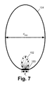
- FIG. 7 diagrammatically illustrates a side view of a variation on the embodiment of FIGS. 2-4 in which the light source emits a prolate-distorted Lambertian intensity distribution, and the diffuser is a prolate spheroidal diffuser having a shape matching the light source intensity distribution.
- FIG. 8 diagrammatically illustrates a side view of a variation on the embodiment of FIGS. 2-4 in which the light source emits a oblate-distorted Lambertian intensity distribution, and the diffuser is a oblate spheroidal diffuser having a shape matching the light source intensity distribution.
- FIG. 9 illustrates impact of position of the LED-based light source relative to a spherical diffuser on the blocking angle.
- FIG. 10 plots the impact on the latitudinal range of light uniformity of the ratio of a spherical diffuser diameter to the LED-based light source size.
- FIG. 11 shows a side perspective view of a retrofit LED-based light bulb substantially similar to the lamp of FIG. 5 but further including fins.
- FIG. 12 plots intensity versus latitude for two actually constructed embodiments of the retrofit LED-based light bulb of FIG. 11 .
- FIGS. 13 and 14 diagrammatically illustrate side and perspective side views, respectively, of a light source employing principles disclosed herein with a toroidal diffuser.
- FIG. 14A depicts a variant embodiment.
- FIGS. 15 , 16 , 17 , 18 , and 19 show perspective, alternative shaded perspective, side, top, and bottom views, respectively of in LED-based light bulb.
- FIGS. 20 and 21 show the diffuser of the lamp of FIGS. 15-19 including a side view and a shaded side sectional view revealing the interior of the diffuser, respectively.
- FIGS. 22 and 23 show a side view of the diffuser with the fins, and an exploded view of same, respectively.
- FIGS. 24 , 25 , and 26 compare the ovoid diffuser of the embodiment of FIGS. 15-23 with a spherical diffuser, with FIG. 25 showing differences in incident ray lengths for the ovoid versus spherical diffuser, and FIG. 26 showing scattering distributions for light passing out of the ovoid diffuser.
- FIGS. 27-30 show additional illustrative ovoid diffuser embodiments.
- FIGS. 31 and 32 show embodiments of the lamp of FIGS. 15-23 which further include selected auxiliary optical components.
- an LED-based lamp includes a planar LED-based Lambertian light source 8 and a light-transmissive spherical diffuser 10 .
- the planar LED-based Lambertian light source 8 is best seen in the partially disassembled view of FIG. 3 in which the diffuser 10 is pulled away and the planar LED-based Lambertian light source 8 is tilted into view.
- the planar LED-based Lambertian light source 8 includes a plurality of light emitting diode (LED) devices 12 , 14 , which in the illustrated embodiment include first LED devices 12 and second LED devices 14 having respective spectra and intensities that mix to render white light of a desired color temperature and CRI.
- LED light emitting diode
- the first LED devices 12 output white light having a greenish rendition (achievable, for example, by using a blue- or violet-emitting LED chip that is coated with a suitable “white” phosphor) and the second LED devices 14 output red light (achievable, for example, using a GaAsP or AlGaInP or other epitaxy LED chip that naturally emits red light), and the light from the first and second LED devices 12 , 14 blend together to produce improved white rendition.
- the planar LED-based Lambertian light source to comprise a single LED device, which may be a white LED device or a saturated color LED device or so forth.
- the LED devices 12 , 14 are mounted on a circuit board 16 , which is optionally a metal core printed circuit board (MCPCB).
- a base element 18 provides support and is also thermally conductive so that the base element 18 also defines a heat sink 18 having a substantial thermal conductance for heat sinking the LED devices 12 , 14 .
- the illustrated light-transmissive spherical diffuser 10 is substantially hollow and has a spherical surface that diffuses light.
- the spherical diffuser 10 is a glass element, although a diffuser of another light-transmissive material such as plastic or other material is also contemplated.
- the surface of the diffuser 10 may be inherently light-diffusive, or can be made light-diffusive in various ways, such as: frosting or other texturing to promote light diffusion; coating with a light-diffusive coating such as enamel paint, or a Soft-White or StarcoatTM diffusive coating (available from General Electric Company, New York, USA) of a type used as a light-diffusive coating on the glass bulbs of some incandescent or fluorescent light bulbs; embedding light-scattering particles in the glass, plastic, or other material of the spherical diffuser 10 ; various combinations thereof; or so forth.
- a light-diffusive coating such as enamel paint, or a Soft-White or StarcoatTM diffusive coating (available from General Electric Company, New York, USA) of a type used as a light-diffusive coating on the glass bulbs of some incandescent or fluorescent light bulbs
- the diffuser 10 optionally may also include a phosphor, for example coated on the spherical surface, to convert the light from the LEDs to another color, for example to convert blue or ultraviolet (UV) light from the LEDs to white light.
- a phosphor for example coated on the spherical surface, to convert the light from the LEDs to another color, for example to convert blue or ultraviolet (UV) light from the LEDs to white light.
- the phosphor it is contemplated for the phosphor to be the sole component of the diffuser 10 .
- the phosphor should be a diffusing phosphor.
- the diffuser includes a phosphor plus an additional diffusive element such as frosting, enamel paint, a coating, or so forth.
- the light-transmissive spherical diffuser 10 includes an aperture or opening 20 sized to receive or mate with the planar LED-based Lambertian light source 8 such that the light-emissive principle surface of the planar LED-based Lambertian light source 8 faces into the interior of the spherical diffuser 10 and emits light into the interior of the spherical diffuser 19 .
- the spherical diffuser is large compared with the area of the planar LED-based Lambertian light source 8 so that the light source 8 is arranged at a periphery of the substantially larger spherical diffuser 10 ; in the illustrated embodiment, the spherical diffuser 10 has a diameter d D while the planar LED-based Lambertian light source 8 (or, equivalently, the mating aperture or opening 20 ) has a circular area of diameter d L where d D >d L .
- the planar LED-based Lambertian light source 8 is mounted at or in the aperture or opening 20 with its planar light-emissive surface arranged tangential to the curved surface of the spherical diffuser 10 .
- the LED-based lamp is also describable using the spherical coordinates system of FIG. 1 , where the planar LED-based Lambertian light source 8 defines the coordinate system.
- the LED-based lamp of FIGS. 2-4 is rotationally symmetric about the optical axis and so there is no intensity variation respective to the azimuthal or longitudinal coordinate ⁇ .
- the flux (lumens/area), typically measured in units of lux (lumens/m 2 ), of light shining on the (inside) surface of the spherical diffuser 10 is of the same value at any point on the spherical diffuser 10 .
- the inside surface of the diffuser coincides with an isolux surface of the LED light source.
- the intensity decreases with the square of distance, and so the intensity is proportional to I o /I D 2 (where exact tangency of the light source 8 and the curvature of the diffuser 10 is here assumed as a simplification).
- the inside surface of a spherical diffuser having the LEDs positioned tangentially on the surface of the spherical diffuser is coincident with an iso lux contour surface of the intensity distribution of the LEDs.
- the diffuser 10 (assuming ideal light diffusion) emits a Lambertian light intensity distribution output at any point on its surface responsive to illumination inside the diffuser 10 by the LED-based light source 8 .
- the light intensity output at a point on the surface of the diffuser 10 responsive to illumination inside the spherical or spheroidal diffuser scales with cos( ⁇ ) where ⁇ is the viewing angle respective to the diffuser surface normal at that point.
- FIG. 4 shows the ray tracing diagrams for seven direct rays emitted by the planar LED-based Lambertian light source 8 .
- each direct ray impinges on the surface of the light-transmissive spherical diffuser 10 , it is diffused into a Lambertian output emitted from the (outside) surface of the spherical diffuser 10 .
- a surface emitting light in a Lambertian distribution appears to have the same intensity (or brightness) regardless of viewing angle, because at larger viewing angles respective to the surface normal the Lambertian decrease in output intensity is precisely offset by the smaller perceived viewing area due to the oblique viewing angle.
- the result is that an outside viewer observes the spherical diffuser 10 to emit light with uniform intensity at all viewing angles, and with spatially uniform source brightness at the surface of the diffusing sphere.
- the phosphor should be a diffusing phosphor, that is, a phosphor that emits the wavelength-converted light in a Lambertian (or nearly Lambertian) pattern as illustrated in FIG. 4 , independent of the angle-of-incidence of the direct (excitation) illumination.
- the diffusing nature of the phosphor is controlled by parameters such as phosphor layer thickness, phosphor particle size and reflectivity (which affects the performance of the phosphor as a light scatterer), and so forth. If the phosphor layer is insufficiently scattering, then the phosphor can be combined with additional diffusion components such as frosting of the glass or other substrate, including an enamel paint layer, or so forth.
- the configuration of the base 18 also contributes to providing omnidirectional illumination.
- the spherical diffuser 10 illuminated by the LED-based Lambertian light source 8 can be thought of from a far-field viewpoint as generating light emanating from a point P 0 .
- a far-field point light source location P 0 is defined by the omnidirectional light assembly comprising the light source 8 and diffuser 10 .
- the base 18 blocks some of the “backward”-directed light, so that a latitudinal blocking angle ⁇ B can be defined by the largest latitude ⁇ having direct line-of-sight to the point P 0 .
- FIG. 2 illustrates this.
- the base 18 For viewing angles within the blocking angle ⁇ B , the base 18 provides substantial shadowing and consequent large decrease in illumination intensity. It should be appreciated that the concept of the latitudinal blocking angle ⁇ B is useful in the far field approximation, but is not an exact calculation—this is shown in FIG. 2 , for example, in that a light ray R S does illuminate within the region of the blocking angle ⁇ B . The light ray R S is present because of the finite size of the spherical diffuser 10 which is only approximated as a point light source P 0 at in the far field approximation.
- the base also reflects some of the backward-directed light, without blocking or absorbing it, and redirects that reflected light into the light distribution pattern of the lamp, adding to the light distribution in the angular zone just above the blocking angle.
- the shape of the spherical diffuser may be altered slightly near the intersection of the spherical diffuser and the LED light source in order to improve the uniformity of the distribution pattern in that zone of angles.
- the omnidirectionality of the illumination at large latitude angles is seen to be additionally dependent on the size and geometry of the base 18 which controls the size of the blocking angle ⁇ B .
- some illumination within the blocking angle ⁇ B can be obtained by enlarging the diameter d D of the spherical diffuser 10 (for example, as explained with reference to light ray R S ), this diameter is typically constrained by practical considerations. For example, if a retrofit incandescent light bulb is being designed, then the diameter d D of the spherical diffuser 10 is constrained to be smaller than or (at most) about the same size as the incandescent bulb being replaced. As seen in FIG.
- one suitable base design has sides angled to substantially conform with the blocking angle ⁇ B .
- a base design having sides angled at about the blocking angle ⁇ B provides the largest base volume for that blocking angle ⁇ B , which in turn provides the largest volume for electronics and heat sinking mass.
- the small light source 8 is arranged to emit light of a substantially Lambertian distribution in a 2 ⁇ steradian half-space above the light source 8 .
- the spherical (or, more generally, spheroidal) diffusing bulb 10 has the small optical input aperture 20 at which the small light source is mounted. At each point on the surface of the diffuser bulb 10 the direct illumination is scattered to generate a substantially Lambertian output light intensity distribution at the exterior of the diffusing bulb 10 .
- This provides a uniformly lit appearance on the surface of the bulb 10 , and provides a nearly uniform intensity distribution of light emitted into 4 ⁇ steradians surrounding the bulb in all directions, except in the backward direction along the optical axis ( ⁇ ⁇ 180°) where the illumination is shadowed by the light engine 8 by the heat sink and electronics volumes.
- the first aspect is the generally Lambertian distribution of light intensity from a typical LED device or LED package, such as for example the LED light source 8 , such that the light intensity is nearly constant along the locus of the spherical diffuser 10 having the LED light source 8 placed at any single position on or near the surface of the sphere (e.g., at the small opening 20 ).
- This arrangement ensures that the illuminance (lumens per surface area) of light shining onto the spherical light diffuser 10 is nearly constant across the entire (inside) surface of the spherical diffuser 10 .
- the third aspect is a substantially Lambertian scattering distribution function of the light diffuser 10 , such that a nearly Lambertian distribution of intensity versus angle is emitted from each (exterior) point on the light diffuser 10 . This ensures that the light intensity (lumens per steradian) is nearly constant in all directions.
- the fourth aspect is that the maximum lateral dimension d L of the LED light source 8 should be substantially smaller than the diameter d D of the spherical light diffuser 10 in order to preserve the near-ideality of the first, second, and third aspects.
- the first aspect will be compromised such that the illuminance on the surface of the light-diffusing sphere will deviate significantly from perfect uniformity. Further, if the LED light source 8 is too large relative to the spherical diffuser 10 , then the third aspect will be compromised and the LED light source 8 will block a significant fraction of the potential 4 ⁇ steradians into which an ideal spherical light diffuser would otherwise emit light. (Or, in other words, if the LED light engine 8 is too large it will block an undesirably large portion of the backward directed light).
- the fifth aspect is that the base 18 should be designed to minimize the blocking angle ⁇ B and to provide a base volume large enough to provide adequate heat sinking and space for electronics.
- FIGS. 5 and 6 embodiments of this design are illustrated which are configured as a unitary LED lamp suitable for replacing a conventional incandescent or halogen light bulb.
- Each of the LED-based lamps of FIGS. 5 and 6 includes an Edison-type threaded base connector 30 that is formed to be a direct replacement of the Edison base of a conventional incandescent lamp.
- the base connector should be of the same type as the base of the incandescent or halogen lamp to be replaced—for example, if the incandescent or halogen lamp employs a bayonet base then the Edison base connector 30 is suitably replaced by the requisite bayonet base connector).
- the unitary LED lamp of FIG. 5 (or FIG.
- the unitary LED lamp of FIG. 5 (or FIG. 6 ) can be substituted for a conventional integral incandescent or halogen lamp without concern about thermally overloading the socket or associated hardware, and without modifying the electrical configuration of the socket.
- the LED lamps of FIGS. 5 and 6 include respective spherical or spheroidal diffusers 32 , 34 and respective planar LED-based light sources 36 , 38 arranged tangentially to a bottom portion of the respective spherical diffuser 32 , 34 .
- the LED-based light sources 36 , 38 are configured tangentially respective to the spherical or spheroidal diffusers 32 , 34 , and include LED devices 40 .
- the LED-based light source 36 includes a small number of LED devices 40 (two illustrated), and provides a substantially Lambertian intensity distribution that is coupled with the spherical diffuser 32 .
- the LED-based light source 38 includes a relatively larger number of LED devices 40 (five illustrated).
- the light source 38 produces a light output distribution that is a distorted Lambertian distribution in that it is relatively more spread out in the plane of the LED-based light source 38 as compared with an exact Lambertian distribution. To accommodate this distortion from the exact Lambertian distribution, the diffuser 34 of FIG.
- the distorted Lambertian distribution output by the LED-based light source 38 can be described as a Lambertian distribution with oblate distortion, and is suitably captured by the diffuser 34 having an oblate spheroidal shape. Such accommodation of inexact Lambertian light distributions is further discussed with reference to FIGS. 7 and 8 .
- an electronic driver 44 is interposed between the planar LED light source 36 and the Edison base connector 30 , as shown in FIG. 5 .
- an electronic driver 46 is interposed between the planar LED light source 38 and the Edison base connector 30 , as shown in FIG. 6 .
- the electronic drivers 44 , 46 are contained in respective lamp bases 50 , 52 , with the balance of each base 50 , 52 (that is, the portion of each base 50 , 52 not occupied by the respective electronics 44 , 46 ) being preferably made of a heat-sinking material so as to define the heat sink.
- the electronic driver 44 , 46 is sufficient, by itself, to convert the a.c.
- the LED-based light source 36 , 38 to a form suitable for driving the LED-based light source 36 , 38 .
- the LED light source is configured to be operated directly from the 110 volt or 220 volt a.c. (for example, if the LED-based light source includes a series string of LED devices numbered to operate directly from the a.c., optionally with Zener diodes to accommodate the a.c. polarity switching), the electronic drivers 44 , 46 are suitably omitted.
- the base 50 , 52 It is desired to make the base 50 , 52 large in order to accommodate a large electronics volume and in order to provide adequate heat sinking, but is preferably configured to minimize the blocking angle ⁇ B .
- the heat sinking is not predominantly conductive via the Edison base 30 , but rather relies primarily upon a combination of convective and radiative heat dissipation into the ambient air—accordingly, the heat sink defined by the base 50 , 52 should have sufficient surface area to promote the conductive and radiative heat dissipation.
- the LED-based light source 36 , 38 is preferably of small diameter due to its tangential arrangement respective to the diffuser 32 , 34 .
- the respective bases 50 , 52 by employing a small receiving or mating area for connection with the LED-based light source 36 , 38 which is sized approximately the same as the LED-based light source 36 , 38 , and having angled sides 54 , 56 with angles that are about the same as the blocking angle ⁇ B .
- the angled base sides 54 , 56 extend away from the LED-based light source 36 , 38 for a distance sufficient to enable the angled sides 54 , 56 to meet with a cylindrical base portion of diameter d base which is large enough to accommodate the electronics 44 , 46 .
- the base geometry design is thus controlled by the blocking angle ⁇ B , which in turn is controlled by the desired latitude range of substantially omnidirectional illumination.
- the blocking angle ⁇ B should be no larger than about 30°, and in some such designs the blocking angle is about 30° in order to maximize the base size for accommodating heat sinking and electronics.
- the blocking angle ⁇ B is kept small by ensuring that the base is smallest at its connection with the lighting assembly comprising the diffuser and the LED-based light source, and flares out or increases in cross-sectional area (e.g., diameter) as it extends away from the lighting assembly in order to provide a sufficient volume and surface area for convective and radiative heat sinking, and optionally also for accommodation of electronics.
- cross-sectional area e.g., diameter
- the base 50 , 52 at its connection with the lighting assembly is sized to have area about the same as the area of the LED-based light source 36 , 38 , and the sides 54 , 56 are angled out at the maximum allowable angle (that is, at an angle about equal to the blocking angle ⁇ B ) in order to place the maximum volume of heat sinking material adjacent the LED-based light source 36 , 38 while respecting the blocking angle design constraint.
- the lamp base 50 , 52 includes a heat-sinking portion immediately adjacent the LED-based light source 36 , 38 and between the LED-based light source 36 , 38 and its driving electronics 44 , 46 . Accordingly, an electrical path 58 is provided through the heat sinking portion of the base to electrically connect the electronics 44 , 46 and the light source 36 , 38 .
- the electronic unit 44 , 46 is directly adjacent (or, in an alternative viewpoint, extends to include) the Edison base connector 30 .
- the light source may generate something other than a Lambertian intensity distribution.
- a light source 100 generates a substantially distorted Lambertian intensity distribution 102 .
- the intensity distribution 102 is substantially distorted respective to a true Lambertian distribution in that a substantially greater fraction of the total intensity is in the forward direction, as diagrammatically indicated by ray traces in FIG. 7 .
- the type of distortion exhibited by the Lambertian intensity distribution 102 shown in FIG. 7 is sometimes referred to as a prolate distortion.
- the ratio d D /d L discussed with reference to spherical diffuser embodiments is suitably replaced by the ratio d PMA /d L where d PMA is the minor axis of the prolate-distorted spheroidal diffuser as shown in FIG. 7 .
- a light source 110 generates a distorted Lambertian intensity distribution 112 that has a substantial oblate distortion.
- the substantially oblate-distorted Lambertian intensity distribution 112 is distorted respective to a true Lambertian distribution in that a substantially lesser fraction of the total intensity is in the forward direction, as diagrammatically indicated by ray traces in FIG. 8 .
- An oblate spheroidal diffuser 114 is arranged to diffuse the oblate-distorted Lambertian intensity distribution 112 .
- the ratio d D /d L discussed with reference to spherical diffuser embodiments (e.g., FIGS. 2-4 ) is suitably replaced by the ratio d OMA /d L where d OMA is the major axis of the oblate-distorted spheroidal diffuser as shown in FIG. 8 .
- distortions from an ideally spherical (Lambertian) distribution may be described as a spheroidal shape, such as an elongated prolate spheroidal distribution 102 ( FIG. 7 ) or a flattened oblate spheroidal distribution ( FIG. 8 ).
- the design principles set forth herein are readily extended to such situations.
- the spherical diffuser 10 is chosen because the Lambertian light source 8 illuminates the spherical diffuser 10 uniformly across its entire (inside) surface. In other words, the spherical diffuser 10 conforms with an isolux curve of the Lambertian light source 8 .
- the light-transmissive diffuser is selected to conform with an isolux surface respective to the light source, it is assured that the entire surface of the diffuser will be illuminated with uniform intensity by the light source. Additionally, because the diffuser provides Lambertian scattering as illustrated by way of example in FIG. 4 , light emanating from each point of the (outside of the) diffuser surface has a Lambertian distribution. Thus, the resulting lamp output intensity will be substantially omnidirectional.
- the spherical diffuser 10 of the embodiment of FIGS. 2-4 is replaced in the embodiment of FIG. 7 by the prolate spheroidal diffuser 104 which matches an isolux surface of the prolate-distorted Lambertian intensity 102 generated by the light source 100 .
- the spherical diffuser 10 of the embodiment of FIGS. 2-4 is replaced in the embodiment of FIG. 10 by the oblate spheroidal diffuser 114 which matches an isolux surface of the oblate-distorted Lambertian intensity 112 generated by the light source 110 .
- substantially any light source illumination distribution can be similarly accommodated, by choosing a diffuser whose surface corresponds with an isolux surface of the light source. Indeed, variation in the azimuthal or longitudinal direction ⁇ can be accommodated in this same way, by accounting for the variation in the azimuthal or longitudinal direction ⁇ in defining the isolux surface. As previously noted, the light distribution can also be affected by secondary factors such as reflection from the base. Such secondary distortions can be accommodated by slight adjustment of the diffuser shape.
- the light distribution pattern generated by the light source may be Lambertian with very slight prolate distortion, but in view of the secondary affect of base reflection a spherical diffuser with a slight oblate shape distortion may be selected as providing the optimal lamp intensity distribution.
- a first design aspect relates to the distribution of light intensity emitted by the LED light source.
- the distribution for most typical LED light sources is Lambertian, although other distributions exist for LED light sources, such as distorted Lambertian (e.g., FIGS. 7 and 8 ).
- the intensity distribution from an LED light source is typically uniform, or nearly uniform, in the azimuthal or longitudinal (o) direction (that is, the intensity distribution is expected to be substantially axially symmetric).
- the first design aspect entails identifying the intensity distribution of the LED light source, so that the transparent diffuser can be constructed to conform with an isolux surface of the LED light source.
- the intensity versus latitude angle ( ⁇ ) is proportional to cos( ⁇ ), where ⁇ is the angle measured from the optical axis as shown in FIG. 1 .
- An ideal Lambertian distribution is uniform in the ⁇ direction, and the distribution in the ⁇ direction is in practice usually nearly uniform for a typical LED light source. The resulting isolux surface is spherical.
- Some typical distortions from the ideal Lambertian distribution include a prolate distortion having relatively more intensity in the forward direction (as illustrated in FIG. 7 ) or an oblate distortion having relatively less intensity in the forward direction (as illustrated in FIG. 8 ).
- the prolate distortion results in a prolate spheroidal isolux surface
- the oblate distortion results in an oblate spheroidal isolux surface.
- the long axis of the spheroid aligns with the optical axis.
- the short axis of the spheroid aligns with the optical axis.
- a second design aspect of the design is to construct the light-transmissive diffuser conforming with an isolux surface. If the intensity distribution of the LED light source is exactly Lambertian, then the isolux surface (and hence the diffuser) is spherical, and the ideal location of the light-emitting surface of the LED light source is at a location tangential to the surface of the spherical diffuser.
- the individual LED devices are usually mounted on a planar circuit board, and the LEDs may be encapsulated, either individually or as an array, with an index-matching substance to enhance the efficiency of light extraction from the LED semiconductor material.
- the LED light source may also be surrounded by reflective, refractive, scattering, or transmissive optical elements to enhance the uniformity of the light flux or its color from the light engine.
- the exit aperture (that is, the light output surface) of the LED light source is suitably located tangential to the surface of the light diffuser so that the light diffuser may receive uniform illuminance.
- the diffuser is not an exact sphere, but rather is a shape that matches the shape of the light intensity distribution so that the illuminance [lumens/area] is constant at every location on the surface of the diffuser, and the light-emitting surface of the LED light source is at a location tangential to the surface of the diffuser.
- the intensity distribution 102 of the LED light source 100 is concentrated in a forward lobe (stretched along the optical axis, as illustrated in FIG. 7 ) then the diffuser 104 should be elongated along the optical axis to match the shape of the intensity distribution.
- volume diffuser can also be employed.
- the light diffusion occurs throughout the volume of the diffuser, rather than being concentrated at the surface.
- shape of the diffuser should also take into account changes in the intensity distribution due to scattering occurring within the volume of the diffuser.
- a third design aspect is to provide Lambertian or nearly Lambertian scattering of the light by the light diffuser.
- An ideal Lambertian scatterer results in a Lambertian intensity distribution at the output for any possible input distribution, even in the extreme case of a collimated beam of light as the input.
- the input intensity distribution of the light to the diffuser is a Lambertian or approximately Lambertian distribution relative to the optical axis of the LED light source
- the function of the diffuser is to redirect that intensity distribution into a Lambertian distribution relative to the normal (that is, perpendicular unit vector) to the surface of the diffuser.
- a Lambertian scatterer, or a relatively strong near-Lambertian scatterer is generally sufficient to accomplish this.
- Various materials that are typically used in existing omnidirectional lamps can provide Lambertian, or sufficiently strong, scattering.
- the scattering can be produced by a roughening or frosting of the surface of the scattering medium (for example by chemical etching, or mechanical abrasion, or cutting with a mechanical tool or a laser, or so forth). Additionally or alternatively, the scattering can be produced by a scattering coating or paint or laminate applied to the surface, or by scattering within the bulk medium by suspension of scattering particles in the medium, or by grain boundaries or dopants within the medium (in the case of a heterogeneous medium), or by other scattering mechanisms or combinations thereof.
- a fourth design aspect is to minimize the deviation of the actual intensity distribution from that of the ideal uniform, isotropic distribution that would result from the ideal application of the first three aspects.
- a principle source of deviation from the ideal lamp configuration is the arrangement of the light source at other than precisely tangential respective to a surface of the transparent diffuser. This nonideality can be limited by considering the ratio of the size of the diffuser to the size of the LED light source, for example as set forth by the ratio d D /d L in the embodiment of FIGS. 2-4 .
- the ratio of d D /d L primarily determines the range of latitude angles over which the intensity distribution may be held constant.
- the symbol “D” denotes the dimension d L of the planar LED-based Lambertian light source 8 and the symbol “S” denotes the dimension d D of the diffuser 10 .
- the ratio d D /d L is indicated as D D /D L ).
- Another way of looking at this is that for perfect tangency the light source would meet with the spherical or spheroidal diffuser at a single point.
- this “point” of meeting becomes a chord of length d L respective to the spherical or spheroidal diffuser 10 .
- the length of the chord d L respective to the diameter d D of the diffuser 10 is a measure of closeness to ideal tangency.
- the ratio should be increased to d D /d L >2.0.
- d D /d L 2.0
- the intensity distribution is not uniform at angles approaching 150° because the distribution is missing the contribution of light that would have been emitted from the surface of the sphere over the latitudes in the range of 150° to 180°.
- d D /d L should exceed 2.0 by an amount that depends on the scattering distribution function of the spherical diffuser, and that depends on the reflective properties of the lamp components that are place below the LED light engine, such as the heat spreader, the heat fins, and the electronics.
- d D /d L >2.5 is generally suitable in order to provide intensity uniformity within +/ ⁇ 10% of the average intensity over the range of 0° to 150°. If uniform intensity is desired only over the range of 0° to 135°, and/or a larger tolerance of +/ ⁇ 20% is deemed acceptable (such as for compliance with the U.S. Department of Energy proposed Energy Star specification), then d D /d L >1.41 is required from FIG. 10 , and it would be preferred in a practical lamp embodiment for d D /d L >1.6.
- a fifth design aspect is to minimize the impact of the base. Initially, one might expect this can be accomplished by employing a small base—however, this negatively impacts heat sinking which in turn limits light output intensity, and also can negatively impact the space available for lamp electronics.
- an improvement is to have the base narrow at its juncture with the lighting assembly comprising the LED light source and spherical or spheroidal diffuser (with the base at this juncture preferably having about the same cross-sectional area as the generally planar LED-based light source) and having angled sides whose angles are less than or about the same as a blocking angle ⁇ B chosen based on the desired latitudinal range of omnidirectional illumination.
- the blocking angle ⁇ B should be no larger than about 30°, and in some such designs the blocking angle is about 25° in order to maximize the base size for accommodating heat sinking and electronics.
- the angled sides of the base should then have an angle of no more than about 30°, and preferably about 25° in order to provide maximal base volume for heat sinking proximate to the LED-based light source.
- the heat sinking of the illustrated is passive, relying upon conduction of heat from the LED-based light source 36 , 38 to the adjacent base 50 , 52 and then radiating and convecting into the air or other surrounding ambient via the surface of the heat sink defined by the base 50 , 52 .
- the heat dissipation by convection and radiation can be enhanced by providing additional heat management devices such as a heat pump or thermo-electric cooler, or by adding active cooling, for example using fans, synthetic jets, or other means to enhance the flow of cooling air.
- the heat dissipation by convection and radiation can also be enhanced by increasing the surface area of the heat sink.
- One way to do this is to corrugate or otherwise modify the surface of the base heat sink element (which is the base 50 , 52 in the embodiments of FIGS. 5 and 6 ). Fins or other heat dissipation elements can also be added to the base, but these may interfere with the light output if they extend outward beyond the blocking angle ⁇ B .
- the heat sink of the base 50 includes the aforementioned base heat sink element disposed within the latitudinal blocking angle ⁇ B (within or coextensive with the base 50 in the illustrative embodiment of FIG. 5 ) and heat dissipating elements comprising illustrated fins 120 that are in thermal communication with the base heat sink element and that extend over the spheroidal diffuser 32 to further enhance heat dissipation into the ambient air by convection and radiation.
- the fins 120 have substantially limited extent in the longitudinal ( ⁇ ) direction; accordingly, the fins 120 do not significantly impact the omnidirectional illumination distribution generated by the lamp of FIG. 11 .
- each tin lies substantially in a plane of constant longitude ⁇ and hence does not substantially adversely impact the omnidirectional nature of the illumination distribution. More generally, so long as the heat-dissipating elements extend outward and are oriented transverse to the surface of the spherical or spheroidal diffuser, they do not substantially adversely impact the omnidirectional nature of the illumination distribution.
- the tins 120 are also shaped to comport with the desired form (that is, the outward shape) of an “A”-type incandescent light bulb. Such outward shaping is optional, but can be advantageous as consumers are familiar with the conventional “A”-type incandescent light bulb.
- the improved heat sinking provided by the tins 120 enables further reduction in the size of the planar LED-based light source, which in turn enables design to further enhance the omnidirectionality of the output light intensity distribution.
- embodiments of the retrofit LED-based lamp shown in FIG. 11 were actually constructed and their longitudinal intensity distribution measured.
- the actually-constructed retrofit LED-based lamps were constructed in accordance with the A19 lamp standard.
- the blocking angle ⁇ B was 23°.
- the fins 120 were 1.5 mm thick and aligned to lie within a constant longitude (constant ⁇ ) plane as shown in FIG. 11 .
- One embodiment (Lamp A) employed a G12 enamel lamp globe (available from General Electric Company, New York, USA) as the diffuser, whereas a second embodiment (Lamp B) employed a 40 mm plastic sandblasted sphere as the diffuser. Both lamps had the Edison base connector 30 as shown in FIG. 11 .
- the far-field output intensity measured as a function of latitude respective to the far-field point light source location P 0 defined by the omnidirectional light assembly 32 , 36 is plotted in FIG. 12 , using a solid line for Lamp A and a dashed line for Lamp B.
- Lamp A which used the enamel lamp globe as the diffuser
- the inadequate diffusion provided by the sandblasted plastic of Lamp B failed to remove the strong forward illumination bias of the source light 36 in the case of Lamp B.
- the illustrated fins 120 or other heat dissipating elements are readily incorporated into other unitary LED lamps, such as the LED replacement lamp of FIG. 6 .
- the heat dissipating elements should extend outward away from the surface of the diffuser and be oriented transverse to the diffuser surface.
- FIG. 4 can be viewed as a cross-sectional view taken along the linear axis of a linear lamp: the diffuser 10 is a cylinder in this variant embodiment whose cylinder axis is transverse to the drawing sheet, and the light source 8 is an elongated LED-based light source extending parallel with the cylinder axis of the (cylindrical) diffuser 10 and positioned tangential to the surface of the (cylindrical) diffuser 10 .
- the Lambertian light intensity distributions illustrated in FIG. 4 are, in this linear lamp variant embodiment, Lambertian only in one-dimension, that is, Lambertian in the plane of the drawing sheet if the LEDs are spaced suitably close together.
- the Lambertian intensity pattern put out by the (elongate) LED-based light source 8 is suitably captured by the (cylindrical) diffuser 10 which follows the cylindrical isolux surface of the Lambertian intensity output by the (elongate) LED-based light source.
- the LED devices 40 should be relatively closely spaced in the direction perpendicular to the drawing, for example by an amount comparable to the diameter of the diffuser cylinder.
- This embodiment is not a linear lamp, but rather is an LED lamp suitable for replacing an incandescent light bulb and including the Edison base connector 30 facilitating use of the lamp as a retrofit incandescent bulb.
- a ring-shaped LED-based light source 150 is arranged on a cylindrical former or chimney 152 so as to emit light outward from the cylindrical former or chimney 152 . This amounts to taking the linear lamp described herein and wrapping it around the cylinder of the chimney 152 in order to form a ring.
- Illumination intensity 154 generated by the ring-shaped light source 150 has a Lambertian distribution in any plane that is perpendicular to the annular path of the ring (as shown in FIG.
- a toroidal diffuser 156 having a circular cross-section is arranged to coincide with the toroidal isolux surface of the illumination intensity 154 . (Note that in FIG. 14 the toroidal diffuser 156 is diagrammatically shown in phantom in order to reveal LED-based light source 150 ).
- the ring-shaped LED-based light source 150 is arranged tangential to the inside surface of the toroidal diffuser 156 and emits its Lambertian illumination intensity into the toroidal diffuser 156 .
- the toroidal diffuser 156 preferably has a Lambertian-diffusing surface as diagrammatically illustrated in FIG. 13 , so that at each point on the surface the incident illumination 154 is diffused to produce a Lambertian intensity output pattern emanating externally from that point on the surface of the toroidal diffuser 156 .
- the lighting assembly comprising the ring-shaped LED-based light source 150 and the toroidal diffuser 156 of circular path cross-section generates light that is substantially omnidirectional both latitudinally and longitudinally.
- the toroidal diffuser 156 has a circular cross-section for any point along its annular path, so that the toroidal diffuser 156 is a true torus.
- the circular cross-section of the toroidal diffuser 156 is suitably correspondingly made prolate or oblate circular in order to coincide with an isolux surface.
- the illustrated chimney 152 of FIGS. 13 and 14 has a circular cross-section, and the ring-shaped light source 150 accordingly follows a circular path.
- the chimney 152 has a polygonal cross-section, such as a triangular, square, hexagonal or octagonal cross section (not illustrated), in which case the ring-shaped light source suitably follows a corresponding polygonal (e.g., triangular, square, hexagonal or octagonal) path that is suitably made of three adjoined planar circuit hoards (for triangular), four adjoined planar circuit hoards (for square), six adjoined planar circuit hoards (for hexagonal) or eight adjoined planar circuit hoards (for octagonal) or more generally N adjoined planar circuit hoards (for an N-sided polygonal chimney cross-section).
- a polygonal cross-section such as a triangular, square, hexagonal or octagonal cross section (not illustrated)
- FIG. 14A shows a chimney 152 ′ having a square cross-section, and a ring-shaped light source 150 ′ following a square path that is made of four circuit hoards adjoined at 90° angles to form a square ring conforming with the rectangular cross-section of the chimney 152 ′.
- a corresponding toroidal diffuser 156 ′ (again shown diagrammatically in phantom to reveal light source 150 ′) is also approximately tour-sided, but includes rounded transitions between adjoining sides of the four-cited toroid to facilitate manufacturing and smooth light output.
- the lamp includes a base 160 that includes or supports the chimney 152 at one end and the Edison base connector 30 at the opposite end.
- the base 160 contains electronics 162 including electronics for energizing the ring-shaped LED-based light source 150 to emit the illumination 154 .
- the chimney 152 is hollow and contains a heat sink embodied as a coolant circulating fan 166 disposed inside the chimney 152 .
- the electronics 162 also drive the coolant circulating fan 166 .
- the fan 166 drives circulating air 168 through the chimney 152 and hence in close proximity to the ring-shaped LED-based light source 150 to cool the ring-shaped light source 150 .
- heat-dissipating elements 170 such as fins, pins, or so forth, extend from the ring-shaped LED-based light source 150 into the interior of the hollow chimney 152 to further facilitate the active cooling of the light source.
- the chimney includes air inlets 172 (see FIG. 14 ) to facilitate the flow of circulating air 168 .
- the active heat sinking provided by the coolant fan 166 can optionally be replaced by passive cooling, for example by making the chimney of metal or another thermally conductive material, and optionally adding fins, pins, slots or other features to increase its surface area.
- the chimney is replaced by a similarly sized heat pipe having a “cool” end disposed in a metal slug contained in base 160 .
- the depicted passive heat sinking is optionally replaced by active heat sinking using a fan or so forth.
- the base heat sink element in these embodiments to be an active heat sink element such as a cooling fan, or another type of heat sink element such as a heat pipe.
- the lamp depicted in FIGS. 13 and 14 is a unitary LED replacement lamp installable in a lighting socket (not shown) by connecting the base connector 30 with the lighting socket.
- the unitary LED replacement lamp of FIGS. 13 and 14 is a self-contained omnidirectional LED replacement lamp that does not rely on the socket for heat sinking, and can be driven by 110V or 220V a.c or 12V or 24V or other voltage d.c. supplied from a lamp socket via the Edison base connector 30 .
- the active heat sinking via the fan 166 and hollow chimney 152 facilitates making the base 160 relatively narrow while still providing adequate heat dissipation.
- the LED replacement lamp of FIGS. 13 and 14 (with optional modifications such as that illustrated in FIG. 14A ) is particularly well-suited for retrofitting higher-wattage incandescent bulbs, such as incandescent bulbs in the 60 W to 100 W or higher range.
- Operation of the active cooling fan 166 is expected to use about one to a few watts or less, which is negligible for these higher-wattage lamps, while the active heat sinking is capable of heat transfer and dissipation at levels of tens of watts so as to enable use of high-power LED devices operating with driving currents in the ampere to several ampere range.
- the LED replacement lamp of FIGS. 13 and 14 does not rely predominantly upon conduction of heat into the lamp socket via the Edison base connector 30 , and so the LED replacement lamp of FIGS. 13 and 14 can be used in any standard threaded light socket without concern about thermal loading of the socket or adjacent hardware.
- the toroidal arrangement of the light assembly also facilitates using a higher number of LEDs by spreading the LEDs out along the ring-shaped path of the ring-shaped light source 150 .
- some further embodiments are disclosed for shaping and arranging the diffuser respective to the LED based light source in the unitary LED lamp to provide uniform omnidirectional illumination from the LED based light source. These embodiments take into account the optical effects of the heat sinking fins.
- FIGS. 15 , 16 , 17 , 18 , and 19 an illustrative example of one lamp embodiment is shown, which is suitable for use as an LED-based light bulb.
- the lamp includes a diffuser 200 , a tinned heat sink 202 , and a base 204 (which is an Edison base in the illustrated embodiment, although a GU, bayonet-type or other type of base is also contemplated).
- FIGS. 15 , 16 , 17 , 18 , and 19 show perspective, alternative perspective, side, top, and bottom views, respectively.
- the heat sink also includes a body portion 208 that houses power conditioning electronics (not shown) that convert 110V AC input electrical power (or 220 V AC, or other selected input electrical power) to electrical power suitable for driving LEDs that input light into an aperture 210 of the diffuser 200 .
- the ovoid diffuser 200 has rotational symmetry about the axis-of-symmetry 212 . In some embodiments the rotational symmetry is continuous, that is, the diffuser cross-section transverse to the axis-of-symmetry is circular (as illustrated).
- N-fold symmetry with a low value of N has the disadvantage of potentially introducing an N-fold variation respective to azimuth or longitude (i.e., coordinate as defined herein with reference to FIG. 1 ).
- employing an N-fold symmetry may have certain advantages in terms of manufacturing or case of handling and installation of the LED light bulb.
- the diffuser 200 is referred to herein as an ovoid diffuser even if it has N-fold rotational symmetry.
- the corresponding heat sink also includes N fins that are aligned with the N-fold rotational symmetry of the diffuser.
- the aperture 210 is centered on the axis-of-symmetry 212 at one end of the ovoid diffuser 200 .
- the aperture 210 may in some embodiments comprise a plurality of sub-apertures 210 SUB as shown in the inset of FIG. 20 which views the aperture 210 along the axis-of-symmetry 212 .
- the aperture 210 denotes or approximates the cumulative or total area spanned by these sub-apertures 210 SUB ).
- aperture denotes an area through which light is input into the ovoid diffuser 200 from the LED-based light source (e.g., a Lambertian or approximately Lambertian light source in some embodiments).
- the aperture 210 may be a physical opening receiving or aligned with the LED-based light source, or may be a transparent window, a light-diffusing plate, or the like.
- the illustrative ovoid diffuser 200 comprises an ovoid shell 220 having or defining the hollow interior 206 .
- the hollow ovoid diffuser 200 is suitably manufactured of glass, transparent plastic, or so forth.
- the ovoid diffuser it is contemplated for the ovoid diffuser to be a solid component comprising a light-transmissive material such as glass, transparent plastic, or so forth.
- the ovoid diffuser 200 may also optionally include a wavelength-converting phosphor disposed on or in the diffuser 200 , or in the interior 206 of the diffuser 200 .
- the ovoid shell 220 is made light diffusive by any suitable approach, such as surface texturing, and/or light-scattering particles dispersed in the material of the ovoid shell 220 , and/or light-scattering particles disposed on a surface of the ovoid shell 220 , or so forth.
- the ovoid diffuser 200 optionally includes a neck region 222 for mounting the diffuser 200 to the lamp body (e.g., to the heat sink 202 , 208 in the illustrative embodiment, as best seen in FIG. 22 ).
- the ovoid diffuser 200 deviates from its ovoid shape.
- the neck region 222 in some embodiments is recessed into a cavity 224 of the lamp body 208 (see FIGS. 22 and 23 ) and hence does not emit light (or, emits light that is absorbed by the heat sink lamp body 208 and hence does not contribute to the omnidirectional illumination).
- the neck region may extend partially or wholly outside of the lamp body so as to be partially or wholly light emissive to contribute to the omnidirectional illumination.
- the ovoid diffuser 200 has an egg shape which includes a relatively narrower proximate section of length X along the axis-of-symmetry 212 , and a relatively broader distal section of length Y along the axis-of-symmetry 212 .
- proximate and distal it is meant that the proximate section of length X is relatively more proximate to the aperture 210 while the distal section of length Y is relatively more distal from the aperture 210 .
- the illustrative ovoid diffuser 200 has a maximum diameter D max transverse to the axis-of-symmetry 212 at the joining or meeting of the proximate and distal sections or portions of respective lengths X and Y. It is also contemplated for the transverse plane of largest diameter D max , also referred to herein as the equatorial plane 230 , to be located above or below the joining or meeting of the proximate and distal sections or portions. The intersection of the axis-of-symmetry 212 and the equatorial plane 230 of maximum diameter D max is referenced herein as the origin 232 . Said another way the ovoid diffuser 200 has its maximum diameter D max transverse to the axis-of-symmetry 212 for the transverse equatorial plane 230 containing the origin 232 .
- the total length of the ovoid diffuser 200 in (that is, along) the direction of the axis-of-symmetry 212 is X+Y.
- the following conditions hold: X>Y and X+Y>D max .
- the proximate portion of length X has a truncated prolate hemi-ellipsoid shape while the distal portion of length Y has an oblate hemi-ellipsoid shape. More generally, it is advantageous for X>Y.
- the tins 202 of the heat sink 202 , 208 are not re-entrant, by which it is meant that the tips of the tins 202 do not bend inward toward the axis-of-symmetry 212 .
- the ovoid diffuser 200 and the heat sink 202 , 208 can be manufactured separately and assembled.
- the non-re-entrant tins of the heat sink 202 , 208 allow the ovoid diffuser 200 to be inserted inside the tins 202 until the neck 222 mates with the recessed cavity 224 of the heat sink 202 , 208 .
- the diffuser 200 and the heat sink 202 , 208 can be manufactured separately, and optionally be made of different materials, so as to optimize the ovoid diffuser 200 for its light transmissive and light scattering or diffusing properties and the heat sink 202 , 208 for its thermal (and optionally light reflective) properties.
- the fins 202 produce relatively less optical losses for the distal section as compared with the proximate section. Because the fins 202 of the heat sink 202 , 208 have substantially limited extent in the longitudinal ( ⁇ ) direction, the fins 202 are expected to not strongly impact the omnidirectional illumination distribution in the longitudinal direction. However, measurements performed by the inventors indicate that the fins 202 do produce some reduction in light output, especially at angles below the equatorial plane 230 . Without being limited to any particular theory of operation, these optical losses are believed to be due to light absorption, light scattering, or a combination thereof caused by the fins 202 . Moreover, the body portion 208 of the heat sink 202 , 208 (or, more generally, the body portion of the lamp) further limits the amount omnidirectional illumination below the equatorial plane 230 .
- FIG. 24 shows a comparison of the outline of the ovoid diffuser 200 with the outline 240 of an ideal spherical diffuser.
- the ovoid diffuser 200 is a truncated prolate hemi-ellipsoid below the equatorial plane 230 and an oblate hemi-ellipsoid above the equatorial plane 230 .
- FIG. 25 shows a comparison of the ray lengths from the LED array to the surface of the ideal spherical diffuser 240 to that of the ovoid diffuser 200 .
- FIG. 26 shows identification of the normal angles to the surface of the ovoid diffuser 200 .
- the scattered light from a point on the surface is maximum at an angle normal to the surface if the scatterer is ideally Lambertian in angular distribution.
- omnidirectional illumination below the equatorial plane 230 is mostly from the proximate portion having length X, whereas the distal portion having length Y contributes mostly to the omnidirectional illumination above the equatorial plane 230 .
- the effect of relatively increasing the length X of the prolate proximate portion is to increase the fraction of light emitted below the equatorial plane 230 so as to compensate for optical loss below the equatorial plane 230 due to the fins 202 and/or body portion 208 of the heat sink.
- a prolate hemi-ellipsoidal proximate portion and an oblate hemi-ellipsoidal distal portion more than 50% of the total light-emissive surface area of the ovoid diffuser 200 is located below the equatorial plane 230 .
- the applicable standard e.g., the A-19 light bulb standard
- the total length of the LED light bulb includes: (1) the summed length X+Y of the ovoid diffuser 200 , plus (2) the length of the body portion 208 of the heat sink along the axis-of-symmetry 212 direction, and (3) the length of the Edison base 204 along the axis-of-symmetry 212 direction.
- the length of the Edison base 204 is fixed by the applicable electrical connector standard, while the length of the body portion 208 of the heat sink is determined at least in part by a minimum size for accommodating the power conditioning electronics.
- the summed length X+Y of the ovoid diffuser 200 is a primary adjustable parameter for tuning the overall length of the LED light bulb.
- the ovoid diffuser geometry has X+Y>D max and X>Y. In some embodiments X ⁇ 1.5 ⁇ Y, and in some embodiments X ⁇ 2 ⁇ Y, and in some embodiments X ⁇ 3 ⁇ Y. This can also be expressed in term of the surface area ratio. Denoting the surface area of the proximate portion of length X as A prox and the surface area of the distal portion of length Y as A dist and the total surface area as A total it is advantageous for A prox /A total >0.5, and in some embodiments A prox /A total ⁇ 0.65, and in some embodiments A prox /A total ⁇ 0.75.
- the ovoid diffuser 200 is preferably egg-shaped with a broader end distal from the aperture 210 tapering to a narrower end proximate to the aperture 210 .
- the proximate end may be truncated by the aperture 210 , as illustrated, but it is also contemplated for the aperture to be sufficiently small for such truncation to be negligible or absent.
- the prolate proximate portion of the diffuser 200 increases the luminous flux that is directed below the equatorial plane 230 from the ovoid diffuser 200 .
- the oblate distal portion is chosen to tailor the light distribution at angles above the equatorial plane 230 , and/or to preserve or set a desired overall height of the diffuser 200 (or, of the LED light bulb as a whole) which in some applications is constrained by applicable standards such as ANSI regulations for A-19 type light bulbs.
- the ovoid diffuser 200 provides a greater surface area having angles normal to the surface that point below the equatorial plane 230 relative to the surface area having angles normal to the surface that point above the equatorial plane 230 . This compensates for the absorption and scattering of light by the heat fins 202 which is more substantial for light emitted below the equatorial plane 230 than for light emitted above the equatorial plane 230 .
- the ovoid diffuser 200 has a geometry in which the proximate portion of length X has a truncated prolate hemi-ellipsoid shape while the distal portion of length Y has an oblate hemi-ellipsoid shape. Ovoid diffusers with numerous variations on this shape are contemplated. Although the shape of the diffuser sections are shown in FIGS.
- the proximate section of the diffuser is characterized by having a gradually increasing diameter, or lateral dimension as a function of distance away from the LED light source, along the axis of symmetry 212 , reaching a maximum diameter D max at the equatorial plane 230
- the diffuser is characterized by having a gradually decreasing diameter, or lateral dimension as a function of distance away from the LED light source above the equatorial plane 230 , along the axis of symmetry 212 to the most distant location at the top of the diffuser.
- the actual shapes of the surfaces of the proximate and distal sections of the diffuser do not have to match the geometry of an ellipse, either prolate or oblate, or hemispherical, or spherical.
- FIGS. 27 , 28 , 29 , and 30 show some illustrative examples of some such variations.
- FIG. 27 shows an ovoid diffuser 200 a having the same prolate hemi-ellipsoid proximate portion as the diffuser 200 , but in which the oblate hemi-ellipsoid distal portion is replaced by a hemispherical distal portion.
- FIG. 28 shows an ovoid diffuser 200 b having the same oblate hemi-ellipsoid distal portion as the diffuser 200 , but a differently shaped proximate portion.
- the proximate portion of the ovoid diffuser 200 b is divided into two parts: a more proximate part having a truncated conical shape of length X 1 along the axis-of-symmetry 212 ; and a less proximate portion having a prolate shape of length X 2 along the axis-of-symmetry 212 .
- FIG. 1 A more proximate part having a truncated conical shape of length X 1 along the axis-of-symmetry 212 ; and a less proximate portion having a prolate shape of length X 2 along the axis-of-symmetry 212 .
- FIG. 29 shows an ovoid diffuser 200 c having the same (truncated) prolate hemi-ellipsoid proximate portion and the same oblate hemi-ellipsoid distal portion as the diffuser 200 , but which further includes a transition region having a cylindrical shape and height (or thickness) d transition disposed between the proximate and distal portions.
- the equatorial plane 230 is suitably replaced by an thin equatorial “slab” 230 ′ having the thickness d transition .
- FIG. 30 shows an ovoid diffuser 200 d having the same (truncated) prolate hemi-ellipsoid proximate portion as the diffuser 200 , but having an oblate distal portion of length Y that is less than a full oblate hemi-ellipsoid.
- the ovoid diffuser 200 d has an abrupt discontinuity at the joining or meeting of the proximate and distal sections or portion of respective lengths X and Y at the equatorial plane 230 .
- the lamp components may include four principal components: (1) the diffuser 200 ; (2) the heat sink 202 , 208 (the heat sink body 208 and tins 202 being suitably formed as a single unit); (3) an electronics module; and (4) a light engine comprising one or more LED devices mounted on a circuit board or other support.
- the ovoid diffuser 200 , 200 a , 200 b , 200 c , 200 d may be combined with one or more auxiliary optical components to achieve the desired omnidirectional illumination distribution with a high yield in a mass productions setting.
- FIG. 31 also diagrammatically illustrates a suitable light engine 250 comprising a circuit board with one or more LED devices (not shown) disposed thereon.
- An auxiliary optical element comprises a reflective or refractive or transmissive light-scattering post 252 extending upward from the light engine 250 along the axis-of-symmetry 212 , and optionally also includes a reflective or refractive or transmissive light-scattering cap 254 at the end of the post 252 distal from the light engine 250 .
- the light engine 250 includes a central mounting hole for securing the light engine 250 in the lamp, in which case the post 252 can be embodied as a threaded shall that also serves to secure (or assist in securing) the light engine 250 in the lamp.
- the light-scattering post 252 has the effect of reflecting or refracting or transmissively scattering some portion of the light that would otherwise be directed at or close to the “north” latitude (that is, ⁇ ⁇ 0°) into larger latitudinal angles.
- the optional reflective or refractive or transmissively light-scattering cap 254 further serves to scatter such light into larger angles, especially into angles greater than 90°.
- the cap 254 may also serve as a bolt head, screwhead or other useful component of the fastener.
- the sides of the post 252 and/or cap 254 may be angled or otherwise shaped to adjust the light distribution.
- an auxiliary optical element may be integrated with the light engine.
- the illustrative approach is again based on the lamp of FIGS. 15-23 and includes the ovoid diffuser 200 and the finned heat sink 202 , 208 , and also includes the light engine 250 comprising a circuit board with one or more LED devices (not shown) disposed thereon.
- the light engine 250 in the embodiment of FIG. 32 also includes (or, viewed alternatively, the lamp also includes) a light-scattering remote dome 260 disposed over the LED devices of the light engine, and optionally having an open perimeter secured to the circuit board of the light engine 250 .
- the dome 260 may be air filled, or may be partially or wholly filled with silicone or another encapsulant.
- the dome 260 is optionally roughened or otherwise configured to provide optical diffusion, and/or may optionally include a remote phosphor disposed on an inner or outer surface of the dome or embedded in the material of the dome.
- Suitable light engines incorporating one or more LED devices covered by a dome mounted on a circuit hoard also include the Vio® high-brightness LED light engines available from the General Electric Company.
- the dome 260 provides shaping of the light distribution additional to that provided by the ovoid diffuser 200 .
- auxiliary optical components 252 , 254 , 260 shown in FIGS. 31 and 32 are illustrative examples.
- One or more of the illustrative auxiliary optical components 252 , 254 , 260 or other auxiliary optical components may be incorporated with one of the illustrative ovoid diffusers 200 , 200 a , 200 b , 200 c , 200 d , or with a spherical or ellipsoidal diffuser as shown in FIG. 5-8 or 11 ), to provide omnidirectional illumination distribution closer to an ideal omnidirectional distribution.
- a cap or other additional coating or diffuser may be included to provide further shaping of the light distribution.
Abstract
Description
Claims (35)
Priority Applications (1)
| Application Number | Priority Date | Filing Date | Title |
|---|---|---|---|
| US12/896,314 US8414151B2 (en) | 2009-10-02 | 2010-10-01 | Light emitting diode (LED) based lamp |
Applications Claiming Priority (5)
| Application Number | Priority Date | Filing Date | Title |
|---|---|---|---|
| US12/572,480 US8593040B2 (en) | 2009-10-02 | 2009-10-02 | LED lamp with surface area enhancing fins |
| US12/572,339 US9103507B2 (en) | 2009-10-02 | 2009-10-02 | LED lamp with uniform omnidirectional light intensity output |
| US29/359,239 USD658788S1 (en) | 2009-10-02 | 2010-04-07 | Light emitting diode (LED)-based light bulb |
| US32897410P | 2010-04-28 | 2010-04-28 | |
| US12/896,314 US8414151B2 (en) | 2009-10-02 | 2010-10-01 | Light emitting diode (LED) based lamp |
Related Parent Applications (1)
| Application Number | Title | Priority Date | Filing Date |
|---|---|---|---|
| US12/572,480 Continuation-In-Part US8593040B2 (en) | 2009-10-02 | 2009-10-02 | LED lamp with surface area enhancing fins |
Publications (2)
| Publication Number | Publication Date |
|---|---|
| US20110080742A1 US20110080742A1 (en) | 2011-04-07 |
| US8414151B2 true US8414151B2 (en) | 2013-04-09 |
Family
ID=43823043
Family Applications (1)
| Application Number | Title | Priority Date | Filing Date |
|---|---|---|---|
| US12/896,314 Active 2030-10-09 US8414151B2 (en) | 2009-10-02 | 2010-10-01 | Light emitting diode (LED) based lamp |
Country Status (1)
| Country | Link |
|---|---|
| US (1) | US8414151B2 (en) |
Cited By (22)
| Publication number | Priority date | Publication date | Assignee | Title |
|---|---|---|---|---|
| US20130003383A1 (en) * | 2011-06-29 | 2013-01-03 | Korry Electronics Co. | Apparatus for controlling the re-distribution of light emitted from a light-emitting diode |
| US8791499B1 (en) | 2009-05-27 | 2014-07-29 | Soraa, Inc. | GaN containing optical devices and method with ESD stability |
| US8803452B2 (en) | 2010-10-08 | 2014-08-12 | Soraa, Inc. | High intensity light source |
| US8829774B1 (en) | 2011-02-11 | 2014-09-09 | Soraa, Inc. | Illumination source with direct die placement |
| US8884517B1 (en) | 2011-10-17 | 2014-11-11 | Soraa, Inc. | Illumination sources with thermally-isolated electronics |
| US8985794B1 (en) | 2012-04-17 | 2015-03-24 | Soraa, Inc. | Providing remote blue phosphors in an LED lamp |
| USD736723S1 (en) | 2011-08-15 | 2015-08-18 | Soraa, Inc. | LED lamp |
| US9109760B2 (en) | 2011-09-02 | 2015-08-18 | Soraa, Inc. | Accessories for LED lamps |
| USD736724S1 (en) | 2011-08-15 | 2015-08-18 | Soraa, Inc. | LED lamp with accessory |
| US9215764B1 (en) | 2012-11-09 | 2015-12-15 | Soraa, Inc. | High-temperature ultra-low ripple multi-stage LED driver and LED control circuits |
| US9267661B1 (en) | 2013-03-01 | 2016-02-23 | Soraa, Inc. | Apportioning optical projection paths in an LED lamp |
| US9310052B1 (en) | 2012-09-28 | 2016-04-12 | Soraa, Inc. | Compact lens for high intensity light source |
| US9360190B1 (en) | 2012-05-14 | 2016-06-07 | Soraa, Inc. | Compact lens for high intensity light source |
| US9435525B1 (en) | 2013-03-08 | 2016-09-06 | Soraa, Inc. | Multi-part heat exchanger for LED lamps |
| US9488324B2 (en) | 2011-09-02 | 2016-11-08 | Soraa, Inc. | Accessories for LED lamp systems |
| US9612002B2 (en) | 2012-10-18 | 2017-04-04 | GE Lighting Solutions, LLC | LED lamp with Nd-glass bulb |
| US9732941B2 (en) | 2013-03-11 | 2017-08-15 | Lighthouse Tech Pte. Ltd. | Diffuse light source and visual dazzler system made therefrom |
| US9995439B1 (en) | 2012-05-14 | 2018-06-12 | Soraa, Inc. | Glare reduced compact lens for high intensity light source |
| US10036544B1 (en) | 2011-02-11 | 2018-07-31 | Soraa, Inc. | Illumination source with reduced weight |
| US10244599B1 (en) | 2016-11-10 | 2019-03-26 | Kichler Lighting Llc | Warm dim circuit for use with LED lighting fixtures |
| US10422484B2 (en) | 2009-10-02 | 2019-09-24 | Ge Lighting Solutions Llc | LED lamp with uniform omnidirectional light intensity output |
| US10436422B1 (en) | 2012-05-14 | 2019-10-08 | Soraa, Inc. | Multi-function active accessories for LED lamps |
Families Citing this family (33)
| Publication number | Priority date | Publication date | Assignee | Title |
|---|---|---|---|---|
| US10340424B2 (en) | 2002-08-30 | 2019-07-02 | GE Lighting Solutions, LLC | Light emitting diode component |
| FR2949533B1 (en) * | 2009-08-28 | 2012-08-24 | Olivier Pinon | ELECTRIC LIGHTING FURNITURE |
| US8593040B2 (en) * | 2009-10-02 | 2013-11-26 | Ge Lighting Solutions Llc | LED lamp with surface area enhancing fins |
| US10359151B2 (en) | 2010-03-03 | 2019-07-23 | Ideal Industries Lighting Llc | Solid state lamp with thermal spreading elements and light directing optics |
| US8632196B2 (en) | 2010-03-03 | 2014-01-21 | Cree, Inc. | LED lamp incorporating remote phosphor and diffuser with heat dissipation features |
| US10451251B2 (en) | 2010-08-02 | 2019-10-22 | Ideal Industries Lighting, LLC | Solid state lamp with light directing optics and diffuser |
| US11251164B2 (en) | 2011-02-16 | 2022-02-15 | Creeled, Inc. | Multi-layer conversion material for down conversion in solid state lighting |
| US8395310B2 (en) * | 2011-03-16 | 2013-03-12 | Bridgelux, Inc. | Method and apparatus for providing omnidirectional illumination using LED lighting |
| DE102011007221B4 (en) * | 2011-04-12 | 2022-05-19 | Ledvance Gmbh | lighting device |
| WO2012163535A1 (en) * | 2011-06-03 | 2012-12-06 | Huizhou Light Engine Ltd. | Light bulb with thermally conductive globe |
| CN103765077A (en) * | 2011-06-28 | 2014-04-30 | 克利公司 | Compact high efficiency remote LED module |
| JP6067246B2 (en) * | 2011-06-30 | 2017-01-25 | 株式会社東芝 | Lighting device |
| US8944639B2 (en) * | 2011-12-14 | 2015-02-03 | Leroy E. Anderson | LED room light with multiple LEDs and radiator fins |
| US8733969B2 (en) | 2012-01-22 | 2014-05-27 | Ecolivegreen Corp. | Gradient diffusion globe LED light and fixture for the same |
| US20130201680A1 (en) * | 2012-02-06 | 2013-08-08 | Gary Robert Allen | Led lamp with diffuser having spheroid geometry |
| WO2013123128A1 (en) * | 2012-02-17 | 2013-08-22 | Intematix Corporation | Solid-state lamps with improved emission efficiency and photoluminescence wavelength conversion components therefor |
| CN103307467B (en) * | 2012-03-14 | 2017-04-26 | 欧司朗股份有限公司 | Illuminating device |
| US10012371B2 (en) * | 2012-05-01 | 2018-07-03 | Cree, Inc. | Solid state lighting apparatus including isolated solid state lighting driver circuits and related solid state lighting covers, housings, and lenses |
| US8757863B2 (en) | 2012-05-01 | 2014-06-24 | Cree, Inc. | Solid state lighting apparatus with electrical connectors including portions of driver circuits |
| TW201418622A (en) * | 2012-08-08 | 2014-05-16 | Switch Bulb Co Inc | LED bulb having a uniform light-distribution profile |
| US8864339B2 (en) | 2012-09-06 | 2014-10-21 | GE Lighting Solutions, LLC | Thermal solution for LED candelabra lamps |
| US20140160762A1 (en) * | 2012-12-07 | 2014-06-12 | GE Lighting Solutions, LLC | Diffuser element and lighting device comprised thereof |
| US8888328B2 (en) | 2012-12-12 | 2014-11-18 | Orbotech Ltd. | Light engine |
| US20140218892A1 (en) * | 2013-02-05 | 2014-08-07 | Intematix Corporation | Wide emission angle led package with remote phosphor component |
| KR20140101220A (en) * | 2013-02-08 | 2014-08-19 | 삼성전자주식회사 | Lighting device |
| US20140307427A1 (en) * | 2013-04-11 | 2014-10-16 | Lg Innotek Co., Ltd. | Lighting device |
| TWI510741B (en) | 2013-05-27 | 2015-12-01 | Genesis Photonics Inc | Light emitting device |
| US10253930B2 (en) * | 2014-01-20 | 2019-04-09 | Signify Holding B.V. | Lighting device with foldable housing |
| US20170138562A1 (en) * | 2014-06-12 | 2017-05-18 | Westland Joaus Technologies, Llc | System, devices, and methods for illumination including solid-state light emitting devices |
| TWM508646U (en) * | 2015-05-18 | 2015-09-11 | Unity Opto Technology Co Ltd | Axially symmetrical light-emitting LED ball lamp |
| WO2017031528A1 (en) * | 2015-08-26 | 2017-03-02 | Thin Thermal Exchange Pte Ltd | Evacuated core circuit board |
| CN109691232A (en) * | 2016-07-21 | 2019-04-26 | 飞利浦照明控股有限公司 | Lamp with encoded light function |
| DE102017130578A1 (en) * | 2017-12-19 | 2019-06-19 | Osram Opto Semiconductors Gmbh | light source |
Citations (26)
| Publication number | Priority date | Publication date | Assignee | Title |
|---|---|---|---|---|
| US6227679B1 (en) | 1999-09-16 | 2001-05-08 | Mule Lighting Inc | Led light bulb |
| US6305821B1 (en) | 2000-02-08 | 2001-10-23 | Gen-Home Technology Co., Ltd. | Led lamp having ball-shaped light diffusing modifier |
| GB2366610A (en) | 2000-09-06 | 2002-03-13 | Mark Shaffer | Electroluminscent lamp |
| JP2004186109A (en) | 2002-12-06 | 2004-07-02 | Toshiba Lighting & Technology Corp | Light emitting diode light source and light emitting diode lighting apparatus |
| US20040228131A1 (en) | 2003-05-13 | 2004-11-18 | Light Prescriptions Innovators, Llc, A Delaware Limited Liability Company | Optical device for LED-based light-bulb substitute |
| US20050116597A1 (en) | 2003-12-02 | 2005-06-02 | Yung-Hsiang Hsu | Light bulb |
| US20050127543A1 (en) | 2001-12-24 | 2005-06-16 | Reitter & Schefenacker Gmbh & Co. Kg | Method for producing light-guiding led bodies in two spatially and temporally separate steps |
| US20050174769A1 (en) | 2003-02-20 | 2005-08-11 | Gao Yong | LED light bulb and its application in a desk lamp |
| US20060005947A1 (en) | 2004-07-09 | 2006-01-12 | Gelcore, Llc | Light emitting chip apparatuses with a thermally superconducting heat transfer medium for thermal management |
| US20060034077A1 (en) | 2004-08-10 | 2006-02-16 | Tsu-Kang Chang | White light bulb assembly using LED as a light source |
| US20060092640A1 (en) | 2004-11-01 | 2006-05-04 | Chia Mao Li | Light enhanced and heat dissipating bulb |
| US7086756B2 (en) | 2004-03-18 | 2006-08-08 | Lighting Science Group Corporation | Lighting element using electronically activated light emitting elements and method of making same |
| USD538951S1 (en) | 2006-02-17 | 2007-03-20 | Lighting Science Corporation | LED light bulb |
| USD538950S1 (en) | 2006-02-17 | 2007-03-20 | Lighting Science Group Corporation | LED light bulb |
| US20070236912A1 (en) | 2004-03-03 | 2007-10-11 | S.C. Johnson & Son, Inc. | Led light bulb with active ingredient emission |
| WO2007130357A2 (en) | 2006-05-02 | 2007-11-15 | Superbulbs, Inc. | Method of light dispersion and preferential scattering of certain wavelengths of light for light-emitting diodes and bulbs constructed therefrom |
| US20070267976A1 (en) | 2003-05-05 | 2007-11-22 | Bohler Christopher L | Led-Based Light Bulb |
| US20080080166A1 (en) | 2006-10-02 | 2008-04-03 | Duong Dung T | LED system and method |
| US20080278955A1 (en) | 2007-05-07 | 2008-11-13 | Boyer John Delmore | Led lamp device and method to retrofit a lighting fixture |
| DE102007037820A1 (en) | 2007-08-10 | 2009-02-12 | Osram Gesellschaft mit beschränkter Haftung | Led lamp |
| US20090129102A1 (en) | 2007-11-21 | 2009-05-21 | Fu Zhun Precision Industry (Shen Zhen) Co., Ltd. | Led lamp with a heat sink |
| US20090135595A1 (en) | 2007-11-23 | 2009-05-28 | Taiming Chen | Light bulb with light emitting elements for use in conventional incandescent light bulb sockets |
| US20090174302A1 (en) | 2007-06-08 | 2009-07-09 | George Davey | Durable Super-Cooled Intelligent Light Bulb |
| US20090195186A1 (en) * | 2008-02-06 | 2009-08-06 | C. Crane Company, Inc. | Light emitting diode lighting device |
| WO2009128004A1 (en) | 2008-04-17 | 2009-10-22 | Koninklijke Philips Electronics N.V. | Led based light source |
| US20100195335A1 (en) | 2009-02-03 | 2010-08-05 | Osram Sylvania, Inc. | Beam spreading optics for light emitting diodes |
-
2010
- 2010-10-01 US US12/896,314 patent/US8414151B2/en active Active
Patent Citations (26)
| Publication number | Priority date | Publication date | Assignee | Title |
|---|---|---|---|---|
| US6227679B1 (en) | 1999-09-16 | 2001-05-08 | Mule Lighting Inc | Led light bulb |
| US6305821B1 (en) | 2000-02-08 | 2001-10-23 | Gen-Home Technology Co., Ltd. | Led lamp having ball-shaped light diffusing modifier |
| GB2366610A (en) | 2000-09-06 | 2002-03-13 | Mark Shaffer | Electroluminscent lamp |
| US20050127543A1 (en) | 2001-12-24 | 2005-06-16 | Reitter & Schefenacker Gmbh & Co. Kg | Method for producing light-guiding led bodies in two spatially and temporally separate steps |
| JP2004186109A (en) | 2002-12-06 | 2004-07-02 | Toshiba Lighting & Technology Corp | Light emitting diode light source and light emitting diode lighting apparatus |
| US20050174769A1 (en) | 2003-02-20 | 2005-08-11 | Gao Yong | LED light bulb and its application in a desk lamp |
| US20070267976A1 (en) | 2003-05-05 | 2007-11-22 | Bohler Christopher L | Led-Based Light Bulb |
| US20040228131A1 (en) | 2003-05-13 | 2004-11-18 | Light Prescriptions Innovators, Llc, A Delaware Limited Liability Company | Optical device for LED-based light-bulb substitute |
| US20050116597A1 (en) | 2003-12-02 | 2005-06-02 | Yung-Hsiang Hsu | Light bulb |
| US20070236912A1 (en) | 2004-03-03 | 2007-10-11 | S.C. Johnson & Son, Inc. | Led light bulb with active ingredient emission |
| US7086756B2 (en) | 2004-03-18 | 2006-08-08 | Lighting Science Group Corporation | Lighting element using electronically activated light emitting elements and method of making same |
| US20060005947A1 (en) | 2004-07-09 | 2006-01-12 | Gelcore, Llc | Light emitting chip apparatuses with a thermally superconducting heat transfer medium for thermal management |
| US20060034077A1 (en) | 2004-08-10 | 2006-02-16 | Tsu-Kang Chang | White light bulb assembly using LED as a light source |
| US20060092640A1 (en) | 2004-11-01 | 2006-05-04 | Chia Mao Li | Light enhanced and heat dissipating bulb |
| USD538951S1 (en) | 2006-02-17 | 2007-03-20 | Lighting Science Corporation | LED light bulb |
| USD538950S1 (en) | 2006-02-17 | 2007-03-20 | Lighting Science Group Corporation | LED light bulb |
| WO2007130357A2 (en) | 2006-05-02 | 2007-11-15 | Superbulbs, Inc. | Method of light dispersion and preferential scattering of certain wavelengths of light for light-emitting diodes and bulbs constructed therefrom |
| US20080080166A1 (en) | 2006-10-02 | 2008-04-03 | Duong Dung T | LED system and method |
| US20080278955A1 (en) | 2007-05-07 | 2008-11-13 | Boyer John Delmore | Led lamp device and method to retrofit a lighting fixture |
| US20090174302A1 (en) | 2007-06-08 | 2009-07-09 | George Davey | Durable Super-Cooled Intelligent Light Bulb |
| DE102007037820A1 (en) | 2007-08-10 | 2009-02-12 | Osram Gesellschaft mit beschränkter Haftung | Led lamp |
| US20090129102A1 (en) | 2007-11-21 | 2009-05-21 | Fu Zhun Precision Industry (Shen Zhen) Co., Ltd. | Led lamp with a heat sink |
| US20090135595A1 (en) | 2007-11-23 | 2009-05-28 | Taiming Chen | Light bulb with light emitting elements for use in conventional incandescent light bulb sockets |
| US20090195186A1 (en) * | 2008-02-06 | 2009-08-06 | C. Crane Company, Inc. | Light emitting diode lighting device |
| WO2009128004A1 (en) | 2008-04-17 | 2009-10-22 | Koninklijke Philips Electronics N.V. | Led based light source |
| US20100195335A1 (en) | 2009-02-03 | 2010-08-05 | Osram Sylvania, Inc. | Beam spreading optics for light emitting diodes |
Non-Patent Citations (9)
| Title |
|---|
| CAO Group, Inc., "Dynasty Light Redefined," Onesolution, at http://www.caogroup.com/(S(lb510f45dojgv045obhfxguh))/PDF/OPTO/Dynasty-S14-Brochure.pdf, Sep. 25, 2008. |
| CAO Group, Inc., "Dynasty Light Redefined," Onesolution, at http://www.caogroup.com/(S(lb510f45dojgv045obhfxguh))/PDF/OPTO/Dynasty—S14—Brochure.pdf, Sep. 25, 2008. |
| International Search Report from PCT/US2010/051043. |
| OSRAM, "OSRAM LEDs: give your home a bright new look.", at http://www.olafsson.is/resources/Files/Olafsson-is/OSRAM-pdf/led-baeklingur.pdf, last visited Dec. 16, 2009. |
| OSRAM, "OSRAM LEDs: give your home a bright new look.", at http://www.olafsson.is/resources/Files/Olafsson—is/OSRAM-pdf/led—baeklingur.pdf, last visited Dec. 16, 2009. |
| US Department of Energy, "Bright Tomorrow Lighting Competition," Revision 1, at http://www.lightingprize.org/pdfs/LPrize-Revision1.pdf, Jun. 26, 2009. |
| US Department of Energy, "Energy Star Program Requirements for Integral LED Lamps, Eligibility Criteria," Third Draft, Sep. 18, 2009. |
| US Department of Energy, "Energy Star Program Requirements for Integral LED Lamps," Draft 2, at www.energystar.gov/.../integral-leds/Draft-2-ENERGY-STAR-LED-Integral-Lamp-Specification.pdf., May 19, 2009. |
| US Department of Energy, "Energy Star Program Requirements for Integral LED Lamps," Draft 2, at www.energystar.gov/.../integral—leds/Draft—2—ENERGY—STAR—LED—Integral—Lamp—Specification.pdf., May 19, 2009. |
Cited By (24)
| Publication number | Priority date | Publication date | Assignee | Title |
|---|---|---|---|---|
| US8791499B1 (en) | 2009-05-27 | 2014-07-29 | Soraa, Inc. | GaN containing optical devices and method with ESD stability |
| US10422484B2 (en) | 2009-10-02 | 2019-09-24 | Ge Lighting Solutions Llc | LED lamp with uniform omnidirectional light intensity output |
| US8803452B2 (en) | 2010-10-08 | 2014-08-12 | Soraa, Inc. | High intensity light source |
| US8829774B1 (en) | 2011-02-11 | 2014-09-09 | Soraa, Inc. | Illumination source with direct die placement |
| US10036544B1 (en) | 2011-02-11 | 2018-07-31 | Soraa, Inc. | Illumination source with reduced weight |
| US9322515B2 (en) * | 2011-06-29 | 2016-04-26 | Korry Electronics Co. | Apparatus for controlling the re-distribution of light emitted from a light-emitting diode |
| US20130003383A1 (en) * | 2011-06-29 | 2013-01-03 | Korry Electronics Co. | Apparatus for controlling the re-distribution of light emitted from a light-emitting diode |
| USD736723S1 (en) | 2011-08-15 | 2015-08-18 | Soraa, Inc. | LED lamp |
| USD736724S1 (en) | 2011-08-15 | 2015-08-18 | Soraa, Inc. | LED lamp with accessory |
| US11054117B2 (en) | 2011-09-02 | 2021-07-06 | EcoSense Lighting, Inc. | Accessories for LED lamp systems |
| US9109760B2 (en) | 2011-09-02 | 2015-08-18 | Soraa, Inc. | Accessories for LED lamps |
| US9488324B2 (en) | 2011-09-02 | 2016-11-08 | Soraa, Inc. | Accessories for LED lamp systems |
| US8884517B1 (en) | 2011-10-17 | 2014-11-11 | Soraa, Inc. | Illumination sources with thermally-isolated electronics |
| US8985794B1 (en) | 2012-04-17 | 2015-03-24 | Soraa, Inc. | Providing remote blue phosphors in an LED lamp |
| US9995439B1 (en) | 2012-05-14 | 2018-06-12 | Soraa, Inc. | Glare reduced compact lens for high intensity light source |
| US10436422B1 (en) | 2012-05-14 | 2019-10-08 | Soraa, Inc. | Multi-function active accessories for LED lamps |
| US9360190B1 (en) | 2012-05-14 | 2016-06-07 | Soraa, Inc. | Compact lens for high intensity light source |
| US9310052B1 (en) | 2012-09-28 | 2016-04-12 | Soraa, Inc. | Compact lens for high intensity light source |
| US9612002B2 (en) | 2012-10-18 | 2017-04-04 | GE Lighting Solutions, LLC | LED lamp with Nd-glass bulb |
| US9215764B1 (en) | 2012-11-09 | 2015-12-15 | Soraa, Inc. | High-temperature ultra-low ripple multi-stage LED driver and LED control circuits |
| US9267661B1 (en) | 2013-03-01 | 2016-02-23 | Soraa, Inc. | Apportioning optical projection paths in an LED lamp |
| US9435525B1 (en) | 2013-03-08 | 2016-09-06 | Soraa, Inc. | Multi-part heat exchanger for LED lamps |
| US9732941B2 (en) | 2013-03-11 | 2017-08-15 | Lighthouse Tech Pte. Ltd. | Diffuse light source and visual dazzler system made therefrom |
| US10244599B1 (en) | 2016-11-10 | 2019-03-26 | Kichler Lighting Llc | Warm dim circuit for use with LED lighting fixtures |
Also Published As
| Publication number | Publication date |
|---|---|
| US20110080742A1 (en) | 2011-04-07 |
Similar Documents
| Publication | Publication Date | Title |
|---|---|---|
| US8414151B2 (en) | Light emitting diode (LED) based lamp | |
| US10422484B2 (en) | LED lamp with uniform omnidirectional light intensity output | |
| AU2010300448B2 (en) | Light emitting diode (LED) based lamp | |
| US9951938B2 (en) | LED lamp | |
| US8616714B2 (en) | Solid-state lamps with improved radial emission and thermal performance | |
| EP2844915B1 (en) | Reflector and lamp comprised thereof | |
| US8322896B2 (en) | Solid-state light bulb | |
| US8992051B2 (en) | Solid-state lamps with improved radial emission and thermal performance | |
| US20140160762A1 (en) | Diffuser element and lighting device comprised thereof | |
| JP6247694B2 (en) | LED lamp with ND glass bulb | |
| US8911105B2 (en) | LED lamp with shaped light distribution | |
| EP2659178B1 (en) | Led lamp | |
| US20130176723A1 (en) | Solid-state lamps with improved radial emission and thermal performance | |
| EP2483596A1 (en) | Light emitting diode (led) based lamp | |
| AU2015203255B2 (en) | Light emitting diode (LED) based lamp |
Legal Events
| Date | Code | Title | Description |
|---|---|---|---|
| AS | Assignment |
Owner name: GE LIGHTING SOLUTIONS, LLC, OHIO Free format text: ASSIGNMENT OF ASSIGNORS INTEREST;ASSIGNORS:ALLEN, GARY R.;DUDIK, DAVID C.;MACDONALD, MICHAEL J.;REEL/FRAME:025452/0411 Effective date: 20101203 |
|
| FEPP | Fee payment procedure |
Free format text: PAYOR NUMBER ASSIGNED (ORIGINAL EVENT CODE: ASPN); ENTITY STATUS OF PATENT OWNER: LARGE ENTITY |
|
| STCF | Information on status: patent grant |
Free format text: PATENTED CASE |
|
| FPAY | Fee payment |
Year of fee payment: 4 |
|
| AS | Assignment |
Owner name: PNC BANK, NATIONAL ASSOCIATION, PENNSYLVANIA Free format text: SECURITY INTEREST;ASSIGNORS:SAVANT SYSTEMS, INC.;CONSUMER LIGHTING (U.S.), LLC;REEL/FRAME:053095/0001 Effective date: 20200630 |
|
| MAFP | Maintenance fee payment |
Free format text: PAYMENT OF MAINTENANCE FEE, 8TH YEAR, LARGE ENTITY (ORIGINAL EVENT CODE: M1552); ENTITY STATUS OF PATENT OWNER: LARGE ENTITY Year of fee payment: 8 |
|
| AS | Assignment |
Owner name: CONSUMER LIGHTING, LLC, OHIO Free format text: ASSIGNMENT OF ASSIGNORS INTEREST;ASSIGNOR:CURRENT LIGHTING SOLUTIONS, LLC (FKA - GE LIGHTING SOLUTIONS, LLC);REEL/FRAME:059582/0748 Effective date: 20200224 |
|
| AS | Assignment |
Owner name: RACEPOINT ENERGY, LLC, OHIO Free format text: RELEASE BY SECURED PARTY;ASSIGNOR:PNC BANK, NATIONAL ASSOCIATION;REEL/FRAME:059910/0312 Effective date: 20220331 Owner name: SAVANT TECHNOLOGIES LLC, OHIO Free format text: RELEASE BY SECURED PARTY;ASSIGNOR:PNC BANK, NATIONAL ASSOCIATION;REEL/FRAME:059910/0312 Effective date: 20220331 Owner name: SAVANT SYSTEMS, INC., MASSACHUSETTS Free format text: RELEASE BY SECURED PARTY;ASSIGNOR:PNC BANK, NATIONAL ASSOCIATION;REEL/FRAME:059910/0312 Effective date: 20220331 |
|
| AS | Assignment |
Owner name: CURRENT LIGHTING SOLUTIONS, LLC, OHIO Free format text: CHANGE OF NAME;ASSIGNOR:GE LIGHTING SOLUTIONS, LLC;REEL/FRAME:060390/0276 Effective date: 20190401 |