US8419207B2 - Portable light assembly - Google Patents
Portable light assembly Download PDFInfo
- Publication number
- US8419207B2 US8419207B2 US13/119,537 US200913119537A US8419207B2 US 8419207 B2 US8419207 B2 US 8419207B2 US 200913119537 A US200913119537 A US 200913119537A US 8419207 B2 US8419207 B2 US 8419207B2
- Authority
- US
- United States
- Prior art keywords
- mounting
- lid
- container
- light
- light head
- Prior art date
- Legal status (The legal status is an assumption and is not a legal conclusion. Google has not performed a legal analysis and makes no representation as to the accuracy of the status listed.)
- Active, expires
Links
Images


Classifications
-
- F—MECHANICAL ENGINEERING; LIGHTING; HEATING; WEAPONS; BLASTING
- F21—LIGHTING
- F21S—NON-PORTABLE LIGHTING DEVICES; SYSTEMS THEREOF; VEHICLE LIGHTING DEVICES SPECIALLY ADAPTED FOR VEHICLE EXTERIORS
- F21S9/00—Lighting devices with a built-in power supply; Systems employing lighting devices with a built-in power supply
- F21S9/02—Lighting devices with a built-in power supply; Systems employing lighting devices with a built-in power supply the power supply being a battery or accumulator
- F21S9/022—Emergency lighting devices
-
- F—MECHANICAL ENGINEERING; LIGHTING; HEATING; WEAPONS; BLASTING
- F16—ENGINEERING ELEMENTS AND UNITS; GENERAL MEASURES FOR PRODUCING AND MAINTAINING EFFECTIVE FUNCTIONING OF MACHINES OR INSTALLATIONS; THERMAL INSULATION IN GENERAL
- F16M—FRAMES, CASINGS OR BEDS OF ENGINES, MACHINES OR APPARATUS, NOT SPECIFIC TO ENGINES, MACHINES OR APPARATUS PROVIDED FOR ELSEWHERE; STANDS; SUPPORTS
- F16M13/00—Other supports for positioning apparatus or articles; Means for steadying hand-held apparatus or articles
- F16M13/02—Other supports for positioning apparatus or articles; Means for steadying hand-held apparatus or articles for supporting on, or attaching to, an object, e.g. tree, gate, window-frame, cycle
- F16M13/022—Other supports for positioning apparatus or articles; Means for steadying hand-held apparatus or articles for supporting on, or attaching to, an object, e.g. tree, gate, window-frame, cycle repositionable
-
- F—MECHANICAL ENGINEERING; LIGHTING; HEATING; WEAPONS; BLASTING
- F21—LIGHTING
- F21L—LIGHTING DEVICES OR SYSTEMS THEREOF, BEING PORTABLE OR SPECIALLY ADAPTED FOR TRANSPORTATION
- F21L4/00—Electric lighting devices with self-contained electric batteries or cells
- F21L4/04—Electric lighting devices with self-contained electric batteries or cells characterised by the provision of a light source housing portion adjustably fixed to the remainder of the device
-
- F—MECHANICAL ENGINEERING; LIGHTING; HEATING; WEAPONS; BLASTING
- F21—LIGHTING
- F21S—NON-PORTABLE LIGHTING DEVICES; SYSTEMS THEREOF; VEHICLE LIGHTING DEVICES SPECIALLY ADAPTED FOR VEHICLE EXTERIORS
- F21S4/00—Lighting devices or systems using a string or strip of light sources
- F21S4/10—Lighting devices or systems using a string or strip of light sources with light sources attached to loose electric cables, e.g. Christmas tree lights
-
- F—MECHANICAL ENGINEERING; LIGHTING; HEATING; WEAPONS; BLASTING
- F21—LIGHTING
- F21S—NON-PORTABLE LIGHTING DEVICES; SYSTEMS THEREOF; VEHICLE LIGHTING DEVICES SPECIALLY ADAPTED FOR VEHICLE EXTERIORS
- F21S8/00—Lighting devices intended for fixed installation
- F21S8/03—Lighting devices intended for fixed installation of surface-mounted type
- F21S8/033—Lighting devices intended for fixed installation of surface-mounted type the surface being a wall or like vertical structure, e.g. building facade
- F21S8/036—Lighting devices intended for fixed installation of surface-mounted type the surface being a wall or like vertical structure, e.g. building facade by means of a rigid support, e.g. bracket or arm
-
- F—MECHANICAL ENGINEERING; LIGHTING; HEATING; WEAPONS; BLASTING
- F21—LIGHTING
- F21V—FUNCTIONAL FEATURES OR DETAILS OF LIGHTING DEVICES OR SYSTEMS THEREOF; STRUCTURAL COMBINATIONS OF LIGHTING DEVICES WITH OTHER ARTICLES, NOT OTHERWISE PROVIDED FOR
- F21V17/00—Fastening of component parts of lighting devices, e.g. shades, globes, refractors, reflectors, filters, screens, grids or protective cages
- F21V17/007—Fastening of component parts of lighting devices, e.g. shades, globes, refractors, reflectors, filters, screens, grids or protective cages with provision for shipment or storage
-
- F—MECHANICAL ENGINEERING; LIGHTING; HEATING; WEAPONS; BLASTING
- F21—LIGHTING
- F21V—FUNCTIONAL FEATURES OR DETAILS OF LIGHTING DEVICES OR SYSTEMS THEREOF; STRUCTURAL COMBINATIONS OF LIGHTING DEVICES WITH OTHER ARTICLES, NOT OTHERWISE PROVIDED FOR
- F21V21/00—Supporting, suspending, or attaching arrangements for lighting devices; Hand grips
- F21V21/08—Devices for easy attachment to any desired place, e.g. clip, clamp, magnet
- F21V21/088—Clips; Clamps
-
- F—MECHANICAL ENGINEERING; LIGHTING; HEATING; WEAPONS; BLASTING
- F21—LIGHTING
- F21S—NON-PORTABLE LIGHTING DEVICES; SYSTEMS THEREOF; VEHICLE LIGHTING DEVICES SPECIALLY ADAPTED FOR VEHICLE EXTERIORS
- F21S2/00—Systems of lighting devices, not provided for in main groups F21S4/00 - F21S10/00 or F21S19/00, e.g. of modular construction
-
- F—MECHANICAL ENGINEERING; LIGHTING; HEATING; WEAPONS; BLASTING
- F21—LIGHTING
- F21S—NON-PORTABLE LIGHTING DEVICES; SYSTEMS THEREOF; VEHICLE LIGHTING DEVICES SPECIALLY ADAPTED FOR VEHICLE EXTERIORS
- F21S8/00—Lighting devices intended for fixed installation
- F21S8/02—Lighting devices intended for fixed installation of recess-mounted type, e.g. downlighters
- F21S8/028—Lighting devices intended for fixed installation of recess-mounted type, e.g. downlighters being retractable, i.e. having two fixed positions, one recessed, e.g. in a wall, floor or ceiling, and one extended when in use
-
- F—MECHANICAL ENGINEERING; LIGHTING; HEATING; WEAPONS; BLASTING
- F21—LIGHTING
- F21V—FUNCTIONAL FEATURES OR DETAILS OF LIGHTING DEVICES OR SYSTEMS THEREOF; STRUCTURAL COMBINATIONS OF LIGHTING DEVICES WITH OTHER ARTICLES, NOT OTHERWISE PROVIDED FOR
- F21V21/00—Supporting, suspending, or attaching arrangements for lighting devices; Hand grips
- F21V21/08—Devices for easy attachment to any desired place, e.g. clip, clamp, magnet
-
- F—MECHANICAL ENGINEERING; LIGHTING; HEATING; WEAPONS; BLASTING
- F21—LIGHTING
- F21V—FUNCTIONAL FEATURES OR DETAILS OF LIGHTING DEVICES OR SYSTEMS THEREOF; STRUCTURAL COMBINATIONS OF LIGHTING DEVICES WITH OTHER ARTICLES, NOT OTHERWISE PROVIDED FOR
- F21V21/00—Supporting, suspending, or attaching arrangements for lighting devices; Hand grips
- F21V21/14—Adjustable mountings
- F21V21/22—Adjustable mountings telescopic
-
- F—MECHANICAL ENGINEERING; LIGHTING; HEATING; WEAPONS; BLASTING
- F21—LIGHTING
- F21V—FUNCTIONAL FEATURES OR DETAILS OF LIGHTING DEVICES OR SYSTEMS THEREOF; STRUCTURAL COMBINATIONS OF LIGHTING DEVICES WITH OTHER ARTICLES, NOT OTHERWISE PROVIDED FOR
- F21V21/00—Supporting, suspending, or attaching arrangements for lighting devices; Hand grips
- F21V21/14—Adjustable mountings
- F21V21/30—Pivoted housings or frames
-
- F—MECHANICAL ENGINEERING; LIGHTING; HEATING; WEAPONS; BLASTING
- F21—LIGHTING
- F21V—FUNCTIONAL FEATURES OR DETAILS OF LIGHTING DEVICES OR SYSTEMS THEREOF; STRUCTURAL COMBINATIONS OF LIGHTING DEVICES WITH OTHER ARTICLES, NOT OTHERWISE PROVIDED FOR
- F21V21/00—Supporting, suspending, or attaching arrangements for lighting devices; Hand grips
- F21V21/40—Hand grips
-
- F—MECHANICAL ENGINEERING; LIGHTING; HEATING; WEAPONS; BLASTING
- F21—LIGHTING
- F21W—INDEXING SCHEME ASSOCIATED WITH SUBCLASSES F21K, F21L, F21S and F21V, RELATING TO USES OR APPLICATIONS OF LIGHTING DEVICES OR SYSTEMS
- F21W2131/00—Use or application of lighting devices or systems not provided for in codes F21W2102/00-F21W2121/00
- F21W2131/10—Outdoor lighting
- F21W2131/1005—Outdoor lighting of working places, building sites or the like
-
- F—MECHANICAL ENGINEERING; LIGHTING; HEATING; WEAPONS; BLASTING
- F21—LIGHTING
- F21W—INDEXING SCHEME ASSOCIATED WITH SUBCLASSES F21K, F21L, F21S and F21V, RELATING TO USES OR APPLICATIONS OF LIGHTING DEVICES OR SYSTEMS
- F21W2131/00—Use or application of lighting devices or systems not provided for in codes F21W2102/00-F21W2121/00
- F21W2131/40—Lighting for industrial, commercial, recreational or military use
-
- F—MECHANICAL ENGINEERING; LIGHTING; HEATING; WEAPONS; BLASTING
- F21—LIGHTING
- F21Y—INDEXING SCHEME ASSOCIATED WITH SUBCLASSES F21K, F21L, F21S and F21V, RELATING TO THE FORM OR THE KIND OF THE LIGHT SOURCES OR OF THE COLOUR OF THE LIGHT EMITTED
- F21Y2103/00—Elongate light sources, e.g. fluorescent tubes
-
- F—MECHANICAL ENGINEERING; LIGHTING; HEATING; WEAPONS; BLASTING
- F21—LIGHTING
- F21Y—INDEXING SCHEME ASSOCIATED WITH SUBCLASSES F21K, F21L, F21S and F21V, RELATING TO THE FORM OR THE KIND OF THE LIGHT SOURCES OR OF THE COLOUR OF THE LIGHT EMITTED
- F21Y2115/00—Light-generating elements of semiconductor light sources
- F21Y2115/10—Light-emitting diodes [LED]
Definitions
- the present invention relates to portable lighting.
- the invention relates to a portable light assembly that has a light head which is housed in a protective container when not in use and can be withdrawn from the container when required for use whilst maintaining power connection to a battery also housed in the container.
- the invention relates to a portable light assembly that has a light head which may also be connected to an external power generator or other external source of direct power and can be supported by various mounting assemblies at desired locations in need of illumination.
- a portable light assembly comprising a light head adapted to be housed in a protective container and to be withdrawn therefrom when required for use, the light head adapted to be connected to a battery also housed in the container, the portable light assembly including mounting means for supporting the light head at locations in need of illumination.
- the mounting means includes a screw mounting arrangement formed at the underside of the portable light assembly.
- the mounting means further includes any one of a mounting plate, mounting bracket, mounting clamp and mounting ring.
- FIG. 1 is a front perspective view of a portable light assembly according to a first preferred embodiment of the invention when in a closed position, the assembly adapted to be connected directly to an internal battery housed within the assembly,
- FIG. 2 is a rear perspective view of the assembly shown in FIG. 1 ,
- FIG. 3 is a front perspective view of the assembly of FIG. 1 when in an open position to show the light head withdrawn from the body of the protective container, with a lid and handle extension of the container also being withdrawn with the light head,
- FIG. 4 is a rear elevational view of the assembly shown in FIG. 3 .
- FIG. 5 is a partly sectioned, front elevational view of the assembly shown in FIG. 3 ,
- FIG. 6 is a front elevational view of the assembly of FIG. 3 when the light head is turned 45° about a vertical axis relative to the protective container,
- FIG. 7 is a front perspective view of the assembly shown in FIG. 6 .
- FIG. 8 is a front elevational view of the assembly of FIG. 3 when the light head is turned 45° about a horizontal axis relative to the protective container,
- FIG. 9 is a side elevational view of the assembly shown in FIG. 8 .
- FIG. 10 is a front perspective view of the light head isolated from the protective container of the assembly of FIGS. 1 to 9 ,
- FIG. 11 is a partly sectioned, front elevational view of the light head shown in FIG. 10 .
- FIG. 12 is a partly sectioned, side elevational view of the light head shown in FIG. 10 .
- FIG. 13 is a bottom perspective view of the light head shown in FIG. 10 .
- FIG. 14 is a front perspective view of the lid of the protective container of the assembly of FIGS. 1 to 9 ,
- FIG. 15 is a front perspective view of the handle extension of the protective container of the assembly of FIGS. 1 to 9 ,
- FIG. 16 is a rear perspective view of the body of the protective container isolated from the light head of the assembly of FIGS. 1 to 9 , with the lid and handle extension of the container also not shown,
- FIG. 17 is a sectioned side elevational view of the body shown in FIG. 16 .
- FIG. 18 is a rear perspective view of a hood of the body shown in FIG. 17 .
- FIG. 19 is a rear perspective view of a pedestal of the body shown in FIG. 17 , the pedestal including a housing for a battery,
- FIG. 20 is a bottom view of the pedestal shown in FIG. 19 .
- FIG. 21 is a bottom perspective view of the assembly shown in FIG. 3 with a mounting plate adapted for side mounting the assembly to an elevated horizontal location,
- FIG. 22 is a rear perspective view of the assembly shown in FIG. 3 with the mounting plate adapted for rear mounting the assembly to an elevated horizontal location,
- FIG. 23 is a front perspective view of the assembly shown in FIG. 3 with a wall mounting bracket adapted for rear mounting the assembly to an elevated vertical location, such as a wall,
- FIG. 24 is a front perspective view of the assembly shown in FIG. 3 with the wall mounting bracket adapted for side mounting the assembly to an elevated vertical location,
- FIG. 25 is a rear perspective view of the mounting bracket shown in FIGS. 23 and 24 .
- FIG. 26 is a front perspective view of a mounting clamp adapted for top mounting the assembly of FIG. 3 to cylindrical, horizontally extending, components of scaffolding or working poles used in the power industry,
- FIG. 27 is a bottom perspective view of the mounting clamp shown in FIG. 26 .
- FIG. 28 is a front perspective view of the mounting clamp of FIG. 26 with first and second clamp arms slightly opened for receiving a scaffold component
- FIG. 29 is an end elevational view of the mounting clamp shown in FIG. 28 .
- FIG. 30 is a front elevational view of the mounting clamp shown in FIGS. 26 to 29 received on a cylindrical, horizontally extending, component of scaffolding, and including wing nuts for the purpose of top mounting the portable light assembly shown in FIG. 3 thereto,
- FIG. 31 is a front elevational view of two of the portable light assemblies shown in FIG. 3 top mounted in a front on direction and in a sideways direction, respectively, to scaffolding with the use of the mounting clamp shown in FIGS. 26 to 29 ,
- FIG. 32 is a front elevational view of the portable light assembly shown in FIG. 3 top mounted to a cylindrical, horizontally extending, component of a working pole with the use of the mounting clamp shown in FIGS. 26 to 29 ,
- FIG. 33 is a front perspective view of an adjustable mounting bracket adapted for top mounting the assembly of FIG. 3 to square cornered, horizontally extending, components of working poles,
- FIG. 34 is a bottom perspective view of the adjustable mounting bracket shown in FIG. 3 .
- FIG. 35 is a side elevational view of the adjustable mounting bracket shown in FIGS. 33 and 34 received on a square cornered, horizontally extending, component of a working pole, and including bolts for the purpose of mounting the portable light assembly shown in FIG. 3 thereto,
- FIG. 36 is a front perspective view of the portable light assembly shown in FIG. 3 top mounted in a front on direction to working pole with the use of the adjustable mounting brackets shown in FIGS. 33 and 34 ,
- FIG. 37 is a front perspective view of the portable light assembly shown in FIG. 3 top mounted in a sideways direction to a working pole with the use of the adjustable mounting bracket shown in FIGS. 33 and 34 ,
- FIG. 38 is a bottom perspective view of the portable light assembly shown in FIG. 3 top mounted to a square cornered, horizontally extending, component of a telegraph pole with the use of the adjustable mounting brackets shown in FIGS. 33 and 34 ,
- FIG. 39 is a top perspective view of the arrangement shown in FIG. 38 .
- FIG. 40 is a front perspective view of a mounting bracket for a work basket or elevating work platform, in which the bracket is adapted for top mounting the assembly of FIG. 3 to a square cornered rim of a basket,
- FIG. 41 is a side perspective view of the mounting bracket shown in FIG. 40 about to be received on a square cornered rim of a work basket, and including wing nuts or adjustable bolts for the purpose of receiving the bracket on the basket and of top mounting the portable light assembly shown in FIG. 3 thereto,
- FIG. 42 is a front perspective view of the portable light assembly shown in FIG. 3 top mounted to a square cornered rim of a work basket with the use of the basket mounting bracket shown in FIG. 40 ,
- FIG. 43 is a front perspective view of a portable light assembly according to a second preferred embodiment of the invention, the assembly adapted to be connected by electric cabling to an external source of direct power,
- FIG. 44 is a bottom perspective view of the assembly shown in FIG. 43 .
- FIG. 45 is a front elevational view of six of the portable light assemblies shown in FIGS. 43 and 44 bottom mounted to scaffolding with the use of mounting rings, and connected by electric cabling to an external power generator,
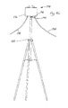
- FIG. 46 is a front elevational view of the portable light assembly shown in FIGS. 43 and 44 top mounted to a tripod and connected by electric cabling to an external power generator,
- FIG. 47 is a bottom perspective view of the portable light assembly shown in FIG. 46 about to be mounted on a mounting table of the tripod, and about to be connected by electric cabling to an external power generator,
- FIG. 48 is a front elevational view of two of the portable light assemblies shown in FIGS. 43 and 44 top mounted to respective tripods and connected by electric cabling to an external power generator,
- FIG. 49 is a front perspective view of a carry case for storing four of the portable light assemblies shown in FIGS. 43 and 44 and four of the tripods shown in FIG. 46 ,
- FIG. 50 is a front perspective view of a portable light assembly according to a third preferred embodiment of the invention when in a closed position, the assembly adapted to be connected directly to an internal battery housed within the assembly,
- FIG. 51 is an exploded front perspective view of the assembly shown in FIG. 50 .
- FIG. 52 is an exploded front perspective view of a portable light assembly according to a fourth preferred embodiment of the invention.
- the portable light assembly 10 is shown in FIGS. 1 and 2 in a closed position, and in FIGS. 3 to 9 in an open position.
- FIGS. 1 and 2 show a closed protective container 12 and a handle 14 for the container. There is shown, when the protective container 12 is closed, a body 16 comprising a hood 17 and a pedestal 18 , a lid 20 , and a rotation switch knob 22 . At the rear of the protective container 12 is a door panel 24 for enclosing a battery 25 (shown in FIG. 16 ) housed in the assembly 10 .
- FIGS. 3 to 9 show an opened protective container 12 in which a light head 26 and attached swivel bracket 28 , together with a handle extension 30 have been withdrawn from the body 16 , along with the raising of the lid 20 and the rotation switch knob 22 .
- the handle extension 30 has a plurality of opposed telescopic posts 32 that can slide reciprocatingly through a bore 33 formed in respective guides 34 located at opposed sides of the body 16 .
- a button 36 when pressed, inactivates or releases a sprung catch mechanism 37 and allows the handle extension 30 to be slid upwardly by lifting the handle 14 (see FIG. 15 ).
- An extendable electrical cable 40 supplies power from the battery to light tubes 42 (see FIGS. 11 and 12 ) located inside the light head.
- the battery is specifically housed within a compartment 44 of the pedestal 18 , the compartment being closed to the outside by the door panel 24 (see also FIGS. 16 and 17 ).
- the light from the light tubes 42 in the light head 26 can be transmitted in a desired horizontal direction by rotating the switch knob 22 about a vertical axis, thereby rotating the swivel bracket 28 and light head 26 about the same vertical axis (see FIGS. 6 and 7 ).
- the light from the light tubes 42 can be transmitted in a desired vertical direction by rotating the light head 26 about a horizontal axis defined by opposed pin assemblies 46 that hold the light head to the swivel bracket 28 (see FIGS. 8 and 9 ).
- FIGS. 10 to 13 show the light head 26 and attached swivel bracket 28 in isolation.
- the rotation switch knob 22 is secured to the swivel bracket 28 and has a neck portion 48 that can be fitted within an aperture 50 defined in the lid 20 (see FIG. 14 ), and a head portion 52 that can be located above the aperture so as to be rotatable by a user.
- the light head 26 has a light mask 54 made of glass steel, and houses four light tubes 42 held in place by brackets 56 at opposed sides of the light head 26 . There is a pair of on/off switches 58 for controlling the supply of battery power to the light tubes 42 on each side. Light reflection brackets 64 are located behind each light tube 42 . There is a charger 66 for the light tubes 42 located centrally in the light head 26 , and a battery power access hole 68 for the electrical cable 40 to connect the charger 66 to the battery. There is also an external power access hole 70 for an electrical cable to connect the charger to an external power source if the battery is dead. The base 72 of the light head 26 is weighted with a ballast material to ensure that it does not flip over.
- FIG. 18 shows the hood 17 of the body 16
- FIG. 19 shows the pedestal 18 of the body 16
- the hood 17 is formed with a cut-out portion 76 to align with an opening 78 of the compartment 44 of the pedestal 18
- the compartment 44 has raised ribbing 80 along its inner surfaces to limit heat transfer between the battery and those surfaces.
- FIG. 20 shows a screw mounting arrangement 82 at the underside of the pedestal.
- the arrangement 82 is adapted to screwably receive wing nuts or adjustable bolts.
- FIG. 21 shows a mounting plate 84 arranged within a mounting slot 86 (see FIG. 19 ) formed in the pedestal 18 .
- the mounting plate 84 is used to side mount the assembly 10 to an elevated horizontal location.
- FIG. 22 shows a mounting plate 88 engaged within a mounting slot 90 (see FIG. 19 ) formed in the pedestal 18 .
- the mounting plate 88 is used to rear mount the assembly 10 to an elevated horizontal location. Side mounting the assembly 10 with the plate 88 is also possible.
- FIG. 23 shows a wall mounting bracket 92 (see isolated bracket 92 in FIG. 25 ) engaged by bolts 94 to a wall 96 and by wing nuts 98 to the screw mounting arrangement 82 at the underside of the pedestal 18 .
- the assembly 10 is rear mounted to the wall 96 .
- the wing nuts 98 allow for a quick manual action without the need for tools to, say, unscrew bolts.
- FIG. 24 shows the same wall mounting bracket 92 used to side mount the assembly 10 to the wall 96 .
- the mounting clamp 100 shown isolated in FIGS. 26 to 29 has a top mount plate 102 supported on a base 104 .
- the base 104 extends upwardly from a top clamp arm 106 which cooperates with a bottom clamp arm 108 .
- the top and bottom clamp arms 106 , 108 are connected by a hinge assembly 110 .
- the top mount plate 102 has four mount holes 114 which are adapted to receive bolts or wing nuts 116 (see FIG. 30 ).
- the location of the wing nuts 116 corresponds to the screw mounting arrangement 82 at the underside of the pedestal 18 so that the wing nuts 116 can engage that arrangement 82 and so top mount the assembly 10 to the mounting clamp 100 (see FIGS. 31 and 32 ) in either a front on or sideways direction.
- the adjustable mounting bracket 118 shown isolated in FIGS. 33 and 34 has a top surface 120 defined by a cross arm 122 that is integrally connected to a side arm 124 . There are four mount holes 126 formed in respective projections 128 from the top surface 120 .
- a slide handle 130 has a carriage 132 that can slide vertically along a toothed track 134 formed on the side arm 124 .
- the variable clamping device 138 has a ratcheted rod 140 that slidably engages a toothed surface within an upright portion 142 of a clamping square 144 .
- the adjustable mounting bracket 118 is able to receive a square cornered, horizontally extending component 151 of various dimensions of, say, a working pole in the space between the arms 122 , 124 and the variable clamping device 138 .
- the mount holes 126 are adapted to receive bolts 152 (see FIG. 35 ).
- the location of the bolts 152 corresponds to the screw mounting arrangement 82 at the underside of the pedestal 18 so that the bolts 152 can engage that arrangement 82 and so top mount the assembly 10 to the mounting bracket 118 (see FIGS. 36 and 37 ) in either a front on or sideways direction.
- FIGS. 38 and 39 show the assembly 10 mounted on a telegraph pole 154 with the use of the mounting bracket 118 .
- the work basket mounting bracket 156 shown isolated in FIG. 40 has a top mount panel 158 , a short side panel 160 and a longer central panel 162 extending downwardly from the top mount panel 158 .
- the location of the wing nuts 168 corresponds to the screw mounting arrangement 82 at the underside of the pedestal 18 so that the wing nuts 168 can engage that arrangement and so top mount the assembly 10 to the mounting bracket 156 .
- the mounting bracket 156 can engage a square cornered rim 170 of a work basket 172 by fitting the rim 170 between the side and central panels 160 , 162 (see FIG. 42 ).
- the portable light assembly 174 shown in FIGS. 43 and 44 has a light head 176 and a handle 178 .
- the arrangement inside the light head 176 is similar to that inside the light head 26 described earlier.
- Through the base 182 is a pair of internal power access holes 184 for respective electrical cables to supply power to the light tubes.
- a central hole 186 is used for mounting the assembly 174 to a tripod 188 (see FIGS. 46 to 48 ).
- FIG. 45 shows six of the assemblies 174 mounted to scaffolding 190 with the use of mounting rings 192 .
- Electrical cables 194 supply internal power to the light tubes inside each of the assemblies 174 .
- the tripods 188 shown in FIGS. 46 to 48 are of a conventional structure but include an upper mounting table 195 with a mounting hole through which a bolt 196 can be received for engaging the central hole 186 of the light head 176 .
- Top mounting the assembly 174 to ground supported tripods 188 enables a wide area of ground to be illuminated with power supplied by an external power generator.
- the portable light assembly 200 shown in FIGS. 50 and 51 is similar to the portable light assembly 10 , but does not include or require a rotation switch knob on the lid, nor an aperture in the lid through which the rotation switch knob can be fitted.
- the light tubes 42 are located in the light head 26 .
- the portable light assembly 210 shown in FIG. 52 differs from the portable light assembly 200 only in that it has light emitting diodes (LEDs) 212 located on boards 214 in the light head 26 .
- the electronic connections with the LEDs 212 are, of course, different to those with the light tubes 42 .
- the assembly has an IP rating of 65 which allows it to be operated in all weather conditions, and has UV protective properties to prevent early structural deterioration, especially of the hood or casing.
Abstract
A portable light assembly (200) has a light head (26) adapted to be housed in a protective container (12) and to be withdrawn therefrom when required for use. The light head (26) is attached to a swivel bracket (28) and is connected to a battery (25) also housed in the container. The portable light assembly includes mounting means (18) for supporting the light head (26) at locations in need of illumination. A handle (14) is connected to a lid (20) of the assembly, and the handle has a release member (36) for releasing an extension post arrangement (30, 32) from the protective container. This allows the extension post arrangement (30, 32), Nd (20), swivel bracket (28) and light head (26) to be slid upwardly by activating the release member (36) and lifting the handle (14).
Description
The present invention relates to portable lighting. In one particular aspect, the invention relates to a portable light assembly that has a light head which is housed in a protective container when not in use and can be withdrawn from the container when required for use whilst maintaining power connection to a battery also housed in the container. In another particular aspect, the invention relates to a portable light assembly that has a light head which may also be connected to an external power generator or other external source of direct power and can be supported by various mounting assemblies at desired locations in need of illumination.
There are many worksites where work is conducted at night or in poorly illuminated areas, and that therefore require suitable lighting. In many cases, the worksites, such as those relating to construction, mining, recreational or emergency services, need one or more lights to be located in areas that provide the widest possible range of illumination. The lighting required to meet these needs must be portable, easy to transport, powerful and robust. It would also be desirable for such lighting to be readily adapted for mounting to various locations.
It is an object of the present invention to overcome, or at least substantially ameliorate, the disadvantages and shortcomings of the prior art, or at least provide a useful alternative.
According to the present invention, there is provided a portable light assembly comprising a light head adapted to be housed in a protective container and to be withdrawn therefrom when required for use, the light head adapted to be connected to a battery also housed in the container, the portable light assembly including mounting means for supporting the light head at locations in need of illumination.
Preferably, the mounting means includes a screw mounting arrangement formed at the underside of the portable light assembly.
It is preferred that the mounting means further includes any one of a mounting plate, mounting bracket, mounting clamp and mounting ring.
In order that the invention may be more readily understood and put into practical effect, reference will now be made to the accompanying drawings, in which:—
The portable light assembly 10 is shown in FIGS. 1 and 2 in a closed position, and in FIGS. 3 to 9 in an open position.
The light from the light tubes 42 in the light head 26 can be transmitted in a desired horizontal direction by rotating the switch knob 22 about a vertical axis, thereby rotating the swivel bracket 28 and light head 26 about the same vertical axis (see FIGS. 6 and 7 ).
The light from the light tubes 42 can be transmitted in a desired vertical direction by rotating the light head 26 about a horizontal axis defined by opposed pin assemblies 46 that hold the light head to the swivel bracket 28 (see FIGS. 8 and 9 ).
The mounting clamp 100 shown isolated in FIGS. 26 to 29 has a top mount plate 102 supported on a base 104. The base 104 extends upwardly from a top clamp arm 106 which cooperates with a bottom clamp arm 108. The top and bottom clamp arms 106, 108 are connected by a hinge assembly 110. There is an adjustable closure assembly 112 which may control the tightness of the closure of the clamp arms 106, 108 around, say, cylindrical, horizontally extending, components 113 of scaffolding or working poles used in the power industry. The top mount plate 102 has four mount holes 114 which are adapted to receive bolts or wing nuts 116 (see FIG. 30 ). The location of the wing nuts 116 corresponds to the screw mounting arrangement 82 at the underside of the pedestal 18 so that the wing nuts 116 can engage that arrangement 82 and so top mount the assembly 10 to the mounting clamp 100 (see FIGS. 31 and 32 ) in either a front on or sideways direction.
The adjustable mounting bracket 118 shown isolated in FIGS. 33 and 34 has a top surface 120 defined by a cross arm 122 that is integrally connected to a side arm 124. There are four mount holes 126 formed in respective projections 128 from the top surface 120. A slide handle 130 has a carriage 132 that can slide vertically along a toothed track 134 formed on the side arm 124. There is a hand grip 136 at one end of the slide handle 130 and a variable clamping device 138 at the other end. The variable clamping device 138 has a ratcheted rod 140 that slidably engages a toothed surface within an upright portion 142 of a clamping square 144. There is an adjustment knob 146 at a lower end of the rod 140 and a carriage 148 at the upper end, the carriage 148 being slidable horizontally along a slotted track 150 supported beneath the cross arm 122. The adjustable mounting bracket 118 is able to receive a square cornered, horizontally extending component 151 of various dimensions of, say, a working pole in the space between the arms 122, 124 and the variable clamping device 138. The mount holes 126 are adapted to receive bolts 152 (see FIG. 35 ). The location of the bolts 152 corresponds to the screw mounting arrangement 82 at the underside of the pedestal 18 so that the bolts 152 can engage that arrangement 82 and so top mount the assembly 10 to the mounting bracket 118 (see FIGS. 36 and 37 ) in either a front on or sideways direction. FIGS. 38 and 39 show the assembly 10 mounted on a telegraph pole 154 with the use of the mounting bracket 118.
The work basket mounting bracket 156 shown isolated in FIG. 40 has a top mount panel 158, a short side panel 160 and a longer central panel 162 extending downwardly from the top mount panel 158. There are four top mount holes 164 formed in respective protrusions 166 from the top mount panel 158, the mount holes 164 being adapted to receive bolts or wing nuts 168 (see FIG. 41 ). The location of the wing nuts 168 corresponds to the screw mounting arrangement 82 at the underside of the pedestal 18 so that the wing nuts 168 can engage that arrangement and so top mount the assembly 10 to the mounting bracket 156. The mounting bracket 156 can engage a square cornered rim 170 of a work basket 172 by fitting the rim 170 between the side and central panels 160, 162 (see FIG. 42 ).
The portable light assembly 174 shown in FIGS. 43 and 44 has a light head 176 and a handle 178. There is a pair of on/off buttons 180 for operating the light tubes located inside the light head 176. The arrangement inside the light head 176 is similar to that inside the light head 26 described earlier. Through the base 182 is a pair of internal power access holes 184 for respective electrical cables to supply power to the light tubes. A central hole 186 is used for mounting the assembly 174 to a tripod 188 (see FIGS. 46 to 48 ).
The tripods 188 shown in FIGS. 46 to 48 are of a conventional structure but include an upper mounting table 195 with a mounting hole through which a bolt 196 can be received for engaging the central hole 186 of the light head 176. Top mounting the assembly 174 to ground supported tripods 188 enables a wide area of ground to be illuminated with power supplied by an external power generator.
Four of the assemblies 174 and four of the tripods 188 may be stored in a carry case 198 shown in FIG. 49 .
The portable light assembly 200 shown in FIGS. 50 and 51 is similar to the portable light assembly 10, but does not include or require a rotation switch knob on the lid, nor an aperture in the lid through which the rotation switch knob can be fitted.
Otherwise, features of the portable light assembly 200 that are similar to features in the assembly 10 are identified by like numerals in FIGS. 50 and 51 .
In this embodiment, the light tubes 42 are located in the light head 26.
The portable light assembly 210 shown in FIG. 52 differs from the portable light assembly 200 only in that it has light emitting diodes (LEDs) 212 located on boards 214 in the light head 26. The electronic connections with the LEDs 212 are, of course, different to those with the light tubes 42.
In general, the assembly has an IP rating of 65 which allows it to be operated in all weather conditions, and has UV protective properties to prevent early structural deterioration, especially of the hood or casing.
It will be apparent to persons skilled in the art that various modifications may be made in details of design and construction of the portable light assembly described above without departing from the scope or ambit of the present invention.
Claims (17)
1. The portable light assembly comprising a light head adapted to be housed in a protective container and to be withdrawn therefrom when required for use, and a lid for closing the protective container, the light head being adapted to be connected to a battery also housed in the container, the portable light assembly including mounting means for supporting the light head at locations in need of illumination, wherein the light head is attached to the lid via a swivel bracket such that when the light head is withdrawn from the protective container the light head can rotate relative to the swivel bracket, the portable light assembly further including a handle extension that is withdrawn from the protective container when the light head is withdrawn, wherein the handle extension is attached to the lid, and the lid supports the swivel bracket, the handle extension having telescopic posts that can slide upwardly from the protective container and wherein a handle is connected to the lid, and the handle includes a means for releasing the handle extension from the protective container, whereby the handle extension, lid, swivel bracket and light head can be slid upwardly by activating the releasing means and lifting the handle.
2. The portable light assembly of claim 1 wherein the mounting means includes a screw mounting arrangement formed at the underside of the portable light assembly.
3. The portable light assembly of claim 1 wherein the mounting means further includes any one of a mounting plate, mounting bracket, mounting clamp and mounting ring.
4. The portable light assembly of claim 1 and further including an extendable electrical cable for supplying power from the battery to a light source inside the light head.
5. A portable light assembly comprising a light head adapted to be housed in a protective container and to be withdrawn therefrom when required for use, the light head being adapted to be connected to a battery also housed within the container, the portable light assembly including mounting means for supporting the light head at locations in need of illumination, wherein the mounting means is a base of the container on which the portable light assembly can stand and is adapted for releasable connection to at least one additional mounting, a lid for closing the protective container, a swivel mounting for attaching the light head to the lid such that when the light head is withdrawn from the protected container the light head can swivel relative to the lid, support posts telescopically mounted from the protective container and connected to the lid to guide and support the lid from a lowered position in which it closes the container with the light head enclosed therein and a raised position in which the light head is withdrawn from the container, a handle connected to the lid, releasable locking means for locking the lid and components attached thereto in the lowered position in which the lid closes the protective container, and release means for releasing the locking means whereby the lid can be drawn to its raised position by means of the handle to thereby withdraw the light head from the protective container when required for use.
6. A portable light assembly, comprising a protective container having a body and a lid for closing the container, a light head adapted to be housed within the closed protective container in a stored condition and to be withdrawn therefrom by opening the lid when required for use, the lid carrying the light head via a swivel mounting, a battery housed in the body of the container for powering the light head, and the container including mounting means for mounting the container at locations in need of illumination, wherein the mounting means is at a lower end of the container, the mounting means being a base on which the portable light assembly can stand and being adapted for releasable connection to at least one additional mounting, wherein the swivel mounting comprises a swivel bracket to which the light head is attached such that when the light head is withdrawn from the protective container by opening the lid, the light head can rotate relative to the swivel bracket about a substantially horizontal axis and the swivel bracket can rotate relative to the lid about a substantially vertical axis.
7. A portable light assembly, comprising a protective container having a body and a lid for closing the container, a light head adapted to be housed within the closed protective container in a stored condition and to be withdrawn therefrom by opening the lid when required for use, the lid carrying the light head via a swivel mounting, a battery housed in the body of the container for powering the light head, and the container including mounting means for mounting the container at locations in need of illumination, wherein the mounting means is at a lower end of the container, the mounting means being a base on which the portable light assembly can stand and being adapted for releasable connection to at least one additional mounting, wherein the lid includes a handle by which the lid with attached light head can be raised from the container body, the container further comprising means for guiding the lid for linear movement relative to the container body in a substantially vertical direction.
8. A portable light assembly according to claim 7 , wherein the additional mounting comprises a tripod.
9. A portable light assembly according to claim 7 , wherein the additional mounting comprises an adjustable mounting bracket.
10. A portable light assembly according to claim 7 , wherein the additional mounting comprises a clamp for connection to scaffolding or a pole.
11. A portable light assembly according to claim 7 , wherein the mounting means includes a screw mounting arrangement formed at the underside of the container.
12. A portable light assembly according to claim 11 , wherein the mounting means further includes any one of a mounting plate, mounting bracket, mounting clamp and mounting ring.
13. A portable light assembly according to claim 7 , wherein the guide means comprises posts attached to the lid and slidable telescopically relative to the body of the container.
14. A portable light assembly according to claim 13 further comprising locking means for retaining the lid in its closed position, the handle including release means actuable to release the locking means to permit the lid with light head to be raised into the condition for use.
15. A portable light assembly according to claim 7 further including an extendible electrical cable for supplying power from the battery to a light source inside the light head.
16. A portable light assembly according to claim 7 , wherein the light source is a plurality of light tubes.
17. A portable light assembly according to claim 7 , wherein the light source is a plurality of light emitting diodes.
Applications Claiming Priority (3)
| Application Number | Priority Date | Filing Date | Title |
|---|---|---|---|
| AU2008904852 | 2008-09-18 | ||
| AU2008904852A AU2008904852A0 (en) | 2008-09-18 | Portable light assembly | |
| PCT/AU2009/001226 WO2010031121A1 (en) | 2008-09-18 | 2009-09-17 | Portable light assembly |
Publications (2)
| Publication Number | Publication Date |
|---|---|
| US20110211340A1 US20110211340A1 (en) | 2011-09-01 |
| US8419207B2 true US8419207B2 (en) | 2013-04-16 |
Family
ID=42039010
Family Applications (1)
| Application Number | Title | Priority Date | Filing Date |
|---|---|---|---|
| US13/119,537 Active 2029-10-21 US8419207B2 (en) | 2008-09-18 | 2009-09-17 | Portable light assembly |
Country Status (16)
| Country | Link |
|---|---|
| US (1) | US8419207B2 (en) |
| EP (1) | EP2350521B1 (en) |
| JP (1) | JP5389927B2 (en) |
| KR (1) | KR101496731B1 (en) |
| CN (1) | CN102216670B (en) |
| AU (1) | AU2009295263B2 (en) |
| BR (1) | BRPI0919233B1 (en) |
| CA (1) | CA2774085C (en) |
| ES (1) | ES2545108T3 (en) |
| HK (1) | HK1163226A1 (en) |
| MY (1) | MY154280A (en) |
| NZ (1) | NZ592148A (en) |
| PL (1) | PL2350521T3 (en) |
| RU (1) | RU2499182C2 (en) |
| WO (1) | WO2010031121A1 (en) |
| ZA (1) | ZA201102755B (en) |
Cited By (2)
| Publication number | Priority date | Publication date | Assignee | Title |
|---|---|---|---|---|
| US20150009660A1 (en) * | 2013-07-03 | 2015-01-08 | Wen-Sung Lee | Collapsible Camping Lantern |
| US10493901B2 (en) | 2017-09-25 | 2019-12-03 | Milwaukee Electric Tool Corporation | Light assembly for attachment to a surface of a vehicle |
Families Citing this family (8)
| Publication number | Priority date | Publication date | Assignee | Title |
|---|---|---|---|---|
| US9976724B2 (en) | 2012-06-11 | 2018-05-22 | Energizer Brands, Llc | Lighting device construction |
| US9845940B2 (en) | 2012-06-11 | 2017-12-19 | Energizer Brands, Llc | Lighting device and light panel construction |
| CN103256488A (en) * | 2013-04-26 | 2013-08-21 | 河南省电力公司信阳供电公司 | Flashlight |
| US10378739B2 (en) | 2015-04-24 | 2019-08-13 | Milwaukee Electric Tool Corporation | Stand light |
| CN108006534A (en) * | 2017-11-03 | 2018-05-08 | 姚宝佳 | A kind of repeatable municipal road lamp and handler to fly a national flag of quick connection |
| FR3091918B1 (en) * | 2019-01-23 | 2021-09-10 | Zedel | Compact headlamp with a swivel plate |
| US11293619B2 (en) * | 2019-10-08 | 2022-04-05 | Valeo Vision | Light system, method of forming tunnels of light, a mobile 360° light system, and a method of cleaning the mobile 360° light system |
| CN114440172B (en) * | 2022-01-17 | 2022-11-04 | 深圳市联域光电股份有限公司 | Lighting lamp |
Citations (21)
| Publication number | Priority date | Publication date | Assignee | Title |
|---|---|---|---|---|
| US2612598A (en) * | 1950-10-17 | 1952-09-30 | Berman Frank | Flashlight with h-shaped frame forming opposed holders for dry cells and lamp head |
| US3944806A (en) * | 1973-07-30 | 1976-03-16 | The Commonwealth Of Australia | Portable high intensity lamp |
| US4290093A (en) | 1980-03-20 | 1981-09-15 | Lite-A-Guide, Inc. | Portable illuminated magazine case |
| US4586114A (en) * | 1984-10-12 | 1986-04-29 | Riley N D | Night-hunting method and apparatus |
| DE3641908A1 (en) | 1986-12-08 | 1988-06-09 | Hugo Winderlich | Self-activating, re-chargeable flashing warning light for breakdowns |
| US5012394A (en) * | 1988-11-15 | 1991-04-30 | Woodward John G | Hand portable light with extendable lamp housing |
| US5169226A (en) | 1992-05-04 | 1992-12-08 | Friedman Arthur S | Portable desk light |
| GB2305718A (en) | 1995-09-27 | 1997-04-16 | Fee Tat Holdings Hk Limited | Lamp with sliding reflector |
| US5630660A (en) * | 1996-05-16 | 1997-05-20 | Chen; Wei-Fu | Warning light |
| US5758949A (en) * | 1997-02-26 | 1998-06-02 | The Coleman Company, Inc. | Collapsible lantern |
| FR2770615A1 (en) | 1997-11-03 | 1999-05-07 | Marie France Molle | Portable lamp for communal events, such as celebration, religious or otherwise. |
| US6305820B1 (en) * | 2000-02-13 | 2001-10-23 | Tupor Limited | Telescopic lantern |
| JP2004071318A (en) | 2002-08-06 | 2004-03-04 | Masao Shirasaka | Portable lighting device |
| US20040052073A1 (en) * | 2002-09-16 | 2004-03-18 | Chia-Ching Chang | Flashlight assembly |
| US6986590B1 (en) | 2002-09-04 | 2006-01-17 | Padden Stephen J | Articulated light |
| US7063444B2 (en) * | 2004-02-17 | 2006-06-20 | Eml Technologies Llc | Omni-directional worklight |
| RU57935U1 (en) | 2005-10-24 | 2006-10-27 | Общество с ограниченной ответственностью "УралТехИс" | PORTABLE MINING INDUSTRIAL USE |
| US20070159817A1 (en) * | 2006-01-10 | 2007-07-12 | Evans Donald F | Yard sign illuminating device and system |
| EP1921273A1 (en) | 2006-11-07 | 2008-05-14 | Snecma | Device for attaching a turbine nozzle, turbine comprising said device, and aircraft engine equipped with said device |
| US7850329B2 (en) * | 2008-05-06 | 2010-12-14 | Blackbeam, Llc | Flashlight with integrated clamp handle |
| US7871177B1 (en) * | 2007-11-01 | 2011-01-18 | Neville Blake Hanchett | Light mounting apparatus |
Family Cites Families (21)
| Publication number | Priority date | Publication date | Assignee | Title |
|---|---|---|---|---|
| US2612588A (en) | 1950-02-07 | 1952-09-30 | Walter F Schilling | Cigarette lighter |
| JPH067533Y2 (en) * | 1988-02-10 | 1994-02-23 | 昌 荒井 | Lighting equipment support equipment |
| JPH0339201U (en) * | 1990-04-26 | 1991-04-16 | ||
| SU1756734A1 (en) * | 1990-09-11 | 1992-08-23 | Центральный научно-исследовательский радиотехнический институт | Lantern |
| JPH04337201A (en) * | 1991-05-15 | 1992-11-25 | Matsushita Electric Works Ltd | Movable type illumination apparatus |
| JPH05101702A (en) * | 1991-10-08 | 1993-04-23 | Sony Corp | Lighting device |
| JPH0560942U (en) * | 1992-01-13 | 1993-08-10 | 有限会社斎藤興産 | Lighting for night work installed in the cab of construction machinery |
| CH686640A5 (en) * | 1993-12-28 | 1996-05-15 | Miratron Ag | Battery-operated warning lamp for towed farm machinery and parked heavy plant. |
| JP3671499B2 (en) * | 1996-02-15 | 2005-07-13 | 松下電工株式会社 | Lighting device |
| JPH10228801A (en) * | 1997-02-12 | 1998-08-25 | Seizo Tanabe | Lift-up type lantern |
| CN2366679Y (en) * | 1999-03-08 | 2000-03-01 | 飞龙发展有限公司 | Telescopic type lighting lamp |
| JP2001110201A (en) * | 1999-10-12 | 2001-04-20 | Takashi Iino | Flashlight with stand |
| JP2002355770A (en) * | 2001-05-31 | 2002-12-10 | Kaneko Seisakusho:Kk | Light device attached to electric rotation tool |
| HK1039252A2 (en) * | 2001-08-24 | 2002-03-28 | Flying Dragon Electrical Appli | Remote control hand lantern |
| US7578598B2 (en) * | 2006-11-13 | 2009-08-25 | Black & Decker Inc. | Battery charging work light |
| US7021788B2 (en) * | 2004-06-02 | 2006-04-04 | Tupor Limited | Telescopic lantern |
| JP2007134175A (en) * | 2005-11-10 | 2007-05-31 | Chugoku Electric Power Co Inc:The | Lighting device for work and its supporting fixture |
| US7311418B2 (en) * | 2006-05-16 | 2007-12-25 | Zelco Industries Inc. | Booklight with retractable clip and light |
| RU59774U1 (en) * | 2006-08-21 | 2006-12-27 | Александр Григорьевич Булатов | LIGHTING INSTALLATION "LIGHT BALL" |
| US7470036B2 (en) * | 2007-03-28 | 2008-12-30 | Pelican Products, Inc. | Lighting system |
| JP3139851U (en) * | 2007-12-11 | 2008-03-06 | 呉祖耀 | LED light |
-
2009
- 2009-09-17 CN CN200980146064XA patent/CN102216670B/en not_active Expired - Fee Related
- 2009-09-17 NZ NZ592148A patent/NZ592148A/en not_active IP Right Cessation
- 2009-09-17 MY MYPI2011001184A patent/MY154280A/en unknown
- 2009-09-17 JP JP2011527152A patent/JP5389927B2/en not_active Expired - Fee Related
- 2009-09-17 KR KR1020117008774A patent/KR101496731B1/en active IP Right Grant
- 2009-09-17 RU RU2011115133/07A patent/RU2499182C2/en active
- 2009-09-17 ES ES09813888.6T patent/ES2545108T3/en active Active
- 2009-09-17 CA CA2774085A patent/CA2774085C/en active Active
- 2009-09-17 EP EP09813888.6A patent/EP2350521B1/en not_active Not-in-force
- 2009-09-17 PL PL09813888T patent/PL2350521T3/en unknown
- 2009-09-17 AU AU2009295263A patent/AU2009295263B2/en not_active Ceased
- 2009-09-17 WO PCT/AU2009/001226 patent/WO2010031121A1/en active Application Filing
- 2009-09-17 BR BRPI0919233A patent/BRPI0919233B1/en not_active IP Right Cessation
- 2009-09-17 US US13/119,537 patent/US8419207B2/en active Active
-
2011
- 2011-04-13 ZA ZA2011/02755A patent/ZA201102755B/en unknown
-
2012
- 2012-04-10 HK HK12103489.8A patent/HK1163226A1/en not_active IP Right Cessation
Patent Citations (21)
| Publication number | Priority date | Publication date | Assignee | Title |
|---|---|---|---|---|
| US2612598A (en) * | 1950-10-17 | 1952-09-30 | Berman Frank | Flashlight with h-shaped frame forming opposed holders for dry cells and lamp head |
| US3944806A (en) * | 1973-07-30 | 1976-03-16 | The Commonwealth Of Australia | Portable high intensity lamp |
| US4290093A (en) | 1980-03-20 | 1981-09-15 | Lite-A-Guide, Inc. | Portable illuminated magazine case |
| US4586114A (en) * | 1984-10-12 | 1986-04-29 | Riley N D | Night-hunting method and apparatus |
| DE3641908A1 (en) | 1986-12-08 | 1988-06-09 | Hugo Winderlich | Self-activating, re-chargeable flashing warning light for breakdowns |
| US5012394A (en) * | 1988-11-15 | 1991-04-30 | Woodward John G | Hand portable light with extendable lamp housing |
| US5169226A (en) | 1992-05-04 | 1992-12-08 | Friedman Arthur S | Portable desk light |
| GB2305718A (en) | 1995-09-27 | 1997-04-16 | Fee Tat Holdings Hk Limited | Lamp with sliding reflector |
| US5630660A (en) * | 1996-05-16 | 1997-05-20 | Chen; Wei-Fu | Warning light |
| US5758949A (en) * | 1997-02-26 | 1998-06-02 | The Coleman Company, Inc. | Collapsible lantern |
| FR2770615A1 (en) | 1997-11-03 | 1999-05-07 | Marie France Molle | Portable lamp for communal events, such as celebration, religious or otherwise. |
| US6305820B1 (en) * | 2000-02-13 | 2001-10-23 | Tupor Limited | Telescopic lantern |
| JP2004071318A (en) | 2002-08-06 | 2004-03-04 | Masao Shirasaka | Portable lighting device |
| US6986590B1 (en) | 2002-09-04 | 2006-01-17 | Padden Stephen J | Articulated light |
| US20040052073A1 (en) * | 2002-09-16 | 2004-03-18 | Chia-Ching Chang | Flashlight assembly |
| US7063444B2 (en) * | 2004-02-17 | 2006-06-20 | Eml Technologies Llc | Omni-directional worklight |
| RU57935U1 (en) | 2005-10-24 | 2006-10-27 | Общество с ограниченной ответственностью "УралТехИс" | PORTABLE MINING INDUSTRIAL USE |
| US20070159817A1 (en) * | 2006-01-10 | 2007-07-12 | Evans Donald F | Yard sign illuminating device and system |
| EP1921273A1 (en) | 2006-11-07 | 2008-05-14 | Snecma | Device for attaching a turbine nozzle, turbine comprising said device, and aircraft engine equipped with said device |
| US7871177B1 (en) * | 2007-11-01 | 2011-01-18 | Neville Blake Hanchett | Light mounting apparatus |
| US7850329B2 (en) * | 2008-05-06 | 2010-12-14 | Blackbeam, Llc | Flashlight with integrated clamp handle |
Non-Patent Citations (1)
| Title |
|---|
| International Search Report dated Nov. 26, 2009. |
Cited By (6)
| Publication number | Priority date | Publication date | Assignee | Title |
|---|---|---|---|---|
| US20150009660A1 (en) * | 2013-07-03 | 2015-01-08 | Wen-Sung Lee | Collapsible Camping Lantern |
| US8939601B1 (en) * | 2013-07-03 | 2015-01-27 | Wen-Sung Lee | Collapsible camping lantern |
| US10493901B2 (en) | 2017-09-25 | 2019-12-03 | Milwaukee Electric Tool Corporation | Light assembly for attachment to a surface of a vehicle |
| US10744928B2 (en) | 2017-09-25 | 2020-08-18 | Milwaukee Electric Tool Corporation | Light assembly for attachment to a surface of a vehicle |
| US11299087B2 (en) | 2017-09-25 | 2022-04-12 | Milwaukee Electric Tool Corporation | Light assembly for attachment to a surface of a vehicle |
| US11613202B2 (en) | 2017-09-25 | 2023-03-28 | Milwaukee Electric Tool Corporation | Light assembly for attachment to a surface of a vehicle |
Also Published As
| Publication number | Publication date |
|---|---|
| KR20110081818A (en) | 2011-07-14 |
| BRPI0919233B1 (en) | 2019-08-27 |
| CN102216670A (en) | 2011-10-12 |
| EP2350521B1 (en) | 2015-05-13 |
| WO2010031121A9 (en) | 2010-11-25 |
| ZA201102755B (en) | 2011-12-28 |
| AU2009295263B2 (en) | 2014-05-08 |
| BRPI0919233A2 (en) | 2016-09-27 |
| CN102216670B (en) | 2013-07-31 |
| EP2350521A4 (en) | 2014-05-07 |
| AU2009295263A1 (en) | 2010-03-25 |
| CA2774085C (en) | 2015-01-06 |
| EP2350521A1 (en) | 2011-08-03 |
| RU2499182C2 (en) | 2013-11-20 |
| WO2010031121A1 (en) | 2010-03-25 |
| HK1163226A1 (en) | 2012-09-07 |
| US20110211340A1 (en) | 2011-09-01 |
| JP2012503276A (en) | 2012-02-02 |
| JP5389927B2 (en) | 2014-01-15 |
| ES2545108T3 (en) | 2015-09-08 |
| PL2350521T3 (en) | 2015-11-30 |
| RU2011115133A (en) | 2012-10-27 |
| NZ592148A (en) | 2014-01-31 |
| KR101496731B1 (en) | 2015-03-02 |
| CA2774085A1 (en) | 2010-03-25 |
| MY154280A (en) | 2015-05-29 |
Similar Documents
| Publication | Publication Date | Title |
|---|---|---|
| US8419207B2 (en) | Portable light assembly | |
| US8721124B2 (en) | Retractable light assembly | |
| CA2868910C (en) | Collapsible portable stand with telescoping support and integral storage case | |
| KR101590604B1 (en) | The dispaly mounted smart table | |
| US20150103518A1 (en) | Solar lamp with adjustable height | |
| US9834421B2 (en) | System, apparatus, and method for the transport and positioning of a display | |
| WO2005072303A2 (en) | Surveillance apparatus | |
| JP2012503276A5 (en) | ||
| CN107250660A (en) | Adjustable head lamp | |
| EP3473785B1 (en) | Telescopic mast | |
| AU2014208237A1 (en) | Portable light assembly | |
| CN114075920A (en) | Folding ladder for outdoor power supply maintenance in rainy days | |
| CN107388202A (en) | All-directional working lamp | |
| CN213546779U (en) | Laser instrument support of convenient installation | |
| CN214943061U (en) | Safe and reliable's security fence for construction | |
| CN216345870U (en) | Multifunctional garden lamp | |
| CN213513614U (en) | Lifting platform auxiliary lighting device for field construction | |
| CN212008281U (en) | Overhead line defect observer | |
| KR20060031327A (en) | An illuminator | |
| US20220033222A1 (en) | Attic Lift System | |
| WO2022263460A1 (en) | Transportation box and modular equipment assembly | |
| CN114198653A (en) | Multifunctional floodlight working lamp | |
| US7124991B1 (en) | Lighting unit | |
| JP3138723U (en) | Stand type lighting fixture | |
| AU2010202629A1 (en) | A light fitting assembly |
Legal Events
| Date | Code | Title | Description |
|---|---|---|---|
| AS | Assignment |
Owner name: GOLIGHT PTY LIMITED, AUSTRALIA Free format text: ASSIGNMENT OF ASSIGNORS INTEREST;ASSIGNOR:SMITH, GLENN;REEL/FRAME:026359/0734 Effective date: 20110523 |
|
| STCF | Information on status: patent grant |
Free format text: PATENTED CASE |
|
| FPAY | Fee payment |
Year of fee payment: 4 |
|
| MAFP | Maintenance fee payment |
Free format text: PAYMENT OF MAINTENANCE FEE, 8TH YR, SMALL ENTITY (ORIGINAL EVENT CODE: M2552); ENTITY STATUS OF PATENT OWNER: SMALL ENTITY Year of fee payment: 8 |