US8419998B2 - Process for making hollow carbon spheres - Google Patents
Process for making hollow carbon spheres Download PDFInfo
- Publication number
- US8419998B2 US8419998B2 US13/080,738 US201113080738A US8419998B2 US 8419998 B2 US8419998 B2 US 8419998B2 US 201113080738 A US201113080738 A US 201113080738A US 8419998 B2 US8419998 B2 US 8419998B2
- Authority
- US
- United States
- Prior art keywords
- carbon
- hollow carbon
- shell
- sphere
- hollow
- Prior art date
- Legal status (The legal status is an assumption and is not a legal conclusion. Google has not performed a legal analysis and makes no representation as to the accuracy of the status listed.)
- Expired - Fee Related, expires
Links
- OKTJSMMVPCPJKN-UHFFFAOYSA-N Carbon Chemical compound [C] OKTJSMMVPCPJKN-UHFFFAOYSA-N 0.000 title claims abstract description 141
- 229910052799 carbon Inorganic materials 0.000 title claims abstract description 141
- 238000000034 method Methods 0.000 title claims description 23
- 230000008569 process Effects 0.000 title claims description 18
- 239000000463 material Substances 0.000 claims description 49
- 239000011162 core material Substances 0.000 claims description 25
- 238000000151 deposition Methods 0.000 claims description 16
- 230000003197 catalytic effect Effects 0.000 claims description 12
- 238000004090 dissolution Methods 0.000 claims description 9
- 230000002378 acidificating effect Effects 0.000 claims description 5
- 239000011149 active material Substances 0.000 claims description 4
- 238000005229 chemical vapour deposition Methods 0.000 claims description 2
- 238000009833 condensation Methods 0.000 claims description 2
- 230000005494 condensation Effects 0.000 claims description 2
- 238000000608 laser ablation Methods 0.000 claims description 2
- 238000007614 solvation Methods 0.000 claims description 2
- 230000008016 vaporization Effects 0.000 claims description 2
- 238000010891 electric arc Methods 0.000 claims 1
- 239000011257 shell material Substances 0.000 description 48
- 239000002243 precursor Substances 0.000 description 33
- 239000000443 aerosol Substances 0.000 description 31
- 239000007789 gas Substances 0.000 description 31
- 239000002245 particle Substances 0.000 description 18
- 239000002105 nanoparticle Substances 0.000 description 15
- MWPLVEDNUUSJAV-UHFFFAOYSA-N anthracene Chemical compound C1=CC=CC2=CC3=CC=CC=C3C=C21 MWPLVEDNUUSJAV-UHFFFAOYSA-N 0.000 description 12
- VLKZOEOYAKHREP-UHFFFAOYSA-N n-Hexane Chemical compound CCCCCC VLKZOEOYAKHREP-UHFFFAOYSA-N 0.000 description 12
- 239000000843 powder Substances 0.000 description 12
- 239000011258 core-shell material Substances 0.000 description 11
- 230000037361 pathway Effects 0.000 description 11
- ATJFFYVFTNAWJD-UHFFFAOYSA-N Tin Chemical compound [Sn] ATJFFYVFTNAWJD-UHFFFAOYSA-N 0.000 description 10
- 239000007788 liquid Substances 0.000 description 9
- 229910052718 tin Inorganic materials 0.000 description 9
- XKRFYHLGVUSROY-UHFFFAOYSA-N Argon Chemical compound [Ar] XKRFYHLGVUSROY-UHFFFAOYSA-N 0.000 description 8
- 125000004429 atom Chemical group 0.000 description 8
- 239000011263 electroactive material Substances 0.000 description 7
- 238000003917 TEM image Methods 0.000 description 6
- -1 poly(alkylene glycol Chemical compound 0.000 description 6
- 239000000203 mixture Substances 0.000 description 5
- XEEYBQQBJWHFJM-UHFFFAOYSA-N Iron Chemical compound [Fe] XEEYBQQBJWHFJM-UHFFFAOYSA-N 0.000 description 4
- WHXSMMKQMYFTQS-UHFFFAOYSA-N Lithium Chemical compound [Li] WHXSMMKQMYFTQS-UHFFFAOYSA-N 0.000 description 4
- PXHVJJICTQNCMI-UHFFFAOYSA-N Nickel Chemical compound [Ni] PXHVJJICTQNCMI-UHFFFAOYSA-N 0.000 description 4
- KDLHZDBZIXYQEI-UHFFFAOYSA-N Palladium Chemical compound [Pd] KDLHZDBZIXYQEI-UHFFFAOYSA-N 0.000 description 4
- VYPSYNLAJGMNEJ-UHFFFAOYSA-N Silicium dioxide Chemical compound O=[Si]=O VYPSYNLAJGMNEJ-UHFFFAOYSA-N 0.000 description 4
- 229910052786 argon Inorganic materials 0.000 description 4
- 239000003814 drug Substances 0.000 description 4
- 229940079593 drug Drugs 0.000 description 4
- 229910052744 lithium Inorganic materials 0.000 description 4
- BASFCYQUMIYNBI-UHFFFAOYSA-N platinum Chemical compound [Pt] BASFCYQUMIYNBI-UHFFFAOYSA-N 0.000 description 4
- 239000002253 acid Substances 0.000 description 3
- 229910045601 alloy Inorganic materials 0.000 description 3
- 239000000956 alloy Substances 0.000 description 3
- 125000004432 carbon atom Chemical group C* 0.000 description 3
- 239000011852 carbon nanoparticle Substances 0.000 description 3
- 239000000919 ceramic Substances 0.000 description 3
- 239000011261 inert gas Substances 0.000 description 3
- LFQSCWFLJHTTHZ-UHFFFAOYSA-N Ethanol Chemical compound CCO LFQSCWFLJHTTHZ-UHFFFAOYSA-N 0.000 description 2
- 102000008394 Immunoglobulin Fragments Human genes 0.000 description 2
- 108010021625 Immunoglobulin Fragments Proteins 0.000 description 2
- BQCADISMDOOEFD-UHFFFAOYSA-N Silver Chemical compound [Ag] BQCADISMDOOEFD-UHFFFAOYSA-N 0.000 description 2
- 238000005275 alloying Methods 0.000 description 2
- 229910052782 aluminium Inorganic materials 0.000 description 2
- XAGFODPZIPBFFR-UHFFFAOYSA-N aluminium Chemical compound [Al] XAGFODPZIPBFFR-UHFFFAOYSA-N 0.000 description 2
- 229910017052 cobalt Inorganic materials 0.000 description 2
- 239000010941 cobalt Substances 0.000 description 2
- GUTLYIVDDKVIGB-UHFFFAOYSA-N cobalt atom Chemical compound [Co] GUTLYIVDDKVIGB-UHFFFAOYSA-N 0.000 description 2
- 230000008021 deposition Effects 0.000 description 2
- 238000010586 diagram Methods 0.000 description 2
- 238000012377 drug delivery Methods 0.000 description 2
- 230000000694 effects Effects 0.000 description 2
- LYCAIKOWRPUZTN-UHFFFAOYSA-N ethylene glycol Natural products OCCO LYCAIKOWRPUZTN-UHFFFAOYSA-N 0.000 description 2
- PCHJSUWPFVWCPO-UHFFFAOYSA-N gold Chemical compound [Au] PCHJSUWPFVWCPO-UHFFFAOYSA-N 0.000 description 2
- 229910052737 gold Inorganic materials 0.000 description 2
- 239000010931 gold Substances 0.000 description 2
- WGCNASOHLSPBMP-UHFFFAOYSA-N hydroxyacetaldehyde Natural products OCC=O WGCNASOHLSPBMP-UHFFFAOYSA-N 0.000 description 2
- 229910052742 iron Inorganic materials 0.000 description 2
- 229910052759 nickel Inorganic materials 0.000 description 2
- 229910052763 palladium Inorganic materials 0.000 description 2
- 229910052697 platinum Inorganic materials 0.000 description 2
- 239000010453 quartz Substances 0.000 description 2
- 229910052702 rhenium Inorganic materials 0.000 description 2
- WUAPFZMCVAUBPE-UHFFFAOYSA-N rhenium atom Chemical compound [Re] WUAPFZMCVAUBPE-UHFFFAOYSA-N 0.000 description 2
- 229910052703 rhodium Inorganic materials 0.000 description 2
- 239000010948 rhodium Substances 0.000 description 2
- MHOVAHRLVXNVSD-UHFFFAOYSA-N rhodium atom Chemical compound [Rh] MHOVAHRLVXNVSD-UHFFFAOYSA-N 0.000 description 2
- 229910052709 silver Inorganic materials 0.000 description 2
- 239000004332 silver Substances 0.000 description 2
- VZGDMQKNWNREIO-UHFFFAOYSA-N tetrachloromethane Chemical compound ClC(Cl)(Cl)Cl VZGDMQKNWNREIO-UHFFFAOYSA-N 0.000 description 2
- 229920002732 Polyanhydride Polymers 0.000 description 1
- 229920000954 Polyglycolide Polymers 0.000 description 1
- XUIMIQQOPSSXEZ-UHFFFAOYSA-N Silicon Chemical compound [Si] XUIMIQQOPSSXEZ-UHFFFAOYSA-N 0.000 description 1
- HCHKCACWOHOZIP-UHFFFAOYSA-N Zinc Chemical compound [Zn] HCHKCACWOHOZIP-UHFFFAOYSA-N 0.000 description 1
- RQMIWLMVTCKXAQ-UHFFFAOYSA-N [AlH3].[C] Chemical compound [AlH3].[C] RQMIWLMVTCKXAQ-UHFFFAOYSA-N 0.000 description 1
- QWJYDTCSUDMGSU-UHFFFAOYSA-N [Sn].[C] Chemical compound [Sn].[C] QWJYDTCSUDMGSU-UHFFFAOYSA-N 0.000 description 1
- 239000012670 alkaline solution Substances 0.000 description 1
- 239000002246 antineoplastic agent Substances 0.000 description 1
- 229940041181 antineoplastic drug Drugs 0.000 description 1
- 150000001720 carbohydrates Chemical class 0.000 description 1
- 230000015556 catabolic process Effects 0.000 description 1
- 239000011248 coating agent Substances 0.000 description 1
- 238000000576 coating method Methods 0.000 description 1
- 238000013270 controlled release Methods 0.000 description 1
- 238000001816 cooling Methods 0.000 description 1
- 229920001577 copolymer Polymers 0.000 description 1
- 239000013078 crystal Substances 0.000 description 1
- 230000007423 decrease Effects 0.000 description 1
- 238000006731 degradation reaction Methods 0.000 description 1
- 238000009792 diffusion process Methods 0.000 description 1
- 238000011978 dissolution method Methods 0.000 description 1
- 238000009826 distribution Methods 0.000 description 1
- 230000009977 dual effect Effects 0.000 description 1
- 229910052732 germanium Inorganic materials 0.000 description 1
- GNPVGFCGXDBREM-UHFFFAOYSA-N germanium atom Chemical compound [Ge] GNPVGFCGXDBREM-UHFFFAOYSA-N 0.000 description 1
- 150000004676 glycans Chemical class 0.000 description 1
- 229910002804 graphite Inorganic materials 0.000 description 1
- 239000010439 graphite Substances 0.000 description 1
- 238000000227 grinding Methods 0.000 description 1
- 239000001307 helium Substances 0.000 description 1
- 229910052734 helium Inorganic materials 0.000 description 1
- SWQJXJOGLNCZEY-UHFFFAOYSA-N helium atom Chemical compound [He] SWQJXJOGLNCZEY-UHFFFAOYSA-N 0.000 description 1
- 229910010272 inorganic material Inorganic materials 0.000 description 1
- 239000011147 inorganic material Substances 0.000 description 1
- 238000005304 joining Methods 0.000 description 1
- 150000002632 lipids Chemical class 0.000 description 1
- 238000004519 manufacturing process Methods 0.000 description 1
- 239000011159 matrix material Substances 0.000 description 1
- 239000000155 melt Substances 0.000 description 1
- 229910052751 metal Inorganic materials 0.000 description 1
- 239000002184 metal Substances 0.000 description 1
- 230000005012 migration Effects 0.000 description 1
- 238000013508 migration Methods 0.000 description 1
- 238000002156 mixing Methods 0.000 description 1
- 238000012986 modification Methods 0.000 description 1
- 230000004048 modification Effects 0.000 description 1
- 239000002088 nanocapsule Substances 0.000 description 1
- 150000007523 nucleic acids Chemical class 0.000 description 1
- 102000039446 nucleic acids Human genes 0.000 description 1
- 108020004707 nucleic acids Proteins 0.000 description 1
- 239000011368 organic material Substances 0.000 description 1
- 230000001590 oxidative effect Effects 0.000 description 1
- 229920000747 poly(lactic acid) Polymers 0.000 description 1
- 229920001606 poly(lactic acid-co-glycolic acid) Polymers 0.000 description 1
- 229920000642 polymer Polymers 0.000 description 1
- 229920001282 polysaccharide Polymers 0.000 description 1
- 239000005017 polysaccharide Substances 0.000 description 1
- 102000004169 proteins and genes Human genes 0.000 description 1
- 108090000623 proteins and genes Proteins 0.000 description 1
- 230000008707 rearrangement Effects 0.000 description 1
- 230000008521 reorganization Effects 0.000 description 1
- 229910052710 silicon Inorganic materials 0.000 description 1
- 239000010703 silicon Substances 0.000 description 1
- 239000000377 silicon dioxide Substances 0.000 description 1
- 239000007787 solid Substances 0.000 description 1
- 239000000126 substance Substances 0.000 description 1
- 239000000725 suspension Substances 0.000 description 1
- 238000007910 systemic administration Methods 0.000 description 1
- 231100000331 toxic Toxicity 0.000 description 1
- 230000002588 toxic effect Effects 0.000 description 1
- 238000009834 vaporization Methods 0.000 description 1
- 239000011364 vaporized material Substances 0.000 description 1
Images


Classifications
-
- B—PERFORMING OPERATIONS; TRANSPORTING
- B01—PHYSICAL OR CHEMICAL PROCESSES OR APPARATUS IN GENERAL
- B01J—CHEMICAL OR PHYSICAL PROCESSES, e.g. CATALYSIS OR COLLOID CHEMISTRY; THEIR RELEVANT APPARATUS
- B01J21/00—Catalysts comprising the elements, oxides, or hydroxides of magnesium, boron, aluminium, carbon, silicon, titanium, zirconium, or hafnium
- B01J21/18—Carbon
-
- B—PERFORMING OPERATIONS; TRANSPORTING
- B01—PHYSICAL OR CHEMICAL PROCESSES OR APPARATUS IN GENERAL
- B01J—CHEMICAL OR PHYSICAL PROCESSES, e.g. CATALYSIS OR COLLOID CHEMISTRY; THEIR RELEVANT APPARATUS
- B01J13/00—Colloid chemistry, e.g. the production of colloidal materials or their solutions, not otherwise provided for; Making microcapsules or microballoons
- B01J13/02—Making microcapsules or microballoons
- B01J13/04—Making microcapsules or microballoons by physical processes, e.g. drying, spraying
-
- B—PERFORMING OPERATIONS; TRANSPORTING
- B01—PHYSICAL OR CHEMICAL PROCESSES OR APPARATUS IN GENERAL
- B01J—CHEMICAL OR PHYSICAL PROCESSES, e.g. CATALYSIS OR COLLOID CHEMISTRY; THEIR RELEVANT APPARATUS
- B01J23/00—Catalysts comprising metals or metal oxides or hydroxides, not provided for in group B01J21/00
- B01J23/38—Catalysts comprising metals or metal oxides or hydroxides, not provided for in group B01J21/00 of noble metals
- B01J23/40—Catalysts comprising metals or metal oxides or hydroxides, not provided for in group B01J21/00 of noble metals of the platinum group metals
-
- B—PERFORMING OPERATIONS; TRANSPORTING
- B01—PHYSICAL OR CHEMICAL PROCESSES OR APPARATUS IN GENERAL
- B01J—CHEMICAL OR PHYSICAL PROCESSES, e.g. CATALYSIS OR COLLOID CHEMISTRY; THEIR RELEVANT APPARATUS
- B01J23/00—Catalysts comprising metals or metal oxides or hydroxides, not provided for in group B01J21/00
- B01J23/38—Catalysts comprising metals or metal oxides or hydroxides, not provided for in group B01J21/00 of noble metals
- B01J23/48—Silver or gold
-
- B—PERFORMING OPERATIONS; TRANSPORTING
- B01—PHYSICAL OR CHEMICAL PROCESSES OR APPARATUS IN GENERAL
- B01J—CHEMICAL OR PHYSICAL PROCESSES, e.g. CATALYSIS OR COLLOID CHEMISTRY; THEIR RELEVANT APPARATUS
- B01J23/00—Catalysts comprising metals or metal oxides or hydroxides, not provided for in group B01J21/00
- B01J23/70—Catalysts comprising metals or metal oxides or hydroxides, not provided for in group B01J21/00 of the iron group metals or copper
- B01J23/74—Iron group metals
-
- B01J35/51—
-
- B—PERFORMING OPERATIONS; TRANSPORTING
- B01—PHYSICAL OR CHEMICAL PROCESSES OR APPARATUS IN GENERAL
- B01J—CHEMICAL OR PHYSICAL PROCESSES, e.g. CATALYSIS OR COLLOID CHEMISTRY; THEIR RELEVANT APPARATUS
- B01J37/00—Processes, in general, for preparing catalysts; Processes, in general, for activation of catalysts
- B01J37/0009—Use of binding agents; Moulding; Pressing; Powdering; Granulating; Addition of materials ameliorating the mechanical properties of the product catalyst
- B01J37/0018—Addition of a binding agent or of material, later completely removed among others as result of heat treatment, leaching or washing,(e.g. forming of pores; protective layer, desintegrating by heat)
-
- C—CHEMISTRY; METALLURGY
- C01—INORGANIC CHEMISTRY
- C01B—NON-METALLIC ELEMENTS; COMPOUNDS THEREOF; METALLOIDS OR COMPOUNDS THEREOF NOT COVERED BY SUBCLASS C01C
- C01B32/00—Carbon; Compounds thereof
- C01B32/05—Preparation or purification of carbon not covered by groups C01B32/15, C01B32/20, C01B32/25, C01B32/30
-
- C—CHEMISTRY; METALLURGY
- C04—CEMENTS; CONCRETE; ARTIFICIAL STONE; CERAMICS; REFRACTORIES
- C04B—LIME, MAGNESIA; SLAG; CEMENTS; COMPOSITIONS THEREOF, e.g. MORTARS, CONCRETE OR LIKE BUILDING MATERIALS; ARTIFICIAL STONE; CERAMICS; REFRACTORIES; TREATMENT OF NATURAL STONE
- C04B35/00—Shaped ceramic products characterised by their composition; Ceramics compositions; Processing powders of inorganic compounds preparatory to the manufacturing of ceramic products
- C04B35/622—Forming processes; Processing powders of inorganic compounds preparatory to the manufacturing of ceramic products
- C04B35/626—Preparing or treating the powders individually or as batches ; preparing or treating macroscopic reinforcing agents for ceramic products, e.g. fibres; mechanical aspects section B
- C04B35/628—Coating the powders or the macroscopic reinforcing agents
- C04B35/62802—Powder coating materials
- C04B35/62828—Non-oxide ceramics
- C04B35/62839—Carbon
-
- C—CHEMISTRY; METALLURGY
- C04—CEMENTS; CONCRETE; ARTIFICIAL STONE; CERAMICS; REFRACTORIES
- C04B—LIME, MAGNESIA; SLAG; CEMENTS; COMPOSITIONS THEREOF, e.g. MORTARS, CONCRETE OR LIKE BUILDING MATERIALS; ARTIFICIAL STONE; CERAMICS; REFRACTORIES; TREATMENT OF NATURAL STONE
- C04B38/00—Porous mortars, concrete, artificial stone or ceramic ware; Preparation thereof
- C04B38/009—Porous or hollow ceramic granular materials, e.g. microballoons
-
- C—CHEMISTRY; METALLURGY
- C04—CEMENTS; CONCRETE; ARTIFICIAL STONE; CERAMICS; REFRACTORIES
- C04B—LIME, MAGNESIA; SLAG; CEMENTS; COMPOSITIONS THEREOF, e.g. MORTARS, CONCRETE OR LIKE BUILDING MATERIALS; ARTIFICIAL STONE; CERAMICS; REFRACTORIES; TREATMENT OF NATURAL STONE
- C04B2111/00—Mortars, concrete or artificial stone or mixtures to prepare them, characterised by specific function, property or use
- C04B2111/00474—Uses not provided for elsewhere in C04B2111/00
- C04B2111/0081—Uses not provided for elsewhere in C04B2111/00 as catalysts or catalyst carriers
-
- C—CHEMISTRY; METALLURGY
- C04—CEMENTS; CONCRETE; ARTIFICIAL STONE; CERAMICS; REFRACTORIES
- C04B—LIME, MAGNESIA; SLAG; CEMENTS; COMPOSITIONS THEREOF, e.g. MORTARS, CONCRETE OR LIKE BUILDING MATERIALS; ARTIFICIAL STONE; CERAMICS; REFRACTORIES; TREATMENT OF NATURAL STONE
- C04B2235/00—Aspects relating to ceramic starting mixtures or sintered ceramic products
- C04B2235/02—Composition of constituents of the starting material or of secondary phases of the final product
- C04B2235/30—Constituents and secondary phases not being of a fibrous nature
- C04B2235/40—Metallic constituents or additives not added as binding phase
-
- Y—GENERAL TAGGING OF NEW TECHNOLOGICAL DEVELOPMENTS; GENERAL TAGGING OF CROSS-SECTIONAL TECHNOLOGIES SPANNING OVER SEVERAL SECTIONS OF THE IPC; TECHNICAL SUBJECTS COVERED BY FORMER USPC CROSS-REFERENCE ART COLLECTIONS [XRACs] AND DIGESTS
- Y10—TECHNICAL SUBJECTS COVERED BY FORMER USPC
- Y10T—TECHNICAL SUBJECTS COVERED BY FORMER US CLASSIFICATION
- Y10T428/00—Stock material or miscellaneous articles
- Y10T428/29—Coated or structually defined flake, particle, cell, strand, strand portion, rod, filament, macroscopic fiber or mass thereof
- Y10T428/2982—Particulate matter [e.g., sphere, flake, etc.]
- Y10T428/2991—Coated
Definitions
- the present invention relates to a hollow carbon sphere, and in particular to a hollow carbon sphere having a large inner free volume.
- Hollow carbon spheres are known. For example, Xiong et al. 1 have reported hollow carbon spheres having diameters between 400 to 600 nanometers made from CCl 4 at temperatures between 190 and 230° C., Zhang et al. 2 have reported hollow carbon spheres with a nominal diameter of 400 nanometers and made using metal zinc powder and ethanol, Su et al. 3 have reported hollow carbon spheres made by coating silica spheres with carbon, and Win et al. 4 have reported hollow carbon spheres with diameters between 300 nanometers and 1 micron.
- U.S. Pat. No. 7,156,958 discloses a method for producing hollow carbon nanocapsules with a diameter between 3 to 60 nanometers and U.S. Patent Application Publication Nos. 2005/0079354 and 2007/0220873 disclose hollow carbon spheres with diameters less than 20 nanometers. However, these references do not disclose the size of an inner core or cavity within the hollow carbon structures. In contrast, U.S. Patent Application Publication No. 2007/0080054 does disclose an inner cavity of 5 nanometers within hollow carbon nanoparticles with a diameter of 20 nanometers and Phillips et al. 5,6 reported producing hollow graphite particles as small as 30 nm in diameter.
- hollow carbon spheres having diameters of less than 200 nanometers have been disclosed, however hollow carbon spheres within this size range with a relatively large inner free volume have not. Therefore, a hollow carbon sphere having a diameter of less than 200 nanometers with a relatively large inner free volume would be desirable.
- a hollow carbon sphere having a carbon shell and an inner free volume is disclosed.
- the hollow carbon sphere has a total volume that is equal to a volume of the carbon shell plus an inner free volume within the carbon shell.
- the inner free volume is at least 25% of the total volume.
- a nominal diameter of the hollow carbon sphere is between 10 and 180 nanometers.
- the carbon shell can have a pathway therethrough, for example a pathway in the form of porosity and/or a pathway in the form of a misfit region between two adjacent carbon grains that form at least part of the carbon shell.
- the pathway can afford for a material to be encapsulated within the hollow carbon sphere, for example an electro-active material, a catalytic material and/or a biologically active.
- the catalytic material can be located on a surface of the carbon shell, and in some instances be on an outer surface of the carbon shell.
- the catalytic material can include materials such as platinum, palladium, rhodium, rhenium, iron, nickel, cobalt, silver, gold and alloys thereof.
- the depositing of carbon onto the sacrificial material can include depositing by condensation of carbon atoms.
- carbon can be vaporized within a plasma to form carbon vapor, followed by rearrangement and/or deposition of the carbon atoms onto the sacrificial material.
- the deposition of carbon onto the sacrificial core material can include depositing by chemical vapor deposition, depositing by laser ablation, depositing by electric are discharge and depositing by low temperature solvation.
- the sacrificial material can be removed from within the carbon shell by acidic dissolution or by alkaline dissolution.
- FIG. 1 is a schematic illustration of a plurality of hollow carbon spheres according to an embodiment of the present invention
- FIG. 2 is a schematic illustration of the embodiment shown in FIG. 1 with an electro-active material within the plurality of hollow carbon spheres;
- FIG. 4 is a TEM image showing a potential pathway through a carbon shell
- FIG. 5 is a schematic diagram of a process for making hollow carbon spheres
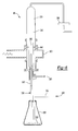
- FIG. 6 is a schematic diagram of an apparatus for making a core material encapsulated by carbon
- FIG. 7 is a schematic illustration of a carbon outer shell on a sacrificial material
- FIG. 8 is a TEM image of an outer carbon shell on a sacrificial material
- FIG. 9 is a schematic illustration of an apparatus for forming a core material encapsulated by carbon.
- FIG. 10 is a TEM image of hollow carbon spheres.
- the present invention discloses a hollow carbon sphere having a carbon shell with an inner free volume.
- a process for making the hollow carbon sphere is disclosed.
- the hollow carbon sphere can be used to encapsulate a material therewithin and/or to support a catalytic material.
- the hollow carbon sphere has utility as a battery material, a catalytic support structure material and the like.
- the process has utility for making hollow carbon spheres.
- the hollow carbon sphere has a total volume that is equal to a volume of the carbon shell plus a volume of the inner free space within the carbon shell.
- the inner free volume is at least 25% of the total volume. In some instances, the inner free volume is at least 50% of the total volume, while in other instances, the inner free volume is at least 75% of the total volume, and in still other instances the inner volume is at least 90% of the total volume.
- a nominal diameter of the hollow carbon sphere can be between 10 and 180 nanometers, and in some instances is between 50 and 150 nanometers. In still other instances, the nominal diameter of the hollow carbon sphere is between 80 and 120 nanometers.
- the carbon shell can have a nominal thickness that is between 2 to 30 nanometers, and in some instances is between 5 and 20 nanometers. In still other instances, the nominal thickness of the carbon shell is between 7 and 10 nanometers.
- the carbon shell can have a pathway therethrough that affords for the passing of material through the shell and into or out of the carbon sphere.
- the pathway can be in the form of porosity and/or a misfit region between two adjacent carbon grains wherein the diffusivity of atoms and/or molecules is enhanced.
- the hollow carbon spheres can be used to encapsulate an electro-active material therein.
- the electro-active material can be a material that alloys with lithium and/or a material that contains lithium.
- the hollow carbon sphere can also serve as a support structure for a catalytic material, the catalytic material being on a surface of the carbon shell.
- the surface can be an outer surface of the carbon shell, or in the alternative an inner surface of the carbon shell.
- the catalytic material can be a material such as platinum, palladium, rhodium, rhenium, iron, nickel, cobalt, silver, gold and/or alloys thereof.
- hollow carbon sphere can be used for drug delivery by having a biologically active material within and/or on the carbon shell.
- the hollow carbon sphere can include a biologically active material or molecule therewithin to be delivered and optionally a polymer that is covalently bound to the biologically active molecule, for example, an antibody or antibody fragment.
- the biologically active molecule can be located within and/or on the outside surface of the hollow carbon sphere.
- the biologically active molecule can be any molecule used to treat a patient, illustratively including a protein, carbohydrate or polysaccharide, nucleic acid, lipid, a combination thereof, or a synthetic molecule, including organic and inorganic materials.
- the hollow carbon spheres can be used as injectable particles, the hollow carbon spheres having a substance to be delivered and a copolymer of poly(alkylene glycol) with poly(lactic-co-glycolic acid), poly(lactic-acid), poly(glycolic acid), or polyanhydride, wherein the poly(alkylene glycol) is covalently bound to an antibody or antibody fragment.
- the hollow carbon spheres can be used to release over long periods of time highly active and effective drugs, such as anticancer drugs, that produce significant side effects when administered systemically. It is appreciated that the controlled release generally decreases the toxic side effects associated with systemic administration of the non-encapsulated drug.
- the polymeric matrix can also provide protection of the drugs against degradation in the plasma for drugs with short biological half-lives.
- a process for making a hollow carbon sphere can include providing a sacrificial material, depositing carbon onto the sacrificial material in order to form a carbon shell and removing the sacrificial material in order to produce the hollow carbon sphere.
- the sacrificial material can be any material that is removable from within the carbon shell by acidic dissolution or alkaline dissolution.
- a precursor in the form of a dry precursor powder, a liquid and/or a vapor of a liquid can be provided, the precursor suspended in an aerosol gas to produce an aerosol containing the precursor.
- the aerosol can be passed through a plasma having a hot zone with at least part of the precursors in the aerosol being vaporized. New particles can be created in the hot zone by reorganization of atoms from the precursor, and sometimes atoms from the aerosol gas as well.
- the aerosol gas can carry the new particles out of the hot zone and into a plasma afterglow region where extremely rapid cooling occurs.
- the particles can then be carried into a zone that is near ambient temperature where the particles can be removed from the aerosol gas generally with a filter. Thereafter, acidic dissolution or alkaline dissolution can be used to remove the core material from within the carbon shell.
- the hot zone of the plasma can be a region of high electromagnetic energy that can be generated using radio frequency, microwave energy or direct current discharge.
- the plasma can be a non-oxidizing plasma and in some instances is a low power atmospheric or near-atmospheric pressure plasma with the plasma generated by focusing microwave energy within a coupler.
- the aerosol gas can be an inert gas, illustratively including helium, argon and combinations thereof.
- the process can further include passing a plasma gas in addition to the aerosol through the hot zone of the plasma, the plasma gas also being an inert gas.
- the core material is a lithium alloying material and can contain an element such as tin, silicon, aluminum, germanium, combinations thereof and the like.
- the embodiment 10 can include one or more hollow carbon spheres 100 , the hollow carbon sphere 100 having a carbon shell 110 and an inner free volume 120 .
- the hollow carbon sphere 100 can include a radius 112 that extends from a center 102 of the sphere to an outer surface 116 of the carbon shell 110 .
- the hollow carbon sphere 100 can have an inner radius 124 that extends from the center 102 of the sphere to an inner surface 118 .
- the hollow carbon sphere 100 can have a total volume equal to 4/3 ⁇ R t 3 wherein R t is equivalent to the radius 112 as shown in FIG. 1 .
- the hollow carbon sphere 100 can have an inner free space volume equal to 4/3 ⁇ R i 3 wherein R i is equal to the inner radius 124 as shown in FIG. 1 .
- the inner free space volume is equal to at least 25% of the total volume for the hollow carbon sphere 100 . In other instances, the inner free space volume is at least 50% of the total volume, while in still other instances, the inner free space volume is at least 75% of the total volume. In still yet other instances, the inner free space volume is at least 90% of the total volume.
- the carbon shell 110 can have a pathway therethrough.
- the pathway can be in the form of porosity 114 as shown in FIG. 1 .
- the porosity 114 can afford for the passing, migration and/or diffusion of atoms and/or molecules through the carbon shell 110 .
- the pathway can be afforded by a misfit region between adjacent carbon grains that are part of the carbon shell 110 .
- FIG. 4 shows a transmission electron microscopy (TEM) image of a hollow carbon sphere with two adjacent grains 111 having different orientations schematically shown at 113 .
- the grains 111 have lines schematically drawn thereon that corresponding to rows of carbon atoms, thereby illustrating that the two grains 111 do not have the same orientation.
- TEM transmission electron microscopy
- the region 113 located between the two adjacent grains 111 can afford for enhanced diffusivity of atoms and/or molecules therethrough.
- atoms and/or molecules from an acid or alkaline solution can pass through the carbon shell and come into contact with the sacrificial material.
- the sacrificial material that has been dissolved can exit the hollow carbon sphere 100 .
- the hollow carbon sphere 100 can have an electro-active material 135 encapsulated therewithin.
- the electro-active material 135 can include a lithium alloying material. It is appreciated that the electro-active material 135 is deposited within the hollow carbon sphere 100 by first passing through the pathway described above of the carbon shell 110 .
- the hollow carbon sphere 100 has a catalytic material 140 supported by the carbon shell 110 .
- the catalytic material 140 can be present on the outer surface 116 and/or the inner surface 118 of the carbon shell 110 . It is appreciated that a biologically active material or molecule can be located within and/or on the carbon shell 110 and thus afford for the hollow carbon sphere to be used for drug delivery.
- the process 20 includes providing a precursor in the form of a powder, a liquid and/or a vapor of a liquid at step 200 and passing the precursor through a plasma torch at step 202 .
- a plasma torch at step 202 .
- at least part of a shell material and at least part of a core material that is contained within the precursor is vaporized.
- the vaporized material then condenses to form a core-shell structured nanoparticle at step 204 .
- the sacrificial material that is within an outer shell is removed and a hollow carbon sphere is produced.
- FIG. 6 provides a schematic representation of an apparatus for producing the core-shell structured nanoparticles at reference numeral 30 .
- an aerosol gas 300 passes through an inlet tube 310 into a precursor container 320 that contains a precursor 322 .
- Flow of the aerosol gas 300 into the precursor container 320 at a sufficient flow rate results in the suspension of the precursor 322 within the aerosol gas 300 to produce an aerosol.
- the precursor 322 can contain core material and shell material.
- the precursor 322 can also contain elements that are not incorporated within the core and/or shell of any core/shell structured nanoparticles that are produced, but may be present to assist in the overall process in some manner.
- the exit tube 330 can pass or flow through the exit tube 330 with at least part of the exit tube 330 passing into a plasma torch 340 .
- the exit tube 330 has a ceramic portion 332 that terminates generally in the middle of a waveguide 360 .
- the waveguide 360 is used to couple microwave energy to the plasma torch 340 .
- a plasma gas 350 which passes within the plasma torch 340 , but exterior to the ceramic portion 332 of the exit tube 330 which has the aerosol passing therethrough.
- a plasma can be generated with a hot zone 342 located within the plasma torch 340 .
- the temperature of the hot zone 342 is such that at least part of the precursor 322 is vaporized.
- the vaporized precursor 322 exits the hot zone 342 of the plasma torch 340 and enters into a chimney region 370 .
- the atoms of the vaporized precursor condense into solid particles.
- the passing or flowing of the aerosol through the hot zone 342 of the plasma torch 340 results in the vaporization of at least part of the core material and at least part of the shell material. Thereafter, the core and shell material atoms condense into core-shell structured nanoparticles.
- the core-shell structured nanoparticles can be collected from a particle filter 390 , from the interior side walls of the chimney region 370 and/or from a particle trap (not shown).
- the core-shell structured nanoparticles After the core-shell structured nanoparticles have been collected, they can be placed within an acidic or alkaline bath.
- the acid or acid or alkaline bath comes into contact with the sacrificial material or inner core and results in dissolution thereof. As such, hollow carbon spheres are produced.
- dry precursor powders were provided by hand grinding a mixture of micrometer tin particles with crystalline anthracene particles to produce the dry precursor powder 322 .
- the weight ratio of tin to anthracene was 50:1, the tin particles had an average diameter of 50 microns and the mixture of tin particles and anthracene crystals was hand ground until the product appeared fully homogeneous.
- the dry precursor powder 322 was placed within the precursor powder container 320 .
- Argon with a flow rate of 200 cubic centimeters per minute (cc/min) at standard temperature and pressure (STP) was used for the plasma gas 350 and was passed through the plasma torch 340 .
- argon with a flow rate of 300 cc/min at STP was used as the aerosol gas 300 and allowed to pass or flow into the precursor powder container 320 .
- the aerosol gas 300 had tin particles and anthracene particles from the dry precursor powder 322 suspended therein, thereby producing an aerosol.
- the aerosol containing the tin and anthracene particles exited the ceramic portion 332 of the exit tube 330 and entered the hot zone of the plasma generally at the middle of the waveguide section 360 .
- the waveguide section 360 coupled microwave energy to the plasma torch 340 such that an absorbed power of approximately 900 watts was present.
- the plasma torch was made from a quartz tube.
- the plasma itself was confined within the quartz torch 340 and the residence time of the plasma gas and the aerosol was relatively short, for example less than 1 second. Thereafter, new particles passed from the hot zone to an afterglow region and finally to a zone that was at near ambient temperature.
- core-shell structured nanoparticles having a tin core and a carbon shell with a mean nanoparticle diameter of 50 nanometers and a relatively tight size distribution were produced.
- FIG. 7 illustrates such a nanoparticle generally at reference numeral 210 , the core-shell structured nanoparticle 210 having an inner core 212 and an outer shell 214 .
- FIG. 8 shows a transmission electron microscopy (TEM) image of actual tin core-carbon shell nanoparticles produced using the parameters disclosed above.
- TEM transmission electron microscopy
- the sacrificial material of the inner core was removed by using a dissolution method as disclosed in U.S. Pat. No. 3,986,970, which is incorporated herein by reference in its entirety.
- precursor powder materials can be used to produce other core-shell structured nanoparticles, for example and for illustrative purposes only, aluminum micron-sized particles and anthracene can be used as precursor materials to produce aluminum-carbon nanoparticles.
- the liquid carbon source 327 was placed in a container 325 with an aerosol gas 300 flowing into the container 325 and above the source 327 before exiting the container 325 .
- vapor of the carbon source is suspended in the aerosol gas 300 as it flowed out of the container 325 and towards the container 320 .
- approximately 900 watts of absorbed power was present at the plasma torch 340 argon was used as the plasma and aerosol gases.
- flow rates of 250 cc/min for the plasma gas 350 , 30 cc/min for the aerosol gas 300 and 160 cc/min for the aerosol gas 300 afforded tin core-carbon shell nanoparticles.
- the sacrificial material was removed as described in the previous example with FIG. 10 showing a TEM image of hollow carbon spheres produced in this manner.
- the present invention is not bound by or to specific flow stream rates, compositions or configurations.
- other gas flow and/or plasma systems are included within the scope of the present invention.
- a method using a direct current (DC) discharge plasma having a one flow gas system wherein an aerosol gas and a plasma gas are one in the same is within the scope of the disclosed inventive method. This method would result in all of the gas that flows through the plasma and the precursor being well mixed before reaching the hot zone, as opposed to the two gas flow system wherein the aerosol gas and the plasma gas mix with each other in the center of the hot zone as described in the examples above.
- DC direct current
Abstract
Description
- 1. Yujie Xiang, Yi Xie, Zhengquan Li, Changzheng Wu and Rang Zhang, Chem, Commun., Royal Society of Chemistry, 2003, 904-905.
- 2. Wu Zhang, Jianwei Liu, Zhen Huang, Dekun Ma, Jianbo Liang, and Yitai Qian, Chemistry Letters, The Chemical Society of Japan, 2004, Vol. 33, No. 10, 1346-1347.
- 3. Fabing Su, X. S. Zhao, Yong Wang, Likui Wang and Jim Yang Lee, J. Mater. Chem., Royal Society of Chemistry, 2006, 16, 4413-4419.
- 4. Zhenhai Wen, Qiang Wang, Qian Zhang, Jinghong Li, Electrochemistry Communications, Elsevier, 2007, 9, 1867-1872.
- 5. Jonathan Phillips, Toshi Shiina, Martin Nemer and Kelvin Lester, Langmuir 22, 2006, 9694.
- 6. Jonathan Phillips, Martin Nemer and John Weigle U.S. Patent Application Publication No. 2006/0198949, USPTO, published Sep. 7, 2006.
Claims (7)
Priority Applications (1)
| Application Number | Priority Date | Filing Date | Title |
|---|---|---|---|
| US13/080,738 US8419998B2 (en) | 2009-02-24 | 2011-04-06 | Process for making hollow carbon spheres |
Applications Claiming Priority (2)
| Application Number | Priority Date | Filing Date | Title |
|---|---|---|---|
| US12/391,794 US20100215960A1 (en) | 2009-02-24 | 2009-02-24 | Hollow carbon spheres |
| US13/080,738 US8419998B2 (en) | 2009-02-24 | 2011-04-06 | Process for making hollow carbon spheres |
Related Parent Applications (1)
| Application Number | Title | Priority Date | Filing Date |
|---|---|---|---|
| US12/391,794 Division US20100215960A1 (en) | 2009-02-24 | 2009-02-24 | Hollow carbon spheres |
Publications (2)
| Publication Number | Publication Date |
|---|---|
| US20110180513A1 US20110180513A1 (en) | 2011-07-28 |
| US8419998B2 true US8419998B2 (en) | 2013-04-16 |
Family
ID=42631232
Family Applications (2)
| Application Number | Title | Priority Date | Filing Date |
|---|---|---|---|
| US12/391,794 Abandoned US20100215960A1 (en) | 2009-02-24 | 2009-02-24 | Hollow carbon spheres |
| US13/080,738 Expired - Fee Related US8419998B2 (en) | 2009-02-24 | 2011-04-06 | Process for making hollow carbon spheres |
Family Applications Before (1)
| Application Number | Title | Priority Date | Filing Date |
|---|---|---|---|
| US12/391,794 Abandoned US20100215960A1 (en) | 2009-02-24 | 2009-02-24 | Hollow carbon spheres |
Country Status (3)
| Country | Link |
|---|---|
| US (2) | US20100215960A1 (en) |
| JP (1) | JP2010222239A (en) |
| CN (1) | CN101905875A (en) |
Families Citing this family (25)
| Publication number | Priority date | Publication date | Assignee | Title |
|---|---|---|---|---|
| KR101910977B1 (en) * | 2011-11-25 | 2018-10-24 | 삼성전자주식회사 | Graphene ball structure and method of manufacturing the same |
| US10370539B2 (en) | 2014-01-30 | 2019-08-06 | Monolith Materials, Inc. | System for high temperature chemical processing |
| US10138378B2 (en) | 2014-01-30 | 2018-11-27 | Monolith Materials, Inc. | Plasma gas throat assembly and method |
| US11939477B2 (en) | 2014-01-30 | 2024-03-26 | Monolith Materials, Inc. | High temperature heat integration method of making carbon black |
| KR102497660B1 (en) | 2014-01-31 | 2023-02-07 | 모놀리스 머티어리얼스 인코포레이티드 | Plasma torch design |
| KR101556470B1 (en) | 2014-03-31 | 2015-10-02 | 연세대학교 산학협력단 | Method for preparing carbon bubble using a process for cracking of heavy hydrocarbon fraction |
| CN104439237A (en) * | 2014-11-20 | 2015-03-25 | 中国科学院长春应用化学研究所 | Preparation method for iron-carbon balls and preparation method for hollow carbon balls |
| EP3253904B1 (en) | 2015-02-03 | 2020-07-01 | Monolith Materials, Inc. | Regenerative cooling method and apparatus |
| WO2017019683A1 (en) | 2015-07-29 | 2017-02-02 | Monolith Materials, Inc. | Dc plasma torch electrical power design method and apparatus |
| JP6567356B2 (en) * | 2015-08-04 | 2019-08-28 | 株式会社クラレ | Hollow carbon particles comprising elemental nitrogen and method for producing hollow carbon particles |
| CN105084341B (en) * | 2015-08-07 | 2017-03-08 | 同济大学 | Non-template method prepares the application of the method for hollow Nano carbon ball and hollow Nano carbon ball |
| JP6974307B2 (en) | 2015-09-14 | 2021-12-01 | モノリス マテリアルズ インコーポレイテッド | Carbon black derived from natural gas |
| CN106887608B (en) * | 2015-12-16 | 2019-04-30 | 中国海洋大学 | The preparation method and application of inexpensive hollow carbon sphere base oxygen reduction catalyst |
| CN109562347A (en) | 2016-04-29 | 2019-04-02 | 巨石材料公司 | Grain processing technique and the addition of the second heat of equipment |
| EP3448936A4 (en) | 2016-04-29 | 2019-12-25 | Monolith Materials, Inc. | Torch stinger method and apparatus |
| US10138129B2 (en) | 2016-05-24 | 2018-11-27 | Ford Global Technologies, Llc | Carbon spheres and methods of making the same |
| CN106139144B (en) * | 2016-06-27 | 2019-02-01 | 华中科技大学同济医学院附属协和医院 | A kind of hyaluronic acid decorated gold-Nano carbon balls and the preparation method and application thereof with synergistic antitumor characteristic |
| CN106517143B (en) * | 2016-11-14 | 2018-08-24 | 扬州大学 | The method that liquid phase excimer laser ablation prepares fluorescence hollow Nano carbon particle |
| WO2018165483A1 (en) | 2017-03-08 | 2018-09-13 | Monolith Materials, Inc. | Systems and methods of making carbon particles with thermal transfer gas |
| CN115637064A (en) | 2017-04-20 | 2023-01-24 | 巨石材料公司 | Particle system and method |
| CA3074220A1 (en) * | 2017-08-28 | 2019-03-07 | Monolith Materials, Inc. | Systems and methods for particle generation |
| CN107572500B (en) * | 2017-10-20 | 2019-12-13 | 中南大学 | Nano/micron carbon hollow sphere and preparation method and application thereof |
| CA3116989A1 (en) | 2017-10-24 | 2019-05-02 | Monolith Materials, Inc. | Particle systems and methods |
| CN111170296B (en) * | 2020-03-30 | 2022-07-15 | 天津大学 | Method for preparing carbon spheres by using low-temperature plasma to carbonize monosaccharides |
| CN111410177B (en) * | 2020-04-23 | 2022-09-23 | 西北工业大学 | Hollow carbon sphere packaged superfine inorganic particle composite material and preparation method and application thereof |
Citations (12)
| Publication number | Priority date | Publication date | Assignee | Title |
|---|---|---|---|---|
| US5593740A (en) * | 1995-01-17 | 1997-01-14 | Synmatix Corporation | Method and apparatus for making carbon-encapsulated ultrafine metal particles |
| US20030026985A1 (en) * | 2001-07-13 | 2003-02-06 | Creavis Gesellschaft F. Techn. U. Innovation Mbh | Tubes having internal diameters in the nanometer range |
| US6841509B1 (en) | 2003-07-21 | 2005-01-11 | Industrial Technology Research Institute | Carbon nanocapsule supported catalysts |
| US20050032635A1 (en) | 2003-08-06 | 2005-02-10 | Yu Jong Sung | HCMS carbon capsule, electrocatalysts for fuel cell supported by HCMS carbon capsule, and method of preparing the same |
| US20050271734A1 (en) | 2001-04-03 | 2005-12-08 | Dennis Donn M | Detoxification and decontamination using nanotechnology therapy |
| WO2006063506A1 (en) | 2004-12-13 | 2006-06-22 | Weijia Yang | Utilization for carbon nanosphere in anti-cancer medicine |
| US20070106363A1 (en) * | 2005-11-04 | 2007-05-10 | Jan Weber | Medical devices having particle-containing regions with diamond-like coatings |
| US20070207081A1 (en) | 2004-03-30 | 2007-09-06 | Hirofumi Takikawa | Carbon Nanoballoon Structure And Method For Preparation Thereof, And Electron Emitter |
| US20080027149A1 (en) | 2004-10-28 | 2008-01-31 | Hiroyuki Aikyou | Spherical Carbon Particles And Their Aggregates |
| US20080087314A1 (en) | 2006-10-13 | 2008-04-17 | Tulane University | Homogeneous thermoelectric nanocomposite using core-shell nanoparticles |
| EP1959508A1 (en) | 2005-12-07 | 2008-08-20 | Toyota Jidosha Kabushiki Kaisha | Thermoelectric conversion material and process for producing the same |
| US20090082474A1 (en) | 2007-09-24 | 2009-03-26 | Headwaters Technology Innovation, Llc | Highly dispersible carbon nanospheres in a polar solvent and methods for making same |
Family Cites Families (6)
| Publication number | Priority date | Publication date | Assignee | Title |
|---|---|---|---|---|
| JP3598291B2 (en) * | 2002-01-08 | 2004-12-08 | 独立行政法人 科学技術振興機構 | Nanographite spherical body and method for producing the same |
| KR100905847B1 (en) * | 2003-01-17 | 2009-07-02 | 주식회사 엘지생활건강 | Impregnated multilayered mesoporous and microporus core-shell carbon nanoball for deodorising |
| DE112004001663T5 (en) * | 2003-09-10 | 2006-07-27 | Nahum Paransky | Generation of nanoparticles and microparticles |
| KR100730119B1 (en) * | 2004-11-02 | 2007-06-19 | 삼성에스디아이 주식회사 | Carbon nanosphere having one or more open portion, method for preparing the same, carbon nanosphere impregnated catalyst using the carbon nanosphere and fuel cell adopting the catalyst |
| JP2007031268A (en) * | 2005-06-21 | 2007-02-08 | Mitsubishi Chemicals Corp | Surface modified carbon particle and its manufacturing method |
| US8057900B2 (en) * | 2008-06-20 | 2011-11-15 | Toyota Motor Engineering & Manufacturing North America, Inc. | Material with core-shell structure |
-
2009
- 2009-02-24 US US12/391,794 patent/US20100215960A1/en not_active Abandoned
-
2010
- 2010-02-24 CN CN2010101809833A patent/CN101905875A/en active Pending
- 2010-02-24 JP JP2010038831A patent/JP2010222239A/en active Pending
-
2011
- 2011-04-06 US US13/080,738 patent/US8419998B2/en not_active Expired - Fee Related
Patent Citations (12)
| Publication number | Priority date | Publication date | Assignee | Title |
|---|---|---|---|---|
| US5593740A (en) * | 1995-01-17 | 1997-01-14 | Synmatix Corporation | Method and apparatus for making carbon-encapsulated ultrafine metal particles |
| US20050271734A1 (en) | 2001-04-03 | 2005-12-08 | Dennis Donn M | Detoxification and decontamination using nanotechnology therapy |
| US20030026985A1 (en) * | 2001-07-13 | 2003-02-06 | Creavis Gesellschaft F. Techn. U. Innovation Mbh | Tubes having internal diameters in the nanometer range |
| US6841509B1 (en) | 2003-07-21 | 2005-01-11 | Industrial Technology Research Institute | Carbon nanocapsule supported catalysts |
| US20050032635A1 (en) | 2003-08-06 | 2005-02-10 | Yu Jong Sung | HCMS carbon capsule, electrocatalysts for fuel cell supported by HCMS carbon capsule, and method of preparing the same |
| US20070207081A1 (en) | 2004-03-30 | 2007-09-06 | Hirofumi Takikawa | Carbon Nanoballoon Structure And Method For Preparation Thereof, And Electron Emitter |
| US20080027149A1 (en) | 2004-10-28 | 2008-01-31 | Hiroyuki Aikyou | Spherical Carbon Particles And Their Aggregates |
| WO2006063506A1 (en) | 2004-12-13 | 2006-06-22 | Weijia Yang | Utilization for carbon nanosphere in anti-cancer medicine |
| US20070106363A1 (en) * | 2005-11-04 | 2007-05-10 | Jan Weber | Medical devices having particle-containing regions with diamond-like coatings |
| EP1959508A1 (en) | 2005-12-07 | 2008-08-20 | Toyota Jidosha Kabushiki Kaisha | Thermoelectric conversion material and process for producing the same |
| US20080087314A1 (en) | 2006-10-13 | 2008-04-17 | Tulane University | Homogeneous thermoelectric nanocomposite using core-shell nanoparticles |
| US20090082474A1 (en) | 2007-09-24 | 2009-03-26 | Headwaters Technology Innovation, Llc | Highly dispersible carbon nanospheres in a polar solvent and methods for making same |
Non-Patent Citations (10)
| Title |
|---|
| Chun-Yi Chang-Chien et al; Synthesis of Carbon and Silica Hollow Spheres with Mesoporous Shells using Polyethylene Oxide/Phenol Formaldehyde Polymer Blend; Eur. J. Inorg. Chem. 2007; pp. 3798-3804. |
| Crystalline Carbon Hollow Spheres, Crystalline Carbon-SnO2 Hollow Spheres and Crystalline SnO2 Hollow Spheres: Synthesis and Performance in Reversible Li-Ion Storage, Wang Yong et al. Feb. 10, 2006. * |
| Fabing Su; Hollow Carbon Spheres With a Controllable Shell Structure; Journals of Materials Chemistry 2006; pp. 4413-4419. |
| Feng Li et al; CoO-loaded Graphitable Carbon Hollow Spheres as Anode Materials for Lithium-ion Battery; Journal of Power Sources 177 (2008) pp. 546-552. |
| Purkayastha Arup et al., Advanced materials, 2006, vol. 18, pp. 2958-2963. |
| Shujian Ding et al; Porous Carbon and Carbon Composite Hollow Spheres; Colloid Polym Sci (2008). |
| Wu Zhang; Large Scale Synthesis of Carbon Hollow Spheres From Metal Zinc Powder and Ethanol; Chemistry Letters vol. 33., No. 10 (2004). |
| Yujie Xiong et al.; A Novel Approach to Carbon Hollow Spheres and Vessels From CCI4 At Low Temperatures; Chem.Commun., 2003; pp. 904-905. |
| Zhenhai Wen et al; Hollow Carbon Spheres with Wide Size Distribution as Anode Catalyst Support for Direct Methanol Fuel Cells; ScienceDirect; Electrochemistry Communications 9; (2007) 1867-1872. |
| Zhen-Xue Liu et al.; Nano-sized Carbon Hollow Spheres for Abatement of Ethylene; Topics in Catalysis; vol. 39. Nos. 3-4; Oct. 2006; pp. 221-226. |
Also Published As
| Publication number | Publication date |
|---|---|
| CN101905875A (en) | 2010-12-08 |
| JP2010222239A (en) | 2010-10-07 |
| US20100215960A1 (en) | 2010-08-26 |
| US20110180513A1 (en) | 2011-07-28 |
Similar Documents
| Publication | Publication Date | Title |
|---|---|---|
| US8419998B2 (en) | Process for making hollow carbon spheres | |
| CA3024473C (en) | Metal powder atomization manufacturing processes | |
| CA3020720C (en) | Reactive metal powders in-flight heat treatment processes | |
| US6465052B1 (en) | Method for production of nano-porous coatings | |
| US20110006254A1 (en) | Process to make electrochemically active/inactive nanocomposite material | |
| JP5823393B2 (en) | Incorporation of nanoparticles into composite fibers | |
| JP5847996B2 (en) | Method for producing composite particles | |
| EP2370355B1 (en) | Method for the synthesis of carbon nanotubes on long particulate micrometric materials | |
| JP2013536327A (en) | Method for electrospinning fibers | |
| US20140249021A1 (en) | Wet chemical and plasma methods of forming stable ptpd catalysts | |
| JP2010001563A (en) | Process to make core-shell structured nanoparticle | |
| JP2013500937A5 (en) | ||
| JP5412848B2 (en) | Manufacturing method of microstructure material | |
| TW201014937A (en) | Method for producing semiconductor particles | |
| KR20160021127A (en) | Method and apparatus for preparing coated particles | |
| US20030108683A1 (en) | Manufacturing method for nano-porous coatings and thin films | |
| JP2014224337A (en) | Liquid electrospray method and liquid electrospray apparatus | |
| JP2004149954A (en) | Metal/metal compound coated carbon nanofiber and method for producing the same | |
| US7504083B2 (en) | Process of forming a sol-gel/metal hydride composite | |
| Li et al. | Fabrication and applications of multi-fluidic electrospinning multi-structure hollow and core–shell nanofibers | |
| CN111687425B (en) | Core-shell structure nano material and preparation method thereof | |
| US9994445B2 (en) | Spherical nanoparticle hydrides, and methods for making the same | |
| JP2015213905A (en) | Liquid electrospray method and liquid electrospray apparatus | |
| JPH1043502A (en) | Production of super-finely crystallized product | |
| KR20110097431A (en) | Method for synthesis and morphological control of carbon nanotubes |
Legal Events
| Date | Code | Title | Description |
|---|---|---|---|
| AS | Assignment |
Owner name: LOS ALAMOS NATIONAL LAB, NEW MEXICO Free format text: ASSIGNMENT OF ASSIGNORS INTEREST;ASSIGNOR:PHILLIPS, JONATHAN;REEL/FRAME:026080/0943 Effective date: 20090223 Owner name: REGENTS OF THE UNIVERSITY OF NEW MEXICO, NEW MEXIC Free format text: ASSIGNMENT OF ASSIGNORS INTEREST;ASSIGNOR:LUHRS, CLAUDIA C.;REEL/FRAME:026081/0870 Effective date: 20090211 Owner name: TOYOTA MOTOR ENGINEERING & MANUFACTURING NORTH AME Free format text: ASSIGNMENT OF ASSIGNORS INTEREST;ASSIGNORS:RICHARD, MONIQUE N.;KNAPP, ANGELA MICHELLE;REEL/FRAME:026080/0821 Effective date: 20090210 |
|
| REMI | Maintenance fee reminder mailed | ||
| LAPS | Lapse for failure to pay maintenance fees | ||
| STCH | Information on status: patent discontinuation |
Free format text: PATENT EXPIRED DUE TO NONPAYMENT OF MAINTENANCE FEES UNDER 37 CFR 1.362 |
|
| FP | Lapsed due to failure to pay maintenance fee |
Effective date: 20170416 |