US8480602B1 - Rehabilitation apparatus for correcting ambulation - Google Patents
Rehabilitation apparatus for correcting ambulation Download PDFInfo
- Publication number
- US8480602B1 US8480602B1 US12/932,277 US93227711A US8480602B1 US 8480602 B1 US8480602 B1 US 8480602B1 US 93227711 A US93227711 A US 93227711A US 8480602 B1 US8480602 B1 US 8480602B1
- Authority
- US
- United States
- Prior art keywords
- strap
- straps
- patient
- resistance
- end secured
- Prior art date
- Legal status (The legal status is an assumption and is not a legal conclusion. Google has not performed a legal analysis and makes no representation as to the accuracy of the status listed.)
- Expired - Fee Related, expires
Links
Images


Classifications
-
- A—HUMAN NECESSITIES
- A61—MEDICAL OR VETERINARY SCIENCE; HYGIENE
- A61H—PHYSICAL THERAPY APPARATUS, e.g. DEVICES FOR LOCATING OR STIMULATING REFLEX POINTS IN THE BODY; ARTIFICIAL RESPIRATION; MASSAGE; BATHING DEVICES FOR SPECIAL THERAPEUTIC OR HYGIENIC PURPOSES OR SPECIFIC PARTS OF THE BODY
- A61H1/00—Apparatus for passive exercising; Vibrating apparatus ; Chiropractic devices, e.g. body impacting devices, external devices for briefly extending or aligning unbroken bones
- A61H1/02—Stretching or bending or torsioning apparatus for exercising
- A61H1/0237—Stretching or bending or torsioning apparatus for exercising for the lower limbs
- A61H1/0244—Hip
-
- A—HUMAN NECESSITIES
- A61—MEDICAL OR VETERINARY SCIENCE; HYGIENE
- A61H—PHYSICAL THERAPY APPARATUS, e.g. DEVICES FOR LOCATING OR STIMULATING REFLEX POINTS IN THE BODY; ARTIFICIAL RESPIRATION; MASSAGE; BATHING DEVICES FOR SPECIAL THERAPEUTIC OR HYGIENIC PURPOSES OR SPECIFIC PARTS OF THE BODY
- A61H3/00—Appliances for aiding patients or disabled persons to walk about
- A61H3/008—Using suspension devices for supporting the body in an upright walking or standing position, e.g. harnesses
-
- A—HUMAN NECESSITIES
- A63—SPORTS; GAMES; AMUSEMENTS
- A63B—APPARATUS FOR PHYSICAL TRAINING, GYMNASTICS, SWIMMING, CLIMBING, OR FENCING; BALL GAMES; TRAINING EQUIPMENT
- A63B21/00—Exercising apparatus for developing or strengthening the muscles or joints of the body by working against a counterforce, with or without measuring devices
- A63B21/00181—Exercising apparatus for developing or strengthening the muscles or joints of the body by working against a counterforce, with or without measuring devices comprising additional means assisting the user to overcome part of the resisting force, i.e. assisted-active exercising
-
- A—HUMAN NECESSITIES
- A63—SPORTS; GAMES; AMUSEMENTS
- A63B—APPARATUS FOR PHYSICAL TRAINING, GYMNASTICS, SWIMMING, CLIMBING, OR FENCING; BALL GAMES; TRAINING EQUIPMENT
- A63B22/00—Exercising apparatus specially adapted for conditioning the cardio-vascular system, for training agility or co-ordination of movements
- A63B22/02—Exercising apparatus specially adapted for conditioning the cardio-vascular system, for training agility or co-ordination of movements with movable endless bands, e.g. treadmills
- A63B22/0235—Exercising apparatus specially adapted for conditioning the cardio-vascular system, for training agility or co-ordination of movements with movable endless bands, e.g. treadmills driven by a motor
-
- A—HUMAN NECESSITIES
- A63—SPORTS; GAMES; AMUSEMENTS
- A63B—APPARATUS FOR PHYSICAL TRAINING, GYMNASTICS, SWIMMING, CLIMBING, OR FENCING; BALL GAMES; TRAINING EQUIPMENT
- A63B69/00—Training appliances or apparatus for special sports
- A63B69/0064—Attachments on the trainee preventing falling
-
- A—HUMAN NECESSITIES
- A61—MEDICAL OR VETERINARY SCIENCE; HYGIENE
- A61H—PHYSICAL THERAPY APPARATUS, e.g. DEVICES FOR LOCATING OR STIMULATING REFLEX POINTS IN THE BODY; ARTIFICIAL RESPIRATION; MASSAGE; BATHING DEVICES FOR SPECIAL THERAPEUTIC OR HYGIENIC PURPOSES OR SPECIFIC PARTS OF THE BODY
- A61H2201/00—Characteristics of apparatus not provided for in the preceding codes
- A61H2201/12—Driving means
- A61H2201/1253—Driving means driven by a human being, e.g. hand driven
- A61H2201/1261—Driving means driven by a human being, e.g. hand driven combined with active exercising of the patient
- A61H2201/1284—Driving means driven by a human being, e.g. hand driven combined with active exercising of the patient using own weight
-
- A—HUMAN NECESSITIES
- A61—MEDICAL OR VETERINARY SCIENCE; HYGIENE
- A61H—PHYSICAL THERAPY APPARATUS, e.g. DEVICES FOR LOCATING OR STIMULATING REFLEX POINTS IN THE BODY; ARTIFICIAL RESPIRATION; MASSAGE; BATHING DEVICES FOR SPECIAL THERAPEUTIC OR HYGIENIC PURPOSES OR SPECIFIC PARTS OF THE BODY
- A61H2201/00—Characteristics of apparatus not provided for in the preceding codes
- A61H2201/16—Physical interface with patient
- A61H2201/1602—Physical interface with patient kind of interface, e.g. head rest, knee support or lumbar support
- A61H2201/165—Wearable interfaces
- A61H2201/1652—Harness
Definitions
- the present invention relates to rehabilitation apparatus used in conjunction with unweighting apparatus for correcting ambulatory problems.
- rehabilitation apparatus which includes structure anchored to the user for converting the vertical resistance force provided by the unweighting apparatus to a resistance force having a horizontal component for acting on the hip flexors and extensors of a patient when walking.
- a human body rehabilitation apparatus for use with unweighting apparatus having an overhead spreader bar having a vest for fitting around a waist of a patient and a left side shoulder strap and a right side shoulder strap each attached to the vest and each having a distal end connected to the overhead spreader bar.
- a left side thigh cuff and a right side thigh cuff for fitting around the thighs of a patient and having an adjustable length first resistance strap connected between the left side thigh cuff and the overhead spreader bar and a second adjustable length resistance strap having one end secured to the right side thigh cuff and a distal end connected to the overhead spreader bar.
- a left side foot strap and a right side foot strap are provided for fitting around the forward end of the left and right foot, respectively, of a patient.
- An adjustable length first gait strap has one end secured to the left side foot strap and a distal end connected to the spreader bar and an adjustable length second gait strap having one end secured to the right side foot strap and a distal end secured to the spreader bar.
- An elongate roll having a preselected thickness is suspended from the vest and positioned to extend laterally across the patient below the vest adjacent the pelvis area of the patient.
- the elongate roll having a series of spaced apart loops extending across the face of the elongate roll for selectively receiving the first and second resistance straps and the first and second gait straps.
- the elongate roll is used to convert an essentially vertical upward forces provided by the unweighting apparatus through the first and second resistance straps and the first and second gait straps to forces having a horizontal component.
- FIG. 1 is a perspective plan view of the rehabilitation apparatus according to the present invention.
- FIG. 2 is a perspective view of the rehabilitation apparatus shown in FIG. 1 fitted on a patient;
- FIG. 3 is a partial plan view of the rehabilitation apparatus shown in FIG. 1 fitted on one leg of a patient;
- FIG. 4 is a plan view of a cylindrical body used with the present invention.
- FIG. 5 is a detail view showing the attachment of the cylindrical body shown in FIG. 4 to a vest worn by a patient;
- FIG. 6 is a plan view of a thigh cuff used with the present invention.
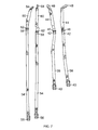
- FIG. 7 is a plan view of resistance straps used with the present invention.
- FIG. 8 is a perspective view of the attachment of shoulder straps of a vest and resistance straps to a suspension chain connected to unweighting apparatus (not shown);
- FIG. 9 is a perspective view of a foot strap used with the present invention fitted on a foot of a patient.
- FIG. 1 Rehabilitation apparatus 10 for correcting ambulation is shown in FIG. 1 and described in Exhibit A attached hereto and incorporated herein by reference.
- the rehabilitation apparatus 10 shown in FIG. 1 , is used in conjunction with unweighting apparatus 12 as shown in FIG. 2 .
- a spreader bar 14 is suspended from the unweighting apparatus 12 .
- a pair of suspension chains 16 are attached to the spreader bar 14 and are adapted for connecting to the shoulder straps 17 of a vest 18 as shown in FIG. 1 .
- the rehabilitation device 10 as shown in FIG. 3 is configured with one leg of a patient. A similar configuration is used for the other leg of the patient but is not shown in this figure for clarity.
- the rehabilitation device includes an elongate roll 20 preferably constructed of a semi-rigid material.
- the elongate roll 20 is shown in FIG. 4 .
- the elongate roll 20 includes a pair of length adjustment buckles 22 attached to the elongate roll 20 as shown in FIGS. 4 and 5 .
- a strap 24 is threaded through each of the length adjustment buckles 22 as shown in FIG. 5 and a male buckle 26 is secured to the strap 24 at one end thereof.
- the male buckle 26 is connected to a female buckle 28 attached to the vest 18 .
- a strap 30 is sewn to elongate roll 20 at spaced apart locations forming loops 32 as shown in FIG. 5 on both the anterior and posterior sides of elongate roll 20 .
- a thigh cuff 34 as shown in FIG. 6 is secured to a leg of a patient as shown in FIG. 3 .
- a thigh cuff 34 for each leg of the patient. The ends of the cuff are secured together with a hook and loop connection (not shown).
- a female buckle 36 is secured to the thigh cuff 34 as shown in FIG. 6 .
- a resistance strap 38 as shown in FIG. 7 , has a male buckle 40 located at one end thereof. The male buckle 40 is used to secure the resistance strap 38 to the female buckle 36 of the thigh cuff 34 . At the opposite end of the resistance strap 38 is secured a strap length adjusting female buckle 42 .
- a strap 44 has a male buckle 46 secured at one end thereof for buckling with the female buckle 42 as shown in FIG. 7 .
- a clip 48 At the opposite end of the strap 44 is secured a clip 48 for securing the strap 44 to the suspension chain 16 as shown in FIG. 8 .
- a foot strap 50 is adapted for fitting around the forward end of a foot of a patient. There is provided a foot strap 50 for each foot of the patient. The foot strap 50 is provided with a female buckle 52 .
- a gait strap 54 as shown in FIG. 7 , has a male buckle 56 located at one end thereof for buckling with the female buckle 52 of the foot strap 50 as shown in FIG. 9 .
- a strap length female buckle 58 At the opposite end of the gait strap 54 is provided a strap length female buckle 58 .
- a strap 60 has a male buckle 62 secured at one end thereof for buckling with the female buckle 58 as shown in FIG. 7 .
- a clip 64 for attachment with a suspension chain 56 as shown in FIG. 8 .
- the elongate roll 20 is used to convert the essentially vertical vector of the resistance force acting through resistance straps 38 and gait straps 54 on the thigh and foot respectively of a patient to a vector having a horizontal component.
- the rehabilitation device 10 may be used in different configurations to correct various ambulatory problems.
- a first set up the elongate roll 20 is suspended from the vest 18 with straps 24 and buckles 28 in an anterior position as shown in FIG. 2 and FIG. 5 .
- Thigh cuffs 34 are secured to the legs of a patient with the buckles 36 positioned on the anterior side of the thigh.
- the resistance straps 38 are threaded through loops 32 provided on the anterior side of elongate roll 20 .
- the resistance straps 38 are then connected to chain 16 as shown in FIGS. 7 and 8 through length adjustment buckles 42 and 46 .
- the length of resistance straps 38 are adjusted to adjust the unweighting tension on each leg.
- the resistance straps 38 assist the hip flexors and provide resistance to the extensors.
- resistance straps 38 are threaded through outer loops 32 .
- the straps 38 are threaded through inner loops 32 .
- the elongate roll 20 is suspended from the vest 18 in a posterior position with straps 24 working in cooperation with buckles 28 provided on the posterior side of the vest 18 .
- Thigh cuffs 34 are secured to the legs of a patient with the buckles 36 positioned on the posterior side of the thighs.
- the resistance straps 38 are threaded through loops 32 provided on the posterior side of the elongate roll 20 .
- the resistance straps are then connected to chain 16 as with the first example.
- the length of resistance straps are adjusted to adjust the unweighting tension on each leg.
- the resistance straps 38 assist the extensors and provide resistance to the hip flexors.
- resistance straps 38 are threaded through outer loops 32 .
- the straps 38 are threaded through inner loops 32 .
- the elongate roll 20 is suspended from the vest 18 in an anterior position with straps 24 and buckles 38 .
- Thigh cuffs are secured to the legs of a patient with the buckles 36 positioned on the anterior side of the thigh.
- the resistance straps 38 are threaded through loops 32 provided on the anterior side of elongate roll 20 .
- the resistance straps are then connected to chain 16 and the length adjusted to adjust the unweighting tension on each leg.
- the foot straps 50 are then fitted around the forward end of the feet as shown in FIG. 9 .
- the gait straps 54 are then threaded through the middle loops 32 provided on the anterior side of elongate roll 20 and then connected to chain 16 as before through length adjustment buckles 58 and 62 .
- the length of gait straps 54 are adjusted to adjust the unweighting tension on each foot. With this arrangement the walking pattern of a patient is modified to have a controlled heel strike.
Abstract
Rehabilitation apparatus for use with unweighting apparatus including a vest having shoulder straps connected to the unweighting apparatus. Also included are a pair of thigh cuffs having resistance straps connected to the unweighting apparatus and a pair of foot straps having gait straps connected to the unweighting apparatus. An elongate roll is suspended from the vest and extends across the patient adjacent the pelvis area of the patient. The resistance straps and gait straps are threaded through loops provided on the front fact of the elongate roll.
Description
This application claims the benefit of provisional application Ser. No. 61/338,632 filed on Feb. 22, 2010.
The present invention relates to rehabilitation apparatus used in conjunction with unweighting apparatus for correcting ambulatory problems. A need exists for rehabilitation apparatus which includes structure anchored to the user for converting the vertical resistance force provided by the unweighting apparatus to a resistance force having a horizontal component for acting on the hip flexors and extensors of a patient when walking.
A human body rehabilitation apparatus for use with unweighting apparatus having an overhead spreader bar having a vest for fitting around a waist of a patient and a left side shoulder strap and a right side shoulder strap each attached to the vest and each having a distal end connected to the overhead spreader bar. A left side thigh cuff and a right side thigh cuff for fitting around the thighs of a patient and having an adjustable length first resistance strap connected between the left side thigh cuff and the overhead spreader bar and a second adjustable length resistance strap having one end secured to the right side thigh cuff and a distal end connected to the overhead spreader bar. A left side foot strap and a right side foot strap are provided for fitting around the forward end of the left and right foot, respectively, of a patient. An adjustable length first gait strap has one end secured to the left side foot strap and a distal end connected to the spreader bar and an adjustable length second gait strap having one end secured to the right side foot strap and a distal end secured to the spreader bar. An elongate roll having a preselected thickness is suspended from the vest and positioned to extend laterally across the patient below the vest adjacent the pelvis area of the patient. The elongate roll having a series of spaced apart loops extending across the face of the elongate roll for selectively receiving the first and second resistance straps and the first and second gait straps. The elongate roll is used to convert an essentially vertical upward forces provided by the unweighting apparatus through the first and second resistance straps and the first and second gait straps to forces having a horizontal component.
In order that the invention may be clearly understood and readily carried into effect, a preferred embodiment of the invention will now be described, by way of example only, with reference to the accompanying drawings wherein:
The rehabilitation apparatus 10, shown in FIG. 1 , is used in conjunction with unweighting apparatus 12 as shown in FIG. 2 . A spreader bar 14 is suspended from the unweighting apparatus 12. A pair of suspension chains 16 are attached to the spreader bar 14 and are adapted for connecting to the shoulder straps 17 of a vest 18 as shown in FIG. 1 . The rehabilitation device 10 as shown in FIG. 3 is configured with one leg of a patient. A similar configuration is used for the other leg of the patient but is not shown in this figure for clarity.
The rehabilitation device includes an elongate roll 20 preferably constructed of a semi-rigid material. The elongate roll 20 is shown in FIG. 4 . The elongate roll 20 includes a pair of length adjustment buckles 22 attached to the elongate roll 20 as shown in FIGS. 4 and 5 . A strap 24 is threaded through each of the length adjustment buckles 22 as shown in FIG. 5 and a male buckle 26 is secured to the strap 24 at one end thereof. The male buckle 26 is connected to a female buckle 28 attached to the vest 18. As shown in FIG. 5 , there are buckles 28 attached to the vest on the anterior and posterior sides of vest 18.
A strap 30 is sewn to elongate roll 20 at spaced apart locations forming loops 32 as shown in FIG. 5 on both the anterior and posterior sides of elongate roll 20.
A thigh cuff 34 as shown in FIG. 6 is secured to a leg of a patient as shown in FIG. 3 . There is provided a thigh cuff 34 for each leg of the patient. The ends of the cuff are secured together with a hook and loop connection (not shown). A female buckle 36 is secured to the thigh cuff 34 as shown in FIG. 6 . A resistance strap 38, as shown in FIG. 7 , has a male buckle 40 located at one end thereof. The male buckle 40 is used to secure the resistance strap 38 to the female buckle 36 of the thigh cuff 34. At the opposite end of the resistance strap 38 is secured a strap length adjusting female buckle 42. A strap 44 has a male buckle 46 secured at one end thereof for buckling with the female buckle 42 as shown in FIG. 7 . At the opposite end of the strap 44 is secured a clip 48 for securing the strap 44 to the suspension chain 16 as shown in FIG. 8 .
A foot strap 50, as shown in FIG. 9 , is adapted for fitting around the forward end of a foot of a patient. There is provided a foot strap 50 for each foot of the patient. The foot strap 50 is provided with a female buckle 52. A gait strap 54, as shown in FIG. 7 , has a male buckle 56 located at one end thereof for buckling with the female buckle 52 of the foot strap 50 as shown in FIG. 9 . At the opposite end of the gait strap 54 is provided a strap length female buckle 58. A strap 60 has a male buckle 62 secured at one end thereof for buckling with the female buckle 58 as shown in FIG. 7 . At the opposite end of strap 60 is provided a clip 64 for attachment with a suspension chain 56 as shown in FIG. 8 .
The elongate roll 20, as used with the present invention, is used to convert the essentially vertical vector of the resistance force acting through resistance straps 38 and gait straps 54 on the thigh and foot respectively of a patient to a vector having a horizontal component.
The rehabilitation device 10 may be used in different configurations to correct various ambulatory problems. For example, in a first set up the elongate roll 20 is suspended from the vest 18 with straps 24 and buckles 28 in an anterior position as shown in FIG. 2 and FIG. 5 . Thigh cuffs 34 are secured to the legs of a patient with the buckles 36 positioned on the anterior side of the thigh. The resistance straps 38 are threaded through loops 32 provided on the anterior side of elongate roll 20. The resistance straps 38 are then connected to chain 16 as shown in FIGS. 7 and 8 through length adjustment buckles 42 and 46. The length of resistance straps 38 are adjusted to adjust the unweighting tension on each leg. When a patient walks on a tread mill as shown in FIG. 2 the resistance straps 38 assist the hip flexors and provide resistance to the extensors. For a wider gait, resistance straps 38 are threaded through outer loops 32. For a narrower gait, the straps 38 are threaded through inner loops 32.
As another example, the elongate roll 20 is suspended from the vest 18 in a posterior position with straps 24 working in cooperation with buckles 28 provided on the posterior side of the vest 18. Thigh cuffs 34 are secured to the legs of a patient with the buckles 36 positioned on the posterior side of the thighs. The resistance straps 38 are threaded through loops 32 provided on the posterior side of the elongate roll 20. The resistance straps are then connected to chain 16 as with the first example. The length of resistance straps are adjusted to adjust the unweighting tension on each leg. With this arrangement, when a patient walks on a tread mill the resistance straps 38 assist the extensors and provide resistance to the hip flexors. Again, for a wider gait, resistance straps 38 are threaded through outer loops 32. For a narrower gait the straps 38 are threaded through inner loops 32.
As a further example, and as shown in FIG. 2 , the elongate roll 20 is suspended from the vest 18 in an anterior position with straps 24 and buckles 38. Thigh cuffs are secured to the legs of a patient with the buckles 36 positioned on the anterior side of the thigh. The resistance straps 38 are threaded through loops 32 provided on the anterior side of elongate roll 20. The resistance straps are then connected to chain 16 and the length adjusted to adjust the unweighting tension on each leg. The foot straps 50 are then fitted around the forward end of the feet as shown in FIG. 9 . The gait straps 54 are then threaded through the middle loops 32 provided on the anterior side of elongate roll 20 and then connected to chain 16 as before through length adjustment buckles 58 and 62. The length of gait straps 54 are adjusted to adjust the unweighting tension on each foot. With this arrangement the walking pattern of a patient is modified to have a controlled heel strike.
While the fundamental novel features of the invention have been shown and described, it should be understood that various substitutions, modifications, and variations may be made by those skilled in the arts, without departing from the spirit or scope of the invention. Accordingly, all such modifications or variations are included in the scope of the invention as defined by the following
Claims (2)
1. A human body rehabilitation apparatus for use with an unweighting apparatus having an overhead spreader bar comprising
a vest for securely fitting around a waist of a patient;
a left side shoulder strap and a right side shoulder strap, each attached to the vest and each having a portion connected to a separate suspension chain attached to the overhead spreader bar;
a left side thigh cuff and a right side thigh cuff;
an adjustable length first resistance strap having one end secured to the left side thigh cuff and a distal end secured to the corresponding suspension chain;
a second resistance strap having one end secured to the right side thigh cuff and a distal end secured to the corresponding suspension chain; and
an elongate roll having a preselected thickness, the elongate roll suspended from the vest and positioned to extend laterally across the patient below the vest adjacent a pelvis area of the patient;
the elongate roll having a series of spaced apart loops extending across a front face of the elongate roll for selectively receiving the first and second resistance straps;
whereby the elongate roll converts an essentially vertically upward force provided by the unweighting apparatus through the first and second resistance straps to a force which has a horizontal component.
2. The human body rehabilitation apparatus according to claim 1 further including:
a left side foot strap for fitting around a forward end of a left foot of a patient and a right side foot strap for fitting around a forward end of a right foot of a patient;
a first gait strap having one end secured to the left side foot strap and a distal end secured to the corresponding suspension chain;
a second gait strap having one end secured to the right side foot strap and a distal end secured to the corresponding suspension chain;
the first and second gait straps threaded through selected loops provided in the elongate roll;
whereby the elongate roll connects an essentially vertically upward force provided by the unweighting apparatus through the first and second gait straps to a force having a horizontal component.
Priority Applications (1)
| Application Number | Priority Date | Filing Date | Title |
|---|---|---|---|
| US12/932,277 US8480602B1 (en) | 2010-02-22 | 2011-02-22 | Rehabilitation apparatus for correcting ambulation |
Applications Claiming Priority (2)
| Application Number | Priority Date | Filing Date | Title |
|---|---|---|---|
| US33863210P | 2010-02-22 | 2010-02-22 | |
| US12/932,277 US8480602B1 (en) | 2010-02-22 | 2011-02-22 | Rehabilitation apparatus for correcting ambulation |
Publications (1)
| Publication Number | Publication Date |
|---|---|
| US8480602B1 true US8480602B1 (en) | 2013-07-09 |
Family
ID=48701355
Family Applications (1)
| Application Number | Title | Priority Date | Filing Date |
|---|---|---|---|
| US12/932,277 Expired - Fee Related US8480602B1 (en) | 2010-02-22 | 2011-02-22 | Rehabilitation apparatus for correcting ambulation |
Country Status (1)
| Country | Link |
|---|---|
| US (1) | US8480602B1 (en) |
Cited By (24)
| Publication number | Priority date | Publication date | Assignee | Title |
|---|---|---|---|---|
| US20130117908A1 (en) * | 2011-11-10 | 2013-05-16 | Donald J. Dyson | Lift pants for a patient lift system |
| US20140138995A1 (en) * | 2011-07-07 | 2014-05-22 | Roger Kenneth Leib | Chair, Frame and Lifting Garment Useful for Patients |
| CN104800039A (en) * | 2014-01-29 | 2015-07-29 | 余木村 | Spinal rehabilitation device |
| US20160001119A1 (en) * | 2013-03-14 | 2016-01-07 | Alterg, Inc. | Cantilevered unweighting systems |
| US20160008650A1 (en) * | 2013-03-14 | 2016-01-14 | Alterg, Inc. | Support frame and related unweighting system |
| US9370680B1 (en) * | 2011-07-11 | 2016-06-21 | Lightspeed Running & Rehabilitation Systems, LLC | Body weight support system for therapeutic and physical training, and method of use thereof |
| CN105832496A (en) * | 2016-03-17 | 2016-08-10 | 合肥工业大学 | Novel lower extremity exoskeleton rehabilitation training device and training method |
| US9498696B1 (en) * | 2014-09-07 | 2016-11-22 | Eli Razon | Body support system for gait training exercise on a treadmill |
| JP2016198273A (en) * | 2015-04-09 | 2016-12-01 | 株式会社福原鋳物製作所 | Function reinforcement method of walking support outfit and walking support outfit |
| US20170056277A1 (en) * | 2015-08-26 | 2017-03-02 | James Leckey Design Limited | Support harness |
| US20170296415A1 (en) * | 2016-03-24 | 2017-10-19 | Gerry Cook | Exercise vest to allow one person to easily lift patient out of wheelchair |
| US9914003B2 (en) | 2013-03-05 | 2018-03-13 | Alterg, Inc. | Monocolumn unweighting systems |
| CN109414607A (en) * | 2016-07-25 | 2019-03-01 | 郑富焕 | The multidirectional suspension arrangement of walking movement |
| US20190167503A1 (en) * | 2017-12-04 | 2019-06-06 | Dynamic Movement Frameworks, LLC | Unweighting devices |
| US10342461B2 (en) | 2007-10-15 | 2019-07-09 | Alterg, Inc. | Method of gait evaluation and training with differential pressure system |
| CN110711115A (en) * | 2019-10-22 | 2020-01-21 | 漫步者(天津)康复设备有限公司 | Suspension type lower limb rehabilitation robot |
| CN111407604A (en) * | 2020-03-31 | 2020-07-14 | 常州市金坛区人民医院 | Suspension type weight reduction walking aid system |
| CN111615375A (en) * | 2018-01-31 | 2020-09-01 | 反应机器人技术有限公司 | Load reduction system for at least partially reducing the weight load of a person |
| WO2021216947A1 (en) * | 2019-04-25 | 2021-10-28 | Ognibene Ryan Charles | Treadmill attachment for anti-gravity suspension system |
| US11517781B1 (en) | 2017-06-22 | 2022-12-06 | Boost Treadmills, LLC | Unweighting exercise equipment |
| US11806564B2 (en) | 2013-03-14 | 2023-11-07 | Alterg, Inc. | Method of gait evaluation and training with differential pressure system |
| US11872433B2 (en) | 2020-12-01 | 2024-01-16 | Boost Treadmills, LLC | Unweighting enclosure, system and method for an exercise device |
| US11883713B2 (en) | 2021-10-12 | 2024-01-30 | Boost Treadmills, LLC | DAP system control and related devices and methods |
| US11957954B2 (en) | 2018-10-18 | 2024-04-16 | Alterg, Inc. | Gait data collection and analytics system and methods for operating unweighting training systems |
Citations (13)
| Publication number | Priority date | Publication date | Assignee | Title |
|---|---|---|---|---|
| US3252704A (en) | 1963-05-22 | 1966-05-24 | Wilson Callie Louise | Lifting and walking jacket |
| US3780663A (en) * | 1972-01-31 | 1973-12-25 | M Pettit | Ambulatory system |
| US3877421A (en) * | 1973-09-07 | 1975-04-15 | Cicero C Brown | Patient lift and exercise apparatus |
| US4303041A (en) * | 1980-04-09 | 1981-12-01 | Thompson William P | Supportive body harness |
| US4905989A (en) | 1989-01-27 | 1990-03-06 | Triangle Research And Development Corporation | Fall intervention garment |
| US5713840A (en) * | 1995-09-27 | 1998-02-03 | Brentham; Jerry D. | Weighted lumbar support |
| US6189158B1 (en) * | 1999-11-08 | 2001-02-20 | Randy A. Lehoux | Rest support for a guitar |
| US6689075B2 (en) | 2000-08-25 | 2004-02-10 | Healthsouth Corporation | Powered gait orthosis and method of utilizing same |
| US6752776B2 (en) | 2002-02-26 | 2004-06-22 | Healthsouth Corporation | Body support harness |
| US7066181B2 (en) | 2002-02-26 | 2006-06-27 | Healthsouth Corp. | Body support harness |
| US20090032333A1 (en) * | 2004-07-22 | 2009-02-05 | D B Industries, Inc. | Suspension trauma relief strap assembly for use with a full body harness |
| US7544155B2 (en) | 2005-04-25 | 2009-06-09 | University Of Delaware | Gravity balanced orthosis apparatus |
| US7780587B2 (en) | 2006-05-04 | 2010-08-24 | Crawl-To-Walk, Llc | Unweighting assembly and support harness for unweighting a patient during rehabilitation |
-
2011
- 2011-02-22 US US12/932,277 patent/US8480602B1/en not_active Expired - Fee Related
Patent Citations (14)
| Publication number | Priority date | Publication date | Assignee | Title |
|---|---|---|---|---|
| US3252704A (en) | 1963-05-22 | 1966-05-24 | Wilson Callie Louise | Lifting and walking jacket |
| US3780663A (en) * | 1972-01-31 | 1973-12-25 | M Pettit | Ambulatory system |
| US3877421A (en) * | 1973-09-07 | 1975-04-15 | Cicero C Brown | Patient lift and exercise apparatus |
| US4303041A (en) * | 1980-04-09 | 1981-12-01 | Thompson William P | Supportive body harness |
| US4905989A (en) | 1989-01-27 | 1990-03-06 | Triangle Research And Development Corporation | Fall intervention garment |
| US5713840A (en) * | 1995-09-27 | 1998-02-03 | Brentham; Jerry D. | Weighted lumbar support |
| US6189158B1 (en) * | 1999-11-08 | 2001-02-20 | Randy A. Lehoux | Rest support for a guitar |
| US6689075B2 (en) | 2000-08-25 | 2004-02-10 | Healthsouth Corporation | Powered gait orthosis and method of utilizing same |
| US20040143198A1 (en) | 2000-08-25 | 2004-07-22 | West R. Gary | Powered gait orthosis and method of utilizing same |
| US6752776B2 (en) | 2002-02-26 | 2004-06-22 | Healthsouth Corporation | Body support harness |
| US7066181B2 (en) | 2002-02-26 | 2006-06-27 | Healthsouth Corp. | Body support harness |
| US20090032333A1 (en) * | 2004-07-22 | 2009-02-05 | D B Industries, Inc. | Suspension trauma relief strap assembly for use with a full body harness |
| US7544155B2 (en) | 2005-04-25 | 2009-06-09 | University Of Delaware | Gravity balanced orthosis apparatus |
| US7780587B2 (en) | 2006-05-04 | 2010-08-24 | Crawl-To-Walk, Llc | Unweighting assembly and support harness for unweighting a patient during rehabilitation |
Cited By (37)
| Publication number | Priority date | Publication date | Assignee | Title |
|---|---|---|---|---|
| US10342461B2 (en) | 2007-10-15 | 2019-07-09 | Alterg, Inc. | Method of gait evaluation and training with differential pressure system |
| US20140138995A1 (en) * | 2011-07-07 | 2014-05-22 | Roger Kenneth Leib | Chair, Frame and Lifting Garment Useful for Patients |
| US9492339B2 (en) * | 2011-07-07 | 2016-11-15 | Develop, Llc | Chair, frame and lifting garment useful for patients |
| US9370680B1 (en) * | 2011-07-11 | 2016-06-21 | Lightspeed Running & Rehabilitation Systems, LLC | Body weight support system for therapeutic and physical training, and method of use thereof |
| US20130117908A1 (en) * | 2011-11-10 | 2013-05-16 | Donald J. Dyson | Lift pants for a patient lift system |
| US9914003B2 (en) | 2013-03-05 | 2018-03-13 | Alterg, Inc. | Monocolumn unweighting systems |
| US20160008650A1 (en) * | 2013-03-14 | 2016-01-14 | Alterg, Inc. | Support frame and related unweighting system |
| US20160001119A1 (en) * | 2013-03-14 | 2016-01-07 | Alterg, Inc. | Cantilevered unweighting systems |
| US11806564B2 (en) | 2013-03-14 | 2023-11-07 | Alterg, Inc. | Method of gait evaluation and training with differential pressure system |
| US10265565B2 (en) * | 2013-03-14 | 2019-04-23 | Alterg, Inc. | Support frame and related unweighting system |
| US10493309B2 (en) * | 2013-03-14 | 2019-12-03 | Alterg, Inc. | Cantilevered unweighting systems |
| WO2015113427A1 (en) * | 2014-01-29 | 2015-08-06 | 余木村 | Vertebra recovery apparatus |
| JP2017505652A (en) * | 2014-01-29 | 2017-02-23 | 木村 余 | Spinal rehabilitation device |
| CN104800039B (en) * | 2014-01-29 | 2017-09-05 | 余木村 | Vertebra recovery apparatus |
| CN104800039A (en) * | 2014-01-29 | 2015-07-29 | 余木村 | Spinal rehabilitation device |
| US9498696B1 (en) * | 2014-09-07 | 2016-11-22 | Eli Razon | Body support system for gait training exercise on a treadmill |
| JP2016198273A (en) * | 2015-04-09 | 2016-12-01 | 株式会社福原鋳物製作所 | Function reinforcement method of walking support outfit and walking support outfit |
| US10959903B2 (en) | 2015-08-26 | 2021-03-30 | James Leckey Design Limited | Support harness |
| US10016333B2 (en) * | 2015-08-26 | 2018-07-10 | James Leckey Design Limited | Support harness |
| US20170056277A1 (en) * | 2015-08-26 | 2017-03-02 | James Leckey Design Limited | Support harness |
| CN105832496B (en) * | 2016-03-17 | 2018-03-16 | 合肥工业大学 | A kind of novel lower limb exoskeleton rehabilitation training device and training method |
| CN105832496A (en) * | 2016-03-17 | 2016-08-10 | 合肥工业大学 | Novel lower extremity exoskeleton rehabilitation training device and training method |
| US20170296415A1 (en) * | 2016-03-24 | 2017-10-19 | Gerry Cook | Exercise vest to allow one person to easily lift patient out of wheelchair |
| CN109414607B (en) * | 2016-07-25 | 2020-06-16 | 郑富焕 | Multidirectional suspension device for walking exercise |
| CN109414607A (en) * | 2016-07-25 | 2019-03-01 | 郑富焕 | The multidirectional suspension arrangement of walking movement |
| US11517781B1 (en) | 2017-06-22 | 2022-12-06 | Boost Treadmills, LLC | Unweighting exercise equipment |
| US11794051B1 (en) | 2017-06-22 | 2023-10-24 | Boost Treadmills, LLC | Unweighting exercise equipment |
| US20190167503A1 (en) * | 2017-12-04 | 2019-06-06 | Dynamic Movement Frameworks, LLC | Unweighting devices |
| US11020306B2 (en) * | 2017-12-04 | 2021-06-01 | Dynamic Movement Frameworks, LLC | Unweighting devices |
| CN111615375A (en) * | 2018-01-31 | 2020-09-01 | 反应机器人技术有限公司 | Load reduction system for at least partially reducing the weight load of a person |
| US11957954B2 (en) | 2018-10-18 | 2024-04-16 | Alterg, Inc. | Gait data collection and analytics system and methods for operating unweighting training systems |
| WO2021216947A1 (en) * | 2019-04-25 | 2021-10-28 | Ognibene Ryan Charles | Treadmill attachment for anti-gravity suspension system |
| CN110711115A (en) * | 2019-10-22 | 2020-01-21 | 漫步者(天津)康复设备有限公司 | Suspension type lower limb rehabilitation robot |
| CN111407604B (en) * | 2020-03-31 | 2022-04-22 | 常州市金坛区人民医院 | Suspension type weight reduction walking aid system |
| CN111407604A (en) * | 2020-03-31 | 2020-07-14 | 常州市金坛区人民医院 | Suspension type weight reduction walking aid system |
| US11872433B2 (en) | 2020-12-01 | 2024-01-16 | Boost Treadmills, LLC | Unweighting enclosure, system and method for an exercise device |
| US11883713B2 (en) | 2021-10-12 | 2024-01-30 | Boost Treadmills, LLC | DAP system control and related devices and methods |
Similar Documents
| Publication | Publication Date | Title |
|---|---|---|
| US8480602B1 (en) | Rehabilitation apparatus for correcting ambulation | |
| US7744511B2 (en) | Suit for forcedly modifying a human posture and producing an increased load on a locomotion apparatus | |
| US7931571B2 (en) | Hip flexion assist orthosis or hip knee extension assist orthosis | |
| US9931236B2 (en) | Physiotherapeutic, ambulatory, and mobility vest | |
| US8021316B2 (en) | Weight-bearing lower extremity brace | |
| US20150196789A1 (en) | Hamstrong prosthetic hamstring/ post chain brace | |
| CN208851757U (en) | A kind of novel and multifunctional promotion orthotic ambulatory device | |
| JP2002521130A (en) | Shoulder orthosis | |
| US20170105864A1 (en) | Triple flexion device | |
| KR20170006367A (en) | Work aids muscle mechanism | |
| US20200163788A1 (en) | Hamstring Assist Device | |
| JP2018201846A (en) | Supporter for lower limb | |
| KR102308837B1 (en) | back belt | |
| RU2650579C2 (en) | Device for neuro-orthopedic rehabilitation | |
| KR20140091257A (en) | upper body supporting apparatus for hemiplegic patients | |
| US9226844B2 (en) | Apparatus for sacro-lumbar back support, reduction of load on vertebrae discs and stimulation of circulation and muscles through axial tensioning exercises | |
| JP2011019737A (en) | Pull-up type self-walking device | |
| CN210811798U (en) | Ankle-foot orthosis | |
| JP4181445B2 (en) | Suspended walking aid | |
| WO2011152756A1 (en) | One-piece garment for neuro-orthopedic rehabilitation | |
| CN209059577U (en) | A kind of hip orthoses suitable for children | |
| US20080208096A1 (en) | Mobility Aids | |
| CN218870611U (en) | Lower limb correction harness | |
| CN214857905U (en) | Area is corrected to leg type gait | |
| CN211675188U (en) | Novel auxiliary walking belt |
Legal Events
| Date | Code | Title | Description |
|---|---|---|---|
| STCF | Information on status: patent grant |
Free format text: PATENTED CASE |
|
| FPAY | Fee payment |
Year of fee payment: 4 |
|
| FEPP | Fee payment procedure |
Free format text: MAINTENANCE FEE REMINDER MAILED (ORIGINAL EVENT CODE: REM.); ENTITY STATUS OF PATENT OWNER: SMALL ENTITY |
|
| LAPS | Lapse for failure to pay maintenance fees |
Free format text: PATENT EXPIRED FOR FAILURE TO PAY MAINTENANCE FEES (ORIGINAL EVENT CODE: EXP.); ENTITY STATUS OF PATENT OWNER: SMALL ENTITY |
|
| STCH | Information on status: patent discontinuation |
Free format text: PATENT EXPIRED DUE TO NONPAYMENT OF MAINTENANCE FEES UNDER 37 CFR 1.362 |
|
| FP | Lapsed due to failure to pay maintenance fee |
Effective date: 20210709 |