US8505880B2 - Fence rail support system - Google Patents
Fence rail support system Download PDFInfo
- Publication number
- US8505880B2 US8505880B2 US12/805,260 US80526010A US8505880B2 US 8505880 B2 US8505880 B2 US 8505880B2 US 80526010 A US80526010 A US 80526010A US 8505880 B2 US8505880 B2 US 8505880B2
- Authority
- US
- United States
- Prior art keywords
- post
- horizontal rail
- rail support
- fence
- horizontal
- Prior art date
- Legal status (The legal status is an assumption and is not a legal conclusion. Google has not performed a legal analysis and makes no representation as to the accuracy of the status listed.)
- Active, expires
Links
Images


Classifications
-
- E—FIXED CONSTRUCTIONS
- E04—BUILDING
- E04H—BUILDINGS OR LIKE STRUCTURES FOR PARTICULAR PURPOSES; SWIMMING OR SPLASH BATHS OR POOLS; MASTS; FENCING; TENTS OR CANOPIES, IN GENERAL
- E04H17/00—Fencing, e.g. fences, enclosures, corrals
- E04H17/14—Fences constructed of rigid elements, e.g. with additional wire fillings or with posts
- E04H17/20—Posts therefor
-
- E—FIXED CONSTRUCTIONS
- E04—BUILDING
- E04H—BUILDINGS OR LIKE STRUCTURES FOR PARTICULAR PURPOSES; SWIMMING OR SPLASH BATHS OR POOLS; MASTS; FENCING; TENTS OR CANOPIES, IN GENERAL
- E04H17/00—Fencing, e.g. fences, enclosures, corrals
- E04H17/006—Caps or covers for posts
-
- E—FIXED CONSTRUCTIONS
- E04—BUILDING
- E04H—BUILDINGS OR LIKE STRUCTURES FOR PARTICULAR PURPOSES; SWIMMING OR SPLASH BATHS OR POOLS; MASTS; FENCING; TENTS OR CANOPIES, IN GENERAL
- E04H17/00—Fencing, e.g. fences, enclosures, corrals
- E04H17/14—Fences constructed of rigid elements, e.g. with additional wire fillings or with posts
- E04H17/1413—Post-and-rail fences, e.g. without vertical cross-members
- E04H17/1417—Post-and-rail fences, e.g. without vertical cross-members with vertical cross-members
- E04H17/1426—Picket fences
- E04H17/1439—Picket fences with separate pickets going through the horizontal members
-
- E—FIXED CONSTRUCTIONS
- E04—BUILDING
- E04H—BUILDINGS OR LIKE STRUCTURES FOR PARTICULAR PURPOSES; SWIMMING OR SPLASH BATHS OR POOLS; MASTS; FENCING; TENTS OR CANOPIES, IN GENERAL
- E04H17/00—Fencing, e.g. fences, enclosures, corrals
- E04H17/14—Fences constructed of rigid elements, e.g. with additional wire fillings or with posts
- E04H17/1413—Post-and-rail fences, e.g. without vertical cross-members
- E04H17/1447—Details of connections between rails and posts
- E04H17/1452—Details of connections between rails and posts the ends of the rails are fixed on the lateral sides of the posts
-
- Y—GENERAL TAGGING OF NEW TECHNOLOGICAL DEVELOPMENTS; GENERAL TAGGING OF CROSS-SECTIONAL TECHNOLOGIES SPANNING OVER SEVERAL SECTIONS OF THE IPC; TECHNICAL SUBJECTS COVERED BY FORMER USPC CROSS-REFERENCE ART COLLECTIONS [XRACs] AND DIGESTS
- Y10—TECHNICAL SUBJECTS COVERED BY FORMER USPC
- Y10T—TECHNICAL SUBJECTS COVERED BY FORMER US CLASSIFICATION
- Y10T29/00—Metal working
- Y10T29/49—Method of mechanical manufacture
- Y10T29/49826—Assembling or joining
Definitions
- the present invention relates to a fence system wherein a horizontal fence rail is attached to a vertical fence post via a horizontal rail support.
- the present invention relates generally to a fence system and a method of assembling a fence system, and, more particularly, to such a fence system that includes horizontal rail supports inserted into a fence post for supporting horizontal rails.
- the fence post is configured so it can be used for either straight run fence sections or corners.
- the present invention provides a fence post that may include apertures so that a fence system may be assembled easily, and be aesthetically pleasing, with horizontal rails held in place by horizontal rail supports inserted into the fence posts, rather than through the use of brackets.
- the horizontal rail supports inserted into the fence post preferably are locked in place with locking devices for additional stability. These locking devices may be wedges.
- the horizontal rail supports which are inserted into the fence post may include projecting tabs received in concave slots in the wedges.
- the present invention further provides a method of assembling a fence wherein horizontal rails are held in place by horizontal rail supports inserted into apertures in fence posts.
- the method may include a locking step by inserting wedges between the horizontal rail supports and the apertures in the fence post.
- the horizontal rail supports preferably are inserted from an interior of the fence post.
- FIG. 1 is an exploded front elevational view of a fence post of a fence system in accordance with the present invention
- FIG. 2 is a front elevational view of the fence post of FIG. 1 , showing various components thereof;
- FIG. 3 is an perspective view of an interior of a bottom portion of the fence post of FIG. 1 ;
- FIG. 4 is an perspective view of the exterior of the top of the fence post depicting installation of a lower horizontal rail support in accordance with the invention
- FIG. 5 is an perspective view of the exterior of the bottom of the fence post depicting installation of an upper horizontal rail support in accordance with the invention
- FIG. 6 is an perspective view of the exterior of a top portion of the fence post, depicting installation of an upper insert block
- FIG. 7 is an perspective view of the exterior of the bottom of the fence post depicting installation and locking in place of a lower rail support wedge;
- FIG. 8 a is a breakaway view of the bottom of the fence post including the lower horizontal rail, the horizontal rail support, the lower insert block, and the lower rail support wedge;
- FIG. 8 b is a breakaway view of the fence post including a horizontal rail, a horizontal rail support, and rail support wedges;
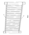
- FIG. 9 is a front elevational view of the assembled fence system of the present invention.
- FIGS. 10 a - 10 e are perspective views of an upper horizontal rail of the fence system of FIG. 9 with various configurations of accent rails;
- FIG. 10 f is perspective view of the lower horizontal rail of the fence systems of FIG. 9 with an accent rail;
- FIGS. 11 a and 11 b are front elevational views illustrating the fence post of FIG. 1 with various configurations of post caps.
- the fence post 1 comprises an inner structural vertical post 2 .
- the inner structural vertical post 2 defines a vertical axis a-a, and includes an upper distal end 4 and a lower distal end 6 .
- the lower distal end 6 comprises a base flange 8 through which the inner structural vertical post 2 is configured to be attached to a generally horizontal surface, e.g. a deck or patio.
- the fence post 1 can be secured to the surface by the base flange 8 .
- carriage bolts and lag bolts insert through the base flange 8 and into the surface to connect the inner structural vertical post 2 to reinforcements 14 .
- An alternative embodiment includes a bolt-on addition that may be used for side mounting and mounting to stringers on stairs.
- a lower insert block 16 as shown in FIGS. 1 and 3 , having a coaxial bore 18 slides over the inner structural vertical post 2 and rests on top of the base flange 8 .
- An outer post 20 comprises a coaxial bore 22 , an upper distal opening 24 , and a lower distal opening 26 .
- the upper and lower distal openings 24 , 26 are dimensioned to slide over the inner structural vertical post 2 and the lower insert block 16 .
- the outer post 20 also includes an upper aperture 28 proximate the upper distal opening 24 and a lower aperture 30 .
- the lower aperture 30 is positioned at a selected height h 1 above the lower distal opening 26 , and the selected height h 1 is substantially equal to the height of the lower insert block 16 .
- the outer post 20 is composed of galvanized and powder coated steel, however, other material may be utilized depending on an intended use of the fence and characteristics required for the fence post 1 .
- a first horizontal rail support 32 is inserted in to a lower aperture 30 at a direction substantially normal to the vertical axis a-a.
- a second horizontal rail support 34 is inserted into an upper aperture 28 at a direction substantially normal to the vertical axis a-a.
- a first portion 36 , 38 of the first and second horizontal rail supports 32 , 34 extend from the exterior 40 of the outer post 20 and a second portion 42 , 44 of the first and second horizontal rail supports, 32 , 34 extend into the interior 46 of the outer post 20 .
- an upper insert block 48 applies downward compressive pressure to the second portion 44 of the second horizontal rail support 34 .
- the lower insert block 16 applies upward compressive pressure to the second portion 42 of the first horizontal rail support 32 .
- both the first and second horizontal rail supports 32 , 34 comprise flanges.
- the first and second horizontal rail supports 32 , 34 are further locked in place with upper and lower locking devices 50 inserted through the respective upper and lower apertures 28 , 30 .
- these locking devices 50 preferably comprise wedges 52 configured to fit on sides of the respective horizontal rail supports 32 , 34 .
- Each wedge 52 has an inner sloped surface, having an angle ⁇ , in contact with a corresponding sloped outer surface of the respective horizontal rail support 32 , 34 , having an angle ⁇ , wherein angles ⁇ and ⁇ are substantially supplementary.
- the horizontal rail supports 32 , 34 include projecting tabs 54 , 56 and the inner surfaces of the wedges 52 include concave slots 58 configured to receive the projecting tabs 53 , 54 .
- the wedges 52 further comprise stops 60 , which when engaged are in contact with the respective horizontal rail supports 32 , 34 .
- decorative caps 62 are inserted into any lower apertures 30 and upper apertures 28 in which no horizontal rail supports are inserted.
- two fence posts can be connected to each other with a lower horizontal rail 64 and upper horizontal rail 66 to create a fence system 68 .
- the lower and upper horizontal rails 64 , 66 have open ends which are inserted over each fence post's upper and lower horizontal rail supports 32 , 34 , respectively, as shown in FIGS. 3-8 .
- the locking device 50 preferably the wedge 52
- the lower and upper horizontal rails 64 , 66 include an opening for the insertion of the locking device 50 .
- Accent rails as shown in FIGS. 10 a - 10 f can be attached to the lower and upper horizontal rails 64 , 66 .
- FIGS. 10 a - f illustrate various options for accent rails for the upper horizontal rail 66 , including no accent rail ( FIG. 10 a ), white vinyl ( FIG. 10 b ), steel powder coated ( FIG. 10 c ), shaped PT wood ( FIG. 10 d ), shaped composite ( FIG. 10 e ), and as well as a nylon accent for the lower horizontal rail 64 ( FIG. 10 f ).
- the process of assembling the fence system 68 is designed to be simple and to result in aesthetically pleasing connections.
- the process for assembling the fence system preferably will be performed in the following sequence of steps, but the invention is not limited to this sequence.
- the fence system 68 can be assembled by attaching the inner structural post 2 to a substantially horizontal surface, for example a deck. This step is repeated as necessary until the desired final fence configuration is achieved, by using each fence post 1 as an end, corner, or straight run fence section.
- the inner structural vertical post 2 is inserted into the coaxial bore 3 of the lower insert block 16 with the lower insert block 16 moving over and around the inner structural vertical post 2 until it is in contact with a substantially horizontal surface or, as in the preferred embodiment, with the base flange 8 .
- the first and second horizontal rail supports 32 , 34 are inserted though the lower and upper apertures 30 , 28 , respectively.
- the first and second horizontal rail supports are inserted from the interior 46 of the outer post 20 to the exterior 40 of the outer post 20 .
- the outer post 20 slides over and around the inner structural vertical post 2 and the lower insert block 16 , so that the inner structural vertical post 2 extends upward within the bore 26 of the outer post 20 and the lower insert block 16 applies an upward compressive force to the second portion 42 of the first horizontal rail support 32 .
- FIG. 6 shows the upper insert block 48 inserted into the upper distal opening 24 of the outer post 20 until it contacts and applies a downward compressive force to the second portion 44 of the second horizontal rail support 34 .
- the open ends of the lower and upper horizontal rails 64 , 66 slide onto the first and second horizontal rail supports 32 , 34 , respectively.
- Another step of the assembly process is locking the upper and lower horizontal rail supports 32 , 34 in place against the upper and lower horizontal rails 66 , 64 .
- this locking step comprises inserting a locking device 50 , or specifically a wedge 52 , between an inner wall of each of the lower and upper horizontal rails 64 , 66 and an outer wall of the corresponding horizontal rail support 32 , 34 . This is further illustrated in FIGS. 7 and 8 a.
- a post cap 70 can be inserted into the upper distal opening 24 of the outer post 20 .
- accent post caps including a pyramid with a ball 72 and a flat top 74 post caps have lower distal openings that slide over the post cap 70 .
- the accent post caps 72 , 74 are held into place with interior teeth 76 .
Abstract
Description
Claims (19)
Priority Applications (1)
| Application Number | Priority Date | Filing Date | Title |
|---|---|---|---|
| US12/805,260 US8505880B2 (en) | 2010-07-21 | 2010-07-21 | Fence rail support system |
Applications Claiming Priority (1)
| Application Number | Priority Date | Filing Date | Title |
|---|---|---|---|
| US12/805,260 US8505880B2 (en) | 2010-07-21 | 2010-07-21 | Fence rail support system |
Publications (2)
| Publication Number | Publication Date |
|---|---|
| US20120018692A1 US20120018692A1 (en) | 2012-01-26 |
| US8505880B2 true US8505880B2 (en) | 2013-08-13 |
Family
ID=45492833
Family Applications (1)
| Application Number | Title | Priority Date | Filing Date |
|---|---|---|---|
| US12/805,260 Active 2030-11-20 US8505880B2 (en) | 2010-07-21 | 2010-07-21 | Fence rail support system |
Country Status (1)
| Country | Link |
|---|---|
| US (1) | US8505880B2 (en) |
Cited By (9)
| Publication number | Priority date | Publication date | Assignee | Title |
|---|---|---|---|---|
| US20150240515A1 (en) * | 2009-03-10 | 2015-08-27 | James E. Davis | Fence/railing post cap system |
| US20170234016A1 (en) * | 2013-10-30 | 2017-08-17 | Barrette Outdoor Living, Inc. | Railing and baluster plug system |
| US20170328070A1 (en) * | 2016-05-16 | 2017-11-16 | Kirby Alan Lane | Core assembly for anchoring and supporting |
| US10301842B2 (en) | 2015-04-16 | 2019-05-28 | Dee Volin | Unique self-locking self-centering bracket-clamp fence system, having self-locking self-centering bracket-clamp system, board-expansion-internal-gap post system, and board-expansion-internal-gap rail system |
| US10385598B2 (en) * | 2018-01-08 | 2019-08-20 | Architectural Builders Hardware Mfg., Inc. | Tip for geared hinge |
| US10428553B2 (en) | 2017-09-21 | 2019-10-01 | Steven Joseph Parenti | Fence post with metal insert |
| US10633899B2 (en) * | 2018-09-28 | 2020-04-28 | Select Products Limited | Multi-piece top cap for a geared continuous hinge |
| US11002050B1 (en) | 2020-01-03 | 2021-05-11 | Select Products Limited | Radial progression hinge cap for a ligature resistant door hinge assembly |
| US11851833B1 (en) * | 2018-06-14 | 2023-12-26 | Ameristar Perimeter Security Usa Inc. | Cable barrier |
Families Citing this family (7)
| Publication number | Priority date | Publication date | Assignee | Title |
|---|---|---|---|---|
| USD749239S1 (en) * | 2013-12-12 | 2016-02-09 | Dee Volin | Top rail end cup |
| USD750808S1 (en) * | 2014-04-09 | 2016-03-01 | Extenday Ip Limited | Post cap |
| CN104314362B (en) * | 2014-10-24 | 2016-06-22 | 张玉恒 | Fully-prefabricated assembled enclosure wall |
| US10190329B2 (en) | 2015-03-18 | 2019-01-29 | Jacob Kobelt | Methods, systems, and assemblies for covering an end of a post |
| WO2017102024A1 (en) | 2015-12-18 | 2017-06-22 | Volvo Truck Corporation | A method for controlling a safety system in a vehicle using an electric road system |
| US10604957B1 (en) * | 2018-12-22 | 2020-03-31 | Peter Pulizzi | Safety apparatus |
| US11208818B1 (en) * | 2020-02-19 | 2021-12-28 | Peter Pulizzi | Safety apparatus |
Citations (171)
| Publication number | Priority date | Publication date | Assignee | Title |
|---|---|---|---|---|
| US313825A (en) | 1885-03-10 | Iron fence | ||
| US502840A (en) | 1893-08-08 | Joint for fences | ||
| US803741A (en) | 1905-02-14 | 1905-11-07 | Ole Carlson | Corner shield or protector. |
| US895297A (en) | 1908-08-04 | Francis A Peter | Iron fence. | |
| US1630492A (en) | 1924-06-09 | 1927-05-31 | Simmons Co | Connection for tubes |
| US1757686A (en) | 1929-10-28 | 1930-05-06 | Rosenbaum Gad | Stair and baluster railing |
| US1796175A (en) | 1929-07-10 | 1931-03-10 | Winston James | Metal-stair construction |
| US2218953A (en) | 1939-08-07 | 1940-10-22 | Cyclone Fence Company | Adjustable grade iron fence |
| US2218954A (en) | 1939-08-07 | 1940-10-22 | Cyclone Fence Company | Adjustable grade iron fence |
| US2327311A (en) | 1941-02-24 | 1943-08-17 | Lundy Robert | Fence structure |
| US2427723A (en) | 1944-09-25 | 1947-09-23 | Floyd L Hawkins | Ornamental balustrade |
| US2482592A (en) | 1944-09-16 | 1949-09-20 | Diebold Inc | Metal door construction |
| US2558142A (en) | 1947-01-21 | 1951-06-26 | William A Lapp | Iron railing |
| US2563529A (en) | 1951-08-07 | Metal balustrade | ||
| US2563530A (en) | 1951-08-07 | Balustrade | ||
| US2576427A (en) | 1950-05-09 | 1951-11-27 | Robert E Tomb | Knockdown porch and step railing |
| US2590929A (en) | 1947-11-19 | 1952-04-01 | William W Bush | Railing |
| US2654579A (en) | 1950-02-25 | 1953-10-06 | Leroy W Cremens | Railing |
| US2655345A (en) | 1948-04-22 | 1953-10-13 | Philip C Lindman | Ornamental ironwork structure |
| US2687283A (en) | 1953-09-02 | 1954-08-24 | Winford L Enghauser | Interchangeable fence and guard rail section |
| US2715513A (en) | 1953-04-17 | 1955-08-16 | Kools Brothers Inc | Adjustable railing section |
| US2840349A (en) | 1955-10-14 | 1958-06-24 | Edward E Raymond | Ornamental aluminum railing |
| US2855227A (en) | 1954-09-20 | 1958-10-07 | John R Bottom | Railing assembly |
| US2909361A (en) | 1955-01-31 | 1959-10-20 | Leighton G Dotson | Ornamental ironwork structures |
| US2932488A (en) | 1957-06-04 | 1960-04-12 | Leighton G Dotson | Building structures |
| US3033532A (en) | 1960-05-23 | 1962-05-08 | Mcfall Harry | Railing construction |
| US3067985A (en) | 1961-03-29 | 1962-12-11 | Westmoreland Metal Mfg Co | Picket fence |
| US3083951A (en) | 1960-05-12 | 1963-04-02 | Locke Mfg Company | Interlocking ornamental railing |
| US3113760A (en) | 1960-01-29 | 1963-12-10 | Locke Mfg Company | Interlocking ornamental railing |
| US3202401A (en) | 1963-04-01 | 1965-08-24 | Bastia Paul | Balustrade |
| US3204898A (en) | 1964-02-17 | 1965-09-07 | Product Engineering Company | Adjustable support |
| US3240297A (en) | 1963-12-30 | 1966-03-15 | Wilfrid J Desy | Corner construction |
| US3244406A (en) | 1962-01-24 | 1966-04-05 | Louis J Garofola | Joint for a structural assembly |
| US3258251A (en) | 1964-10-12 | 1966-06-28 | Culter Norman | Knockdown adjustable railing construction |
| US3278209A (en) | 1964-04-22 | 1966-10-11 | Winikoff Sydney | Coupling means for tubular members |
| US3306586A (en) | 1965-07-13 | 1967-02-28 | George E Green | Adjustable railing |
| US3315943A (en) | 1964-04-28 | 1967-04-25 | Sylvan Pools Inc | Modular metal picket fence construction |
| US3343811A (en) | 1965-10-11 | 1967-09-26 | Edward J Kusel | Heavy duty adjustable railing |
| US3385567A (en) | 1965-11-05 | 1968-05-28 | Reynolds Metals Co | Railing constructions and parts therefor or the like |
| US3414236A (en) | 1966-08-18 | 1968-12-03 | Kenron Aluminum & Glass Corp | Hand rail |
| US3420013A (en) | 1966-07-01 | 1969-01-07 | Alvarado Mfg Co Inc | Post construction |
| US3506999A (en) | 1968-08-05 | 1970-04-21 | Mc Donnell Douglas Corp | Fair-lead grommet |
| US3529808A (en) | 1969-06-30 | 1970-09-22 | Kools Brothers Inc | Adjustable railing assembly |
| US3596880A (en) | 1968-12-17 | 1971-08-03 | American Metal Prod | Railing system |
| US3648982A (en) | 1970-07-06 | 1972-03-14 | Arnold Sabel | Railing connector |
| US3704005A (en) | 1971-05-27 | 1972-11-28 | Questor Corp | Tubular spindle having deformable flattened ends |
| US3707276A (en) | 1971-11-05 | 1972-12-26 | Superior Aluminum Products Inc | Simplified relatively heavy duty railing construction |
| US3854192A (en) | 1973-08-03 | 1974-12-17 | Wheeling Pittsburgh Steel Corp | Method of attaching lateral bracing to metal studding |
| US3858850A (en) | 1973-08-21 | 1975-01-07 | W T Ind Inc | Adjustable picket rail assembly for stairways |
| US3942763A (en) | 1974-02-04 | 1976-03-09 | A-T-O Inc. | Adjustable wrought iron railing assembly |
| US3960367A (en) | 1975-05-12 | 1976-06-01 | Spacemaker (Products) Limited | Fence with adjustable vertical panels |
| US4047702A (en) * | 1975-02-12 | 1977-09-13 | Snam Progetti S.P.A. | Device for absorbing impact energy |
| US4238117A (en) | 1978-08-31 | 1980-12-09 | Don Newman | Railing and method of making the same |
| US4272061A (en) | 1979-11-28 | 1981-06-09 | Suckno Brothers Company | Variable pitch rail system |
| US4360285A (en) | 1981-01-09 | 1982-11-23 | Magness Howard A | Rail and post connector |
| US4403767A (en) | 1980-12-29 | 1983-09-13 | Gene Basey | Variable rack stair rail assembly |
| US4421302A (en) | 1981-01-30 | 1983-12-20 | Grimm William G | Prefabricated adjustable handrail assembly |
| GB2093513B (en) | 1981-02-25 | 1984-11-28 | Malkmus Doernemann Carola | Sliding gate |
| US4533121A (en) | 1980-06-06 | 1985-08-06 | Gene Basey | Variable pitch stair railing assembly |
| US4690440A (en) | 1985-12-30 | 1987-09-01 | Rogers Gerald H | Strengthened latch and striker bar structure for fence gates |
| US4723760A (en) | 1987-05-14 | 1988-02-09 | Sullivan William O | Picket fence assembly |
| US4786203A (en) | 1987-09-16 | 1988-11-22 | Allied Tube & Conduit Corporation | Connector assembly for food preparation equipment and method of assembly |
| US4871203A (en) | 1988-01-04 | 1989-10-03 | J & J Hardware, Inc. | Reversible mount gate latch with manual latch locking |
| US4883256A (en) | 1989-01-23 | 1989-11-28 | Hebda Thomas J | Picket fence and method of construction |
| US4886245A (en) | 1987-01-20 | 1989-12-12 | Louis Manzo | Interlocking pivot device for adjustable ballusters |
| US4898365A (en) | 1987-08-20 | 1990-02-06 | Allied Tube & Conduit Corporation | Modular barrier |
| US4917284A (en) | 1987-09-22 | 1990-04-17 | Monolite S.R.L. | Apparatus for manufacturing building panels |
| US4928930A (en) | 1989-11-02 | 1990-05-29 | Chung Yu Kuei | Balustrade |
| US4972642A (en) | 1990-01-03 | 1990-11-27 | Strobl Jr Frederick P | Footings for post or beam construction |
| US4982933A (en) | 1988-01-28 | 1991-01-08 | Harbor Towne Fence, Inc. | Fence connector clip and assembly |
| US5029820A (en) | 1989-08-04 | 1991-07-09 | Robern, Inc. | Wedge-adjustable base for rail posts and the like |
| US5056283A (en) | 1990-06-06 | 1991-10-15 | Visador Company | Adjustable stair rail |
| US5136813A (en) | 1991-09-23 | 1992-08-11 | Fence Hardware Specialties, Inc. Dba Ameristar Fence Products | Cantilever-type sliding gate |
| US5167049A (en) | 1991-10-15 | 1992-12-01 | Fence Hardware Specialties, Inc. | Square frame hinge |
| US5190268A (en) | 1991-10-25 | 1993-03-02 | Espinueva Belarmino G | Fence construction system for sloping terrain |
| US5200240A (en) | 1991-05-02 | 1993-04-06 | Baker Neill E | Aluminum railing apparatus |
| US5255897A (en) | 1991-03-11 | 1993-10-26 | Bemis Manufacturing Company | Modular fence |
| US5340087A (en) | 1991-01-12 | 1994-08-23 | The Northern Joinery Limited | Balustrades |
| US5372354A (en) | 1993-07-28 | 1994-12-13 | Cacicedo; Paulino A. | Picket fence permitting adjacent sections to be oriented angularly |
| US5383739A (en) | 1993-06-15 | 1995-01-24 | Haglund; Vernon | Variable angle post for coupling fence segments |
| US5419538A (en) | 1994-03-18 | 1995-05-30 | Nicholson; Thomas N. | Newel post fastening system |
| US5437433A (en) | 1993-09-28 | 1995-08-01 | Lavi Industries, Inc. | Adjustable stair rail system |
| US5443244A (en) | 1993-03-22 | 1995-08-22 | Gibbs; Edward L. | Rolled metal fence rail |
| US5454548A (en) | 1994-02-25 | 1995-10-03 | Moore; Robert S. | Modular metal fencing and gratings employing novel fastening means for reduction of assembly time |
| US5547169A (en) | 1994-11-10 | 1996-08-20 | The Anchor Group | Fence assembly with swivel bracket |
| US5556079A (en) | 1995-05-01 | 1996-09-17 | West; Ronald R. | Fencing system with mounting clips |
| US5649688A (en) | 1995-02-17 | 1997-07-22 | Baker; Neill E. | Railings with continuous spacers |
| US5660378A (en) | 1996-06-27 | 1997-08-26 | Delair Group Llc | Fence assembly |
| US5820111A (en) | 1996-11-05 | 1998-10-13 | Ross; Nancy A. | Modular stairway and balcony railing system |
| US5873671A (en) | 1997-02-19 | 1999-02-23 | Kroy Building Products, Inc. | Rail attachment bracket with snap-on cover |
| US5873564A (en) | 1994-11-25 | 1999-02-23 | Bisch; Robert M. | Method and apparatus for constructing a metal picket fence |
| US5882001A (en) | 1997-07-31 | 1999-03-16 | Reinbold; James F. | Modular fence structure |
| US5896721A (en) | 1996-11-19 | 1999-04-27 | West Company Limited | Metal device for joining wooden members in wooden building |
| US5957424A (en) | 1996-04-01 | 1999-09-28 | Klaus Krinner | Device for the vertical arrangement of a pole or post-like object |
| US5971365A (en) | 1997-11-21 | 1999-10-26 | Pigott; Patrick C. | Fence construction |
| US5984587A (en) | 1997-11-06 | 1999-11-16 | Odle; Stanley W. | Ground stabilization apparatus and method for installing an enlongated post |
| US6029954A (en) | 1997-03-18 | 2000-02-29 | Murdaca; Domenico | Railing assembly |
| US6126145A (en) | 1997-11-07 | 2000-10-03 | Mohr; Sylvia Ann | Fence with adjustable pickets and readily dismantlable |
| US6176043B1 (en) | 1999-01-14 | 2001-01-23 | Edward L. Gibbs | PVC gate framing system |
| US6176053B1 (en) | 1998-08-27 | 2001-01-23 | Roger C. A. St. Germain | Wall track assembly and method for installing the same |
| US6189277B1 (en) | 1998-12-07 | 2001-02-20 | Palo Verde Drywall, Inc. | Firestop cavity occlusion for metallic stud framing |
| US6199336B1 (en) | 1999-03-11 | 2001-03-13 | California Expanded Metal Products Company | Metal wall framework and clip |
| US6254064B1 (en) | 1999-05-18 | 2001-07-03 | Edward L. Gibbs | Ornamental ring for fence |
| US6299143B1 (en) | 1999-01-26 | 2001-10-09 | Valentine & Company | Coupling spool |
| US6305670B1 (en) | 1996-10-22 | 2001-10-23 | Larry E. Ward | Railing assembly |
| US6308937B1 (en) | 1999-11-30 | 2001-10-30 | Gsw Inc. | Railing system |
| US6311957B1 (en) | 1997-06-19 | 2001-11-06 | Custom Iron, Inc. | Device and method for attaching balusters |
| US6341764B1 (en) | 1999-04-20 | 2002-01-29 | Allied Tubing & Conduit Corporation | Fence system |
| US6345809B1 (en) * | 1999-05-11 | 2002-02-12 | Ronald William Bebendorf | Fence panel |
| US6375166B1 (en) | 2000-03-24 | 2002-04-23 | Delair Group, Inc. | Fence which eliminates the need for conventional fasteners |
| US6460829B1 (en) | 1999-01-15 | 2002-10-08 | Kroy Building Products, Inc. | Fence system with variable position rail |
| USD465856S1 (en) | 2002-03-29 | 2002-11-19 | Edward L. Gibbs | Fence rail |
| US20030146426A1 (en) | 2002-01-12 | 2003-08-07 | Ray Susan R. | Portable collapsible corral fence and method of use |
| US20030151039A1 (en) | 2002-02-12 | 2003-08-14 | Zen Paul Robert | Railing system |
| US6612087B2 (en) | 2000-11-29 | 2003-09-02 | The Steel Network, Inc. | Building member connector allowing bi-directional relative movement |
| US6631887B1 (en) | 2001-05-14 | 2003-10-14 | Roger Walmsley | Vertical fencing |
| US6648304B1 (en) | 2002-03-01 | 2003-11-18 | Xcel Distribution, Inc. | Modular fence |
| US6682056B1 (en) | 2000-03-24 | 2004-01-27 | Kroy Building Products, Inc. | Mounting clip with locking feature |
| US6698726B2 (en) | 2002-01-24 | 2004-03-02 | Robert E. Platt | Rail clip |
| US6739583B2 (en) | 2001-10-05 | 2004-05-25 | David Allen Ryon | Metal fence rail |
| US6752386B1 (en) | 2003-05-13 | 2004-06-22 | Donald Eugene Bundy | Fence with sliding lock bar |
| USD495434S1 (en) | 2003-05-28 | 2004-08-31 | 440 Fence Company, Inc. | Fence post coupling device |
| US6802496B1 (en) | 2002-12-09 | 2004-10-12 | John Preta | Fence bracket system and fence system using the fence bracket system |
| US6811145B2 (en) | 2002-05-07 | 2004-11-02 | Edward L. Gibbs | Barrier formed by resistance projection welding |
| US6824123B2 (en) | 2001-05-24 | 2004-11-30 | Master-Halco, Inc. | Picket fence and rail mounting system |
| US6874767B1 (en) | 2002-04-05 | 2005-04-05 | Fence | |
| US6883786B2 (en) | 2001-06-05 | 2005-04-26 | Ronald William Bebendorf | Fence post and rail assembly with concealed strengthening bars |
| US6889960B1 (en) | 2003-11-14 | 2005-05-10 | Kelly D Jones | Connectors and railing system having metal balusters isolated from corrosion |
| US20050205854A1 (en) | 2004-03-15 | 2005-09-22 | Edward Gibbs | Fence with tiltable picket |
| US6969051B1 (en) | 2002-11-22 | 2005-11-29 | Gibbs Edward L | Two-part rail with internal picket connection |
| US7021607B1 (en) | 2001-12-15 | 2006-04-04 | James Alexander | Fence construction system |
| US7025335B2 (en) | 2002-03-01 | 2006-04-11 | Alan Qing Zhu | Modular fence |
| US7077386B1 (en) | 2002-04-09 | 2006-07-18 | Harris Trust And Savings Bank | Adjustable staircase rail system |
| US20060169965A1 (en) | 2005-01-31 | 2006-08-03 | Paskar Stanley M | Pre-fabricated fencing panels |
| US7086642B1 (en) | 2000-12-26 | 2006-08-08 | Xfm, Inc. | Rackabale gate for fence and method of producing such |
| US7090202B1 (en) | 2000-12-26 | 2006-08-15 | Xfm, Inc. | Fence and method of producing such |
| US7100904B2 (en) | 2002-04-12 | 2006-09-05 | New Green Chang Shin Co., Ltd. | Adaptable fence |
| US7134646B1 (en) | 2004-09-14 | 2006-11-14 | Brooks Roy C | Privacy fence system |
| USD534792S1 (en) | 2004-08-10 | 2007-01-09 | 440 Fence Company, Inc. | Fence post coupler |
| US7188826B1 (en) | 2004-11-20 | 2007-03-13 | Gibbs Edward L | Internal clip for a rail |
| US7232114B2 (en) * | 2005-06-02 | 2007-06-19 | Platt Robert E | Fence assembly with rail clip for use therewith |
| US7243473B2 (en) | 2002-08-06 | 2007-07-17 | Terrels Christopher J | Post assembly and trim ring |
| US7306203B2 (en) | 2005-01-28 | 2007-12-11 | Platt Robert E | Post assembly and spacer for use therewith |
| US7325787B1 (en) | 2004-11-01 | 2008-02-05 | Gibbs Edward L | Barrier |
| US7341242B2 (en) | 2004-09-13 | 2008-03-11 | Bertato Maurizio C | Fence system |
| US7360754B2 (en) | 2006-03-23 | 2008-04-22 | Robbins Steven L | Interlocking fence system and method |
| US7384025B2 (en) | 2005-10-18 | 2008-06-10 | Chong-Yi Lo | Screw hiding device for combining lateral tubes with upright tubes |
| USD572374S1 (en) | 2004-01-26 | 2008-07-01 | Gibbs Edward L | Cable-reinforced bollard fence |
| US7396002B1 (en) | 2006-05-16 | 2008-07-08 | Gibbs Edward L | Terrain-adjustable bracket |
| US7407152B2 (en) | 2005-01-28 | 2008-08-05 | Platt Robert E | Fencing system and post insert for use therewith |
| US7434789B2 (en) | 2005-12-08 | 2008-10-14 | Allied Tube & Conduit Corp. | Picket fence assembly |
| US7445196B2 (en) | 2002-02-20 | 2008-11-04 | Universal Consumer Products, Inc. | Plastic fencing simulative of wrought iron |
| US7475870B2 (en) | 2005-12-22 | 2009-01-13 | Platt Robert E | Method and apparatus for mounting angled fence portions |
| US7475868B1 (en) | 2002-04-05 | 2009-01-13 | Gibbs Edward L | Cable fence system |
| US7478799B2 (en) | 2006-10-19 | 2009-01-20 | Viviano Robert P | Railing system |
| US20090065755A1 (en) | 2007-09-06 | 2009-03-12 | Fortress Iron, Lp | Barrier system |
| US7503551B2 (en) | 2003-12-18 | 2009-03-17 | Crimp Tech Industries | Fence construction systems |
| US7530550B2 (en) * | 2007-05-03 | 2009-05-12 | Lmt-Mercer Group Inc. | Apparatus and method for post mount guide |
| US20090238640A1 (en) | 2008-03-19 | 2009-09-24 | Jerith Manufacturing Company, Inc. | Fence clip |
| US7635115B2 (en) | 2006-02-01 | 2009-12-22 | Ideal Aluminum Products, Llc | Protective cover for fence rail cap |
| US7661656B1 (en) | 2007-01-30 | 2010-02-16 | Gibbs Edward L | Barbed tape |
| US7677535B1 (en) | 2008-09-16 | 2010-03-16 | Chong-Yi Lo | Railing |
| US20100155683A1 (en) | 2008-12-19 | 2010-06-24 | Payne John F | Rackable Fence System |
| US7762533B2 (en) | 2002-07-03 | 2010-07-27 | Elk Premium Building Products, Inc. | Fasteners, railing system and method of assembly |
| US20100200827A1 (en) | 2009-02-09 | 2010-08-12 | Gordon Duffy | Fence/rail assembly with concealed sliding, pivotal connection, and manufacturing method therefor |
| US20100237308A1 (en) | 2009-03-23 | 2010-09-23 | Chong-Yi Lo | Fence |
| US20100252793A1 (en) | 2009-04-06 | 2010-10-07 | Ash Gary W | Fence rail with concealed fastener |
| US20100276653A1 (en) | 2009-04-30 | 2010-11-04 | Gibbs Edward L | Extruded Aluminum Rail |
| US20110001105A1 (en) | 2009-07-02 | 2011-01-06 | Chong-Yi Lo | Hidden-Fastener fence |
| US7971412B1 (en) | 2008-09-09 | 2011-07-05 | S.V. International Corp. | Baluster system and method |
| US7992362B2 (en) | 2009-02-13 | 2011-08-09 | Alpa Lumber Inc. | Column assembly |
-
2010
- 2010-07-21 US US12/805,260 patent/US8505880B2/en active Active
Patent Citations (182)
| Publication number | Priority date | Publication date | Assignee | Title |
|---|---|---|---|---|
| US313825A (en) | 1885-03-10 | Iron fence | ||
| US502840A (en) | 1893-08-08 | Joint for fences | ||
| US895297A (en) | 1908-08-04 | Francis A Peter | Iron fence. | |
| US2563530A (en) | 1951-08-07 | Balustrade | ||
| US2563529A (en) | 1951-08-07 | Metal balustrade | ||
| US803741A (en) | 1905-02-14 | 1905-11-07 | Ole Carlson | Corner shield or protector. |
| US1630492A (en) | 1924-06-09 | 1927-05-31 | Simmons Co | Connection for tubes |
| US1796175A (en) | 1929-07-10 | 1931-03-10 | Winston James | Metal-stair construction |
| US1757686A (en) | 1929-10-28 | 1930-05-06 | Rosenbaum Gad | Stair and baluster railing |
| US2218954A (en) | 1939-08-07 | 1940-10-22 | Cyclone Fence Company | Adjustable grade iron fence |
| US2218953A (en) | 1939-08-07 | 1940-10-22 | Cyclone Fence Company | Adjustable grade iron fence |
| US2327311A (en) | 1941-02-24 | 1943-08-17 | Lundy Robert | Fence structure |
| US2482592A (en) | 1944-09-16 | 1949-09-20 | Diebold Inc | Metal door construction |
| US2427723A (en) | 1944-09-25 | 1947-09-23 | Floyd L Hawkins | Ornamental balustrade |
| US2558142A (en) | 1947-01-21 | 1951-06-26 | William A Lapp | Iron railing |
| US2590929A (en) | 1947-11-19 | 1952-04-01 | William W Bush | Railing |
| US2655345A (en) | 1948-04-22 | 1953-10-13 | Philip C Lindman | Ornamental ironwork structure |
| US2654579A (en) | 1950-02-25 | 1953-10-06 | Leroy W Cremens | Railing |
| US2576427A (en) | 1950-05-09 | 1951-11-27 | Robert E Tomb | Knockdown porch and step railing |
| US2715513A (en) | 1953-04-17 | 1955-08-16 | Kools Brothers Inc | Adjustable railing section |
| US2687283A (en) | 1953-09-02 | 1954-08-24 | Winford L Enghauser | Interchangeable fence and guard rail section |
| US2855227A (en) | 1954-09-20 | 1958-10-07 | John R Bottom | Railing assembly |
| US2909361A (en) | 1955-01-31 | 1959-10-20 | Leighton G Dotson | Ornamental ironwork structures |
| US2840349A (en) | 1955-10-14 | 1958-06-24 | Edward E Raymond | Ornamental aluminum railing |
| US2932488A (en) | 1957-06-04 | 1960-04-12 | Leighton G Dotson | Building structures |
| US3113760A (en) | 1960-01-29 | 1963-12-10 | Locke Mfg Company | Interlocking ornamental railing |
| US3083951A (en) | 1960-05-12 | 1963-04-02 | Locke Mfg Company | Interlocking ornamental railing |
| US3033532A (en) | 1960-05-23 | 1962-05-08 | Mcfall Harry | Railing construction |
| US3067985A (en) | 1961-03-29 | 1962-12-11 | Westmoreland Metal Mfg Co | Picket fence |
| US3244406A (en) | 1962-01-24 | 1966-04-05 | Louis J Garofola | Joint for a structural assembly |
| US3202401A (en) | 1963-04-01 | 1965-08-24 | Bastia Paul | Balustrade |
| US3240297A (en) | 1963-12-30 | 1966-03-15 | Wilfrid J Desy | Corner construction |
| US3204898A (en) | 1964-02-17 | 1965-09-07 | Product Engineering Company | Adjustable support |
| US3278209A (en) | 1964-04-22 | 1966-10-11 | Winikoff Sydney | Coupling means for tubular members |
| US3315943A (en) | 1964-04-28 | 1967-04-25 | Sylvan Pools Inc | Modular metal picket fence construction |
| US3258251A (en) | 1964-10-12 | 1966-06-28 | Culter Norman | Knockdown adjustable railing construction |
| US3306586A (en) | 1965-07-13 | 1967-02-28 | George E Green | Adjustable railing |
| US3343811A (en) | 1965-10-11 | 1967-09-26 | Edward J Kusel | Heavy duty adjustable railing |
| US3385567A (en) | 1965-11-05 | 1968-05-28 | Reynolds Metals Co | Railing constructions and parts therefor or the like |
| US3420013A (en) | 1966-07-01 | 1969-01-07 | Alvarado Mfg Co Inc | Post construction |
| US3414236A (en) | 1966-08-18 | 1968-12-03 | Kenron Aluminum & Glass Corp | Hand rail |
| US3506999A (en) | 1968-08-05 | 1970-04-21 | Mc Donnell Douglas Corp | Fair-lead grommet |
| US3596880A (en) | 1968-12-17 | 1971-08-03 | American Metal Prod | Railing system |
| US3529808A (en) | 1969-06-30 | 1970-09-22 | Kools Brothers Inc | Adjustable railing assembly |
| US3648982A (en) | 1970-07-06 | 1972-03-14 | Arnold Sabel | Railing connector |
| US3704005A (en) | 1971-05-27 | 1972-11-28 | Questor Corp | Tubular spindle having deformable flattened ends |
| US3707276A (en) | 1971-11-05 | 1972-12-26 | Superior Aluminum Products Inc | Simplified relatively heavy duty railing construction |
| US3854192A (en) | 1973-08-03 | 1974-12-17 | Wheeling Pittsburgh Steel Corp | Method of attaching lateral bracing to metal studding |
| US3858850A (en) | 1973-08-21 | 1975-01-07 | W T Ind Inc | Adjustable picket rail assembly for stairways |
| US3942763A (en) | 1974-02-04 | 1976-03-09 | A-T-O Inc. | Adjustable wrought iron railing assembly |
| US4047702A (en) * | 1975-02-12 | 1977-09-13 | Snam Progetti S.P.A. | Device for absorbing impact energy |
| US3960367A (en) | 1975-05-12 | 1976-06-01 | Spacemaker (Products) Limited | Fence with adjustable vertical panels |
| US4238117A (en) | 1978-08-31 | 1980-12-09 | Don Newman | Railing and method of making the same |
| US4272061A (en) | 1979-11-28 | 1981-06-09 | Suckno Brothers Company | Variable pitch rail system |
| US4533121A (en) | 1980-06-06 | 1985-08-06 | Gene Basey | Variable pitch stair railing assembly |
| US4403767A (en) | 1980-12-29 | 1983-09-13 | Gene Basey | Variable rack stair rail assembly |
| US4360285A (en) | 1981-01-09 | 1982-11-23 | Magness Howard A | Rail and post connector |
| US4421302A (en) | 1981-01-30 | 1983-12-20 | Grimm William G | Prefabricated adjustable handrail assembly |
| GB2093513B (en) | 1981-02-25 | 1984-11-28 | Malkmus Doernemann Carola | Sliding gate |
| US4690440A (en) | 1985-12-30 | 1987-09-01 | Rogers Gerald H | Strengthened latch and striker bar structure for fence gates |
| US4886245A (en) | 1987-01-20 | 1989-12-12 | Louis Manzo | Interlocking pivot device for adjustable ballusters |
| US4723760A (en) | 1987-05-14 | 1988-02-09 | Sullivan William O | Picket fence assembly |
| US4898365A (en) | 1987-08-20 | 1990-02-06 | Allied Tube & Conduit Corporation | Modular barrier |
| US4786203A (en) | 1987-09-16 | 1988-11-22 | Allied Tube & Conduit Corporation | Connector assembly for food preparation equipment and method of assembly |
| US4917284A (en) | 1987-09-22 | 1990-04-17 | Monolite S.R.L. | Apparatus for manufacturing building panels |
| US4871203A (en) | 1988-01-04 | 1989-10-03 | J & J Hardware, Inc. | Reversible mount gate latch with manual latch locking |
| US4982933A (en) | 1988-01-28 | 1991-01-08 | Harbor Towne Fence, Inc. | Fence connector clip and assembly |
| US4883256A (en) | 1989-01-23 | 1989-11-28 | Hebda Thomas J | Picket fence and method of construction |
| US5029820A (en) | 1989-08-04 | 1991-07-09 | Robern, Inc. | Wedge-adjustable base for rail posts and the like |
| US4928930A (en) | 1989-11-02 | 1990-05-29 | Chung Yu Kuei | Balustrade |
| US4972642A (en) | 1990-01-03 | 1990-11-27 | Strobl Jr Frederick P | Footings for post or beam construction |
| US5056283A (en) | 1990-06-06 | 1991-10-15 | Visador Company | Adjustable stair rail |
| US5340087A (en) | 1991-01-12 | 1994-08-23 | The Northern Joinery Limited | Balustrades |
| US5255897A (en) | 1991-03-11 | 1993-10-26 | Bemis Manufacturing Company | Modular fence |
| US5200240A (en) | 1991-05-02 | 1993-04-06 | Baker Neill E | Aluminum railing apparatus |
| US5136813A (en) | 1991-09-23 | 1992-08-11 | Fence Hardware Specialties, Inc. Dba Ameristar Fence Products | Cantilever-type sliding gate |
| US5167049A (en) | 1991-10-15 | 1992-12-01 | Fence Hardware Specialties, Inc. | Square frame hinge |
| US5190268A (en) | 1991-10-25 | 1993-03-02 | Espinueva Belarmino G | Fence construction system for sloping terrain |
| US5443244A (en) | 1993-03-22 | 1995-08-22 | Gibbs; Edward L. | Rolled metal fence rail |
| US5383739A (en) | 1993-06-15 | 1995-01-24 | Haglund; Vernon | Variable angle post for coupling fence segments |
| US5372354A (en) | 1993-07-28 | 1994-12-13 | Cacicedo; Paulino A. | Picket fence permitting adjacent sections to be oriented angularly |
| US5437433A (en) | 1993-09-28 | 1995-08-01 | Lavi Industries, Inc. | Adjustable stair rail system |
| US5454548A (en) | 1994-02-25 | 1995-10-03 | Moore; Robert S. | Modular metal fencing and gratings employing novel fastening means for reduction of assembly time |
| US5419538A (en) | 1994-03-18 | 1995-05-30 | Nicholson; Thomas N. | Newel post fastening system |
| US5547169A (en) | 1994-11-10 | 1996-08-20 | The Anchor Group | Fence assembly with swivel bracket |
| US5873564A (en) | 1994-11-25 | 1999-02-23 | Bisch; Robert M. | Method and apparatus for constructing a metal picket fence |
| US5649688A (en) | 1995-02-17 | 1997-07-22 | Baker; Neill E. | Railings with continuous spacers |
| US5556079A (en) | 1995-05-01 | 1996-09-17 | West; Ronald R. | Fencing system with mounting clips |
| US5957424A (en) | 1996-04-01 | 1999-09-28 | Klaus Krinner | Device for the vertical arrangement of a pole or post-like object |
| US5660378A (en) | 1996-06-27 | 1997-08-26 | Delair Group Llc | Fence assembly |
| US6305670B1 (en) | 1996-10-22 | 2001-10-23 | Larry E. Ward | Railing assembly |
| US5820111A (en) | 1996-11-05 | 1998-10-13 | Ross; Nancy A. | Modular stairway and balcony railing system |
| US5896721A (en) | 1996-11-19 | 1999-04-27 | West Company Limited | Metal device for joining wooden members in wooden building |
| US5873671A (en) | 1997-02-19 | 1999-02-23 | Kroy Building Products, Inc. | Rail attachment bracket with snap-on cover |
| US6029954A (en) | 1997-03-18 | 2000-02-29 | Murdaca; Domenico | Railing assembly |
| US6311957B1 (en) | 1997-06-19 | 2001-11-06 | Custom Iron, Inc. | Device and method for attaching balusters |
| US5882001A (en) | 1997-07-31 | 1999-03-16 | Reinbold; James F. | Modular fence structure |
| US5984587A (en) | 1997-11-06 | 1999-11-16 | Odle; Stanley W. | Ground stabilization apparatus and method for installing an enlongated post |
| US6126145A (en) | 1997-11-07 | 2000-10-03 | Mohr; Sylvia Ann | Fence with adjustable pickets and readily dismantlable |
| US5971365A (en) | 1997-11-21 | 1999-10-26 | Pigott; Patrick C. | Fence construction |
| US6176053B1 (en) | 1998-08-27 | 2001-01-23 | Roger C. A. St. Germain | Wall track assembly and method for installing the same |
| US6189277B1 (en) | 1998-12-07 | 2001-02-20 | Palo Verde Drywall, Inc. | Firestop cavity occlusion for metallic stud framing |
| US6176043B1 (en) | 1999-01-14 | 2001-01-23 | Edward L. Gibbs | PVC gate framing system |
| US6460829B1 (en) | 1999-01-15 | 2002-10-08 | Kroy Building Products, Inc. | Fence system with variable position rail |
| US6299143B1 (en) | 1999-01-26 | 2001-10-09 | Valentine & Company | Coupling spool |
| US6199336B1 (en) | 1999-03-11 | 2001-03-13 | California Expanded Metal Products Company | Metal wall framework and clip |
| US6341764B1 (en) | 1999-04-20 | 2002-01-29 | Allied Tubing & Conduit Corporation | Fence system |
| US6345809B1 (en) * | 1999-05-11 | 2002-02-12 | Ronald William Bebendorf | Fence panel |
| US6254064B1 (en) | 1999-05-18 | 2001-07-03 | Edward L. Gibbs | Ornamental ring for fence |
| US6308937B1 (en) | 1999-11-30 | 2001-10-30 | Gsw Inc. | Railing system |
| US6682056B1 (en) | 2000-03-24 | 2004-01-27 | Kroy Building Products, Inc. | Mounting clip with locking feature |
| US6375166B1 (en) | 2000-03-24 | 2002-04-23 | Delair Group, Inc. | Fence which eliminates the need for conventional fasteners |
| US6612087B2 (en) | 2000-11-29 | 2003-09-02 | The Steel Network, Inc. | Building member connector allowing bi-directional relative movement |
| US7090202B1 (en) | 2000-12-26 | 2006-08-15 | Xfm, Inc. | Fence and method of producing such |
| US7086642B1 (en) | 2000-12-26 | 2006-08-08 | Xfm, Inc. | Rackabale gate for fence and method of producing such |
| US6631887B1 (en) | 2001-05-14 | 2003-10-14 | Roger Walmsley | Vertical fencing |
| US6824123B2 (en) | 2001-05-24 | 2004-11-30 | Master-Halco, Inc. | Picket fence and rail mounting system |
| US6883786B2 (en) | 2001-06-05 | 2005-04-26 | Ronald William Bebendorf | Fence post and rail assembly with concealed strengthening bars |
| US6739583B2 (en) | 2001-10-05 | 2004-05-25 | David Allen Ryon | Metal fence rail |
| US7021607B1 (en) | 2001-12-15 | 2006-04-04 | James Alexander | Fence construction system |
| US20030146426A1 (en) | 2002-01-12 | 2003-08-07 | Ray Susan R. | Portable collapsible corral fence and method of use |
| US6698726B2 (en) | 2002-01-24 | 2004-03-02 | Robert E. Platt | Rail clip |
| US6752385B2 (en) | 2002-02-12 | 2004-06-22 | Paul Robert Zen | Railing system |
| US20030151039A1 (en) | 2002-02-12 | 2003-08-14 | Zen Paul Robert | Railing system |
| US7445196B2 (en) | 2002-02-20 | 2008-11-04 | Universal Consumer Products, Inc. | Plastic fencing simulative of wrought iron |
| US7347412B1 (en) | 2002-03-01 | 2008-03-25 | Alan Qing-Lin Zhu | Modular fence |
| US6648304B1 (en) | 2002-03-01 | 2003-11-18 | Xcel Distribution, Inc. | Modular fence |
| US7025335B2 (en) | 2002-03-01 | 2006-04-11 | Alan Qing Zhu | Modular fence |
| USD465856S1 (en) | 2002-03-29 | 2002-11-19 | Edward L. Gibbs | Fence rail |
| US7475868B1 (en) | 2002-04-05 | 2009-01-13 | Gibbs Edward L | Cable fence system |
| US6874767B1 (en) | 2002-04-05 | 2005-04-05 | Fence | |
| US7178791B1 (en) | 2002-04-09 | 2007-02-20 | Coffman Stairs, Llc. | Adjustable staircase rail system |
| US7077386B1 (en) | 2002-04-09 | 2006-07-18 | Harris Trust And Savings Bank | Adjustable staircase rail system |
| US7100904B2 (en) | 2002-04-12 | 2006-09-05 | New Green Chang Shin Co., Ltd. | Adaptable fence |
| US7071439B2 (en) | 2002-05-07 | 2006-07-04 | Edward L. Gibbs | Method for barrier assembly |
| US6811145B2 (en) | 2002-05-07 | 2004-11-02 | Edward L. Gibbs | Barrier formed by resistance projection welding |
| US7159853B2 (en) | 2002-05-07 | 2007-01-09 | Edward L. Gibbs | Welded barrier system |
| US7762533B2 (en) | 2002-07-03 | 2010-07-27 | Elk Premium Building Products, Inc. | Fasteners, railing system and method of assembly |
| US7243473B2 (en) | 2002-08-06 | 2007-07-17 | Terrels Christopher J | Post assembly and trim ring |
| US6969051B1 (en) | 2002-11-22 | 2005-11-29 | Gibbs Edward L | Two-part rail with internal picket connection |
| US6802496B1 (en) | 2002-12-09 | 2004-10-12 | John Preta | Fence bracket system and fence system using the fence bracket system |
| US7121530B1 (en) | 2002-12-09 | 2006-10-17 | John Preta | Fence bracket system and fence system using the fence bracket system |
| US6752386B1 (en) | 2003-05-13 | 2004-06-22 | Donald Eugene Bundy | Fence with sliding lock bar |
| USD495434S1 (en) | 2003-05-28 | 2004-08-31 | 440 Fence Company, Inc. | Fence post coupling device |
| US6889960B1 (en) | 2003-11-14 | 2005-05-10 | Kelly D Jones | Connectors and railing system having metal balusters isolated from corrosion |
| US7503551B2 (en) | 2003-12-18 | 2009-03-17 | Crimp Tech Industries | Fence construction systems |
| USD572374S1 (en) | 2004-01-26 | 2008-07-01 | Gibbs Edward L | Cable-reinforced bollard fence |
| US20050205854A1 (en) | 2004-03-15 | 2005-09-22 | Edward Gibbs | Fence with tiltable picket |
| US7896318B1 (en) | 2004-03-15 | 2011-03-01 | Edward L. Gibbs | Terrain-conforming barrier |
| US20100288988A2 (en) | 2004-03-15 | 2010-11-18 | Edward Gibbs | Fence with tiltable picket |
| US7621510B2 (en) | 2004-03-15 | 2009-11-24 | Edward L. Gibbs | Terrain-adjustable barrier |
| USD534792S1 (en) | 2004-08-10 | 2007-01-09 | 440 Fence Company, Inc. | Fence post coupler |
| US7341242B2 (en) | 2004-09-13 | 2008-03-11 | Bertato Maurizio C | Fence system |
| US7134646B1 (en) | 2004-09-14 | 2006-11-14 | Brooks Roy C | Privacy fence system |
| US7325787B1 (en) | 2004-11-01 | 2008-02-05 | Gibbs Edward L | Barrier |
| US7188826B1 (en) | 2004-11-20 | 2007-03-13 | Gibbs Edward L | Internal clip for a rail |
| US7455282B2 (en) | 2005-01-28 | 2008-11-25 | Platt Robert E | Post assembly and spacer for use therewith |
| US7407152B2 (en) | 2005-01-28 | 2008-08-05 | Platt Robert E | Fencing system and post insert for use therewith |
| US7306203B2 (en) | 2005-01-28 | 2007-12-11 | Platt Robert E | Post assembly and spacer for use therewith |
| US20060169965A1 (en) | 2005-01-31 | 2006-08-03 | Paskar Stanley M | Pre-fabricated fencing panels |
| US7232114B2 (en) * | 2005-06-02 | 2007-06-19 | Platt Robert E | Fence assembly with rail clip for use therewith |
| US7384025B2 (en) | 2005-10-18 | 2008-06-10 | Chong-Yi Lo | Screw hiding device for combining lateral tubes with upright tubes |
| US7434789B2 (en) | 2005-12-08 | 2008-10-14 | Allied Tube & Conduit Corp. | Picket fence assembly |
| US7475870B2 (en) | 2005-12-22 | 2009-01-13 | Platt Robert E | Method and apparatus for mounting angled fence portions |
| US7635115B2 (en) | 2006-02-01 | 2009-12-22 | Ideal Aluminum Products, Llc | Protective cover for fence rail cap |
| US7360754B2 (en) | 2006-03-23 | 2008-04-22 | Robbins Steven L | Interlocking fence system and method |
| US7396002B1 (en) | 2006-05-16 | 2008-07-08 | Gibbs Edward L | Terrain-adjustable bracket |
| US7478799B2 (en) | 2006-10-19 | 2009-01-20 | Viviano Robert P | Railing system |
| US7661656B1 (en) | 2007-01-30 | 2010-02-16 | Gibbs Edward L | Barbed tape |
| US7530550B2 (en) * | 2007-05-03 | 2009-05-12 | Lmt-Mercer Group Inc. | Apparatus and method for post mount guide |
| US20090065755A1 (en) | 2007-09-06 | 2009-03-12 | Fortress Iron, Lp | Barrier system |
| US7819390B2 (en) | 2008-03-19 | 2010-10-26 | Aaron Godwin | Fence clip |
| US20090238640A1 (en) | 2008-03-19 | 2009-09-24 | Jerith Manufacturing Company, Inc. | Fence clip |
| US7971412B1 (en) | 2008-09-09 | 2011-07-05 | S.V. International Corp. | Baluster system and method |
| US7677535B1 (en) | 2008-09-16 | 2010-03-16 | Chong-Yi Lo | Railing |
| US20100155683A1 (en) | 2008-12-19 | 2010-06-24 | Payne John F | Rackable Fence System |
| US20100200827A1 (en) | 2009-02-09 | 2010-08-12 | Gordon Duffy | Fence/rail assembly with concealed sliding, pivotal connection, and manufacturing method therefor |
| US7992362B2 (en) | 2009-02-13 | 2011-08-09 | Alpa Lumber Inc. | Column assembly |
| US20100237308A1 (en) | 2009-03-23 | 2010-09-23 | Chong-Yi Lo | Fence |
| US20100252793A1 (en) | 2009-04-06 | 2010-10-07 | Ash Gary W | Fence rail with concealed fastener |
| US20100276653A1 (en) | 2009-04-30 | 2010-11-04 | Gibbs Edward L | Extruded Aluminum Rail |
| US20110001105A1 (en) | 2009-07-02 | 2011-01-06 | Chong-Yi Lo | Hidden-Fastener fence |
Cited By (9)
| Publication number | Priority date | Publication date | Assignee | Title |
|---|---|---|---|---|
| US20150240515A1 (en) * | 2009-03-10 | 2015-08-27 | James E. Davis | Fence/railing post cap system |
| US20170234016A1 (en) * | 2013-10-30 | 2017-08-17 | Barrette Outdoor Living, Inc. | Railing and baluster plug system |
| US10301842B2 (en) | 2015-04-16 | 2019-05-28 | Dee Volin | Unique self-locking self-centering bracket-clamp fence system, having self-locking self-centering bracket-clamp system, board-expansion-internal-gap post system, and board-expansion-internal-gap rail system |
| US20170328070A1 (en) * | 2016-05-16 | 2017-11-16 | Kirby Alan Lane | Core assembly for anchoring and supporting |
| US10428553B2 (en) | 2017-09-21 | 2019-10-01 | Steven Joseph Parenti | Fence post with metal insert |
| US10385598B2 (en) * | 2018-01-08 | 2019-08-20 | Architectural Builders Hardware Mfg., Inc. | Tip for geared hinge |
| US11851833B1 (en) * | 2018-06-14 | 2023-12-26 | Ameristar Perimeter Security Usa Inc. | Cable barrier |
| US10633899B2 (en) * | 2018-09-28 | 2020-04-28 | Select Products Limited | Multi-piece top cap for a geared continuous hinge |
| US11002050B1 (en) | 2020-01-03 | 2021-05-11 | Select Products Limited | Radial progression hinge cap for a ligature resistant door hinge assembly |
Also Published As
| Publication number | Publication date |
|---|---|
| US20120018692A1 (en) | 2012-01-26 |
Similar Documents
| Publication | Publication Date | Title |
|---|---|---|
| US8505880B2 (en) | Fence rail support system | |
| US20220282522A1 (en) | Railing Support Post With Threaded Receivers | |
| US6752385B2 (en) | Railing system | |
| US6213452B1 (en) | Railing support post | |
| US7530550B2 (en) | Apparatus and method for post mount guide | |
| US7243473B2 (en) | Post assembly and trim ring | |
| US20150115214A1 (en) | Railing and baluster plug system | |
| US20200256086A1 (en) | Friction picket system | |
| US7866120B2 (en) | Post wrap device | |
| US5029820A (en) | Wedge-adjustable base for rail posts and the like | |
| US20060169967A1 (en) | Post assembly and spacer for use therewith | |
| US20150300041A1 (en) | Railing assembly with interference fit-based coupling | |
| US7044450B2 (en) | Quick rail system with adjustable support | |
| US20090179183A1 (en) | Slot Rail Assembly | |
| CN100587202C (en) | Supporting frame for folding ladder | |
| US7407152B2 (en) | Fencing system and post insert for use therewith | |
| US20030222258A1 (en) | Bracket assembly for connecting rails of various configurations to a support structure | |
| US8998175B2 (en) | Rail crossover | |
| US6860472B2 (en) | Quick rail system | |
| US20050127346A1 (en) | Bracket system for attaching elongated members | |
| US8215063B1 (en) | Guard rail lock assembly | |
| US6581339B2 (en) | Erectable platform | |
| US20110186796A1 (en) | Fencing system and post insert for use therewith | |
| US20230123821A1 (en) | Fence | |
| US20070241318A1 (en) | Fencing system and post insert for use therewith |
Legal Events
| Date | Code | Title | Description |
|---|---|---|---|
| AS | Assignment |
Owner name: GARDEN ZONE LLC, CONNECTICUT Free format text: ASSIGNMENT OF ASSIGNORS INTEREST;ASSIGNOR:LANGENWALTER, DUANE;REEL/FRAME:024764/0322 Effective date: 20100720 |
|
| AS | Assignment |
Owner name: ORIGIN POINT BRANDS, LLC, SOUTH CAROLINA Free format text: CHANGE OF NAME;ASSIGNOR:GARDEN ZONE, LLC;REEL/FRAME:026026/0774 Effective date: 20101122 |
|
| AS | Assignment |
Owner name: SPARTANBURG FOREST PRODUCTS, INC., SOUTH CAROLINA Free format text: ASSIGNMENT OF ASSIGNORS INTEREST;ASSIGNOR:ORIGIN POINT BRANDS, LLC;REEL/FRAME:026614/0093 Effective date: 20110706 |
|
| AS | Assignment |
Owner name: FIRSTMERIT BANK, N.A., OHIO Free format text: SECURITY AGREEMENT;ASSIGNOR:ORIGIN POINT BRANDS, LLC;REEL/FRAME:029548/0467 Effective date: 20121221 |
|
| STCF | Information on status: patent grant |
Free format text: PATENTED CASE |
|
| FPAY | Fee payment |
Year of fee payment: 4 |
|
| AS | Assignment |
Owner name: ORIGIN POINT BRANDS, LLC, SOUTH CAROLINA Free format text: CHANGE OF ADDRESS;ASSIGNOR:ORIGIN POINT BRANDS LLC;REEL/FRAME:046947/0874 Effective date: 20180825 |
|
| MAFP | Maintenance fee payment |
Free format text: PAYMENT OF MAINTENANCE FEE, 8TH YR, SMALL ENTITY (ORIGINAL EVENT CODE: M2552); ENTITY STATUS OF PATENT OWNER: SMALL ENTITY Year of fee payment: 8 |