US8517140B2 - Independent rear suspension kit - Google Patents
Independent rear suspension kit Download PDFInfo
- Publication number
- US8517140B2 US8517140B2 US13/458,187 US201213458187A US8517140B2 US 8517140 B2 US8517140 B2 US 8517140B2 US 201213458187 A US201213458187 A US 201213458187A US 8517140 B2 US8517140 B2 US 8517140B2
- Authority
- US
- United States
- Prior art keywords
- rear suspension
- independent rear
- kit
- differential housing
- suspension kit
- Prior art date
- Legal status (The legal status is an assumption and is not a legal conclusion. Google has not performed a legal analysis and makes no representation as to the accuracy of the status listed.)
- Active
Links
- 239000000725 suspension Substances 0.000 title claims abstract description 50
- 230000035939 shock Effects 0.000 claims description 14
- 230000000712 assembly Effects 0.000 claims description 10
- 238000000429 assembly Methods 0.000 claims description 10
- 238000010276 construction Methods 0.000 description 3
- 230000008878 coupling Effects 0.000 description 3
- 238000010168 coupling process Methods 0.000 description 3
- 238000005859 coupling reaction Methods 0.000 description 3
- 238000005266 casting Methods 0.000 description 1
- 238000013016 damping Methods 0.000 description 1
- 238000003754 machining Methods 0.000 description 1
- 230000036316 preload Effects 0.000 description 1
Images


Classifications
-
- B—PERFORMING OPERATIONS; TRANSPORTING
- B60—VEHICLES IN GENERAL
- B60G—VEHICLE SUSPENSION ARRANGEMENTS
- B60G3/00—Resilient suspensions for a single wheel
- B60G3/18—Resilient suspensions for a single wheel with two or more pivoted arms, e.g. parallelogram
- B60G3/20—Resilient suspensions for a single wheel with two or more pivoted arms, e.g. parallelogram all arms being rigid
-
- B—PERFORMING OPERATIONS; TRANSPORTING
- B60—VEHICLES IN GENERAL
- B60G—VEHICLE SUSPENSION ARRANGEMENTS
- B60G2200/00—Indexing codes relating to suspension types
- B60G2200/10—Independent suspensions
- B60G2200/14—Independent suspensions with lateral arms
- B60G2200/144—Independent suspensions with lateral arms with two lateral arms forming a parallelogram
- B60G2200/1442—Independent suspensions with lateral arms with two lateral arms forming a parallelogram including longitudinal rods
-
- B—PERFORMING OPERATIONS; TRANSPORTING
- B60—VEHICLES IN GENERAL
- B60G—VEHICLE SUSPENSION ARRANGEMENTS
- B60G2204/00—Indexing codes related to suspensions per se or to auxiliary parts
- B60G2204/10—Mounting of suspension elements
- B60G2204/15—Mounting of subframes
-
- B—PERFORMING OPERATIONS; TRANSPORTING
- B60—VEHICLES IN GENERAL
- B60G—VEHICLE SUSPENSION ARRANGEMENTS
- B60G2206/00—Indexing codes related to the manufacturing of suspensions: constructional features, the materials used, procedures or tools
- B60G2206/01—Constructional features of suspension elements, e.g. arms, dampers, springs
- B60G2206/90—Maintenance
- B60G2206/91—Assembly procedures
- B60G2206/911—Assembly procedures using a modification kit
Definitions
- the present invention relates to vehicles, and more particularly to vehicle suspension systems.
- Rear-wheel drive passenger vehicles are typically designed with a solid-axle suspension system for transferring an engine's torque to the rear wheels of the vehicle.
- Such solid-axle suspension systems typically include an axle housing, a differential located in the axle housing, and two axles interconnecting the differential and the respective rear wheels of the vehicle.
- the axle housing is typically supported relative to the vehicle's chassis by multiple springs to permit the axle housing to move upwardly and downwardly relative to the vehicle's chassis as the vehicle is moving in response to irregularities in the driving surface.
- Solid-axle suspension systems inherently compromise a vehicle's performance or handling to some extent because a solid-axle suspension system is responsive to inputs received from either of the rear wheels of the vehicle.
- a solid-axle suspension system is responsive to inputs received from either of the rear wheels of the vehicle.
- the driver-side rear wheel would be caused to move downwardly relative to the vehicle's chassis, and the passenger-side rear wheel may be caused to move upwardly or tilt inwardly, thereby losing camber, in response to the input provided on the driver-side rear wheel.
- the invention provides an independent rear suspension kit for a vehicle originally equipped with a solid-axle suspension system to increase the performance and handling of the vehicle.
- Independent rear suspension systems as described in more detail below, substantially isolate a vehicle's rear wheels such that an input to the system by one of the wheels does not affect the other of the wheels.
- the invention provides, in one aspect, an independent rear suspension kit for a vehicle.
- the kit includes first and second mounting brackets configured to be fastened to a chassis of the vehicle, a cross-member interconnecting the first and second brackets, a differential housing supported by the cross-member, first and second upper control arms pivotably coupled to the cross-member, first and second lower control arms pivotably coupled to the differential housing, a first upright pivotably coupled to the first upper control arm and the first lower control arm, and a second upright pivotably coupled to the second upper control arm and the second lower control arm.
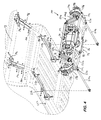
- FIG. 1 is a rear perspective view of an independent rear suspension kit of the invention.
- FIG. 2 is a front perspective view of the independent rear suspension kit of FIG. 1 .
- FIG. 3 is an exploded, rear perspective view of the independent rear suspension kit of FIG. 1 .
- FIG. 4 is a bottom perspective view of the independent rear suspension kit of FIG. 1 assembled to a vehicle chassis.
- FIGS. 1 and 2 illustrate an independent rear suspension kit 10 for a vehicle originally equipped with a solid-axle suspension system.
- the kit 10 may be used for converting the vehicle from a solid-axle suspension system to an independent rear suspension system.
- the kit 10 may be used as original equipment in a specialty vehicle (e.g., a tube-frame race car) to provide an independent rear suspension system.
- the kit 10 includes first (i.e., driver-side) and second (i.e., passenger-side) mounting brackets 14 a , 14 b configured to be fastened to a chassis 18 of the vehicle ( FIG. 4 ).
- the vehicle includes a rear sub-frame 22 to which the brackets 14 a , 14 b are attached.
- each of the brackets 14 a , 14 b is shaped to follow the contour of parallel rails 26 a , 26 b of the rear sub-frame 22 .
- the shape of the brackets 14 a , 14 b dictates the placement or location of the brackets 14 a , 14 b on the respective rails 26 a , 26 b .
- the brackets 14 a , 14 b are fastened to the rails 26 a , 26 b using conventional threaded fasteners to clamp the brackets 14 a , 14 b to the respective rails 26 a , 26 b .
- brackets 14 a , 14 b may be welded to the rails 26 a , 26 b of the rear sub-frame 22 .
- the illustrated kit 10 in FIGS. 1 and 2 is specially configured for use with a Chevrolet Camaro, model years 1967-1969. The shapes of some of the components, however, may be modified to adapt the kit 10 for use with different vehicles.
- the kit 10 also includes a cross-member 30 interconnecting the first and second brackets 14 a , 14 b .
- each of the brackets 14 a , 14 b includes a mount 34 a , 34 b ( FIG. 4 ), and opposed ends of the cross-member 30 are fastened to the respective mounts 34 a , 34 b to secure the cross-member 30 to the rear sub-frame 22 of the vehicle's chassis 18 .
- a rubber or polymeric cylindrical bushing 38 is received in each end of the cross-member 30 to interconnect the ends of the cross-member 30 with the respective mounts 34 a , 34 b on the brackets 14 a , 14 b to attenuate vibration transferred to the vehicle's chassis 18 .
- Conventional threaded fasteners are received in the bushings 38 and are utilized to connect the opposed ends of the cross-member 30 with the respective mounts 34 a , 34 b.
- the kit 10 further includes a differential housing 42 supported by the cross-member 30 .
- the differential housing 42 includes spaced flanges 46 a , 46 b ( FIG. 3 ) having a plurality of threaded holes 50 .
- a corresponding plurality of threaded fasteners are inserted through respective apertures 54 in the cross-member 30 and received in the threaded holes 50 to support the differential housing 42 from the cross-member 30 .
- the differential housing 42 also includes two arms 58 a , 58 b , the purpose of which is described in detail below, extending from the bottom of the differential housing 42 .
- the arms 58 a , 58 b are welded to the differential housing 42 ; however, in an alternative embodiment of the kit 10 the differential housing 42 and the arms 58 a , 58 b may be integrally formed as a single piece (e.g., by machining from a billet, by casting, etc.).
- a “third member” or a differential unit 62 is attached to the differential housing 42 in a conventional manner.
- the differential unit 62 includes a case 66 and a differential (not shown) at least partially received within the case 66 .
- the differential unit 62 includes an input yoke (not shown) to receive torque from the vehicle's engine (e.g., via a drive shaft, also not shown).
- the kit 10 also includes a saddle 78 having opposed first and second ends interconnecting the first and second brackets 14 a , 14 b , respectively.
- the saddle 78 includes end plates 82 that are fastened to the respective brackets 14 a , 14 b .
- the saddle 78 also includes a middle portion 86 coupled to the differential housing 42 to further secure the differential housing 42 to the rear sub-frame 22 of the vehicle's chassis 18 .
- the saddle 78 includes a V-shaped tube 90 and the middle portion 86 of the saddle 78 includes opposed, parallel plates 94 , 98 at least one of which is welded to the tube 90 .
- the plate 94 also includes a flange 102 that is fastened to the case 66 of the differential unit 62 which, in turn, is fastened to the differential housing 42 .
- the kit 10 further includes first and second upper control arms 106 a , 106 b pivotably coupled to the cross-member 30 .
- Each of the first and second upper control arms 106 a , 106 b includes opposed ends to which threaded spherical rod ends 110 , 114 are attached ( FIG. 3 ).
- the inboard rod end 110 on each of the upper control arms 106 a , 106 b is pivotably coupled to the cross-member 30 via an upper control arm mount 118 a , 118 b and a conventional threaded fastener.
- the upper control arms 106 a , 106 b are shaped with a curvature to provide clearance for the mounting brackets 14 a , 14 b and the rails 26 a , 26 b of the rear sub-frame 22 .
- the upper control arms 106 a , 106 b may be substantially straight.
- the length of each of the upper control arms 106 a , 106 b is adjustable to adjust a camber angle of the respective rear wheels.
- the upper control arms 106 a , 106 b may be independently lengthened or shortened by adjusting the depth to which the spherical rod ends 110 , 114 are threaded into the respective ends of the control arms 106 a , 106 b.
- the kit 10 also includes first and second lower control arms 122 a , 122 b pivotably coupled to the differential housing 42 and the saddle 78 .
- Each of the lower control arms 122 a , 122 b is generally A-shaped and includes a forward tube 126 and a rearward tube 130 that taper toward each other.
- each of the lower control arms 122 a , 122 b is pivotably coupled to the saddle 78 (i.e., via the plates 94 , 98 ) using a conventional threaded fastener, while the rearward tube 130 of each of the lower control arms 122 a , 122 b is pivotably coupled to the respective arms 58 a , 58 b of the differential housing 42 using a conventional threaded fastener.
- the lower control arms 122 a , 122 b also include tie rod end bushings 124 pivotably coupling the lower control arms 122 a , 122 b to the differential housing 42 and the saddle 78 .
- the bushings 124 are rotatable with respect to the remainder of the lower control arms 122 a , 122 b to adjust the overall length of the lower control arms 122 a , 122 b . Accordingly, the tie rod end bushings 124 may be adjusted to vary the track width or the toe of the vehicle in which the kit 10 is installed.
- the tie rod end bushings 124 may include rubber or polymeric bushings to attenuate vibration transferred to the differential housing 42 and the vehicle's chassis 18 .
- the kit 10 further includes a tie link 134 interconnecting the first and second arms 58 a , 58 b of the differential housing 42 to increase the rigidity of the arms 58 a , 58 b .
- the tie link 134 is welded to the differential housing 42 and defines at least a portion of each of the arms 58 a , 58 b.
- the kit 10 further includes a first upright 138 a pivotably coupled to the first upper control arm 106 a and the first lower control arm 122 a , and a second upright 138 b pivotably coupled to the second upper control arm 106 b and the second lower control arm 122 b .
- the first and second uprights 138 a , 138 b each include a lower pivot mount 142 positioned between the respective tubes 126 , 130 of each of the lower control arms 122 a , 122 b .
- a single threaded fastener is inserted through the lower pivot mount 142 to interconnect the respective tubes 126 , 130 of each of the lower control arms 122 a , 122 b to pivotably couple the uprights 138 a , 138 b to the respective lower control arms 122 a , 122 b .
- Each of the uprights 138 a , 138 b also includes an upper pivot mount 146 to which the outboard rod ends 114 of the respective upper control arms 106 a , 106 b are pivotably coupled using conventional threaded fasteners.
- the length of the upper control arms 106 a , 106 b is adjustable to permit adjustment of the camber angle of each of the uprights 138 a , 138 b , and therefore the rear wheels.
- the kit 10 also includes a first suspension member 150 a interconnecting the cross-member 30 and the first lower control arm 122 a , and a second suspension member 150 b interconnecting the cross-member 30 and the second lower control arm 122 b .
- the first and second suspension members 150 a , 150 b are each configured as coil-over shocks 154 having an adjustable shock 158 surrounded by a coil spring 162 .
- both the preload on the coil spring 162 and the damping coefficient of the shock 158 are independently adjustable to change the performance of the coil-over shocks 154 .
- each of the coil-over shocks 154 is pivotably coupled to a respective upper shock mount 166 a , 166 b attached to the cross-member 30 (see also FIG. 4 ).
- a conventional threaded fastener is utilized to pivotably couple each of the coil-over shocks 154 with the respective upper shock mounts 166 a , 166 b on the cross-member 30 .
- the lower control arms 122 a , 122 b include respective lower shock mounts 170 a , 170 b attached to the rearward tube 130 of each of the lower control arms 122 a , 122 b .
- a conventional threaded fastener is utilized to pivotably couple the lower end of each of the coil-over shocks 154 with the respective lower shock mounts 170 a , 170 b on the lower control arms 122 a , 122 b .
- the vertical forces acting on the rear wheels while the vehicle is in operation are transferred to the vehicle's chassis 18 through the uprights 138 a , 138 b , the lower control arms 122 a , 122 b , the coil-over shocks 154 , the cross-member 30 , and the brackets 14 a , 14 b.
- the kit 10 further includes a first stub axle assembly 174 a extending between the first upright 138 a and the differential housing 42 , and a second stub axle assembly 174 b extending between the second upright 138 b and the differential housing 42 .
- the inboard ends of the respective stub axle assemblies 174 a , 174 b are coupled to the differential to receive torque from the differential when the vehicle is in operation, while the outboard ends of the respective stub axle assemblies 174 a , 174 b are coupled to respective hubs 178 a , 178 b that are rotatably supported by the uprights 138 a , 138 b .
- the hubs 178 a , 178 b each include a plurality of axle studs (not shown) for securing the rear wheels to the hubs 178 a , 178 b (e.g., using lug nuts). As such, torque from the differential is transferred to the respective rear wheels of the vehicle through the respective stub axle assemblies 174 a , 174 b and the hubs 178 a , 178 b.
- the first and second stub axle assemblies 174 a , 174 b each include a stub axle 186 rotatably supported by the differential housing 42 and engaged with the differential.
- the first and second stub axle assemblies 174 a , 174 b also each include an axle shaft 190 having a first end and a second end, a first constant-velocity joint 194 coupling the stub axle 186 with the first end of the axle shaft 190 , an output shaft (not shown) coupled for co-rotation with the hub 178 a , 178 b , and a second constant-velocity joint 198 coupling the second end of the axle shaft 190 with the output shaft.
- torque is transferred from the differential through the stub axle 186 , the first constant-velocity joint 194 , the axle shaft 190 , the second constant-velocity joint 198 , and the output shaft of the respective assemblies 174 a , 174 b before reaching the hubs 178 a , 178 b and the respective rear wheels of the vehicle.
- the kit 10 also includes a first rotor 202 a coupled for co-rotation with the first stub-axle assembly 174 a and a second rotor 202 b coupled for co-rotation with the second stub-axle assembly 174 b .
- the rotors 202 a , 202 b are positioned between the stub axle 186 and the first constant-velocity joint 194 in each of the stub axle assemblies 174 a , 174 b .
- the rotors 202 a , 202 b are located inboard of the respective uprights 138 a , 138 b such that the rotors 202 a , 202 b do not contribute to the sprung mass of the kit 10 .
- the rotors 202 a , 202 b are not moved upwardly and downwardly with the rear wheels and uprights 138 a , 138 b when the vehicle is in operation.
- Conventional threaded fasteners are used to secure the first rotor 202 a between the first constant-velocity joint 194 and the stub axle 186 of the first stub axle assembly 174 a .
- conventional threaded fasteners are used to secure the second rotor 202 b between the first constant-velocity joint 194 and the stub axle 186 of the second stub axle assembly 174 b.
- the kit 10 further includes first and second calipers 206 a , 206 b mounted to the differential housing 42 which, when actuated, apply a braking force on the first and second rotors 202 a , 202 b to decelerate the rotation of the stub axle assemblies 174 a , 174 b to bring the vehicle to a stop.
- Respective caliper mounts 210 a , 210 b are fastened to the differential housing 42 to which the first and second calipers 206 a , 206 b are fastened ( FIG. 3 ).
- the kit 10 also includes a first strut rod 214 a configured to interconnect the first lower control arm 122 a and the chassis 18 , and a second strut rod 214 b configured to interconnect the second lower control arm 122 b and the chassis 18 .
- Both of the strut rods 214 a , 214 b extend toward the front of the vehicle's chassis 18 ( FIG. 4 ) and are operable to transfer the propulsion forces resulting from the contact between the vehicle's rear wheels and the driving surface to the vehicle's chassis 18 .
- the strut rods 214 a , 214 b extend in a direction substantially parallel to the length of the vehicle.
- the strut rods 214 a , 214 b may be obliquely oriented with respect to a central axis of the chassis 18 .
- the kit 10 further includes first and second sub-frame connectors 218 a , 218 b configured to interconnect a front sub-frame 222 and the rear sub-frame 22 of the vehicle's chassis 18 .
- the first strut rod 214 a includes opposed ends pivotably coupled to the first sub-frame connector 218 a and the first lower control arm 122 a , respectively.
- the second strut rod 214 b includes opposed ends pivotably coupled to the second sub-frame connector 218 b and the second lower control arm 122 b , respectively.
- the sub-frame connectors 218 a , 218 b each include an offset strut mount 226 to which the respective strut rods 214 a , 214 b are pivotably coupled.
- the lower control arms 122 a , 122 b also each include a strut mount 230 to which the respective strut rods 214 a , 214 b are pivotably coupled.
- the vehicle's rear wheels are substantially isolated from each other such that an input to the suspension system by one of the wheels (e.g., a jouncing motion) does not affect the other of the wheels. Consequently, the handling characteristics of the vehicle may be improved by using the kit 10 in place of the solid-axle suspension system originally equipped in the vehicle.
Landscapes
- Engineering & Computer Science (AREA)
- Mechanical Engineering (AREA)
- Vehicle Body Suspensions (AREA)
Abstract
An independent rear suspension kit includes first and second mounting brackets configured to be fastened to a chassis of a vehicle, a cross-member interconnecting the first and second brackets, a differential housing supported by the cross-member, first and second upper control arms pivotably coupled to the cross-member, first and second lower control arms pivotably coupled to the differential housing, a first upright pivotably coupled to the first upper control arm and the first lower control arm, and a second upright pivotably coupled to the second upper control arm and the second lower control arm.
Description
This application claims priority to U.S. Provisional Patent Application No. 61/480,196 filed on Apr. 28, 2011, the entire content of which is incorporated herein by reference.
The present invention relates to vehicles, and more particularly to vehicle suspension systems.
Rear-wheel drive passenger vehicles are typically designed with a solid-axle suspension system for transferring an engine's torque to the rear wheels of the vehicle. Such solid-axle suspension systems typically include an axle housing, a differential located in the axle housing, and two axles interconnecting the differential and the respective rear wheels of the vehicle. The axle housing is typically supported relative to the vehicle's chassis by multiple springs to permit the axle housing to move upwardly and downwardly relative to the vehicle's chassis as the vehicle is moving in response to irregularities in the driving surface.
Solid-axle suspension systems, however, inherently compromise a vehicle's performance or handling to some extent because a solid-axle suspension system is responsive to inputs received from either of the rear wheels of the vehicle. For example, should the driver-side rear wheel encounter an irregularity in a driving surface (e.g., a pothole), the driver-side rear wheel would be caused to move downwardly relative to the vehicle's chassis, and the passenger-side rear wheel may be caused to move upwardly or tilt inwardly, thereby losing camber, in response to the input provided on the driver-side rear wheel.
The invention provides an independent rear suspension kit for a vehicle originally equipped with a solid-axle suspension system to increase the performance and handling of the vehicle. Independent rear suspension systems, as described in more detail below, substantially isolate a vehicle's rear wheels such that an input to the system by one of the wheels does not affect the other of the wheels.
The invention provides, in one aspect, an independent rear suspension kit for a vehicle. The kit includes first and second mounting brackets configured to be fastened to a chassis of the vehicle, a cross-member interconnecting the first and second brackets, a differential housing supported by the cross-member, first and second upper control arms pivotably coupled to the cross-member, first and second lower control arms pivotably coupled to the differential housing, a first upright pivotably coupled to the first upper control arm and the first lower control arm, and a second upright pivotably coupled to the second upper control arm and the second lower control arm.
Other features and aspects of the invention will become apparent by consideration of the following detailed description and accompanying drawings.
Before any embodiments of the invention are explained in detail, it is to be understood that the invention is not limited in its application to the details of construction and the arrangement of components set forth in the following description or illustrated in the following drawings. The invention is capable of other embodiments and of being practiced or of being carried out in various ways. Also, it is to be understood that the phraseology and terminology used herein is for the purpose of description and should not be regarded as limiting.
With reference to FIGS. 1-3 , the kit 10 also includes a cross-member 30 interconnecting the first and second brackets 14 a, 14 b. Particularly, each of the brackets 14 a, 14 b includes a mount 34 a, 34 b (FIG. 4 ), and opposed ends of the cross-member 30 are fastened to the respective mounts 34 a, 34 b to secure the cross-member 30 to the rear sub-frame 22 of the vehicle's chassis 18. A rubber or polymeric cylindrical bushing 38 is received in each end of the cross-member 30 to interconnect the ends of the cross-member 30 with the respective mounts 34 a, 34 b on the brackets 14 a, 14 b to attenuate vibration transferred to the vehicle's chassis 18. Conventional threaded fasteners are received in the bushings 38 and are utilized to connect the opposed ends of the cross-member 30 with the respective mounts 34 a, 34 b.
With reference to FIG. 1 , the kit 10 further includes a differential housing 42 supported by the cross-member 30. The differential housing 42 includes spaced flanges 46 a, 46 b (FIG. 3 ) having a plurality of threaded holes 50. A corresponding plurality of threaded fasteners are inserted through respective apertures 54 in the cross-member 30 and received in the threaded holes 50 to support the differential housing 42 from the cross-member 30. The differential housing 42 also includes two arms 58 a, 58 b, the purpose of which is described in detail below, extending from the bottom of the differential housing 42. The arms 58 a, 58 b are welded to the differential housing 42; however, in an alternative embodiment of the kit 10 the differential housing 42 and the arms 58 a, 58 b may be integrally formed as a single piece (e.g., by machining from a billet, by casting, etc.). As shown in FIG. 2 , a “third member” or a differential unit 62 is attached to the differential housing 42 in a conventional manner. The differential unit 62 includes a case 66 and a differential (not shown) at least partially received within the case 66. The differential unit 62 includes an input yoke (not shown) to receive torque from the vehicle's engine (e.g., via a drive shaft, also not shown).
With continued reference to FIG. 2 , the kit 10 also includes a saddle 78 having opposed first and second ends interconnecting the first and second brackets 14 a, 14 b, respectively. Particularly, the saddle 78 includes end plates 82 that are fastened to the respective brackets 14 a, 14 b. The saddle 78 also includes a middle portion 86 coupled to the differential housing 42 to further secure the differential housing 42 to the rear sub-frame 22 of the vehicle's chassis 18. The saddle 78 includes a V-shaped tube 90 and the middle portion 86 of the saddle 78 includes opposed, parallel plates 94, 98 at least one of which is welded to the tube 90. The plate 94 also includes a flange 102 that is fastened to the case 66 of the differential unit 62 which, in turn, is fastened to the differential housing 42.
With reference to FIGS. 1-3 , the kit 10 further includes first and second upper control arms 106 a, 106 b pivotably coupled to the cross-member 30. Each of the first and second upper control arms 106 a, 106 b includes opposed ends to which threaded spherical rod ends 110, 114 are attached (FIG. 3 ). The inboard rod end 110 on each of the upper control arms 106 a, 106 b is pivotably coupled to the cross-member 30 via an upper control arm mount 118 a, 118 b and a conventional threaded fastener. In the illustrated construction of the kit 10, the upper control arms 106 a, 106 b are shaped with a curvature to provide clearance for the mounting brackets 14 a, 14 b and the rails 26 a, 26 b of the rear sub-frame 22. Alternatively, in a vehicle configuration in which no clearance issues are posed by the mounting brackets 14 a, 14 b or the rear sub-frame 22, the upper control arms 106 a, 106 b may be substantially straight. The length of each of the upper control arms 106 a, 106 b is adjustable to adjust a camber angle of the respective rear wheels. Particularly, the upper control arms 106 a, 106 b may be independently lengthened or shortened by adjusting the depth to which the spherical rod ends 110, 114 are threaded into the respective ends of the control arms 106 a, 106 b.
With reference to FIGS. 1-3 , the kit 10 also includes first and second lower control arms 122 a, 122 b pivotably coupled to the differential housing 42 and the saddle 78. Each of the lower control arms 122 a, 122 b is generally A-shaped and includes a forward tube 126 and a rearward tube 130 that taper toward each other. The forward tube 126 of each of the lower control arms 122 a, 122 b is pivotably coupled to the saddle 78 (i.e., via the plates 94, 98) using a conventional threaded fastener, while the rearward tube 130 of each of the lower control arms 122 a, 122 b is pivotably coupled to the respective arms 58 a, 58 b of the differential housing 42 using a conventional threaded fastener. The lower control arms 122 a, 122 b also include tie rod end bushings 124 pivotably coupling the lower control arms 122 a, 122 b to the differential housing 42 and the saddle 78. The bushings 124 are rotatable with respect to the remainder of the lower control arms 122 a, 122 b to adjust the overall length of the lower control arms 122 a, 122 b. Accordingly, the tie rod end bushings 124 may be adjusted to vary the track width or the toe of the vehicle in which the kit 10 is installed. The tie rod end bushings 124 may include rubber or polymeric bushings to attenuate vibration transferred to the differential housing 42 and the vehicle's chassis 18. With reference to FIG. 1 , the kit 10 further includes a tie link 134 interconnecting the first and second arms 58 a, 58 b of the differential housing 42 to increase the rigidity of the arms 58 a, 58 b. In the illustrated embodiment of the kit 10, the tie link 134 is welded to the differential housing 42 and defines at least a portion of each of the arms 58 a, 58 b.
With reference to FIGS. 1-3 , the kit 10 further includes a first upright 138 a pivotably coupled to the first upper control arm 106 a and the first lower control arm 122 a, and a second upright 138 b pivotably coupled to the second upper control arm 106 b and the second lower control arm 122 b. As shown in FIG. 3 , the first and second uprights 138 a, 138 b each include a lower pivot mount 142 positioned between the respective tubes 126, 130 of each of the lower control arms 122 a, 122 b. A single threaded fastener is inserted through the lower pivot mount 142 to interconnect the respective tubes 126, 130 of each of the lower control arms 122 a, 122 b to pivotably couple the uprights 138 a, 138 b to the respective lower control arms 122 a, 122 b. Each of the uprights 138 a, 138 b also includes an upper pivot mount 146 to which the outboard rod ends 114 of the respective upper control arms 106 a, 106 b are pivotably coupled using conventional threaded fasteners. As described above, the length of the upper control arms 106 a, 106 b is adjustable to permit adjustment of the camber angle of each of the uprights 138 a, 138 b, and therefore the rear wheels.
With reference to FIGS. 1 and 3 , the kit 10 also includes a first suspension member 150 a interconnecting the cross-member 30 and the first lower control arm 122 a, and a second suspension member 150 b interconnecting the cross-member 30 and the second lower control arm 122 b. In the illustrated construction of the kit 10, the first and second suspension members 150 a, 150 b are each configured as coil-over shocks 154 having an adjustable shock 158 surrounded by a coil spring 162. As would be understood by one of ordinary skill in the art, both the preload on the coil spring 162 and the damping coefficient of the shock 158 are independently adjustable to change the performance of the coil-over shocks 154. An upper end of each of the coil-over shocks 154 is pivotably coupled to a respective upper shock mount 166 a, 166 b attached to the cross-member 30 (see also FIG. 4 ). A conventional threaded fastener is utilized to pivotably couple each of the coil-over shocks 154 with the respective upper shock mounts 166 a, 166 b on the cross-member 30. With reference to FIGS. 1 and 3 , the lower control arms 122 a, 122 b include respective lower shock mounts 170 a, 170 b attached to the rearward tube 130 of each of the lower control arms 122 a, 122 b. Like the upper shock mounts 166 a, 166 b, a conventional threaded fastener is utilized to pivotably couple the lower end of each of the coil-over shocks 154 with the respective lower shock mounts 170 a, 170 b on the lower control arms 122 a, 122 b. As such, the vertical forces acting on the rear wheels while the vehicle is in operation are transferred to the vehicle's chassis 18 through the uprights 138 a, 138 b, the lower control arms 122 a, 122 b, the coil-over shocks 154, the cross-member 30, and the brackets 14 a, 14 b.
With continued reference to FIGS. 1 and 3 , the kit 10 further includes a first stub axle assembly 174 a extending between the first upright 138 a and the differential housing 42, and a second stub axle assembly 174 b extending between the second upright 138 b and the differential housing 42. The inboard ends of the respective stub axle assemblies 174 a, 174 b are coupled to the differential to receive torque from the differential when the vehicle is in operation, while the outboard ends of the respective stub axle assemblies 174 a, 174 b are coupled to respective hubs 178 a, 178 b that are rotatably supported by the uprights 138 a, 138 b. The hubs 178 a, 178 b each include a plurality of axle studs (not shown) for securing the rear wheels to the hubs 178 a, 178 b (e.g., using lug nuts). As such, torque from the differential is transferred to the respective rear wheels of the vehicle through the respective stub axle assemblies 174 a, 174 b and the hubs 178 a, 178 b.
With reference to FIG. 3 , the first and second stub axle assemblies 174 a, 174 b each include a stub axle 186 rotatably supported by the differential housing 42 and engaged with the differential. The first and second stub axle assemblies 174 a, 174 b also each include an axle shaft 190 having a first end and a second end, a first constant-velocity joint 194 coupling the stub axle 186 with the first end of the axle shaft 190, an output shaft (not shown) coupled for co-rotation with the hub 178 a, 178 b, and a second constant-velocity joint 198 coupling the second end of the axle shaft 190 with the output shaft. As such, torque is transferred from the differential through the stub axle 186, the first constant-velocity joint 194, the axle shaft 190, the second constant-velocity joint 198, and the output shaft of the respective assemblies 174 a, 174 b before reaching the hubs 178 a, 178 b and the respective rear wheels of the vehicle.
With reference to FIGS. 1-3 , the kit 10 also includes a first rotor 202 a coupled for co-rotation with the first stub-axle assembly 174 a and a second rotor 202 b coupled for co-rotation with the second stub-axle assembly 174 b. The rotors 202 a, 202 b are positioned between the stub axle 186 and the first constant-velocity joint 194 in each of the stub axle assemblies 174 a, 174 b. Therefore, the rotors 202 a, 202 b are located inboard of the respective uprights 138 a, 138 b such that the rotors 202 a, 202 b do not contribute to the sprung mass of the kit 10. In other words, the rotors 202 a, 202 b are not moved upwardly and downwardly with the rear wheels and uprights 138 a, 138 b when the vehicle is in operation. Conventional threaded fasteners are used to secure the first rotor 202 a between the first constant-velocity joint 194 and the stub axle 186 of the first stub axle assembly 174 a. Likewise, conventional threaded fasteners are used to secure the second rotor 202 b between the first constant-velocity joint 194 and the stub axle 186 of the second stub axle assembly 174 b.
With reference to FIGS. 1 and 3 , the kit 10 further includes first and second calipers 206 a, 206 b mounted to the differential housing 42 which, when actuated, apply a braking force on the first and second rotors 202 a, 202 b to decelerate the rotation of the stub axle assemblies 174 a, 174 b to bring the vehicle to a stop. Respective caliper mounts 210 a, 210 b are fastened to the differential housing 42 to which the first and second calipers 206 a, 206 b are fastened (FIG. 3 ).
With reference to FIG. 2 , the kit 10 also includes a first strut rod 214 a configured to interconnect the first lower control arm 122 a and the chassis 18, and a second strut rod 214 b configured to interconnect the second lower control arm 122 b and the chassis 18. Both of the strut rods 214 a, 214 b extend toward the front of the vehicle's chassis 18 (FIG. 4 ) and are operable to transfer the propulsion forces resulting from the contact between the vehicle's rear wheels and the driving surface to the vehicle's chassis 18. In the illustrated embodiment of the kit 10, the strut rods 214 a, 214 b extend in a direction substantially parallel to the length of the vehicle. Alternatively, depending upon the particular configuration of the vehicle's chassis 18, the strut rods 214 a, 214 b may be obliquely oriented with respect to a central axis of the chassis 18.
With continued reference to FIG. 4 , the kit 10 further includes first and second sub-frame connectors 218 a, 218 b configured to interconnect a front sub-frame 222 and the rear sub-frame 22 of the vehicle's chassis 18. The first strut rod 214 a includes opposed ends pivotably coupled to the first sub-frame connector 218 a and the first lower control arm 122 a, respectively. Likewise, the second strut rod 214 b includes opposed ends pivotably coupled to the second sub-frame connector 218 b and the second lower control arm 122 b, respectively. The sub-frame connectors 218 a, 218 b each include an offset strut mount 226 to which the respective strut rods 214 a, 214 b are pivotably coupled. The lower control arms 122 a, 122 b also each include a strut mount 230 to which the respective strut rods 214 a, 214 b are pivotably coupled.
In operation of a vehicle using the independent rear suspension kit 10 described above, the vehicle's rear wheels are substantially isolated from each other such that an input to the suspension system by one of the wheels (e.g., a jouncing motion) does not affect the other of the wheels. Consequently, the handling characteristics of the vehicle may be improved by using the kit 10 in place of the solid-axle suspension system originally equipped in the vehicle.
Various features of the invention are set forth in the following claims.
Claims (20)
1. An independent rear suspension kit for a vehicle, the kit comprising:
first and second mounting brackets configured to be fastened to a chassis of the vehicle;
a cross-member separate from and interconnecting the first and second brackets;
a differential housing secured to the cross-member, the differential housing having first and second arms extending therefrom;
first and second upper control arms pivotably coupled to the cross-member;
first and second lower control arms pivotably coupled to the first and second arms, respectively, of the differential housing;
a first upright pivotably coupled to the first upper control arm and the first lower control arm; and
a second upright pivotably coupled to the second upper control arm and the second lower control arm.
2. The independent rear suspension kit of claim 1 , further comprising:
a first suspension member interconnecting the cross-member and the first lower control arm; and
a second suspension member interconnecting the cross-member and the second lower control arm.
3. The independent rear suspension kit of claim 2 , wherein the first and second suspension members are each configured as coil-over shocks.
4. The independent rear suspension kit of claim 1 , further comprising:
a first stub axle assembly extending between the first upright and the differential housing; and
a second stub axle assembly extending between the second upright and the differential housing.
5. The independent rear suspension kit of claim 4 , further comprising:
a first rotor coupled for co-rotation with the first stub-axle assembly;
a first caliper mounted to the differential housing and configured to apply a braking force on the first rotor;
a second rotor coupled for co-rotation with the second stub-axle assembly; and
a second caliper mounted to the differential housing and configured to apply a braking force on the second rotor.
6. The independent rear suspension kit of claim 5 , further comprising:
a first caliper mount fastened to the differential housing to which the first caliper is fastened; and
a second caliper mount fastened to the differential housing to which the second caliper is fastened.
7. The independent rear suspension kit of claim 5 , wherein the first rotor is coupled to the first stub-axle assembly inboard of the first upright, and wherein the second rotor is coupled to the second stub-axle assembly inboard of the second upright.
8. The independent rear suspension kit of claim 4 , wherein the first and second stub axle assemblies each include
a stub axle having a first end and a second end;
a first constant-velocity joint coupled to the first end of the stub axle; and
a second constant-velocity joint coupled to the second end of the stub axle.
9. The independent rear suspension kit of claim 8 , wherein the first constant-velocity joint of each of the first and second stub axle assemblies are configured to interconnect with a differential at least partially received within the differential housing to receive torque from the differential, and wherein the rear suspension kit further includes
a first hub rotatably supported by the first upright and interconnected with the second constant-velocity joint of the first stub axle assembly to receive torque from the second constant-velocity joint of the first stub axle assembly, and
a second hub rotatably supported by the second upright and interconnected with the second constant-velocity joint of the second stub axle assembly to receive torque from the second constant-velocity joint of the second stub axle assembly.
10. The independent rear suspension kit of claim 1 , further comprising a saddle separate from the cross-member and including opposed first and second ends interconnecting the first and second brackets, respectively, and a middle portion coupled to the differential housing.
11. The independent rear suspension kit of claim 10 , wherein the first and second lower control arms are each pivotably coupled to the middle portion of the saddle.
12. The independent rear suspension kit of claim 1 , further comprising:
a first strut rod configured to interconnect the first lower control arm and the chassis and extending toward the front of the chassis; and
a second strut rod configured to interconnect the second lower control arm and the chassis and extending toward the front of the chassis.
13. The independent rear suspension kit of claim 12 , further comprising:
a first sub-frame connector configured to interconnect at least a first sub-frame and a second sub-frame of the chassis; and
a second sub-frame connector configured to interconnect the first sub-frame and the second sub-frame.
14. The independent rear suspension kit of claim 13 , wherein the first strut rod includes opposed ends pivotably coupled to the first sub-frame connector and the first lower control arm, respectively, and wherein the second strut rod includes opposed ends pivotably coupled to the second sub-frame connector and the second lower control arm, respectively.
15. The independent rear suspension kit of claim 1 , wherein the first and second arms are integrally formed with the differential housing as a single piece.
16. The independent rear suspension kit of claim 1 , further comprising a tie link interconnecting the first and second arms.
17. The independent rear suspension kit of claim 1 , wherein the differential housing includes a plurality of threaded holes, and wherein a corresponding plurality of threaded fasteners are received in the threaded holes to support the differential housing from the cross-member.
18. The independent rear suspension kit of claim 1 , wherein the length of each of the first and second upper control arms is adjustable to adjust a camber angle of the first and second uprights, respectively.
19. The independent rear suspension kit of claim 1 , wherein each of the first and second brackets includes a mount, and wherein opposed ends of the cross-member are fastened to the respective mounts of the first and second brackets.
20. The independent rear suspension kit of claim 1 , wherein each of the first and second lower control arms includes an adjustable length for adjusting track width and toe of the vehicle.
Priority Applications (1)
| Application Number | Priority Date | Filing Date | Title |
|---|---|---|---|
| US13/458,187 US8517140B2 (en) | 2011-04-28 | 2012-04-27 | Independent rear suspension kit |
Applications Claiming Priority (2)
| Application Number | Priority Date | Filing Date | Title |
|---|---|---|---|
| US201161480196P | 2011-04-28 | 2011-04-28 | |
| US13/458,187 US8517140B2 (en) | 2011-04-28 | 2012-04-27 | Independent rear suspension kit |
Publications (2)
| Publication Number | Publication Date |
|---|---|
| US20120326410A1 US20120326410A1 (en) | 2012-12-27 |
| US8517140B2 true US8517140B2 (en) | 2013-08-27 |
Family
ID=47361139
Family Applications (1)
| Application Number | Title | Priority Date | Filing Date |
|---|---|---|---|
| US13/458,187 Active US8517140B2 (en) | 2011-04-28 | 2012-04-27 | Independent rear suspension kit |
Country Status (1)
| Country | Link |
|---|---|
| US (1) | US8517140B2 (en) |
Cited By (20)
| Publication number | Priority date | Publication date | Assignee | Title |
|---|---|---|---|---|
| US20130127146A1 (en) * | 2010-03-29 | 2013-05-23 | Mazda Motor Corporation | Support mount bracket, method for mounting front differential gear unit, and attachment structure of front differential gear unit |
| US20130291509A1 (en) * | 2012-05-07 | 2013-11-07 | Briggs And Stratton Corporation | Suspension system and method |
| US20140367951A1 (en) * | 2013-06-12 | 2014-12-18 | Arvinmeritor Technology, Llc | Suspension Module Having a Skidplate |
| US20150251510A1 (en) * | 2011-11-14 | 2015-09-10 | Gordon Murray Design Limited | Vehicle suspension |
| US20150283889A1 (en) * | 2014-04-07 | 2015-10-08 | Squaw-Fleet, LLC | Rear carriage structure for an electric vehicle |
| US9707842B2 (en) * | 2012-05-07 | 2017-07-18 | Briggs & Stratton Corporation | Zero-turn radius lawnmower with suspension system |
| USD814979S1 (en) * | 2016-06-06 | 2018-04-10 | Axletech International Ip Holdings, Llc | Suspension axle |
| USD821930S1 (en) * | 2016-06-06 | 2018-07-03 | Axletech International Ip Holdings, Llc | Gearbox assembly for an axle |
| USD823735S1 (en) * | 2016-07-14 | 2018-07-24 | Aircraft Gear Corporation | Constant velocity joint |
| US10189351B2 (en) * | 2015-12-31 | 2019-01-29 | Byd Company Limited | Agitator truck |
| US20190248405A1 (en) * | 2018-02-13 | 2019-08-15 | Polaris Industries Inc. | All-terrain vehicle |
| USD866683S1 (en) * | 2017-10-27 | 2019-11-12 | Traxxas Lp | Rear axle assembly for a model vehicle |
| US10518627B2 (en) * | 2018-06-05 | 2019-12-31 | Ford Global Technologies, Llc | Electric machine integrated axle assemblies for electrified vehicles |
| US10624261B2 (en) | 2017-01-04 | 2020-04-21 | Briggs & Stratton Corporation | Mower suspension system and method |
| US10645874B2 (en) | 2017-01-04 | 2020-05-12 | Briggs & Stratton Corporation | Outdoor power equipment suspension system |
| US20200406682A1 (en) * | 2018-03-09 | 2020-12-31 | Toyota Jidosha Kabushiki Kaisha | Axle structure |
| US11214136B2 (en) * | 2017-07-28 | 2022-01-04 | Dana Heavy Vehicle Systems Group, Llc | Cradle assembly for an electric axle assembly |
| US11247556B2 (en) | 2015-12-17 | 2022-02-15 | Allison Transmission, Inc. | Axle assembly for a vehicle |
| US11267443B2 (en) | 2015-03-11 | 2022-03-08 | Briggs & Stratton, Llc | Machine suspension system |
| US11939017B2 (en) * | 2017-04-03 | 2024-03-26 | Robby Gordon | Off-road front suspension system |
Families Citing this family (10)
| Publication number | Priority date | Publication date | Assignee | Title |
|---|---|---|---|---|
| CN106163848A (en) * | 2014-01-21 | 2016-11-23 | 互动的全电动汽车有限责任公司 | Electric power promotes vehicle |
| JP6014638B2 (en) * | 2014-09-25 | 2016-10-25 | 本田技研工業株式会社 | Swing arm |
| CN107207055B (en) * | 2015-01-21 | 2020-08-18 | 北极星工业有限公司 | Electric vehicle |
| US9701342B2 (en) | 2015-03-31 | 2017-07-11 | Honda Motor Co., Ltd. | Vehicle suspension system, suspension mount assembly and method of mounting a subframe to a frame |
| FR3035028B1 (en) * | 2015-04-16 | 2017-04-21 | Renault Sas | "REVERSE REAR AXLE ASSEMBLY INCORPORATING A SEMI-CARRIER ENGINE FOR A MOTOR VEHICLE" |
| EP3480036A1 (en) * | 2017-11-07 | 2019-05-08 | Volvo Car Corporation | System for wheel suspension of a vehicle |
| EP3495223A1 (en) | 2017-12-11 | 2019-06-12 | Volvo Car Corporation | Driving intervention in vehicles |
| US11161407B2 (en) * | 2018-06-29 | 2021-11-02 | Joseph Coffman | Conversion kit for front differential on a utility vehicle |
| DE102019203836A1 (en) * | 2019-03-20 | 2020-09-24 | Audi Ag | Wheel suspension for a vehicle axle |
| US11807301B2 (en) * | 2020-11-05 | 2023-11-07 | Polaris Industries Inc. | Vehicle |
Citations (14)
| Publication number | Priority date | Publication date | Assignee | Title |
|---|---|---|---|---|
| US3189118A (en) | 1960-12-22 | 1965-06-15 | Ford Motor Co | Vehicle rear wheel suspension |
| US3871467A (en) * | 1972-04-24 | 1975-03-18 | Daimler Benz Ag | Independent wheel suspension for non-steered wheels of motor vehicles |
| US4556238A (en) * | 1983-08-30 | 1985-12-03 | Bayerische Motoren Werke Aktiengesellschaft | Independent wheel suspension for motor vehicles |
| US4717175A (en) * | 1985-11-08 | 1988-01-05 | Toyota Jidosha Kabushiki Kaisha | Steer angle adjusting apparatus for vehicle |
| US5102159A (en) * | 1990-03-29 | 1992-04-07 | Nissan Motor Co., Ltd. | Suspension system for automotive vehicle wheel |
| US6105984A (en) * | 1993-04-14 | 2000-08-22 | Oshkosh Truck Corporation | Independent coil spring suspension for driven wheels |
| US20030111812A1 (en) * | 2001-12-19 | 2003-06-19 | Carlstedt Robert P. | Adjustable suspension assembly control arms |
| US6746032B2 (en) * | 2001-06-20 | 2004-06-08 | Honda Giken Kogyo Kabushiki Kaisha | Suspension structure |
| US6755429B1 (en) * | 2003-05-06 | 2004-06-29 | Ford Global Technologies, Llc | Independent suspension for rear wheels of automotive vehicle |
| US20070235972A1 (en) * | 2006-04-05 | 2007-10-11 | Schmitz Geoffrey W | Modular, central frame, offset, dual control arm independent suspension and suspension retrofit |
| US7661689B2 (en) * | 2006-01-20 | 2010-02-16 | Yamaha Hatsudoki Kabushiki Kaisha | All terrain vehicle |
| US8096567B2 (en) * | 2004-09-23 | 2012-01-17 | Axletech International Ip Holdings, Llc | Independent suspension with adjustable sub-frame |
| US20120031688A1 (en) * | 2010-08-03 | 2012-02-09 | Polaris Industries Inc. | Side-by-side vehicle |
| USD666949S1 (en) * | 2011-04-28 | 2012-09-11 | Heidts Acquisition, Llc | Independent rear suspension kit |
-
2012
- 2012-04-27 US US13/458,187 patent/US8517140B2/en active Active
Patent Citations (14)
| Publication number | Priority date | Publication date | Assignee | Title |
|---|---|---|---|---|
| US3189118A (en) | 1960-12-22 | 1965-06-15 | Ford Motor Co | Vehicle rear wheel suspension |
| US3871467A (en) * | 1972-04-24 | 1975-03-18 | Daimler Benz Ag | Independent wheel suspension for non-steered wheels of motor vehicles |
| US4556238A (en) * | 1983-08-30 | 1985-12-03 | Bayerische Motoren Werke Aktiengesellschaft | Independent wheel suspension for motor vehicles |
| US4717175A (en) * | 1985-11-08 | 1988-01-05 | Toyota Jidosha Kabushiki Kaisha | Steer angle adjusting apparatus for vehicle |
| US5102159A (en) * | 1990-03-29 | 1992-04-07 | Nissan Motor Co., Ltd. | Suspension system for automotive vehicle wheel |
| US6105984A (en) * | 1993-04-14 | 2000-08-22 | Oshkosh Truck Corporation | Independent coil spring suspension for driven wheels |
| US6746032B2 (en) * | 2001-06-20 | 2004-06-08 | Honda Giken Kogyo Kabushiki Kaisha | Suspension structure |
| US20030111812A1 (en) * | 2001-12-19 | 2003-06-19 | Carlstedt Robert P. | Adjustable suspension assembly control arms |
| US6755429B1 (en) * | 2003-05-06 | 2004-06-29 | Ford Global Technologies, Llc | Independent suspension for rear wheels of automotive vehicle |
| US8096567B2 (en) * | 2004-09-23 | 2012-01-17 | Axletech International Ip Holdings, Llc | Independent suspension with adjustable sub-frame |
| US7661689B2 (en) * | 2006-01-20 | 2010-02-16 | Yamaha Hatsudoki Kabushiki Kaisha | All terrain vehicle |
| US20070235972A1 (en) * | 2006-04-05 | 2007-10-11 | Schmitz Geoffrey W | Modular, central frame, offset, dual control arm independent suspension and suspension retrofit |
| US20120031688A1 (en) * | 2010-08-03 | 2012-02-09 | Polaris Industries Inc. | Side-by-side vehicle |
| USD666949S1 (en) * | 2011-04-28 | 2012-09-11 | Heidts Acquisition, Llc | Independent rear suspension kit |
Non-Patent Citations (10)
| Title |
|---|
| CWI Jag IRS Suspension, Concours West Industries, Retrieved from Internet on Oct. 5, 2010 . |
| CWI Jag IRS Suspension, Concours West Industries, Retrieved from Internet on Oct. 5, 2010 <URL: http://www.cwiinc.com/jagsuspensions.htm>. |
| Factory Five Racing Parts Catalog, Independent Rear Suspension, Retrieved from Internet on Oct. 5, 2010 . |
| Factory Five Racing Parts Catalog, Independent Rear Suspension, Retrieved from Internet on Oct. 5, 2010 <URL: http://parts.factoryfive.com/newcatalog/chassis/irs.htm>. |
| How to install Independent Rear Suspension in Musclecars, Hot Rod, Retrieved from Internet on Oct. 5, 2010 <URL: http://www.hotrod.com/howto/hrdp-0712-irs-for-musclecars/bolt-in-kits.html>. |
| How to install Independent Rear Suspension in Musclecars, Hot Rod, Retrieved from Internet on Oct. 5, 2010 <URL: http://www.hotrod.com/howto/hrdp—0712—irs—for—musclecars/bolt—in—kits.html>. |
| Independent Rear Suspensions, Kugel Komponents, Retrieved from Internet on Oct. 28, 2010 . |
| Independent Rear Suspensions, Kugel Komponents, Retrieved from Internet on Oct. 28, 2010 <URL: http://www.kugelkomponents.com/rear—suspension/rearsuspension.php>. |
| Mustang IRS System Product Page, C.T.M. Engineering, Retrieved from Internet on Aug. 25, 2010 . |
| Mustang IRS System Product Page, C.T.M. Engineering, Retrieved from Internet on Aug. 25, 2010 <URL: http://mustangirs.com/products.php>. |
Cited By (40)
| Publication number | Priority date | Publication date | Assignee | Title |
|---|---|---|---|---|
| US8657060B2 (en) * | 2010-03-29 | 2014-02-25 | Ford Global Technologies, Llc | Support mount bracket, method for mounting front differential gear unit, and attachment structure of front differential gear unit |
| US20130127146A1 (en) * | 2010-03-29 | 2013-05-23 | Mazda Motor Corporation | Support mount bracket, method for mounting front differential gear unit, and attachment structure of front differential gear unit |
| US20150251510A1 (en) * | 2011-11-14 | 2015-09-10 | Gordon Murray Design Limited | Vehicle suspension |
| US9469173B2 (en) * | 2011-11-14 | 2016-10-18 | Gordon Murray Design Limited | Vehicle suspension |
| US20170259666A1 (en) * | 2012-05-07 | 2017-09-14 | Briggs And Stratton Corporation | Suspension system and method |
| US20130291509A1 (en) * | 2012-05-07 | 2013-11-07 | Briggs And Stratton Corporation | Suspension system and method |
| US10093179B2 (en) * | 2012-05-07 | 2018-10-09 | Briggs & Stratton Corporation | Zero-turn radius lawnmower with suspension system |
| US10421356B2 (en) * | 2012-05-07 | 2019-09-24 | Briggs & Stratton Corporation | Suspension system and method |
| US11273705B2 (en) | 2012-05-07 | 2022-03-15 | Briggs & Stratton, Llc | Suspension system and method |
| US9597957B2 (en) * | 2012-05-07 | 2017-03-21 | Briggs And Stratton Corporation | Suspension system and method |
| US9707842B2 (en) * | 2012-05-07 | 2017-07-18 | Briggs & Stratton Corporation | Zero-turn radius lawnmower with suspension system |
| US20140367951A1 (en) * | 2013-06-12 | 2014-12-18 | Arvinmeritor Technology, Llc | Suspension Module Having a Skidplate |
| US9221496B2 (en) * | 2013-06-12 | 2015-12-29 | Arvinmeritor Technology, Llc | Suspension module having a skidplate |
| US9573452B2 (en) * | 2014-04-07 | 2017-02-21 | Squaw-Fleet, LLC | Rear carriage structure for an electric vehicle |
| US20150283889A1 (en) * | 2014-04-07 | 2015-10-08 | Squaw-Fleet, LLC | Rear carriage structure for an electric vehicle |
| US11267443B2 (en) | 2015-03-11 | 2022-03-08 | Briggs & Stratton, Llc | Machine suspension system |
| US11858489B2 (en) | 2015-03-11 | 2024-01-02 | Briggs & Stratton, Llc | Machine suspension system |
| US11603078B2 (en) | 2015-03-11 | 2023-03-14 | Briggs & Stratton, Llc | Machine suspension system |
| US11247556B2 (en) | 2015-12-17 | 2022-02-15 | Allison Transmission, Inc. | Axle assembly for a vehicle |
| US11951828B2 (en) | 2015-12-17 | 2024-04-09 | Allison Transmission, Inc. | Axle assembly for a vehicle |
| US10189351B2 (en) * | 2015-12-31 | 2019-01-29 | Byd Company Limited | Agitator truck |
| USD869348S1 (en) * | 2016-06-06 | 2019-12-10 | Allison Transmission, Inc. | Gearbox assembly for an axle |
| USD814979S1 (en) * | 2016-06-06 | 2018-04-10 | Axletech International Ip Holdings, Llc | Suspension axle |
| USD821930S1 (en) * | 2016-06-06 | 2018-07-03 | Axletech International Ip Holdings, Llc | Gearbox assembly for an axle |
| USD823735S1 (en) * | 2016-07-14 | 2018-07-24 | Aircraft Gear Corporation | Constant velocity joint |
| USD878252S1 (en) | 2016-07-14 | 2020-03-17 | Aircraft Gear Corporation | Constant velocity joint |
| US11805729B2 (en) | 2017-01-04 | 2023-11-07 | Briggs & Stratton, Llc | Outdoor power equipment suspension system |
| US10624261B2 (en) | 2017-01-04 | 2020-04-21 | Briggs & Stratton Corporation | Mower suspension system and method |
| US10645874B2 (en) | 2017-01-04 | 2020-05-12 | Briggs & Stratton Corporation | Outdoor power equipment suspension system |
| US10959373B2 (en) | 2017-01-04 | 2021-03-30 | Briggs & Stratton, Llc | Outdoor power equipment suspension system |
| US11939017B2 (en) * | 2017-04-03 | 2024-03-26 | Robby Gordon | Off-road front suspension system |
| US11214136B2 (en) * | 2017-07-28 | 2022-01-04 | Dana Heavy Vehicle Systems Group, Llc | Cradle assembly for an electric axle assembly |
| US11878578B2 (en) | 2017-07-28 | 2024-01-23 | Dana Heavy Vehicle Systems Group, Llc | Cradle assembly for an electric axle assembly |
| USD866683S1 (en) * | 2017-10-27 | 2019-11-12 | Traxxas Lp | Rear axle assembly for a model vehicle |
| US10793181B2 (en) * | 2018-02-13 | 2020-10-06 | Polaris Industries Inc. | All-terrain vehicle |
| US20190248405A1 (en) * | 2018-02-13 | 2019-08-15 | Polaris Industries Inc. | All-terrain vehicle |
| US11840115B2 (en) * | 2018-03-09 | 2023-12-12 | Toyota Jidosha Kabushiki Kaisha | Axle structure |
| US20200406682A1 (en) * | 2018-03-09 | 2020-12-31 | Toyota Jidosha Kabushiki Kaisha | Axle structure |
| US10518627B2 (en) * | 2018-06-05 | 2019-12-31 | Ford Global Technologies, Llc | Electric machine integrated axle assemblies for electrified vehicles |
| US11453288B2 (en) | 2018-06-05 | 2022-09-27 | Ford Global Technologies, Llc | Electric machine integrated axle assemblies for electrified vehicles |
Also Published As
| Publication number | Publication date |
|---|---|
| US20120326410A1 (en) | 2012-12-27 |
Similar Documents
| Publication | Publication Date | Title |
|---|---|---|
| US8517140B2 (en) | Independent rear suspension kit | |
| JP6979501B2 (en) | Vehicle suspension | |
| US6357769B1 (en) | Independent rear suspension system | |
| US7490840B2 (en) | Steering and suspension system for a vehicle | |
| EP2355987B1 (en) | Vehicle independent suspension | |
| EP2403727B1 (en) | Vehicle suspension | |
| US20060208447A1 (en) | Independent suspension for a drive axle | |
| US10118452B2 (en) | Motor vehicle wheel suspension | |
| EP3705321B1 (en) | Suspension system | |
| GB2558771A (en) | Suspension and steering system for a vehicle | |
| US20060033298A1 (en) | Vehicle suspension with improved radius arm to axle attachment | |
| US7618049B2 (en) | Trailing arm suspension | |
| JP2513699B2 (en) | Rear suspension | |
| AU2014328481B2 (en) | Conversion of a two-wheel drive vehicle to a four-wheel drive vehicle | |
| WO2018015942A1 (en) | Vehicle wheel knuckle configuration | |
| EP0083184A2 (en) | Independent rear wheel suspension | |
| OA18478A (en) | Conversion of a two-wheel drive vehicle to a four-wheel drive vehicle. |
Legal Events
| Date | Code | Title | Description |
|---|---|---|---|
| AS | Assignment |
Owner name: HEIDTS ACQUISITION, LLC, ILLINOIS Free format text: ASSIGNMENT OF ASSIGNORS INTEREST;ASSIGNORS:WEST, VAUGHN E.D.;BROWN, THOMAS E.;SIGNING DATES FROM 20120615 TO 20120901;REEL/FRAME:028954/0123 |
|
| STCF | Information on status: patent grant |
Free format text: PATENTED CASE |
|
| FPAY | Fee payment |
Year of fee payment: 4 |
|
| MAFP | Maintenance fee payment |
Free format text: PAYMENT OF MAINTENANCE FEE, 8TH YR, SMALL ENTITY (ORIGINAL EVENT CODE: M2552); ENTITY STATUS OF PATENT OWNER: SMALL ENTITY Year of fee payment: 8 |