US8525974B2 - Omni-directional imaging sensor - Google Patents
Omni-directional imaging sensor Download PDFInfo
- Publication number
- US8525974B2 US8525974B2 US12/932,113 US93211311A US8525974B2 US 8525974 B2 US8525974 B2 US 8525974B2 US 93211311 A US93211311 A US 93211311A US 8525974 B2 US8525974 B2 US 8525974B2
- Authority
- US
- United States
- Prior art keywords
- laser
- signal
- frequency
- laser signal
- angle
- Prior art date
- Legal status (The legal status is an assumption and is not a legal conclusion. Google has not performed a legal analysis and makes no representation as to the accuracy of the status listed.)
- Expired - Fee Related, expires
Links
Images


Classifications
-
- G—PHYSICS
- G01—MEASURING; TESTING
- G01S—RADIO DIRECTION-FINDING; RADIO NAVIGATION; DETERMINING DISTANCE OR VELOCITY BY USE OF RADIO WAVES; LOCATING OR PRESENCE-DETECTING BY USE OF THE REFLECTION OR RERADIATION OF RADIO WAVES; ANALOGOUS ARRANGEMENTS USING OTHER WAVES
- G01S17/00—Systems using the reflection or reradiation of electromagnetic waves other than radio waves, e.g. lidar systems
- G01S17/88—Lidar systems specially adapted for specific applications
- G01S17/89—Lidar systems specially adapted for specific applications for mapping or imaging
-
- G—PHYSICS
- G01—MEASURING; TESTING
- G01S—RADIO DIRECTION-FINDING; RADIO NAVIGATION; DETERMINING DISTANCE OR VELOCITY BY USE OF RADIO WAVES; LOCATING OR PRESENCE-DETECTING BY USE OF THE REFLECTION OR RERADIATION OF RADIO WAVES; ANALOGOUS ARRANGEMENTS USING OTHER WAVES
- G01S17/00—Systems using the reflection or reradiation of electromagnetic waves other than radio waves, e.g. lidar systems
- G01S17/02—Systems using the reflection of electromagnetic waves other than radio waves
- G01S17/06—Systems determining position data of a target
- G01S17/42—Simultaneous measurement of distance and other co-ordinates
-
- G—PHYSICS
- G01—MEASURING; TESTING
- G01S—RADIO DIRECTION-FINDING; RADIO NAVIGATION; DETERMINING DISTANCE OR VELOCITY BY USE OF RADIO WAVES; LOCATING OR PRESENCE-DETECTING BY USE OF THE REFLECTION OR RERADIATION OF RADIO WAVES; ANALOGOUS ARRANGEMENTS USING OTHER WAVES
- G01S17/00—Systems using the reflection or reradiation of electromagnetic waves other than radio waves, e.g. lidar systems
- G01S17/02—Systems using the reflection of electromagnetic waves other than radio waves
- G01S17/50—Systems of measurement based on relative movement of target
- G01S17/58—Velocity or trajectory determination systems; Sense-of-movement determination systems
-
- G—PHYSICS
- G01—MEASURING; TESTING
- G01S—RADIO DIRECTION-FINDING; RADIO NAVIGATION; DETERMINING DISTANCE OR VELOCITY BY USE OF RADIO WAVES; LOCATING OR PRESENCE-DETECTING BY USE OF THE REFLECTION OR RERADIATION OF RADIO WAVES; ANALOGOUS ARRANGEMENTS USING OTHER WAVES
- G01S7/00—Details of systems according to groups G01S13/00, G01S15/00, G01S17/00
- G01S7/48—Details of systems according to groups G01S13/00, G01S15/00, G01S17/00 of systems according to group G01S17/00
- G01S7/481—Constructional features, e.g. arrangements of optical elements
- G01S7/4811—Constructional features, e.g. arrangements of optical elements common to transmitter and receiver
-
- G—PHYSICS
- G01—MEASURING; TESTING
- G01S—RADIO DIRECTION-FINDING; RADIO NAVIGATION; DETERMINING DISTANCE OR VELOCITY BY USE OF RADIO WAVES; LOCATING OR PRESENCE-DETECTING BY USE OF THE REFLECTION OR RERADIATION OF RADIO WAVES; ANALOGOUS ARRANGEMENTS USING OTHER WAVES
- G01S7/00—Details of systems according to groups G01S13/00, G01S15/00, G01S17/00
- G01S7/48—Details of systems according to groups G01S13/00, G01S15/00, G01S17/00 of systems according to group G01S17/00
- G01S7/481—Constructional features, e.g. arrangements of optical elements
- G01S7/4814—Constructional features, e.g. arrangements of optical elements of transmitters alone
-
- G—PHYSICS
- G01—MEASURING; TESTING
- G01S—RADIO DIRECTION-FINDING; RADIO NAVIGATION; DETERMINING DISTANCE OR VELOCITY BY USE OF RADIO WAVES; LOCATING OR PRESENCE-DETECTING BY USE OF THE REFLECTION OR RERADIATION OF RADIO WAVES; ANALOGOUS ARRANGEMENTS USING OTHER WAVES
- G01S7/00—Details of systems according to groups G01S13/00, G01S15/00, G01S17/00
- G01S7/48—Details of systems according to groups G01S13/00, G01S15/00, G01S17/00 of systems according to group G01S17/00
- G01S7/481—Constructional features, e.g. arrangements of optical elements
- G01S7/4817—Constructional features, e.g. arrangements of optical elements relating to scanning
-
- H—ELECTRICITY
- H04—ELECTRIC COMMUNICATION TECHNIQUE
- H04N—PICTORIAL COMMUNICATION, e.g. TELEVISION
- H04N3/00—Scanning details of television systems; Combination thereof with generation of supply voltages
- H04N3/02—Scanning details of television systems; Combination thereof with generation of supply voltages by optical-mechanical means only
-
- G—PHYSICS
- G01—MEASURING; TESTING
- G01S—RADIO DIRECTION-FINDING; RADIO NAVIGATION; DETERMINING DISTANCE OR VELOCITY BY USE OF RADIO WAVES; LOCATING OR PRESENCE-DETECTING BY USE OF THE REFLECTION OR RERADIATION OF RADIO WAVES; ANALOGOUS ARRANGEMENTS USING OTHER WAVES
- G01S17/00—Systems using the reflection or reradiation of electromagnetic waves other than radio waves, e.g. lidar systems
- G01S17/02—Systems using the reflection of electromagnetic waves other than radio waves
- G01S17/06—Systems determining position data of a target
- G01S17/08—Systems determining position data of a target for measuring distance only
- G01S17/32—Systems determining position data of a target for measuring distance only using transmission of continuous waves, whether amplitude-, frequency-, or phase-modulated, or unmodulated
- G01S17/34—Systems determining position data of a target for measuring distance only using transmission of continuous waves, whether amplitude-, frequency-, or phase-modulated, or unmodulated using transmission of continuous, frequency-modulated waves while heterodyning the received signal, or a signal derived therefrom, with a locally-generated signal related to the contemporaneously transmitted signal
-
- G—PHYSICS
- G02—OPTICS
- G02F—OPTICAL DEVICES OR ARRANGEMENTS FOR THE CONTROL OF LIGHT BY MODIFICATION OF THE OPTICAL PROPERTIES OF THE MEDIA OF THE ELEMENTS INVOLVED THEREIN; NON-LINEAR OPTICS; FREQUENCY-CHANGING OF LIGHT; OPTICAL LOGIC ELEMENTS; OPTICAL ANALOGUE/DIGITAL CONVERTERS
- G02F1/00—Devices or arrangements for the control of the intensity, colour, phase, polarisation or direction of light arriving from an independent light source, e.g. switching, gating or modulating; Non-linear optics
- G02F1/01—Devices or arrangements for the control of the intensity, colour, phase, polarisation or direction of light arriving from an independent light source, e.g. switching, gating or modulating; Non-linear optics for the control of the intensity, phase, polarisation or colour
- G02F1/11—Devices or arrangements for the control of the intensity, colour, phase, polarisation or direction of light arriving from an independent light source, e.g. switching, gating or modulating; Non-linear optics for the control of the intensity, phase, polarisation or colour based on acousto-optical elements, e.g. using variable diffraction by sound or like mechanical waves
- G02F1/125—Devices or arrangements for the control of the intensity, colour, phase, polarisation or direction of light arriving from an independent light source, e.g. switching, gating or modulating; Non-linear optics for the control of the intensity, phase, polarisation or colour based on acousto-optical elements, e.g. using variable diffraction by sound or like mechanical waves in an optical waveguide structure
-
- H—ELECTRICITY
- H01—ELECTRIC ELEMENTS
- H01S—DEVICES USING THE PROCESS OF LIGHT AMPLIFICATION BY STIMULATED EMISSION OF RADIATION [LASER] TO AMPLIFY OR GENERATE LIGHT; DEVICES USING STIMULATED EMISSION OF ELECTROMAGNETIC RADIATION IN WAVE RANGES OTHER THAN OPTICAL
- H01S3/00—Lasers, i.e. devices using stimulated emission of electromagnetic radiation in the infrared, visible or ultraviolet wave range
- H01S3/005—Optical devices external to the laser cavity, specially adapted for lasers, e.g. for homogenisation of the beam or for manipulating laser pulses, e.g. pulse shaping
- H01S3/0071—Beam steering, e.g. whereby a mirror outside the cavity is present to change the beam direction
Definitions
- the present invention pertains to remote sensing through three-dimensional imagery and, more particularly, to three-dimensional remote sensing from a flying platform.
- a significant need in many contexts is to locate and determine the position of things relative to some point. For instance, in a military context, it may be desirable to determine the position, or to locate an object relative to a reconnaissance or weapons system so that the object may be targeted.
- radio detection and ranging (“RADAR”) systems are popularly known for use in remotely sensing the relative position of incoming enemy aircraft.
- RADAR uses radio frequency (“RF”) electromagnetic waves to detect and locate objects at great distances even in bad weather or in total darkness. More particularly, a RADAR system broadcasts RF waves into a field of view (“FOV”), and objects in the FOV reflect RF waves back to the RADAR system. The characteristics of the reflected waves (i.e., amplitude, phase, etc.) can then be interpreted to determine the position of the object that reflected the RF wave.
- RF radio frequency
- DBS Doppler beam sharpening
- DBS RADAR systems have range dependent resolution and a blind zone dead ahead of the DBS RADAR's motion.
- the blind zone results because, ahead of the platform, there are insufficient differences in the Doppler shift generated by the cells for the DBS RADAR system to distinguish them.
- DBS RADARs have problems pulling cells out of fields of view directly ahead of flight because, for a given resolution, any separation between adjacent iso-Doppler curves becomes too narrow. That is, the iso-Doppler contours get too close together for a fixed resolution and to resolve them requires ever-narrower filters compared to broadside ground-cells.
- Reflections present what are known as “Doppler ambiguities” in the field of view where the field of view encompasses both sides of the boresight.
- the ambiguities arise because cells close to the boresight and the same distance off the boresight will have the same Doppler returns. That is, returns from cells equidistant from the boresight are indistinguishable. This causes ambiguities during processing because it cannot be determined from which side of the boresight a return came.
- LADARs with both a transmitter and receiver or SALs (semi-active laser seeker) with only a receiver
- SALs semiconductor-active laser seeker
- problems that arise from the fact that they use traditional optical technology For instance, airborne LADAR and SAL systems generally require round, hemispherical radomes, which generate high drag, decreasing aerodynamic performance.
- Such platforms also typically locate the relatively soft optics for the platform in the central body region of the platform, leading to low lethality, consuming space otherwise available to a radar antenna, actuator, motor or thrusters.
- the present invention is directed to resolving, or at least reducing, one or all of the problems mentioned above.
- a method comprises generating a laser signal; scanning the laser signal into a field of view; and processing the return signal.
- FIG. 1A-FIG . 1 B illustrate a variable-beamwidth angle encoding laser scanner (“VAL”) transmitter in accordance with one particular embodiment of the present invention in side and perspective views, respectively;
- VAL variable-beamwidth angle encoding laser scanner
- FIG. 1C illustrates the beam expansion lens action for the VAL transmitter of FIG. 1A-FIG . 1 B;
- FIG. 2A illustrates the principle of operation for the acousto-radio modulator of FIG. 1A-FIG . 1 B;
- FIG. 2B graphs the drive power of the acoustic source as a function of the diffraction efficiency of the acousto-radio material for the acousto-optic modulator of FIG. 2A ;
- FIG. 3 conceptually illustrates one particular scenario in which a platform may employ the present invention in the remote sensing of a field of view;
- FIG. 4A-FIG . 4 B depict one particular embodiment of the forward end of the platform of FIG. 3 ;
- FIG. 5 illustrates, in cross-sectional side view, the positioning and operation of the VAL transmitter of FIG. 1A-FIG . 1 B in the forward end of FIG. 4A-FIG . 4 B;
- FIG. 6A-FIG . 6 H illustrate the operation of a laser apparatus employing the current invention in a non-coherent signal processing embodiment
- FIG. 7A-FIG . 7 C illustrates the operation of a laser apparatus employing the current invention in a coherent signal processing embodiment
- FIG. 8 depicts, in a block diagram, selected portions of the electronics of the implementation of FIG. 3 ;
- FIG. 9 illustrates power received for the first particular embodiment
- FIG. 10 illustrates power received for the second particular embodiment.
- the present invention includes, in its various aspects and embodiments, an Omni-Directional Imaging Sensor (“ODIS”).
- ODIS Omni-Directional Imaging Sensor
- FPA focal plane arrays
- DBS Doppler beam sharpening
- SAR synthetic aperture radar
- the present invention performs optical imaging through sleek, low drag, high speed radome surfaces with only one phase-sensitive optical channel and one photomixer equivalent to a single pixel (not many pixels as in an FPA) from which an image of the ground is built.
- DBS Doppler beam sharpening
- SAR synthetic aperture radar
- the present invention performs optical imaging through sleek, low drag, high speed radome surfaces with only one phase-sensitive optical channel and one photomixer equivalent to
- ODIS optical-beamwidth angle encoding laser scanner
- VAL variable-beamwidth angle encoding laser scanner
- LFM linear-frequency-modulation
- Two embodiments are presented. While both architectures employ coherent heterodyne detection on the photomixer surface, one embodiment employs architecture that supports a coherent process while in another embodiment that architecture supports a non-coherent process. Both embodiments provide for stationary platform imaging and platforms in motion, where moving platforms generate Doppler frequency shifts added to reflected return signals from ground cells illuminated by the transmitter.
- standard radar employs LFM over the length of a pulse, that is, in one dimension “along” the line of sight
- ODIS employees LFM over the span of an azimuth sweep in one dimension “across” the line of sight.
- some alternative embodiments may employ the present invention in only one or the other of the two modes, or in some additional mode not disclosed. Thus, some embodiments might experience some hardwire modification, e.g., to streamline the apparatus by eliminating some parts applicable only to the mode that is not being used.
- the VAL transmitter 100 incorporates a laser, various optical components and mechanical devices. VAL sweeps the transmitted laser beam in angle with an acousto-optic modulator (“AOM”) as the AOM also frequency encodes the angle of that sweep used for unique azimuth angle processing by ODIS, filling the classical forward blind zone found in radar DBS.
- AOM acousto-optic modulator
- the transmitted laser beamwidth may be varied to suit mission requirements such as extending range detection by narrowing the transmitted beam or speeding image formation by expanding the beam to cover a larger area on the ground.
- FIG. 1A and FIG. 1B illustrate a VAL transmitter scanner 100 in accordance with one particular embodiment.
- the apparatus 100 comprises a laser 103 capable of generating a laser signal 106 exiting a platform (not otherwise shown in FIG. 1A-FIG . 1 B) through an aperture 104 .
- the laser 103 may be a continuous wave laser, for example, an unswitched fiber laser, an unswitched diode laser, or an unswitched gas laser, or it may be a pulsed laser known to the art.
- the laser 103 is affixed to a mechanical slide 108 comprising a sled 109 to which the laser 103 is affixed.
- the laser 103 is affixed to the sled 109 in this particular embodiment by a plurality of fasteners 112 (only two indicated).
- the sled 109 is mounted to a pair of rails 115 (only one indicated) on a base 118 , the rails 115 paralleling the direction 121 of propagation for the laser signal 106 .
- a drive 124 powers the sled 109 to translate on the rails 115 in the direction 121 and, in some embodiments, to reciprocate.
- the laser 103 may accordingly be translated, and even reciprocated, by virtue of its affixation to the sled 109 as the sled 109 translates.
- the illustrated embodiment also includes an AOM 127 , an expansion lens 130 , a deflection mirror 133 , an elevation mirror 136 , and a mirror adjust 139 .
- a deflection mechanism 142 comprising a pair of reflecting mirrors 143 , shown generally in FIG. 1A , is also included. Note that, as will be explained further below, not all these components are used for every application. In alternative embodiments, those components employed only in a mode not used may be omitted.
- both the translation of the laser 103 and the mirror adjust 139 are implemented using a commercially available drive mechanism sold under the mark PIEZOLEGSTM by: PiezoMotor Uppsala AB, Sylveniusgatan 5D, SE-754 50 Uppsala, Sweden, Telephone: +46 18 14 44 50, Fax: +46 18 14 44 53, E-mail: info@piezomotor.com.
- this drive is a single solid body with four movable ceramic legs.
- the motor operates directly with no need for gears or mechanical transmission.
- the motive force is a material response to an applied voltage.
- the applied voltage controls the synchronized movement of each pair of legs, enabling them to move forwards and backwards.
- the sled 109 , rails 115 , and drive 124 comprise, by way of example and illustration, a means for translating the laser 103 .
- the translation of the laser 103 causes the beamwidth of the laser signal 106 to vary.
- the translating means also comprises, again by way of example and illustration, a means for varying the beamwidth of the laser signal 106 .
- alternative embodiments may employ alternating translating means and even alternative beamwidth varying means.
- the AOM 127 forms the core of the VAL transmitter 100 in this mode.
- the reflecting mirror 143 leave the laser signal 106 undeflected by the AOM 127 in one embodiment where only beam divergence need be managed for targets within the field of view established by that beamwidth.
- the AOM 127 acts as a scanner in the embodiment considered here. It shifts transmitted laser light (i.e., the laser signal 106 ) in angle as the frequency of the input from the voltage controlled oscillator (“VCO”) 209 changes, shown in FIG. 2A , while simultaneously shifting transmitted laser frequency.
- VCO voltage controlled oscillator
- the VCO 209 drives a piezoelectric transducer 206 such as is known to the art.
- the AOM 127 frequency encodes the laser signal 106 as it sweeps in either azimuth or elevation.
- the angle of the laser signal 106 output from the AOM 127 increases as the drive frequency from the VCO 209 does, though so do losses as high drive frequencies are also more inefficient.
- FIG. 2B graphs the drive power of the acoustic source as a function of the diffraction efficiency of the acousto-radio material for the acousto-optic modulator of FIG. 2A . This inefficiency places a practical limit on the AOM 127 induced angle displacement of approximately 4°.
- the AOM 127 sweeps the frequency encoded laser signal 106 in azimuth. Electrical control of the AOM 127 angle depends on the speed of the VCO 209 .
- One suitable, commercially available VCO is the Brimrose AOM frequency shifter IPF-600-200 and driver FFF-600 which can easily achieve a 3 dB modulation bandwidth of 100 kHz over a 600 MHz sweep range which translates into a full 600 MHz sweep in 10 ⁇ s. More information is available from Brimrose Corporation of America, 19 Loveton Circle, Baltimore, Md. 21152-9201, telephone: 410-472-7070, facsimile: 410-472-7960, or over the World Wide Web of the Internet at ⁇ http://www.brimrose.com/>.
- the laser 103 is mounted by the translating means as discussed above which moves the laser 103 toward or away from the expansion lens 130 .
- the laser exit optic (not shown) has a focal point (also not shown) associated with the expansion lens 130 , thus any laser movement results in a repositioning of that focal point with laser motion. This action expands or narrows the transmitted laser beam 106 as shown in the right image 150 of FIG. 1C expanded by laser lateral displacement differing by 0.3 inches resulting in an expansion of the beam as shown in the left image 152 of FIG. 1C .
- the laser signal 106 upon exit from the AOM 127 , strikes the expansion lens 130 at different locations which serves to exaggerate the angle initially imposed by the AOM 127 allowing for a full angle scan of about twice the practical limit of the AOM 127 of 4° to approximately 8°.
- This function allows a lower drive frequency from the VCO 209 of the AOM 127 , resulting in smaller AOM 127 induced deflection angles and lower laser loss.
- this exaggerated angle causes a slight spreading of the laser signal 106 that varies with angle incident upon the expansion lens 130 .
- a deflection mirror 133 directs the laser signal 106 to an elevation mirror 136 , adjusted by a lever 139 controlled by piezo legs.
- AOMs are known to the art, and use several fundamental physical principles, for the most part light diffraction and interference. However, they also manipulate interactions of light with materials, characteristics of gratings and the Doppler effect.
- the AOM 127 may be more specifically referred to as an acousto-optic frequency shifter, as AOMs can be used for a variety of functions including not only frequency shift but amplitude modulation and fast beam displacement over multiple physical communication channels.
- AOMs can shift a light beam by a specific frequency through Brillouin scattering and do so by only the sum or difference of the modulation frequency with no inter-modulation products created in the process.
- the modulating frequency is that of an acoustic wave transmitted through a transparent medium which a passing laser beam interacts with, acquiring a component of the medium's movement as a Doppler shift added to or subtracted from that of the laser.
- FIG. 2A-FIG . 2 B illustrate one particular embodiment of the AOM 127 and its principle of operation.
- the sound wave can be considered as a series of compressions and rarefactions moving through the material.
- the material is slightly compressed yielding an increase in index of refraction (higher density). The increase is small, but can produce large cumulative effects on a light wave passing some distance through a material.
- the sound wave (represented by the arrow 203 ) is produced by a piezoelectric transducer 206 which exhibits a slight change in physical size when voltage is applied by a VCO 209 .
- the piezoelectric transducer 206 is placed in contact with a transparent acousto-optic material 212 and an oscillating voltage is applied to the piezoelectric transducer 206 from the VCO 209 .
- the piezoelectric transducer 206 expands and contracts as the applied voltage varies, in turn exerting pressure on the acousto-optic material 212 , launching sound waves 203 through it.
- the AOM 127 also includes an acoustic termination 215 at the opposite end 218 of the acousto-optic material 212 from the piezoelectric transducer 206 to suppress reflected acoustic waves (not shown).
- FIG. 2A displays the AOM arrangement for “contradirectional” scattering in an isotropic medium.
- L is defined as the interaction length between the laser signal 106 and the sound wave 203 .
- V the relation between wavelength and velocity (in the material) is given by:
- Variation of the piezo-drive frequency sets acoustic wavelength, ⁇ .
- FIG. 2A also defines what is called the “small” Bragg angle ⁇ , as is seen in X-ray diffraction off parallel periodic atomic sheets in a crystal, but in this case the parallel planes are sound wave induced index variations.
- the acoustic wavelength (or grating spacing) is a function of the piezo-drive where the acoustic wavelength also controls the angle of deflection. ⁇ is given by:
- ⁇ n the light wavelength in the material or ⁇ /n, where ⁇ is the freespace wavelength
- the Bragg angle gives that angle at which the most efficient reflection occurs.
- FIG. 2B shows how drive power affects the performance of an unspecified commercial acousto-optic device, delineating diffraction efficiency—that is, what percentage of input laser power goes into the diffracted beam as a function of piezo-drive power. Diffraction efficiency increases with piezo-drive power, then saturates at a value near 100%. AOMs typically achieve 1st order beam powers of 85-95% of the incident light power, with little remaining for the 0th order. This means that almost all incident light enters the diffracted beam. For the example shown it takes a few hundred milliwatts to reach high values of diffraction efficiency. For other devices, it may take several watts.
- the exit 1st order beam is angularly removed from the 0th order by 2 ⁇ or ⁇ in FIG. 2A .
- the last thing to realize is that the incident light beam has picked up the sound wave frequency through Doppler shift.
- the result is that a 1st order exit beam is composed of the light frequency plus or minus the sound wave frequency, depending on whether the laser signal 106 is inserted toward or away from the sound wave 203 .
- the invention is a laser apparatus, comprising a laser capable of generating a laser signal; means for conditioning the laser signal; and means for scanning the conditioned laser signal into a field of view.
- the scanning means includes means for electro-optically sweeping the conditioned laser signal in azimuth; and means for sweeping the conditioned laser signal in elevation.
- the conditioning means includes the expansion lens 130 .
- the expansion lens 130 modifies the beam divergence of the laser signal 106 .
- the conditioning means also includes the AOM 127 , which frequency modulates, i.e., frequency encodes, the laser signal 106 as it sweeps it in azimuth.
- alternative embodiments may employ alternative means for conditioning the laser signal 106 , again depending on the design constraints of any given implementation. Accordingly, the disclosed conditioning means is but one means for conditioning a laser signal in accordance with the present invention.
- the scanning means more particularly, includes an electro-optically, azimuthal sweeping means, i.e., the AOM 127 and, in the illustrated embodiment, a mechanical elevational sweeping means, i.e., the electrically driven mirror 133 .
- an electro-optically, azimuthal sweeping means i.e., the AOM 127
- a mechanical elevational sweeping means i.e., the electrically driven mirror 133 .
- the elevation sweeping means is therefore not limited to a mechanical sweeping means.
- the disclosed scanning means is but one means for scanning the conditioned laser signal into a field of view in accordance with the present invention and other means may be employed in alternative embodiments.
- the AOM 127 both sweeps and conditions, and so comprises a portion of both the scanning means and the conditioning means in this mode of operation.
- embodiments may employ only one or the other of the two modes and therefore might experience some hardwire modification to streamline the apparatus.
- embodiments might omit the AOM 127 by rerouting laser signal 106 around the AOM 127 by mirrors 142 .
- Other embodiments might similarly omit the translating means used to expand or contract the beam divergence.
- the VAL transmitter scanner apparatus 100 is carried aboard a platform 303 .
- the platform 303 is, in this particular embodiment, an airborne vehicle and, more particularly, a missile.
- One advantage of the VAL transmitter scanner system 100 is that it does not require the high-drag, hemispherical radome of conventional LADAR systems.
- the radome may be, for instance, an Ogive or Von Karman radome, or some other relatively low drag, sleek radome.
- FIG. 4A and FIG. 4B illustrate one such radome 412 of the forward end 321 of the platform 303 of the illustrated embodiment.
- FIG. 4A is a plan, head-on view of the embodiment 400 from the perspective of the arrow 403 in FIG. 4B .
- FIG. 4B is a plan, side view of the embodiment 400 from the perspective of the arrow 406 in FIG. 4A .
- the embodiment 400 includes a radome 412 affixed to the fuselage 415 of the platform 303 .
- the embodiment 400 also includes one optical channel 418 through which the embodiment 400 receives the reflected signal.
- the optical channel 418 is situated on the radome 412 .
- the embodiment 400 also includes an aperture 424 through which the VAL transmitter 100 may transmit the optical signal, i.e., the laser signal 106 .
- FIG. 5 illustrates in a cross-sectional side views the positioning and operation of the VAL transmitter 100 in the radome 412 of FIG. 4A-FIG . 4 B.
- the optical channel 418 includes a window 500 .
- the window 500 is fabricated from a material that transmits the incident radiation—i.e., a laser signal—but can also withstand applicable environmental conditions.
- one important environmental condition is aerodynamic heating due to the velocity of the platform 303 .
- Another important environmental condition for the illustrated embodiment is abrasion, such as that caused by dust, sand or rain impacting the window 500 at a high velocity.
- fused silica is a suitable material for the window 500 .
- Alternative embodiments may employ ZnSe, Al2O3, and Ge.
- the window 500 comprises a windowing system that, in alternative embodiments, may be implemented in a collar.
- the thickness may vary in some embodiments, e.g., the window thickness may vary linearly.
- the optical channel 418 further includes a light pipe 503 and a detector 506 .
- a light pipe 503 may employ baffles (not shown), light tubes (not shown), reflectors (not shown), bandpass filters (also not shown), and other types of components as are known in the art.
- the light pipe 503 acts as a waveguide to direct the radiation transmitted through the windows 500 to the detectors 506 .
- the detector 506 comprises a photomixer such as is well known in the art.
- the detector 506 is comprised of materials suited to the particular application.
- small, low capacitance InGaAs detectors may be used or suitable Si PIN detectors.
- Long range detection may employ using avalanche photodiode detectors if background noise is accounted for. Detector material type, size and electrical characteristics common in the art will be dependent on the specific application.
- the detector 506 should be mechanically robust to withstand vibrations and stresses encountered during launch and operation of the platform 303 .
- the detector 506 absorbs the received radiation and, thus, selection of the radiation detector 506 depends upon the wavelength of the received radiation. Furthermore, it may be desirable for the radiation detector 506 to respond to very short durations of the received radiation. Photomixers comprised of semiconductor material typically meet these requirements.
- the detector 506 actually comprises two or more individual detector elements (not shown), additional noise reduction is possible. For example, by summing the signals from each individual detector element, the noise in the signal from one detector element will partially cancel the noise in the signal from another detector element. When two or more individual detector elements form each detector 506 , it is preferable to focus the radiation across all of the individual detector elements such that each is approximately equally illuminated by the radiation.
- ODIS 515 may, in the illustrated embodiments, operate in a coherent embodiment or as non-coherent embodiment, as is discussed further below.
- FIG. 6A and FIG. 7A conceptually illustrate the VAL transmitter 100 and the ODIS 515 in non-coherent and coherent embodiments 600 and 700 , respectively.
- the non-coherent embodiment 600 as shown in FIG. 6A , is used with the VAL transmitter 100 a in the first operational mode thereof.
- the coherent embodiment 700 shown in FIG. 7A is used with the VAL transmitter 100 b in the second operational mode thereof.
- the operational interface 600 includes an interface between a VAL transmitter scanner 100 a and an ODIS receiver 515 a .
- the beam splitter 603 is placed “before” the AOM 127 .
- the VAL transmitter 100 a includes a laser 103 and the AOM 127 controlled by the oscillator 200 composed of the VCO 209 and piezoelectric transducer 206 . It also includes a beam splitter 603 , not previously shown, that splits the laser signal 106 and directs a portion 606 into the receive path described below.
- the reflected return signal 612 is detected by the detector 506 through the window 500 .
- the portion 606 of the transmitted laser signal 106 is redirected to the detector 506 by the mirror 615 , also not previously shown. Note that the mirror 615 does not block the reflected return signal 612 in this particular embodiment.
- the detector 506 therefore receives and detects the portion 606 as well as the reflected return signal 612 . Note that the detector 506 converts the reflected return signal 612 to a radio frequency signal 654 . Given the heterodyne nature of signal processing on the photodiode surface, the detector 506 is a photomixer.
- the detected signal 654 is then conditioned by a bandpass filter 618 and a low noise amplifier 621 whereupon the conditioned signal is split by the power splitter 623 .
- the ODIS 515 a includes two-channels 624 - 625 .
- the first channel 624 receives the detected signal 612 mixed with the split portion 606 on the photomixer/detector 506 creating a down-converted difference signal, also known as the beat frequency 555 , routed to and emerging from the power splitter 623 .
- the second channel 625 receives the same signal 655 from the power splitter 623 which is then mixed by an RF mixer 636 with the output 602 of the VCO 209 of the drive 200 also driving the AOM 127 .
- the result of mixing signal 654 with signal 602 is the down-converted signal 637 .
- Each of the channels 624 - 625 includes a surface acoustic wave (“SAW”) device 630 , or a plurality of SAWs, to reduce noise bandwidth.
- SAW surface acoustic wave
- a plurality of SAWs covering the same bandwidth of one SAW 630 can be made with narrower passbands to lower noise.
- the SAW 630 converts signals in frequency to signals in time which are then sampled by analog-to-digital converters (“ADC”) 633 as are known in the art. Through this conversion from frequency to time, signals encoded in frequency by the AOM 127 and adjusted by Doppler frequency returns from the ground, if present, become signals encoded by time-of-arrival (“TOA”) where clock markers for start-time are at the beginning of each AOM 127 sweep.
- TOA time-of-arrival
- the first channel 624 creates, through signal processing, a plurality of angle gates 639 that derive the angle of individual ground cells as seen from the platform 300 , shown in FIG. 3 .
- the second channel 625 includes a bandpass filter 642 and a low noise amplifier 645 to further condition the mixed detected signal 637 .
- the second channel 625 further creates, through signal processing, a plurality of range gates 648 that then derives the range from the digitized, conditioned, mixed signal 637 .
- the digitized signal is sampled and the time is correlated to the derived quantity.
- a Doppler frequency adjusts the return signal depending on where the illuminated ground cell resides in the FOV. This adjustment to frequency must be corrected for in software as described below.
- FIG. 6B and FIG. 6C which introduce certain characteristics for the case of a moving platform of signal processing well know to the art of traditional LFM. Note that the timelines in FIG. 6B and FIG. 6C are correlated. Notice that 612 is drawn higher in frequency than 602 due to a Doppler frequency shift imposed by a moving target.
- the traces 602 , 612 in FIG. 6A graph the frequency of the transmitted and received signal, respectively, over time. Since the waveform cannot be continually changed in one direction indefinitely a periodicity in rise and fall of frequency modulation is required. This modulation need not be triangular as shown in FIG. 6B , but may be saw-tooth, sinusoidal or some other form well know to the art.
- the trace 628 of FIG. 6C graphs the up and down beat frequencies over time, as represented by low and high plateaus respectively in FIG. 6C , as created by the mixing process of the photomixer 506 between trace 602 and trace 612 of FIG. 6B .
- the up frequency beat (“f b-up ”) can be determined as follows:
- the down beat frequency (“f b-dn ”) can be determined as follows:
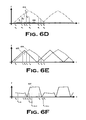
- FIG. 6D signal processing differences are elaborated in FIG. 6D for the “non-coherent” signal processing embodiment of ODIS 515 a on a moving platform 300 where the received signal 612 is shown with the unshifted laser local oscillator signal 606 .
- Frequencies represented by f 1 , f 2 , f 3 of FIG. 6D are beat frequency products of heterodyning the received signal 612 with laser local oscillator 606 on the photomixer 506 resulting in signal 654 of FIG. 6A , which then enters the first channel 624 .
- Trace 612 begins at sample time t o which is the point just before the AOM 127 frequency sweep begins, where the AOM 127 imposes no deflection with no frequency encoding.
- Trace 612 is elevated above the trace 606 because, in this particular embodiment, each return signal from the ground over the FOV has been Doppler frequency shifted, induced by motion of the platform 300 . Since trace 606 in FIG. 6D is the unmodulated laser local oscillator frequency, it is flat and always a constant.
- the FOV can be seen to extend from the left edge where the AOM 127 begins its frequency and angle sweep to the right edge where it ends that sweep. Starting at the right edge as noted in trace 612 the AOM 127 then returns over the same ground cells by descending in frequency at the same sweep rate until it again meets the left edge and the same ground cell it began with. Motion of the platform 300 or manipulation of the elevation mirror 136 of VAL 100 a allows for the next ground strip to be illuminated and data collected.
- each TOA associated to a particular frequency will then be associated to a unique angle due to the frequency encoding of AOM 127 and indicated along the base of FIG. 6D as a o , a 1 , a 4 , a 1 , a o . Notice that as time progresses from t o to t 7 that angles are repeated from a o to a o .
- each ground cell is illuminated on the way up in frequency and again by the return sweep on the way down, each being visited by the laser beam 106 twice before progressing to subsequent ground cell strips in the scene. Adjustment to the measured frequency value due to Doppler frequency shift imposed by the ground will be corrected for as discussed below, noting that the Doppler frequency of each ground cell is given by
- f d 2 ⁇ v ⁇ ⁇ cos ⁇ ⁇ ⁇ ( 7 )
- ⁇ is the angle of each ground cell as measured from boresight where the platform 300 velocity vector and boresight are assumed to match
- f d is the measured Doppler frequency
- v is the platform 300 speed
- ⁇ is the transmitted wavelength 106 .
- FIG. 6E-FIG . 6 F further clarify differences between the signal processing of ODIS 515 a as the analogs of traditional LFM shown in FIG. 6B-FIG . 6 C.
- FIG. 6E we see a replica of trace 612 of FIG. 6D , now down-converted to a lower frequency after emerging from the photomixer 506 as trace 654 .
- Trace 602 is the signal from oscillator 200 including VCO 209 . Both 654 and 602 are received by the mixer 636 of the second channel 625 to produce trace 637 of FIG. 6F . Note that the timelines in FIG. 6E and FIG. 6F are correlated.
- FIG. 6D and FIG. 6F imply that samples in time must be stored in order to operate on values after collection for correction and proper image formation. These values, which are frequencies vs. time, become merely numbers as TOAs in digital memory.
- a ground cell at the left edge FOV is measured to have a return frequency as shown in trace 654 modified by Doppler at that angle.
- transmitted light is frequency modulated by the AOM 127 .
- Doppler frequency contributions from the ground increase according to Eq. (7) thereby increasing the slope of the LFM originally imposed only by the AOM 127 .
- the beat frequency 637 of FIG. 6F becomes a maximum due to the received beam 654 of FIG. 6E having swept back down to boresight where the illuminated ground cell Doppler contribution is again largest.
- the swept beam returns to the FOV left edge where the process begins for the next row of ground cells for imaging.
- each ground cell must receive the rise and fall of the saw-tooth waveform typical to standard LFM as both waveforms appropriately combined reveal Doppler and range information.
- each ground cell need only receive a single illumination from the rise or fall of the saw-tooth waveform as no Doppler correction is required.
- the angle channel 624 as the transmitted signal 106 dwells on a ground cell, a received signal similar to trace 612 of FIG. 6D is simultaneously received. But, contrary to trace 612 of FIG. 6D , it has no Doppler frequency adjustment. Thus, the trace of 612 for a stationary platform would have constant slope up and down as determined by the AOM 127 alone.
- the beat frequency between 606 and 612 would therefore be converted to TOAs by the SAW 630 and become measured data in unique time values corresponding to unique angles.
- a received signal 654 and signal 602 from the VCO 209 are received by the mixer 636 of FIG. 6A .
- Mixing the signal 654 of FIG. 6G with the signal 602 creates the beat frequency 631 of FIG. 6H .
- the timelines in FIG. 6G and FIG. 6H are correlated.
- Each ground cell will have just such a beat frequency proportional to range which is then converted into measurements in time by the SAW 630 .
- the traditional LFM beat frequency is proportional to range given the sweep rate and relationship between and travel time over range at the speed of light.
- the ODIS 515 a on a moving platform 300 is a SAW-based receiver.
- the SAWs 630 require no power, are inexpensive, and are readily commercially available. It has two-IF-receive channels 624 and 625 and has one receive channel 624 providing azimuth data by converting frequency to time in the SAW 630 while another receive channel 625 provides range by a similar method. It also places the AOM 127 after the transmit beam splitter 603 .
- the ODIS 515 a frequency modulates the final transmit laser signal 106 using the AOM 127 .
- the modulated reflected return signal 612 (modulated by the AOM 127 on transmit and by platform motion) is mixed on the photomixer 506 with the optical local oscillator which is the laser signal 606 unmodulated by the AOM 127 and thus produces an intermediate frequency (“IF”).
- This IF frequency is the difference frequency between the incoming reflected return signal 612 and the optical local oscillator 606 , also known as the beat frequency 654 .
- the ODIS 515 a splits the IF signal and delivers a half portion to the azimuth channel 624 . It converts the IF frequency received to a pulse emerging from a SAW 630 at a time dependent upon that input IF frequency. This time corresponds to an angle. Since the IF difference frequency changes with angle, so does the time of the pulse out of the SAW 630 . It splits and delivers a half portion of the IF signal for the range channel 625 . And, it delivers a portion of the oscillator 200 output that drives the AOM 127 frequency modulation to an RF mixer 636 which receives both this VCO 209 output and the half portion of IF signal destined for the range channel 625 .
- the IF difference frequency is a ramp in frequency over time and so is the oscillator 200 output. This is because the IF ramp comes from the VCO 209 to begin with. For a stationary platform they would be identically sloped ramps. For a moving platform the IF ramp has an additional slope by virtue of induced Doppler. Ignoring Doppler, the IF and VCO ramps will differ upon target signal reception by an amount proportional to round trip transit time commonly known in the art as LFM ranging. That is, while the VCO 209 has imposed a frequency shift on the transmit signal via the AOM 127 , the VCO 209 continues to frequency sweep as that last bit of transmit signal goes out and comes back.
- the VCO 209 on-board has moved on to a new frequency.
- mixing the IF ramp with the VCO ramp results in a difference frequency proportional to the round trip time which, given the speed of light, is then proportional to range.
- the ODIS 515 a converts the new IF/VCO IF frequency to a pulse emerging from the SAW 630 at a time dependent upon that input IF frequency. This time corresponds to a range. It then performs numerical manipulation and calculation of stored range and angle data to correct for Doppler frequency returns which adjust measured TOAs as representations of frequencies of range and angle.
- the non-coherent signal processing embodiment of ODIS 515 a of FIG. 6A places the AOM 127 after the beam splitter 603 while the coherent signal processing embodiment ODIS 515 b of FIG. 7A places the AOM 127 before the beam splitter 603 . Doing so results in a variation in signal processing required to derive angle. While the first non-coherent embodiment measures angle directly from frequency encoding of the AOM 127 , another means is available which does not measure angle but rather calculates it based on available data as presented here as the coherent signal processing version of ODIS 515 b . Placement of the AOM 127 may be used in either manner, before or after the beam splitter in either the non-coherent embodiment or coherent embodiment with a suitable change to processing employed for angle finding.
- the coherent embodiment 700 includes a VAL transmitter 100 b and an ODIS receiver 515 b .
- the beam splitter 603 is placed “after” the AOM 127 .
- the ODIS receiver 515 includes two channels 703 , 704 .
- Each of the channels 703 , 704 comprises a lowpass filter 712 sandwiched between two low noise amplifiers 709 and an ADC 715 .
- the first channel 703 receives a portion of the reflected return signal 612 and the output of a second local oscillator 718 .
- the second channel 704 receives a second portion of the reflected return signal 612 and the output of the second local oscillator 718 phase-shifted by 90° as is a common means in the art of deriving I and Q data for Doppler signal processing.
- the feed signals are mixed by RF mixers 721 .
- the same process is then applied to pairs of stored values on the same physical side of boresight, which in trace 612 of FIG. 7B may appear to be on opposite sides of boresight.
- the first value after t o and the last before t 7 labeled respectively as t a — up and t a — dn in trace 717 of FIG. 7B are paired in Eq. (10) and Eq. (11) as these two values represent the same ground cell, visited by the transmit beam on the way up and once again on the sweep down.
- t b up and t b — dn in trace 717 .
- each ground cell must receive the rise and fall saw-tooth waveform typical to standard LFM as both waveforms appropriately combined reveal Doppler and range information.
- each ground cell need only receive a single illumination from the rise or fall of the saw-tooth waveform as no Doppler correction is required, just as was seen in the non-coherent processing embodiment.
- the implementation for range measurement will be that of traditional LFM shown in FIG. 6G-FIG . 6 H as measured in channels 703 and 704 of FIG. 7A . Note that the timelines in FIG. 6G and FIG. 6H are correlated. As the transmitted laser 106 dwells on a ground cell, a received signal 654 of FIG. 6G is simultaneously received with no Doppler frequency adjustment.
- the coherent embodiment correlates the angle command to the AOM 127 as this angle relates to the platform aspect. More specifically, when the ODIS 515 b digital processor commands a certain angle that value then becomes the angle to which range and cell magnitude data is related as that data is simultaneously received.
- traditional LFM beat frequency is proportional to range given the sweep rate and relationship between and travel time over range at the speed of light.
- Mixing 654 of FIG. 6G with 602 creates the beat frequency 631 of FIG. 6H . Note that the timelines in FIG. 6G and FIG. 6H are correlated. Each ground cell will have just such a beat frequency proportional to range which is then converted into measurements in time by the SAW 630 .
- the coherent processing embodiment need not add channels to uniquely define angle by encoded frequency.
- the ODIS 515 b is a standard mixer-based RF receiver after the optical photomixer 506 . It places the AOM 127 before the transmit beam splitter 603 . It also frequency modulates the transmit VCO 209 and with the AOM 127 . And, it employs LFM over the azimuth of the transmitted laser signal 106 , that is, in one-dimension across the line of sight.
- ODIS 515 is an optical imaging system conforming to high speed, sleek radomes via its flush mounted optics, as opposed to high drag hemispherical domes. It allows full forward imaging of a ground scene (unlike radar DBS which has a blind zone or SAR which looks to the side of boresight) thus allowing to-target guidance, not trajectory shaping as used in DBS and SAR. And uses only one phase sensitive optical receiver channel 503 .
- the ODIS 515 images using only one photomixer as its receiver detector—located at the end of the lone optical channel 418 as opposed to imaging systems that use charge-coupled devices (“CCDs”) or FPAs with many thousands of pixels.
- CCDs charge-coupled devices
- FPAs FPAs with many thousands of pixels.
- CCDs charge-coupled devices
- it uses only “one pixel” to image a 2-D scene. It can image whether in motion or motionless (unlike SAR or DBS that must be on moving platforms) because of the frequency modulation imparted by the AOM 127 of the VAL transmitter 100 . It can also image in any direction.
- the ODIS 515 uses the VAL transmitter 100 as the transmitter/scanner, which is an on-board laser, as transmitter for ground illumination.
- the illustrated embodiments employ a continuous wave laser rather than a pulsed laser. This eliminates heavy, voluminous, and costly pulse modulation hardware. It also uses a “coherent processor” and uses “coherent detection” in a heterodyne process on the photomixer surface. If in motion, it can employ sub-beam resolution in the same way DBS does because each point will have associated with it a fixed AOM frequency and different Doppler frequencies within the beam due to their different relative motions.
- the ODIS 515 performs two functions, 1) scans the transmit laser beam in azimuth, 2) encodes a frequency modulation leveraged in processing (a characteristic of VAL, which ODIS uses). It also performs numerical manipulations to data for correction and compensation depending on operational conditions. Note that not all embodiments will necessarily exhibit all these characteristics. Furthermore, some alternative embodiments may manifest characteristics in addition to or in lieu of those set forth above for the illustrated embodiment.
- FIG. 8 depicts, in a conceptualized block diagram, selected portions of the electronics 800 with which certain aspects of the present invention may be implemented.
- the electronics 800 include a processor 803 communicating with some storage 806 over a bus system 809 .
- the electronics 800 will handle lots of data in relatively short time frames.
- some kinds of processors are more desirable than others for implementing the processor 805 than others.
- DSP digital signal processor
- the processor 803 may be implemented as a processor set, such as a microprocessor with a math co-processor.
- the storage 806 may be implemented in conventional fashion and may include a variety of types of storage, such as a hard disk and/or random access memory (“RAM”) and/or removable storage such as a magnetic disk (not shown) or an optical disk (also not shown).
- RAM random access memory
- the storage 806 will typically involve both read-only and writable memory.
- the storage 806 will typically be implemented in magnetic media (e.g., magnetic tape or magnetic disk), although other types of media may be employed in some embodiments (e.g., optical disk).
- the present invention admits wide latitude in implementation of the storage 806 in various embodiments. In the illustrated embodiment, the storage 806 is implemented in RAM and in cache.
- the storage 806 is encoded with an operating system 821 .
- the processor 803 runs under the control of the operating system 821 , which may be practically any operating system known to the art.
- the storage 806 is also encoded with an application 842 in accordance with the present invention.
- the application 824 is invoked by the processor 803 under the control of the operating system 821 .
- the application 824 when executed by the processor 803 , performs the process of the invention described more fully above.
- the storage 806 includes a data storage 827 comprising a data structure that may be any suitable data structure known to the art.
- the inputs A 1 -A x in FIG. 8 represent the outputs of the channels 624 - 626 in FIG. 6 and 703 - 704 in FIG. 7A .
- the data received from the inputs A 1 -A x is stored in the data storage 827 .
- the application 824 when invoked, performs the methods described elsewhere associated with the operation of the platform 303 with the VAL transmitter 100 in the first and second modes. Note that this operation comprises the execution of the application, and is therefore software implemented. As those in the art having the benefit of this disclosure will appreciate, such a functionality may be implemented in hardware, software, or some combination of the two, depending on the implementation. In the illustrated embodiment, the functionality is implemented in software.
- the software implemented aspects of the invention are typically encoded on some form of program storage medium or implemented over some type of transmission medium.
- the program storage medium may be magnetic (e.g., a floppy disk or a hard drive) or optical (e.g., a compact disk read only memory, or “CD ROM”), and may be read only or random access.
- the transmission medium may be twisted wire pairs, coaxial cable, optical fiber, or some other suitable transmission medium known to the art. The invention is not limited by these aspects of any given implementation.
Abstract
Description
V=ΛF (1)
where:
where:
-
- the
VAL transmitter 100 is composed of a longitudinallymovable laser 103, anAOM 127 driven by apiezo modulator 200, anexpansion lens 130, anadjustable mirror 136, aflat mirror 133 and various mounting objects. - longitudinal movement of the
laser 103 results in laser beamwidth adjustment due to theexpansion lens 130. - by virtue of its piezo-
drive 200, theAOM 127 shifts thelaser beam 106 in azimuth for azimuth scanning. - by virtue of its piezo-
drive 200, theAOM 127 can vary signal amplitude for signal to noise ratio (“SNR”) or low probability of intercept (“LPI”) management. - azimuthal movement imparted by the
AOM 127 is amplified by theexpansion lens 130, thus reducing stress on theAOM 127 and improving loss performance. - the
AOM 127 shifts thelaser signal 106 in frequency as thelaser signal 106 moves in azimuth, thus encoding azimuth angle with frequency. - the
adjustable mirror 136 scans thelaser signal 106 in elevation. - by virtue of its piezo-
drive 200, theAOM 127 can be varied in amplitude allowing a tag to be attached to transmissions of each elevation angle. This variation in transmit signal allows an additional encoding method—generally some AM format—giving AM sidebands at some modulation frequency away from the carrier. - the
VAL transmitter 100 provides five degrees of freedom where most scanners provide two—namely, azimuth sweep, elevation sweep, frequency sweep, beamwidth management, and amplitude modulation.
Note that not all embodiments will exhibit all these characteristics. Furthermore, some alternative embodiments may manifest characteristics in addition to or in lieu of those set forth above for the illustrated embodiment.
- the
where this frequency is represented by the lower plateau of
where R, fr, c, v, and λ are defined as above and this frequency is represented by the higher plateau of
where R, c, fb-up, fb-dn, and fr are defined as above. Subtraction of the up and down beat frequencies yields the velocity v of a point target:
where θ is the angle of each ground cell as measured from boresight where the
where R, fr, c, v and λ are defined above. For the down sweep:
Likewise, following Eq. (5) and Eq. (6) with suitable changes in frequency subscripts for t1 and t5, range and velocity on boresight where maximum Doppler occurs at boresight of
-
- scanning and frequency encoding could be performed in separate steps in some embodiments, for example, by frequency encoding and then holding that encoding while scanning the mirror for example
- one might instead or might additionally encode with angle of transmission in elevation, e.g., encode in azimuth and elevation with crossed AOMs or a composite AOM, both of which are commercially available;
- frequency encoding is not needed for the coherent processing mode if one uses two mirrors and no AOM;
- the laser may be any kind of coherent laser could be used (e.g., fiber, diode, gas) that is continuous wave or even pulsed, provided that there is continuous sine wave connection from one pulse to the next (i.e., they are coherent pulse to pulse)
- it is not limited to narrow beam, high gain laser signals, but can manage the beam width and can create a wider low gain beam if it needs one; and
- it can scan in azimuth, in elevation, or in both azimuth and elevation.
It is therefore evident that the particular embodiments disclosed above may be altered or modified and all such variations are considered within the scope and spirit of the invention. Accordingly, the protection sought herein is as set forth in the claims below.
Claims (20)
Priority Applications (1)
| Application Number | Priority Date | Filing Date | Title |
|---|---|---|---|
| US12/932,113 US8525974B2 (en) | 2006-01-18 | 2011-02-17 | Omni-directional imaging sensor |
Applications Claiming Priority (3)
| Application Number | Priority Date | Filing Date | Title |
|---|---|---|---|
| US75999906P | 2006-01-18 | 2006-01-18 | |
| US11/616,614 US7894042B2 (en) | 2006-01-18 | 2006-12-27 | Omni-directional imaging sensor |
| US12/932,113 US8525974B2 (en) | 2006-01-18 | 2011-02-17 | Omni-directional imaging sensor |
Related Parent Applications (1)
| Application Number | Title | Priority Date | Filing Date |
|---|---|---|---|
| US11/616,614 Continuation US7894042B2 (en) | 2006-01-18 | 2006-12-27 | Omni-directional imaging sensor |
Publications (2)
| Publication Number | Publication Date |
|---|---|
| US20120218539A1 US20120218539A1 (en) | 2012-08-30 |
| US8525974B2 true US8525974B2 (en) | 2013-09-03 |
Family
ID=38684609
Family Applications (2)
| Application Number | Title | Priority Date | Filing Date |
|---|---|---|---|
| US11/616,614 Expired - Fee Related US7894042B2 (en) | 2006-01-18 | 2006-12-27 | Omni-directional imaging sensor |
| US12/932,113 Expired - Fee Related US8525974B2 (en) | 2006-01-18 | 2011-02-17 | Omni-directional imaging sensor |
Family Applications Before (1)
| Application Number | Title | Priority Date | Filing Date |
|---|---|---|---|
| US11/616,614 Expired - Fee Related US7894042B2 (en) | 2006-01-18 | 2006-12-27 | Omni-directional imaging sensor |
Country Status (1)
| Country | Link |
|---|---|
| US (2) | US7894042B2 (en) |
Cited By (3)
| Publication number | Priority date | Publication date | Assignee | Title |
|---|---|---|---|---|
| US8897654B1 (en) * | 2012-06-20 | 2014-11-25 | The United States Of America As Represented By The Administrator Of The National Aeronautics And Space Administration | System and method for generating a frequency modulated linear laser waveform |
| US9202489B2 (en) | 2014-01-24 | 2015-12-01 | Seagate Technology Llc | Laser mounted on edge of a slider |
| CN110849335A (en) * | 2019-12-06 | 2020-02-28 | 江苏师范大学 | Remote sensing rapid determination method for reservoir capacity of dammed lake water of waterless underground form data |
Families Citing this family (9)
| Publication number | Priority date | Publication date | Assignee | Title |
|---|---|---|---|---|
| US20070247688A1 (en) * | 2006-01-18 | 2007-10-25 | Turner Mark A | Variable-beamwidth angle encoding laser scanner |
| US7701558B2 (en) * | 2006-09-22 | 2010-04-20 | Leica Geosystems Ag | LIDAR system |
| JP5693827B2 (en) * | 2009-06-17 | 2015-04-01 | 株式会社トプコン | Surveying system |
| WO2015108587A2 (en) | 2013-10-22 | 2015-07-23 | Flir Systems, Inc. | System and method for detecting an object or recess on a surface |
| JP6350229B2 (en) * | 2014-11-11 | 2018-07-04 | 三菱電機株式会社 | Guidance device |
| US10296066B2 (en) | 2016-01-25 | 2019-05-21 | Samsung Electronics Co., Ltd. | Semiconductor device, semiconductor system, and method of operating the semiconductor device |
| DE102017110823A1 (en) | 2016-01-25 | 2018-07-26 | Samsung Electronics Co., Ltd. | Semiconductor device, semiconductor system and method of operating the semiconductor device |
| WO2021016797A1 (en) * | 2019-07-29 | 2021-02-04 | 深圳市速腾聚创科技有限公司 | Laser beam emission module and mounting and adjustment method therefor, laser radar, and smart sensing apparatus |
| US11933882B2 (en) * | 2019-08-20 | 2024-03-19 | Institut National D'optique | Method and system for detection and synthetic aperture imaging of a target |
Citations (10)
| Publication number | Priority date | Publication date | Assignee | Title |
|---|---|---|---|---|
| US3661464A (en) | 1970-03-16 | 1972-05-09 | Jorway Corp | Optical interferometer |
| US4309758A (en) * | 1978-08-01 | 1982-01-05 | Imperial Chemical Industries Limited | Driverless vehicle autoguided by light signals and three non-directional detectors |
| US4700301A (en) | 1983-11-02 | 1987-10-13 | Dyke Howard L | Method of automatically steering agricultural type vehicles |
| US5515054A (en) | 1994-04-20 | 1996-05-07 | Westinghouse Electric Corp. | Dual mode radar transparency and method of fabricating same |
| US20020024331A1 (en) | 2000-04-17 | 2002-02-28 | Harvey Lewis | Method of investigating vibrations and an apparatus therefor |
| US20030137669A1 (en) | 2001-08-03 | 2003-07-24 | Rollins Andrew M. | Aspects of basic OCT engine technologies for high speed optical coherence tomography and light source and other improvements in optical coherence tomography |
| US20040252288A1 (en) | 1999-07-14 | 2004-12-16 | Kacyra Ben K. | Advanced applications for 3-D autoscanning lidar system |
| US20050052656A1 (en) | 2003-08-18 | 2005-03-10 | Michael Lindner | Interferometric measuring device for recording geometric data for surfaces |
| US20050088644A1 (en) | 2001-04-04 | 2005-04-28 | Morcom Christopher J. | Surface profile measurement |
| US20060038977A1 (en) | 2004-08-20 | 2006-02-23 | Lockheed Martin Corporation | Doppler tracking optical monopulse |
-
2006
- 2006-12-27 US US11/616,614 patent/US7894042B2/en not_active Expired - Fee Related
-
2011
- 2011-02-17 US US12/932,113 patent/US8525974B2/en not_active Expired - Fee Related
Patent Citations (10)
| Publication number | Priority date | Publication date | Assignee | Title |
|---|---|---|---|---|
| US3661464A (en) | 1970-03-16 | 1972-05-09 | Jorway Corp | Optical interferometer |
| US4309758A (en) * | 1978-08-01 | 1982-01-05 | Imperial Chemical Industries Limited | Driverless vehicle autoguided by light signals and three non-directional detectors |
| US4700301A (en) | 1983-11-02 | 1987-10-13 | Dyke Howard L | Method of automatically steering agricultural type vehicles |
| US5515054A (en) | 1994-04-20 | 1996-05-07 | Westinghouse Electric Corp. | Dual mode radar transparency and method of fabricating same |
| US20040252288A1 (en) | 1999-07-14 | 2004-12-16 | Kacyra Ben K. | Advanced applications for 3-D autoscanning lidar system |
| US20020024331A1 (en) | 2000-04-17 | 2002-02-28 | Harvey Lewis | Method of investigating vibrations and an apparatus therefor |
| US20050088644A1 (en) | 2001-04-04 | 2005-04-28 | Morcom Christopher J. | Surface profile measurement |
| US20030137669A1 (en) | 2001-08-03 | 2003-07-24 | Rollins Andrew M. | Aspects of basic OCT engine technologies for high speed optical coherence tomography and light source and other improvements in optical coherence tomography |
| US20050052656A1 (en) | 2003-08-18 | 2005-03-10 | Michael Lindner | Interferometric measuring device for recording geometric data for surfaces |
| US20060038977A1 (en) | 2004-08-20 | 2006-02-23 | Lockheed Martin Corporation | Doppler tracking optical monopulse |
Cited By (5)
| Publication number | Priority date | Publication date | Assignee | Title |
|---|---|---|---|---|
| US8897654B1 (en) * | 2012-06-20 | 2014-11-25 | The United States Of America As Represented By The Administrator Of The National Aeronautics And Space Administration | System and method for generating a frequency modulated linear laser waveform |
| US20150104193A1 (en) * | 2012-06-20 | 2015-04-16 | U.S.A. As Represented By The Administrator Of The National Aeronautics And Space Administration | System and Method for Generating A Frequency Modulated Linear Laser Waveform |
| US9712250B2 (en) * | 2012-06-20 | 2017-07-18 | The United States Of America As Represented By The Administrator Of The National Aeronautics And Space Administration | System and method for generating a frequency modulated linear laser waveform |
| US9202489B2 (en) | 2014-01-24 | 2015-12-01 | Seagate Technology Llc | Laser mounted on edge of a slider |
| CN110849335A (en) * | 2019-12-06 | 2020-02-28 | 江苏师范大学 | Remote sensing rapid determination method for reservoir capacity of dammed lake water of waterless underground form data |
Also Published As
| Publication number | Publication date |
|---|---|
| US20070262896A1 (en) | 2007-11-15 |
| US20120218539A1 (en) | 2012-08-30 |
| US7894042B2 (en) | 2011-02-22 |
Similar Documents
| Publication | Publication Date | Title |
|---|---|---|
| US8525974B2 (en) | Omni-directional imaging sensor | |
| US11422266B2 (en) | Beam-steering devices and methods for LIDAR applications | |
| US8089617B2 (en) | Energy efficient laser detection and ranging system | |
| KR20230159899A (en) | Method and system for scanning of coherent lidar with fan of collimated beams | |
| EP4001964A1 (en) | Lidar system | |
| US4929951A (en) | Apparatus and method for transform space scanning imaging | |
| US11579264B2 (en) | Optoelectronic sensor, method and vehicle | |
| US11054524B2 (en) | Optimizing a lidar system using sub-sweep sampling | |
| CN111190192B (en) | Airborne array three-dimensional coherent scanning laser radar | |
| US8194306B2 (en) | Variable- beamwidth angle encoding laser scanner | |
| US20190049565A1 (en) | System and Method for Depth Sensing | |
| CN111190189B (en) | Multifunctional double frequency modulation coherent laser radar | |
| US11592562B2 (en) | Continuous-wave light detection and ranging (LiDAR) system | |
| JP2000338244A (en) | Coherent laser radar device | |
| US20220404498A1 (en) | Distance and speed measuring apparatus | |
| Goyette et al. | X-band ISAR imagery of scale-model tactical targets using a wide-bandwidth 350GHz compact range | |
| CN104297759A (en) | Hyperbolic wave forward difference self-scanning direct-view synthetic aperture laser imaging radar | |
| CN114442117A (en) | High-resolution flash lidar imaging system | |
| US20240103173A1 (en) | Multiplexed Light Detection and Ranging Apparatus | |
| US20220236418A1 (en) | Lidar system comprising an interferential diffractive element and lidar imaging method | |
| CN112147636B (en) | Laser radar and detection method thereof | |
| US11892566B1 (en) | Multiplexed light detection and ranging apparatus | |
| CN117008089A (en) | Optical transceiver based on planar waveguide chip and laser radar | |
| CN116973926A (en) | Laser radar | |
| CN112147636A (en) | Laser radar and detection method of laser radar |
Legal Events
| Date | Code | Title | Description |
|---|---|---|---|
| AS | Assignment |
Owner name: LOCKHEED MARTIN CORPORATION, TEXAS Free format text: ASSIGNMENT OF ASSIGNORS INTEREST;ASSIGNORS:TURNER, MARK A;WILLIAMS, BRETT A;SIGNING DATES FROM 20120426 TO 20120504;REEL/FRAME:028238/0981 |
|
| STCF | Information on status: patent grant |
Free format text: PATENTED CASE |
|
| CC | Certificate of correction | ||
| FPAY | Fee payment |
Year of fee payment: 4 |
|
| FEPP | Fee payment procedure |
Free format text: MAINTENANCE FEE REMINDER MAILED (ORIGINAL EVENT CODE: REM.); ENTITY STATUS OF PATENT OWNER: LARGE ENTITY |
|
| LAPS | Lapse for failure to pay maintenance fees |
Free format text: PATENT EXPIRED FOR FAILURE TO PAY MAINTENANCE FEES (ORIGINAL EVENT CODE: EXP.); ENTITY STATUS OF PATENT OWNER: LARGE ENTITY |
|
| STCH | Information on status: patent discontinuation |
Free format text: PATENT EXPIRED DUE TO NONPAYMENT OF MAINTENANCE FEES UNDER 37 CFR 1.362 |
|
| FP | Lapsed due to failure to pay maintenance fee |
Effective date: 20210903 |