US8550761B2 - Drill pipe handling and moving system - Google Patents
Drill pipe handling and moving system Download PDFInfo
- Publication number
- US8550761B2 US8550761B2 US12/966,828 US96682810A US8550761B2 US 8550761 B2 US8550761 B2 US 8550761B2 US 96682810 A US96682810 A US 96682810A US 8550761 B2 US8550761 B2 US 8550761B2
- Authority
- US
- United States
- Prior art keywords
- pipe
- handling system
- drill
- sled
- drill pipe
- Prior art date
- Legal status (The legal status is an assumption and is not a legal conclusion. Google has not performed a legal analysis and makes no representation as to the accuracy of the status listed.)
- Active
Links
Images


Classifications
-
- E—FIXED CONSTRUCTIONS
- E21—EARTH DRILLING; MINING
- E21B—EARTH DRILLING, e.g. DEEP DRILLING; OBTAINING OIL, GAS, WATER, SOLUBLE OR MELTABLE MATERIALS OR A SLURRY OF MINERALS FROM WELLS
- E21B19/00—Handling rods, casings, tubes or the like outside the borehole, e.g. in the derrick; Apparatus for feeding the rods or cables
- E21B19/14—Racks, ramps, troughs or bins, for holding the lengths of rod singly or connected; Handling between storage place and borehole
- E21B19/15—Racking of rods in horizontal position; Handling between horizontal and vertical position
- E21B19/155—Handling between horizontal and vertical position
-
- E—FIXED CONSTRUCTIONS
- E21—EARTH DRILLING; MINING
- E21B—EARTH DRILLING, e.g. DEEP DRILLING; OBTAINING OIL, GAS, WATER, SOLUBLE OR MELTABLE MATERIALS OR A SLURRY OF MINERALS FROM WELLS
- E21B19/00—Handling rods, casings, tubes or the like outside the borehole, e.g. in the derrick; Apparatus for feeding the rods or cables
- E21B19/20—Combined feeding from rack and connecting, e.g. automatically
Definitions
- Drilling masts are the vertical structures used to support the drill string while a well is being drilled. Masts are usually rectangular in shape as opposed to the generally pyramidal shape of a derrick. The rectangular shape offers very good stiffness that allows the mast to be moved to a horizontal position for transport. Thus, drilling masts are very common on portable land rigs.
- Drilling masts also often have relatively compact footprints, which often limit space available for the vertical storage of pipe.
- a storage area for vertical pipe is often provided immediately adjacent to the drilling mast.
- the movement of the drill pipe to the fingerboard is often effectuated by rig personnel pulling or pushing the drill pipe to its proper location. Such movements of large sections of drill pipe can be hazardous to the rig personnel, both near the drilling mast's fingerboard and below at the drill floor.
- automating pipe handling procedures can eliminate personnel from the drilling mast at the pipe racker and from the drill floor at the setback handler, thereby alleviating safety concerns.
- removably coupling pipe handling components to the drilling mast can ease constraints on the limited drilling mast footprint.
- FIGS. 1-10 illustrate side elevation views of a pipe racking system constructed in accordance with embodiments of the present invention
- FIGS. 11-15 illustrate top-down views of additional embodiments of the pipe racking system of FIGS. 1-10 ;
- FIG. 16 illustrates a side elevation view of the mechanism of one embodiment of the pipe racking system of FIGS. 1-16 ;
- FIGS. 17A-34 illustrate side elevation and top-down views of a setback handling system constructed in accordance with embodiments of the present invention.
- FIGS. 35-40 illustrate a setback handling system constructed in accordance with further embodiments of the present invention.
- any use of any form of the terms “connect”, “engage”, “couple”, “attach”, or any other term describing an interaction between elements is not meant to limit the interaction to direct interaction between the elements and may also include indirect interaction between the elements described.
- Reference to the term “drill pipe” includes a variety of oilfield tubulars, including drill pipe, drill collars, casing, and tubing. Reference to the term “drilling mast” may also include other drilling structures extending above a drill floor to support equipment for downhole operations.
- the terms “including” and “comprising” are used in an open-ended fashion, and thus should be interpreted to mean “including, but not limited to . . . ”.
- an embodiment of a pipe racking system 10 comprises frame 12 , carriage 14 , column 16 , and gripping arm 18 .
- Racking system 10 is coupled to mast 20 above fingerboard 22 .
- Gripping arm 18 is supported on the lower end of column 16 , which extends downward from carriage 14 .
- Carriage 14 is supported by frame 12 and moves column 16 and gripping arm 18 so as to move pipe 24 from well center into fingerboard 22 .
- Column 16 controls the vertical and rotational position of gripping arm 18 so that the gripping arm can engage pipe 24 at the proper height and move the pipe into its proper location within fingerboard 22 .
- FIGS. 2-6 illustrate the installation of pipe racking system 10 onto mast 20 .
- racking system 10 can be transported to a drilling site on trailer 26 .
- Racking system 10 is unloaded from the trailer, such as by a forklift, and set in an upright position where it can be pinned to mast 20 , which is in a horizontal position, as shown in FIG. 3 .
- gripping arm 18 is decoupled from its storage lock 28 on frame 12 and raised slightly to clear frame 12 .
- Column 16 is also raised for clearance from frame 12 .
- Carriage 14 is rotated or pivoted until wheels 30 engage track 32 on frame 12 , as shown in FIG. 5 .
- Carriage locks 34 are then released to allow carriage 14 to move relative to frame 12 , as shown in FIG. 6 .
- FIGS. 7-15 illustrate racking system 10 engaging pipe 24 for movement of the pipe into fingerboard 22 .
- FIG. 7 illustrates pipe 24 disconnected from the drill string and supported by elevator 34 in a vertical position ready to be moved from well center.
- the lower end of pipe 24 is first moved off of well center to the setback under fingerboard 22 .
- gripping arm 18 is then extended so that grip jaw 36 engages pipe 24 below elevator 34 .
- elevator 34 can be released so that the pipe is supported by racking system 10 , as shown in FIG. 10 .
- FIGS. 11-13 are now referred to, wherein the view is shifted to substantially above the system 10 and fingerboard 22 .
- gripping arm 18 is rotated (shown in FIG. 12 ) and retracted (shown in FIG. 13 ) so as to move the pipe into fingerboard 22 . Gripping arm 18 is then extended to move pipe 24 into its proper storage position within fingerboard 22 , as shown in FIGS. 14-15 . Once pipe 24 is stored, racking system 10 is returned to its starting position and is ready to engage the next stand of drill pipe.
- Carriage 14 comprises bridge 40 , articulated arm 42 , and actuator or control cylinder 44 .
- Bridge 40 is supported on frame 12 by wheels 30 .
- Hydraulic cylinder 44 is connected to frame 12 and arm 42 , which is pivotally coupled to the frame and bridge 40 such that extension and retraction of the hydraulic cylinder causes the articulated arm to move the bridge along the frame.
- Column 16 comprises post 50 , vertical actuator or control cylinder 52 , and rotation mechanism 54 .
- Vertical cylinder 52 provides for the adjustment of the vertical position of post 50 .
- Rotation mechanism 54 serves to rotate post 50 about its central axis.
- Gripping arm 18 comprises grip jaw 36 , support arm 60 , pivot arm 62 , and actuator or control cylinder 64 .
- Hydraulic cylinder 64 is coupled to support arm 60 and column 16 such that the vertical extension and retraction of the cylinder results in horizontal movement of grip jaw 36 .
- the pipe racking system 10 shown in FIGS. 1-16 operates to control and position the upper end of a drill pipe stand as it is moved horizontally into and out of a pipe storage area, or setback.
- a setback handling system may be utilized to capture and control the lower end of the drill string in the setback area, thereby eliminating the need for direct involvement of rig personnel.
- the following embodiments of a setback handling system can be used with other drilling structures extending above a drill floor, such as a derrick, and also with a vertical ground racking system wherein the setback area is on the ground or rig floor at the rig site. Description of the embodiments with reference to a drilling mast is for illustrative purposes only.
- FIGS. 17A and 17B illustrate one embodiment of a setback handling system 100 comprising rotating table 102 having pipe guide 104 and pipe mover 106 .
- Rotating table 102 is slidingly disposed on tracks 108 that run through setback rack 110 .
- Setback rack 110 is positioned on drill floor 112 between well center 114 and pipe ramp 116 .
- Setback rack 110 also comprises support beams 118 and capture funnel 120 .
- FIGS. 17A-24B illustrate setback handling system 100 being used to guide single joints of drill pipe 122 into mast 124 , or other drilling structure or rig site, such as would happen during the beginning of drilling operations.
- a top-down view of setback handling system 100 (such as FIG. 17B ) is included along with a side elevation view (such as FIG. 17A ) in order to understand how the system is operating.
- top drive 126 is in its lowest position and has been disconnected from drill string 128 .
- Pipe elevator 130 is swung outward from well center 114 and is engaged with an upper end of drill pipe 122 on pipe ramp 116 .
- Rotating table 102 is moved to its innermost position and pipe guide 104 is oriented toward pipe ramp 116 .
- Top drive 126 is then moved back toward the top of mast 124 along with the elevator and drill pipe 122 , as shown in FIG. 18A .
- table setback handling system 102 is moved toward pipe ramp 116 and pipe guide 104 is extended by actuator 115 so that rollers 132 contact drill pipe 122 , as is shown in FIGS. 19A-20B .
- FIGS. 21A and 21B once drill pipe 122 clears pipe ramp 116 , pipe guide 104 is returned to its upright position ( FIG. 21A ) by actuator 115 and rollers 132 are closed to capture the tailing end of the drill pipe ( FIG. 21B ).
- FIG. 22A once drill pipe 122 is captured, table 102 is moved toward well center 114 . In FIG.
- table 102 is rotated by an actuator so that pipe guide 104 can be extended such that the drill pipe hangs vertically from the elevator (not shown).
- Pipe guide 104 can then be released and retracted (as shown in FIGS. 23A and 23B ) and drill pipe 122 moved to well center 114 by the elevator (not shown) and aligned with drill string 128 (as shown in FIGS. 24A and 24B ).
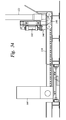
- FIGS. 25A-34B illustrate setback handling system 100 being used during a tripping operation to store drill pipe in the setback area.
- a stand of drill pipe 122 is disconnected from drill string 128 and its lower end is guided to guide funnel 120 by rollers 132 of pipe guide 104 .
- pipe guide 104 is disengaged and table 102 is rotated ninety degrees, shown by arrow 134 , so that pipe mover 106 is aligned with guide funnel 120 .
- pipe mover 106 comprises engagement finger 140 , actuator or lift cylinder 142 , push/pull mechanism 144 , and sled 146 .
- Sled 146 is slidably coupled to table 102 and is moved horizontally by push/pull mechanism 144 .
- push/pull mechanism is a push-pull chain or a rigid chain.
- Engagement finger 140 is moveably mounted to sled 146 such that lift cylinder 142 controls the vertical position of the finger.
- Pipe mover 106 engages drill pipe 122 by raising engagement finger 140 underneath the drill pipe as shown in FIG. 30A .
- Lift cylinder 142 raises engagement finger 140 so that drill pipe 122 clears guide funnel 120 and push/pull mechanism 144 moves sled 146 back toward the center of table 102 as shown in FIGS. 31A and 31B .
- table 102 is then rotated ninety degrees so that sled 146 is aligned with slot 148 between support beams 118 .
- push/pull mechanism 144 moves sled 146 and drill pipe 122 outward to a desired storage position and lowers engagement finger 140 so that the drill pipe is supported on beams 118 .
- FIGS. 35 and 36 illustrate an embodiment of a setback handling system 200 comprising rotating table 202 , pipe guide 204 , and pipe mover 206 .
- Table 202 is slidably mounted on rails 208 that extend through storage beams 210 .
- FIGS. 37-40 illustrate the use of setback handling system 200 in the moving of tubular member 308 from pipe erector 300 to well center 304 .
- Tubular member 308 is moved from a horizontal storage position to a vertical position by pipe erector 300 where it is supported by vertical support structure 302 as shown in FIG. 37 .
- Pipe guide 204 engages tubular member 308 as it is raised above drill floor 306 , as shown in FIG. 38 .
- table 202 rotates and moves toward well center 304 so that tubular member 308 can be picked up and moved to the well center 304 by the elevator (not shown).
- a drilling mast may also refer to other drilling structures extending above a drill floor to support equipment for downhole operations.
- Various disclosed embodiments include a pipe racking system having a modular frame and extendable arm assembly for connection to a drilling mast.
- the assembly includes a grip jaw that can be manipulated to move a drill pipe from a drill string to a stored position and vice versa.
- the manipulation includes at least vertical and rotational movement of any one or all of the arm, grip jaw and drill pipe. Horizontal movements may also be used.
- Certain embodiments include a setback handling system in the setback area for handling the lower end of the drill pipe.
- the setback handling system can be used to manipulate the lower end of the drill pipe for make up with a drill string, or for movement to storage positions in the setback area.
- the setback handling system may include various combinations of a pipe guide, a pipe mover, and a slidable and rotatable table each having actuators for automated movement, along with a setback rack having storage slots for the drill pipe.
- Some embodiments also include a pipe erector and vertical support structure.
- the movements and manipulations of the drill pipe from the drill string to a storage position or vice versa are achieved by using structures that move relative to each other via actuators, such as control cylinders, such that rig personnel is not needed.
- actuators such as control cylinders
Abstract
Description
Claims (15)
Priority Applications (1)
| Application Number | Priority Date | Filing Date | Title |
|---|---|---|---|
| US12/966,828 US8550761B2 (en) | 2007-01-08 | 2010-12-13 | Drill pipe handling and moving system |
Applications Claiming Priority (3)
| Application Number | Priority Date | Filing Date | Title |
|---|---|---|---|
| US87916107P | 2007-01-08 | 2007-01-08 | |
| US11/970,900 US20080164064A1 (en) | 2007-01-08 | 2008-01-08 | Drill pipe handling and moving system |
| US12/966,828 US8550761B2 (en) | 2007-01-08 | 2010-12-13 | Drill pipe handling and moving system |
Related Parent Applications (1)
| Application Number | Title | Priority Date | Filing Date |
|---|---|---|---|
| US11/970,900 Continuation US20080164064A1 (en) | 2007-01-08 | 2008-01-08 | Drill pipe handling and moving system |
Publications (2)
| Publication Number | Publication Date |
|---|---|
| US20110079434A1 US20110079434A1 (en) | 2011-04-07 |
| US8550761B2 true US8550761B2 (en) | 2013-10-08 |
Family
ID=39521479
Family Applications (2)
| Application Number | Title | Priority Date | Filing Date |
|---|---|---|---|
| US11/970,900 Abandoned US20080164064A1 (en) | 2007-01-08 | 2008-01-08 | Drill pipe handling and moving system |
| US12/966,828 Active US8550761B2 (en) | 2007-01-08 | 2010-12-13 | Drill pipe handling and moving system |
Family Applications Before (1)
| Application Number | Title | Priority Date | Filing Date |
|---|---|---|---|
| US11/970,900 Abandoned US20080164064A1 (en) | 2007-01-08 | 2008-01-08 | Drill pipe handling and moving system |
Country Status (6)
| Country | Link |
|---|---|
| US (2) | US20080164064A1 (en) |
| EP (1) | EP1953334B1 (en) |
| BR (1) | BRPI0800669A (en) |
| CA (1) | CA2617028C (en) |
| DK (1) | DK1953334T3 (en) |
| MX (1) | MX2008000353A (en) |
Cited By (24)
| Publication number | Priority date | Publication date | Assignee | Title |
|---|---|---|---|---|
| US10053934B2 (en) | 2014-12-08 | 2018-08-21 | National Oilwell Varco, L.P. | Floor mounted racking arm for handling drill pipe |
| US20190309585A1 (en) * | 2018-04-05 | 2019-10-10 | Travis James Miller | System for handling tubulars on a rig |
| US20190330937A1 (en) * | 2018-04-27 | 2019-10-31 | Nabors Lux 2 Sarl | System and method for conducting subterranean operations |
| US10465455B2 (en) | 2015-11-16 | 2019-11-05 | Schlumberger Technology Corporation | Automated tubular racking system |
| US10519727B2 (en) | 2015-11-17 | 2019-12-31 | Schlumberger Technology Corporation | High trip rate drilling rig |
| US10597954B2 (en) | 2017-10-10 | 2020-03-24 | Schlumberger Technology Corporation | Sequencing for pipe handling |
| US10697255B2 (en) | 2015-11-16 | 2020-06-30 | Schlumberger Technology Corporation | Tubular delivery arm for a drilling rig |
| US10808465B2 (en) | 2018-04-27 | 2020-10-20 | Canrig Robotic Technologies As | System and method for conducting subterranean operations |
| US10844674B2 (en) | 2016-04-29 | 2020-11-24 | Schlumberger Technology Corporation | High trip rate drilling rig |
| US10927603B2 (en) | 2016-04-29 | 2021-02-23 | Schlumberger Technology Corporation | High trip rate drilling rig |
| US11015402B2 (en) | 2018-04-27 | 2021-05-25 | Canrig Robotic Technologies As | System and method for conducting subterranean operations |
| US11035183B2 (en) | 2018-08-03 | 2021-06-15 | National Oilwell Varco, L.P. | Devices, systems, and methods for top drive clearing |
| US11041346B2 (en) | 2018-04-27 | 2021-06-22 | Canrig Robotic Technologies As | System and method for conducting subterranean operations |
| US11118414B2 (en) | 2016-04-29 | 2021-09-14 | Schlumberger Technology Corporation | Tubular delivery arm for a drilling rig |
| US11187049B2 (en) | 2018-09-06 | 2021-11-30 | Schlumberger Technology Corporation | Fingerboard |
| US11274508B2 (en) | 2020-03-31 | 2022-03-15 | National Oilwell Varco, L.P. | Robotic pipe handling from outside a setback area |
| US20220127917A1 (en) * | 2019-01-31 | 2022-04-28 | National Oilwell Varco, L.P. | Tubular string building system and method |
| US11352843B2 (en) | 2016-05-12 | 2022-06-07 | Nov Canada Ulc | System and method for offline standbuilding |
| US11365592B1 (en) | 2021-02-02 | 2022-06-21 | National Oilwell Varco, L.P. | Robot end-effector orientation constraint for pipe tailing path |
| US11454069B2 (en) | 2020-04-21 | 2022-09-27 | Schlumberger Technology Corporation | System and method for handling a tubular member |
| US11591863B2 (en) * | 2018-04-27 | 2023-02-28 | Drillmec Inc. | Multifunction handler for handling drilling elements in a drilling rig, drilling rig and related methods for handling drilling elements |
| US11814911B2 (en) | 2021-07-02 | 2023-11-14 | National Oilwell Varco, L.P. | Passive tubular connection guide |
| US11834914B2 (en) | 2020-02-10 | 2023-12-05 | National Oilwell Varco, L.P. | Quick coupling drill pipe connector |
| US11891864B2 (en) | 2019-01-25 | 2024-02-06 | National Oilwell Varco, L.P. | Pipe handling arm |
Families Citing this family (43)
| Publication number | Priority date | Publication date | Assignee | Title |
|---|---|---|---|---|
| NL1029961C2 (en) * | 2005-09-15 | 2007-03-16 | Balance Point Control B V | Derrick and method for bringing one or more drill pipes into a wellbore with enclosed pressure. |
| EP1953334B1 (en) * | 2007-01-08 | 2016-11-09 | National Oilwell Varco, L.P. | A pipe handling system and method |
| US7802636B2 (en) | 2007-02-23 | 2010-09-28 | Atwood Oceanics, Inc. | Simultaneous tubular handling system and method |
| SG173424A1 (en) | 2008-01-31 | 2011-08-29 | Keppel Offshore & Marine Technology Ct Pte Ltd | Pipe handling system and method |
| WO2010039811A2 (en) * | 2008-09-30 | 2010-04-08 | National Oilwell Varco, L.P. | Pipe section guide system with flexible member |
| GB0907199D0 (en) * | 2009-04-27 | 2009-06-10 | Derrick Services Uk Ltd | An improvement to a derrick |
| US9038733B2 (en) * | 2009-04-29 | 2015-05-26 | Itrec B.V. | Tubulars storage and handling system |
| WO2011031577A2 (en) | 2009-09-09 | 2011-03-17 | National Oilwell Varco, L.P. | Method and apparatus for wind turbine erection |
| US8727690B2 (en) | 2009-09-10 | 2014-05-20 | National Oilwell Varco, L.P. | Windmill handling system and method for using same |
| US8215888B2 (en) | 2009-10-16 | 2012-07-10 | Friede Goldman United, Ltd. | Cartridge tubular handling system |
| US8556003B2 (en) * | 2009-11-18 | 2013-10-15 | National Oilwell Varco, L.P. | Split sub-basement drill rig |
| KR101210589B1 (en) * | 2010-01-19 | 2012-12-11 | 인석신 | drilling machine |
| US8827008B2 (en) | 2010-07-20 | 2014-09-09 | National Oilwell Varco, L.P. | Inflatable restraint system |
| US20120073831A1 (en) * | 2010-09-27 | 2012-03-29 | Robert Gibbens | Mud saver mat for rig floors and other areas |
| WO2012061506A2 (en) | 2010-11-02 | 2012-05-10 | National Oilwell Varco Norway As | A drilling system and a device for assembling and disassembling pipe stands |
| CN102536193B (en) * | 2010-12-31 | 2015-09-09 | 中国石油天然气集团公司 | A kind of heavy-load pipe arranging robot |
| US8814487B2 (en) | 2011-02-09 | 2014-08-26 | National Oilwell Varco, L.P. | Impact absorbing access platform for drilling structures |
| US9157286B2 (en) | 2011-10-11 | 2015-10-13 | Warrier Rig Ltd | Portable pipe handling system |
| US9091128B1 (en) * | 2011-11-18 | 2015-07-28 | T&T Engineering Services, Inc. | Drill floor mountable automated pipe racking system |
| WO2013082172A1 (en) * | 2011-11-28 | 2013-06-06 | T&T Engineering Services, Inc. | Tubular stand building and racking system |
| GB201201607D0 (en) * | 2012-01-31 | 2012-03-14 | Larkin Brendan | Drilling-pipe handling apparatus and method |
| CN102606092B (en) * | 2012-03-29 | 2013-11-06 | 吉林大学 | Hanging type adaptive automatic drill pipe string discharge device |
| DE102012007402A1 (en) | 2012-04-16 | 2013-10-17 | Herrenknecht Vertical Gmbh | Pipe bearing and method for feeding and discharging pipe bodies to a drilling rig |
| WO2014078871A1 (en) | 2012-11-19 | 2014-05-22 | Key Energy Services, Llc | Mechanized and automated well service rig |
| US9562407B2 (en) | 2013-01-23 | 2017-02-07 | Nabors Industries, Inc. | X-Y-Z pipe racker for a drilling rig |
| US9476267B2 (en) | 2013-03-15 | 2016-10-25 | T&T Engineering Services, Inc. | System and method for raising and lowering a drill floor mountable automated pipe racking system |
| CN103470192A (en) * | 2013-08-30 | 2013-12-25 | 成都科盛石油科技有限公司 | Double-centralization wellhead pipe fitting device |
| DE102013015893A1 (en) * | 2013-09-24 | 2015-03-26 | Herrenknecht Vertical Gmbh | Handling device for drill pipes of a deep drilling device |
| US9354623B2 (en) | 2014-02-20 | 2016-05-31 | Nabors Industries, Inc. | Methods and systems for pipe management on a drilling rig |
| US9926753B2 (en) * | 2014-05-16 | 2018-03-27 | Nabors Industries, Inc. | Parking system for a pipe racker on a drilling rig |
| US9932783B2 (en) | 2014-08-27 | 2018-04-03 | Nabors Industries, Inc. | Laterally moving racker device on a drilling rig |
| US20160102508A1 (en) * | 2014-10-09 | 2016-04-14 | Nabors Drilling International Limited | Automated bootstrap quad-mast rig |
| US10323473B2 (en) * | 2014-12-10 | 2019-06-18 | Nabors Industries, Inc. | Modular racker system for a drilling rig |
| US9650840B2 (en) | 2015-04-27 | 2017-05-16 | National Oilwell Varco, L.P. | Method and apparatus for erecting a drilling rig |
| NL2014988B1 (en) * | 2015-06-18 | 2017-01-23 | Itrec Bv | A drilling rig with a top drive sytem operable in a drilling mode and a tripping mode. |
| US20180274308A1 (en) | 2015-09-23 | 2018-09-27 | National Oilwell Varco, L.P. | Impact Attenuating Media |
| US10145187B2 (en) * | 2015-12-09 | 2018-12-04 | Nabors Drilling Technologies Usa, Inc. | Pipe handling methodology |
| CN105804677A (en) * | 2016-03-29 | 2016-07-27 | 四川宏华石油设备有限公司 | Pipe processing device |
| CA3061916A1 (en) | 2017-05-16 | 2018-11-22 | National Oilwell Varco, L.P. | Rig-floor pipe lifting machine |
| US11391153B2 (en) * | 2017-08-28 | 2022-07-19 | J.H. Fletcher & Co. | Autonomous roof bolter and related methods |
| GB201718482D0 (en) * | 2017-11-08 | 2017-12-20 | Oiltech Automation Ltd | Method and apparatus for handling drill tubes |
| DK179938B1 (en) | 2018-03-11 | 2019-10-14 | Maersk Drilling A/S | Robotic Apparatus for performing Drill Floor Operations |
| US10724310B2 (en) | 2018-06-08 | 2020-07-28 | Glider Products LLC | Integrated pipe handling system for well completion and production |
Citations (23)
| Publication number | Priority date | Publication date | Assignee | Title |
|---|---|---|---|---|
| US2290247A (en) * | 1941-06-20 | 1942-07-21 | Jr Charles W Perkins | Pipe racker |
| US2535546A (en) | 1948-01-23 | 1950-12-26 | William A Pitts | Kelly handling device |
| US2615681A (en) * | 1950-03-27 | 1952-10-28 | Standard Oil Dev Co | Device for handling pipes |
| US2773605A (en) | 1953-11-12 | 1956-12-11 | Paul A Medearis | Pipe racking apparatus |
| US3105596A (en) * | 1962-05-28 | 1963-10-01 | Paco Corp | Off bearer |
| US3212654A (en) * | 1963-11-21 | 1965-10-19 | Lansing Bagnall Ltd | Apparatus for loading and unloading goods |
| US3633767A (en) * | 1969-08-12 | 1972-01-11 | Dresser Ind | Pipe-racking apparatus for oil well derricks or the like |
| US3747192A (en) | 1971-05-21 | 1973-07-24 | Price Co H C | Handling apparatus for couplings used in application of pipe coatings |
| US3921823A (en) * | 1970-12-15 | 1975-11-25 | Activite Atom Avance | Movement compensating apparatus for floating drilling |
| US4193731A (en) * | 1978-06-28 | 1980-03-18 | Leland Francis Blatt | Adjustable shuttle mount for presses |
| US4397605A (en) | 1979-06-05 | 1983-08-09 | Cowgill Charles F | Mechanized stand handling apparatus for drilling rigs |
| US4428710A (en) * | 1977-08-31 | 1984-01-31 | Grisebach Hans Theodor | Manipulator with a swivel jib |
| US4462733A (en) * | 1982-04-23 | 1984-07-31 | Hughes Tool Company | Beam type racking system |
| US4531875A (en) * | 1982-08-17 | 1985-07-30 | Impro Technologies, Inc. | Automated pipe equipment system |
| EP0234880A2 (en) | 1986-02-21 | 1987-09-02 | Robert Morris | Pipe handling apparatus and method |
| US4715761A (en) | 1985-07-30 | 1987-12-29 | Hughes Tool Company | Universal floor mounted pipe handling machine |
| US4738321A (en) | 1985-07-19 | 1988-04-19 | Brissonneau Et Lotz Marine | Process and apparatus for vertical racking of drilling shafts on a drilling tower |
| US4765401A (en) | 1986-08-21 | 1988-08-23 | Varco International, Inc. | Apparatus for handling well pipe |
| JPH05195683A (en) * | 1992-01-23 | 1993-08-03 | Tone Corp | Rod moving device |
| US20040057815A1 (en) * | 2002-09-25 | 2004-03-25 | Woolslayer Joseph R. | Automated pipe racking process and apparatus |
| US20050118003A1 (en) * | 2003-11-28 | 2005-06-02 | California Natural Products | Automated warehouse row cart and lift |
| WO2006075914A1 (en) | 2005-01-12 | 2006-07-20 | Morten Eriksen | A device for handling of pipes at a drill floor |
| US20110079434A1 (en) * | 2007-01-08 | 2011-04-07 | National Oilwell Varco, L.P. | Drill pipe handling and moving system |
-
2008
- 2008-01-03 EP EP08100044.0A patent/EP1953334B1/en active Active
- 2008-01-03 DK DK08100044.0T patent/DK1953334T3/en active
- 2008-01-07 CA CA2617028A patent/CA2617028C/en active Active
- 2008-01-08 US US11/970,900 patent/US20080164064A1/en not_active Abandoned
- 2008-01-08 BR BRPI0800669-5A patent/BRPI0800669A/en not_active IP Right Cessation
- 2008-01-08 MX MX2008000353A patent/MX2008000353A/en unknown
-
2010
- 2010-12-13 US US12/966,828 patent/US8550761B2/en active Active
Patent Citations (23)
| Publication number | Priority date | Publication date | Assignee | Title |
|---|---|---|---|---|
| US2290247A (en) * | 1941-06-20 | 1942-07-21 | Jr Charles W Perkins | Pipe racker |
| US2535546A (en) | 1948-01-23 | 1950-12-26 | William A Pitts | Kelly handling device |
| US2615681A (en) * | 1950-03-27 | 1952-10-28 | Standard Oil Dev Co | Device for handling pipes |
| US2773605A (en) | 1953-11-12 | 1956-12-11 | Paul A Medearis | Pipe racking apparatus |
| US3105596A (en) * | 1962-05-28 | 1963-10-01 | Paco Corp | Off bearer |
| US3212654A (en) * | 1963-11-21 | 1965-10-19 | Lansing Bagnall Ltd | Apparatus for loading and unloading goods |
| US3633767A (en) * | 1969-08-12 | 1972-01-11 | Dresser Ind | Pipe-racking apparatus for oil well derricks or the like |
| US3921823A (en) * | 1970-12-15 | 1975-11-25 | Activite Atom Avance | Movement compensating apparatus for floating drilling |
| US3747192A (en) | 1971-05-21 | 1973-07-24 | Price Co H C | Handling apparatus for couplings used in application of pipe coatings |
| US4428710A (en) * | 1977-08-31 | 1984-01-31 | Grisebach Hans Theodor | Manipulator with a swivel jib |
| US4193731A (en) * | 1978-06-28 | 1980-03-18 | Leland Francis Blatt | Adjustable shuttle mount for presses |
| US4397605A (en) | 1979-06-05 | 1983-08-09 | Cowgill Charles F | Mechanized stand handling apparatus for drilling rigs |
| US4462733A (en) * | 1982-04-23 | 1984-07-31 | Hughes Tool Company | Beam type racking system |
| US4531875A (en) * | 1982-08-17 | 1985-07-30 | Impro Technologies, Inc. | Automated pipe equipment system |
| US4738321A (en) | 1985-07-19 | 1988-04-19 | Brissonneau Et Lotz Marine | Process and apparatus for vertical racking of drilling shafts on a drilling tower |
| US4715761A (en) | 1985-07-30 | 1987-12-29 | Hughes Tool Company | Universal floor mounted pipe handling machine |
| EP0234880A2 (en) | 1986-02-21 | 1987-09-02 | Robert Morris | Pipe handling apparatus and method |
| US4765401A (en) | 1986-08-21 | 1988-08-23 | Varco International, Inc. | Apparatus for handling well pipe |
| JPH05195683A (en) * | 1992-01-23 | 1993-08-03 | Tone Corp | Rod moving device |
| US20040057815A1 (en) * | 2002-09-25 | 2004-03-25 | Woolslayer Joseph R. | Automated pipe racking process and apparatus |
| US20050118003A1 (en) * | 2003-11-28 | 2005-06-02 | California Natural Products | Automated warehouse row cart and lift |
| WO2006075914A1 (en) | 2005-01-12 | 2006-07-20 | Morten Eriksen | A device for handling of pipes at a drill floor |
| US20110079434A1 (en) * | 2007-01-08 | 2011-04-07 | National Oilwell Varco, L.P. | Drill pipe handling and moving system |
Non-Patent Citations (6)
| Title |
|---|
| Amendment and Response to Office Action dated Jun. 1, 2010 for U.S. Appl. No. 11/970,900, filed Sep. 1, 2010. |
| Amendment and Response to Office Action dated Mar. 25, 2010 for U.S. Appl. No. 11/970,900, filed Apr. 26, 2010. |
| EPO Search Report dated Jul. 3, 2008 for EP Application No. 08100044.0. |
| Final Office Action dated Sep. 13, 2010 for U.S. Appl. No. 11/970,900. |
| Office Action dated Jun. 1, 2010 for U.S. Appl. No. 11/970,900. |
| Office Action dated Mar. 25, 2010 for U.S. Appl. No. 11/970,900. |
Cited By (38)
| Publication number | Priority date | Publication date | Assignee | Title |
|---|---|---|---|---|
| US10526854B2 (en) | 2014-12-08 | 2020-01-07 | National Oilwell Varco, L.P. | Methods for handling pipe |
| US10053934B2 (en) | 2014-12-08 | 2018-08-21 | National Oilwell Varco, L.P. | Floor mounted racking arm for handling drill pipe |
| US10697255B2 (en) | 2015-11-16 | 2020-06-30 | Schlumberger Technology Corporation | Tubular delivery arm for a drilling rig |
| US10465455B2 (en) | 2015-11-16 | 2019-11-05 | Schlumberger Technology Corporation | Automated tubular racking system |
| US10519727B2 (en) | 2015-11-17 | 2019-12-31 | Schlumberger Technology Corporation | High trip rate drilling rig |
| US10550650B2 (en) | 2015-11-17 | 2020-02-04 | Schlumberger Technology Corporation | High trip rate drilling rig |
| US10865609B2 (en) | 2015-11-17 | 2020-12-15 | Schlumberger Technology Corporation | High trip rate drilling rig |
| US11118414B2 (en) | 2016-04-29 | 2021-09-14 | Schlumberger Technology Corporation | Tubular delivery arm for a drilling rig |
| US10844674B2 (en) | 2016-04-29 | 2020-11-24 | Schlumberger Technology Corporation | High trip rate drilling rig |
| US10927603B2 (en) | 2016-04-29 | 2021-02-23 | Schlumberger Technology Corporation | High trip rate drilling rig |
| US11136836B2 (en) | 2016-04-29 | 2021-10-05 | Schlumberger Technology Corporation | High trip rate drilling rig |
| US11352843B2 (en) | 2016-05-12 | 2022-06-07 | Nov Canada Ulc | System and method for offline standbuilding |
| US10597954B2 (en) | 2017-10-10 | 2020-03-24 | Schlumberger Technology Corporation | Sequencing for pipe handling |
| US11346164B2 (en) | 2017-10-10 | 2022-05-31 | Schlumberger Technology Corporation | Sequencing for pipe handling |
| US20190309585A1 (en) * | 2018-04-05 | 2019-10-10 | Travis James Miller | System for handling tubulars on a rig |
| US10995564B2 (en) * | 2018-04-05 | 2021-05-04 | National Oilwell Varco, L.P. | System for handling tubulars on a rig |
| US10808465B2 (en) | 2018-04-27 | 2020-10-20 | Canrig Robotic Technologies As | System and method for conducting subterranean operations |
| US11377914B2 (en) | 2018-04-27 | 2022-07-05 | Canrig Robotic Technologies As | System and method for conducting subterranean operations |
| US11041346B2 (en) | 2018-04-27 | 2021-06-22 | Canrig Robotic Technologies As | System and method for conducting subterranean operations |
| US11015402B2 (en) | 2018-04-27 | 2021-05-25 | Canrig Robotic Technologies As | System and method for conducting subterranean operations |
| US11591863B2 (en) * | 2018-04-27 | 2023-02-28 | Drillmec Inc. | Multifunction handler for handling drilling elements in a drilling rig, drilling rig and related methods for handling drilling elements |
| US11549319B2 (en) | 2018-04-27 | 2023-01-10 | Canrig Robotic Technologies As | System and method for conducting subterranean operations |
| US11506003B2 (en) | 2018-04-27 | 2022-11-22 | Canrig Robotic Technologies As | System and method for conducting subterranean operations |
| US10822891B2 (en) * | 2018-04-27 | 2020-11-03 | Canrig Robotic Technologies As | System and method for conducting subterranean operations |
| US11346163B2 (en) | 2018-04-27 | 2022-05-31 | Canrig Robotic Technologies As | System and method for conducting subterranean operations |
| US20190330937A1 (en) * | 2018-04-27 | 2019-10-31 | Nabors Lux 2 Sarl | System and method for conducting subterranean operations |
| US11613940B2 (en) | 2018-08-03 | 2023-03-28 | National Oilwell Varco, L.P. | Devices, systems, and methods for robotic pipe handling |
| US11035183B2 (en) | 2018-08-03 | 2021-06-15 | National Oilwell Varco, L.P. | Devices, systems, and methods for top drive clearing |
| US11187049B2 (en) | 2018-09-06 | 2021-11-30 | Schlumberger Technology Corporation | Fingerboard |
| US11891864B2 (en) | 2019-01-25 | 2024-02-06 | National Oilwell Varco, L.P. | Pipe handling arm |
| US20220127917A1 (en) * | 2019-01-31 | 2022-04-28 | National Oilwell Varco, L.P. | Tubular string building system and method |
| US11952844B2 (en) * | 2019-01-31 | 2024-04-09 | National Oilwell Varco, L.P. | Tubular string building system and method |
| US11834914B2 (en) | 2020-02-10 | 2023-12-05 | National Oilwell Varco, L.P. | Quick coupling drill pipe connector |
| US11274508B2 (en) | 2020-03-31 | 2022-03-15 | National Oilwell Varco, L.P. | Robotic pipe handling from outside a setback area |
| US11454069B2 (en) | 2020-04-21 | 2022-09-27 | Schlumberger Technology Corporation | System and method for handling a tubular member |
| US11814910B2 (en) | 2020-04-21 | 2023-11-14 | Schlumberger Technology Corporation | System and method for handling a tubular member |
| US11365592B1 (en) | 2021-02-02 | 2022-06-21 | National Oilwell Varco, L.P. | Robot end-effector orientation constraint for pipe tailing path |
| US11814911B2 (en) | 2021-07-02 | 2023-11-14 | National Oilwell Varco, L.P. | Passive tubular connection guide |
Also Published As
| Publication number | Publication date |
|---|---|
| CA2617028A1 (en) | 2008-07-08 |
| BRPI0800669A (en) | 2008-08-26 |
| EP1953334A3 (en) | 2008-11-12 |
| CA2617028C (en) | 2012-03-13 |
| MX2008000353A (en) | 2009-02-23 |
| EP1953334A2 (en) | 2008-08-06 |
| DK1953334T3 (en) | 2016-12-12 |
| EP1953334B1 (en) | 2016-11-09 |
| US20110079434A1 (en) | 2011-04-07 |
| US20080164064A1 (en) | 2008-07-10 |
Similar Documents
| Publication | Publication Date | Title |
|---|---|---|
| US8550761B2 (en) | Drill pipe handling and moving system | |
| US10865609B2 (en) | High trip rate drilling rig | |
| US10465455B2 (en) | Automated tubular racking system | |
| US9951572B2 (en) | X-Y-Z pipe racker for a drilling rig | |
| CN109312606B (en) | High-rise and low-down drilling speed drilling machine | |
| AU2006316335B2 (en) | Integrated top drive and coiled tubing injector | |
| US20070017704A1 (en) | Single joint drilling system | |
| US20200032597A1 (en) | Dual path robotic derrick and methods applicable in well drilling | |
| US10837243B2 (en) | Pipe handling column racker with retractable arm | |
| US10794126B2 (en) | Dual-activity mast | |
| CA2935843C (en) | System and method for raising and lowering a drill floor mountable automated pipe racking system | |
| US20180216413A1 (en) | Telescopic Deployment Mast | |
| US10214975B2 (en) | Vertical pipe handling system and method for its use | |
| US20190145193A1 (en) | Tubular delivery arm for a drilling rig | |
| CA3007178A1 (en) | Dual path robotic derrick and methods applicable in well drilling |
Legal Events
| Date | Code | Title | Description |
|---|---|---|---|
| AS | Assignment |
Owner name: NATIONAL OILWELL VARCO, L.P., TEXAS Free format text: ASSIGNMENT OF ASSIGNORS INTEREST;ASSIGNORS:BELIK, JAROSLAV;SOUCHEK, RICHARD D.;REEL/FRAME:025499/0678 Effective date: 20080116 |
|
| STCF | Information on status: patent grant |
Free format text: PATENTED CASE |
|
| FEPP | Fee payment procedure |
Free format text: PAYOR NUMBER ASSIGNED (ORIGINAL EVENT CODE: ASPN); ENTITY STATUS OF PATENT OWNER: LARGE ENTITY |
|
| FPAY | Fee payment |
Year of fee payment: 4 |
|
| MAFP | Maintenance fee payment |
Free format text: PAYMENT OF MAINTENANCE FEE, 8TH YEAR, LARGE ENTITY (ORIGINAL EVENT CODE: M1552); ENTITY STATUS OF PATENT OWNER: LARGE ENTITY Year of fee payment: 8 |