US856424A - Controlling an electric candy-spinning machine. - Google Patents
Controlling an electric candy-spinning machine. Download PDFInfo
- Publication number
- US856424A US856424A US27714905A US1905277149A US856424A US 856424 A US856424 A US 856424A US 27714905 A US27714905 A US 27714905A US 1905277149 A US1905277149 A US 1905277149A US 856424 A US856424 A US 856424A
- Authority
- US
- United States
- Prior art keywords
- heater
- motor
- candy
- electric
- circuit
- Prior art date
- Legal status (The legal status is an assumption and is not a legal conclusion. Google has not performed a legal analysis and makes no representation as to the accuracy of the status listed.)
- Expired - Lifetime
Links
Images

Classifications
-
- H—ELECTRICITY
- H01—ELECTRIC ELEMENTS
- H01L—SEMICONDUCTOR DEVICES NOT COVERED BY CLASS H10
- H01L23/00—Details of semiconductor or other solid state devices
- H01L23/34—Arrangements for cooling, heating, ventilating or temperature compensation ; Temperature sensing arrangements
- H01L23/345—Arrangements for heating
-
- H—ELECTRICITY
- H01—ELECTRIC ELEMENTS
- H01L—SEMICONDUCTOR DEVICES NOT COVERED BY CLASS H10
- H01L2924/00—Indexing scheme for arrangements or methods for connecting or disconnecting semiconductor or solid-state bodies as covered by H01L24/00
- H01L2924/0001—Technical content checked by a classifier
- H01L2924/0002—Not covered by any one of groups H01L24/00, H01L24/00 and H01L2224/00
Definitions
- the object of my invention is to prevent such'an accident, and to this end it consists in the combination with a candy-spinning machine of the'class described, of an organized claims.
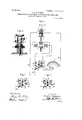
- Figure 1 is a perspective View of an electric candy s inner; ig; 2 is a dia am of the circuits, showing the switch in t e running position; Fig.3 is a detailview on a larger scale showing the brushes which-convey current tothe heater; Fig.- 4 shows the switch turned to cutout the heater, the field coils and armature of the motor being in parallel; and Fig.
- the candy spinner comprises a bowl I mounted on a pedestal 2 in which is an electric motor arranged with its armature shaft. 3 passing up verticallythrough the center of the bowl and carrying at its top a small receptacle 4 for the sugar.
- the receptacle contains an electric heater to melt the sugar, which is thrown out by centrifugal force through the finely perforated walls of the receptacle when,the motor is running. Thespun sugar collects in the bowl, from which it can be removed from time to time.
- the conductors which convey current to the machine are attached to the bindingposts 5, 5, one'of which 5 is connected by a lead 6. with one terminal of the driving motor its terminals connected with the collector rings.
- the drivingmotor is shunt wound, and one terminal common to both the field coils and armature coils, is connected with the lead 6.
- the other terminals of said coils are connected respectively with two stationary twoarmed contacts 12, 13, located concentric with the spindle 14 of a four-way switch lo- 'cated in the pedestal.
- the spindle projects on the outside of saidpedestal and has a handle 15 for manipulating'it. ing dial, visible through a window 16 in the pedestal, showsv the operator the position of the switch.
- the spindle carries two connected radial blades 17, 18 revolving in the plane of the arms a of the contacts 12, 13, and also three connected radial blades 20, 21 insulated from the othertwo andrevolving in the plane of the arms I) of the contacts 12, 13.
- the contact 12 is'a contact 22 which is connectedby a lead 23 with the binding-post 5; and opposite the arm a f the contact 13 is a stationary contact 24 mnnected by a lead 25 with a rheostat arm 26; the coils27 of said rheostat being connected by a lead 28 with the other pair of brushes 7 bearing on the collector.
- ring 9 9.
Description
A. n. ROBINSON. CONTROLLING AN ELECTRIC CANDY SPINNING MACHINE.
APPLICATION FILED SEPT. 6. 1905.
2 SHEETS-SHEET I Fig. I.
Witnesses: Inventor:
/,,, JIlbevt D.Robinson M: V 19 m PATENTED JUNE 11, 1907.
PATENTED JUNE 11, 1907.
A. D. ROBINSON. I CONTROLLING AN ELECTRIC CANDY SPINNING MACHINE.
APPLICATION FILED SEPT. 6. 1905.
2 SHEETS-SHEET z.
Fig. 2.
/4 /7 m 6 3 I .ll l I b Witnesses:
Ihventor" .fflbert. D. Robinson ZZ: W bg UNITED STATES PATENT OFFICE;
ALBERT D. ROBINSON, OF LYNN, MASSACHUSETTS, ASSIGN OR TO GENERAL ELECTRIC COMPANY, A CORPORATION OF NEW YORK.-
CONTROLLING AN ELECTRIC CANDY-SPlNNING MACHINE.
Specification of Letters Patent.
Patented June 11, 1907.
Application filed September 6,1905. Serial No. 277.149.
- To all whom it, may concern:
a receptacle which is rotated rapidly by anelec'tric motor. The molten sugar is thrown out of the receptacle by centrifugal force through small orifices from which it issues in the form of fine thre'ad's,'which are caught and cooled in a bowl concentric with the rotating receptacle In order to avoid burning the sugar,- or overheati the coils of the heater, or short- (aircuiting t cheater when the heating rece ta'cle is removed, it isv necessary to start t e motor before the heater circuit is closed, and
to open the heater circuit either just before or at the same time with the motor circuit. If the heater circuit is controlled by a separate switch from the motor, there is danger that a careless o erator may close it before starting the mac he, or may leave it closed after he has stopped the machine.
1' The object of my invention is to prevent such'an accident, and to this end it consists in the combination with a candy-spinning machine of the'class described, of an organized claims.
' 5 shows the switch turned to cutout the system of circuits together with a peculiar switch for controlling them, as hereinafter set forth and particularly pointed out in the In the accompanying drawings, Figure 1 is a perspective View of an electric candy s inner; ig; 2 is a dia am of the circuits, showing the switch in t e running position; Fig.3 is a detailview on a larger scale showing the brushes which-convey current tothe heater; Fig.- 4 shows the switch turned to cutout the heater, the field coils and armature of the motor being in parallel; and Fig.
armature.
The general construction of the candy spinner is well known. In brief, it comprises a bowl I mounted on a pedestal 2 in which is an electric motor arranged with its armature shaft. 3 passing up verticallythrough the center of the bowl and carrying at its top a small receptacle 4 for the sugar. The receptacle contains an electric heater to melt the sugar, which is thrown out by centrifugal force through the finely perforated walls of the receptacle when,the motor is running. Thespun sugar collects in the bowl, from which it can be removed from time to time.
The conductors which convey current to the machine are attached to the bindingposts 5, 5, one'of which 5 is connected by a lead 6. with one terminal of the driving motor its terminals connected with the collector rings. V
The drivingmotor is shunt wound, and one terminal common to both the field coils and armature coils, is connected with the lead 6. The other terminals of said coils are connected respectively with two stationary twoarmed contacts 12, 13, located concentric with the spindle 14 of a four-way switch lo- 'cated in the pedestal. The spindle projects on the outside of saidpedestal and has a handle 15 for manipulating'it. ing dial, visible through a window 16 in the pedestal, showsv the operator the position of the switch. The spindle carries two connected radial blades 17, 18 revolving in the plane of the arms a of the contacts 12, 13, and also three connected radial blades 20, 21 insulated from the othertwo andrevolving in the plane of the arms I) of the contacts 12, 13. ably at right angles with each other blade 17 being in line with blade 21, and blade 18 op- Opposite the arm of posite to blade 20. the contact 12 is'a contact 22 which is connectedby a lead 23 with the binding-post 5; and opposite the arm a f the contact 13 is a stationary contact 24 mnnected by a lead 25 with a rheostat arm 26; the coils27 of said rheostat being connected by a lead 28 with the other pair of brushes 7 bearing on the collector. ring 9.
When the switch is turned so that neither An indicat- The blades in each set are prefenchine will not run.
of the blades 19,- 20, 2]. is in contact with the l and a single device [or first starting; the mecontact 22, the circuit is open and. the ma On giving the switch a guarter turn to the next position (Fig. 5) the old coils of the motor are energized, but the armature is not in circuit. The next position of the switch (Fig. 4) outs in the armature coils in parallel with the field coils, and starts the motor. The final position of the switch (Fig. 2) outs in the heater 1 1 in multiple with the motor The current flowing through the heater can be regulated by mov ing the rheostatarm 26 which projec s through a slot in the pedestal. N hen the switch is turned to cut out the niotor, the heater also is cut out. It is thus impossible for a careless operator to burn out the heater,
because he must cutit out before the motor can be stopped. Moreover, he cannot unship the receptacle until he stops the motor,
and thus he cannot get a short circuit through the brushes when both brushes bear on the lower collector ring 9, as they will for an in stant during the operation of lifting the hub 10 off the shaft 3. 7
What I claim as new and desire to secure by Letters Patent of the United States, is,-
l. The combination with a power circuit and a heating circuit, of connected means for first closing the power circuit and holding the heating circuit open until after the power circuit is closed, then closin the heating circuit, and'then opening bot circuits simultaneously.
2. The combination with a rotatable receptacle, of an electric motor for driving it,
an electric heater for heating it, and means for insuring. the starting of the motor before the heating circuit can be closed.
3. The combination with a rotatable receptacle, of an electric heater therein, an electric motor for driving said receptacle,
tor. then closing the heater circuit, id then opening both circuits siinullaneousiy.
in a candy spinner, the comhiin'ition with the driving motor and the heater, of means ior insuring the starting oi the motor before the circuit of the heater can he closed.
in acandy spinner, the combination with the driving motor and the heater, of a single means tor ilirst turning the current on the motor and then turning it on to the heater. i
6. The combination with a power circuit and a heating circuit of a controlling switch therefor having a position wherein both circuits are interrupted, a second position wherein the power circuit is closed and the heating circuit open and a final position wherein both circuits are closed.
7. In a candy spinner, the combination. with the driving motor and the heater, of a singleswitch controlling both, and operating to start the motor before the heater is cut into circuit.
8. In a candy spinner, the combination with the driving'motor and the heater, of a switch and circuit connections whereby said motor must be started first, and then the,
heater cut into parallel circuit therewith.
9. In a. candy spinner, the combination with the driving motor and the heater, of a switch and circuit connections whereby current must be supplied first to the motor and afterward to the heater, but the circuits of both will be opened simultaneously.
In witness whereof, I have hereunto set my hand this second day of September, 1905.
ALBERT D. tOBINSON] Witnesses:
Jenn A. ivlcMAinis, Jr., PHILIP F. HARRINGTON, Jr.
Priority Applications (1)
| Application Number | Priority Date | Filing Date | Title |
|---|---|---|---|
| US27714905A US856424A (en) | 1905-09-06 | 1905-09-06 | Controlling an electric candy-spinning machine. |
Applications Claiming Priority (1)
| Application Number | Priority Date | Filing Date | Title |
|---|---|---|---|
| US27714905A US856424A (en) | 1905-09-06 | 1905-09-06 | Controlling an electric candy-spinning machine. |
Publications (1)
| Publication Number | Publication Date |
|---|---|
| US856424A true US856424A (en) | 1907-06-11 |
Family
ID=2924879
Family Applications (1)
| Application Number | Title | Priority Date | Filing Date |
|---|---|---|---|
| US27714905A Expired - Lifetime US856424A (en) | 1905-09-06 | 1905-09-06 | Controlling an electric candy-spinning machine. |
Country Status (1)
| Country | Link |
|---|---|
| US (1) | US856424A (en) |
Cited By (10)
| Publication number | Priority date | Publication date | Assignee | Title |
|---|---|---|---|---|
| US5346377A (en) * | 1993-10-07 | 1994-09-13 | Fuisz Technologies Ltd. | Apparatus for flash flow processing having feed rate control |
| US5445769A (en) * | 1994-06-27 | 1995-08-29 | Fuisz Technologies Ltd. | Spinner head for flash flow processing |
| US5458823A (en) * | 1994-10-28 | 1995-10-17 | Fuisz Technologies Ltd. | Method and apparatus for spinning feedstock material |
| US5549917A (en) * | 1994-07-01 | 1996-08-27 | Fuisz Technologies Ltd. | Flash flow formed solloid delivery systems |
| US5556652A (en) * | 1994-08-05 | 1996-09-17 | Fuisz Technologies Ltd. | Comestibles containing stabilized highly odorous flavor component delivery systems |
| US5576042A (en) * | 1991-10-25 | 1996-11-19 | Fuisz Technologies Ltd. | High intensity particulate polysaccharide based liquids |
| US5587198A (en) * | 1995-05-31 | 1996-12-24 | Fuisz Technologies Ltd. | Positive hydration method of preparing confectionery and product therefrom |
| US5597608A (en) * | 1991-10-25 | 1997-01-28 | Fuisz Technologies Ltd. | Saccharide-based matrix incorporating maltodextrin and process for making |
| US5779946A (en) * | 1993-04-19 | 1998-07-14 | Fuisz Technologies Ltd. | Method for spin processing material having temperature feedback control |
| US5811123A (en) * | 1991-12-17 | 1998-09-22 | Fuisz Technologies Ltd. | Method of treating mucosal tissue |
-
1905
- 1905-09-06 US US27714905A patent/US856424A/en not_active Expired - Lifetime
Cited By (17)
| Publication number | Priority date | Publication date | Assignee | Title |
|---|---|---|---|---|
| US5709876A (en) * | 1991-10-25 | 1998-01-20 | Fuisz Technologies Ltd. | Saccharide-based matrix |
| US5576042A (en) * | 1991-10-25 | 1996-11-19 | Fuisz Technologies Ltd. | High intensity particulate polysaccharide based liquids |
| US5597608A (en) * | 1991-10-25 | 1997-01-28 | Fuisz Technologies Ltd. | Saccharide-based matrix incorporating maltodextrin and process for making |
| US5811123A (en) * | 1991-12-17 | 1998-09-22 | Fuisz Technologies Ltd. | Method of treating mucosal tissue |
| US5779946A (en) * | 1993-04-19 | 1998-07-14 | Fuisz Technologies Ltd. | Method for spin processing material having temperature feedback control |
| US5520859A (en) * | 1993-10-07 | 1996-05-28 | Fuisz Technologies Ltd. | Method for flash flow processing having feed rate control |
| US5346377A (en) * | 1993-10-07 | 1994-09-13 | Fuisz Technologies Ltd. | Apparatus for flash flow processing having feed rate control |
| US5445769A (en) * | 1994-06-27 | 1995-08-29 | Fuisz Technologies Ltd. | Spinner head for flash flow processing |
| US5824342A (en) * | 1994-07-01 | 1998-10-20 | Fuisz Technologies Ltd. | Flash flow formed solloid delivery systems |
| US5549917A (en) * | 1994-07-01 | 1996-08-27 | Fuisz Technologies Ltd. | Flash flow formed solloid delivery systems |
| US5582855A (en) * | 1994-07-01 | 1996-12-10 | Fuisz Technologies Ltd. | Flash flow formed solloid delivery systems |
| US5744180A (en) * | 1994-08-05 | 1998-04-28 | Fuisz Technologies Ltd. | Comestibles containing stabilized highly odorous flavor component delivery systems |
| US5633027A (en) * | 1994-08-05 | 1997-05-27 | Fuisz Technologies Ltd. | Confectioneries containing stabilized highly odorous flavor component delivery systems |
| US5556652A (en) * | 1994-08-05 | 1996-09-17 | Fuisz Technologies Ltd. | Comestibles containing stabilized highly odorous flavor component delivery systems |
| US5458823A (en) * | 1994-10-28 | 1995-10-17 | Fuisz Technologies Ltd. | Method and apparatus for spinning feedstock material |
| US5587198A (en) * | 1995-05-31 | 1996-12-24 | Fuisz Technologies Ltd. | Positive hydration method of preparing confectionery and product therefrom |
| US5804247A (en) * | 1995-05-31 | 1998-09-08 | Fuisz Technologies Ltd. | Positive hydration method of preparing confectionary and product therefrom |
Similar Documents
| Publication | Publication Date | Title |
|---|---|---|
| US856424A (en) | Controlling an electric candy-spinning machine. | |
| US1242493A (en) | Electrical drink-mixer. | |
| US2380270A (en) | Quick reversing single phase motor | |
| US2246803A (en) | Motor switch protective means | |
| US2276057A (en) | Split-phase motor | |
| US2407117A (en) | Quick reversing capacitor motor | |
| US2388382A (en) | Motor control | |
| US850205A (en) | Automatic device for induction-motors. | |
| US2196005A (en) | Electric heating apparatus | |
| US2610314A (en) | Motor speed and circuit governing electrical system | |
| US2418560A (en) | Motor control system | |
| US771269A (en) | Centrifugal switch. | |
| US675294A (en) | Electrical controlling apparatus. | |
| US690248A (en) | Synchronizing system. | |
| US780547A (en) | Starting-switch for electric motors. | |
| US887612A (en) | Controlling means for alternating-current motors. | |
| CA1064577A (en) | Positioning control means for motor driven rotary tap changer | |
| US1951835A (en) | Motor and system of controlling the same | |
| US862168A (en) | System of control for electric motors. | |
| US2640177A (en) | Starting circuit for electric motors | |
| US653725A (en) | Electric motor. | |
| US910676A (en) | Automatic starting device for electric motors. | |
| US922823A (en) | Multiple-voltage controller. | |
| US1003465A (en) | Alternating-current motor. | |
| US793848A (en) | Electric controller. |