US8568466B2 - Graft deployment system - Google Patents
Graft deployment system Download PDFInfo
- Publication number
- US8568466B2 US8568466B2 US13/269,332 US201113269332A US8568466B2 US 8568466 B2 US8568466 B2 US 8568466B2 US 201113269332 A US201113269332 A US 201113269332A US 8568466 B2 US8568466 B2 US 8568466B2
- Authority
- US
- United States
- Prior art keywords
- branch
- vessel
- prosthesis
- deployment system
- section
- Prior art date
- Legal status (The legal status is an assumption and is not a legal conclusion. Google has not performed a legal analysis and makes no representation as to the accuracy of the status listed.)
- Expired - Fee Related, expires
Links
Images


Classifications
-
- A—HUMAN NECESSITIES
- A61—MEDICAL OR VETERINARY SCIENCE; HYGIENE
- A61F—FILTERS IMPLANTABLE INTO BLOOD VESSELS; PROSTHESES; DEVICES PROVIDING PATENCY TO, OR PREVENTING COLLAPSING OF, TUBULAR STRUCTURES OF THE BODY, e.g. STENTS; ORTHOPAEDIC, NURSING OR CONTRACEPTIVE DEVICES; FOMENTATION; TREATMENT OR PROTECTION OF EYES OR EARS; BANDAGES, DRESSINGS OR ABSORBENT PADS; FIRST-AID KITS
- A61F2/00—Filters implantable into blood vessels; Prostheses, i.e. artificial substitutes or replacements for parts of the body; Appliances for connecting them with the body; Devices providing patency to, or preventing collapsing of, tubular structures of the body, e.g. stents
- A61F2/95—Instruments specially adapted for placement or removal of stents or stent-grafts
- A61F2/962—Instruments specially adapted for placement or removal of stents or stent-grafts having an outer sleeve
- A61F2/966—Instruments specially adapted for placement or removal of stents or stent-grafts having an outer sleeve with relative longitudinal movement between outer sleeve and prosthesis, e.g. using a push rod
-
- A—HUMAN NECESSITIES
- A61—MEDICAL OR VETERINARY SCIENCE; HYGIENE
- A61F—FILTERS IMPLANTABLE INTO BLOOD VESSELS; PROSTHESES; DEVICES PROVIDING PATENCY TO, OR PREVENTING COLLAPSING OF, TUBULAR STRUCTURES OF THE BODY, e.g. STENTS; ORTHOPAEDIC, NURSING OR CONTRACEPTIVE DEVICES; FOMENTATION; TREATMENT OR PROTECTION OF EYES OR EARS; BANDAGES, DRESSINGS OR ABSORBENT PADS; FIRST-AID KITS
- A61F2/00—Filters implantable into blood vessels; Prostheses, i.e. artificial substitutes or replacements for parts of the body; Appliances for connecting them with the body; Devices providing patency to, or preventing collapsing of, tubular structures of the body, e.g. stents
- A61F2/02—Prostheses implantable into the body
- A61F2/04—Hollow or tubular parts of organs, e.g. bladders, tracheae, bronchi or bile ducts
- A61F2/06—Blood vessels
- A61F2/07—Stent-grafts
-
- A—HUMAN NECESSITIES
- A61—MEDICAL OR VETERINARY SCIENCE; HYGIENE
- A61F—FILTERS IMPLANTABLE INTO BLOOD VESSELS; PROSTHESES; DEVICES PROVIDING PATENCY TO, OR PREVENTING COLLAPSING OF, TUBULAR STRUCTURES OF THE BODY, e.g. STENTS; ORTHOPAEDIC, NURSING OR CONTRACEPTIVE DEVICES; FOMENTATION; TREATMENT OR PROTECTION OF EYES OR EARS; BANDAGES, DRESSINGS OR ABSORBENT PADS; FIRST-AID KITS
- A61F2/00—Filters implantable into blood vessels; Prostheses, i.e. artificial substitutes or replacements for parts of the body; Appliances for connecting them with the body; Devices providing patency to, or preventing collapsing of, tubular structures of the body, e.g. stents
- A61F2/95—Instruments specially adapted for placement or removal of stents or stent-grafts
- A61F2/954—Instruments specially adapted for placement or removal of stents or stent-grafts for placing stents or stent-grafts in a bifurcation
-
- A—HUMAN NECESSITIES
- A61—MEDICAL OR VETERINARY SCIENCE; HYGIENE
- A61F—FILTERS IMPLANTABLE INTO BLOOD VESSELS; PROSTHESES; DEVICES PROVIDING PATENCY TO, OR PREVENTING COLLAPSING OF, TUBULAR STRUCTURES OF THE BODY, e.g. STENTS; ORTHOPAEDIC, NURSING OR CONTRACEPTIVE DEVICES; FOMENTATION; TREATMENT OR PROTECTION OF EYES OR EARS; BANDAGES, DRESSINGS OR ABSORBENT PADS; FIRST-AID KITS
- A61F2/00—Filters implantable into blood vessels; Prostheses, i.e. artificial substitutes or replacements for parts of the body; Appliances for connecting them with the body; Devices providing patency to, or preventing collapsing of, tubular structures of the body, e.g. stents
- A61F2/82—Devices providing patency to, or preventing collapsing of, tubular structures of the body, e.g. stents
- A61F2/86—Stents in a form characterised by the wire-like elements; Stents in the form characterised by a net-like or mesh-like structure
- A61F2/90—Stents in a form characterised by the wire-like elements; Stents in the form characterised by a net-like or mesh-like structure characterised by a net-like or mesh-like structure
-
- A—HUMAN NECESSITIES
- A61—MEDICAL OR VETERINARY SCIENCE; HYGIENE
- A61F—FILTERS IMPLANTABLE INTO BLOOD VESSELS; PROSTHESES; DEVICES PROVIDING PATENCY TO, OR PREVENTING COLLAPSING OF, TUBULAR STRUCTURES OF THE BODY, e.g. STENTS; ORTHOPAEDIC, NURSING OR CONTRACEPTIVE DEVICES; FOMENTATION; TREATMENT OR PROTECTION OF EYES OR EARS; BANDAGES, DRESSINGS OR ABSORBENT PADS; FIRST-AID KITS
- A61F2/00—Filters implantable into blood vessels; Prostheses, i.e. artificial substitutes or replacements for parts of the body; Appliances for connecting them with the body; Devices providing patency to, or preventing collapsing of, tubular structures of the body, e.g. stents
- A61F2/02—Prostheses implantable into the body
- A61F2/04—Hollow or tubular parts of organs, e.g. bladders, tracheae, bronchi or bile ducts
- A61F2/06—Blood vessels
- A61F2002/065—Y-shaped blood vessels
- A61F2002/067—Y-shaped blood vessels modular
-
- A—HUMAN NECESSITIES
- A61—MEDICAL OR VETERINARY SCIENCE; HYGIENE
- A61F—FILTERS IMPLANTABLE INTO BLOOD VESSELS; PROSTHESES; DEVICES PROVIDING PATENCY TO, OR PREVENTING COLLAPSING OF, TUBULAR STRUCTURES OF THE BODY, e.g. STENTS; ORTHOPAEDIC, NURSING OR CONTRACEPTIVE DEVICES; FOMENTATION; TREATMENT OR PROTECTION OF EYES OR EARS; BANDAGES, DRESSINGS OR ABSORBENT PADS; FIRST-AID KITS
- A61F2/00—Filters implantable into blood vessels; Prostheses, i.e. artificial substitutes or replacements for parts of the body; Appliances for connecting them with the body; Devices providing patency to, or preventing collapsing of, tubular structures of the body, e.g. stents
- A61F2/02—Prostheses implantable into the body
- A61F2/04—Hollow or tubular parts of organs, e.g. bladders, tracheae, bronchi or bile ducts
- A61F2/06—Blood vessels
- A61F2/07—Stent-grafts
- A61F2002/072—Encapsulated stents, e.g. wire or whole stent embedded in lining
-
- A—HUMAN NECESSITIES
- A61—MEDICAL OR VETERINARY SCIENCE; HYGIENE
- A61F—FILTERS IMPLANTABLE INTO BLOOD VESSELS; PROSTHESES; DEVICES PROVIDING PATENCY TO, OR PREVENTING COLLAPSING OF, TUBULAR STRUCTURES OF THE BODY, e.g. STENTS; ORTHOPAEDIC, NURSING OR CONTRACEPTIVE DEVICES; FOMENTATION; TREATMENT OR PROTECTION OF EYES OR EARS; BANDAGES, DRESSINGS OR ABSORBENT PADS; FIRST-AID KITS
- A61F2/00—Filters implantable into blood vessels; Prostheses, i.e. artificial substitutes or replacements for parts of the body; Appliances for connecting them with the body; Devices providing patency to, or preventing collapsing of, tubular structures of the body, e.g. stents
- A61F2/02—Prostheses implantable into the body
- A61F2/04—Hollow or tubular parts of organs, e.g. bladders, tracheae, bronchi or bile ducts
- A61F2/06—Blood vessels
- A61F2/07—Stent-grafts
- A61F2002/075—Stent-grafts the stent being loosely attached to the graft material, e.g. by stitching
-
- A—HUMAN NECESSITIES
- A61—MEDICAL OR VETERINARY SCIENCE; HYGIENE
- A61F—FILTERS IMPLANTABLE INTO BLOOD VESSELS; PROSTHESES; DEVICES PROVIDING PATENCY TO, OR PREVENTING COLLAPSING OF, TUBULAR STRUCTURES OF THE BODY, e.g. STENTS; ORTHOPAEDIC, NURSING OR CONTRACEPTIVE DEVICES; FOMENTATION; TREATMENT OR PROTECTION OF EYES OR EARS; BANDAGES, DRESSINGS OR ABSORBENT PADS; FIRST-AID KITS
- A61F2220/00—Fixations or connections for prostheses classified in groups A61F2/00 - A61F2/26 or A61F2/82 or A61F9/00 or A61F11/00 or subgroups thereof
- A61F2220/0025—Connections or couplings between prosthetic parts, e.g. between modular parts; Connecting elements
- A61F2220/0058—Connections or couplings between prosthetic parts, e.g. between modular parts; Connecting elements soldered or brazed or welded
-
- A—HUMAN NECESSITIES
- A61—MEDICAL OR VETERINARY SCIENCE; HYGIENE
- A61F—FILTERS IMPLANTABLE INTO BLOOD VESSELS; PROSTHESES; DEVICES PROVIDING PATENCY TO, OR PREVENTING COLLAPSING OF, TUBULAR STRUCTURES OF THE BODY, e.g. STENTS; ORTHOPAEDIC, NURSING OR CONTRACEPTIVE DEVICES; FOMENTATION; TREATMENT OR PROTECTION OF EYES OR EARS; BANDAGES, DRESSINGS OR ABSORBENT PADS; FIRST-AID KITS
- A61F2220/00—Fixations or connections for prostheses classified in groups A61F2/00 - A61F2/26 or A61F2/82 or A61F9/00 or A61F11/00 or subgroups thereof
- A61F2220/0025—Connections or couplings between prosthetic parts, e.g. between modular parts; Connecting elements
- A61F2220/0075—Connections or couplings between prosthetic parts, e.g. between modular parts; Connecting elements sutured, ligatured or stitched, retained or tied with a rope, string, thread, wire or cable
Definitions
- An abdominal aortic aneurysm is a sac caused by an abnormal dilation of the wall of the aorta, a major artery of the body, as it passes through the abdomen.
- the abdomen is that portion of the body which lies between the thorax and the pelvis. It contains a cavity, known as the abdominal cavity, separated by the diaphragm from the thoracic cavity and lined with a serous membrane, the peritoneum.
- the aorta is the main trunk, or artery, from which the systemic arterial system proceeds. It arises from the left ventricle of the heart, passes upward, bends over and passes down through the thorax and through the abdomen to about the level of the fourth lumbar vertebra, where it divides into the two common iliac arteries.
- the aneurysm usually arises in the infrarenal portion of the diseased aorta, for example, below the kidneys. When left untreated, the aneurysm may eventually cause rupture of the sac with ensuing fatal hemorrhaging in a very short time. High mortality associated with the rupture led initially to transabdominal surgical repair of abdominal aortic aneurysms. Surgery involving the abdominal wall, however, is a major undertaking with associated high risks.
- a prosthetic device which typically is a synthetic tube, or graft, usually fabricated of Polyester, Urethane, DACRONTM, TEFLONTM, or other suitable material.
- aorta To perform the surgical procedure requires exposure of the aorta through an abdominal incision which can extend from the rib cage to the pubis.
- the aorta must be closed both above and below the aneurysm, so that the aneurysm can then be opened and the thrombus, or blood clot, and arteriosclerotic debris removed.
- Small arterial branches from the back wall of the aorta are tied off.
- the DACRONTM tube, or graft, of approximately the same size of the normal aorta is sutured in place, thereby replacing the aneurysm. Blood flow is then reestablished through the graft. It is necessary to move the intestines in order to get to the back wall of the abdomen prior to clamping off the aorta.
- the survival rate of treated patients is markedly higher than if the surgery is performed after the aneurysm ruptures, although the mortality rate is still quite high. If the surgery is performed prior to the aneurysm rupturing, the mortality rate is typically slightly less than 10%. Conventional surgery performed after the rupture of the aneurysm is significantly higher, one study reporting a mortality rate of 66.5%. Although abdominal aortic aneurysms can be detected from routine examinations, the patient does not experience any pain from the condition. Thus, if the patient is not receiving routine examinations, it is possible that the aneurysm will progress to the rupture stage, wherein the mortality rates are significantly higher.
- Disadvantages associated with the conventional, prior art surgery, in addition to the high mortality rate include the extended recovery period associated with such surgery; difficulties in suturing the graft, or tube, to the aorta; the loss of the existing aorta wall and thrombosis to support and reinforce the graft; the unsuitability of the surgery for many patients having abdominal aortic aneurysms; and the problems associated with performing the surgery on an emergency basis after the aneurysm has ruptured.
- a patient can expect to spend from one to two weeks in the hospital after the surgery, a major portion of which is spent in the intensive care unit, and a convalescence period at home from two to three months, particularly if the patient has other illnesses such as heart, lung, liver, and/or kidney disease, in which case the hospital stay is also lengthened.
- the graft must be secured, or sutured, to the remaining portion of the aorta, which may be difficult to perform because of the thrombosis present on the remaining portion of the aorta.
- the remaining portion of the aorta wall is frequently friable, or easily crumbled.
- Parodi, et al. provide one of the first clinical descriptions of this therapy. Parodi, J. C., et al., “Transfemoral Intraluminal Graft Implantation for Abdominal Aortic Aneurysms,” 5 Annals of Vascular Surgery 491 (1991). Endovascular grafting involves the transluminal placement of a prosthetic arterial graft within the lumen of the artery.
- transluminally implantable prostheses adapted for use in the abdominal aorta comprise a tubular wire cage surrounded by a tubular PTFE or Dacron sleeve. Both balloon expandable and self expandable support structures have been proposed. Endovascular grafts adapted to treat both straight segment and bifurcation aneurysms have also been proposed.
- the tubular prosthesis can be self expanded at the site to treat the abdominal aortic aneurysm, and exhibits flexibility to accommodate nonlinear anatomies and normal anatomical movement.
- a bifurcation graft deployment system comprises an elongate, flexible catheter body, having a proximal end and a distal end and comprising an outer sheath and an inner core that is axially moveable with respect to the outer sheath.
- a main vessel graft restraint comprising a first peelable cover restrains a main vessel portion of a bifurcated graft.
- a first branch vessel graft restraint restrains a first branch vessel portion of the graft.
- a second branch vessel graft restraint restrains a second branch vessel portion of the graft.
- the first peelable cover is coupled to a main branch release element and wherein each of the main vessel graft restraint, first branch vessel graft restraint, and the second branch vessel graft restraint are positioned within the catheter body in a graft loaded condition.
- Another embodiment comprises a method for deploying a bifurcated endoluminal prosthesis at the junction of a main vessel and first and second branch vessels.
- the method comprises providing a deployment system containing a prosthesis having a main body section and first and second proximally extending branch sections, introducing the deployment system into the first branch vessel at a first access site, advancing the deployment system distally through at least a portion of the first branch vessel and into the main vessel, releasing the second branch section of the prosthesis by proximally retracting an outer sheath of the deployment system, expanding the main body section of the prosthesis from a radially compressed state within the deployment system to a radially expanded state within the main vessel by removing a first peelable sheath from the main branch section, and expanding the second branch section within the second branch vessel by proximally retracting a second branch release wire.
- a bifurcated prosthesis has a main body section with proximal and distal ends, and first and second branch sections at the proximal end of the main body section.
- the main body section is held in a radially compressed state by a first peelable cover.
- the first branch section is held in a radially compressed state within a first tubular cover and the second branch section is also held in a radially compressed within a second tubular cover.
- Another embodiment involves a method for deploying a straight tube endoluminal prosthesis.
- the method comprises providing a deployment system containing a straight tube prosthesis including a distal section and a proximal section, introducing the deployment system into a vessel at an access site, advancing the deployment system distally through the vessel, proximally retracting an outer sheath of the deployment system to expose the prosthesis, and expanding at least a portion of the prosthesis from a radially compressed state within the deployment system to a radially expanded state within the vessel by proximately retracting a first release element so as to tear a peelable cover.
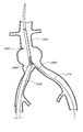
- FIG. 1 is a schematic representation of a bifurcated vascular prosthesis in accordance with the present invention, positioned at the bifurcation between the abdominal aorta and the right and left common iliac arteries.
- FIG. 2 is a cross-sectional view of the implanted graft taken along the lines 2 - 2 of FIG. 1 .
- FIG. 3 is an exploded view of the bifurcated vascular prosthesis in accordance with the present invention, showing a two-part self expandable wire support structure separated from an outer tubular sleeve.
- FIG. 4 is a plan view of formed wire useful for rolling about an axis into an aortic trunk segment and a first iliac branch segment support structure in accordance with the present invention.
- FIG. 5 is a schematic representation of another embodiment of the wire support structure for the bifurcated vascular prosthesis of the present invention, showing a main body support structure and separate branch support structures.
- FIG. 6 is a schematic representation of the three-part wire support structure as in FIG. 5 , illustrating the sliding articulation between the branch supports and the main body support.
- FIG. 7 is a plan view of formed wire useful for rolling about an axis to form a branch support structure in accordance with the three-part support embodiment of the present invention shown in FIG. 5 .
- FIGS. 8A , 8 B and 8 C are enlargements of the apexes delineated by lines A, B and C, respectively, in FIG. 7 .
- FIG. 9A is side elevational cross-section of a bifurcation graft delivery catheter in accordance with the present invention.
- FIG. 9B is a closer view of a portion of FIG. 9A .
- FIG. 9C is similar to the view shown in FIG. 9B with the bifurcation graft delivery catheter shown in a stent exposed configuration.
- FIG. 10 is a cross-section taken along the line 10 - 10 in FIG. 9A .
- FIGS. 11A , B and C are side, top and rear views of a distal tip of the bifurcated delivery catheter shown in FIG. 9A .
- FIG. 12 is a side elevational view of a distal hypotube of the bifurcated delivery catheter shown in FIG. 9A .
- FIGS. 13A and B are top and side views of a peelable cover for restraining a portion of the bifurcated graft.
- FIG. 14 is a schematic representation of a bifurcated graft deployment catheter of the present invention before being inserted into the ipsilateral iliac and the aorta, with the contralateral guidewire positioned within the contralateral iliac
- FIG. 15 is a schematic representation of a bifurcated graft deployment catheter of the present invention, positioned within the ipsilateral iliac and the aorta, with the contralateral guidewire positioned within the contralateral iliac.
- FIG. 16 is a schematic representation as in FIG. 15 , with the outer sheath proximally retracted and the compressed iliac branches of the graft moving into position within the iliac arteries.
- FIG. 17 is a schematic representation as in FIG. 16 , with the outer sheath distally moved as compared to FIG. 16 so as to support the graft within the bifurcation.
- FIG. 18 is a schematic representation as in FIG. 17 , with the main aortic trunk of the graft partially deployed within the aorta.
- FIG. 19 is a schematic representation as in FIG. 18 , with the main aortic trunk of the graft more fully deployed within the aorta.
- FIG. 20 is a schematic representation as in FIG. 19 , with the main aortic trunk of the graft fully deployed within the aorta.
- FIG. 21 is a schematic representation as in FIG. 20 , with both of the contralateral and ipsilateral iliac branches of the graft deployed.
- FIG. 22 is a schematic representation as in FIG. 21 , following removal of the deployment catheter.
- FIG. 23 is a cross-sectional side view of a modified embodiment of a bifurcation graft delivery system with the bifurcation graft delivery catheter shown in a stent exposed configuration.
- FIG. 24 is a cross-sectional view of a portion of a straight tube graft delivery system.
- FIG. 25 is a cross-sectional view of a portion of a modified embodiment of a straight tube graft delivery system.
- FIG. 26A is a close view of portion 26 A of FIG. 9B .
- FIG. 26B is a cross-sectional view taken through line 26 B- 26 B of FIG. 26A .
- FIG. 27A is a modified embodiment of the portion shown in FIG. 26A .
- FIG. 27B is a cross-sectional view taken through line 27 B- 27 B of FIG. 26A .
- FIG. 28A is another modified embodiment of the portion shown in FIG. 26A .
- FIG. 28B is a cross-sectional view taken through line 28 B- 28 B of FIG. 26A
- FIG. 29A is still another modified embodiment of the portion shown in FIG. 26A .
- FIG. 29B is a cross-sectional view taken through line 29 B- 29 B of FIG. 26A .
- FIG. 1 there is disclosed a schematic representation of the abdominal part of the aorta and its principal branches.
- the abdominal aorta 30 is characterized by a right renal artery 32 and left renal artery 34 .
- the large terminal branches of the aorta are the right and left common iliac arteries 36 and 38 .
- Additional vessels e.g., second lumbar, testicular, inferior mesenteric, middle sacral
- An expanded bifurcated endoluminal vascular prosthesis 102 in accordance with one embodiment of the present invention, is illustrated spanning aneurysms 103 , 104 and 105 . It should be appreciated that the illustrated prosthesis 102 and the other prosthesis configurations disclosed herein are only examples of prostheses that are deployable using the devices and methods of the present invention. Moreover, as will be apparent to those of skill in the art in view of the disclosure herein, these devices and methods may be used to deploy essentially any self expandable bifurcated or straight segment prosthesis,
- the illustrated endoluminal vascular prosthesis 102 includes a polymeric sleeve 106 and a tubular wire support 107 , illustrated in situ in FIG. 1 .
- the sleeve 106 and wire support 107 are more readily visualized in the exploded view shown in FIG. 3 .
- the endoluminal prosthesis 102 illustrated and described herein depicts an embodiment in which the polymeric sleeve 106 is situated concentrically outside of the tubular wire support 107 .
- other embodiments may include a sleeve situated instead concentrically inside the wire support or on both of the inside and the outside of the wire support.
- the wire support may be embedded within a polymeric matrix or layer which makes up the sleeve. Regardless of whether the sleeve 106 is inside or outside the wire support 107 , the sleeve may be attached to the wire support by any of a variety of means, as has been previously discussed.
- the tubular wire support 107 comprises a primary component 108 for traversing the aorta and a first iliac, and a branch component 109 for extending into the second iliac.
- the primary component 108 may be formed from a continuous single length of wire, throughout both the aorta trunk portion and the iliac branch portion. See FIGS. 3 and 4 .
- each iliac branch component can be formed separately from the aorta trunk portion. Construction of the graft from a three part cage conveniently facilitates the use of different gauge wire in the different components (e.g. 0.014′′ diameter main trunk and 0.012′′ diameter branch components).
- the wire support 107 is preferably formed in a plurality of discrete segments, connected together and oriented about a common axis.
- Section A corresponds to the aorta trunk portion of the primary component 108 , and includes segments 1 - 5 .
- Segments 6 - 8 correspond to the iliac branch portion of the primary component 108 .
- each of the components of the tubular wire support 107 can be varied considerably in diameter, length, and expansion coefficient, depending upon the intended application.
- the aorta trunk portion (section A) of primary component 108 will have a length within the range of from about 5 cm to about 12 cm, and, typically within the range of from about 9 cm to about 10 cm.
- the unconstrained outside expanded diameter of the section A portion of the primary component 108 will typically be within the range of from about 20 mm to about 40 mm.
- the unconstrained expanded outside diameter of the section A portion of primary component 108 can be constant or substantially constant throughout the length of section A, or can be tapered from a relatively larger diameter at the proximal end to a relatively smaller diameter at the bifurcation.
- the diameter of the distal end of section A will be on the order of no more than about 95% and, preferably, no more than about 85% of the diameter of the proximal end of section A.
- Section C length will generally be within the range of from about 1 cm to about 5 cm, and section C diameter will typically be within the range of from about 10 mm to about 20 mm.
- the wire cage 107 is dividable into a proximal zone 110 , a central zone 111 and a distal zone 112 .
- the wire cage 107 can have a transitional tapered and or stepped diameter within a given zone.
- FIG. 4 there is illustrated a plan view of the single formed wire used for rolling about a longitudinal axis to produce a primary segment 108 having a five segment aorta section and a three segment iliac section.
- the formed wire exhibits distinct segments, each corresponding to an individual tubular segment in the tubular support. Additional details of the wire cage layout and construction can be found in copending U.S. patent application Ser. No. 09/034,689 entitled Endoluminal Vascular Prosthesis, filed Mar. 4, 1998, the disclosure of which is incorporated in its entirety herein by reference.
- Each segment has a repeating pattern of proximal bends 60 connected to corresponding distal bends 62 by wall sections 64 which extend in a generally zig-zag configuration when the segment is radially expanded.
- Each segment is connected to the adjacent segment through a connector 66 , and one or more links 70 (see FIG. 6 ).
- the connector 66 in the illustrated embodiment comprises two wall sections 64 which connect a proximal bend 60 on a first segment with a distal bend 62 on a second, adjacent segment.
- the connector 66 may additionally be provided with a connector bend 68 , which may be used to impart increased radial strength to the graft and/or provide a tie site for a circumferentially extending suture.
- section A is intended for deployment within the aorta whereas section B is intended to be deployed within a first iliac.
- section B will preferably have a smaller expanded diameter than section A. This may be accomplished by providing fewer proximal and distal bends 60 , 62 per segment in section B or in other manners as will be apparent to those of skill in the art in view of the disclosure herein.
- section B has one fewer proximal bend 60 per segment than does each segment in section A. This facilitates wrapping of the wire into a tubular prosthesis cage such as that illustrated in FIG. 3 , so that the iliac branch has a smaller diameter than the aorta branch.
- the second branch is preferably formed from a section of wire in accordance with the general principles discussed above, and in a manner that produces a similarly dimensioned wire cage as that produced by section B.
- the second iliac branch (section C) may be attached at the bifurcation to section A and/or section B in any of a variety of manners, to provide a secure junction therebetween.
- one or two of the proximal bends 60 on section C will be secured to the corresponding distal bends 62 on the distal most segment of section A.
- Attachment may be accomplished such as through the use of a circumferentially threaded suture, through links 70 as has been discussed previously, through soldering or other attachment means.
- the attachment means will be influenced by the desired flexibility of the graft at the bifurcation, which will in turn be influenced by the method of deployment of the vascular graft as will be apparent to those of skill in the art in view of the disclosure herein.
- the tubular wire support comprises a main body, or aortic trunk portion 200 and right 202 and left 204 iliac branch portions.
- Right and left designations correspond to the anatomic designations of right and left common iliac arteries.
- the proximal end 206 of the aortic trunk portion 200 has apexes 211 - 216 adapted for connection with the complementary apexes on the distal ends 208 and 210 of the right 202 and left 204 iliac branch portions, respectively.
- Complementary pairing of apexes is indicated by the shared numbers, wherein the right branch portion apexes are designated by (R) and the left branch portion apexes are designated by (L).
- R right branch portion apexes
- L left branch portion apexes
- Each of the portions may be formed from a continuous single length of wire. See FIG. 7 .
- the central or medial apex 213 in the foreground (anterior) of the aortic trunk portion 200 is linked with 213 (R) on the right iliac portion 202 and 213 (L) on the left iliac portion 204 .
- the central apex 214 in the background (posterior) is linked with 214 (R) on the right iliac portion 202 and 214 (L) on the left iliac portion 204 .
- Each of these linkages has two iliac apexes joined with one aortic branch apex.
- the medial most apexes 218 (R) and (L) of the iliac branch portions 202 and 204 are linked together, without direct connection with the aortic truck portion 200 .
- the medial apexes 213 and 214 function as pivot points about which the right and left iliac branches 202 , 204 can pivot to accommodate unique anatomies.
- the right and left iliac branches 202 , 204 are illustrated at an angle of about 45° to each other, they are articulable through at least an angle of about 90° and preferably at least about 120°.
- the illustrated embodiment allows articulation through about 180° while maintaining patency of the central lumen.
- the apexes 213 and 214 can be displaced proximally from the transverse plane which roughly contains apexes 211 , 212 , 215 and 216 by a minor adjustment to the fixture about which the wire is formed.
- Advancing the pivot point proximally relative to the lateral apexes opens the unbiased angle between the iliac branches 202 and 204 .
- the pivot point is formed by a moveable link between an eye on apex 213 and two apexes 213 R and 213 L folded therethrough.
- the diameter of the eye at apex 213 may be slightly larger than the diameter of the eye on other apexes throughout the graft.
- the diameter of the eye at apex 213 in one embodiment made from 0.014′′ diameter wire is about 0.059′′, compared to a diameter of about 0.020′′ for eyes elsewhere in the graft.
- pivot points 213 , 214 in the illustrated embodiment are on the medial plane, they may be moved laterally such as, for example, to the axis of each of the iliac branches.
- each iliac branch will have an anterior and a posterior pivot link on or about its longitudinal axis, for a total of four unique pivot links at the bifurcation.
- the pivot points can be moved as far as to lateral apexes 211 and 216 .
- Other variations will be apparent to those of skill in the art in view of the disclosure herein.
- the remaining links between the aorta trunk portion 200 and the iliac branches 202 , 204 preferably permit axial compression and expansion.
- at least one and preferably several links lateral to the pivot point in the illustrated embodiment permit axial compression or shortening of the graft to accommodate lateral pivoting of the iliac branch.
- any links medial of the pivot point preferably permit axial elongation to accommodate lateral rotation of the branch. In this manner, the desired range of rotation of the iliac branches may be accomplished with minimal deformation of the wire, and with patency of the graft optimized throughout the angular range of motion.
- the lateral linkages, 211 and 212 for the right iliac, and 215 and 216 for the left iliac may be different from the previously described apex-to-apex linkage configurations.
- the lateral linkages are preferably slideable linkages, wherein a loop formed at the distal end of the iliac apex slidably engages a strut of the corresponding aortic truck portion.
- the loop and strut orientation may be reversed, as will be apparent to those of skill in the art. Interlocking “elbows” without any distinct loop may also be used.
- Such an axially compressible linkage on the lateral margins of the assembled wire support structure allow the iliac branch portions much greater lateral flexibility, thereby facilitating placement in patients who often exhibit a variety of iliac branch asymmetries and different angles of divergence from the aortic trunk.
- FIG. 7 there is illustrated a plan view of a single formed wire used for rolling about a longitudinal axis to produce a four segment straight tubular wire support for an iliac limb.
- the formed wire exhibits distinct segments, each corresponding to an individual tubular segment in the tubular supports 202 or 204 (See FIG. 5 ).
- the distal segment I is adapted to articulate with the aortic trunk portion 200 and the adjacent iliac limb portion.
- the distal segment (I) has two apexes (e.g. corresponding to 211 and 212 on the right iliac portion 202 in FIG. 5 ) which form a loop adapted to slidably engage a strut in the lateral wall of the aortic portion.
- articulating loops (A) are enlarged in FIG. 8A .
- the loops are preferably looped around a strut on the corresponding apex of the proximal aortic segment to provide a sliding linkage.
- the apex 218 is proximally displaced relative to the other four apexes in the distal segment (I).
- Apex 218 (R or L) is designed to link with the complementary 218 apex on the other iliac branch portion (See FIG. 6 ).
- the apex 218 in the illustrated embodiment is formed adjacent or near an intersegment connector 66 , which extends proximally from the distal segment.
- the other apexes on the distal segment (I) of an iliac limb are designed to link with a loop on the corresponding apex of the proximal aortic segment. Because many variations of this linkage are consistent with the present invention the form of the corresponding apexes may vary.
- the apexes (B) form a narrow U-shape, having an inside diameter of about 0.019 inches in an embodiment made from 0.012 inch Conichrome wire (tensile strength 300 ksi minimum) as illustrated in FIG. 8B .
- the U-shaped, elongated axial portion of the apex shown in FIG. 8B permits the apex to be wrapped through and around a corresponding loop apex of the proximal aortic segment.
- the wire support illustrated in FIGS. 5 and 6 comprises a main body support structure formed from one or more lengths of wire and having a proximal end, a distal end and a central lumen extending along a longitudinal axis.
- the wire support also comprises a first branch support structure formed from one or more lengths of wire and having a proximal end, a distal end and a central lumen therethrough.
- the first branch support structure is pivotably connected to the proximal end of the main body support structure.
- the tubular wire support further comprises a second branch support structure formed from one or more lengths of wire and having a proximal end, a distal end and a central lumen extending therethrough.
- the distal end of the second branch support structure is pivotably connected to the proximal end of the main body support structure.
- first and second branch structures may be joined together by a flexible linkage, formed for example between apexes 218 (R) and 218 (L) in FIG. 5 .
- a flexible linkage formed for example between apexes 218 (R) and 218 (L) in FIG. 5 .
- the first and second branch support structures can hinge laterally outward from the longitudinal axis without compromising the volume of the lumen.
- the branches may enjoy a wide range of lateral movement, thereby accommodating a variety of patient and vessel heterogeneity.
- Additional corresponding apexes between the main trunk and each iliac branch may also be connected, or may be free floating within the outer polymeric sleeve.
- Axially compressible lateral linkages discussed above and illustrated in FIG. 6 , may optionally be added.
- proximal apexes (C) of the iliac limb portions are adapted to link with the distal apexes of the next segment.
- These proximal apexes preferably form loops, such as those illustrated in FIG. 8C , wherein the elongated axial portions of the corresponding proximal apex in the adjacent segment can wrap around the loop, thereby providing flexibility of the graft.
- the wire may be made from any of a variety of different alloys and wire diameters or non-round cross-sections, as has been discussed.
- the wire gauge remains substantially constant throughout section A of the primary component 49 and steps down to a second, smaller cross-section throughout section B of primary component 108 .
- a wire diameter of approximately 0.018 inches may be useful in the aorta trunk portion of a graft having five segments each having 2.0 cm length per segment, each segment having six struts intended for use in the aorta, while a smaller diameter such as 0.012 inches might be useful for segments of the graft having 6 struts per segment intended for the iliac artery.
- the wire diameter may be tapered throughout from the proximal to distal ends of the section A and/or section B portions of the primary component 108 .
- the wire diameter may be tapered incremental or stepped down, or stepped up, depending on the radial strength requirements of each particular clinical application.
- the wire has a cross-section of about 0.018 inches in the proximal zone 110 and the wire tapers down regularly or in one or more steps to a diameter of about 0.012 inches in the distal zone 112 of the graft 102 . End point dimensions and rates of taper can be varied widely, within the spirit of the present invention, depending upon the desired clinical performance.
- the diameter of the wire in the iliac branches is no more than about 80% of the diameter of the wire in the aortic trunk. This permits increased flexibility of the graft in the region of the iliac branches, which has been determined by the present inventors to be clinically desirable.
- the collapsed prosthesis in accordance with the present invention has a diameter in the range of about 2 mm to about 10 mm.
- the maximum diameter of the collapsed prosthesis is in the range of about 3 mm to 6 mm (12 to 18 French).
- Some embodiments of the delivery catheter including the prosthesis will be in the range of from 18 to 20 or 21 French; other embodiments will be as low as 19 F, 16 F, 14 F, or smaller.
- the expanded endoluminal vascular prosthesis has radially self-expanded to a diameter anywhere in the range of about 20 to 40 mm, corresponding to expansion ratios of about 1:2 to 1:20.
- the expansion ratios range from about 1:4 to 1:8, more preferably from about 1:4 to 1:6.
- a deployment catheter 320 for deploying a self expandable bifurcation graft such as the one described above and having certain features and aspects according to the present invention will now be described with initial reference to FIGS. 9A-9C .
- the deployment catheter 320 comprises an elongate flexible multicomponent tubular body 322 having a proximal end 324 and a distal end 326 .
- the tubular body 322 and other components of this catheter 320 can be manufactured in accordance with any of a variety of techniques well known in the catheter manufacturing field. Suitable materials and dimensions can be readily selected taking into account the natural anatomical dimensions in the iliacs and aorta, together with the dimensions dictated by the desired percutaneous access site.
- the elongate flexible tubular body 322 comprises an outer sheath 328 , which is axially movably positioned upon a central tubular core 330 .
- the outer sheath 328 comprises extruded PTFE and/or PEEK, having an outside diameter of about 0.280′′ and an inside diameter of about 0.250′′.
- the outer sheath 328 preferably has an axial length within the range of from about 40′′ to about 55′′, and, in one embodiment of the catheter 320 having an overall length of 110 cm, the axial length of the outer sheath 328 is about 52′′.
- the outer sheath 328 is provided at its proximal end with a manifold 332 , having a hemostatic valve 334 thereon and access ports such as for the infusion of drugs or contrast media as will be understood by those of skill in the art.
- the central core 330 defines, in part, a central guidewire lumen 336 , which may in an over the wire construction extend throughout the length of catheter 320 .
- the central lumen 336 has a distal exit port 338 and a proximal access port 340 as will be understood by those of skill in the art.
- the proximal access port 340 is defined by a backend connector 342 , which is attached to the proximal end of the central core 330 .
- the illustrated backend connector 342 preferably also defines a release wire port 344 , the utility of which will be described below.
- the central core 330 is axially movably positioned within but rotationally locked to the outer sheath 328 . As such, the rotational orientation of the central core 330 remains fixed with respect to the rotational orientation of the outer sheath 328 .
- Rotational engagement can be accomplished in any of a variety of ways, normally involving complementary surface structures such as keys or splines on the associated components.
- the central core 330 can be provided with one or two or more radially outwardly extending projections, along a portion or all of its axial length. This projection is slidably received within a radially outwardly extending slot on the interior surface of the outer sheath 328 , or a component secured thereto.
- a radially inwardly extending projection on the outer sheath 328 or an associated component can be received with an axially extending recess on the outer surface of the central core 330 .
- any of a variety of non-round configurations for the central core 330 such as elliptical, oval, triangular, square, polygonal, and the like, can be slidably received within a complementary-shaped aperture on or connected to the outer sheath 328 .
- the central core 330 is provided with a proximal stiffening element 348 (see also FIG. 10 ), which may be in the form of a stainless steel hypotube with a non-round cross-section with two opposing flat sides 350 extending axially along its length. See FIG. 10 .
- the illustrated stiffening element 348 is coupled to the central core 330 by an adhesive, such as, for example, an epoxy 351 .
- a corresponding aperture is provided in a rotational lock 352 provided on the manifold 332 . The resulting assembly enables rotation of the manifold 334 to cause a commensurate rotation of the central core 330 .
- the proximal stiffening element 348 preferably also defines a release wire lumen 354 for guiding a release wire 355 to the release wire port 344 .
- a distal segment of the deployment catheter 320 comprises an elongate flexible tapered distal tip 358 .
- the illustrated distal tip 358 includes a tapered portion 360 , a first cylindrical portion 362 and a recessed portion 364 .
- the distal tip 358 has an axial length of approximately 73 millimeters.
- the tapered portion 360 has an axial length of approximately 48 millimeters
- the first cylindrical portion 362 has an axial length of approximately 15 millimeters
- the recessed portion 364 has an axial length of approximately 10 millimeters.
- the length of the distal tip 358 and the length of the portions 360 , 362 , 364 can be varied depending upon the desired trackability and flexibility characteristics.
- the first cylindrical portion 362 has an outside diameter that is approximately equal to the outside diameter of the outer sheath 328 .
- the tapered portion 360 in turn, preferably tapers from an outside diameter that is approximately equal to the outside diameter of the first cylindrical portion 362 to an outside diameter that is at least about 50% smaller at the distal end thereof.
- the recessed portion 364 is configured to fit within the distal end of the outer sheath 328 .
- the recessed portion 364 preferably defines an annular shoulder 366 , which prevents distal movement of the outer sheath 328 with respect to the distal tip 358 .
- the illustrated recessed portion 364 also includes a second cylindrical portion 368 and a tapered proximal portion 370 .
- the second cylindrical portion 368 is configured to fit within the distal end of the outer sheath 328 when the catheter 320 is in a loaded configuration. See FIG. 9B .
- the second cylindrical portion 368 has an outer diameter that is slightly smaller than the inner diameter of the distal end of the outer sheath 328 .
- the tapered portion 370 has a outer diameter that tapers in the proximal direction and terminates at the central lumen 336 , which extends through the distal tip 358 from the proximal end to the distal end.
- the distal tip preferably also includes a groove 372 , which in the illustrated embodiment extends axially along the second cylindrical portion 368 , through the annual shoulder 366 and the proximal end of the first cylindrical portion 362 . As best seen in FIG. 9B , in a loaded configuration, the groove 372 provides a path for a contralateral guidewire 374 , the utility of which will be described below.
- the distal tip 358 is preferably coupled to the central core 330 .
- the distal tip 358 is coupled to the central core 30 through a distal hypotube 376 , which is best seen in FIG. 12 .
- the distal hypotube 376 may comprise a solid wall such as stainless steel, or a more flexible wall such as a braided polymide tubing.
- the polyimide tubing has an inside diameter of about 0.059′′ and an outside diameter that is slight smaller than the diameter of the central lumen 336 at a proximal end 378 of the distal tip 358 and a distal end 380 of the central core 330 . See FIG. 9B .
- An internal braid is may be made from 0.0015′′ stainless steel 304 wire at a pic count of about 50 braids per inch, such as may be obtained from Phelps Dodge (GA) or H.V. Technologies (GA).
- the use of flexible tubing such as spiral cut layers or woven or braided tubing in place of conventional stainless steel or other metal hypotubing increases the lateral flexibility of the assembled device, which facilitates the placement and deployment steps.
- a distal end 382 of the hypotube 376 is frictionally fitted within the proximal end 378 of the distal tip 358 .
- the distal end 382 is may be provided with a one or more ridges or grooves 383 .
- a proximal end 384 of the distal hypotube 376 is frictionally fitted within the distal end 380 of the central core 330 .
- the proximal end 384 of the distal hypotube 376 may also be provided with one or more ridges or grooves 383 .
- distal hypotube 376 can be connected to distal tip 358 and/or the central core 330 by thermal bonding, adhesive bonding, and/or any of a variety of other securing techniques known in the art which can also be used in addition to the frictional fit described above.
- a junction 386 is formed between a distal end 388 of the outer sheath 328 and the distal tip 358 .
- proximal retraction of the outer sheath 328 with respect to the central core 330 will expose a bifurcated endoluminal graft 390 , as will be discussed in more detail below.
- the bifurcated endoluminal graft 390 is illustrated in an exposed configuration.
- the graft 390 comprises aortic trunk portion 392 , a proximal ipsilateral iliac branch 394 , and a proximal contralateral iliac branch 396 .
- the graft 390 is contained within the outer tubular sheath 328 between the proximal end of the distal tip 358 and the distal end 380 of the central core 330 .
- Proximal movement of the graft 390 is prevented by a proximal stop 398 , which is axially immovably connected to the distal hypotube 376 . See also FIG. 12 .
- the function of the proximal stop 398 can be accomplished through any of a variety of structures as will be apparent to those of skill in the art in view of the disclosure herein.
- the peelable sheath 400 comprises a tubular body 402 having a proximal end 404 and a distal end 406 .
- the peelable sheath 400 is secured to the aortic trunk release wire 355 .
- the aortic trunk release wire 355 in the illustrated embodiment, is secured by way of a joint 410 to the proximal end 404 of the peelable sheath 400 .
- the release wire 355 extends through the catheter 320 between the outer sheath 328 and the inner core 330 and the release wire port lumen 354 exiting the catheter 320 at the release wire port 344 .
- the proximal end 404 of the peelable sheath 100 is provided with a leader 412 of sheath material to facilitate positioning the joint 410 , as will be explained below.
- the peelable sheath 400 is preferably also provided with a peel start point 414 such as a slit, perforation, V-shaped cut, or otherwise as will be apparent to those of skill in the art in view of the disclosure herein.
- the peelable sheath 400 preferably further includes a perforation line 416 , crease, recess or other tear facilitating modification extending axially there along to facilitate predictable tearing of the material.
- the perforation line 416 comprises a series of slits that are about 2.0 millimeters long and separated by a distance of about 1.5 millimeters.
- the peelable sheath 400 may be made from any of a variety of thin, tearable materials as will be apparent to those of skill in the art in view of the disclosure herein.
- the material exhibits sufficient strength that it will restrain the self expandable aortic trunk portion 392 while at the same time maintaining a low cross sectional profile and also permitting tearing to occur with a minimal amount of traction required on the release wire 355 .
- the peelable sheath 400 comprises a PTFE tube having a wall thickness of about 0.012′′, an outside diameter of about 0.218′′ and a length from the peel start point 414 to the distal end 406 of about 10.0 cm.
- the overall length from the joint 410 to the distal end 406 is about 17.0 cm.
- Other thin wall tearable materials may also be used, such as PET, HDPE, or PE.
- the iliac branches 394 and 396 will also remain compressed within a first (ipsilateral) tubular sheath 411 and a second (contralateral) tubular sheath 412 .
- the first tubular sheath 411 is configured to restrain the ipsilateral branch 394 of the graft 390 in the constrained configuration.
- the first tubular sheath 411 is adapted to be axially proximally removed from the ipsilateral branch 394 , thereby permitting the branch to expand to its implanted configuration.
- the first tubular sheath 411 comprises a thin walled PTFE extrusion having an outside diameter of about 0.215′′ and an axial length of about 7.5 cm.
- a proximal end 414 of the tubular sheath 411 is necked down such as by heat shrinking to secure the first tubular sheath 411 to the distal hypotube 376 .
- proximal withdrawal of the distal hypotube 376 will proximally advance the first tubular sheath 411 relative to the graft 390 , thereby deploying the self expandable ipsilateral branch 394 of the graft 390 .
- the second tubular sheath 412 is secured to the contralateral guidewire 374 , which extends outside the catheter 320 at a point 416 (see FIG. 9B ), such as may be conveniently provided at the junction 386 between the outer tubular sheath 328 and the distal tip 358 .
- the contralateral guidewire 374 extends through the groove 372 provided in the distal tip 358 and described above.
- the second tubular sheath 412 is adapted to restrain the contralateral branch 396 of the graft 390 in the reduced profile.
- the second tubular sheath 412 has an outside diameter of about 0.215′′ and an axial length of about 7.5 cm. In the loaded configuration ( FIG. 9B ), the second tubular sheath 412 can have a significantly smaller cross-section than the first tubular sheath 411 , due to the presence of the hypotube 376 within the ipsilateral branch 394 .
- the second tubular sheath 412 is secured at its proximal end to the contralateral guidewire 374 .
- This may be accomplished through any of a variety of securing techniques, such as heat shrinking, adhesives, mechanical interfit and the like.
- the contralateral guidewire 374 is provided with one or more knots or other diameter enlarging structures to provide an interference fit with the proximal end of the second tubular sheath 412 , and the proximal end of the second tubular sheath 412 is heat shrunk and/or bonded in the area of the knot to provide a secure connection.
- the same attachment structure can be used for the peelable sheath 400 as well.
- the contralateral guidewire 374 and release wire 355 can comprise any of a variety of structures, including polymeric monofilament materials, braided or woven materials, metal ribbon or wire, or conventional guidewires as are well known in the art.
- the free end of the contralateral guidewire 374 is percutaneously inserted into the arterial system, such as at a first puncture in a femoral artery.
- the contralateral guidewire 374 is advanced through the corresponding iliac towards the aorta, and crossed over into the contralateral iliac in accordance with cross over techniques, which are well known in the art.
- the contralateral guidewire 374 is then advanced distally down the contralateral iliac where it exits the body at a second percutaneous puncture site.
- the catheter 320 is thereafter percutaneously inserted into the first puncture, and advanced along a guidewire (e.g. 0 . 035 inch) through the ipsilateral iliac and into the aorta.
- a guidewire e.g. 0 . 035 inch
- slack produced in the contralateral guidewire 374 is taken up by proximally withdrawing the contralateral guidewire 374 from the second percutaneous access site.
- the catheter 320 is positioned in the manner generally illustrated in FIG. 15 . Referring to FIG.
- the outer sheath 328 is proximally withdrawn while generally maintaining the axial position of the overall deployment catheter 320 , thereby exposing the aortic trunk 392 and releasing the first and second iliac branches 394 , 396 of the graft 390 .
- the outer sheath 328 can be distally advanced and contralateral guidewire 374 withdraw so as to position the iliac position the branches 394 , 396 of the graft 390 within the iliac arteries as illustrated.
- the outer sheath 328 also provides support for the ispsilateral branch 394 .
- proximal traction is applied to the aortic trunk release wire 355 .
- the distal end 388 of the outer sheath 328 provides a fulcrum for minimizing injury to the adjacent tissue as proximal traction is applied to the aortic trunk release wire 355 .
- Proximal retraction of the release wire 355 pulls the peelable sheath 400 down into the outer sheath 328 . As shown in FIG. 19 , retraction of the release wire 355 pulls the peelable sheath 400 proximally along the aortic trunk 392 such that the aortic trunk 392 is released from the distal end first. Further proximal retraction of the release wire 410 causes the peelable sheath 400 to tear or split distally thereby permitting complete retraction of the peelable sheath 400 from the aortic trunk 392 as illustrated in FIG. 20 .
- the contralateral guidewire 374 is thereafter proximally withdrawn, thereby by proximally withdrawing the second sheath 412 from the contralateral iliac branch 396 of the graft 390 . See FIG. 21 .
- the contralateral branch 396 of the graft 390 thereafter self expands to fit within the contralateral iliac artery.
- the guidewire 374 and sheath 412 may thereafter be proximally withdrawn and removed from the patient, by way of the second percutaneous access site.
- the outer sheath 328 may be proximally withdrawn to expose the ipsilateral branch 394 of the graft 390 .
- a central lumen through the aortic trunk 392 is sufficiently large to permit proximal retraction of the distal tip 358 through the deployed graft 390 .
- the inner core 330 may be proximally withdrawn to release the ipsilateral branch 394 from the first tubular sheath 411 .
- the central lumen through the aortic trunk 392 and ipsilateral branch 394 is sufficiently large to permit complete proximal retraction of the deployment catheter 320 through the graft 390 .
- the graft 390 is now fully deployed and the deployment catheter 230 may thereafter be proximally withdrawn from the patient by way of the first percutaneous access site.
- the ipsilateral branch 394 is compressed within a second peelable sheath 420 , which preferably is configured in a manner similar to the peelable sheath 410 described above.
- the second peelable sheath 420 is secured to an ipsilateral branch release wire 422 , which as with the aortic trunk release wire 410 can extend proximally through the catheter 320 between the outer sheath 328 and the inner core 330 .
- the ipsilateral branch release wire 422 can exit the catheter 320 through the release wire port 344 (see FIG. 9A ).
- a second release port can be provided.
- the ipsilateral branch 394 is released by proximally withdrawing the ipsilateral branch release wire 422 after the aortic trunk 392 and the contralateral branch 396 of the graft 390 have been released as described above.
- the second peelable sheath 420 is preferably not secured to the inner core 330 .
- releasing the ipsilateral branch 394 does not require proximal movement of the inner core 330 .
- the distal end 374 of the outer sheath 328 can be used to provide a fulcrum for minimizing injury to the adjacent tissue as proximal traction is applied to the release wire 422 .
- a deployment catheter 432 is configured in a manner substantially similar to the catheter 320 described above. As such, like numbers are used to refer to parts similar to those of FIGS. 9A-C .
- the illustrated catheter 432 includes an outer sheath 328 , inner core 330 and a distal tip 358 .
- the inner core 330 is connected to a distal tip 358 through a hypotube 376 , which includes a proximal stop 398 for preventing proximal movement of the graft 430 on the hypotube 376 .
- the graft 430 is positioned on the hypotube 376 . In the loaded configuration (not shown), the outer sheath 328 covers the graft 430 .
- the graft 430 is compressed within a peelable sheath 442 , which preferably is configured in a manner similar to the peelable sheath 410 described above.
- the peelable sheath 442 is secured to a release wire 444 through a joint 446 .
- the release wire 444 preferably extends through the catheter 432 between the outer sheath 328 and the inner core 330 .
- the catheter 432 is percutanously inserted into a first puncture in the femoral artery and advanced along a guide wire through the ipsilateral iliac and into the aorta.
- the outer sheath 328 can proximally withdrawn while maintaining the general axial position of the catheter 432 , thereby exposing the graft 430 .
- the graft 430 is released by proximally withdrawing the release wire 444 .
- the central lumen through the graft 430 is sufficiently large to permit complete proximal retraction of the distal tip 438 .
- the catheter 432 may thereafter be proximally withdrawn from the patient by way of the first access site.
- FIG. 25 another modified embodiment of a technique for deploying a self expandable straight tube graft 430 is illustrated.
- the straight tube graft 430 is compressed with a distal peelable sheath 450 and a proximal peelable sheath 452 , which are configured in a manner similar to the peelable sheaths described above.
- the distal peelable sheath 450 is attached to a distal release wire 454 through a junction 456 and in a similar manner the proximal peelable sheath 452 is attached to a proximal release wire 458 through a junction 460 .
- the outer sheath 328 is proximally withdrawn while maintaining the general axial position of the catheter 432 , thereby exposing the graft 430 .
- a device proximal (anatomically inferior) portion 462 of the graft 130 is then released by proximally withdrawing the proximal release wire 458 .
- the distal portion 464 of the graft is released by proximally withdrawing the distal release wire 454 .
- the distal portion 464 is released after the proximal portion 462 so as to prevent a “sail” effect in the thoracic area due to the high pressure, although release can be accomplished in the reverse order.
- the central lumen through the graft is sufficiently large to permit complete proximal retraction of the distal tip 358 .
- the catheter 432 may thereafter be proximally withdrawn from the patient by way of the first access site.
- the forgoing two step deployment structure can also be utilized on the main aorta portion of a bifurcation graft, if deployment anatomically distal to proximal is preferred over the previously disclosed anatomically proximal to distal. See, e.g., FIGS. 17-19 .
- the catheter 320 , 432 is transluminally advanced along the guidewire through the ipsilateral iliac and into the aorta, it is advantageous for the surgeon to be able to visualize the position of the distal end 388 of the outer sheath 328 so as to be able to more accurately place the graft within the patient.
- Catheters may be conventionally formed from extruded PTFE and/or PEEK, which are transparent under fluoroscopic visualization.
- the distal end 388 of the outer sheath 329 preferably includes a band 500 of any of a variety of radio opaque (“RO”) materials that are well known in the art as shown in FIGS. 26A and 26B .
- RO radio opaque
- the distal end 388 of the outer catheter 328 is provided with a groove 352 , in which the band 500 is positioned.
- the distal end 388 can be formed without the groove 352 and the band 500 can be bonded directly around the outer sheath 328 .
- FIGS. 27A and 27B illustrate another embodiment for providing RO material on the catheter.
- RO fixtures or staples 354 are inserted through the outer sheath 328 at the distal end 388 .
- FIGS. 28A and 28B illustrate yet another embodiment for providing RO material on the catheter.
- the distal end 388 of the outer sheath 328 includes a band 556 of RO material that is positioned on the sheath 328 or within a groove 558 .
- the distal end 388 of the outer sheath 328 is inverted proximally over the band 556 so as to cover the outer surface of the band.
- the outer sheath 328 may then be thermally bonded or adhesively bonded to itself proximal the marker bands 556 , to enclose the marker band 556 .
- the band 556 is covered by a layer 560 of shrink wrap tubing, epoxy or similar material.
- RO material can be dispersed in the PEEK or PTFE material, which forms the body of the catheter. In such an embodiment, the density of the RO material is preferably higher at the distal end 388 of the outer sheath 328 .
- the RO material can be attached to or dispersed within the distal tip 358 and/or the inner core 330 in a manner similar to that described above.
Abstract
Description
Claims (11)
Priority Applications (1)
| Application Number | Priority Date | Filing Date | Title |
|---|---|---|---|
| US13/269,332 US8568466B2 (en) | 1999-03-11 | 2011-10-07 | Graft deployment system |
Applications Claiming Priority (5)
| Application Number | Priority Date | Filing Date | Title |
|---|---|---|---|
| US09/266,661 US6261316B1 (en) | 1999-03-11 | 1999-03-11 | Single puncture bifurcation graft deployment system |
| US09/795,993 US6663665B2 (en) | 1999-03-11 | 2001-02-28 | Single puncture bifurcation graft deployment system |
| US42966602P | 2002-11-26 | 2002-11-26 | |
| US10/722,367 US8034100B2 (en) | 1999-03-11 | 2003-11-25 | Graft deployment system |
| US13/269,332 US8568466B2 (en) | 1999-03-11 | 2011-10-07 | Graft deployment system |
Related Parent Applications (1)
| Application Number | Title | Priority Date | Filing Date |
|---|---|---|---|
| US10/722,367 Division US8034100B2 (en) | 1999-03-11 | 2003-11-25 | Graft deployment system |
Publications (2)
| Publication Number | Publication Date |
|---|---|
| US20120029610A1 US20120029610A1 (en) | 2012-02-02 |
| US8568466B2 true US8568466B2 (en) | 2013-10-29 |
Family
ID=46300405
Family Applications (2)
| Application Number | Title | Priority Date | Filing Date |
|---|---|---|---|
| US10/722,367 Expired - Fee Related US8034100B2 (en) | 1999-03-11 | 2003-11-25 | Graft deployment system |
| US13/269,332 Expired - Fee Related US8568466B2 (en) | 1999-03-11 | 2011-10-07 | Graft deployment system |
Family Applications Before (1)
| Application Number | Title | Priority Date | Filing Date |
|---|---|---|---|
| US10/722,367 Expired - Fee Related US8034100B2 (en) | 1999-03-11 | 2003-11-25 | Graft deployment system |
Country Status (1)
| Country | Link |
|---|---|
| US (2) | US8034100B2 (en) |
Cited By (4)
| Publication number | Priority date | Publication date | Assignee | Title |
|---|---|---|---|---|
| US9549835B2 (en) | 2011-03-01 | 2017-01-24 | Endologix, Inc. | Catheter system and methods of using same |
| US9907642B2 (en) | 2009-07-27 | 2018-03-06 | Endologix, Inc. | Stent graft |
| US10765504B2 (en) | 2017-12-01 | 2020-09-08 | C. R. Bard, Inc. | Adjustable vascular graft for custom inner diameter reduction and related methods |
| US11129737B2 (en) | 2015-06-30 | 2021-09-28 | Endologix Llc | Locking assembly for coupling guidewire to delivery system |
Families Citing this family (30)
| Publication number | Priority date | Publication date | Assignee | Title |
|---|---|---|---|---|
| US6261316B1 (en) | 1999-03-11 | 2001-07-17 | Endologix, Inc. | Single puncture bifurcation graft deployment system |
| AU2002230661A1 (en) * | 2000-11-15 | 2002-05-27 | Endologix, Inc. | Implantable vascular graft |
| US7147661B2 (en) | 2001-12-20 | 2006-12-12 | Boston Scientific Santa Rosa Corp. | Radially expandable stent |
| US8377110B2 (en) * | 2004-04-08 | 2013-02-19 | Endologix, Inc. | Endolumenal vascular prosthesis with neointima inhibiting polymeric sleeve |
| US7699883B2 (en) * | 2004-10-25 | 2010-04-20 | Myles Douglas | Vascular graft and deployment system |
| US9757260B2 (en) * | 2006-03-30 | 2017-09-12 | Medtronic Vascular, Inc. | Prosthesis with guide lumen |
| US7722665B2 (en) * | 2006-07-07 | 2010-05-25 | Graft Technologies, Inc. | System and method for providing a graft in a vascular environment |
| US20080071343A1 (en) * | 2006-09-15 | 2008-03-20 | Kevin John Mayberry | Multi-segmented graft deployment system |
| US8523931B2 (en) | 2007-01-12 | 2013-09-03 | Endologix, Inc. | Dual concentric guidewire and methods of bifurcated graft deployment |
| US8221494B2 (en) | 2008-02-22 | 2012-07-17 | Endologix, Inc. | Apparatus and method of placement of a graft or graft system |
| US8236040B2 (en) | 2008-04-11 | 2012-08-07 | Endologix, Inc. | Bifurcated graft deployment systems and methods |
| JP5134729B2 (en) | 2008-07-01 | 2013-01-30 | エンドロジックス、インク | Catheter system |
| EP2429452B1 (en) | 2009-04-28 | 2020-01-15 | Endologix, Inc. | Endoluminal prosthesis system |
| US10772717B2 (en) | 2009-05-01 | 2020-09-15 | Endologix, Inc. | Percutaneous method and device to treat dissections |
| US9579103B2 (en) | 2009-05-01 | 2017-02-28 | Endologix, Inc. | Percutaneous method and device to treat dissections |
| US8491646B2 (en) | 2009-07-15 | 2013-07-23 | Endologix, Inc. | Stent graft |
| AU2010202487B1 (en) * | 2010-06-15 | 2011-07-28 | Cook Incorporated | Pre-loaded multiport delivery device |
| US20120109279A1 (en) | 2010-11-02 | 2012-05-03 | Endologix, Inc. | Apparatus and method of placement of a graft or graft system |
| WO2012068298A1 (en) | 2010-11-17 | 2012-05-24 | Endologix, Inc. | Devices and methods to treat vascular dissections |
| WO2013074921A2 (en) | 2011-11-17 | 2013-05-23 | Smouse Harry Robinson | Methods and apparatus for treating a type 2 endoleak from within an endoluminal stent graft |
| US9687371B2 (en) * | 2012-02-14 | 2017-06-27 | W. L. Gore & Associates, Inc. | Endoprosthesis having aligned legs for ease of cannulation |
| WO2017015498A1 (en) | 2015-07-22 | 2017-01-26 | Nitinol Devices And Components, Inc. | Graft dimpling to improve crimp profile and reduce delivery forces |
| JP2017051502A (en) * | 2015-09-10 | 2017-03-16 | テルモ株式会社 | Self-expandable stent delivery system |
| GB201615219D0 (en) | 2016-09-07 | 2016-10-19 | Vascutek Ltd And Univ Medical Center Hamburg-Eppendorf (Uke) | Hybrid prosthesis and delivery system |
| GB2554670B (en) * | 2016-09-30 | 2022-01-05 | Vascutek Ltd | A vascular graft |
| GB201707929D0 (en) | 2017-05-17 | 2017-06-28 | Vascutek Ltd | Tubular medical device |
| CN209154121U (en) * | 2017-07-03 | 2019-07-26 | 深圳市科奕顿生物医疗科技有限公司 | A kind of self-inflated bifurcated intraluminal stent |
| GB201715658D0 (en) | 2017-09-27 | 2017-11-08 | Vascutek Ltd | An endoluminal device |
| US11096810B2 (en) | 2017-11-29 | 2021-08-24 | Cook Medical Technologies Llc | Preloaded pusher tip for endografts |
| CN113017952B (en) * | 2021-05-26 | 2021-10-08 | 上海微创心脉医疗科技(集团)股份有限公司 | Branch sheath and delivery system |
Citations (41)
| Publication number | Priority date | Publication date | Assignee | Title |
|---|---|---|---|---|
| US4402685A (en) * | 1979-06-30 | 1983-09-06 | Intermedicat Gmbh | Dividable catheter |
| US4617932A (en) * | 1984-04-25 | 1986-10-21 | Elliot Kornberg | Device and method for performing an intraluminal abdominal aortic aneurysm repair |
| US4728328A (en) * | 1984-10-19 | 1988-03-01 | Research Corporation | Cuffed tubular organic prostheses |
| US4747833A (en) * | 1985-10-28 | 1988-05-31 | Terumo Kabushiki Kaisha | Medical instrument-guiding tube and assembly comprising the same |
| US4781690A (en) * | 1986-03-20 | 1988-11-01 | Terumo Kabushiki Kaisha | Guiding tube for medical instruments |
| US4874374A (en) * | 1987-04-08 | 1989-10-17 | Terumo Kabushiki Kaisha | Medical tool introduction cannula and method of manufacturing the same |
| US4888000A (en) * | 1987-06-04 | 1989-12-19 | Femcare Limited | Apparatus for the insertion of catheters |
| US4994071A (en) * | 1989-05-22 | 1991-02-19 | Cordis Corporation | Bifurcating stent apparatus and method |
| US5026377A (en) * | 1989-07-13 | 1991-06-25 | American Medical Systems, Inc. | Stent placement instrument and method |
| US5104388A (en) * | 1990-05-08 | 1992-04-14 | Fbk International Corporation | Membrane splittable tubing |
| US5122154A (en) * | 1990-08-15 | 1992-06-16 | Rhodes Valentine J | Endovascular bypass graft |
| US5158545A (en) * | 1991-05-02 | 1992-10-27 | Brigham And Women's Hospital | Diameter expansion cannula |
| US5167634A (en) * | 1991-08-22 | 1992-12-01 | Datascope Investment Corp. | Peelable sheath with hub connector |
| US5242399A (en) * | 1990-04-25 | 1993-09-07 | Advanced Cardiovascular Systems, Inc. | Method and system for stent delivery |
| US5246452A (en) * | 1992-04-13 | 1993-09-21 | Impra, Inc. | Vascular graft with removable sheath |
| US5522882A (en) * | 1994-10-21 | 1996-06-04 | Impra, Inc. | Method and apparatus for balloon expandable stent-graft delivery |
| US5545209A (en) * | 1993-09-30 | 1996-08-13 | Texas Petrodet, Inc. | Controlled deployment of a medical device |
| US5571135A (en) * | 1993-10-22 | 1996-11-05 | Scimed Life Systems Inc. | Stent delivery apparatus and method |
| US5575817A (en) * | 1994-08-19 | 1996-11-19 | Martin; Eric C. | Aorto femoral bifurcation graft and method of implantation |
| US5591228A (en) * | 1995-05-09 | 1997-01-07 | Edoga; John K. | Methods for treating abdominal aortic aneurysms |
| US5591226A (en) * | 1995-01-23 | 1997-01-07 | Schneider (Usa) Inc. | Percutaneous stent-graft and method for delivery thereof |
| US5607445A (en) * | 1992-06-18 | 1997-03-04 | American Biomed, Inc. | Stent for supporting a blood vessel |
| US5647857A (en) * | 1995-03-16 | 1997-07-15 | Endotex Interventional Systems, Inc. | Protective intraluminal sheath |
| US5669924A (en) * | 1995-10-26 | 1997-09-23 | Shaknovich; Alexander | Y-shuttle stent assembly for bifurcating vessels and method of using the same |
| US5720735A (en) * | 1997-02-12 | 1998-02-24 | Dorros; Gerald | Bifurcated endovascular catheter |
| US5733267A (en) * | 1995-04-05 | 1998-03-31 | Scimed Life Systems, Inc. | Pull back stent delivery system |
| US5741325A (en) * | 1993-10-01 | 1998-04-21 | Emory University | Self-expanding intraluminal composite prosthesis |
| US5755771A (en) * | 1994-11-03 | 1998-05-26 | Divysio Solutions Ulc | Expandable stent and method of delivery of same |
| US5769885A (en) * | 1991-04-11 | 1998-06-23 | Endovascular Technologies, Inc. | Bifurcated multicapsule intraluminal grafting system and method |
| US5851228A (en) * | 1995-06-01 | 1998-12-22 | Meadox Medicals, Inc. | Implantable intraluminal prosthesis |
| US6030415A (en) * | 1997-01-29 | 2000-02-29 | Endovascular Technologies, Inc. | Bell-bottom modular stent-graft |
| US6086611A (en) * | 1997-09-25 | 2000-07-11 | Ave Connaught | Bifurcated stent |
| US6143016A (en) * | 1997-04-21 | 2000-11-07 | Advanced Cardiovascular Systems, Inc. | Sheath and method of use for a stent delivery system |
| US6210422B1 (en) * | 1997-02-20 | 2001-04-03 | Endologix, Inc. | Bifurcated vascular graft deployment device |
| US6224609B1 (en) * | 1998-03-16 | 2001-05-01 | Teramed Inc. | Bifurcated prosthetic graft |
| US6261316B1 (en) * | 1999-03-11 | 2001-07-17 | Endologix, Inc. | Single puncture bifurcation graft deployment system |
| US6447540B1 (en) * | 1996-11-15 | 2002-09-10 | Cook Incorporated | Stent deployment device including splittable sleeve containing the stent |
| US6500202B1 (en) * | 1998-12-11 | 2002-12-31 | Endologix, Inc. | Bifurcation graft deployment catheter |
| US6533811B1 (en) * | 1993-07-08 | 2003-03-18 | Medtronic, Inc. | Internal graft prosthesis and delivery system |
| US6827731B2 (en) * | 2001-01-22 | 2004-12-07 | Gore Enterprise Holdings, Inc. | Deployment system for intraluminal devices |
| US6939327B2 (en) * | 2002-05-07 | 2005-09-06 | Cardiac Pacemakers, Inc. | Peel-away sheath |
Family Cites Families (378)
| Publication number | Priority date | Publication date | Assignee | Title |
|---|---|---|---|---|
| US2127903A (en) | 1936-05-05 | 1938-08-23 | Davis & Geck Inc | Tube for surgical purposes and method of preparing and using the same |
| US2437542A (en) | 1944-05-05 | 1948-03-09 | American Catheter Corp | Catheter-type instrument |
| US2845959A (en) | 1956-03-26 | 1958-08-05 | John B Sidebotham | Bifurcated textile tubes and method of weaving the same |
| US2990605A (en) | 1957-01-30 | 1961-07-04 | Demsyk Paul | Method of forming artificial vascular members |
| US3096560A (en) | 1958-11-21 | 1963-07-09 | William J Liebig | Process for synthetic vascular implants |
| US3029819A (en) | 1959-07-30 | 1962-04-17 | J L Mcatee | Artery graft and method of producing artery grafts |
| US3805301A (en) | 1972-07-28 | 1974-04-23 | Meadox Medicals Inc | Tubular grafts having indicia thereon |
| DE2760437C2 (en) | 1976-04-05 | 1990-03-22 | Agence Nationale De Valorisation De La Recherche (Anvar), Paris, Fr | |
| US4503568A (en) | 1981-11-25 | 1985-03-12 | New England Deaconess Hospital | Small diameter vascular bypass and method |
| US4501263A (en) | 1982-03-31 | 1985-02-26 | Harbuck Stanley C | Method for reducing hypertension of a liver |
| US4592754A (en) | 1983-09-09 | 1986-06-03 | Gupte Pradeep M | Surgical prosthetic vessel graft and catheter combination and method |
| US5693083A (en) | 1983-12-09 | 1997-12-02 | Endovascular Technologies, Inc. | Thoracic graft and delivery catheter |
| US5104399A (en) | 1986-12-10 | 1992-04-14 | Endovascular Technologies, Inc. | Artificial graft and implantation method |
| US6221102B1 (en) | 1983-12-09 | 2001-04-24 | Endovascular Technologies, Inc. | Intraluminal grafting system |
| US5669936A (en) | 1983-12-09 | 1997-09-23 | Endovascular Technologies, Inc. | Endovascular grafting system and method for use therewith |
| US5275622A (en) | 1983-12-09 | 1994-01-04 | Harrison Medical Technologies, Inc. | Endovascular grafting apparatus, system and method and devices for use therewith |
| US5108424A (en) | 1984-01-30 | 1992-04-28 | Meadox Medicals, Inc. | Collagen-impregnated dacron graft |
| US4580568A (en) | 1984-10-01 | 1986-04-08 | Cook, Incorporated | Percutaneous endovascular stent and method for insertion thereof |
| DE3640745A1 (en) | 1985-11-30 | 1987-06-04 | Ernst Peter Prof Dr M Strecker | Catheter for producing or extending connections to or between body cavities |
| US4878906A (en) | 1986-03-25 | 1989-11-07 | Servetus Partnership | Endoprosthesis for repairing a damaged vessel |
| US4756307A (en) | 1987-02-09 | 1988-07-12 | Zimmer, Inc. | Nail device |
| US4800882A (en) | 1987-03-13 | 1989-01-31 | Cook Incorporated | Endovascular stent and delivery system |
| US4907336A (en) | 1987-03-13 | 1990-03-13 | Cook Incorporated | Method of making an endovascular stent and delivery system |
| IT1210722B (en) | 1987-05-11 | 1989-09-20 | Sorin Biomedica Spa | DEVICES FOR THE CONDITIONING OF BLOOD FLOWS |
| US4816028A (en) | 1987-07-01 | 1989-03-28 | Indu Kapadia | Woven vascular graft |
| US5133732A (en) | 1987-10-19 | 1992-07-28 | Medtronic, Inc. | Intravascular stent |
| US4840940A (en) | 1987-10-21 | 1989-06-20 | Sottiurai Vikrom S | Method for reducing the occurrence of distal anastomotic intimal hyperplasia using fractionated heparin |
| JPH0784524B2 (en) | 1987-12-24 | 1995-09-13 | 東ソー株式会社 | Method for producing aromatic sulfide amide polymer |
| US5019090A (en) | 1988-09-01 | 1991-05-28 | Corvita Corporation | Radially expandable endoprosthesis and the like |
| US4981478A (en) | 1988-09-06 | 1991-01-01 | Advanced Cardiovascular Systems | Composite vascular catheter |
| US4856516A (en) | 1989-01-09 | 1989-08-15 | Cordis Corporation | Endovascular stent apparatus and method |
| CH678393A5 (en) | 1989-01-26 | 1991-09-13 | Ulrich Prof Dr Med Sigwart | |
| US5078726A (en) | 1989-02-01 | 1992-01-07 | Kreamer Jeffry W | Graft stent and method of repairing blood vessels |
| US5178634A (en) | 1989-03-31 | 1993-01-12 | Wilson Ramos Martinez | Aortic valved tubes for human implants |
| US5662701A (en) | 1989-08-18 | 1997-09-02 | Endovascular Instruments, Inc. | Anti-stenotic method and product for occluded and partially occluded arteries |
| US5571169A (en) | 1993-06-07 | 1996-11-05 | Endovascular Instruments, Inc. | Anti-stenotic method and product for occluded and partially occluded arteries |
| US5035706A (en) | 1989-10-17 | 1991-07-30 | Cook Incorporated | Percutaneous stent and method for retrieval thereof |
| US5123917A (en) | 1990-04-27 | 1992-06-23 | Lee Peter Y | Expandable intraluminal vascular graft |
| US5116349A (en) | 1990-05-23 | 1992-05-26 | United States Surgical Corporation | Surgical fastener apparatus |
| US5360443A (en) | 1990-06-11 | 1994-11-01 | Barone Hector D | Aortic graft for repairing an abdominal aortic aneurysm |
| US5578071A (en) | 1990-06-11 | 1996-11-26 | Parodi; Juan C. | Aortic graft |
| US5156619A (en) | 1990-06-15 | 1992-10-20 | Ehrenfeld William K | Flanged end-to-side vascular graft |
| US5064435A (en) | 1990-06-28 | 1991-11-12 | Schneider (Usa) Inc. | Self-expanding prosthesis having stable axial length |
| DE9116881U1 (en) | 1990-10-09 | 1994-07-07 | Cook Inc | Percutaneous stent |
| JPH0717314Y2 (en) | 1990-10-18 | 1995-04-26 | ソン ホーヨン | Self-expanding intravascular stent |
| CA2060067A1 (en) | 1991-01-28 | 1992-07-29 | Lilip Lau | Stent delivery system |
| US5135536A (en) | 1991-02-05 | 1992-08-04 | Cordis Corporation | Endovascular stent and method |
| CA2202800A1 (en) | 1991-04-11 | 1992-10-12 | Alec A. Piplani | Endovascular graft having bifurcation and apparatus and method for deploying the same |
| US5554118A (en) | 1991-05-24 | 1996-09-10 | Jang; G. David | Universal mode vascular catheter system |
| US5304200A (en) | 1991-05-29 | 1994-04-19 | Cordis Corporation | Welded radially expandable endoprosthesis and the like |
| US5135535A (en) | 1991-06-11 | 1992-08-04 | Advanced Cardiovascular Systems, Inc. | Catheter system with catheter and guidewire exchange |
| US5314472A (en) | 1991-10-01 | 1994-05-24 | Cook Incorporated | Vascular stent |
| US5197976A (en) | 1991-09-16 | 1993-03-30 | Atrium Medical Corporation | Manually separable multi-lumen vascular graft |
| US5443498A (en) | 1991-10-01 | 1995-08-22 | Cook Incorporated | Vascular stent and method of making and implanting a vacsular stent |
| US5464450A (en) | 1991-10-04 | 1995-11-07 | Scimed Lifesystems Inc. | Biodegradable drug delivery vascular stent |
| US5366504A (en) | 1992-05-20 | 1994-11-22 | Boston Scientific Corporation | Tubular medical prosthesis |
| US5282860A (en) | 1991-10-16 | 1994-02-01 | Olympus Optical Co., Ltd. | Stent tube for medical use |
| US5693084A (en) | 1991-10-25 | 1997-12-02 | Cook Incorporated | Expandable transluminal graft prosthesis for repair of aneurysm |
| US5456713A (en) | 1991-10-25 | 1995-10-10 | Cook Incorporated | Expandable transluminal graft prosthesis for repairs of aneurysm and method for implanting |
| US5387235A (en) | 1991-10-25 | 1995-02-07 | Cook Incorporated | Expandable transluminal graft prosthesis for repair of aneurysm |
| US5720776A (en) | 1991-10-25 | 1998-02-24 | Cook Incorporated | Barb and expandable transluminal graft prosthesis for repair of aneurysm |
| EP0539237A1 (en) | 1991-10-25 | 1993-04-28 | Cook Incorporated | Expandable transluminal graft prosthesis for repair of aneurysm and method for implanting |
| US5211658A (en) | 1991-11-05 | 1993-05-18 | New England Deaconess Hospital Corporation | Method and device for performing endovascular repair of aneurysms |
| US5316023A (en) | 1992-01-08 | 1994-05-31 | Expandable Grafts Partnership | Method for bilateral intra-aortic bypass |
| US5507767A (en) | 1992-01-15 | 1996-04-16 | Cook Incorporated | Spiral stent |
| US5405377A (en) | 1992-02-21 | 1995-04-11 | Endotech Ltd. | Intraluminal stent |
| US5683448A (en) | 1992-02-21 | 1997-11-04 | Boston Scientific Technology, Inc. | Intraluminal stent and graft |
| US5282823A (en) | 1992-03-19 | 1994-02-01 | Medtronic, Inc. | Intravascular radially expandable stent |
| US5370683A (en) | 1992-03-25 | 1994-12-06 | Cook Incorporated | Vascular stent |
| US5201757A (en) | 1992-04-03 | 1993-04-13 | Schneider (Usa) Inc. | Medial region deployment of radially self-expanding stents |
| US5263932A (en) | 1992-04-09 | 1993-11-23 | Jang G David | Bailout catheter for fixed wire angioplasty |
| US5354308A (en) | 1992-05-01 | 1994-10-11 | Beth Israel Hospital Association | Metal wire stent |
| US5405378A (en) | 1992-05-20 | 1995-04-11 | Strecker; Ernst P. | Device with a prosthesis implantable in the body of a patient |
| US5507771A (en) | 1992-06-15 | 1996-04-16 | Cook Incorporated | Stent assembly |
| US5496365A (en) | 1992-07-02 | 1996-03-05 | Sgro; Jean-Claude | Autoexpandable vascular endoprosthesis |
| US5643339A (en) | 1992-08-06 | 1997-07-01 | William Cook Europe A/S | Prosthetic device for sustaining a blood-vessel or hollow organ lumen |
| DE59206251D1 (en) | 1992-10-31 | 1996-06-13 | Schneider Europ Ag | Arrangement for implanting self-expanding endoprostheses |
| BE1006440A3 (en) | 1992-12-21 | 1994-08-30 | Dereume Jean Pierre Georges Em | Luminal endoprosthesis AND METHOD OF PREPARATION. |
| US5256141A (en) | 1992-12-22 | 1993-10-26 | Nelson Gencheff | Biological material deployment method and apparatus |
| EP0676936A1 (en) | 1992-12-30 | 1995-10-18 | Schneider (Usa) Inc. | Apparatus for deploying body implantable stents |
| US5843167A (en) | 1993-04-22 | 1998-12-01 | C. R. Bard, Inc. | Method and apparatus for recapture of hooked endoprosthesis |
| AU689094B2 (en) | 1993-04-22 | 1998-03-26 | C.R. Bard Inc. | Non-migrating vascular prosthesis and minimally invasive placement system therefor |
| EP0621015B1 (en) | 1993-04-23 | 1998-03-18 | Schneider (Europe) Ag | Stent with a covering layer of elastic material and method for applying the layer on the stent |
| US5464650A (en) | 1993-04-26 | 1995-11-07 | Medtronic, Inc. | Intravascular stent and method |
| US5643171A (en) | 1993-05-04 | 1997-07-01 | Neocardia, Llc | Method and apparatus for uniform radiation treatment of vascular lumens |
| US5320602A (en) | 1993-05-14 | 1994-06-14 | Wilson-Cook Medical, Inc. | Peel-away endoscopic retrograde cholangio pancreatography catheter and a method for using the same |
| US5425765A (en) | 1993-06-25 | 1995-06-20 | Tiefenbrun; Jonathan | Surgical bypass method |
| US5458615A (en) | 1993-07-06 | 1995-10-17 | Advanced Cardiovascular Systems, Inc. | Stent delivery system |
| CA2125258C (en) | 1993-08-05 | 1998-12-22 | Dinah B Quiachon | Multicapsule intraluminal grafting system and method |
| US6027779A (en) | 1993-08-18 | 2000-02-22 | W. L. Gore & Associates, Inc. | Thin-wall polytetrafluoroethylene tube |
| US5735892A (en) | 1993-08-18 | 1998-04-07 | W. L. Gore & Associates, Inc. | Intraluminal stent graft |
| AU6987594A (en) | 1993-08-18 | 1995-03-14 | W.L. Gore & Associates, Inc. | A tubular intraluminal graft |
| US6159565A (en) | 1993-08-18 | 2000-12-12 | W. L. Gore & Associates, Inc. | Thin-wall intraluminal graft |
| KR970004845Y1 (en) | 1993-09-27 | 1997-05-21 | 주식회사 수호메디테크 | Stent for expanding a lumen |
| WO1995008966A1 (en) | 1993-09-30 | 1995-04-06 | White Geoffrey H | Intraluminal graft |
| EP0659389B1 (en) | 1993-10-20 | 1998-04-22 | Schneider (Europe) Ag | Endoprothese |
| US5639278A (en) | 1993-10-21 | 1997-06-17 | Corvita Corporation | Expandable supportive bifurcated endoluminal grafts |
| US5723004A (en) | 1993-10-21 | 1998-03-03 | Corvita Corporation | Expandable supportive endoluminal grafts |
| US5632772A (en) | 1993-10-21 | 1997-05-27 | Corvita Corporation | Expandable supportive branched endoluminal grafts |
| US5989280A (en) | 1993-10-22 | 1999-11-23 | Scimed Lifesystems, Inc | Stent delivery apparatus and method |
| EP0657147B1 (en) | 1993-11-04 | 1999-08-04 | C.R. Bard, Inc. | Non-migrating vascular prosthesis |
| AU1091095A (en) | 1993-11-08 | 1995-05-29 | Harrison M. Lazarus | Intraluminal vascular graft and method |
| JP2703510B2 (en) | 1993-12-28 | 1998-01-26 | アドヴァンスド カーディオヴァスキュラー システムズ インコーポレーテッド | Expandable stent and method of manufacturing the same |
| US5403341A (en) | 1994-01-24 | 1995-04-04 | Solar; Ronald J. | Parallel flow endovascular stent and deployment apparatus therefore |
| US5549635A (en) | 1994-01-24 | 1996-08-27 | Solar, Rita & Gaterud, Ltd. | Non-deformable self-expanding parallel flow endovascular stent and deployment apparatus therefore |
| CA2160022C (en) | 1994-02-07 | 2005-01-18 | Keiji Igaki | Stent device and stent supplying system |
| US5609627A (en) | 1994-02-09 | 1997-03-11 | Boston Scientific Technology, Inc. | Method for delivering a bifurcated endoluminal prosthesis |
| US6051020A (en) | 1994-02-09 | 2000-04-18 | Boston Scientific Technology, Inc. | Bifurcated endoluminal prosthesis |
| US5507769A (en) | 1994-10-18 | 1996-04-16 | Stentco, Inc. | Method and apparatus for forming an endoluminal bifurcated graft |
| US5443477A (en) | 1994-02-10 | 1995-08-22 | Stentco, Inc. | Apparatus and method for deployment of radially expandable stents by a mechanical linkage |
| US6039749A (en) | 1994-02-10 | 2000-03-21 | Endovascular Systems, Inc. | Method and apparatus for deploying non-circular stents and graftstent complexes |
| US5453090A (en) | 1994-03-01 | 1995-09-26 | Cordis Corporation | Method of stent delivery through an elongate softenable sheath |
| US5653746A (en) | 1994-03-08 | 1997-08-05 | Meadox Medicals, Inc. | Radially expandable tubular prosthesis |
| US5415664A (en) | 1994-03-30 | 1995-05-16 | Corvita Corporation | Method and apparatus for introducing a stent or a stent-graft |
| US5554181A (en) | 1994-05-04 | 1996-09-10 | Regents Of The University Of Minnesota | Stent |
| US5824044A (en) | 1994-05-12 | 1998-10-20 | Endovascular Technologies, Inc. | Bifurcated multicapsule intraluminal grafting system |
| US5456694A (en) | 1994-05-13 | 1995-10-10 | Stentco, Inc. | Device for delivering and deploying intraluminal devices |
| DE4418336A1 (en) | 1994-05-26 | 1995-11-30 | Angiomed Ag | Stent for widening and holding open receptacles |
| US5824041A (en) | 1994-06-08 | 1998-10-20 | Medtronic, Inc. | Apparatus and methods for placement and repositioning of intraluminal prostheses |
| US5683451A (en) | 1994-06-08 | 1997-11-04 | Cardiovascular Concepts, Inc. | Apparatus and methods for deployment release of intraluminal prostheses |
| US6013854A (en) | 1994-06-17 | 2000-01-11 | Terumo Kabushiki Kaisha | Indwelling stent and the method for manufacturing the same |
| US5522881A (en) | 1994-06-28 | 1996-06-04 | Meadox Medicals, Inc. | Implantable tubular prosthesis having integral cuffs |
| US5397355A (en) | 1994-07-19 | 1995-03-14 | Stentco, Inc. | Intraluminal stent |
| US5575816A (en) | 1994-08-12 | 1996-11-19 | Meadox Medicals, Inc. | High strength and high density intraluminal wire stent |
| US5571172A (en) | 1994-08-15 | 1996-11-05 | Origin Medsystems, Inc. | Method and apparatus for endoscopic grafting |
| US5591230A (en) | 1994-09-07 | 1997-01-07 | Global Therapeutics, Inc. | Radially expandable stent |
| US6015429A (en) | 1994-09-08 | 2000-01-18 | Gore Enterprise Holdings, Inc. | Procedures for introducing stents and stent-grafts |
| US5653743A (en) | 1994-09-09 | 1997-08-05 | Martin; Eric C. | Hypogastric artery bifurcation graft and method of implantation |
| US5643748A (en) | 1994-09-14 | 1997-07-01 | Progenitor, Inc. | HU-B1.219, a novel human hematopoietin receptor |
| US5599305A (en) | 1994-10-24 | 1997-02-04 | Cardiovascular Concepts, Inc. | Large-diameter introducer sheath having hemostasis valve and removable steering mechanism |
| CA2175720C (en) | 1996-05-03 | 2011-11-29 | Ian M. Penn | Bifurcated stent and method for the manufacture and delivery of same |
| JP3611578B2 (en) | 1994-11-09 | 2005-01-19 | エンドテックス インターベンショナル システムズ,インコーポレイテッド | Delivery catheter and graft for the treatment of aneurysms |
| AU3783195A (en) | 1994-11-15 | 1996-05-23 | Advanced Cardiovascular Systems Inc. | Intraluminal stent for attaching a graft |
| US5616114A (en) | 1994-12-08 | 1997-04-01 | Neocardia, Llc. | Intravascular radiotherapy employing a liquid-suspended source |
| US5630829A (en) | 1994-12-09 | 1997-05-20 | Intervascular, Inc. | High hoop strength intraluminal stent |
| US5879366A (en) | 1996-12-20 | 1999-03-09 | W.L. Gore & Associates, Inc. | Self-expanding defect closure device and method of making and using |
| NL9500094A (en) | 1995-01-19 | 1996-09-02 | Industrial Res Bv | Y-shaped stent and method of deployment. |
| US5755770A (en) | 1995-01-31 | 1998-05-26 | Boston Scientific Corporatiion | Endovascular aortic graft |
| US5575818A (en) | 1995-02-14 | 1996-11-19 | Corvita Corporation | Endovascular stent with locking ring |
| US5522883A (en) | 1995-02-17 | 1996-06-04 | Meadox Medicals, Inc. | Endoprosthesis stent/graft deployment system |
| CA2213403C (en) | 1995-02-22 | 2007-01-16 | Menlo Care, Inc. | Covered expanding mesh stent |
| US5683449A (en) | 1995-02-24 | 1997-11-04 | Marcade; Jean Paul | Modular bifurcated intraluminal grafts and methods for delivering and assembling same |
| US5681345A (en) | 1995-03-01 | 1997-10-28 | Scimed Life Systems, Inc. | Sleeve carrying stent |
| US6818014B2 (en) | 1995-03-01 | 2004-11-16 | Scimed Life Systems, Inc. | Longitudinally flexible expandable stent |
| US6039755A (en) | 1997-02-05 | 2000-03-21 | Impra, Inc., A Division Of C.R. Bard, Inc. | Radially expandable tubular polytetrafluoroethylene grafts and method of making same |
| US6124523A (en) | 1995-03-10 | 2000-09-26 | Impra, Inc. | Encapsulated stent |
| EP0814729B1 (en) | 1995-03-10 | 2000-08-09 | Impra, Inc. | Endoluminal encapsulated stent and methods of manufacture |
| WO1996028116A1 (en) | 1995-03-10 | 1996-09-19 | Cardiovascular Concepts, Inc. | Tubular endoluminar prosthesis having oblique ends |
| US5591197A (en) | 1995-03-14 | 1997-01-07 | Advanced Cardiovascular Systems, Inc. | Expandable stent forming projecting barbs and method for deploying |
| CA2171896C (en) | 1995-03-17 | 2007-05-15 | Scott C. Anderson | Multi-anchor stent |
| US5643278A (en) | 1995-04-06 | 1997-07-01 | Leocor, Inc. | Stent delivery system |
| EP0740928B1 (en) | 1995-04-12 | 2004-07-07 | Corvita Europe | Self-expanding stent for introducing a medical device in a body cavity and manufacturing process |
| AU4632196A (en) | 1995-04-14 | 1996-10-30 | Schneider (Usa) Inc. | Rolling membrane stent delivery device |
| US5641373A (en) | 1995-04-17 | 1997-06-24 | Baxter International Inc. | Method of manufacturing a radially-enlargeable PTFE tape-reinforced vascular graft |
| US5609628A (en) | 1995-04-20 | 1997-03-11 | Keranen; Victor J. | Intravascular graft and catheter |
| ES2129247T3 (en) | 1995-04-21 | 1999-06-01 | Bard Inc C R | SET OF INTERCONNECTABLE CATHETERS. |
| US5591198A (en) | 1995-04-27 | 1997-01-07 | Medtronic, Inc. | Multiple sinusoidal wave configuration stent |
| FR2733682B1 (en) | 1995-05-04 | 1997-10-31 | Dibie Alain | ENDOPROSTHESIS FOR THE TREATMENT OF STENOSIS ON BIFURCATIONS OF BLOOD VESSELS AND LAYING EQUIPMENT THEREFOR |
| US5746766A (en) | 1995-05-09 | 1998-05-05 | Edoga; John K. | Surgical stent |
| US5662614A (en) | 1995-05-09 | 1997-09-02 | Edoga; John K. | Balloon expandable universal access sheath |
| US5628786A (en) | 1995-05-12 | 1997-05-13 | Impra, Inc. | Radially expandable vascular graft with resistance to longitudinal compression and method of making same |
| WO1996036297A1 (en) | 1995-05-19 | 1996-11-21 | Kanji Inoue | Transplantation instrument, method of bending same and method of transplanting same |
| US6151404A (en) | 1995-06-01 | 2000-11-21 | Medical Media Systems | Anatomical visualization system |
| AU5950696A (en) | 1995-06-05 | 1996-12-24 | Creative Products Resource, Inc. | Dry-cleaning kit for in-dryer use |
| RU2157146C2 (en) | 1995-06-13 | 2000-10-10 | ВИЛЬЯМ КУК Европа, A/S | Device for performing implantation in blood vessels and hollow organs |
| US5676685A (en) | 1995-06-22 | 1997-10-14 | Razavi; Ali | Temporary stent |
| US5766203A (en) | 1995-07-20 | 1998-06-16 | Intelliwire, Inc. | Sheath with expandable distal extremity and balloon catheters and stents for use therewith and method |
| US5562697A (en) | 1995-09-18 | 1996-10-08 | William Cook, Europe A/S | Self-expanding stent assembly and methods for the manufacture thereof |
| US5824037A (en) | 1995-10-03 | 1998-10-20 | Medtronic, Inc. | Modular intraluminal prostheses construction and methods |
| US6193745B1 (en) | 1995-10-03 | 2001-02-27 | Medtronic, Inc. | Modular intraluminal prosteheses construction and methods |
| US6099558A (en) | 1995-10-10 | 2000-08-08 | Edwards Lifesciences Corp. | Intraluminal grafting of a bifuricated artery |
| WO1997014375A1 (en) | 1995-10-20 | 1997-04-24 | Bandula Wijay | Vascular stent |
| US5591195A (en) | 1995-10-30 | 1997-01-07 | Taheri; Syde | Apparatus and method for engrafting a blood vessel |
| US6348066B1 (en) | 1995-11-07 | 2002-02-19 | Corvita Corporation | Modular endoluminal stent-grafts and methods for their use |
| US5628788A (en) | 1995-11-07 | 1997-05-13 | Corvita Corporation | Self-expanding endoluminal stent-graft |
| ES2131253T3 (en) | 1995-11-14 | 1999-07-16 | Schneider Europ Gmbh | DEVICE FOR THE IMPLEMENTATION OF AN ENDOPROTESIS. |
| US5593417A (en) | 1995-11-27 | 1997-01-14 | Rhodes; Valentine J. | Intravascular stent with secure mounting means |
| US5665117A (en) | 1995-11-27 | 1997-09-09 | Rhodes; Valentine J. | Endovascular prosthesis with improved sealing means for aneurysmal arterial disease and method of use |
| US6576009B2 (en) | 1995-12-01 | 2003-06-10 | Medtronic Ave, Inc. | Bifurcated intraluminal prostheses construction and methods |
| US5824040A (en) | 1995-12-01 | 1998-10-20 | Medtronic, Inc. | Endoluminal prostheses and therapies for highly variable body lumens |
| US6042605A (en) | 1995-12-14 | 2000-03-28 | Gore Enterprose Holdings, Inc. | Kink resistant stent-graft |
| EP0866677A4 (en) | 1995-12-14 | 1999-10-27 | Prograft Medical Inc | Stent-graft deployment apparatus and method |
| US5693066A (en) | 1995-12-21 | 1997-12-02 | Medtronic, Inc. | Stent mounting and transfer device and method |
| US5604435A (en) | 1995-12-29 | 1997-02-18 | General Electric Company | Spiral scanning method for monitoring physiological changes |
| DE69732794T2 (en) | 1996-01-05 | 2006-04-06 | Medtronic, Inc., Minneapolis | EXPANDABLE ENDOLUMINARY PROSTHESIS |
| US5690642A (en) | 1996-01-18 | 1997-11-25 | Cook Incorporated | Rapid exchange stent delivery balloon catheter |
| US5800512A (en) | 1996-01-22 | 1998-09-01 | Meadox Medicals, Inc. | PTFE vascular graft |
| AUPN775296A0 (en) | 1996-01-25 | 1996-02-22 | Endogad Research Pty Limited | Directional catheter |
| US6017363A (en) | 1997-09-22 | 2000-01-25 | Cordis Corporation | Bifurcated axially flexible stent |
| AU723785B2 (en) | 1996-02-02 | 2000-09-07 | Transvascular, Inc. | Methods and apparatus for connecting openings formed in adjacent blood vessels or other anatomical structures |
| US5871537A (en) | 1996-02-13 | 1999-02-16 | Scimed Life Systems, Inc. | Endovascular apparatus |
| US5690643A (en) | 1996-02-20 | 1997-11-25 | Leocor, Incorporated | Stent delivery system |
| US5695516A (en) | 1996-02-21 | 1997-12-09 | Iso Stent, Inc. | Longitudinally elongating balloon expandable stent |
| US5810836A (en) | 1996-03-04 | 1998-09-22 | Myocardial Stents, Inc. | Device and method for trans myocardial revascularization (TMR) |
| US5843160A (en) | 1996-04-01 | 1998-12-01 | Rhodes; Valentine J. | Prostheses for aneurysmal and/or occlusive disease at a bifurcation in a vessel, duct, or lumen |
| US5630830A (en) | 1996-04-10 | 1997-05-20 | Medtronic, Inc. | Device and method for mounting stents on delivery systems |
| JP3410922B2 (en) | 1996-04-23 | 2003-05-26 | 株式会社東芝 | Clock control circuit |
| FR2749160B1 (en) | 1996-05-28 | 1999-05-21 | Patrice Bergeron | MODULAR BIFURCED VASCULAR PROSTHESIS |
| US5928279A (en) | 1996-07-03 | 1999-07-27 | Baxter International Inc. | Stented, radially expandable, tubular PTFE grafts |
| GB9614950D0 (en) | 1996-07-16 | 1996-09-04 | Anson Medical Ltd | A ductus stent and delivery catheter |
| US5676697A (en) | 1996-07-29 | 1997-10-14 | Cardiovascular Dynamics, Inc. | Two-piece, bifurcated intraluminal graft for repair of aneurysm |
| US6254628B1 (en) | 1996-12-09 | 2001-07-03 | Micro Therapeutics, Inc. | Intracranial stent |
| US6027508A (en) | 1996-10-03 | 2000-02-22 | Scimed Life Systems, Inc. | Stent retrieval device |
| US6395017B1 (en) | 1996-11-15 | 2002-05-28 | C. R. Bard, Inc. | Endoprosthesis delivery catheter with sequential stage control |
| US5860998A (en) | 1996-11-25 | 1999-01-19 | C. R. Bard, Inc. | Deployment device for tubular expandable prosthesis |
| US6352561B1 (en) | 1996-12-23 | 2002-03-05 | W. L. Gore & Associates | Implant deployment apparatus |
| US6551350B1 (en) | 1996-12-23 | 2003-04-22 | Gore Enterprise Holdings, Inc. | Kink resistant bifurcated prosthesis |
| US5879321A (en) | 1997-01-22 | 1999-03-09 | The University Of Kentucky Research Foundation | Portocaval-right atrial shunt |
| US6203735B1 (en) | 1997-02-03 | 2001-03-20 | Impra, Inc. | Method of making expanded polytetrafluoroethylene products |
| US5827321A (en) | 1997-02-07 | 1998-10-27 | Cornerstone Devices, Inc. | Non-Foreshortening intraluminal prosthesis |
| US6951572B1 (en) | 1997-02-20 | 2005-10-04 | Endologix, Inc. | Bifurcated vascular graft and method and apparatus for deploying same |
| US5893868A (en) | 1997-03-05 | 1999-04-13 | Scimed Life Systems, Inc. | Catheter with removable balloon protector and stent delivery system with removable stent protector |
| US6152944A (en) | 1997-03-05 | 2000-11-28 | Scimed Life Systems, Inc. | Catheter with removable balloon protector and stent delivery system with removable stent protector |
| US5824053A (en) | 1997-03-18 | 1998-10-20 | Endotex Interventional Systems, Inc. | Helical mesh endoprosthesis and methods of use |
| US5868783A (en) | 1997-04-16 | 1999-02-09 | Numed, Inc. | Intravascular stent with limited axial shrinkage |
| US5906641A (en) | 1997-05-27 | 1999-05-25 | Schneider (Usa) Inc | Bifurcated stent graft |
| EP0884029B1 (en) | 1997-06-13 | 2004-12-22 | Gary J. Becker | Expandable intraluminal endoprosthesis |
| US6070589A (en) | 1997-08-01 | 2000-06-06 | Teramed, Inc. | Methods for deploying bypass graft stents |
| US5855599A (en) | 1997-09-02 | 1999-01-05 | Sitek, Inc. | Silicon micro machined occlusion implant |
| US6056722A (en) | 1997-09-18 | 2000-05-02 | Iowa-India Investments Company Limited Of Douglas | Delivery mechanism for balloons, drugs, stents and other physical/mechanical agents and methods of use |
| US6592548B2 (en) | 1997-09-18 | 2003-07-15 | Iowa-India Investments Company Limited Of Douglas | Delivery mechanism for balloons, drugs, stents and other physical/mechanical agents and method of use |
| US6520988B1 (en) | 1997-09-24 | 2003-02-18 | Medtronic Ave, Inc. | Endolumenal prosthesis and method of use in bifurcation regions of body lumens |
| US5893887A (en) | 1997-10-14 | 1999-04-13 | Iowa-India Investments Company Limited | Stent for positioning at junction of bifurcated blood vessel and method of making |
| ES1038606Y (en) | 1997-10-28 | 1999-01-01 | Costilla Garcia Serafin Marcos | FORKED SELF-EXPANDING PROSTHESIS CONVEYOR EQUIPMENT. |
| US5961548A (en) | 1997-11-18 | 1999-10-05 | Shmulewitz; Ascher | Bifurcated two-part graft and methods of implantation |
| AUPP083597A0 (en) | 1997-12-10 | 1998-01-08 | William A Cook Australia Pty Ltd | Endoluminal aortic stents |
| US6475170B1 (en) | 1997-12-30 | 2002-11-05 | Remon Medical Technologies Ltd | Acoustic biosensor for monitoring physiological conditions in a body implantation site |
| US6074398A (en) | 1998-01-13 | 2000-06-13 | Datascope Investment Corp. | Reduced diameter stent/graft deployment catheter |
| EP1656906A1 (en) | 1998-01-26 | 2006-05-17 | Anson Medical Limited | Reinforced graft |
| US6395019B2 (en) | 1998-02-09 | 2002-05-28 | Trivascular, Inc. | Endovascular graft |
| US6395018B1 (en) | 1998-02-09 | 2002-05-28 | Wilfrido R. Castaneda | Endovascular graft and process for bridging a defect in a main vessel near one of more branch vessels |
| US6280467B1 (en) | 1998-02-26 | 2001-08-28 | World Medical Manufacturing Corporation | Delivery system for deployment and endovascular assembly of a multi-stage stented graft |
| US6077296A (en) | 1998-03-04 | 2000-06-20 | Endologix, Inc. | Endoluminal vascular prosthesis |
| US6129756A (en) | 1998-03-16 | 2000-10-10 | Teramed, Inc. | Biluminal endovascular graft system |
| US6063092A (en) | 1998-04-07 | 2000-05-16 | Medtronic Inc. | Heat set and crimping process to optimize stent retention |
| US6146389A (en) | 1998-04-23 | 2000-11-14 | Boston Scientific Corporation | Stent deployment device and method for deploying a stent |
| US6511325B1 (en) | 1998-05-04 | 2003-01-28 | Advanced Research & Technology Institute | Aortic stent-graft calibration and training model |
| US6093203A (en) | 1998-05-13 | 2000-07-25 | Uflacker; Renan | Stent or graft support structure for treating bifurcated vessels having different diameter portions and methods of use and implantation |
| WO1999062431A1 (en) | 1998-06-02 | 1999-12-09 | Cook Incorporated | Multiple-sided intraluminal medical device |
| AU4679499A (en) | 1998-06-10 | 1999-12-30 | Advanced Bypass Technologies, Inc. | Thermal securing anastomosis systems |
| US6224627B1 (en) | 1998-06-15 | 2001-05-01 | Gore Enterprise Holdings, Inc. | Remotely removable covering and support |
| JP4377546B2 (en) | 1998-06-19 | 2009-12-02 | エンドロジックス、インク | Self-expanding branch lumen prosthesis |
| US6159239A (en) | 1998-08-14 | 2000-12-12 | Prodesco, Inc. | Woven stent/graft structure |
| US6514281B1 (en) | 1998-09-04 | 2003-02-04 | Scimed Life Systems, Inc. | System for delivering bifurcation stents |
| US6093194A (en) | 1998-09-14 | 2000-07-25 | Endocare, Inc. | Insertion device for stents and methods for use |
| US6096027A (en) | 1998-09-30 | 2000-08-01 | Impra, Inc., A Subsidiary Of C.R. Bard, Inc. | Bag enclosed stent loading apparatus |
| US6273909B1 (en) | 1998-10-05 | 2001-08-14 | Teramed Inc. | Endovascular graft system |
| US6544278B1 (en) | 1998-11-06 | 2003-04-08 | Scimed Life Systems, Inc. | Rolling membrane stent delivery system |
| US6059813A (en) | 1998-11-06 | 2000-05-09 | Scimed Life Systems, Inc. | Rolling membrane stent delivery system |
| US6733523B2 (en) | 1998-12-11 | 2004-05-11 | Endologix, Inc. | Implantable vascular graft |
| US6187036B1 (en) | 1998-12-11 | 2001-02-13 | Endologix, Inc. | Endoluminal vascular prosthesis |
| US6197049B1 (en) | 1999-02-17 | 2001-03-06 | Endologix, Inc. | Articulating bifurcation graft |
| US6660030B2 (en) | 1998-12-11 | 2003-12-09 | Endologix, Inc. | Bifurcation graft deployment catheter |
| US6254609B1 (en) | 1999-01-11 | 2001-07-03 | Scimed Life Systems, Inc. | Self-expanding stent delivery system with two sheaths |
| EP1600124B1 (en) | 1999-01-22 | 2008-01-02 | Gore Enterprise Holdings, Inc. | Method for compacting an endoprosthesis |
| WO2000044309A2 (en) | 1999-02-01 | 2000-08-03 | Board Of Regents, The University Of Texas System | Woven bifurcated and trifurcated stents and methods for making the same |
| US6361557B1 (en) | 1999-02-05 | 2002-03-26 | Medtronic Ave, Inc. | Staplebutton radiopaque marker |
| NL1011779C2 (en) | 1999-04-13 | 2000-10-16 | Elephant Dental Bv | Biomedical device or implant. |
| US6162237A (en) | 1999-04-19 | 2000-12-19 | Chan; Winston Kam Yew | Temporary intravascular stent for use in retrohepatic IVC or hepatic vein injury |
| EP1095635A4 (en) | 1999-05-06 | 2007-06-20 | Kanji Inoue | Apparatus for folding instrument and use of the same apparatus |
| US6287329B1 (en) | 1999-06-28 | 2001-09-11 | Nitinol Development Corporation | Stent keeper for a self-expanding stent delivery system |
| US6440161B1 (en) | 1999-07-07 | 2002-08-27 | Endologix, Inc. | Dual wire placement catheter |
| US6565597B1 (en) | 1999-07-16 | 2003-05-20 | Med Institute, Inc. | Stent adapted for tangle-free deployment |
| US6409757B1 (en) | 1999-09-15 | 2002-06-25 | Eva Corporation | Method and apparatus for supporting a graft assembly |
| US6183481B1 (en) | 1999-09-22 | 2001-02-06 | Endomed Inc. | Delivery system for self-expanding stents and grafts |
| WO2001024732A1 (en) | 1999-10-04 | 2001-04-12 | Kanji Inoue | Method of folding transplanting instrument and transplanting instrument |
| ATE301426T1 (en) | 1999-10-08 | 2005-08-15 | Gen Hospital Corp | PERCUTANE STENT PROSTHESIS |
| US6402764B1 (en) | 1999-11-15 | 2002-06-11 | Cardica, Inc. | Everter and threadthrough system for attaching graft vessel to anastomosis device |
| US6585758B1 (en) | 1999-11-16 | 2003-07-01 | Scimed Life Systems, Inc. | Multi-section filamentary endoluminal stent |
| AU1723201A (en) | 1999-11-18 | 2001-05-30 | Petrus Besselink | Method for placing bifurcated stents |
| US6280466B1 (en) | 1999-12-03 | 2001-08-28 | Teramed Inc. | Endovascular graft system |
| US6331184B1 (en) | 1999-12-10 | 2001-12-18 | Scimed Life Systems, Inc. | Detachable covering for an implantable medical device |
| US6622604B1 (en) | 2000-01-31 | 2003-09-23 | Scimed Life Systems, Inc. | Process for manufacturing a braided bifurcated stent |
| US6398807B1 (en) | 2000-01-31 | 2002-06-04 | Scimed Life Systems, Inc. | Braided branching stent, method for treating a lumen therewith, and process for manufacture therefor |
| US6416474B1 (en) | 2000-03-10 | 2002-07-09 | Ramon Medical Technologies Ltd. | Systems and methods for deploying a biosensor in conjunction with a prosthesis |
| US7201770B2 (en) | 2000-03-21 | 2007-04-10 | Cordis Corporation | Everting balloon stent delivery system having tapered leading edge |
| US6468301B1 (en) | 2000-03-27 | 2002-10-22 | Aga Medical Corporation | Repositionable and recapturable vascular stent/graft |
| US6517573B1 (en) | 2000-04-11 | 2003-02-11 | Endovascular Technologies, Inc. | Hook for attaching to a corporeal lumen and method of manufacturing |
| US6702843B1 (en) | 2000-04-12 | 2004-03-09 | Scimed Life Systems, Inc. | Stent delivery means with balloon retraction means |
| US6432130B1 (en) | 2000-04-20 | 2002-08-13 | Scimed Life Systems, Inc. | Fully sheathed balloon expandable stent delivery system |
| US6508883B1 (en) * | 2000-04-29 | 2003-01-21 | Advanced Technology Materials, Inc. | Throughput enhancement for single wafer reactor |
| IL136213A0 (en) * | 2000-05-17 | 2001-05-20 | Xtent Medical Inc | Selectively expandable and releasable stent |
| SE522805C2 (en) | 2000-06-22 | 2004-03-09 | Jan Otto Solem | Stent Application System |
| US6652579B1 (en) | 2000-06-22 | 2003-11-25 | Advanced Cardiovascular Systems, Inc. | Radiopaque stent |
| US6482211B1 (en) | 2000-07-31 | 2002-11-19 | Advanced Cardiovascular Systems, Inc. | Angulated stent delivery system and method of use |
| US6475166B1 (en) | 2000-08-18 | 2002-11-05 | Endovascular Technologies, Inc. | Guidewire placement system for delivery of an aneurysm graft limb |
| ES2257436T3 (en) | 2000-08-23 | 2006-08-01 | Thoratec Corporation | VASCULATOR IMPLANTS COVERED AND USE PROCEDURES. |
| US6607552B1 (en) | 2000-09-18 | 2003-08-19 | Scimed Life Systems, Inc. | Rolling socks |
| US6846306B1 (en) * | 2000-10-10 | 2005-01-25 | Cold Spring Harbor Laboratory | Single cell electroporation |
| US7267685B2 (en) | 2000-11-16 | 2007-09-11 | Cordis Corporation | Bilateral extension prosthesis and method of delivery |
| US6942692B2 (en) | 2000-11-16 | 2005-09-13 | Cordis Corporation | Supra-renal prosthesis and renal artery bypass |
| US7314483B2 (en) | 2000-11-16 | 2008-01-01 | Cordis Corp. | Stent graft with branch leg |
| US6582460B1 (en) | 2000-11-20 | 2003-06-24 | Advanced Cardiovascular Systems, Inc. | System and method for accurately deploying a stent |
| US6840950B2 (en) | 2001-02-20 | 2005-01-11 | Scimed Life Systems, Inc. | Low profile emboli capture device |
| WO2002067653A2 (en) | 2001-02-26 | 2002-09-06 | Scimed Life Systems, Inc. | Bifurcated stent and delivery system |
| US20020123786A1 (en) | 2001-03-02 | 2002-09-05 | Ventrica, Inc. | Methods and devices for bypassing an obstructed target vessel by placing the vessel in communication with a heart chamber containing blood |
| KR20030094304A (en) | 2001-03-28 | 2003-12-11 | 쿡 인코포레이티드 | Modular stent graft assembly and use thereof |
| US6761733B2 (en) | 2001-04-11 | 2004-07-13 | Trivascular, Inc. | Delivery system and method for bifurcated endovascular graft |
| US7201940B1 (en) | 2001-06-12 | 2007-04-10 | Advanced Cardiovascular Systems, Inc. | Method and apparatus for thermal spray processing of medical devices |
| US6994722B2 (en) | 2001-07-03 | 2006-02-07 | Scimed Life Systems, Inc. | Implant having improved fixation to a body lumen and method for implanting the same |
| US6887251B1 (en) | 2001-07-12 | 2005-05-03 | William D. Suval | Method and apparatus for vessel harvesting |
| US6767359B2 (en) | 2001-09-28 | 2004-07-27 | Ethicon, Inc. | Prosthesis for the repair of thoracic or abdominal aortic aneurysms and method therefor |
| US7029496B2 (en) | 2001-11-07 | 2006-04-18 | Scimed Life Systems, Inc. | Interlocking endoluminal device |
| US7828838B2 (en) | 2001-11-28 | 2010-11-09 | Aptus Endosystems, Inc. | Devices, systems, and methods for prosthesis delivery and implantation, including a prosthesis assembly |
| JP4405262B2 (en) | 2001-11-28 | 2010-01-27 | アプタス エンドシステムズ, インコーポレイテッド | Intravascular aneurysm repair system |
| US6929661B2 (en) | 2001-11-28 | 2005-08-16 | Aptus Endosystems, Inc. | Multi-lumen prosthesis systems and methods |
| US7014653B2 (en) | 2001-12-20 | 2006-03-21 | Cleveland Clinic Foundation | Furcated endovascular prosthesis |
| US7125464B2 (en) | 2001-12-20 | 2006-10-24 | Boston Scientific Santa Rosa Corp. | Method for manufacturing an endovascular graft section |
| US6939368B2 (en) | 2002-01-17 | 2005-09-06 | Scimed Life Systems, Inc. | Delivery system for self expanding stents for use in bifurcated vessels |
| US7162302B2 (en) | 2002-03-04 | 2007-01-09 | Nanoset Llc | Magnetically shielded assembly |
| US7785340B2 (en) | 2002-02-04 | 2010-08-31 | Boston Scientific Scimed, Inc. | Bonding sleeve for medical device |
| US6790224B2 (en) | 2002-02-04 | 2004-09-14 | Scimed Life Systems, Inc. | Medical devices |
| US7235095B2 (en) | 2002-02-22 | 2007-06-26 | Scimed Life Systems, Inc. | Method and system for deploying multi-part endoluminal devices |
| US7004964B2 (en) | 2002-02-22 | 2006-02-28 | Scimed Life Systems, Inc. | Apparatus and method for deployment of an endoluminal device |
| US7122048B2 (en) | 2002-05-03 | 2006-10-17 | Scimed Life Systems, Inc. | Hypotube endoluminal device |
| US7189256B2 (en) | 2002-05-10 | 2007-03-13 | Scimed Life Systems, Inc. | Endoluminal device and system and method for detecting a change in pressure differential across an endoluminal device |
| US7270675B2 (en) | 2002-05-10 | 2007-09-18 | Cordis Corporation | Method of forming a tubular membrane on a structural frame |
| US7314481B2 (en) | 2002-05-31 | 2008-01-01 | Wilson-Cook Medical Inc. | Stent introducer apparatus |
| US7264632B2 (en) | 2002-06-07 | 2007-09-04 | Medtronic Vascular, Inc. | Controlled deployment delivery system |
| US7261733B1 (en) | 2002-06-07 | 2007-08-28 | Endovascular Technologies, Inc. | Endovascular graft with sensors design and attachment methods |
| US6858038B2 (en) | 2002-06-21 | 2005-02-22 | Richard R. Heuser | Stent system |
| US20030236565A1 (en) | 2002-06-21 | 2003-12-25 | Dimatteo Kristian | Implantable prosthesis |
| US7122051B1 (en) | 2002-07-12 | 2006-10-17 | Endovascular Technologies, Inc. | Universal length sizing and dock for modular bifurcated endovascular graft |
| WO2004017866A1 (en) | 2002-08-20 | 2004-03-04 | Cook Incorporated | Stent graft with improved proximal end |
| AU2003258337A1 (en) | 2002-08-23 | 2004-03-11 | Cook Incorporated | Asymmetric stent graft attachment |
| US7264631B2 (en) | 2002-09-16 | 2007-09-04 | Scimed Life Systems, Inc. | Devices and methods for AAA management |
| US7144422B1 (en) | 2002-11-13 | 2006-12-05 | Advanced Cardiovascular Systems, Inc. | Drug-eluting stent and methods of making the same |
| US6923829B2 (en) | 2002-11-25 | 2005-08-02 | Advanced Bio Prosthetic Surfaces, Ltd. | Implantable expandable medical devices having regions of differential mechanical properties and methods of making same |
| EP1567093B1 (en) | 2002-12-04 | 2009-01-21 | Cook Incorporated | Method and device for treating aortic dissection |
| US6849084B2 (en) | 2002-12-31 | 2005-02-01 | Intek Technology L.L.C. | Stent delivery system |
| US7004926B2 (en) | 2003-02-25 | 2006-02-28 | Cleveland Clinic Foundation | Apparatus and method for auto-retroperfusion of a coronary vein |
| US7025779B2 (en) | 2003-02-26 | 2006-04-11 | Scimed Life Systems, Inc. | Endoluminal device having enhanced affixation characteristics |
| US20050049672A1 (en) | 2003-03-24 | 2005-03-03 | Murphy Kieran P. | Stent delivery system and method using a balloon for a self-expandable stent |
| US6984244B2 (en) | 2003-03-27 | 2006-01-10 | Endovascular Technologies, Inc. | Delivery system for endoluminal implant |
| US8109987B2 (en) | 2003-04-14 | 2012-02-07 | Tryton Medical, Inc. | Method of treating a lumenal bifurcation |
| US7591832B2 (en) | 2003-04-24 | 2009-09-22 | Medtronic, Inc. | Expandable guide sheath and apparatus with distal protection and methods for use |
| WO2005013855A2 (en) | 2003-08-01 | 2005-02-17 | Cook Urological, Incorporated | Implant delivery device |
| US8784472B2 (en) | 2003-08-15 | 2014-07-22 | Boston Scientific Scimed, Inc. | Clutch driven stent delivery system |
| US20050060025A1 (en) | 2003-09-12 | 2005-03-17 | Mackiewicz David A. | Radiopaque markers for medical devices |
| US7651519B2 (en) | 2003-09-16 | 2010-01-26 | Cook Incorporated | Prosthesis deployment system |
| US20050059994A1 (en) | 2003-09-17 | 2005-03-17 | Steven Walak | Fatigue resistant medical devices |
| US7122052B2 (en) | 2003-09-29 | 2006-10-17 | Stout Medical Group Lp | Integral support stent graft assembly |
| US20050113693A1 (en) | 2003-10-03 | 2005-05-26 | Smith Stephen W. | Kits including 3-D ultrasound imaging catheters, connectable deployable tools, and deployment devices for use in deployment of such tools |
| EP1673037B1 (en) | 2003-10-10 | 2009-08-26 | The Cleveland Clinic Foundation | Endoluminal prosthesis with interconnectable modules |
| US7553324B2 (en) | 2003-10-14 | 2009-06-30 | Xtent, Inc. | Fixed stent delivery devices and methods |
| AU2004281122B2 (en) | 2003-10-15 | 2010-04-15 | Kabushikikaisha Igaki Iryo Sekkei | Vessel stent feeder |
| US7641684B2 (en) | 2003-10-16 | 2010-01-05 | Minvasys, Sa | Catheter system for stenting bifurcated vessels |
| US7695508B2 (en) | 2003-10-16 | 2010-04-13 | Minvasys Sa | Catheter system for stenting bifurcated vessels |
| US9078780B2 (en) | 2003-11-08 | 2015-07-14 | Cook Medical Technologies Llc | Balloon flareable branch vessel prosthesis and method |
| EP1706069B1 (en) | 2004-01-20 | 2009-07-01 | Cook Incorporated | Endoluminal stent-graft with sutured attachment |
| US20050240153A1 (en) | 2004-01-23 | 2005-10-27 | Opie John C | Vascular sheath |
| US20050165480A1 (en) | 2004-01-23 | 2005-07-28 | Maybelle Jordan | Endovascular treatment devices and methods |
| US7572289B2 (en) | 2004-01-27 | 2009-08-11 | Med Institute, Inc. | Anchoring barb for attachment to a medical prosthesis |
| US20060142838A1 (en) | 2004-12-29 | 2006-06-29 | Masoud Molaei | Medical devices including metallic films and methods for loading and deploying same |
| US20050216043A1 (en) | 2004-03-26 | 2005-09-29 | Blatter Duane D | Stented end graft vessel device for anastomosis and related methods for percutaneous placement |
| US7244444B2 (en) | 2004-03-31 | 2007-07-17 | Cook Incorporated | Graft material, stent graft and method |
| US20050273150A1 (en) | 2004-03-31 | 2005-12-08 | Howell Douglas D | Stent introducer system |
| US7674284B2 (en) | 2004-03-31 | 2010-03-09 | Cook Incorporated | Endoluminal graft |
| US7285130B2 (en) | 2004-04-27 | 2007-10-23 | Boston Scientific Scimed, Inc. | Stent delivery system |
| EP1621161B1 (en) | 2004-07-28 | 2009-11-18 | Cordis Corporation | Device having connected bifurcated legs to treat abdominal aortic aneurysm |
| EP1846078A4 (en) | 2004-12-16 | 2009-12-23 | Carlos Ruiz | Separable sheath and method of using |
| US7402168B2 (en) | 2005-04-11 | 2008-07-22 | Xtent, Inc. | Custom-length stent delivery system with independently operable expansion elements |
| US20060233991A1 (en) | 2005-04-13 | 2006-10-19 | Trivascular, Inc. | PTFE layers and methods of manufacturing |
| US20060233990A1 (en) | 2005-04-13 | 2006-10-19 | Trivascular, Inc. | PTFE layers and methods of manufacturing |
| US20070027522A1 (en) | 2005-06-14 | 2007-02-01 | Chang Jean C | Stent delivery and guidewire systems |
| EP1893125B1 (en) | 2005-06-20 | 2018-09-26 | Cook Medical Technologies LLC | Single peel stent introducer apparatus |
| WO2007014088A2 (en) | 2005-07-25 | 2007-02-01 | Cook Incorporated | Intraluminal prosthesis and stent |
| JP5203192B2 (en) | 2005-07-27 | 2013-06-05 | クック メディカル テクノロジーズ エルエルシー | Stent / graft device and method for placement in open surgery |
| US20070112420A1 (en) | 2005-11-14 | 2007-05-17 | Duke Fiduciary Llc | Detachable therapeutic tube |
| US9155641B2 (en) | 2006-03-09 | 2015-10-13 | Cook Medical Technologies Llc | Expandable stent grafts |
| US9211206B2 (en) | 2006-04-13 | 2015-12-15 | Medtronic Vascular, Inc. | Short handle for a long stent |
| US20080071343A1 (en) | 2006-09-15 | 2008-03-20 | Kevin John Mayberry | Multi-segmented graft deployment system |
| US8523931B2 (en) | 2007-01-12 | 2013-09-03 | Endologix, Inc. | Dual concentric guidewire and methods of bifurcated graft deployment |
| US20090105806A1 (en) | 2007-10-23 | 2009-04-23 | Endologix, Inc | Stent |
| US8221494B2 (en) | 2008-02-22 | 2012-07-17 | Endologix, Inc. | Apparatus and method of placement of a graft or graft system |
| US8236040B2 (en) | 2008-04-11 | 2012-08-07 | Endologix, Inc. | Bifurcated graft deployment systems and methods |
| JP5134729B2 (en) | 2008-07-01 | 2013-01-30 | エンドロジックス、インク | Catheter system |
| EP2429452B1 (en) | 2009-04-28 | 2020-01-15 | Endologix, Inc. | Endoluminal prosthesis system |
-
2003
- 2003-11-25 US US10/722,367 patent/US8034100B2/en not_active Expired - Fee Related
-
2011
- 2011-10-07 US US13/269,332 patent/US8568466B2/en not_active Expired - Fee Related
Patent Citations (42)
| Publication number | Priority date | Publication date | Assignee | Title |
|---|---|---|---|---|
| US4402685A (en) * | 1979-06-30 | 1983-09-06 | Intermedicat Gmbh | Dividable catheter |
| US4617932A (en) * | 1984-04-25 | 1986-10-21 | Elliot Kornberg | Device and method for performing an intraluminal abdominal aortic aneurysm repair |
| US4728328A (en) * | 1984-10-19 | 1988-03-01 | Research Corporation | Cuffed tubular organic prostheses |
| US4747833A (en) * | 1985-10-28 | 1988-05-31 | Terumo Kabushiki Kaisha | Medical instrument-guiding tube and assembly comprising the same |
| US4781690A (en) * | 1986-03-20 | 1988-11-01 | Terumo Kabushiki Kaisha | Guiding tube for medical instruments |
| US4874374A (en) * | 1987-04-08 | 1989-10-17 | Terumo Kabushiki Kaisha | Medical tool introduction cannula and method of manufacturing the same |
| US4888000A (en) * | 1987-06-04 | 1989-12-19 | Femcare Limited | Apparatus for the insertion of catheters |
| US4994071A (en) * | 1989-05-22 | 1991-02-19 | Cordis Corporation | Bifurcating stent apparatus and method |
| US5026377A (en) * | 1989-07-13 | 1991-06-25 | American Medical Systems, Inc. | Stent placement instrument and method |
| US5242399A (en) * | 1990-04-25 | 1993-09-07 | Advanced Cardiovascular Systems, Inc. | Method and system for stent delivery |
| US5104388A (en) * | 1990-05-08 | 1992-04-14 | Fbk International Corporation | Membrane splittable tubing |
| US5122154A (en) * | 1990-08-15 | 1992-06-16 | Rhodes Valentine J | Endovascular bypass graft |
| US5769885A (en) * | 1991-04-11 | 1998-06-23 | Endovascular Technologies, Inc. | Bifurcated multicapsule intraluminal grafting system and method |
| US5158545A (en) * | 1991-05-02 | 1992-10-27 | Brigham And Women's Hospital | Diameter expansion cannula |
| US5167634A (en) * | 1991-08-22 | 1992-12-01 | Datascope Investment Corp. | Peelable sheath with hub connector |
| US5246452A (en) * | 1992-04-13 | 1993-09-21 | Impra, Inc. | Vascular graft with removable sheath |
| US5607445A (en) * | 1992-06-18 | 1997-03-04 | American Biomed, Inc. | Stent for supporting a blood vessel |
| US6533811B1 (en) * | 1993-07-08 | 2003-03-18 | Medtronic, Inc. | Internal graft prosthesis and delivery system |
| US5545209A (en) * | 1993-09-30 | 1996-08-13 | Texas Petrodet, Inc. | Controlled deployment of a medical device |
| US5741325A (en) * | 1993-10-01 | 1998-04-21 | Emory University | Self-expanding intraluminal composite prosthesis |
| US5571135A (en) * | 1993-10-22 | 1996-11-05 | Scimed Life Systems Inc. | Stent delivery apparatus and method |
| US5575817A (en) * | 1994-08-19 | 1996-11-19 | Martin; Eric C. | Aorto femoral bifurcation graft and method of implantation |
| US5522882A (en) * | 1994-10-21 | 1996-06-04 | Impra, Inc. | Method and apparatus for balloon expandable stent-graft delivery |
| US5755771A (en) * | 1994-11-03 | 1998-05-26 | Divysio Solutions Ulc | Expandable stent and method of delivery of same |
| US5591226A (en) * | 1995-01-23 | 1997-01-07 | Schneider (Usa) Inc. | Percutaneous stent-graft and method for delivery thereof |
| US5647857A (en) * | 1995-03-16 | 1997-07-15 | Endotex Interventional Systems, Inc. | Protective intraluminal sheath |
| US5733267A (en) * | 1995-04-05 | 1998-03-31 | Scimed Life Systems, Inc. | Pull back stent delivery system |
| US5591228A (en) * | 1995-05-09 | 1997-01-07 | Edoga; John K. | Methods for treating abdominal aortic aneurysms |
| US5851228A (en) * | 1995-06-01 | 1998-12-22 | Meadox Medicals, Inc. | Implantable intraluminal prosthesis |
| US5669924A (en) * | 1995-10-26 | 1997-09-23 | Shaknovich; Alexander | Y-shuttle stent assembly for bifurcating vessels and method of using the same |
| US6447540B1 (en) * | 1996-11-15 | 2002-09-10 | Cook Incorporated | Stent deployment device including splittable sleeve containing the stent |
| US6030415A (en) * | 1997-01-29 | 2000-02-29 | Endovascular Technologies, Inc. | Bell-bottom modular stent-graft |
| US5720735A (en) * | 1997-02-12 | 1998-02-24 | Dorros; Gerald | Bifurcated endovascular catheter |
| US6210422B1 (en) * | 1997-02-20 | 2001-04-03 | Endologix, Inc. | Bifurcated vascular graft deployment device |
| US6143016A (en) * | 1997-04-21 | 2000-11-07 | Advanced Cardiovascular Systems, Inc. | Sheath and method of use for a stent delivery system |
| US6086611A (en) * | 1997-09-25 | 2000-07-11 | Ave Connaught | Bifurcated stent |
| US6224609B1 (en) * | 1998-03-16 | 2001-05-01 | Teramed Inc. | Bifurcated prosthetic graft |
| US6500202B1 (en) * | 1998-12-11 | 2002-12-31 | Endologix, Inc. | Bifurcation graft deployment catheter |
| US6261316B1 (en) * | 1999-03-11 | 2001-07-17 | Endologix, Inc. | Single puncture bifurcation graft deployment system |
| US6827731B2 (en) * | 2001-01-22 | 2004-12-07 | Gore Enterprise Holdings, Inc. | Deployment system for intraluminal devices |
| US6899727B2 (en) * | 2001-01-22 | 2005-05-31 | Gore Enterprise Holdings, Inc. | Deployment system for intraluminal devices |
| US6939327B2 (en) * | 2002-05-07 | 2005-09-06 | Cardiac Pacemakers, Inc. | Peel-away sheath |
Cited By (7)
| Publication number | Priority date | Publication date | Assignee | Title |
|---|---|---|---|---|
| US9907642B2 (en) | 2009-07-27 | 2018-03-06 | Endologix, Inc. | Stent graft |
| US10874502B2 (en) | 2009-07-27 | 2020-12-29 | Endologix Llc | Stent graft |
| US9549835B2 (en) | 2011-03-01 | 2017-01-24 | Endologix, Inc. | Catheter system and methods of using same |
| US9687374B2 (en) | 2011-03-01 | 2017-06-27 | Endologix, Inc. | Catheter system and methods of using same |
| US10660775B2 (en) | 2011-03-01 | 2020-05-26 | Endologix, Inc. | Catheter system and methods of using same |
| US11129737B2 (en) | 2015-06-30 | 2021-09-28 | Endologix Llc | Locking assembly for coupling guidewire to delivery system |
| US10765504B2 (en) | 2017-12-01 | 2020-09-08 | C. R. Bard, Inc. | Adjustable vascular graft for custom inner diameter reduction and related methods |
Also Published As
| Publication number | Publication date |
|---|---|
| US20120029610A1 (en) | 2012-02-02 |
| US20040167618A1 (en) | 2004-08-26 |
| US8034100B2 (en) | 2011-10-11 |
Similar Documents
| Publication | Publication Date | Title |
|---|---|---|
| US8568466B2 (en) | Graft deployment system | |
| US6500202B1 (en) | Bifurcation graft deployment catheter | |
| US6953475B2 (en) | Bifurcation graft deployment catheter | |
| US6689157B2 (en) | Dual wire placement catheter | |
| US6733523B2 (en) | Implantable vascular graft | |
| US6197049B1 (en) | Articulating bifurcation graft | |
| US6508835B1 (en) | Endoluminal vascular prosthesis | |
| US20070299497A1 (en) | Implantable vascular graft | |
| US10603196B2 (en) | Fenestrated prosthesis | |
| US8764812B2 (en) | Bifurcated graft deployment systems and methods | |
| US8523931B2 (en) | Dual concentric guidewire and methods of bifurcated graft deployment | |
| US20100318181A1 (en) | Implantable vascular graft | |
| US20100179636A1 (en) | Graft deployment system | |
| EP1572034B1 (en) | Graft deployment system |
Legal Events
| Date | Code | Title | Description |
|---|---|---|---|
| STCF | Information on status: patent grant |
Free format text: PATENTED CASE |
|
| CC | Certificate of correction | ||
| FEPP | Fee payment procedure |
Free format text: PAT HOLDER NO LONGER CLAIMS SMALL ENTITY STATUS, ENTITY STATUS SET TO UNDISCOUNTED (ORIGINAL EVENT CODE: STOL); ENTITY STATUS OF PATENT OWNER: LARGE ENTITY |
|
| AS | Assignment |
Owner name: DEERFIELD PRIVATE DESIGN FUND IV, L.P., AS AGENT, Free format text: SECURITY INTEREST;ASSIGNORS:ENDOLOGIX, INC.;NELLIX, INC.;TRIVASCULAR, INC.;REEL/FRAME:042141/0354 Effective date: 20170403 Owner name: DEERFIELD ELGX REVOLVER, LLC, AS AGENT, NEW YORK Free format text: SECURITY INTEREST;ASSIGNORS:ENDOLOGIX, INC.;NELLIX, INC.;TRIVASCULAR, INC.;REEL/FRAME:042146/0454 Effective date: 20170403 Owner name: DEERFIELD PRIVATE DESIGN FUND IV, L.P., AS AGENT, NEW YORK Free format text: SECURITY INTEREST;ASSIGNORS:ENDOLOGIX, INC.;NELLIX, INC.;TRIVASCULAR, INC.;REEL/FRAME:042141/0354 Effective date: 20170403 |
|
| FPAY | Fee payment |
Year of fee payment: 4 |
|
| AS | Assignment |
Owner name: TRIVASCULAR, INC., CALIFORNIA Free format text: RELEASE BY SECURED PARTY;ASSIGNOR:DEERFIELD ELGX REVOLVER, LLC, AS AGENT;REEL/FRAME:045059/0971 Effective date: 20180112 Owner name: ENDOLOGIX, INC., CALIFORNIA Free format text: RELEASE BY SECURED PARTY;ASSIGNOR:DEERFIELD ELGX REVOLVER, LLC, AS AGENT;REEL/FRAME:045059/0971 Effective date: 20180112 Owner name: NELLIX, INC., CALIFORNIA Free format text: RELEASE BY SECURED PARTY;ASSIGNOR:DEERFIELD ELGX REVOLVER, LLC, AS AGENT;REEL/FRAME:045059/0971 Effective date: 20180112 |
|
| AS | Assignment |
Owner name: DEERFIELD ELGX REVOLVER, LLC, AS AGENT, NEW YORK Free format text: SECURITY INTEREST;ASSIGNORS:ENDOLOGIX, INC.;NELLIX, INC.;TRIVASCULAR, INC.;REEL/FRAME:046762/0169 Effective date: 20180809 |
|
| AS | Assignment |
Owner name: WILMINGTON TRUST, NATIONAL ASSOCIATION, MINNESOTA Free format text: SECURITY INTEREST;ASSIGNOR:ENDOLOGIX, INC.;REEL/FRAME:052918/0530 Effective date: 20200224 |
|
| AS | Assignment |
Owner name: ENDOLOGIX LLC, CALIFORNIA Free format text: CHANGE OF NAME;ASSIGNOR:ENDOLOGIX, INC.;REEL/FRAME:053971/0135 Effective date: 20201001 Owner name: DEERFIELD PRIVATE DESIGN FUND IV, L.P., NEW YORK Free format text: SECURITY INTEREST;ASSIGNORS:ENDOLOGIX LLC (F/K/A ENDOLOGIX, INC.);NELLIX, INC.;TRIVASCULAR TECHNOLOGIES, INC.;AND OTHERS;REEL/FRAME:053971/0052 Effective date: 20201001 |
|
| FEPP | Fee payment procedure |
Free format text: MAINTENANCE FEE REMINDER MAILED (ORIGINAL EVENT CODE: REM.); ENTITY STATUS OF PATENT OWNER: LARGE ENTITY |
|
| LAPS | Lapse for failure to pay maintenance fees |
Free format text: PATENT EXPIRED FOR FAILURE TO PAY MAINTENANCE FEES (ORIGINAL EVENT CODE: EXP.); ENTITY STATUS OF PATENT OWNER: LARGE ENTITY |
|
| STCH | Information on status: patent discontinuation |
Free format text: PATENT EXPIRED DUE TO NONPAYMENT OF MAINTENANCE FEES UNDER 37 CFR 1.362 |
|
| FP | Lapsed due to failure to pay maintenance fee |
Effective date: 20211029 |