US8577463B2 - Interconnected electrode assembly for a lead connector and method therefor - Google Patents
Interconnected electrode assembly for a lead connector and method therefor Download PDFInfo
- Publication number
- US8577463B2 US8577463B2 US13/100,558 US201113100558A US8577463B2 US 8577463 B2 US8577463 B2 US 8577463B2 US 201113100558 A US201113100558 A US 201113100558A US 8577463 B2 US8577463 B2 US 8577463B2
- Authority
- US
- United States
- Prior art keywords
- electrode
- electrodes
- interconnect
- interconnects
- assembly
- Prior art date
- Legal status (The legal status is an assumption and is not a legal conclusion. Google has not performed a legal analysis and makes no representation as to the accuracy of the status listed.)
- Active, expires
Links
Images


Classifications
-
- A—HUMAN NECESSITIES
- A61—MEDICAL OR VETERINARY SCIENCE; HYGIENE
- A61N—ELECTROTHERAPY; MAGNETOTHERAPY; RADIATION THERAPY; ULTRASOUND THERAPY
- A61N1/00—Electrotherapy; Circuits therefor
- A61N1/18—Applying electric currents by contact electrodes
- A61N1/32—Applying electric currents by contact electrodes alternating or intermittent currents
- A61N1/36—Applying electric currents by contact electrodes alternating or intermittent currents for stimulation
- A61N1/372—Arrangements in connection with the implantation of stimulators
- A61N1/375—Constructional arrangements, e.g. casings
- A61N1/3752—Details of casing-lead connections
-
- A—HUMAN NECESSITIES
- A61—MEDICAL OR VETERINARY SCIENCE; HYGIENE
- A61N—ELECTROTHERAPY; MAGNETOTHERAPY; RADIATION THERAPY; ULTRASOUND THERAPY
- A61N1/00—Electrotherapy; Circuits therefor
- A61N1/02—Details
- A61N1/04—Electrodes
- A61N1/05—Electrodes for implantation or insertion into the body, e.g. heart electrode
- A61N1/056—Transvascular endocardial electrode systems
Definitions
- Electrode assemblies for leads which conduct electrical signals to and from the heart and more particularly, an interconnected electrode assembly for an in-line multipolar lead connector.
- Pacemaker leads represent the electrical link between the pulse generator and the heart tissue, which is to be excited and/or sensed. These pacemaker leads include single or multiconductors that are connected to an electrode in an electrode assembly at an intermediate portion or distal end of a pacing lead. A connector is included at the proximal end to form the electrical connection with the pacemaker.
- the conductors are individually, mechanically and electrically coupled with the pulse generator at a proximal end of the multiple conductors.
- the multiple conductors at the proximal end are electrically insulated from each other to prevent shorts and limit electrical leakage between conductors.
- Some therapies require electrical connection between two or more conductors somewhere along the lead. In creating these connections, some conventional assemblies can have manufacturing drawbacks, for example, the assembly process is complex and time consuming, for example in the joining processes.
- a connector apparatus includes a lead connector having a electrode assembly with at least a first electrode and a second electrode, and at least one electrode interconnect mechanically and electrically interconnected between the first electrode and the second electrode.
- the one, two, three or more electrode interconnects substantially fixate the first electrode and the second electrode longitudinally to one another, or prevent longitudinal and/or rotational movement of the first electrode relative to the second electrode.
- the electrode assembly is a unitary piece of material.
- a method for forming the electrode assembly is further provided herein.
- the method includes providing an elongate structure of electrically conductive material, where the elongate structure extends from a first end to a second end and defined in part by an outer perimeter.
- the method further includes removing a first portion of the outer perimeter of the elongate structure and forming an interconnect between the first end and the second end.
- FIG. 1 is a diagram illustrating a lead system constructed in accordance with one embodiment.
- FIG. 2 is a perspective view of a portion of a lead constructed in accordance with at least one embodiment.
- FIG. 3 is a perspective view of an electrode assembly constructed in accordance with at least one embodiment.
- FIG. 4 is a perspective view of an electrode assembly constructed in accordance with at least one embodiment.
- FIG. 5 is a perspective view of an electrode assembly constructed in accordance with at least one embodiment.
- FIG. 6 is a perspective view of an electrode assembly constructed in accordance with at least one embodiment.
- FIG. 7 is a perspective view of an electrode assembly constructed in accordance with at least one embodiment.
- FIG. 8 is an elevational view of an electrode assembly constructed in accordance with at least one embodiment.
- FIG. 9 is a cross-sectional view of an electrode assembly taken along 9 - 9 of FIG. 8 constructed in accordance with at least one embodiment.
- FIG. 10 is a perspective view of an electrode assembly constructed in accordance with at least one embodiment.
- FIG. 11 is a perspective view of an electrode assembly constructed in accordance with at least one embodiment.
- FIG. 1 An implantable device 100 , such as a lead 102 for use with an electrical stimulator 105 , is illustrated in FIG. 1 .
- the lead 102 includes a lead body 110 , and at least one conductor 120 contained within the lead body 110 .
- the at least one conductor 120 is an elongate conductor.
- the lead body 110 extends from a proximal end 112 to a distal end 114 .
- the proximal end 112 of the lead is electrically coupled with the electrical stimulator 105 , for example, with a lead connector 130 ( FIG. 2 ).
- the electrical stimulator 105 is a pulse sensor and generator that contains electronics to sense various electrical signals of the heart and also produce current pulses for delivery to the heart.
- the pulse sensor and generator may also contain electronics and software necessary to detect certain types of arrhythmias and to correct for them.
- the lead 102 further includes, in one option, one or more electrodes 115 .
- the one or more electrodes 115 are each electrically coupled with the at least one conductor 120 .
- the electrode 115 allows for electrical signals to be delivered to the tissue from the electrical stimulator 105 , or sensed from the tissue to the electrical stimulator 105 .
- the lead 102 further includes, in one option, features to allow the lead body 110 to be fixated within a patient, for example, but not limited to, passive or active fixation features.
- a lead connector 130 is illustrated in greater detail, where one example of an in-line multipolar connector is illustrated.
- the lead connector 130 is configured to physically mate with a pulse sensor and generator ( FIG. 1 ), and to electrically couple with the pulse sensor and generator.
- the lead connector 130 includes an electrode assembly 140 having one or more electrodes 132 , such as, for example, three connector rings 134 .
- the lead connector 130 further includes a connector pin 136 .
- One or more of the electrodes 132 are interconnected with one another, in one example.
- the lead connector 130 includes insulative material 131 , and can have various visual properties.
- the insulative material can be opaque, or substantially opaque, substantially clear, or clear.
- the lead connector 130 and the insulative material 131 allows for two or more electrodes 132 to be interconnected without being visible to the user, or at least visually discrete.
- electrodes 133 and 135 can be interconnected by an interconnect that is hidden by material such as the insulative material 131 , as further discussed below.
- the interconnects may be geometrically small relative to the electrodes assisting in creating visual discreteness, where an interconnect may only be slightly visible upon close inspection of the lead connector 130 .
- FIGS. 3-11 illustrate several options for the electrode assembly 140 .
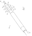
- the electrode assembly 140 is an elongate structure that includes two or more electrodes, for example, at least a first electrode 150 and a second electrode 152 , where the first electrode 150 and the second electrode 152 are defined in part by an outer surface, such as a diameter 154 .
- the elongate structure extends from a first end 142 to a second end 144 , where the elongate structure is defined in part by a longitudinal axis 146 , and optionally a lumen 148 is disposed along the longitudinal axis 146 .
- the first electrode 150 is disposed at the first end 142
- the second electrode 152 is disposed at the second end 144 .
- At least one electrode interconnect 160 Disposed between the first electrode 150 and the second electrode 152 along an intermediate portion is at least one electrode interconnect 160 , examples illustrated in FIGS. 3 and 4 , where the at least one electrode interconnect 160 electrically and/or mechanically interconnects the first and second electrodes 150 , 152 . It should be noted that one or more interconnects can be disposed between the two or more electrodes. Furthermore, the interconnects can have various cross-sectional shapes, as further described below.
- the at least one electrode interconnect 160 is connected the first and second electrodes 150 , 152 at a coupling 153 , which optionally has a necked portion where the connection at the electrode is wider than the interconnect width.
- the intermediate portion includes a void and is recessed away from the outer diameter 154 , for example as illustrated in FIG. 3 .
- the recessed portion 161 has a variety of shapes.
- the recessed portion 161 can be in the form of a void, an annular recess, or a cut out.
- the recessed portion 161 allows for the interconnect 160 that is between the electrodes to be hidden or disguised from view, for example, by placing material over the interconnect ( FIG. 2 ).
- the at least one electrode interconnect 160 substantially fixates the first electrode 150 and the second electrode 152 longitudinally and/or radially to one another.
- the at least one electrode interconnect 160 prevents longitudinal and/or radial movement of the first electrode 150 relative to the second electrode 152 .
- the at least one electrode interconnect 160 is formed of a substantially rigid material, assisting in maintaining the longitudinal and/or radial spacing of the first and second electrodes 150 , 152 .
- the at least one electrode interconnect 160 is made of substantially the same material as the first and/or second electrodes 150 , 152 .
- the at least one electrode interconnect 160 is made of a material that is more rigid than the first and/or second electrodes 150 , 152 .
- the elongate structure forming the first and second electrodes 150 , 152 and the at least one electrode interconnect 160 are formed from a unitary piece of material, for example, but not limited to, molding or casting a single piece component, or removing material from a stock piece of material to form an interconnect between two or more electrodes, or forming a void along an elongate piece of material.
- the at least one electrode interconnect 160 is defined in part by an interconnect diameter 162 .
- the interconnect outer surface or diameter 162 is less than the electrode diameter 154 . This can allow for insulative material to be disposed thereover providing a visually discrete unit, and also can allow for providing an isodiametric component.
- the interconnect diameter 162 is substantially the same as the electrode diameter 154 .
- the electrode interconnect 160 is disposed along an intermediate portion of the elongate structure, and has a variety of cross-sectional shapes.
- FIGS. 3 , 4 , 6 , and 11 illustrate example interconnects having an arcuate shape, for example similar in shape to the electrode.
- the interconnect has a circular cross-section, as shown in FIG. 11 .
- Other options for interconnects include, but are not limited to, those illustrated in FIGS. 5 , and 7 - 10 , where the interconnect includes one or more planar sides. Further options include having multiple interconnects disposed between the electrodes, for example as illustrated in FIGS. 5 , 7 - 10 .
- a method for forming one or more of the electrode assemblies discussed above includes providing an elongate structure of electrically conductive material, where the elongate structure extends from a first end to a second end and defined in part by an outer perimeter, and removing a portion of material from the elongate structure, for example to form a void between two or more electrodes.
- elongate structure include stock material, for example, that is extruded with a preformed lumen therein, or electrically conductive material.
- the material is removed from the elongate structure, for example, by EDM, machining, broaching, grinding, or other material removal processes to form a void such as a cut out, a slot, a slotted portion, or a recessed portion, as discussed above and below.
- material is removed from more than one location along the outer perimeter of the intermediate portion to form, for example, multiple interconnects between the first and second electrodes.
- multiple locations can have material removed to form two, three, or more interconnects between the electrodes.
- additional material can be removed from an outer diameter surrounding the interconnect such that the interconnect has an outer diameter that is smaller than the outer diameter of the electrodes.
- the interconnect can be formed in a variety of different manners, resulting in a variety of structures and shapes for the interconnect.
- the interconnect 160 is formed by the removal of material from the outer perimeter of the elongate structure, and in one example forms a void such as a cut out 168 ( FIG. 3 ).
- the cut out 168 in one option, can be in the form of a slot or a slotted portion 169 ( FIG. 6 ) between the first and second electrodes 150 , 152 , and/or allowing for a substantially constant outer diameter for the interconnect and the first and second electrodes 150 , 152 .
- two or more interconnects are formed by milling a slot 169 within the elongate structure, where the slot 169 extends substantially traverse, in one option, relative to axis 146 .
- the slot 169 can extend entirely through the elongate structure, or can extend only partially through the elongate structure.
- the at least two interconnects 170 , 172 are connected with the first and second electrodes in the same way, for example by forming a unitary device or of a unitary piece of material, as illustrated in FIG. 7 .
- the at least two interconnects 170 , 172 have a different cross-section from one another, and/or are connected with the first and second electrodes 150 , 152 in different manners, as illustrated in FIG. 7 .
- a first interconnect 170 is formed by removing material from an elongate piece of material
- a second interconnect 172 is formed by coupling a separate non-integral component between the first and second electrodes 150 , 152 .
- interconnects can be used to create interconnected electrodes, such as rings, where the interconnects are separate components such as a rigid rod, a rigid tube, a wire, such as a somewhat flexible or rigid wire, or a flexible cable. These interconnects can have different material than the electrodes. These separate interconnect components can be joined with the electrodes through a material joining process including welding, staking, crimping, brazing, soldering, etc.
- FIGS. 8-10 illustrate additional examples of electrode assemblies formed using various methods including material removal processes. Although it should be noted that the electrode assemblies of FIGS. 8-10 can be formed using other processes, including, but not limited to, molding or casting.
- One example for forming the at least three interconnects 160 includes removing a plane of material within the elongate structure at three different locations, resulting in angled planes 173 on a side of the interconnects 160 .
- FIG. 11 illustrates yet another option for the interconnect 160 .
- Another example for forming the interconnect includes turning down an outer surface along an intermediate portion of an elongate structure to form the interconnect 160 as shown in FIG. 11 .
- the electrode assemblies can be formed in other manners, for example using molding or casting techniques, with or without secondary material removal processes such as machining. These techniques will allow for interconnected electrodes, such as electrode rings, to be formed into a component of one, unitary piece of material, having any of the structure as described above, and as illustrated in FIGS. 3-11 .
- the elongate structure of the electrode assembly can be molded or cast with a void to form a cut out or recess or recessed portion therein.
- Other options include forming at least one lumen substantially parallel with a longitudinal axis of the electrode assembly. These forming techniques would further allow for an electrode assembly that can maintain its longitudinal and/or radial spacing of electrodes.
- the lead having the lead connector and electrode assembly is introduced within the vasculature of a patient.
- the energy source such as the pulse generator and sensor, is implanted subcutaneously within the patient.
- the lead connector and electrode assembly are electrically coupled with the energy source.
- the lead connector is inserted into a socket of the energy source, and the electrode assembly, including the electrodes 150 , 152 form an electrical connection within the energy source.
- the lead connector including the various electrode assemblies discussed above, can improve reliability in electrode performance, for example, of in-line multipolar lead connectors.
- the electrode assembly of the lead connector can be made faster, more cost-effectively, and using less complex processes.
- the manufacturability and dimensional control for example longitudinal and radial dimensions, are improved with the above-discussed examples.
- the interconnect is visually discrete or substantially invisible to the user.
Abstract
An electrode assembly includes an interconnect for at least a first connector electrode and a second connector electrode, where the interconnect provides the mechanical and/or electrical connection between the electrodes. In one example, the assembly is an elongate member having material removed therefrom along an intermediate portion.
Description
“This application is a continuation of U.S. application Ser. No. 11/128,123, filed May 12, 2005 (now U.S. Pat. No. 7,962,213), which is incorporated herein by reference in its entirety for all purposes.”
Electrode assemblies for leads which conduct electrical signals to and from the heart, and more particularly, an interconnected electrode assembly for an in-line multipolar lead connector.
Pacemaker leads represent the electrical link between the pulse generator and the heart tissue, which is to be excited and/or sensed. These pacemaker leads include single or multiconductors that are connected to an electrode in an electrode assembly at an intermediate portion or distal end of a pacing lead. A connector is included at the proximal end to form the electrical connection with the pacemaker.
When leads with multiple conductors are involved, the conductors are individually, mechanically and electrically coupled with the pulse generator at a proximal end of the multiple conductors. The multiple conductors at the proximal end are electrically insulated from each other to prevent shorts and limit electrical leakage between conductors. Some therapies require electrical connection between two or more conductors somewhere along the lead. In creating these connections, some conventional assemblies can have manufacturing drawbacks, for example, the assembly process is complex and time consuming, for example in the joining processes.
Accordingly, what is needed is an improved electrode assembly that overcomes these drawbacks.
A connector apparatus includes a lead connector having a electrode assembly with at least a first electrode and a second electrode, and at least one electrode interconnect mechanically and electrically interconnected between the first electrode and the second electrode. The one, two, three or more electrode interconnects substantially fixate the first electrode and the second electrode longitudinally to one another, or prevent longitudinal and/or rotational movement of the first electrode relative to the second electrode. In an example, the electrode assembly is a unitary piece of material.
A method for forming the electrode assembly is further provided herein. The method includes providing an elongate structure of electrically conductive material, where the elongate structure extends from a first end to a second end and defined in part by an outer perimeter. The method further includes removing a first portion of the outer perimeter of the elongate structure and forming an interconnect between the first end and the second end.
These and other embodiments, aspects, advantages, and features will be set forth in part in the description which follows, and in part will become apparent to those skilled in the art by reference to the following description and referenced drawings or by practice thereof. The aspects, advantages, and features are realized and attained by means of the instrumentalities, procedures, and combinations particularly pointed out in the appended claims and their equivalents.
In the following detailed description, reference is made to the accompanying drawings, which form a part hereof, and in which is shown by way of illustration specific embodiments in which the invention may be practiced. These embodiments are described in sufficient detail to enable those skilled in the art to practice the invention, and it is to be understood that other embodiments may be utilized and that structural changes may be made without departing from the spirit and scope of the present invention. Therefore, the following detailed description is not to be taken in a limiting sense, and the scope is defined by the appended claims.
An implantable device 100, such as a lead 102 for use with an electrical stimulator 105, is illustrated in FIG. 1 . The lead 102 includes a lead body 110, and at least one conductor 120 contained within the lead body 110. In one example, the at least one conductor 120 is an elongate conductor. The lead body 110 extends from a proximal end 112 to a distal end 114. The proximal end 112 of the lead is electrically coupled with the electrical stimulator 105, for example, with a lead connector 130 (FIG. 2 ).
In one option, the electrical stimulator 105 is a pulse sensor and generator that contains electronics to sense various electrical signals of the heart and also produce current pulses for delivery to the heart. The pulse sensor and generator may also contain electronics and software necessary to detect certain types of arrhythmias and to correct for them.
The lead 102 further includes, in one option, one or more electrodes 115. The one or more electrodes 115 are each electrically coupled with the at least one conductor 120. The electrode 115 allows for electrical signals to be delivered to the tissue from the electrical stimulator 105, or sensed from the tissue to the electrical stimulator 105. The lead 102 further includes, in one option, features to allow the lead body 110 to be fixated within a patient, for example, but not limited to, passive or active fixation features.
Referring to FIG. 2 , a lead connector 130 is illustrated in greater detail, where one example of an in-line multipolar connector is illustrated. The lead connector 130 is configured to physically mate with a pulse sensor and generator (FIG. 1 ), and to electrically couple with the pulse sensor and generator. In one example, the lead connector 130 includes an electrode assembly 140 having one or more electrodes 132, such as, for example, three connector rings 134. The lead connector 130 further includes a connector pin 136. One or more of the electrodes 132 are interconnected with one another, in one example.
The lead connector 130 includes insulative material 131, and can have various visual properties. For example, the insulative material can be opaque, or substantially opaque, substantially clear, or clear. In one example, the lead connector 130 and the insulative material 131 allows for two or more electrodes 132 to be interconnected without being visible to the user, or at least visually discrete. For example electrodes 133 and 135 can be interconnected by an interconnect that is hidden by material such as the insulative material 131, as further discussed below. In another example, if the insulative material is clear, the interconnects may be geometrically small relative to the electrodes assisting in creating visual discreteness, where an interconnect may only be slightly visible upon close inspection of the lead connector 130.
Disposed between the first electrode 150 and the second electrode 152 along an intermediate portion is at least one electrode interconnect 160, examples illustrated in FIGS. 3 and 4 , where the at least one electrode interconnect 160 electrically and/or mechanically interconnects the first and second electrodes 150, 152. It should be noted that one or more interconnects can be disposed between the two or more electrodes. Furthermore, the interconnects can have various cross-sectional shapes, as further described below.
Referring to FIG. 3 , in one option, the at least one electrode interconnect 160 is connected the first and second electrodes 150, 152 at a coupling 153, which optionally has a necked portion where the connection at the electrode is wider than the interconnect width. In another example embodiment, the intermediate portion includes a void and is recessed away from the outer diameter 154, for example as illustrated in FIG. 3 . The recessed portion 161 has a variety of shapes. For example, the recessed portion 161 can be in the form of a void, an annular recess, or a cut out. The recessed portion 161 allows for the interconnect 160 that is between the electrodes to be hidden or disguised from view, for example, by placing material over the interconnect (FIG. 2 ).
In one example, the at least one electrode interconnect 160 substantially fixates the first electrode 150 and the second electrode 152 longitudinally and/or radially to one another. For example, the at least one electrode interconnect 160 prevents longitudinal and/or radial movement of the first electrode 150 relative to the second electrode 152. In one example, the at least one electrode interconnect 160 is formed of a substantially rigid material, assisting in maintaining the longitudinal and/or radial spacing of the first and second electrodes 150, 152. In another example, the at least one electrode interconnect 160 is made of substantially the same material as the first and/or second electrodes 150, 152. In yet another option, the at least one electrode interconnect 160 is made of a material that is more rigid than the first and/or second electrodes 150, 152. In yet another example, the elongate structure forming the first and second electrodes 150, 152 and the at least one electrode interconnect 160 are formed from a unitary piece of material, for example, but not limited to, molding or casting a single piece component, or removing material from a stock piece of material to form an interconnect between two or more electrodes, or forming a void along an elongate piece of material.
The at least one electrode interconnect 160 is defined in part by an interconnect diameter 162. In one or more options, for example as shown in FIGS. 3 , 7, 8, 9, 10, and 11, the interconnect outer surface or diameter 162 is less than the electrode diameter 154. This can allow for insulative material to be disposed thereover providing a visually discrete unit, and also can allow for providing an isodiametric component. In other options, as shown for example in FIGS. 4-6 , the interconnect diameter 162 is substantially the same as the electrode diameter 154.
The electrode interconnect 160 is disposed along an intermediate portion of the elongate structure, and has a variety of cross-sectional shapes. For example, FIGS. 3 , 4, 6, and 11 illustrate example interconnects having an arcuate shape, for example similar in shape to the electrode. In a further option, the interconnect has a circular cross-section, as shown in FIG. 11 . Other options for interconnects include, but are not limited to, those illustrated in FIGS. 5 , and 7-10, where the interconnect includes one or more planar sides. Further options include having multiple interconnects disposed between the electrodes, for example as illustrated in FIGS. 5 , 7-10.
Various methods can be used to form the electrode assembly 160. For example, a method for forming one or more of the electrode assemblies discussed above, includes providing an elongate structure of electrically conductive material, where the elongate structure extends from a first end to a second end and defined in part by an outer perimeter, and removing a portion of material from the elongate structure, for example to form a void between two or more electrodes. Examples of such elongate structure include stock material, for example, that is extruded with a preformed lumen therein, or electrically conductive material. The material is removed from the elongate structure, for example, by EDM, machining, broaching, grinding, or other material removal processes to form a void such as a cut out, a slot, a slotted portion, or a recessed portion, as discussed above and below. In one option, material is removed from more than one location along the outer perimeter of the intermediate portion to form, for example, multiple interconnects between the first and second electrodes. For example, multiple locations can have material removed to form two, three, or more interconnects between the electrodes. In removing the material, additional material can be removed from an outer diameter surrounding the interconnect such that the interconnect has an outer diameter that is smaller than the outer diameter of the electrodes.
The interconnect can be formed in a variety of different manners, resulting in a variety of structures and shapes for the interconnect. In one option, the interconnect 160 is formed by the removal of material from the outer perimeter of the elongate structure, and in one example forms a void such as a cut out 168 (FIG. 3 ). The cut out 168, in one option, can be in the form of a slot or a slotted portion 169 (FIG. 6 ) between the first and second electrodes 150, 152, and/or allowing for a substantially constant outer diameter for the interconnect and the first and second electrodes 150, 152. In another example, two or more interconnects are formed by milling a slot 169 within the elongate structure, where the slot 169 extends substantially traverse, in one option, relative to axis 146. The slot 169 can extend entirely through the elongate structure, or can extend only partially through the elongate structure.
In one option, the at least two interconnects 170, 172 are connected with the first and second electrodes in the same way, for example by forming a unitary device or of a unitary piece of material, as illustrated in FIG. 7 . In another option, the at least two interconnects 170, 172 have a different cross-section from one another, and/or are connected with the first and second electrodes 150, 152 in different manners, as illustrated in FIG. 7 . For example, a first interconnect 170 is formed by removing material from an elongate piece of material, and a second interconnect 172 is formed by coupling a separate non-integral component between the first and second electrodes 150, 152.
Other interconnects can be used to create interconnected electrodes, such as rings, where the interconnects are separate components such as a rigid rod, a rigid tube, a wire, such as a somewhat flexible or rigid wire, or a flexible cable. These interconnects can have different material than the electrodes. These separate interconnect components can be joined with the electrodes through a material joining process including welding, staking, crimping, brazing, soldering, etc.
The electrode assemblies can be formed in other manners, for example using molding or casting techniques, with or without secondary material removal processes such as machining. These techniques will allow for interconnected electrodes, such as electrode rings, to be formed into a component of one, unitary piece of material, having any of the structure as described above, and as illustrated in FIGS. 3-11 . For example, the elongate structure of the electrode assembly can be molded or cast with a void to form a cut out or recess or recessed portion therein. Other options include forming at least one lumen substantially parallel with a longitudinal axis of the electrode assembly. These forming techniques would further allow for an electrode assembly that can maintain its longitudinal and/or radial spacing of electrodes.
During use of the device, the lead having the lead connector and electrode assembly, including the various options discussed above, is introduced within the vasculature of a patient. The energy source, such as the pulse generator and sensor, is implanted subcutaneously within the patient. The lead connector and electrode assembly are electrically coupled with the energy source. For example, the lead connector is inserted into a socket of the energy source, and the electrode assembly, including the electrodes 150, 152 form an electrical connection within the energy source.
Advantageously, the lead connector including the various electrode assemblies discussed above, can improve reliability in electrode performance, for example, of in-line multipolar lead connectors. The electrode assembly of the lead connector can be made faster, more cost-effectively, and using less complex processes. Furthermore, the manufacturability and dimensional control, for example longitudinal and radial dimensions, are improved with the above-discussed examples. Additionally, the interconnect is visually discrete or substantially invisible to the user.
It is to be understood that the above description is intended to be illustrative, and not restrictive. Although the use of the implantable device has been described for use with a lead in, for example, a cardiac stimulation system, the implantable device could as well be applied to other types of body stimulating systems. It should be noted that the above discusses electrode assemblies having two or more electrodes, and one or more interconnects, and is not limited to a particular number of electrodes and/or interconnects. Many other embodiments will be apparent to those of skill in the art upon reviewing the above description. The scope should, therefore, be determined with reference to the appended claims, along with the full scope of equivalents to which such claims are entitled.
Claims (20)
1. An apparatus for coupling an implantable lead to an implantable stimulator, the apparatus comprising:
a lead connector located at a proximal end of the implantable lead, the lead connector having an electrode assembly including an elongate unitary member extending from a first end to a second end, and an intermediate portion located between the first and second ends;
the first end forming a first electrode and the second end forming a second electrode; and
the intermediate portion including a plurality of elongate electrode interconnects extending between the first and second electrodes, and at least one void disposed between the first and second electrodes.
2. The apparatus of claim 1 , wherein an outer perimeter of at least one electrode interconnect is substantially flush with an outer circumference of the first and second electrodes.
3. The apparatus of claim 1 , wherein an outer perimeter of at least one electrode interconnect is recessed away from an outer circumference of the first and second electrodes.
4. The apparatus of claim 1 , wherein at least one of the electrode interconnects electrically connects the first electrode to the second electrode.
5. The apparatus of claim 1 , wherein the electrode interconnects extend lengthwise along a longitudinal axis of the elongate unitary member.
6. The apparatus of claim 1 , wherein the electrode interconnects are configured to prevent longitudinal and radial movement of the first electrode relative to the second electrode.
7. The apparatus of claim 1 , wherein the electrode interconnects, the first electrode, and the second electrode are formed of a single, unitary member.
8. The apparatus of claim 1 , wherein each electrode interconnect includes one or more planar sides.
9. The apparatus of claim 1 , wherein the first and second electrodes each comprise a first material, and wherein the electrode interconnects each comprise a second material having a rigidity greater than the first material.
10. The apparatus of claim 1 , wherein the void includes a recessed portion disposed along an outer perimeter of the intermediate portion.
11. The apparatus of claim 1 , wherein the first and second electrodes are annular-shaped electrodes.
12. An apparatus for coupling an implantable lead to an implantable stimulator, the apparatus comprising:
a lead connector located at a proximal end of the implantable lead, the lead connector having an electrode assembly including an elongate unitary member extending from a first end to a second end, and an intermediate portion located between the first and second ends;
the first end forming a first electrode and the second end forming a second electrode; and
the intermediate portion including a first elongate electrode interconnect extending lengthwise along a longitudinal axis of the elongate unitary member between the first and second electrodes, and a second elongate electrode interconnect extending lengthwise along the longitudinal axis between the first and second electrodes, and at least one void disposed between the first and second electrodes;
wherein the first and second elongate electrode interconnects are configured to prevent longitudinal and radial movement of the first electrode relative to the second electrode.
13. An electrode assembly for an implantable lead, the electrode assembly comprising:
an elongate unitary member extending from a first end to a second end, and including an intermediate portion located between the first and second ends;
the first end forming a first electrode and the second end forming a second electrode; and
the intermediate portion including a plurality of elongate electrode interconnects extending lengthwise along a longitudinal axis of the elongate unitary member between the first and second electrodes, and at least one void disposed between the first and second electrodes.
14. The assembly of claim 13 , wherein an outer perimeter of at least one electrode interconnect is substantially flush with an outer circumference of the first and second electrodes.
15. The assembly of claim 13 , wherein an outer perimeter of at least one electrode interconnect is recessed away from an outer circumference of the first and second electrodes.
16. The assembly of claim 13 , wherein at least one of the electrode interconnects electrically connects the first electrode to the second electrode.
17. The assembly of claim 13 , wherein the electrode interconnects are configured to prevent longitudinal and radial movement of the first electrode relative to the second electrode.
18. The assembly of claim 13 , wherein each electrode interconnect includes one or more planar sides.
19. The assembly of claim 13 , wherein the first and second electrodes each comprise a first material, and wherein the electrode interconnects each comprise a second material having a rigidity greater than the first material.
20. The assembly of claim 13 , wherein the first and second electrodes are annular-shaped electrodes.
Priority Applications (1)
| Application Number | Priority Date | Filing Date | Title |
|---|---|---|---|
| US13/100,558 US8577463B2 (en) | 2005-05-12 | 2011-05-04 | Interconnected electrode assembly for a lead connector and method therefor |
Applications Claiming Priority (2)
| Application Number | Priority Date | Filing Date | Title |
|---|---|---|---|
| US11/128,123 US7962213B2 (en) | 2005-05-12 | 2005-05-12 | Interconnected electrode assembly for a lead connector and method therefor |
| US13/100,558 US8577463B2 (en) | 2005-05-12 | 2011-05-04 | Interconnected electrode assembly for a lead connector and method therefor |
Related Parent Applications (1)
| Application Number | Title | Priority Date | Filing Date |
|---|---|---|---|
| US11/128,123 Continuation US7962213B2 (en) | 2005-05-12 | 2005-05-12 | Interconnected electrode assembly for a lead connector and method therefor |
Publications (2)
| Publication Number | Publication Date |
|---|---|
| US20110208282A1 US20110208282A1 (en) | 2011-08-25 |
| US8577463B2 true US8577463B2 (en) | 2013-11-05 |
Family
ID=37420166
Family Applications (2)
| Application Number | Title | Priority Date | Filing Date |
|---|---|---|---|
| US11/128,123 Expired - Fee Related US7962213B2 (en) | 2005-05-12 | 2005-05-12 | Interconnected electrode assembly for a lead connector and method therefor |
| US13/100,558 Active 2025-10-30 US8577463B2 (en) | 2005-05-12 | 2011-05-04 | Interconnected electrode assembly for a lead connector and method therefor |
Family Applications Before (1)
| Application Number | Title | Priority Date | Filing Date |
|---|---|---|---|
| US11/128,123 Expired - Fee Related US7962213B2 (en) | 2005-05-12 | 2005-05-12 | Interconnected electrode assembly for a lead connector and method therefor |
Country Status (1)
| Country | Link |
|---|---|
| US (2) | US7962213B2 (en) |
Cited By (2)
| Publication number | Priority date | Publication date | Assignee | Title |
|---|---|---|---|---|
| US20130267127A1 (en) * | 2012-04-04 | 2013-10-10 | Luciano Di Maio | Electrical connection plug for multipolar lead of active implantable medical device |
| US9368925B2 (en) | 2009-12-30 | 2016-06-14 | Cardiac Pacemakers, Inc. | Terminal connector assembly for a medical electrical lead |
Families Citing this family (31)
| Publication number | Priority date | Publication date | Assignee | Title |
|---|---|---|---|---|
| US8000802B2 (en) | 2002-04-22 | 2011-08-16 | Medtronic, Inc. | Implantable lead with coplanar contact coupling |
| US7184840B2 (en) * | 2002-04-22 | 2007-02-27 | Medtronic, Inc. | Implantable lead with isolated contact coupling |
| US20030199952A1 (en) * | 2002-04-22 | 2003-10-23 | Stolz Brian T. | Implantable lead with improved distal tip |
| US7962213B2 (en) * | 2005-05-12 | 2011-06-14 | Cardiac Pacemakers, Inc. | Interconnected electrode assembly for a lead connector and method therefor |
| US8437866B2 (en) * | 2005-05-12 | 2013-05-07 | Cardiac Pacemakers, Inc. | Internally interconnected electrode assembly for a lead and method therefor |
| US7583999B2 (en) | 2006-07-31 | 2009-09-01 | Cranial Medical Systems, Inc. | Multi-channel connector for brain stimulation system |
| US7917229B2 (en) | 2006-08-31 | 2011-03-29 | Cardiac Pacemakers, Inc. | Lead assembly including a polymer interconnect and methods related thereto |
| DE102008008927A1 (en) * | 2008-02-13 | 2009-08-20 | Biotronik Crm Patent Ag | Electrode lead and fitting for electromedical implants |
| US8219209B2 (en) | 2008-08-15 | 2012-07-10 | Cardiac Pacemakers, Inc. | Implantable medical lead having reduced dimension tubing transition |
| US8548601B2 (en) | 2008-09-15 | 2013-10-01 | Boston Scientific Neuromodulation Corporation | Lead connection system for an implantable electrical stimulation system and methods for making and using the systems |
| US8910376B2 (en) * | 2009-05-27 | 2014-12-16 | Boston Scientific Neuromodulation Corporation | Systems and methods for forming an end of an elongated member of an electrical stimulation system |
| US8600507B2 (en) * | 2009-07-21 | 2013-12-03 | Boston Scientific Neuromodulation Corporation | Multi-port modular connector for implantable electrical stimulation systems and methods of making and using |
| AU2011235161B2 (en) * | 2010-04-02 | 2016-05-26 | Boston Scientific Neuromodulation Corporation | Directional lead assembly |
| US20120151765A1 (en) * | 2010-12-21 | 2012-06-21 | Pacesetter, Inc. | Lead connector end with integrated shunt |
| US9079020B2 (en) * | 2012-10-17 | 2015-07-14 | Cardiac Pacemakers, Inc. | Terminal ring configuration to prevent improper IS4 lead connector electrical contact with DF4 connector port |
| US9106004B2 (en) * | 2013-12-19 | 2015-08-11 | Medtronic, Inc. | Implantable medical electrical leads and connector assemblies thereof |
| US9956394B2 (en) | 2015-09-10 | 2018-05-01 | Boston Scientific Neuromodulation Corporation | Connectors for electrical stimulation systems and methods of making and using |
| US10342983B2 (en) | 2016-01-14 | 2019-07-09 | Boston Scientific Neuromodulation Corporation | Systems and methods for making and using connector contact arrays for electrical stimulation systems |
| US10201713B2 (en) | 2016-06-20 | 2019-02-12 | Boston Scientific Neuromodulation Corporation | Threaded connector assembly and methods of making and using the same |
| US10307602B2 (en) | 2016-07-08 | 2019-06-04 | Boston Scientific Neuromodulation Corporation | Threaded connector assembly and methods of making and using the same |
| US10543374B2 (en) | 2016-09-30 | 2020-01-28 | Boston Scientific Neuromodulation Corporation | Connector assemblies with bending limiters for electrical stimulation systems and methods of making and using same |
| US10905871B2 (en) | 2017-01-27 | 2021-02-02 | Boston Scientific Neuromodulation Corporation | Lead assemblies with arrangements to confirm alignment between terminals and contacts |
| WO2018160495A1 (en) | 2017-02-28 | 2018-09-07 | Boston Scientific Neuromodulation Corporation | Toolless connector for latching stimulation leads and methods of making and using |
| US10603499B2 (en) | 2017-04-07 | 2020-03-31 | Boston Scientific Neuromodulation Corporation | Tapered implantable lead and connector interface and methods of making and using |
| EP3658228A1 (en) | 2017-07-25 | 2020-06-03 | Boston Scientific Neuromodulation Corporation | Systems and methods for making and using an enhanced connector of an electrical stimulation system |
| US10639485B2 (en) | 2017-09-15 | 2020-05-05 | Boston Scientific Neuromodulation Corporation | Actuatable lead connector for an operating room cable assembly and methods of making and using |
| US11045656B2 (en) | 2017-09-15 | 2021-06-29 | Boston Scientific Neuromodulation Corporation | Biased lead connector for operating room cable assembly and methods of making and using |
| US11139603B2 (en) | 2017-10-03 | 2021-10-05 | Boston Scientific Neuromodulation Corporation | Connectors with spring contacts for electrical stimulation systems and methods of making and using same |
| US11103712B2 (en) | 2018-01-16 | 2021-08-31 | Boston Scientific Neuromodulation Corporation | Connector assemblies with novel spacers for electrical stimulation systems and methods of making and using same |
| US11052259B2 (en) | 2018-05-11 | 2021-07-06 | Boston Scientific Neuromodulation Corporation | Connector assembly for an electrical stimulation system and methods of making and using |
| US11357992B2 (en) | 2019-05-03 | 2022-06-14 | Boston Scientific Neuromodulation Corporation | Connector assembly for an electrical stimulation system and methods of making and using |
Citations (39)
| Publication number | Priority date | Publication date | Assignee | Title |
|---|---|---|---|---|
| US3657744A (en) | 1970-05-08 | 1972-04-25 | Univ Minnesota | Method for fixing prosthetic implants in a living body |
| US5056517A (en) | 1989-07-24 | 1991-10-15 | Consiglio Nazionale Delle Ricerche | Biomagnetically localizable multipurpose catheter and method for magnetocardiographic guided intracardiac mapping, biopsy and ablation of cardiac arrhythmias |
| US5304219A (en) | 1991-06-14 | 1994-04-19 | Siemens Pacesetter, Inc. | Multipolar in-line proximal connector assembly for an implantable stimulation device |
| US5385409A (en) | 1991-10-30 | 1995-01-31 | Ide; Russell D. | Non-contacting mechanical face seal of the gap-type |
| US5487757A (en) | 1993-07-20 | 1996-01-30 | Medtronic Cardiorhythm | Multicurve deflectable catheter |
| US5669790A (en) | 1995-12-07 | 1997-09-23 | Ventritex, Inc. | Lead lumen sealing device |
| US6026567A (en) | 1995-05-11 | 2000-02-22 | Medtronic, Inc. | Medical lead with stranded conductors |
| US20010037135A1 (en) | 2000-05-15 | 2001-11-01 | Pianca Anne M. | Lead with polymeric tubular liner for guidewire and stylet insertion |
| US20020029074A1 (en) | 1999-05-21 | 2002-03-07 | Claudiu-Gheorghe Treaba | Cochlear implant electrode array |
| US20020077685A1 (en) | 2000-12-20 | 2002-06-20 | Medtronic, Inc. | Medical electrical lead and method of use |
| US6434430B2 (en) | 1999-03-18 | 2002-08-13 | Medtronic, Inc. | Co-extruded, multi-lumen medical lead |
| US20030023294A1 (en) | 2001-05-02 | 2003-01-30 | Krall Robert C. | Defibrillation electrode cover |
| US20030036779A1 (en) | 2000-12-15 | 2003-02-20 | Randy Westlund | Multi-polar connector |
| US20030074031A1 (en) | 2000-12-15 | 2003-04-17 | Ley Gregory R. | Micro terminal connector |
| US6623480B1 (en) | 1998-07-24 | 2003-09-23 | University Of Kentucky Research Foundation | Flexible recording/high energy electrode catheter with anchor for ablation of atrial flutter by radio frequency energy |
| US6650921B2 (en) | 1997-07-30 | 2003-11-18 | Intermedics Inc. | Cardiac lead with minimized inside diameter of sleeve |
| US20040054390A1 (en) | 2002-09-13 | 2004-03-18 | Zarembo Paul E. | Method and device for supporting or strengthening a portion of a lead |
| US20040064174A1 (en) | 2002-09-27 | 2004-04-01 | Belden Elisabeth L. | Methods and apparatus for joining small diameter conductors within medical electrical leads |
| US20040068313A1 (en) | 2002-10-04 | 2004-04-08 | Jenney Christopher R. | Body implantable lead comprising electrically conductive polymer conductors |
| US6725096B2 (en) | 2000-05-05 | 2004-04-20 | Advanced Bionics Corporation | Multiple in-line contact connector |
| US6785576B2 (en) | 1997-04-21 | 2004-08-31 | Medtronic, Inc. | Medical electrical lead |
| US6792317B1 (en) | 2001-05-24 | 2004-09-14 | Pacesetter, Inc. | Implantable electric lead and electrical coupling |
| US20040215303A1 (en) | 2003-04-25 | 2004-10-28 | Sage Shahn S. | Implantable biomedical electrical connectors having integral side and inner walls |
| US20040215282A1 (en) | 2003-04-23 | 2004-10-28 | Hans Van Der Weijden | Connector module designs for implantable medical devices |
| US20040230268A1 (en) | 2003-05-13 | 2004-11-18 | Medtronic, Inc. | Medical lead adaptor assembly |
| US20050027325A1 (en) | 2003-07-31 | 2005-02-03 | Jay Lahti | Connector assembly for connecting a lead and an implantable medical device |
| US20060041299A1 (en) | 2004-08-23 | 2006-02-23 | Medtronic, Inc. | Novel distal portions for medical electrical leads |
| US20060259105A1 (en) | 2005-05-12 | 2006-11-16 | Cardiac Pacemakers, Inc. | Internally interconnected electrode assembly for a lead and method therefor |
| US7160311B2 (en) | 1999-04-16 | 2007-01-09 | Integrated Vascular Interventional Technologies, L.C. (Ivit Lc) | Locking compression plate anastomosis apparatus |
| US20070027517A1 (en) | 2005-07-29 | 2007-02-01 | Bischoff Thomas C | Medical electrical lead connector ring |
| US7175478B2 (en) | 2004-09-20 | 2007-02-13 | Ela Medical S.A.S. | Modular electric terminal connector, in particular for a mono-body probe of defibrillation |
| US20080027504A1 (en) | 2006-07-31 | 2008-01-31 | Cranial Medical Systems, Inc. | Lead and methods for brain monitoring and modulation |
| US20080046059A1 (en) | 2006-08-04 | 2008-02-21 | Zarembo Paul E | Lead including a heat fused or formed lead body |
| US20080114230A1 (en) | 2006-11-14 | 2008-05-15 | Bruce Addis | Electrode support |
| US20080154328A1 (en) | 2006-12-15 | 2008-06-26 | Proteus Biomedical, Inc. | Universal connector for implantable medical device |
| US7648401B2 (en) | 2008-02-13 | 2010-01-19 | Biotronik Crm Patent Ag | Electrode line and connecting piece for electromedical implants |
| US7962213B2 (en) * | 2005-05-12 | 2011-06-14 | Cardiac Pacemakers, Inc. | Interconnected electrode assembly for a lead connector and method therefor |
| US20110159748A1 (en) | 2009-12-30 | 2011-06-30 | Lily Lim | Terminal connector assembly for a medical electrical lead |
| US8126557B2 (en) | 2009-02-13 | 2012-02-28 | Pacesetter, Inc. | Lead connector pin and body assembly and method of manufacture |
-
2005
- 2005-05-12 US US11/128,123 patent/US7962213B2/en not_active Expired - Fee Related
-
2011
- 2011-05-04 US US13/100,558 patent/US8577463B2/en active Active
Patent Citations (41)
| Publication number | Priority date | Publication date | Assignee | Title |
|---|---|---|---|---|
| US3657744A (en) | 1970-05-08 | 1972-04-25 | Univ Minnesota | Method for fixing prosthetic implants in a living body |
| US5056517A (en) | 1989-07-24 | 1991-10-15 | Consiglio Nazionale Delle Ricerche | Biomagnetically localizable multipurpose catheter and method for magnetocardiographic guided intracardiac mapping, biopsy and ablation of cardiac arrhythmias |
| US5304219A (en) | 1991-06-14 | 1994-04-19 | Siemens Pacesetter, Inc. | Multipolar in-line proximal connector assembly for an implantable stimulation device |
| US5385409A (en) | 1991-10-30 | 1995-01-31 | Ide; Russell D. | Non-contacting mechanical face seal of the gap-type |
| US5487757A (en) | 1993-07-20 | 1996-01-30 | Medtronic Cardiorhythm | Multicurve deflectable catheter |
| US6026567A (en) | 1995-05-11 | 2000-02-22 | Medtronic, Inc. | Medical lead with stranded conductors |
| US5669790A (en) | 1995-12-07 | 1997-09-23 | Ventritex, Inc. | Lead lumen sealing device |
| US6785576B2 (en) | 1997-04-21 | 2004-08-31 | Medtronic, Inc. | Medical electrical lead |
| US6650921B2 (en) | 1997-07-30 | 2003-11-18 | Intermedics Inc. | Cardiac lead with minimized inside diameter of sleeve |
| US6623480B1 (en) | 1998-07-24 | 2003-09-23 | University Of Kentucky Research Foundation | Flexible recording/high energy electrode catheter with anchor for ablation of atrial flutter by radio frequency energy |
| US6434430B2 (en) | 1999-03-18 | 2002-08-13 | Medtronic, Inc. | Co-extruded, multi-lumen medical lead |
| US7160311B2 (en) | 1999-04-16 | 2007-01-09 | Integrated Vascular Interventional Technologies, L.C. (Ivit Lc) | Locking compression plate anastomosis apparatus |
| US20020029074A1 (en) | 1999-05-21 | 2002-03-07 | Claudiu-Gheorghe Treaba | Cochlear implant electrode array |
| US6725096B2 (en) | 2000-05-05 | 2004-04-20 | Advanced Bionics Corporation | Multiple in-line contact connector |
| US20010037135A1 (en) | 2000-05-15 | 2001-11-01 | Pianca Anne M. | Lead with polymeric tubular liner for guidewire and stylet insertion |
| US20030036779A1 (en) | 2000-12-15 | 2003-02-20 | Randy Westlund | Multi-polar connector |
| US20030074031A1 (en) | 2000-12-15 | 2003-04-17 | Ley Gregory R. | Micro terminal connector |
| US6912423B2 (en) | 2000-12-15 | 2005-06-28 | Cardiac Pacemakers, Inc. | Terminal connector assembly for a medical device and method therefor |
| US7234977B2 (en) | 2000-12-15 | 2007-06-26 | Cardiac Pacemakers, Inc. | Multi-polar connector |
| US20020077685A1 (en) | 2000-12-20 | 2002-06-20 | Medtronic, Inc. | Medical electrical lead and method of use |
| US20030023294A1 (en) | 2001-05-02 | 2003-01-30 | Krall Robert C. | Defibrillation electrode cover |
| US6792317B1 (en) | 2001-05-24 | 2004-09-14 | Pacesetter, Inc. | Implantable electric lead and electrical coupling |
| US20040054390A1 (en) | 2002-09-13 | 2004-03-18 | Zarembo Paul E. | Method and device for supporting or strengthening a portion of a lead |
| US20040064174A1 (en) | 2002-09-27 | 2004-04-01 | Belden Elisabeth L. | Methods and apparatus for joining small diameter conductors within medical electrical leads |
| US20040068313A1 (en) | 2002-10-04 | 2004-04-08 | Jenney Christopher R. | Body implantable lead comprising electrically conductive polymer conductors |
| US20040215282A1 (en) | 2003-04-23 | 2004-10-28 | Hans Van Der Weijden | Connector module designs for implantable medical devices |
| US20040215303A1 (en) | 2003-04-25 | 2004-10-28 | Sage Shahn S. | Implantable biomedical electrical connectors having integral side and inner walls |
| US20040230268A1 (en) | 2003-05-13 | 2004-11-18 | Medtronic, Inc. | Medical lead adaptor assembly |
| US20050027325A1 (en) | 2003-07-31 | 2005-02-03 | Jay Lahti | Connector assembly for connecting a lead and an implantable medical device |
| US20060041299A1 (en) | 2004-08-23 | 2006-02-23 | Medtronic, Inc. | Novel distal portions for medical electrical leads |
| US7175478B2 (en) | 2004-09-20 | 2007-02-13 | Ela Medical S.A.S. | Modular electric terminal connector, in particular for a mono-body probe of defibrillation |
| US7962213B2 (en) * | 2005-05-12 | 2011-06-14 | Cardiac Pacemakers, Inc. | Interconnected electrode assembly for a lead connector and method therefor |
| US20060259105A1 (en) | 2005-05-12 | 2006-11-16 | Cardiac Pacemakers, Inc. | Internally interconnected electrode assembly for a lead and method therefor |
| US20070027517A1 (en) | 2005-07-29 | 2007-02-01 | Bischoff Thomas C | Medical electrical lead connector ring |
| US20080027504A1 (en) | 2006-07-31 | 2008-01-31 | Cranial Medical Systems, Inc. | Lead and methods for brain monitoring and modulation |
| US20080046059A1 (en) | 2006-08-04 | 2008-02-21 | Zarembo Paul E | Lead including a heat fused or formed lead body |
| US20080114230A1 (en) | 2006-11-14 | 2008-05-15 | Bruce Addis | Electrode support |
| US20080154328A1 (en) | 2006-12-15 | 2008-06-26 | Proteus Biomedical, Inc. | Universal connector for implantable medical device |
| US7648401B2 (en) | 2008-02-13 | 2010-01-19 | Biotronik Crm Patent Ag | Electrode line and connecting piece for electromedical implants |
| US8126557B2 (en) | 2009-02-13 | 2012-02-28 | Pacesetter, Inc. | Lead connector pin and body assembly and method of manufacture |
| US20110159748A1 (en) | 2009-12-30 | 2011-06-30 | Lily Lim | Terminal connector assembly for a medical electrical lead |
Non-Patent Citations (1)
| Title |
|---|
| International Search Report and Written Opinion issued in PCT/US2010/057025 dated Mar. 2, 2011. |
Cited By (3)
| Publication number | Priority date | Publication date | Assignee | Title |
|---|---|---|---|---|
| US9368925B2 (en) | 2009-12-30 | 2016-06-14 | Cardiac Pacemakers, Inc. | Terminal connector assembly for a medical electrical lead |
| US20130267127A1 (en) * | 2012-04-04 | 2013-10-10 | Luciano Di Maio | Electrical connection plug for multipolar lead of active implantable medical device |
| US8911265B2 (en) * | 2012-04-04 | 2014-12-16 | Sorin Crm Sas | Electrical connection plug for multipolar lead of active implantable medical device |
Also Published As
| Publication number | Publication date |
|---|---|
| US7962213B2 (en) | 2011-06-14 |
| US20060259106A1 (en) | 2006-11-16 |
| US20110208282A1 (en) | 2011-08-25 |
Similar Documents
| Publication | Publication Date | Title |
|---|---|---|
| US8577463B2 (en) | Interconnected electrode assembly for a lead connector and method therefor | |
| US9833611B2 (en) | Systems and methods for making and using improved contact arrays for electrical stimulation systems | |
| US8382529B2 (en) | Terminal connector assembly for a medical electrical lead | |
| US7546165B2 (en) | Interconnections of implantable lead conductors and electrodes and reinforcement therefor | |
| US7761985B2 (en) | Method of manufacturing a medical lead | |
| US6456888B1 (en) | Geometry for coupling and electrode to a conductor | |
| JP5525624B2 (en) | Medical lead wire with coil conductor having two or more areas and method for constructing the coil conductor | |
| US6671553B1 (en) | Implantable cardiac lead having terminating connector strain relief and method of manufacture | |
| US20070156216A1 (en) | Electrode and insulation assembly for a lead and method therefor | |
| US20050272280A1 (en) | Lead adaptor having low resistance conductors and/or encapsulated housing | |
| EP2424613B1 (en) | Implantable electric lead | |
| US10143837B2 (en) | Method for manufacturing an implantable cardiac electrotherapy lead | |
| US7031774B1 (en) | Switch for electrode selections in Single-pass Atrial/Ventricular leads | |
| US7921554B2 (en) | Method for manufacturing a medical electrical lead connector ring | |
| US8437866B2 (en) | Internally interconnected electrode assembly for a lead and method therefor | |
| US6463333B1 (en) | Implantable left atrial stimulation probe for the venous coronary network | |
| CN217066535U (en) | Carrier terminal and subcutaneous implantation tool |
Legal Events
| Date | Code | Title | Description |
|---|---|---|---|
| FEPP | Fee payment procedure |
Free format text: PAYOR NUMBER ASSIGNED (ORIGINAL EVENT CODE: ASPN); ENTITY STATUS OF PATENT OWNER: LARGE ENTITY |
|
| STCF | Information on status: patent grant |
Free format text: PATENTED CASE |
|
| FPAY | Fee payment |
Year of fee payment: 4 |
|
| MAFP | Maintenance fee payment |
Free format text: PAYMENT OF MAINTENANCE FEE, 8TH YEAR, LARGE ENTITY (ORIGINAL EVENT CODE: M1552); ENTITY STATUS OF PATENT OWNER: LARGE ENTITY Year of fee payment: 8 |