US8623441B2 - Method and apparatus for controlling brewed beverage quality - Google Patents

Method and apparatus for controlling brewed beverage quality Download PDF

Info

Publication number
US8623441B2
US8623441B2 US13/050,852 US201113050852A US8623441B2 US 8623441 B2 US8623441 B2 US 8623441B2 US 201113050852 A US201113050852 A US 201113050852A US 8623441 B2 US8623441 B2 US 8623441B2
Authority
US
United States
Prior art keywords
brewing
brewing chamber
controller
brewed liquid
coffee
Prior art date
Legal status (The legal status is an assumption and is not a legal conclusion. Google has not performed a legal analysis and makes no representation as to the accuracy of the status listed.)
Active, expires
Application number
US13/050,852
Other versions
US20110212229A1 (en
Inventor
James M. McLaughlin
Quan H. Nguyen
Christopher D. Collier
Eileen M. Nall
Lucas A. Marks
Carrie M. Rebhuhn
Current Assignee (The listed assignees may be inaccurate. Google has not performed a legal analysis and makes no representation or warranty as to the accuracy of the list.)
Concordia Coffee Co Inc
Original Assignee
Concordia Coffee Co Inc
Priority date (The priority date is an assumption and is not a legal conclusion. Google has not performed a legal analysis and makes no representation as to the accuracy of the date listed.)
Filing date
Publication date
Priority claimed from US13/038,195 external-priority patent/US8247010B2/en
Application filed by Concordia Coffee Co Inc filed Critical Concordia Coffee Co Inc
Priority to US13/050,852 priority Critical patent/US8623441B2/en
Priority to US13/086,257 priority patent/US8616116B2/en
Assigned to CONCORDIA COFFEE COMPANY, INC. reassignment CONCORDIA COFFEE COMPANY, INC. ASSIGNMENT OF ASSIGNORS INTEREST (SEE DOCUMENT FOR DETAILS). Assignors: REBHUHN, CARRIE M., NALL, EILEEN M., MARKS, LUCAS A., COLLIER, CHRISTOPHER D., MCLAUGHLIN, JAMES M., NGUYEN, QUAN H.
Publication of US20110212229A1 publication Critical patent/US20110212229A1/en
Assigned to COMERICA BANK reassignment COMERICA BANK SECURITY AGREEMENT Assignors: CONCORDIA COFFEE COMPANY, INC.
Application granted granted Critical
Publication of US8623441B2 publication Critical patent/US8623441B2/en
Active legal-status Critical Current
Adjusted expiration legal-status Critical

Links

Images

Classifications

    • AHUMAN NECESSITIES
    • A47FURNITURE; DOMESTIC ARTICLES OR APPLIANCES; COFFEE MILLS; SPICE MILLS; SUCTION CLEANERS IN GENERAL
    • A47JKITCHEN EQUIPMENT; COFFEE MILLS; SPICE MILLS; APPARATUS FOR MAKING BEVERAGES
    • A47J31/00Apparatus for making beverages
    • A47J31/24Coffee-making apparatus in which hot water is passed through the filter under pressure, i.e. in which the coffee grounds are extracted under pressure
    • A47J31/34Coffee-making apparatus in which hot water is passed through the filter under pressure, i.e. in which the coffee grounds are extracted under pressure with hot water under liquid pressure
    • A47J31/36Coffee-making apparatus in which hot water is passed through the filter under pressure, i.e. in which the coffee grounds are extracted under pressure with hot water under liquid pressure with mechanical pressure-producing means
    • A47J31/3604Coffee-making apparatus in which hot water is passed through the filter under pressure, i.e. in which the coffee grounds are extracted under pressure with hot water under liquid pressure with mechanical pressure-producing means with a mechanism arranged to move the brewing chamber between loading, infusing and ejecting stations
    • A47J31/3609Loose coffee being employed
    • A47J31/3614Means to perform transfer from a loading position to an infusing position

Definitions

  • Coffee preparation that is, the process of producing a beverage using the coffee bean, typically requires four basic steps be performed: (i) the raw coffee beans are roasted; (ii) the roasted coffee beans are ground; (iii) the ground coffee beans are brewed, i.e., mixed with hot water for a period of time; and (iv) the liquid coffee beverage is separated from the unwanted grounds. Additional steps may include, for example, adding milk, sweetener, flavorings, and/or other additives to the brewed liquid. Typically in much of the world, the roasted coffee beans are purchased by the user, who then performs the remaining steps.
  • Various coffee brewing systems are known in the art, ranging from personal brewers such as drip coffee makers and French presses, to large commercial systems used for producing a dizzying array of flavored espresso-based beverages.
  • Ground coffee may be brewed in a number of different ways that may be categorized into four basic methods (as discussed in http://en.wikipedia.org/wiki/Coffee_preparation).
  • the four methods are (1) boiling, for example placing ground coffee into a cup and pouring hot water over the grounds, allowing the grounds to settle; (2) steeping, for example, placing ground coffee into a French press and waiting a few minutes before depressing the filtered plunger and pouring the brewed liquid into a cup; (3) filtration, for example drip brewing wherein the ground coffee is placed in a filter holder and hot water drips onto the coffee grounds into a carafe or the like; and (4) pressure methods, for making espresso wherein hot water typically between 91° C. and 96° C. is forced under a pressure of between eight and nine atmospheres through a lightly packed matrix or “puck” of finely ground coffee.
  • brewing methods have various disadvantages. For example, boiling and steeping methods require some time, typically 4-7 minutes, to produce an optimally flavored beverage. Filtration methods may be quicker, but do not produce the full bodied coffee that many consumers prefer, and/or may require more coffee grounds to produce an acceptable flavor.
  • Coffee may be relatively quick, but requires relatively high pressures (8-9 atmospheres). Moreover, the high pressures are typically produced by steam, and the relatively high temperatures and pressures produce a very strong and distinctive flavor that some consumers may not prefer.
  • the quality of a brewed coffee depends on a number of different and often related parameters.
  • the quality of a brewed coffee will typically depend on both the amount of coffee soluble components in the brewed liquid, and which of the coffee soluble components are present. If the coffee is under-brewed, for example, certain of the desirable flavor and aroma components may not be obtained from the coffee bean, resulting in an inferior product. Conversely, if the coffee is over-brewed, certain undesirable bitter soluble components may be dissolved in the liquid, again resulting in an inferior product.
  • the quality of a brewed coffee liquid is characterized by measuring the total dissolved solids in the brewed beverage, and determining the percent of available solubles that were extracted from the coffee.
  • the rate of extraction is not constant, so prior art quality determinations are made on the final brewed product. It may be difficult or inconvenient to obtain these parameters in the final product, which is typically provided to the end user, and may include flavorings or other additives at the time of dispensing.
  • brewing apparatus with a means for regularly monitoring the quality of a brewed beverage without having to analyze the final brewed product.
  • a brewing system includes a source of brewable product, for example ground coffee or tea, a source of heated water, and a brewing chamber for brewing the product in the heated water.
  • An electronic system is provided for controlling the operation of the brewing system, preferably including a computer processor, communications facilities, and related data storage ability.
  • the system further includes an inline sensor positioned to intercept the fluid stream expelled from the brewing chamber, and to measure a one or more properties of the fluid stream, wherein the sensor generated time-dependent data corresponding to the measured property or properties. For example, the sensor may measure the total dissolved solids in the brewed liquid.
  • the data is communicated to the controller, which may use the data to continuously or periodically adjust the brewing parameters, for example, by adjusting the grinder time to adjust the amount of brewable product received into the brewing chamber.
  • the time-dependent sensor data is used to identify the brewable product, to identify the particular brand or blend of coffee used.
  • the controller uses the sensor data to monitor the operation of the brewing system, and to identify if there is a need for service or maintenance.
  • the brewing system includes a coffee grinder, and a conductivity sensor, and the controller uses the time-dependent data from the conductivity sensor to control the operation of the grinder.
  • the brewing system includes a cylindrical brewing chamber, a lower piston that is attached to a first linear actuator and sealably engages an open bottom end of the brewing chamber, an upper piston assembly that is attached to a second linear actuator and sealably and releasably engages an open upper end of the brewing chamber, and a sliding arm assembly that is attached to a third linear actuator and is operable to slide over the upper open end of the brewing chamber.
  • the brewing system includes a display for displaying the total dissolved solids or another quality of the brewed beverage based on property of the brewed liquid measured by the sensor.
  • a method for producing a brewable beverage includes providing a quantity of brewable product and heated water to a brewing chamber to produce a brewed liquid, forcing the brewed liquid from the chamber in a fluid stream, and measuring a property of the brewed liquid at a fixed location as the fluid stream flows by the fixed location to generate a time-dependent data set for the fluid stream corresponding to the measured property.
  • FIG. 1 is a front-right perspective environmental view of a beverage brewing system in accordance with the present invention
  • FIG. 2 is a plan view of the beverage brewing system shown in FIG. 1 , with some outer panels removed to expose interior components;
  • FIG. 3 is a perspective view showing the brew group for the beverage brewing system shown in FIG. 1 ;
  • FIG. 4 is a section view of the upper piston assembly shown in FIG. 3 ;
  • FIG. 5 is a section view of the lower piston assembly shown in FIG. 3 ;
  • FIGS. 6A , 6 B, 6 C, 6 D, and 6 E illustrate the brew group shown in FIG. 3 with the brewing chamber partially cut away, in various positions during the brewing cycle;
  • FIG. 7 illustrates the Coffee Brewing Control Chart
  • FIG. 8 is a simplified block diagram of the brewing system shown in FIG. 1 ;
  • FIG. 9 illustrates graphically output data from an embodiment of the sensor array for the system shown in FIG. 9 , that includes a TDS meter;
  • FIG. 10 illustrates TDS curves from the sensor array of FIG. 9 , showing curves for different coffee blends.
  • FIG. 1 shows a perspective environmental view of a brewing system 100 in accordance with the present invention, having a hopper 102 disposed at a top of the system 100 , and holding a carafe 90 in the dispensing area 104 .
  • a beverage selection and/or control panel 106 is shown generally above the dispensing area 104 .
  • the hopper 102 may define a plurality of selectable compartments containing different brewable materials, for example different types or species of coffee beans.
  • the beverage selection panel 106 may give users the option to select a beverage size (e.g., 12, 16, or 20 ounces), among beverage choices (e.g., regular coffee, decaffeinated coffee, tea), and/or among flavoring or other additive options (e.g., creamer, sweetener, syrup flavors).
  • the beverage selection panel 106 may also allow selection of a parameter of the brewed beverage (e.g., strength), and/or provide feedback regarding a quality of the brewed beverage.
  • the brewing system 100 may be suitable for brewing various brewable materials, such as ground coffee, tea, or the like. Although the following discussion may refer specifically to coffee brewing systems in places, it will be understood that the teachings of the present invention may similarly be applied to other brewing systems, including tea brewing systems.
  • FIG. 2 shows a top view of the brewing system 100 with the hopper 102 and certain other portions removed to expose internal components.
  • the brewing system 100 includes a brew group controller 110 , a power supply 112 , an optional flavoring controller 116 and a water heater/reservoir 114 .
  • a grinder assembly 120 comprising two grinders 122 , 124 is positioned to receive product, for example coffee beans, from the hopper 102 .
  • the brewable product from the grinder assembly 120 is expelled through a shared chute base 126 , and a chute assembly 160 .
  • a brew group 130 is plumbed to receive hot water from the reservoir 114 and configured to receive brewable product from the grinding assembly 120 .
  • the brew group 130 includes a cylindrical brewing chamber 132 , currently formed with a cylindrical sleeve disposed in a block assembly 131 .
  • the brewing chamber 132 is positioned to receive coffee grounds from the grinder assembly 120 .
  • the brewing chamber defines a cylindrical volume between 2 inches and 3.5 inches in diameter, and a height between 2.5 inches and 5.0 inches.
  • the brew group including brewing chamber 132 may readily be scaled to other sizes.
  • a sliding arm assembly 134 is slidably disposed over the brewing chamber 132 , and is configured to push spent grounds or other brewed material off of the block assembly 131 .
  • the sliding arm assembly 134 includes a C-shaped arm 134 A that extends across the width of the brewing chamber 132 . The lower transverse edges of the C-shaped arm 134 A are beveled.
  • the arm 134 A is drivably attached to a drive arm subassembly 134 B.
  • the drive arm subassembly 134 B is movable linearly by an actuator 134 C such that the C-shaped arm 134 A is controllably movable across the upper surface of the block assembly 131 .
  • the actuator 134 C comprises an electric motor-driven worm gear system with a toothed belt (not shown) that drivably engages the drive arm subassembly 134 B.
  • the actuator 134 C, and the piston actuators discussed below are preferably configured with encoders (not shown) to enable precise positioning of the various elements.
  • encoders not shown
  • rotational sensors/encoders are provided on the drive motors
  • linear sensors/encoders are provided on the drive shafts, to enable precise positional control.
  • Exemplary sensors are Hall-effect sensors with magnets.
  • a novel aspect of the illustrated sliding arm assembly 134 is the flexibility of the assembly, which provides a very reliable and effective mechanism for removing spent coffee grounds, as discussed below.
  • the drive arm subassembly 134 B slides along an upper surface of the actuator 134 C, and includes a spring-loaded hinged connection 134 D.
  • a portion of the drive arm subassembly 134 B extends behind the C-shaped arm 134 A and is connected thereto with a pivot 134 E.
  • the flexibility of the sliding arm assembly 134 provides a very reliable mechanism for scraping spent grounds from the block assembly 131 .
  • the brew group 130 includes an upper piston assembly 140 that is pivotably attached to an upper support arm 142 , which is attached to a first linear actuator 146 .
  • the upper piston assembly 140 is movable between a load position (shown in FIG. 3 ) and a brewing position wherein the upper piston assembly 140 sealingly engage the brewing chamber 132 from an open top end of the chamber 132 .
  • the upper piston assembly 140 includes a dispensing tube 141 that dispenses the brewed beverage.
  • the upper piston assembly 140 is described in more detail below.
  • the brew group 130 further includes a lower piston assembly 150 that is pivotably attached to a lower support arm 152 , which is pivotably attached to a second linear actuator 156 .
  • the lower piston assembly 150 is sized and configured to sealingly engage the brewing chamber 132 from an open bottom end of the chamber 132 , and includes a water supply tube 151 .
  • the first and second linear actuators 146 , 156 further include a guide slot 135 and anti-rotation pin 136 (only one anti-rotation device 135 , 136 visible in FIG. 3 ) to assure the corresponding piston moves only longitudinally.
  • FIG. 4 shows a cross section of the upper piston assembly 140 .
  • the upper piston assembly 140 defines a piston having a first piston member 140 A that is configured to pivotably attach to the upper support arm 142 , and includes a fixed lever arm 140 B to facilitate pivoting the piston assembly 140 .
  • a channel 140 C is defined from a front face of the first piston member 140 A and extending to a lower face.
  • the dispensing tube 141 is attached to the first piston member 140 A with a half-cartridge fitting 140 D and O-ring 140 E, to fluidly and sealingly engage the channel 140 C.
  • a shaped recess 140 F defines the lower face of the first piston member 140 A.
  • a second piston member 143 A is configured to nest with and engage the shaped recess 140 F.
  • a plurality of channels 143 C extend through the second piston member 143 A and fluidly engage the channel 140 C in the first piston member 140 A.
  • An O-ring 143 D is provided to seal the connection between the channel 140 C and the plurality of channels 143 C.
  • the channels 140 C, 143 C therefore cooperatively define a plurality of fluid paths that extend from the lower face of the second piston member 143 A to the dispensing tube 141 .
  • a perforated plate 148 is removably attached to the bottom face of the second piston member 143 A with a fastener 149 .
  • FIG. 5 shows a section view of the lower piston assembly 150 .
  • the lower piston assembly 150 includes a first piston member 150 A configured to attach to the lower support arm 152 .
  • a channel 150 C extends from a lower opening in the first piston member 150 A to an upper face.
  • the water supply tube 151 is attached to the first piston member 150 A with a half-cartridge fitting 150 D and O-ring 150 E to fluidly and sealingly engage the channel 150 C.
  • a shaped recess 150 F defines the lower face of the first piston member 150 A.
  • a second piston member 153 A is configured to nest with and engage the shaped recess 150 F, and is removably attached thereto.
  • a plurality of channels 153 C extend through the second piston member 153 A and fluidly engage the channel 150 C in the first piston member 150 A.
  • An O-ring 153 D is provided to seal the connection.
  • the channels 150 C, 153 C therefore cooperatively define a plurality of flow paths that extend from the water supply tube 151 to the upper face of the second piston member 153 A.
  • a perforated plate 158 is removably attached to the second piston member 153 A with a fastener 159 .
  • FIGS. 6A-6E illustrate the brew group 130 in isolation with a portion of the brew chamber 132 cut away, at various stations in the brew cycle.
  • the operation of the components of the brewing system 100 will be automatically controlled by the controller 110 and related systems, in response to the specific beverage request entered by a user from the beverage selection panel 106 .
  • Alternate means for entering a beverage request are also contemplated, for example using remote beverage entering system that is in signal communication with the brewing system 100 , wirelessly (e.g., using RF, Bluetooth®, or the like) or using a card reading system, or the like.
  • FIG. 6A shows the brew group 130 in position to receive brewable material, for example ground coffee from the grinder assembly 130 .
  • the lower piston assembly 150 sealingly engages the brewing chamber 132 , positioned near the lower end of the chamber 132 by the second linear actuator 156 .
  • the upper piston assembly 140 is positioned upwardly away from the brewing chamber 132 by the first linear actuator 146 , and pivoted to the load position above. Brewable material from the grinder assembly 120 is received into the brewing chamber 132 .
  • the upper piston assembly 140 is moved to the brewing position to sealingly engage an upper end of the brewing chamber 132 .
  • the upper piston assembly 140 pivots to a vertical orientation or brew position.
  • the vertical position of the lower piston assembly 150 may also be adjusted, for example to accommodate the selected beverage size. For example, if a “small” or “8-ounce” beverage was selected, the lower piston assembly 150 may be moved upwardly in the brewing chamber 132 .
  • Valves (not shown) are positioned to close liquid egress from the brewing chamber 132 , and to fluidly connect the heated water reservoir 114 to the water supply tube 151 .
  • the water pressure is maintained at a desired value to optimize brewing quality and/or speed.
  • a nominal pressure in the range between 10 and 100 psig is maintained, and more preferably in the range of 20-60 psig for coffee or in the range of 10-50 psig for other brewable product such as tea.
  • the water supply may optionally be stopped to provide a desired time for brewing.
  • the pressurized brewing chamber 132 although lower in pressure than espresso makers, will nevertheless accelerate the brewing process as compared to prior art systems wherein the brewing chamber is not pressurized.
  • the pressurized water supply from the heater/reservoir is regulated to provide a desired pressure. It is contemplated that the regulated pressure may be between 10 and 100 psig.
  • a dispensing valve (not shown) is opened to initiate the flow of brewed beverage through the upper piston assembly channels 140 C, 143 C to the dispensing tube 141 , and then ultimately dispensed to the cup, carafe, or other container 90 .
  • the lower piston assembly 150 is moved upwardly through the brewing chamber 132 , to cause the brewed liquid flow through the upper piston assembly 140 and to the dispensing tube 141 .
  • FIG. 6C shows the brew group 130 wherein the lower piston assembly 150 has been moved upwardly part way through brewing chamber 132 .
  • one or more valves redirect the flow to a drain that is preferably plumbed into the system 100 .
  • the upward movement of the lower piston assembly 150 dispenses the brewed liquid. In either case, the now spent brewed material is compressed between the upper piston assembly 140 and the lower piston assembly 150 , such that a significant portion of the water is removed.
  • the upper piston assembly 140 is moved upwardly to disengage from the brewing chamber 132 and pivots to the load position.
  • the lower piston assembly 150 is moved upwardly such that the piston is approximately flush with the upper surface of the block assembly 131 .
  • the compressed spent grounds are therefore positioned to be removed, and the upper piston assembly 140 is moved out of the way of the sliding arm assembly 134 .
  • FIG. 6E shows the sliding arm assembly 134 after sliding the C-shaped arm 134 A over the brewing chamber 132 to remove the spent grounds.
  • the system 100 may include an internal repository or chute for the spent grounds, or may be positioned over an external repository positioned to receive the grounds.
  • the sliding arm assembly 134 may then be retracted, to return to the ready position shown in FIG. 6A .
  • the currently preferred system provides for a liquid flow through the brewing chamber 132 that is initiated with heated water entering through the lower piston assembly 150 at the bottom of the brewing chamber 132 , and brewed liquid exiting through the upper piston assembly 140 .
  • the present invention may be practiced with the liquid flow proceeding in the opposite direction.
  • FIG. 7 shows a conventional Coffee Brewing Control Chart 60 , attributed to Dr. E. E. Lockhart.
  • the Control Chart 60 relates the soluble concentration or strength 62 in a brewed coffee liquid (a measure of the total dissolved solids in the liquid) to the soluble yield or extraction 64 from the coffee that generated the coffee liquid.
  • a coffee liquid having less than 1.15% soluble concentration will have a “Weak” flavor
  • coffee having greater than 1.35% soluble concentration will have a “Strong” flavor.
  • the Control Chart defines an “Ideal” flavor region within these bounds.
  • the diagonal curves indicate particular “brewing formulas,” i.e., the ratio of ground coffee (e.g., in ounces) to water brewed (e.g., in gallons).
  • the line 66 corresponds to a ratio of 7.5 oz of coffee to one gallon of water. Lines to the right and below line 66 indicate progressively lower coffee-to-water ratio formulae, and lines to the left and above line 66 indicate progressively higher coffee-to-water ratio formulae.
  • the beverage location on the on the Control Chart 60 can be precisely determined.
  • the Control Chart provides a guideline for producing a high quality coffee beverage, and that the preferred coffee liquid strength and extraction parameters are not necessarily in the center of the “Ideal” box in the Control Chart.
  • personal preferences may differ. For example, one person may prefer a beverage that is nearer the top of the “Ideal” box, whereas another user may prefer a beverage relatively lower in the “Ideal” box.
  • the strength and extraction of a brewed beverage may be controlled or modified through different parameters in the brewing process, for example by adjusting one or more of (i) the coffee to water formula, (ii) the brewing time, (iii) the water temperature, (iv) the water pressure, (v) the grind size, etc.
  • the optimal strength and extraction targets will also generally be dependent on the particular blend or brand of coffee.
  • the Control Chart 60 is specifically directed to brewing coffee, it is contemplated that very similar methods may be used to characterize the quality of other brewed liquids, for example particular teas.
  • Control Chart 60 One difficulty in using the Control Chart 60 in an automated brewing system such as the system 100 , is that the strength or TDS in the brewed liquid in the Control Chart is the final or batch value at the end of the brewing cycle. This batch value is typically inconvenient or difficult to obtain.
  • FIG. 8 illustrates a simplified block diagram of the brewing system 100 , showing the hopper 102 , water reservoir 114 , grinder assembly 120 , and brew group 130 described above.
  • An inline sensor or sensor array 200 is fluidly connected to the dispensing tube 141 , such that the brewed liquid flows by or through the sensor array 200 .
  • a sensor array may include a single sensor or a plurality of sensors.
  • the sensor array 200 measures properties of the brewed liquid at a particular inline location along the flow path, as the brewed liquid flows from the brew group 130 towards the dispensing container 90 .
  • the sensor array 200 therefore, will produce a time-dependent output showing the measured property of the liquid stream as it flows by the sensor array 200 .
  • the sensor array 200 is located along the fluid path shortly downstream of the brew group 130 , although other locations are also contemplated, including at the brewed liquid dispensing station.
  • the sensing array 200 provides specific data regarding qualities of the brewed liquid that may be used, for example, to monitor the quality of the beverage.
  • the data provides feedback that may be used to initially configure particular settings of the system 100 , and/or to monitor each brew to provide feedback that may be used to adjust brew parameters to maintain optimal product quality.
  • a controller 210 which in this embodiment includes a programmable processor 212 , a memory module 214 , a plurality of data input ports 216 , a control signal generator 218 , and a program interface module 220 , is in signal communication with the sensor array 200 .
  • the controller 210 may additionally be in signal communication with other components of the brewing system, as indicted by the dashed lines in FIG. 8 .
  • the sensor array 200 produces unsteady or time-dependent signals preferably over the entire period that the brewed liquid passes through or by the sensor array 200 .
  • the signals represent a measured property of the brewed liquid.
  • the unsteady signals are transmitted to the controller 210 .
  • Additional data may also be transmitted to the controller 210 , for example data from other system components such as the grinder 120 , water supply 114 , etc.
  • temperature sensors e.g., a brewing chamber temperature thermocouple
  • the current grinder setting may be transmitted to the controller 210 .
  • external data may also be provided to the controller 210 .
  • the coffee blend and/or brand may be provided using a reader (e.g., barcode or RF system, etc.) that obtains data from coffee packaging, and transmits the data to the controller 210 .
  • a reader e.g., barcode or RF system, etc.
  • the controller 210 processes the received data, and uses the data to generate control signals to adjust one or more brewing parameters to achieve a desired and consistent brew quality.
  • the grind time i.e., quantity of ground coffee
  • grind size i.e., hot water temperature, brewing pressure, and brew time are all potentially adjustable parameters.
  • the controller 210 may further include a communications port 94 , for example with wired or wireless connection to a network (not shown), such that sensor array 200 data and related information (e.g., TDS/strength, brewing formula, extraction, etc.) and the state of various brew parameters may be reported out. For example, the quality of each brewed beverage (e.g., strength and extraction) may be reported and recorded, to verify that the desired quality is consistently maintained in the “gold cup” box of FIG. 7 .
  • a communications port 94 for example with wired or wireless connection to a network (not shown), such that sensor array 200 data and related information (e.g., TDS/strength, brewing formula, extraction, etc.) and the state of various brew parameters may be reported out. For example, the quality of each brewed beverage (e.g., strength and extraction) may be reported and recorded, to verify that the desired quality is consistently maintained in the “gold cup” box of FIG. 7 .
  • FIG. 9 illustrates graphically output data from an embodiment of the sensor array 200 that includes a TDS meter, for example a conductivity meter calibrated to indicate the level of total dissolved solids in the fluid stream.
  • a TDS meter for example a conductivity meter calibrated to indicate the level of total dissolved solids in the fluid stream.
  • the individual curves relate the measured TDS 302 as a function of time 304 as measured by the sensor array 200 during the beverage dispensing cycle.
  • the curves show the measured results for different brewing formulas, wherein the quantity of ground coffee deposited into the brewing chamber 132 was varied.
  • curve 306 shows the unsteady TDS measurement using 14.9 g of coffee
  • curve 308 shows the unsteady TDS measurement using 18.5 g of coffee
  • curve 310 shows the unsteady TDS measurement using 22.5 g of coffee
  • curve 312 shows the unsteady TDS measurement using 26.0 g of coffee
  • curve 314 shows the unsteady TDS measurement using 29.7 g of coffee, all with a predetermined amount of water.
  • the batch value of the TDS in the brewed liquid can be determined by suitably integrating the flow-weighted measured TDS over time. For example, if the flow rate is constant during the dispensing cycle measurement, then the batch TDS will be the average of the measured TDS during the dispensing cycle. It is contemplated that the sensor array 200 may further include a temperature sensor. The temperature can affect the measured TDS when a conductivity sensor is used, and therefore for improved accuracy the conductivity measurement for TDS may be adjusted to account for temperature.
  • the shape of the time-dependent curves provides additional information regarding the coffee and the brewed coffee liquid.
  • the shape of the curves provides information regarding the rate that the solids are dissolved from the coffee matrix.
  • This coffee signature data may be used to guide which of the various parameters in the brewing cycle should be adjusted to improve the quality of the brewed liquid. For example, in order to move the system towards a desired point on the Control Chart 60 , the system may elect to either add more coffee to the brewing formula, or may adjust to a finer grind of the coffee.
  • An automated optimization strategy may be readily determined heuristically and then programmed into the controller 210 for subsequent brews. It will be appreciated that the heuristic formulation may be developed independently for different coffee blends, for example.
  • the coffee signature data may be used to determine the specific type, blend, or brand of coffee present in the system 100 .
  • data from the sensing array 200 may be used to distinguish between different coffee bean species such as coffea Arabica (commonly referred to as “Arabica”) and coffea canephora (commonly referred to as “Robusta”), and to identify subvarieties, types, and particular blends of coffee.
  • FIG. 10 illustrates TDS curves from the sensor array 200 , wherein curve 320 is for one coffee blend, and curve 322 is for another different coffee blend.
  • the brewing parameters and brewing formula were the same for both curves 320 , 322 .
  • the data from the sensing array 200 may therefore be used to identify the blend of coffee being used. Identifying the blend of coffee may further be used to customize and optimize the brewing parameters for the particular coffee blend (for subsequent brew cycles).
  • the memory module 214 is provided with a database of coffee signature curves, or family of curves, and the processor 212 compares the measured coffee signature data with the database of curves, to identify the coffee blend, and/or to determine if the coffee blend is in a particular group or family.
  • identifying the coffee blend may be important to ensuring that the intended blend or brand of coffee is used in a particular brewer apparatus.
  • a coffee vendor may provide the brewing equipment at little or no cost, relying on the sales of consumables to make the business model work. The ability to identify that the coffee being used in the brewing equipment is from the vendor is important in such situations.
  • the time-dependent data may also be used to identify and provide diagnostic information if maintenance is required.
  • the time-dependent data may indicate that the ground coffee is not achieving the desired particle size, indicating maintenance or adjustment of the grinders may be needed.
  • the taste preferences of users will vary. Most users will prefer a brewed coffee, for example, to be within the “Ideal” box in FIG. 7 , but the preferred location within that box may be different from person to person. It is contemplated, as indicated in FIG. 8 , that the user may input 92 a desired beverage from the control panel 106 of the brewing system.
  • the input may include a mechanism for selecting within a range a desired brewing parameter. For example, a user may select a level of “strength,” to adjust the target TDS in the brewed liquid.
  • the control panel 106 may display a chart such at the Control Chart 60 ( FIG.
  • the brewing system 100 may also be configured to report or display to the user (e.g., on the control panel 106 ) the measured results, for example displaying measured TDS and/or temperature, or displaying the location on the Control Chart 60 based on the sensor array output and the brewing parameters.
  • the disclosed apparatus and method is new and unique in that it describes, for a beverage dispensing system, a method and apparatus to sense and measure the continually varying time-based signature of physical characteristics in the brewed liquid stream.
  • the resulting signature provides: a) a means for predicting the end-item in-the-cup beverage quality; b) a means for monitoring in-process beverage production and means of adjustment, or correction of beverage quality; c) a means for monitoring system 100 performance and maintenance needs; d) a means for protecting brand integrity, such as with a coffee roaster or gourmet tea producer; and e) a means for providing system 100 calibration, either manually, or automatically.
  • one or more visible and non-visible light wavelength sensors may be used to provide both means for monitoring beverage properties, e.g., temperature.
  • one or more near-infrared sensors have been found useful.
  • Other suitable sensors contemplated include acoustic sensors.
  • sensors of the same type for example, two near-infrared sensors, can be employed in the array to provide redundancy and improved signal-to-noise characteristics. Additionally, if multiple visible light sensors are employed, they may, or may not, be of the same wavelength, if it is desired to observe different brew-stream characteristics. In its current embodiment, temperature sensors are also placed to monitor the equipment temperatures, such as the brew chamber 132 .
  • the present method may include the following steps:
  • the brewed liquid stream is configured to pass through, or by, the sensor array 200 .
  • the system electronics capture the output of the sensor array 200 .
  • time-based signature is then analyzed and/or correlated, via signature comparison, numerical algorithm, look-up table, or the like, to known, or desired, beverage quality standards (such as a refractometer or total dissolved solids) for the end-batch.
  • beverage quality standards such as a refractometer or total dissolved solids
  • the brewing system 100 provides a means for verifying that a consistent “Gold Cup” standard beverage or the like has been produced, and may be configured to transmit results from the sensor array 200 to alert others if maintenance is required, for example.

Abstract

A brewing system and method are shown for brewing a beverage, such as coffee or tea. The system includes an inline sensor or sensor array that intercepts the dispensing stream and measures the time dependent properties of the brewed liquid at a particular location as the liquid is dispensed. In a particular embodiment, the total dissolved solids is measured to produce a coffee signature, which is sent to a controller that uses the time-dependent data to perform one or more of the following: evaluate the quality of the brewed liquid, control the brewing process for subsequent brewing cycles; identify the blend or brand of brewed product; and/or determine when maintenance is needed or advisable for the brewing system.

Description

CROSS-REFERENCES TO RELATED APPLICATIONS
This application is a continuation-in-part of U.S. application Ser. No. 13/038,195, filed Mar. 1, 2011, now U.S. Pat. No. 8,247,010, which claims the benefit of U.S. Provisional Application No. 61/309,401, filed Mar. 1, 2010. This application also claims the benefit of U.S. Provisional Application No. 61/315,847, filed Mar. 19, 2010. The disclosures of these priority patent applications are expressly incorporated herein by reference in their entireties.
BACKGROUND
Coffee preparation, that is, the process of producing a beverage using the coffee bean, typically requires four basic steps be performed: (i) the raw coffee beans are roasted; (ii) the roasted coffee beans are ground; (iii) the ground coffee beans are brewed, i.e., mixed with hot water for a period of time; and (iv) the liquid coffee beverage is separated from the unwanted grounds. Additional steps may include, for example, adding milk, sweetener, flavorings, and/or other additives to the brewed liquid. Typically in much of the world, the roasted coffee beans are purchased by the user, who then performs the remaining steps. Various coffee brewing systems are known in the art, ranging from personal brewers such as drip coffee makers and French presses, to large commercial systems used for producing a dizzying array of flavored espresso-based beverages.
Ground coffee may be brewed in a number of different ways that may be categorized into four basic methods (as discussed in http://en.wikipedia.org/wiki/Coffee_preparation). The four methods are (1) boiling, for example placing ground coffee into a cup and pouring hot water over the grounds, allowing the grounds to settle; (2) steeping, for example, placing ground coffee into a French press and waiting a few minutes before depressing the filtered plunger and pouring the brewed liquid into a cup; (3) filtration, for example drip brewing wherein the ground coffee is placed in a filter holder and hot water drips onto the coffee grounds into a carafe or the like; and (4) pressure methods, for making espresso wherein hot water typically between 91° C. and 96° C. is forced under a pressure of between eight and nine atmospheres through a lightly packed matrix or “puck” of finely ground coffee.
The different brewing methods have various disadvantages. For example, boiling and steeping methods require some time, typically 4-7 minutes, to produce an optimally flavored beverage. Filtration methods may be quicker, but do not produce the full bodied coffee that many consumers prefer, and/or may require more coffee grounds to produce an acceptable flavor. Espresso may be relatively quick, but requires relatively high pressures (8-9 atmospheres). Moreover, the high pressures are typically produced by steam, and the relatively high temperatures and pressures produce a very strong and distinctive flavor that some consumers may not prefer.
Similar considerations apply to other brewable beverages, such as teas and the like, which may be similarly brewed.
There is a need, therefore, for a system and method for brewing coffee and other beverages that retains the benefits associated with brewing coffee grounds that are suspended in the heated water, with the rapid brewing associated with pressure brewing methods.
It is important to consumers and producers alike, to be able to produce a consistent, high-quality brewed beverage, for example a coffee beverage. The quality of a brewed coffee depends on a number of different and often related parameters. The quality of a brewed coffee will typically depend on both the amount of coffee soluble components in the brewed liquid, and which of the coffee soluble components are present. If the coffee is under-brewed, for example, certain of the desirable flavor and aroma components may not be obtained from the coffee bean, resulting in an inferior product. Conversely, if the coffee is over-brewed, certain undesirable bitter soluble components may be dissolved in the liquid, again resulting in an inferior product. Conventionally, the quality of a brewed coffee liquid is characterized by measuring the total dissolved solids in the brewed beverage, and determining the percent of available solubles that were extracted from the coffee. However, the rate of extraction is not constant, so prior art quality determinations are made on the final brewed product. It may be difficult or inconvenient to obtain these parameters in the final product, which is typically provided to the end user, and may include flavorings or other additives at the time of dispensing.
In prior art brewing apparatus, objective evaluation of the quality of the brewed product is typically only obtained, if at all, periodically, for example daily, weekly, monthly or the like. Therefore producers of coffee products may not have timely notification if an adjustment to the brewing cycle, or maintenance of the brewing apparatus, is needed. It would be particularly advantageous to be able to automatically monitor and adjust the quality of the brewed product, so that the “gold cup” standard can be consistently achieved, thereby satisfying customer expectations and building brand loyalty.
In prior art brewing apparatus it is also difficult or impossible to identify whether particular blends or brands of coffee are being used with the apparatus, which may be important when the apparatus is provided to customers based on an expectation that a particular coffee brand will be used.
For these and additional reasons, it would be beneficial to have brewing apparatus with a means for regularly monitoring the quality of a brewed beverage without having to analyze the final brewed product.
SUMMARY
This summary is provided to introduce a selection of concepts in a simplified form that are further described below in the Detailed Description. This summary is not intended to identify key features of the claimed subject matter, nor is it intended to be used as an aid in determining the scope of the claimed subject matter.
A brewing system is disclosed that includes a source of brewable product, for example ground coffee or tea, a source of heated water, and a brewing chamber for brewing the product in the heated water. An electronic system is provided for controlling the operation of the brewing system, preferably including a computer processor, communications facilities, and related data storage ability. The system further includes an inline sensor positioned to intercept the fluid stream expelled from the brewing chamber, and to measure a one or more properties of the fluid stream, wherein the sensor generated time-dependent data corresponding to the measured property or properties. For example, the sensor may measure the total dissolved solids in the brewed liquid. The data is communicated to the controller, which may use the data to continuously or periodically adjust the brewing parameters, for example, by adjusting the grinder time to adjust the amount of brewable product received into the brewing chamber.
In a particular embodiment, the time-dependent sensor data is used to identify the brewable product, to identify the particular brand or blend of coffee used.
In a particular embodiment, the controller uses the sensor data to monitor the operation of the brewing system, and to identify if there is a need for service or maintenance.
In a particular embodiment, the brewing system includes a coffee grinder, and a conductivity sensor, and the controller uses the time-dependent data from the conductivity sensor to control the operation of the grinder.
In a particular embodiment the brewing system includes a cylindrical brewing chamber, a lower piston that is attached to a first linear actuator and sealably engages an open bottom end of the brewing chamber, an upper piston assembly that is attached to a second linear actuator and sealably and releasably engages an open upper end of the brewing chamber, and a sliding arm assembly that is attached to a third linear actuator and is operable to slide over the upper open end of the brewing chamber.
In a particular embodiment the brewing system includes a display for displaying the total dissolved solids or another quality of the brewed beverage based on property of the brewed liquid measured by the sensor.
In another aspect of the invention a method for producing a brewable beverage is disclosed that includes providing a quantity of brewable product and heated water to a brewing chamber to produce a brewed liquid, forcing the brewed liquid from the chamber in a fluid stream, and measuring a property of the brewed liquid at a fixed location as the fluid stream flows by the fixed location to generate a time-dependent data set for the fluid stream corresponding to the measured property.
DESCRIPTION OF THE DRAWINGS
The foregoing aspects and many of the attendant advantages of this invention will become more readily appreciated as the same become better understood by reference to the following detailed description, when taken in conjunction with the accompanying drawings, wherein:
FIG. 1 is a front-right perspective environmental view of a beverage brewing system in accordance with the present invention;
FIG. 2 is a plan view of the beverage brewing system shown in FIG. 1, with some outer panels removed to expose interior components;
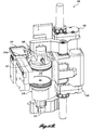
FIG. 3 is a perspective view showing the brew group for the beverage brewing system shown in FIG. 1;
FIG. 4 is a section view of the upper piston assembly shown in FIG. 3;
FIG. 5 is a section view of the lower piston assembly shown in FIG. 3;
FIGS. 6A, 6B, 6C, 6D, and 6E illustrate the brew group shown in FIG. 3 with the brewing chamber partially cut away, in various positions during the brewing cycle;
FIG. 7 illustrates the Coffee Brewing Control Chart;
FIG. 8 is a simplified block diagram of the brewing system shown in FIG. 1;
FIG. 9 illustrates graphically output data from an embodiment of the sensor array for the system shown in FIG. 9, that includes a TDS meter; and
FIG. 10 illustrates TDS curves from the sensor array of FIG. 9, showing curves for different coffee blends.
DETAILED DESCRIPTION
A particular embodiment of a brewing system in accordance with the present invention will now be described with reference to the figures, wherein like numbers indicate like parts. One or more of the present inventors is also an inventor for related and co-pending U.S. patent application Ser. No. 13/038,195, filed on Mar. 1, 2011, the disclosure of which is hereby incorporated by reference, in its entirety. FIG. 1 shows a perspective environmental view of a brewing system 100 in accordance with the present invention, having a hopper 102 disposed at a top of the system 100, and holding a carafe 90 in the dispensing area 104. A beverage selection and/or control panel 106 is shown generally above the dispensing area 104. It is contemplated that the hopper 102 may define a plurality of selectable compartments containing different brewable materials, for example different types or species of coffee beans. For example, the beverage selection panel 106 may give users the option to select a beverage size (e.g., 12, 16, or 20 ounces), among beverage choices (e.g., regular coffee, decaffeinated coffee, tea), and/or among flavoring or other additive options (e.g., creamer, sweetener, syrup flavors). The beverage selection panel 106 may also allow selection of a parameter of the brewed beverage (e.g., strength), and/or provide feedback regarding a quality of the brewed beverage.
The brewing system 100 may be suitable for brewing various brewable materials, such as ground coffee, tea, or the like. Although the following discussion may refer specifically to coffee brewing systems in places, it will be understood that the teachings of the present invention may similarly be applied to other brewing systems, including tea brewing systems.
FIG. 2 shows a top view of the brewing system 100 with the hopper 102 and certain other portions removed to expose internal components. In this embodiment the brewing system 100 includes a brew group controller 110, a power supply 112, an optional flavoring controller 116 and a water heater/reservoir 114. A grinder assembly 120 comprising two grinders 122, 124 is positioned to receive product, for example coffee beans, from the hopper 102. The brewable product from the grinder assembly 120 is expelled through a shared chute base 126, and a chute assembly 160.
A brew group 130, shown in more detail in FIG. 3, is plumbed to receive hot water from the reservoir 114 and configured to receive brewable product from the grinding assembly 120. The brew group 130 includes a cylindrical brewing chamber 132, currently formed with a cylindrical sleeve disposed in a block assembly 131. The brewing chamber 132 is positioned to receive coffee grounds from the grinder assembly 120. In a currently preferred embodiment the brewing chamber defines a cylindrical volume between 2 inches and 3.5 inches in diameter, and a height between 2.5 inches and 5.0 inches. However, the brew group including brewing chamber 132 may readily be scaled to other sizes.
A sliding arm assembly 134 is slidably disposed over the brewing chamber 132, and is configured to push spent grounds or other brewed material off of the block assembly 131. In this embodiment the sliding arm assembly 134 includes a C-shaped arm 134A that extends across the width of the brewing chamber 132. The lower transverse edges of the C-shaped arm 134A are beveled. The arm 134A is drivably attached to a drive arm subassembly 134B. The drive arm subassembly 134B is movable linearly by an actuator 134C such that the C-shaped arm 134A is controllably movable across the upper surface of the block assembly 131. In the current embodiment, the actuator 134C comprises an electric motor-driven worm gear system with a toothed belt (not shown) that drivably engages the drive arm subassembly 134B.
Although not required for the present invention, the actuator 134C, and the piston actuators discussed below, are preferably configured with encoders (not shown) to enable precise positioning of the various elements. In a current embodiment rotational sensors/encoders are provided on the drive motors, and linear sensors/encoders are provided on the drive shafts, to enable precise positional control. Exemplary sensors are Hall-effect sensors with magnets.
A novel aspect of the illustrated sliding arm assembly 134 is the flexibility of the assembly, which provides a very reliable and effective mechanism for removing spent coffee grounds, as discussed below. In particular, the drive arm subassembly 134B slides along an upper surface of the actuator 134C, and includes a spring-loaded hinged connection 134D. A portion of the drive arm subassembly 134B extends behind the C-shaped arm 134A and is connected thereto with a pivot 134E. The flexibility of the sliding arm assembly 134 provides a very reliable mechanism for scraping spent grounds from the block assembly 131.
The brew group 130 includes an upper piston assembly 140 that is pivotably attached to an upper support arm 142, which is attached to a first linear actuator 146. The upper piston assembly 140 is movable between a load position (shown in FIG. 3) and a brewing position wherein the upper piston assembly 140 sealingly engage the brewing chamber 132 from an open top end of the chamber 132. The upper piston assembly 140 includes a dispensing tube 141 that dispenses the brewed beverage. The upper piston assembly 140 is described in more detail below.
The brew group 130 further includes a lower piston assembly 150 that is pivotably attached to a lower support arm 152, which is pivotably attached to a second linear actuator 156. The lower piston assembly 150 is sized and configured to sealingly engage the brewing chamber 132 from an open bottom end of the chamber 132, and includes a water supply tube 151.
The first and second linear actuators 146, 156 further include a guide slot 135 and anti-rotation pin 136 (only one anti-rotation device 135, 136 visible in FIG. 3) to assure the corresponding piston moves only longitudinally.
FIG. 4 shows a cross section of the upper piston assembly 140. The upper piston assembly 140 defines a piston having a first piston member 140A that is configured to pivotably attach to the upper support arm 142, and includes a fixed lever arm 140B to facilitate pivoting the piston assembly 140. A channel 140C is defined from a front face of the first piston member 140A and extending to a lower face. The dispensing tube 141 is attached to the first piston member 140A with a half-cartridge fitting 140D and O-ring 140E, to fluidly and sealingly engage the channel 140C. A shaped recess 140F defines the lower face of the first piston member 140A.
A second piston member 143A is configured to nest with and engage the shaped recess 140F. A plurality of channels 143C extend through the second piston member 143A and fluidly engage the channel 140C in the first piston member 140A. An O-ring 143D is provided to seal the connection between the channel 140C and the plurality of channels 143C. The channels 140C, 143C therefore cooperatively define a plurality of fluid paths that extend from the lower face of the second piston member 143A to the dispensing tube 141. A perforated plate 148 is removably attached to the bottom face of the second piston member 143A with a fastener 149.
FIG. 5 shows a section view of the lower piston assembly 150. The lower piston assembly 150 includes a first piston member 150A configured to attach to the lower support arm 152. A channel 150C extends from a lower opening in the first piston member 150A to an upper face. The water supply tube 151 is attached to the first piston member 150A with a half-cartridge fitting 150D and O-ring 150E to fluidly and sealingly engage the channel 150C. A shaped recess 150F defines the lower face of the first piston member 150A.
A second piston member 153A is configured to nest with and engage the shaped recess 150F, and is removably attached thereto. A plurality of channels 153C extend through the second piston member 153A and fluidly engage the channel 150C in the first piston member 150A. An O-ring 153D is provided to seal the connection. The channels 150C, 153C therefore cooperatively define a plurality of flow paths that extend from the water supply tube 151 to the upper face of the second piston member 153A. A perforated plate 158 is removably attached to the second piston member 153A with a fastener 159.
The operation of the brew group 130 will now be described with reference to FIGS. 6A-6E, which illustrate the brew group 130 in isolation with a portion of the brew chamber 132 cut away, at various stations in the brew cycle. It is contemplated that the operation of the components of the brewing system 100 will be automatically controlled by the controller 110 and related systems, in response to the specific beverage request entered by a user from the beverage selection panel 106. Alternate means for entering a beverage request are also contemplated, for example using remote beverage entering system that is in signal communication with the brewing system 100, wirelessly (e.g., using RF, Bluetooth®, or the like) or using a card reading system, or the like.
FIG. 6A shows the brew group 130 in position to receive brewable material, for example ground coffee from the grinder assembly 130. The lower piston assembly 150 sealingly engages the brewing chamber 132, positioned near the lower end of the chamber 132 by the second linear actuator 156. The upper piston assembly 140 is positioned upwardly away from the brewing chamber 132 by the first linear actuator 146, and pivoted to the load position above. Brewable material from the grinder assembly 120 is received into the brewing chamber 132.
As illustrated in FIG. 6B, the upper piston assembly 140 is moved to the brewing position to sealingly engage an upper end of the brewing chamber 132. As the upper piston assembly 140 is moved downwardly, it pivots to a vertical orientation or brew position. It is contemplated that the vertical position of the lower piston assembly 150 may also be adjusted, for example to accommodate the selected beverage size. For example, if a “small” or “8-ounce” beverage was selected, the lower piston assembly 150 may be moved upwardly in the brewing chamber 132. Valves (not shown) are positioned to close liquid egress from the brewing chamber 132, and to fluidly connect the heated water reservoir 114 to the water supply tube 151. This initiates the flow of hot water through the lower piston assembly 150 and into the brewing chamber 132. Preferably the water pressure is maintained at a desired value to optimize brewing quality and/or speed. Preferably a nominal pressure in the range between 10 and 100 psig is maintained, and more preferably in the range of 20-60 psig for coffee or in the range of 10-50 psig for other brewable product such as tea.
When the desired amount of water and the desired pressure has been provided, the water supply may optionally be stopped to provide a desired time for brewing. It will be appreciated by persons of skill in the art that the pressurized brewing chamber 132, although lower in pressure than espresso makers, will nevertheless accelerate the brewing process as compared to prior art systems wherein the brewing chamber is not pressurized. In the current embodiment, the pressurized water supply from the heater/reservoir is regulated to provide a desired pressure. It is contemplated that the regulated pressure may be between 10 and 100 psig.
In a first embodiment or mode of operation of the system 100, the water flow is resumed (or maintained) and a dispensing valve (not shown) is opened to initiate the flow of brewed beverage through the upper piston assembly channels 140C, 143C to the dispensing tube 141, and then ultimately dispensed to the cup, carafe, or other container 90. In an alternative second mode of operation, the lower piston assembly 150 is moved upwardly through the brewing chamber 132, to cause the brewed liquid flow through the upper piston assembly 140 and to the dispensing tube 141.
FIG. 6C shows the brew group 130 wherein the lower piston assembly 150 has been moved upwardly part way through brewing chamber 132. In the first mode of operation, one or more valves (not shown) redirect the flow to a drain that is preferably plumbed into the system 100. In the second mode of operation, the upward movement of the lower piston assembly 150 dispenses the brewed liquid. In either case, the now spent brewed material is compressed between the upper piston assembly 140 and the lower piston assembly 150, such that a significant portion of the water is removed.
Referring now to FIG. 6D, the upper piston assembly 140 is moved upwardly to disengage from the brewing chamber 132 and pivots to the load position. The lower piston assembly 150 is moved upwardly such that the piston is approximately flush with the upper surface of the block assembly 131. The compressed spent grounds are therefore positioned to be removed, and the upper piston assembly 140 is moved out of the way of the sliding arm assembly 134.
FIG. 6E shows the sliding arm assembly 134 after sliding the C-shaped arm 134A over the brewing chamber 132 to remove the spent grounds. The system 100 may include an internal repository or chute for the spent grounds, or may be positioned over an external repository positioned to receive the grounds. The sliding arm assembly 134 may then be retracted, to return to the ready position shown in FIG. 6A.
From the above description, it will be appreciated that the currently preferred system provides for a liquid flow through the brewing chamber 132 that is initiated with heated water entering through the lower piston assembly 150 at the bottom of the brewing chamber 132, and brewed liquid exiting through the upper piston assembly 140. Although not preferred, it will be apparent to persons of skill in the art that with straightforward changes, the present invention may be practiced with the liquid flow proceeding in the opposite direction.
FIG. 7 shows a conventional Coffee Brewing Control Chart 60, attributed to Dr. E. E. Lockhart. The Control Chart 60 relates the soluble concentration or strength 62 in a brewed coffee liquid (a measure of the total dissolved solids in the liquid) to the soluble yield or extraction 64 from the coffee that generated the coffee liquid. Under this Control Chart, a coffee liquid having less than 1.15% soluble concentration will have a “Weak” flavor, and coffee having greater than 1.35% soluble concentration will have a “Strong” flavor. If less than 18% of the solubles are extracted from the brewed coffee then the flavor of the coffee liquid will be “Underdeveloped,” but if more than 22% of the solubles are extracted from the brewed coffee then the flavor will be “Bitter.” Therefore, the Control Chart defines an “Ideal” flavor region within these bounds. The diagonal curves indicate particular “brewing formulas,” i.e., the ratio of ground coffee (e.g., in ounces) to water brewed (e.g., in gallons). The line 66, for example, corresponds to a ratio of 7.5 oz of coffee to one gallon of water. Lines to the right and below line 66 indicate progressively lower coffee-to-water ratio formulae, and lines to the left and above line 66 indicate progressively higher coffee-to-water ratio formulae.
Therefore, if the brewing formula is known, and the total dissolved solids (“TDS”) in the brewed liquid is known, the beverage location on the on the Control Chart 60 can be precisely determined. It should be appreciated that the Control Chart provides a guideline for producing a high quality coffee beverage, and that the preferred coffee liquid strength and extraction parameters are not necessarily in the center of the “Ideal” box in the Control Chart. In practice, it may be desirable to determine the strength and extraction parameters that are optimal for a particular coffee blend, e.g., a preferred location on the Control Chart 60, and then to control the brewing cycle parameters to target those optimal values. It will also be appreciated that personal preferences may differ. For example, one person may prefer a beverage that is nearer the top of the “Ideal” box, whereas another user may prefer a beverage relatively lower in the “Ideal” box.
It will be appreciated, as alluded to above, that the strength and extraction of a brewed beverage may be controlled or modified through different parameters in the brewing process, for example by adjusting one or more of (i) the coffee to water formula, (ii) the brewing time, (iii) the water temperature, (iv) the water pressure, (v) the grind size, etc. The optimal strength and extraction targets will also generally be dependent on the particular blend or brand of coffee. Although the Control Chart 60 is specifically directed to brewing coffee, it is contemplated that very similar methods may be used to characterize the quality of other brewed liquids, for example particular teas.
One difficulty in using the Control Chart 60 in an automated brewing system such as the system 100, is that the strength or TDS in the brewed liquid in the Control Chart is the final or batch value at the end of the brewing cycle. This batch value is typically inconvenient or difficult to obtain.
FIG. 8 illustrates a simplified block diagram of the brewing system 100, showing the hopper 102, water reservoir 114, grinder assembly 120, and brew group 130 described above. An inline sensor or sensor array 200 is fluidly connected to the dispensing tube 141, such that the brewed liquid flows by or through the sensor array 200. (As used herein, a sensor array may include a single sensor or a plurality of sensors.) The sensor array 200 measures properties of the brewed liquid at a particular inline location along the flow path, as the brewed liquid flows from the brew group 130 towards the dispensing container 90. The sensor array 200, therefore, will produce a time-dependent output showing the measured property of the liquid stream as it flows by the sensor array 200. In a current embodiment the sensor array 200 is located along the fluid path shortly downstream of the brew group 130, although other locations are also contemplated, including at the brewed liquid dispensing station.
The sensing array 200 provides specific data regarding qualities of the brewed liquid that may be used, for example, to monitor the quality of the beverage. The data provides feedback that may be used to initially configure particular settings of the system 100, and/or to monitor each brew to provide feedback that may be used to adjust brew parameters to maintain optimal product quality.
A controller 210, which in this embodiment includes a programmable processor 212, a memory module 214, a plurality of data input ports 216, a control signal generator 218, and a program interface module 220, is in signal communication with the sensor array 200. The controller 210 may additionally be in signal communication with other components of the brewing system, as indicted by the dashed lines in FIG. 8.
The sensor array 200 produces unsteady or time-dependent signals preferably over the entire period that the brewed liquid passes through or by the sensor array 200. The signals represent a measured property of the brewed liquid. The unsteady signals are transmitted to the controller 210. Additional data may also be transmitted to the controller 210, for example data from other system components such as the grinder 120, water supply 114, etc. For example, temperature sensors (e.g., a brewing chamber temperature thermocouple) may provide information that is useful for interpreting data from the sensor array 200. Similarly, the current grinder setting may be transmitted to the controller 210.
In a particular embodiment external data may also be provided to the controller 210. For example, the coffee blend and/or brand may be provided using a reader (e.g., barcode or RF system, etc.) that obtains data from coffee packaging, and transmits the data to the controller 210.
The controller 210 processes the received data, and uses the data to generate control signals to adjust one or more brewing parameters to achieve a desired and consistent brew quality. For example, the grind time (i.e., quantity of ground coffee), grind size, hot water temperature, brewing pressure, and brew time are all potentially adjustable parameters.
The controller 210 may further include a communications port 94, for example with wired or wireless connection to a network (not shown), such that sensor array 200 data and related information (e.g., TDS/strength, brewing formula, extraction, etc.) and the state of various brew parameters may be reported out. For example, the quality of each brewed beverage (e.g., strength and extraction) may be reported and recorded, to verify that the desired quality is consistently maintained in the “gold cup” box of FIG. 7.
FIG. 9 illustrates graphically output data from an embodiment of the sensor array 200 that includes a TDS meter, for example a conductivity meter calibrated to indicate the level of total dissolved solids in the fluid stream. In this example the individual curves relate the measured TDS 302 as a function of time 304 as measured by the sensor array 200 during the beverage dispensing cycle. The curves show the measured results for different brewing formulas, wherein the quantity of ground coffee deposited into the brewing chamber 132 was varied. In this exemplary graph, curve 306 shows the unsteady TDS measurement using 14.9 g of coffee, curve 308 shows the unsteady TDS measurement using 18.5 g of coffee, curve 310 shows the unsteady TDS measurement using 22.5 g of coffee; curve 312 shows the unsteady TDS measurement using 26.0 g of coffee, and curve 314 shows the unsteady TDS measurement using 29.7 g of coffee, all with a predetermined amount of water.
It will be appreciated that the batch value of the TDS in the brewed liquid can be determined by suitably integrating the flow-weighted measured TDS over time. For example, if the flow rate is constant during the dispensing cycle measurement, then the batch TDS will be the average of the measured TDS during the dispensing cycle. It is contemplated that the sensor array 200 may further include a temperature sensor. The temperature can affect the measured TDS when a conductivity sensor is used, and therefore for improved accuracy the conductivity measurement for TDS may be adjusted to account for temperature.
It will also be appreciated that the shape of the time-dependent curves, or “coffee signature” data, provides additional information regarding the coffee and the brewed coffee liquid. The shape of the curves provides information regarding the rate that the solids are dissolved from the coffee matrix. This coffee signature data may be used to guide which of the various parameters in the brewing cycle should be adjusted to improve the quality of the brewed liquid. For example, in order to move the system towards a desired point on the Control Chart 60, the system may elect to either add more coffee to the brewing formula, or may adjust to a finer grind of the coffee. An automated optimization strategy may be readily determined heuristically and then programmed into the controller 210 for subsequent brews. It will be appreciated that the heuristic formulation may be developed independently for different coffee blends, for example.
It is also contemplated that the coffee signature data may be used to determine the specific type, blend, or brand of coffee present in the system 100. For example, data from the sensing array 200 may be used to distinguish between different coffee bean species such as coffea Arabica (commonly referred to as “Arabica”) and coffea canephora (commonly referred to as “Robusta”), and to identify subvarieties, types, and particular blends of coffee. FIG. 10 illustrates TDS curves from the sensor array 200, wherein curve 320 is for one coffee blend, and curve 322 is for another different coffee blend. The brewing parameters and brewing formula were the same for both curves 320, 322. The data from the sensing array 200 may therefore be used to identify the blend of coffee being used. Identifying the blend of coffee may further be used to customize and optimize the brewing parameters for the particular coffee blend (for subsequent brew cycles).
In a particular embodiment, the memory module 214 is provided with a database of coffee signature curves, or family of curves, and the processor 212 compares the measured coffee signature data with the database of curves, to identify the coffee blend, and/or to determine if the coffee blend is in a particular group or family.
In addition, identifying the coffee blend may be important to ensuring that the intended blend or brand of coffee is used in a particular brewer apparatus. In some business models for providing coffee in commercial settings, for example, a coffee vendor may provide the brewing equipment at little or no cost, relying on the sales of consumables to make the business model work. The ability to identify that the coffee being used in the brewing equipment is from the vendor is important in such situations.
The time-dependent data may also be used to identify and provide diagnostic information if maintenance is required. For example, the time-dependent data may indicate that the ground coffee is not achieving the desired particle size, indicating maintenance or adjustment of the grinders may be needed.
As noted above, the taste preferences of users will vary. Most users will prefer a brewed coffee, for example, to be within the “Ideal” box in FIG. 7, but the preferred location within that box may be different from person to person. It is contemplated, as indicated in FIG. 8, that the user may input 92 a desired beverage from the control panel 106 of the brewing system. The input may include a mechanism for selecting within a range a desired brewing parameter. For example, a user may select a level of “strength,” to adjust the target TDS in the brewed liquid. In another example, the control panel 106 may display a chart such at the Control Chart 60 (FIG. 7) and allow the user to select a two-dimensional location on the Control Chart 60 for a brewed coffee beverage. The controller 210 will then take the user input, and adjust the brewing parameters to achieve the target quality. Because the sensor array 200 is disposed inline with the brewed liquid, the brewing system 100 may also be configured to report or display to the user (e.g., on the control panel 106) the measured results, for example displaying measured TDS and/or temperature, or displaying the location on the Control Chart 60 based on the sensor array output and the brewing parameters.
The disclosed apparatus and method is new and unique in that it describes, for a beverage dispensing system, a method and apparatus to sense and measure the continually varying time-based signature of physical characteristics in the brewed liquid stream. The resulting signature provides: a) a means for predicting the end-item in-the-cup beverage quality; b) a means for monitoring in-process beverage production and means of adjustment, or correction of beverage quality; c) a means for monitoring system 100 performance and maintenance needs; d) a means for protecting brand integrity, such as with a coffee roaster or gourmet tea producer; and e) a means for providing system 100 calibration, either manually, or automatically.
It is contemplated that one or more visible and non-visible light wavelength sensors, along with temperature sensors in several locations may be used to provide both means for monitoring beverage properties, e.g., temperature. In particular, one or more near-infrared sensors have been found useful. Other suitable sensors contemplated include acoustic sensors.
Multiple sensors of the same type, for example, two near-infrared sensors, can be employed in the array to provide redundancy and improved signal-to-noise characteristics. Additionally, if multiple visible light sensors are employed, they may, or may not, be of the same wavelength, if it is desired to observe different brew-stream characteristics. In its current embodiment, temperature sensors are also placed to monitor the equipment temperatures, such as the brew chamber 132.
For example, the present method may include the following steps:
1) The brewed liquid stream is configured to pass through, or by, the sensor array 200.
2) The system electronics capture the output of the sensor array 200.
3) The time-based signature is then analyzed and/or correlated, via signature comparison, numerical algorithm, look-up table, or the like, to known, or desired, beverage quality standards (such as a refractometer or total dissolved solids) for the end-batch.
Additional features and advantages of particular embodiments of the present invention include:
a. Prediction of in-the-cup beverage quality to the consumer. The brewing system 100 provides a means for verifying that a consistent “Gold Cup” standard beverage or the like has been produced, and may be configured to transmit results from the sensor array 200 to alert others if maintenance is required, for example.
b. Enables in-process monitoring and means of adjustment to maintain in-cup-beverage quality. Comparing the signature and/or analysis results and making adjustments, such as adding more ground coffee, or adjusting coffee grinders 130, temperature, etc., to obtain the “Gold Cup” coffee beverage consistently.
c. Enables pro-active means for establishing system 100 maintenance needs.
d. Protection of Brand Integrity. A high-value brand utilizing the present system 100, with their various coffee roasts, each having a unique brew-stream signature. The system 100 will be able to determine if other brands, or lesser-quality coffee products were substituted, and appropriate action could take place, such as shutting down of the system 100.
e. Enable self-calibration of system 100 when different product, such as different coffee roast, or blend, is introduced.
While illustrative embodiments have been illustrated and described, it will be appreciated that various changes can be made therein without departing from the spirit and scope of the invention.

Claims (23)

The embodiments of the invention in which an exclusive property or privilege is claimed are defined as follows:
1. A brewing system comprising:
a hopper configured to dispense brewable product;
a reservoir configured to dispense heated water;
a brewing chamber that receives brewable product from the hopper, and receives heated water from the reservoir, wherein the brewing chamber is configured to produce a brewed liquid from the received brewable product and heated water and to dispense the brewed liquid in a fluid stream;
a controller that controls the operation of the brewing system, the controller comprising a processor, an input signal port, an output signal port, and a memory module;
a sensor positioned to intercept the fluid stream, and operable to measure a property of the brewed liquid at a fixed location as the brewed liquid flows by the sensor, wherein the sensor generates time-dependent data corresponding to the measured property, and communicates the time-dependent data to the controller;
wherein the controller uses the time-dependent data to control the amount of brewable product received by the brewing chamber.
2. The brewing system of claim 1, wherein the controller uses the time-dependent data to identify the brewable product.
3. The brewing system of claim 1, wherein the controller uses the time-dependent data to identify if there is a need to service the brewing system.
4. The brewing system of claim 1, wherein brewable product comprises coffee and wherein the system further comprises a coffee grinder configured to grind coffee from the hopper.
5. The brewing system of claim 4, wherein the sensor measures total dissolved solids in the brewed liquid.
6. The brewing system of claim 5, further comprising means for displaying the measured total dissolved solids in the brewed liquid.
7. The brewing system of claim 4, wherein the controller is in signal communication with the grinder, and further wherein the controller uses the time-dependent data to control the operation of the grinder.
8. The brewing system of claim 1, wherein the sensor comprises a conductivity sensor.
9. The brewing system of claim 1, wherein the brewing chamber comprises a cylindrical chamber and is part of a brew group further comprising a lower piston that is attached to a first linear actuator and sealably engages an open lower end of the brewing chamber, an upper piston assembly that is attached to a second linear actuator and sealably and releasably engages an open upper end of the brewing chamber, and a sliding arm assembly that is attached to a third linear actuator and is operable to slide over the open upper end of the brewing chamber.
10. The brewing system of claim 1, wherein the controller further uses the time-dependent data to identify the brand of the brewable product.
11. The brewing system of claim 4, wherein the controller further uses the time-dependent data to identify the brand of the coffee.
12. The brewing system of claim 1, further comprising means for displaying a quality of the brewed beverage based on property of the brewed liquid measured by the sensor.
13. A method for producing a brewable beverage in a brewing system having a controller and a sensor, the method comprising:
grinding coffee beans with a grinder to produce a brewable product;
providing a quantity of the brewable product to a brewing chamber;
providing a quantity of heated water to the brewing chamber;
permitting the brewable product to brew in the heated water in the brewing chamber to produce a brewed liquid;
forcing at least a portion of the brewed liquid from the brewing chamber in a fluid stream;
measuring a property of the brewed liquid with the sensor at a fixed location as the fluid stream flows by the fixed location, to generate a time-dependent data set for the fluid stream corresponding to the measured property, the measured property comprising the total dissolved solids in the brewed liquid; and
using the time-dependent data set to control the operation of the grinder.
14. The method of claim 13, wherein the time-dependent data set is used by the controller to evaluate a quality of the dispensed brewed liquid.
15. The method of claim 13, wherein the time-dependent data set is used by the controller to control at least one brewing parameter of the brewing system.
16. The method of claim 13, wherein the time-dependent data set is used by the controller identify the brand of the brewable product.
17. The method of claim 13, wherein the time-dependent data set is used by the controller to identify if the brewing system is in need of maintenance.
18. The method of claim 13, wherein the sensor is a conductivity meter.
19. The method of claim 13, wherein the brewing chamber is a part of a brew group that further comprises a lower piston that is attached to a first linear actuator and sealably engages an open lower end of the brewing chamber, an upper piston assembly that is attached to a second linear actuator and sealably and releasably engages an open upper end of the brewing chamber, and a sliding arm assembly that is attached to a third linear actuator and is operable to slide over the open upper end of the brewing chamber.
20. A brewing system comprising:
a hopper configured to dispense coffee beans;
a coffee grinder configured to receive and grind coffee beans from the hopper to produce a brewable product;
a reservoir configured to dispense heated water;
a brewing chamber configured to receive the brewable product from the grinder, and to receive heated water from the reservoir, wherein the brewing chamber is configured to produce a brewed liquid from the received brewable product and heated water and to dispense the brewed liquid in a fluid stream;
a controller that controls the operation of the brewing system, the controller comprising a processor, an input signal port, an output signal port, and a memory module;
a sensor positioned to intercept the fluid stream, and operable to measure a property of the brewed liquid at a fixed location as the brewed liquid flows by the sensor, wherein the sensor generates time-dependent data corresponding to the measured property, and communicates the time-dependent data to the controller;
wherein the controller is in signal communication with the grinder, and further wherein the controller uses the time-dependent data to control the operation of the grinder.
21. A brewing system comprising:
a hopper configured to dispense brewable product;
a reservoir configured to dispense heated water;
a brewing chamber that receives brewable product from the hopper, and receives heated water from the reservoir, wherein the brewing chamber is configured to produce a brewed liquid from the received brewable product and heated water and to dispense the brewed liquid in a fluid stream;
a controller that controls the operation of the brewing system, the controller comprising a processor, an input signal port, an output signal port, and a memory module;
a sensor positioned to intercept the fluid stream, and operable to measure a property of the brewed liquid at a fixed location as the brewed liquid flows by the sensor, wherein the sensor generates time-dependent data corresponding to the measured property, and communicates the time-dependent data to the controller;
wherein the brewing chamber comprises a cylindrical chamber and is part of a brew group further comprising a lower piston that is attached to a first linear actuator and sealably engages an open lower end of the brewing chamber, an upper piston assembly that is attached to a second linear actuator and sealably and releasably engages an open upper end of the brewing chamber, and a sliding arm assembly that is attached to a third linear actuator and is operable to slide over the open upper end of the brewing chamber.
22. A method for producing a brewable beverage comprising:
providing a quantity of brewable product to a brewing chamber;
providing a quantity of heated water to the brewing chamber;
permitting the brewable product to brew in the heated water in the brewing chamber to produce a brewed liquid;
forcing at least a portion of the brewed liquid from the brewing chamber in a fluid stream;
measuring a property of the brewed liquid at a fixed location as the fluid stream flows by the fixed location, to generate a time-dependent data set for the fluid stream corresponding to the measured property;
wherein the brewing chamber is a part of a brew group that further comprises a lower piston that is attached to a first linear actuator and sealably engages an open lower end of the brewing chamber, an upper piston assembly that is attached to a second linear actuator and sealably and releasably engages an open upper end of the brewing chamber, and a sliding arm assembly that is attached to a third linear actuator and is operable to slide over the open upper end of the brewing chamber.
23. A method for producing a brewable beverage comprising:
providing a quantity of brewable product to a brewing chamber;
providing a quantity of heated water to the brewing chamber;
permitting the brewable product to brew in the heated water in the brewing chamber to produce a brewed liquid;
forcing at least a portion of the brewed liquid from the brewing chamber in a fluid stream;
measuring a property of the brewed liquid at a fixed location as the fluid stream flows by the fixed location, to generate a time-dependent data set for the fluid stream corresponding to the measured property;
using the time-dependent data set to control the amount of brewable product that is provided to the brewing chamber.
US13/050,852 2010-03-01 2011-03-17 Method and apparatus for controlling brewed beverage quality Active 2031-08-11 US8623441B2 (en)

Priority Applications (2)

Application Number Priority Date Filing Date Title
US13/050,852 US8623441B2 (en) 2010-03-01 2011-03-17 Method and apparatus for controlling brewed beverage quality
US13/086,257 US8616116B2 (en) 2010-03-01 2011-04-13 High speed brewing apparatus

Applications Claiming Priority (4)

Application Number Priority Date Filing Date Title
US30940110P 2010-03-01 2010-03-01
US31584710P 2010-03-19 2010-03-19
US13/038,195 US8247010B2 (en) 2010-03-01 2011-03-01 Accelerated low pressure brewer and a method for making a beverage
US13/050,852 US8623441B2 (en) 2010-03-01 2011-03-17 Method and apparatus for controlling brewed beverage quality

Related Parent Applications (1)

Application Number Title Priority Date Filing Date
US13/038,195 Continuation-In-Part US8247010B2 (en) 2010-03-01 2011-03-01 Accelerated low pressure brewer and a method for making a beverage

Related Child Applications (1)

Application Number Title Priority Date Filing Date
US13/086,257 Continuation-In-Part US8616116B2 (en) 2010-03-01 2011-04-13 High speed brewing apparatus

Publications (2)

Publication Number Publication Date
US20110212229A1 US20110212229A1 (en) 2011-09-01
US8623441B2 true US8623441B2 (en) 2014-01-07

Family

ID=44505423

Family Applications (1)

Application Number Title Priority Date Filing Date
US13/050,852 Active 2031-08-11 US8623441B2 (en) 2010-03-01 2011-03-17 Method and apparatus for controlling brewed beverage quality

Country Status (1)

Country Link
US (1) US8623441B2 (en)

Cited By (9)

* Cited by examiner, † Cited by third party
Publication number Priority date Publication date Assignee Title
US20140102308A1 (en) * 2012-10-12 2014-04-17 Christian KOESTER Brewing unit for a coffee machine
US20140322397A1 (en) * 2013-04-27 2014-10-30 David F. Mamo Aseptic hot-brewed packaged coffee or espresso beverage
US20150216355A1 (en) * 2012-08-16 2015-08-06 Gideon Duvall Device and system for brewing infused beverages
US20170364989A1 (en) * 2016-06-15 2017-12-21 Libation Liberation, Inc. Systems and methods for categorizing, searching, and retrieving information relating to products based on profiles
US9930987B2 (en) 2013-11-20 2018-04-03 Starbucks Corporation Apparatuses, systems, and methods for brewing a beverage
US10314426B2 (en) 2011-11-23 2019-06-11 Starbucks Corporation Apparatus, systems, and methods for brewing a beverage
CN110151016A (en) * 2019-05-06 2019-08-23 深圳市西啡科技有限公司 A kind of capsule cooking machine
US10470601B2 (en) * 2015-11-24 2019-11-12 Guen Lung Tuan Co., Ltd. Tea drink preparation method
US11067498B2 (en) * 2018-03-06 2021-07-20 Vorwerk & Co. Interholding Gmbh Food preparation and analyzing device

Families Citing this family (23)

* Cited by examiner, † Cited by third party
Publication number Priority date Publication date Assignee Title
US20110185907A1 (en) * 2009-01-13 2011-08-04 De'longhi S.P.A. Apparatus for producing a coffee beverage and method of filling the receptacle of said apparatus
EP2542127B1 (en) * 2010-03-01 2018-05-30 Concordia Coffee Company Inc. Accelerated low pressure brewer
US8616116B2 (en) * 2010-03-01 2013-12-31 Concordia Coffee Company, Inc. High speed brewing apparatus
US8639374B2 (en) 2010-11-05 2014-01-28 The Coca-Cola Company Method, apparatus and system for regulating a product attribute profile
US20120114814A1 (en) * 2010-11-05 2012-05-10 The Coca-Cola Company Method of beverage production, apparatus and system
ITRM20110458A1 (en) * 2011-09-05 2013-03-06 Iacobucci Hf Electronics S P A POD HOLDER DEVICE FOR BEVERAGE DISPENSING MACHINE
US20130098249A1 (en) * 2011-10-14 2013-04-25 Michael Fidler Coffee Apparatus
WO2013072798A1 (en) * 2011-11-16 2013-05-23 Koninklijke Philips Electronics N.V. Beverage making apparatus and method
PT2840946T (en) * 2012-04-24 2017-06-06 Nestec Sa User-interface for beverage preparaton machines
CN103230225B (en) * 2013-04-15 2015-04-22 广东新宝电器股份有限公司 Coffee machine with automatic bag dropping function
CN110501303A (en) * 2013-05-27 2019-11-26 皇家飞利浦有限公司 The machine and method for sensing the device and method of the characteristic of food materials and infusing coffee
US10362894B2 (en) * 2013-12-20 2019-07-30 Gerald S. Fain Globally networked on-demand coffee blending and brewing system
WO2015131128A2 (en) * 2014-02-27 2015-09-03 Bkon Llc System and method of brewing beverages using geo-location based brewing parameters
US20160324363A1 (en) * 2015-01-21 2016-11-10 Ross Cohen Novel Device for Maximizing the Production of and Preservation of 2-furfurylthiol in Frozen Coffee Cubes
US20160235249A1 (en) * 2015-02-13 2016-08-18 Michael Teahan Coffee Grinder Remote Control and Data Collection Device
US20170119195A1 (en) 2015-10-22 2017-05-04 Auroma Brewing Company System and method for controlling the brew process of a coffee maker
US20170119200A1 (en) * 2016-01-19 2017-05-04 Anthony David Bressi Automated beverage and fragrance synthesizers
JP6681126B2 (en) * 2016-04-25 2020-04-15 ギデオン ドゥボールDUVALL, Gideon Control system and method for brewing a brewed beverage
WO2018044845A1 (en) 2016-08-29 2018-03-08 Auroma Brewing Company System and method for automated coffee grind refinement
US20190082881A1 (en) * 2017-03-17 2019-03-21 Mere Coffee, Inc. System and method for brewing a cup of coffee
DE102018205153A1 (en) * 2018-04-05 2019-10-10 Wmf Group Gmbh Beverage maker and method for operating a beverage maker
DE102018116306B4 (en) * 2018-07-05 2023-01-05 Melitta Professional Coffee Solutions GmbH & Co. KG Process for producing caffeinated hot beverages, in particular coffee beverages, with a device for producing a caffeinated hot beverage
DE102018117089A1 (en) * 2018-07-16 2020-01-16 Miele & Cie. Kg Device and method for operating a vending machine and vending machine

Citations (99)

* Cited by examiner, † Cited by third party
Publication number Priority date Publication date Assignee Title
US332199A (en) 1885-12-08 Drier
US2658645A (en) 1950-01-31 1953-11-10 Edwin M Thomas Dispensing machine for beverages having plural ingredients
US2733731A (en) 1956-02-07 Turak
US3086446A (en) * 1960-10-06 1963-04-23 Rock Ola Mfg Corp Coffee brewing apparatus
US3249196A (en) 1963-09-25 1966-05-03 Fisher & Ludlow Ltd Coin freed vending machines
US3385569A (en) 1967-01-11 1968-05-28 Rock Ola Mfg Corp Mixing apparatus for beverage
US3482989A (en) * 1965-09-17 1969-12-09 Cornelius Co Method for brewing coffee beverage
US3671273A (en) 1968-05-20 1972-06-20 Alec C Gunter Apparatus for preparing a cocoa concentrate
US3920299A (en) 1974-08-05 1975-11-18 Miller Herman Inc Laboratory module system
USD253953S (en) 1977-06-02 1980-01-15 Restaurant Technology, Inc. Sundae machine
US4211342A (en) 1978-02-22 1980-07-08 Ara Services, Inc. Combination hot and cold drink machine
USD264214S (en) 1979-11-19 1982-05-04 Tyler Refrigeration Corporation Mobile beverage cooling and dispensing unit
US4438683A (en) 1982-02-26 1984-03-27 Prize Frize, Inc. Apparatus for dispensing individual orders of a hot food product and components usable therewith
USD288267S (en) 1984-02-03 1987-02-17 Meyer Ronald K Automated bartender wall unit
US4649809A (en) 1984-08-31 1987-03-17 Sanden Corporation Beverage vending machine
USD289129S (en) 1984-06-18 1987-04-07 Fountain Industries, Inc. Hot beverage server
US4715274A (en) 1985-01-31 1987-12-29 Spidem S.R.L. Emulsifier unit particularly for emulsifying steam and milk to prepare cappuccinos and the like beverages
US4797296A (en) 1986-03-08 1989-01-10 Cafina Ag Piston-cylinder-assembly for a coffee brewing apparatus and a method of its operation
US4815633A (en) 1983-04-05 1989-03-28 Sanden Corporation Automatic coffee vending machine being able to serve a straight coffee and a blended coffee selectively
USD302221S (en) 1986-04-14 1989-07-18 Royston Corporation Foodservice counter with sneeze guard
US4873916A (en) 1987-02-04 1989-10-17 De Erven De Weduwe J. Van Nelle B.V. Method and device for the preparation of coffee
USD308686S (en) 1988-01-26 1990-06-19 TYS, Inc. Frozen yogurt dispensing bar
US4974500A (en) 1989-09-29 1990-12-04 Boyd Coffee Company Hot beverage preparation and dispensing cart
USD313724S (en) 1988-02-11 1991-01-15 Gaggia Espanola, S.A. Coffee maker
JPH0339114A (en) * 1989-07-05 1991-02-20 Matsushita Electric Ind Co Ltd Coffee maker
USD316794S (en) 1988-11-16 1991-05-14 Cafina Ag Coffee machine
US5033645A (en) 1987-10-13 1991-07-23 Abc/Sebrn Tech Corp. Carbonation system for soft drink dispenser
USD318973S (en) 1987-12-01 1991-08-13 Robert Kurps Stiftung & Co. KG. Combined coffee and espresso making machine
US5056686A (en) 1989-06-27 1991-10-15 Nutri-Fruit, Inc. Beverage dispensing system
US5116632A (en) 1988-12-22 1992-05-26 Miller Harold F Brewing and dispensing system and method for iced tea
USD329857S (en) 1989-12-26 1992-09-29 TYS, Inc. Yogurt bar
EP0508703A2 (en) 1991-04-10 1992-10-14 Bunn-O-Matic Corporation Automatic brewer
US5207148A (en) 1990-06-25 1993-05-04 Caffe Acorto, Inc. Automated milk inclusive coffee apparatus
JPH05120545A (en) * 1991-06-13 1993-05-18 Fuji Electric Co Ltd Coffee liquid concentration measuring method and coffee automatic vending machine
USD337475S (en) 1990-12-12 1993-07-20 Robert Krups Gmbh & Co. Kg Espresso making machine
US5230277A (en) 1991-01-25 1993-07-27 Ricerca Elettromeccanica S.R.L. Device for making coffee
US5233915A (en) 1991-04-19 1993-08-10 Spidem S.R.L. Steam injection nozzle for beverages
USD340611S (en) 1991-07-22 1993-10-26 Hoover Billy H Coffee dispenser
US5255593A (en) * 1991-04-10 1993-10-26 Bunn-O-Matic Corporation Automatic brewer
US5303639A (en) 1991-04-10 1994-04-19 Bunn-O-Matic Corporation Automatic brewer
US5309822A (en) 1991-10-11 1994-05-10 Hgz Maschinenbau Ag Automatic coffee machine
US5316781A (en) 1991-07-30 1994-05-31 Sintra Holding Ag Brewing device for a coffee machine and method of producing coffee
USD347755S (en) 1992-08-31 1994-06-14 Houston William V Vending display bar
US5341957A (en) 1993-01-08 1994-08-30 Sizemore Sean S Cup-type vending system and method for dispensing beverages
US5344050A (en) 1993-04-01 1994-09-06 Unidynamics Corporation Moisture reduction system for an automatic vending machine
US5353692A (en) 1993-09-29 1994-10-11 Unidynamics Corporation Hot beverage brewing apparatus
US5393540A (en) 1991-04-10 1995-02-28 Bunn-O-Matic Corporation Automatic beverage brewing method
USD357062S (en) 1992-03-25 1995-04-04 Schreiner Edward J Combined multiple use and preparation unit
US5423245A (en) 1994-04-13 1995-06-13 Bunn-O-Matic Corporation Milk foaming device
USD365490S (en) 1994-09-30 1995-12-26 Caffe Acorto, Inc. Automatic coffee machine
US5579678A (en) 1995-10-06 1996-12-03 Royal Cup, Inc. Apparatus for automatically sweetening tea
US5650186A (en) 1993-06-07 1997-07-22 Annoni; Faust Hot beverage brewing and dispensing apparatus and method
USD395975S (en) 1995-12-29 1998-07-14 Gaggia Espanola, S.A. Coffee machine
USD396987S (en) 1995-10-18 1998-08-18 Robert Krups Gmbh & Co. Kg Espresso maker
USD398432S (en) 1997-03-10 1998-09-15 Vengo 2000, Inc. Transportable vending cart
US5911810A (en) 1997-06-23 1999-06-15 Sanden Corp. Coffee brewing apparatus and method of brewing coffee by the apparatus
US5941163A (en) 1996-04-13 1999-08-24 Kwangju Electronics Co., Ltd Brewed coffee vending machine
USD413757S (en) 1998-08-03 1999-09-14 Gaggia Espanola, S.A. Coffee machine
USD414371S (en) 1997-03-24 1999-09-28 Robert Krups Gmbh & Co Kg Electric espresso making machine
USD417118S (en) 1998-10-30 1999-11-30 Acorto, Inc. Automatic espresso machine
US6019032A (en) 1998-10-30 2000-02-01 Acorto, Inc. Automated espresso and milk aeration apparatus and method
US6098524A (en) 1998-09-16 2000-08-08 Crane Co. Hot beverage vending machine
US6135169A (en) 1998-04-15 2000-10-24 Ducale Macchine Da Caffe' Di Sandei Ugo E C. S.N.C. Automatic cupped drinks dispenser
US6182555B1 (en) 1999-04-07 2001-02-06 Red River Tea Company Apparatus and methods for brewing and dispensing beverages
US6205909B1 (en) 1997-09-05 2001-03-27 Moulinex S.A. Brewing unit for automatic beverage dispensers comprising in particular a boiler
JP2001106261A (en) * 1999-10-05 2001-04-17 Sanyo Electric Co Ltd Storage container for raw material
US6237811B1 (en) 1999-10-08 2001-05-29 Bunn-O-Matic Corporation Programmable dispenser
US6240829B1 (en) 1999-02-12 2001-06-05 Pepsico. Inc. Tea or non-carbonated drink dispenser
USD443398S1 (en) 2000-05-12 2001-06-05 Floyd E. Mount Beverage cart
US6253667B1 (en) 1996-04-24 2001-07-03 Sara Lee/De N.V. Assembly for preparing hot and frothed milk
USD445292S1 (en) 2000-07-14 2001-07-24 Rancilio Macchine per Caffe′ S.P.A. Coffee machine
USD449198S1 (en) 2000-02-02 2001-10-16 Societe Des Produits Nestle S.A. Coffee machine
USD455596S1 (en) 2000-10-13 2002-04-16 Wmf Wuerttembergische Metallwarenfabrik Ag Coffee machine
US6419120B1 (en) 2000-07-12 2002-07-16 Bertone Holdings Inc. Multi-flavored hot beverage dispenser
US20030145736A1 (en) 2002-02-07 2003-08-07 Green Charles Bradley Coffee and tea dispenser
US6634280B2 (en) 2000-05-31 2003-10-21 Rancilio Macchine Per Caffe' S.P.A. Coffee making machine
USD481901S1 (en) 2002-01-28 2003-11-11 BSH Bosch und Siemens Hausgeräte GmbH Automatic coffee maker
USD486346S1 (en) 2002-10-01 2004-02-10 Jura Elektroapparate Ag Coffee maker
US6726950B2 (en) 2002-09-12 2004-04-27 Tadashi Yuzawa Method for producing a coffee beverage
US20040168465A1 (en) 2001-09-06 2004-09-02 Manitowoc Foodservice Companies, Inc. Low volume beverage dispenser
USD495915S1 (en) 2003-05-08 2004-09-14 Societe Des Produits Nestle S.A. Coffee machine
US20050172833A1 (en) 2004-02-06 2005-08-11 Niro-Plan Ag Device for producing milk foam
US6994231B2 (en) 2002-05-14 2006-02-07 Jones Charles H System and method for dispensing beverages
US20060034987A1 (en) 2004-08-12 2006-02-16 Thakur Beli R Method and apparatus for consumable powder reconstitution and frothing
US7021206B2 (en) 2002-06-18 2006-04-04 Eckenhausen Roland B Hot dairy-based beverage dispenser
US7066079B2 (en) 2004-05-14 2006-06-27 Hgz Maschinenbau Ag Automatic coffee machine
USD527939S1 (en) 2000-11-16 2006-09-12 Marathon Petroleum Company Llc Fountain beverage dispenser
US7147131B2 (en) 2003-12-05 2006-12-12 Nestec S.A. Method and system for dispensing hot and cold beverages from liquid concentrates
USD536204S1 (en) 2005-04-13 2007-02-06 Isett David E Drink dispensing kiosk
WO2007027206A2 (en) 2005-04-11 2007-03-08 Coffee Equipment Company Machine for brewing a beverage such as coffee and related method
WO2007035877A2 (en) 2005-04-11 2007-03-29 Coffee Equipment Company Machine for brewing a beverage such as coffee and related method
USD544287S1 (en) 2005-08-12 2007-06-12 Johnsondiversey, Inc. Dispensing apparatus
USD556493S1 (en) 2006-08-16 2007-12-04 Concordia Coffee Company, Inc. Drink dispensing kiosk
EP1867257A1 (en) 2006-06-14 2007-12-19 Rhea Vendors S.p.A. Brewing unit for automatic coffee machines
US7322275B2 (en) 2001-11-20 2008-01-29 M.Schaerer Ag Coffee machine
JP2008543458A (en) 2005-06-20 2008-12-04 ネステク ソシエテ アノニム Method and system for dispensing a foamed beverage from a liquid concentrate by a dispenser device
US7507430B2 (en) 2005-06-10 2009-03-24 Concordia Coffee Company, Inc. Method for preparing a heated flavored beverage
US7654191B2 (en) * 2004-07-07 2010-02-02 Greenwald Technologies, Llc Beverage dispenser
US7717026B1 (en) * 2003-05-28 2010-05-18 Food Equipment Technologies Company, Inc. Multicontrolled brewer for optimum flavor extraction

Patent Citations (109)

* Cited by examiner, † Cited by third party
Publication number Priority date Publication date Assignee Title
US332199A (en) 1885-12-08 Drier
US2733731A (en) 1956-02-07 Turak
US2658645A (en) 1950-01-31 1953-11-10 Edwin M Thomas Dispensing machine for beverages having plural ingredients
US3086446A (en) * 1960-10-06 1963-04-23 Rock Ola Mfg Corp Coffee brewing apparatus
US3249196A (en) 1963-09-25 1966-05-03 Fisher & Ludlow Ltd Coin freed vending machines
US3482989A (en) * 1965-09-17 1969-12-09 Cornelius Co Method for brewing coffee beverage
US3385569A (en) 1967-01-11 1968-05-28 Rock Ola Mfg Corp Mixing apparatus for beverage
US3671273A (en) 1968-05-20 1972-06-20 Alec C Gunter Apparatus for preparing a cocoa concentrate
US3920299A (en) 1974-08-05 1975-11-18 Miller Herman Inc Laboratory module system
USD253953S (en) 1977-06-02 1980-01-15 Restaurant Technology, Inc. Sundae machine
US4211342A (en) 1978-02-22 1980-07-08 Ara Services, Inc. Combination hot and cold drink machine
USD264214S (en) 1979-11-19 1982-05-04 Tyler Refrigeration Corporation Mobile beverage cooling and dispensing unit
US4438683A (en) 1982-02-26 1984-03-27 Prize Frize, Inc. Apparatus for dispensing individual orders of a hot food product and components usable therewith
US4815633A (en) 1983-04-05 1989-03-28 Sanden Corporation Automatic coffee vending machine being able to serve a straight coffee and a blended coffee selectively
USD288267S (en) 1984-02-03 1987-02-17 Meyer Ronald K Automated bartender wall unit
USD289129S (en) 1984-06-18 1987-04-07 Fountain Industries, Inc. Hot beverage server
US4649809A (en) 1984-08-31 1987-03-17 Sanden Corporation Beverage vending machine
US4715274A (en) 1985-01-31 1987-12-29 Spidem S.R.L. Emulsifier unit particularly for emulsifying steam and milk to prepare cappuccinos and the like beverages
US4715274B1 (en) 1985-01-31 1994-05-24 Spidem Srl Emulsifier unit particularly for emulsifying stea m and milk to prepare cappuccinos and the like be verages
US4797296A (en) 1986-03-08 1989-01-10 Cafina Ag Piston-cylinder-assembly for a coffee brewing apparatus and a method of its operation
USD302221S (en) 1986-04-14 1989-07-18 Royston Corporation Foodservice counter with sneeze guard
US4873916A (en) 1987-02-04 1989-10-17 De Erven De Weduwe J. Van Nelle B.V. Method and device for the preparation of coffee
US5033645A (en) 1987-10-13 1991-07-23 Abc/Sebrn Tech Corp. Carbonation system for soft drink dispenser
USD318973S (en) 1987-12-01 1991-08-13 Robert Kurps Stiftung & Co. KG. Combined coffee and espresso making machine
USD308686S (en) 1988-01-26 1990-06-19 TYS, Inc. Frozen yogurt dispensing bar
USD313724S (en) 1988-02-11 1991-01-15 Gaggia Espanola, S.A. Coffee maker
USD316794S (en) 1988-11-16 1991-05-14 Cafina Ag Coffee machine
US5116632A (en) 1988-12-22 1992-05-26 Miller Harold F Brewing and dispensing system and method for iced tea
US5056686B1 (en) 1989-06-27 1993-02-02 C Jarrett Charles
US5056686A (en) 1989-06-27 1991-10-15 Nutri-Fruit, Inc. Beverage dispensing system
JPH0339114A (en) * 1989-07-05 1991-02-20 Matsushita Electric Ind Co Ltd Coffee maker
US4974500A (en) 1989-09-29 1990-12-04 Boyd Coffee Company Hot beverage preparation and dispensing cart
USD329857S (en) 1989-12-26 1992-09-29 TYS, Inc. Yogurt bar
US5207148A (en) 1990-06-25 1993-05-04 Caffe Acorto, Inc. Automated milk inclusive coffee apparatus
USD337475S (en) 1990-12-12 1993-07-20 Robert Krups Gmbh & Co. Kg Espresso making machine
US5230277A (en) 1991-01-25 1993-07-27 Ricerca Elettromeccanica S.R.L. Device for making coffee
EP0508703A2 (en) 1991-04-10 1992-10-14 Bunn-O-Matic Corporation Automatic brewer
US5255593A (en) * 1991-04-10 1993-10-26 Bunn-O-Matic Corporation Automatic brewer
US5303639A (en) 1991-04-10 1994-04-19 Bunn-O-Matic Corporation Automatic brewer
US5393540A (en) 1991-04-10 1995-02-28 Bunn-O-Matic Corporation Automatic beverage brewing method
US5233915A (en) 1991-04-19 1993-08-10 Spidem S.R.L. Steam injection nozzle for beverages
JPH05120545A (en) * 1991-06-13 1993-05-18 Fuji Electric Co Ltd Coffee liquid concentration measuring method and coffee automatic vending machine
USD340611S (en) 1991-07-22 1993-10-26 Hoover Billy H Coffee dispenser
US5316781A (en) 1991-07-30 1994-05-31 Sintra Holding Ag Brewing device for a coffee machine and method of producing coffee
KR100219010B1 (en) 1991-07-30 1999-09-01 안드레발티스베르거;안드레루시 A coffee machine
US5309822A (en) 1991-10-11 1994-05-10 Hgz Maschinenbau Ag Automatic coffee machine
USD357062S (en) 1992-03-25 1995-04-04 Schreiner Edward J Combined multiple use and preparation unit
USD347755S (en) 1992-08-31 1994-06-14 Houston William V Vending display bar
US5341957A (en) 1993-01-08 1994-08-30 Sizemore Sean S Cup-type vending system and method for dispensing beverages
US5344050A (en) 1993-04-01 1994-09-06 Unidynamics Corporation Moisture reduction system for an automatic vending machine
US5650186A (en) 1993-06-07 1997-07-22 Annoni; Faust Hot beverage brewing and dispensing apparatus and method
US5353692A (en) 1993-09-29 1994-10-11 Unidynamics Corporation Hot beverage brewing apparatus
US5423245A (en) 1994-04-13 1995-06-13 Bunn-O-Matic Corporation Milk foaming device
USD365490S (en) 1994-09-30 1995-12-26 Caffe Acorto, Inc. Automatic coffee machine
US5733591A (en) 1995-10-06 1998-03-31 Royal Cup, Inc. Method for automatically sweetening tea
US5579678A (en) 1995-10-06 1996-12-03 Royal Cup, Inc. Apparatus for automatically sweetening tea
USD396987S (en) 1995-10-18 1998-08-18 Robert Krups Gmbh & Co. Kg Espresso maker
USD395975S (en) 1995-12-29 1998-07-14 Gaggia Espanola, S.A. Coffee machine
US5941163A (en) 1996-04-13 1999-08-24 Kwangju Electronics Co., Ltd Brewed coffee vending machine
US6253667B1 (en) 1996-04-24 2001-07-03 Sara Lee/De N.V. Assembly for preparing hot and frothed milk
USD398432S (en) 1997-03-10 1998-09-15 Vengo 2000, Inc. Transportable vending cart
USD414371S (en) 1997-03-24 1999-09-28 Robert Krups Gmbh & Co Kg Electric espresso making machine
US5911810A (en) 1997-06-23 1999-06-15 Sanden Corp. Coffee brewing apparatus and method of brewing coffee by the apparatus
US6205909B1 (en) 1997-09-05 2001-03-27 Moulinex S.A. Brewing unit for automatic beverage dispensers comprising in particular a boiler
US6253664B1 (en) 1997-09-05 2001-07-03 Moulinex S.A. Brewing unit for automatic beverage dispensers
US6135169A (en) 1998-04-15 2000-10-24 Ducale Macchine Da Caffe' Di Sandei Ugo E C. S.N.C. Automatic cupped drinks dispenser
USD413757S (en) 1998-08-03 1999-09-14 Gaggia Espanola, S.A. Coffee machine
US6098524A (en) 1998-09-16 2000-08-08 Crane Co. Hot beverage vending machine
USD417118S (en) 1998-10-30 1999-11-30 Acorto, Inc. Automatic espresso machine
US6099878A (en) 1998-10-30 2000-08-08 Acorto, Inc. Automated espresso and milk aeration method
US6019032A (en) 1998-10-30 2000-02-01 Acorto, Inc. Automated espresso and milk aeration apparatus and method
US6240829B1 (en) 1999-02-12 2001-06-05 Pepsico. Inc. Tea or non-carbonated drink dispenser
US6182555B1 (en) 1999-04-07 2001-02-06 Red River Tea Company Apparatus and methods for brewing and dispensing beverages
JP2001106261A (en) * 1999-10-05 2001-04-17 Sanyo Electric Co Ltd Storage container for raw material
US6237811B1 (en) 1999-10-08 2001-05-29 Bunn-O-Matic Corporation Programmable dispenser
USD449198S1 (en) 2000-02-02 2001-10-16 Societe Des Produits Nestle S.A. Coffee machine
USD443398S1 (en) 2000-05-12 2001-06-05 Floyd E. Mount Beverage cart
US6634280B2 (en) 2000-05-31 2003-10-21 Rancilio Macchine Per Caffe' S.P.A. Coffee making machine
US6419120B1 (en) 2000-07-12 2002-07-16 Bertone Holdings Inc. Multi-flavored hot beverage dispenser
USD445292S1 (en) 2000-07-14 2001-07-24 Rancilio Macchine per Caffe′ S.P.A. Coffee machine
USD455596S1 (en) 2000-10-13 2002-04-16 Wmf Wuerttembergische Metallwarenfabrik Ag Coffee machine
USD527939S1 (en) 2000-11-16 2006-09-12 Marathon Petroleum Company Llc Fountain beverage dispenser
US20040168465A1 (en) 2001-09-06 2004-09-02 Manitowoc Foodservice Companies, Inc. Low volume beverage dispenser
US7322275B2 (en) 2001-11-20 2008-01-29 M.Schaerer Ag Coffee machine
USD481901S1 (en) 2002-01-28 2003-11-11 BSH Bosch und Siemens Hausgeräte GmbH Automatic coffee maker
US20030145736A1 (en) 2002-02-07 2003-08-07 Green Charles Bradley Coffee and tea dispenser
US6994231B2 (en) 2002-05-14 2006-02-07 Jones Charles H System and method for dispensing beverages
US7021206B2 (en) 2002-06-18 2006-04-04 Eckenhausen Roland B Hot dairy-based beverage dispenser
US6726950B2 (en) 2002-09-12 2004-04-27 Tadashi Yuzawa Method for producing a coffee beverage
USD486346S1 (en) 2002-10-01 2004-02-10 Jura Elektroapparate Ag Coffee maker
USD495915S1 (en) 2003-05-08 2004-09-14 Societe Des Produits Nestle S.A. Coffee machine
US7717026B1 (en) * 2003-05-28 2010-05-18 Food Equipment Technologies Company, Inc. Multicontrolled brewer for optimum flavor extraction
US7147131B2 (en) 2003-12-05 2006-12-12 Nestec S.A. Method and system for dispensing hot and cold beverages from liquid concentrates
US20050172833A1 (en) 2004-02-06 2005-08-11 Niro-Plan Ag Device for producing milk foam
US7066079B2 (en) 2004-05-14 2006-06-27 Hgz Maschinenbau Ag Automatic coffee machine
US7654191B2 (en) * 2004-07-07 2010-02-02 Greenwald Technologies, Llc Beverage dispenser
US20060034987A1 (en) 2004-08-12 2006-02-16 Thakur Beli R Method and apparatus for consumable powder reconstitution and frothing
WO2007027206A2 (en) 2005-04-11 2007-03-08 Coffee Equipment Company Machine for brewing a beverage such as coffee and related method
WO2007035877A2 (en) 2005-04-11 2007-03-29 Coffee Equipment Company Machine for brewing a beverage such as coffee and related method
US7673555B2 (en) 2005-04-11 2010-03-09 Starbucks Corporation Machine for brewing a beverage such as coffee and related method
USD536204S1 (en) 2005-04-13 2007-02-06 Isett David E Drink dispensing kiosk
US20090158937A1 (en) 2005-06-10 2009-06-25 Concordia Coffee Company, Inc. Apparatus for preparing a heated flavored beverage
US7507430B2 (en) 2005-06-10 2009-03-24 Concordia Coffee Company, Inc. Method for preparing a heated flavored beverage
US7537138B2 (en) 2005-06-20 2009-05-26 Nestec S.A. Methods and systems for delivering foamed beverages from liquid concentrates
JP2008543458A (en) 2005-06-20 2008-12-04 ネステク ソシエテ アノニム Method and system for dispensing a foamed beverage from a liquid concentrate by a dispenser device
USD544287S1 (en) 2005-08-12 2007-06-12 Johnsondiversey, Inc. Dispensing apparatus
EP2140788A1 (en) 2006-06-14 2010-01-06 Rhea Vendors S.p.A. Improved brewing unit for automatic coffee machines
EP1867257A1 (en) 2006-06-14 2007-12-19 Rhea Vendors S.p.A. Brewing unit for automatic coffee machines
USD556493S1 (en) 2006-08-16 2007-12-04 Concordia Coffee Company, Inc. Drink dispensing kiosk

Non-Patent Citations (3)

* Cited by examiner, † Cited by third party
Title
International Search Report and Written Opinion mailed Dec. 13, 2011, issued in corresponding international Application No. PCT/US2011/032361, filed Apr. 13, 2011, 8 pages.
International Search Report and Written Opinion mailed Nov. 25, 2011, issued in corresponding International Application No. PCT/US2011/028906, filed Mar. 17, 2011, 8 pages.
Nguyen, Q.H., et al., "Accelerated Low Pressure Brewer," U.S. Appl. No. 13/038,195, filed Mar. 1, 2011.

Cited By (14)

* Cited by examiner, † Cited by third party
Publication number Priority date Publication date Assignee Title
US10314426B2 (en) 2011-11-23 2019-06-11 Starbucks Corporation Apparatus, systems, and methods for brewing a beverage
US11259665B2 (en) 2011-11-23 2022-03-01 Starbucks Corporation Apparatus, systems, and methods for brewing a beverage
US20150216355A1 (en) * 2012-08-16 2015-08-06 Gideon Duvall Device and system for brewing infused beverages
US9867491B2 (en) * 2012-08-16 2018-01-16 Gideon Duvall Device and system for brewing infused beverages
US10258187B2 (en) * 2012-08-16 2019-04-16 Gideon Duvall Device and system for brewing infused beverages
US20140102308A1 (en) * 2012-10-12 2014-04-17 Christian KOESTER Brewing unit for a coffee machine
US20140322397A1 (en) * 2013-04-27 2014-10-30 David F. Mamo Aseptic hot-brewed packaged coffee or espresso beverage
US11013362B2 (en) 2013-11-20 2021-05-25 Starbucks Corporation Apparatuses, systems, and methods for brewing a beverage
US11779150B2 (en) 2013-11-20 2023-10-10 Starbucks Corporation Apparatuses, systems, and methods for brewing a beverage
US9930987B2 (en) 2013-11-20 2018-04-03 Starbucks Corporation Apparatuses, systems, and methods for brewing a beverage
US10470601B2 (en) * 2015-11-24 2019-11-12 Guen Lung Tuan Co., Ltd. Tea drink preparation method
US20170364989A1 (en) * 2016-06-15 2017-12-21 Libation Liberation, Inc. Systems and methods for categorizing, searching, and retrieving information relating to products based on profiles
US11067498B2 (en) * 2018-03-06 2021-07-20 Vorwerk & Co. Interholding Gmbh Food preparation and analyzing device
CN110151016A (en) * 2019-05-06 2019-08-23 深圳市西啡科技有限公司 A kind of capsule cooking machine

Also Published As

Publication number Publication date
US20110212229A1 (en) 2011-09-01

Similar Documents

Publication Publication Date Title
US8623441B2 (en) Method and apparatus for controlling brewed beverage quality
CA2793212C (en) Method and apparatus for controlling brewed beverage quality
US8616116B2 (en) High speed brewing apparatus
US8247010B2 (en) Accelerated low pressure brewer and a method for making a beverage
US11759044B2 (en) System and method for controlling the brew process of a coffee maker
KR101579864B1 (en) A Weighing Device for an Espresso Coffee Machine and an Espresso Coffee Machine Incorporating Such a Device
KR102379476B1 (en) Machine for preparing a beverage with repeatable characteristics
US20190301924A1 (en) Weighing assembly for ground coffee, coffee grinder and coffee machine comprising such weighing assembly and method for the operation thereof
WO2011130439A2 (en) High speed brewing apparatus
WO2010131242A1 (en) Method and apparatus for determining the size of the coffee grinding
CN115768313A (en) Machine for preparing coffee beverages and corresponding regulation method
JP2021529022A (en) A method of producing a caffeine-containing hot beverage, particularly a coffee beverage, by an apparatus that produces a caffeine-containing hot beverage.
US20240099503A1 (en) A coffee machine and a method of operating a coffee machine
KR102441190B1 (en) Coffee making system and operation method thereof

Legal Events

Date Code Title Description
AS Assignment

Owner name: CONCORDIA COFFEE COMPANY, INC., WASHINGTON

Free format text: ASSIGNMENT OF ASSIGNORS INTEREST;ASSIGNORS:MCLAUGHLIN, JAMES M.;NGUYEN, QUAN H.;COLLIER, CHRISTOPHER D.;AND OTHERS;SIGNING DATES FROM 20110317 TO 20110331;REEL/FRAME:026153/0285

AS Assignment

Owner name: COMERICA BANK, MICHIGAN

Free format text: SECURITY AGREEMENT;ASSIGNOR:CONCORDIA COFFEE COMPANY, INC.;REEL/FRAME:027987/0497

Effective date: 20120329

STCF Information on status: patent grant

Free format text: PATENTED CASE

CC Certificate of correction
FPAY Fee payment

Year of fee payment: 4

MAFP Maintenance fee payment

Free format text: PAYMENT OF MAINTENANCE FEE, 8TH YR, SMALL ENTITY (ORIGINAL EVENT CODE: M2552); ENTITY STATUS OF PATENT OWNER: SMALL ENTITY

Year of fee payment: 8