US8641663B2 - Robotic catheter system input device - Google Patents
Robotic catheter system input device Download PDFInfo
- Publication number
- US8641663B2 US8641663B2 US12/933,063 US93306309A US8641663B2 US 8641663 B2 US8641663 B2 US 8641663B2 US 93306309 A US93306309 A US 93306309A US 8641663 B2 US8641663 B2 US 8641663B2
- Authority
- US
- United States
- Prior art keywords
- input device
- handle
- catheter
- sheath
- control
- Prior art date
- Legal status (The legal status is an assumption and is not a legal conclusion. Google has not performed a legal analysis and makes no representation as to the accuracy of the status listed.)
- Active
Links
Images


Classifications
-
- A—HUMAN NECESSITIES
- A61—MEDICAL OR VETERINARY SCIENCE; HYGIENE
- A61B—DIAGNOSIS; SURGERY; IDENTIFICATION
- A61B34/00—Computer-aided surgery; Manipulators or robots specially adapted for use in surgery
- A61B34/30—Surgical robots
-
- A—HUMAN NECESSITIES
- A61—MEDICAL OR VETERINARY SCIENCE; HYGIENE
- A61B—DIAGNOSIS; SURGERY; IDENTIFICATION
- A61B17/00—Surgical instruments, devices or methods, e.g. tourniquets
- A61B17/28—Surgical forceps
- A61B17/29—Forceps for use in minimally invasive surgery
- A61B17/2909—Handles
-
- A—HUMAN NECESSITIES
- A61—MEDICAL OR VETERINARY SCIENCE; HYGIENE
- A61B—DIAGNOSIS; SURGERY; IDENTIFICATION
- A61B34/00—Computer-aided surgery; Manipulators or robots specially adapted for use in surgery
- A61B34/30—Surgical robots
- A61B34/37—Master-slave robots
-
- A—HUMAN NECESSITIES
- A61—MEDICAL OR VETERINARY SCIENCE; HYGIENE
- A61B—DIAGNOSIS; SURGERY; IDENTIFICATION
- A61B34/00—Computer-aided surgery; Manipulators or robots specially adapted for use in surgery
- A61B34/70—Manipulators specially adapted for use in surgery
- A61B34/71—Manipulators operated by drive cable mechanisms
-
- A—HUMAN NECESSITIES
- A61—MEDICAL OR VETERINARY SCIENCE; HYGIENE
- A61B—DIAGNOSIS; SURGERY; IDENTIFICATION
- A61B34/00—Computer-aided surgery; Manipulators or robots specially adapted for use in surgery
- A61B34/20—Surgical navigation systems; Devices for tracking or guiding surgical instruments, e.g. for frameless stereotaxis
- A61B2034/2046—Tracking techniques
- A61B2034/2051—Electromagnetic tracking systems
-
- A—HUMAN NECESSITIES
- A61—MEDICAL OR VETERINARY SCIENCE; HYGIENE
- A61B—DIAGNOSIS; SURGERY; IDENTIFICATION
- A61B34/00—Computer-aided surgery; Manipulators or robots specially adapted for use in surgery
- A61B34/30—Surgical robots
- A61B2034/301—Surgical robots for introducing or steering flexible instruments inserted into the body, e.g. catheters or endoscopes
-
- A—HUMAN NECESSITIES
- A61—MEDICAL OR VETERINARY SCIENCE; HYGIENE
- A61B—DIAGNOSIS; SURGERY; IDENTIFICATION
- A61B34/00—Computer-aided surgery; Manipulators or robots specially adapted for use in surgery
- A61B34/70—Manipulators specially adapted for use in surgery
- A61B34/74—Manipulators with manual electric input means
- A61B2034/742—Joysticks
Definitions
- the present invention relates to robotic catheter systems, and more particularly, to improved input devices for controlling movement of catheters and sheaths within a treatment area, such as a cardiac chamber.
- Input devices according to the present teachings may also be used with other computer-based medical systems, such as simulation systems for training.
- Electrophysiology catheters are used for an ever-increasing number of procedures.
- catheters have been used for diagnostic, therapeutic, mapping and ablative procedures, to name just a few examples.
- a catheter is manipulated through the patient's vasculature to an intended site, for example, a site within the patient's heart, and carries one or more electrodes, which may be used for mapping, ablation, diagnosis, or other treatments.
- the handle generally includes a mechanism directly connected to guide wires for controlling the deflection of a catheter.
- a second handle is generally provided for controlling deflection of a sheath. Rotating and advancing a catheter or sheath generally requires an electrophysiologist (EP) to physically rotate and advance the associated handle.
- EP electrophysiologist
- catheter systems have been developed that work in concert with visualization/mapping systems, such as the NavXTM or EnSiteTM systems commercialized by St. Jude Medical, Inc.
- visualization/mapping systems such as the NavXTM or EnSiteTM systems commercialized by St. Jude Medical, Inc.
- conventional systems still generally involve an EP manually controlling a catheter and sheath system, and associated visualization systems typically reactively monitor catheter movement.
- Systems are provided for receiving user inputs and providing signals representative of the user inputs to a catheter system, which may be a robotic catheter system.
- a robotic catheter system also referred to as “the system” may be used, for example, to manipulate the location and orientation of sheaths and catheters in a heart chamber or in another body portion.
- the system may incorporate a human input device, e.g., a joystick, configured for interaction with a user; an electronic control system that translates motion of the user at the input device into a resulting movement of a catheter tip; and a visualization device that provides a user with real-time or near-real-time positioning information concerning the catheter tip.
- the system may provide the user with a similar type of control provided by a conventional manual system, and allow for repeatable, precise, and dynamic movements.
- the input system may thus provide a user, such as an electrophysiologist, with an input device that mimics a device the user already understands and is familiar with.
- the input device includes a first handle and a second handle.
- the first handle and the second handle may be aligned coaxially along a shaft.
- the handles may include selector switches, dials or buttons such as, for example, slider switches or thumb wheels, which may be configured to control movement of the catheter and the sheath.
- Handles may be longitudinally displaceable along a shaft, and may be configured such that longitudinal displacement of a shaft results in a longitudinal displacement of the associated catheter/sheath.
- the input device may include a single handle configured to control the sheath and catheter, either together or independently.
- the input device may include a selector mechanism, such as a three position switch, through which a user may selectively control the catheter, the sheath, or both the catheter and sheath.
- an input device may include one or more indicators configured to provide an indication to a user concerning whether a catheter, a sheath, or both a catheter and a sheath, are selected for control.
- input devices may include an LED indicator (e.g., a white LED) to indicate a catheter is selected for control, and another LED (e.g., a blue LED) to indicate a sheath is selected for control.
- an input device may include a device control switch that must be activated before the user input will transmit signals indicative of user inputs.
- a system in communication with an input device may be configured to accept inputs from user input device only when a device control switch is activated.
- a system according to the present teachings may be configured to receive the inputs from the user input control, and to transmit the user inputs to a robotic catheter system configured to cause corresponding motion of a catheter system.
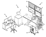
- FIG. 1 is an isometric representation of a robotic catheter system according to an embodiment.
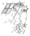
- FIG. 2 is an isometric view of an input device according to an embodiment.
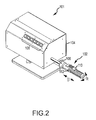
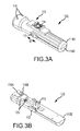
- FIGS. 3A-3D are several views of a handle for an input device according to an embodiment.
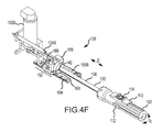
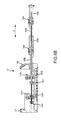
- FIGS. 4A-4F are several views of a controller with an input device according to an embodiment.
- FIG. 5 generally illustrates an input system according to an embodiment.
- FIGS. 6A and 6B are isometric and side views, respectively, of an input device according to an embodiment.
- FIGS. 7A and 7B are side and isometric views, respectively, of an embodiment of a handle for an input device.
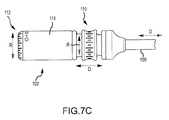
- FIGS. 7C and 7D are side and isometric views, respectively, of another embodiment of a handle for an input device.
- FIGS. 7E and 7F are side and isometric views, respectively, of yet another embodiment of a handle for an input device.
- FIGS. 7G-7I are side and isometric views of still another embodiment of a handle for an input device.
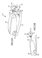
- FIGS. 8A and 8B are isometric views of an input device according to an embodiment.
- FIG. 8C is an isometric view of a handle of input device, the handle being of the type generally illustrated in FIGS. 8A and 8B .
- FIGS. 9A and 9B are views of an input device according to an embodiment, FIG. 9A being an isometric view and FIG. 9B being a side elevation view.
- FIGS. 10A , 10 B, and 10 C are isometric views of an input device according to an embodiment.
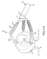
- FIG. 11A is an isometric view of an input device according to an embodiment.
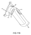
- FIG. 11B is an isometric view of a handle, the handle being of the type generally illustrated in FIG. 11A .
- system 10 may be used, for example, to manipulate the location and orientation of catheters and sheaths in a treatment area, such as within a heart chamber or another body cavity.
- system 10 may include an input control system 100 .
- Input control system 100 may include an input device, such as a joystick, and related controls (further described below), that a user such as an electrophysiologist (EP) may interact with.
- EP electrophysiologist
- Input control system 100 may be coupled to an electronic control system 200 that translates motions of the user at or with respect to the input device into a resulting movement of a catheter tip.
- a visualization system 12 may provide a user with real-time or near-real-time positioning information concerning the catheter tip.
- the system 10 may further include a closed-loop feedback system 14 , for example, an EnSite NavXTM system, a magnetic positioning system, and/or optical force transducers.
- the system 10 may additionally include a robotic catheter manipulator assembly 300 for operating a robotic catheter device cartridge 400 , and manipulator support structure 1100 .
- the system 10 provides the user with a similar type of control provided by a conventional manual system, but allows for repeatable, precise, and dynamic movements.
- system 10 may be omitted, or may be combined.
- electronic control system 200 is illustrated as a stand-alone unit, it is understood that it may be incorporated into another device, such as manipulator support structure 1100 .
- Input control system 100 may permit a user to control the movement and advancement of both a catheter and sheath.
- input devices may be employed.
- the subject input devices of this teaching include, without limitation, instrumented catheter handle controls which may comprise one or more joysticks generally resembling traditional catheter controls.
- the input device may be self-centering, so that a movement from the center position causes an incremental movement of the actual catheter tip.
- the input device may work in absolute terms.
- Haptic feedback may also be employed in connection with the input device or input control system 100 to provide a user with a physical indication associated with contact (e.g., an indication when contact has been made).
- haptic feedback may include heating or cooling a handle of the input device (e.g., to provide a user with an indication as to electrode temperature); vibrating a handle (e.g., to indicate contact with tissue); and/or providing resistance to movement of the input device.
- haptic feedback may also be employed to represent physical limitations of a device.
- haptic feedback may be provided to indicate that a catheter or sheath has reached the end of available translation, achieved a maximum deflection, and/or to indicate another physical property of an associated medical device.
- vibrating a handle, or providing resistance to movement may be implemented using one or more motors coupled or in operative communication with a handle.
- Such features may include providing feedback using a visualization system 12 , employing a magnetic positioning system, (e.g., for creating cardiac chamber geometries or models), displaying activation timing and voltage data, etc. Such features may be useful to, e.g., identify arrhythmias, guide precise movement of catheters or optical force transducers, etc. Additional features may include active tensioning of “passive” steering wires to reduce the system response time; cumulative ablation while an electrode tip is following a front-to-back ironing motion; and/or reactive/resistive impedance monitoring.
- System 10 may include visualization system 12 which may provide a user with real-time or near-real-time positioning information concerning the catheter tip.
- system 12 may include a monitor 16 for displaying cardiac chamber geometries or models, displaying activation timing and voltage data to identify arrhythmias, and for facilitating guidance of catheter movement.
- a fluoroscopy monitor 18 may be provided for displaying a real-time x-ray image for assisting a physician with catheter movement.
- Additional exemplary displays may include an Intracardiac Echo (“ICE”) and EP Pruka displays, 20 , 22 , respectively.
- ICE Intracardiac Echo
- EP Pruka displays 20 , 22 , respectively.
- System 14 (which may be of the type described in detail in U.S. Pat. No. 7,263,397, titled “Method and Apparatus for Catheter Navigation and Location and Mapping in the Heart,”) may be provided for creating realistic cardiac chamber geometries or models, displaying activation timing and voltage data to identify arrhythmias, and guiding precise catheter movement.
- System 14 may collect electrical data from catheters, may use this information to track or navigate catheter movement, and may construct three-dimensional (3-D) models of the chamber.
- robotic catheter system 10 may include one or more robotic catheter manipulator assemblies 300 , for example, for manipulating catheter and sheath cartridges.
- Manipulator assembly 300 may include interconnected/interlocking manipulation bases for catheter and sheath cartridges.
- Each interlocking base may be capable of travel in the longitudinal direction of the catheter/sheath. In an embodiment, longitudinal travel may include a translation of up to 8 linear inches or more.
- Each interlocking base may be translated by a high precision drive mechanism.
- Such a drive mechanism may include, for example and without limitation, a motor driven lead screw or ball screw.
- Robotic catheter manipulator assembly 300 may be usable with a robotic catheter rotatable device cartridge.
- Manipulator base may be replaced with a robotic catheter rotatable drive head and a robotic catheter rotatable drive mechanism.
- robotic catheter system 10 may include one or more cartridges 400 , with manipulator 300 including at least two cartridges, each of which may be configured to control the distal movement of either the catheter or the sheath.
- a catheter cartridge a catheter may be substantially connected or affixed to the cartridge, so that advancement of the cartridge correspondingly advances the catheter, and retraction of the cartridge retracts the catheter.
- Each cartridge may, for example, include slider blocks rigidly and independently coupled to one of a plurality of catheter steering wires in a manner to permit independent tensioning of each steering wire.
- the cartridge may be provided as a disposable item that is capable of being easily positioned (e.g., snapped) into place in an overall assembly.
- the cartridge may include an electrical “handshake” device or component to allow the system 10 to properly identify the cartridge (e.g., by type and/or proper placement/positioning).
- a sheath cartridge may be designed in a similar manner as the catheter cartridge, but may be configured to provide for the passage of a catheter.
- the assembly may include a plurality (e.g., as many as ten or more) of independent driving mechanisms (e.g. motor driven ball screws).
- Robotic catheter system 10 may be useful for a variety of procedures and in connection with a variety of tools and/or catheters.
- tools and/or catheters may include, without limitation, spiral catheters, ablation catheters, mapping catheters, balloon catheters, transseptal catheters, needle/dilator tools, cutting tools, cauterizing tools, and/or gripping tools.
- the system 10 may additionally include a means of identifying the nature and/or type of catheter/tool cartridge that is installed for use, and/or position or connection related information. It may also be desirable for the system 10 to automatically access/obtain additional information about the cartridge, such as, without limitation, its creation date, serial number, sterilization date, prior uses, etc.
- FIG. 2 illustrates an embodiment of an input device 101 .
- Input device 101 may be configured to allow a user to selectively control a catheter, a sheath, or both a catheter and a sheath.
- Input device 101 may include at least one handle 102 connected to a control box 104 via a spline 106 .
- control box 104 may be configured to receive inputs from a handle 102 , such as user inputs from a user manipulating handle 102 .
- Control box 104 may translate received user inputs into outputs, such as electrical signals, which may be used by a robotic catheter system 10 to control, e.g., a sheath and/or a catheter.
- Control box 104 may include one or more switches 108 .
- Switches 108 may be configured to permit selection of one or more operating parameters, preset functions, or other functions such as: returning to a preset location, such as a home, or centered position; de-tensioning a catheter or sheath; reversing most recent movement; activating/deactivation ablation energy, etc.
- Handle 102 may be configured for motion relative to control box 104 .
- the motion of handle 102 relative to control box 104 may be similar to the motion of a traditional catheter handle.
- handle 102 may be configured to rotate in the direction R, and to be laterally displaceable, or translatable, in the direction of arrow D.
- Handle 102 may include one or more switches, such as switches 110 , 112 , as will be described further below with reference to FIG. 3 .
- Control box 104 may be configured to detect motion of handle 102 , and to generate one or more electrical or control signals in response thereto. The one or more control signals may be transmitted to robotic catheter system 10 , such that manipulation of the handle 102 results in movement of a catheter and/or sheath in a manner similar to traditional catheter systems.
- FIG. 3A is an isometric view of a handle 102 according to an embodiment.
- Handle 102 includes a housing 118 comprising an upper portion 118 A and a lower portion 118 B.
- Handle 102 also includes a slider switch 110 .
- Slider switch 110 may be configured to be selectively displaceable from a center position, generally in the direction of arrow D.
- slider switch 110 may be replaced with another switch, such as a deflection dial rotatable with respect to the handle, a thumb wheel, a toggle switch, or any other appropriate switch.
- slider switch 110 may be configured to provide input representative of a desired deflection of the tip of a catheter and/or a sheath.
- Handle 102 may also include a switch 112 , which may, for example, comprise a three-position switch.
- Switch 112 may be configured to provide an input representative of a desired control scheme.
- switch 112 may have a first position wherein manipulation of handle 102 results in corresponding manipulation of a catheter.
- Switch 112 may have a second position wherein manipulation of handle 102 results in a corresponding manipulation of a sheath.
- Switch 112 may also have a third position wherein manipulation of handle 102 results in a corresponding manipulation of both a catheter and a sheath.
- Selective control, or individual control, of each of a catheter and a sheath may be beneficial in that it may allow for compound movement and bending of the distal tip of the catheter and sheath. Combined control may be beneficial when it is desired that the catheter and the sheath move, for example, in a common direction, or along a common plane.
- upper portion 118 A defines a plurality (in this case a pair) of apertures through which lights 116 may be visible.
- Lights 116 may be, for example, light emitting diodes (LEDs).
- a first light 116 A may be configured to illuminate when switch 112 is positioned such that handle 102 controls a sheath.
- a second light 116 B may be configured to illuminate when switch 112 is positioned such that handle 102 controls a catheter.
- lights 116 A, 116 B may be configured to illuminate when switch 112 is positioned such that handle 102 controls both a sheath and a catheter.
- Lights 116 A, 116 B may be the same color, or may be different colors (e.g., colors associated with the components being controlled). As such, the use of different color lights may be useful in providing a user with contrasting indications of devices selected for control.
- Handle 102 may include another switch, such as button 114 , which may be embedded in slider switch 110 .
- Button 114 may be configured to provide one or more inputs to control box 104 during operation.
- button 114 may be configured to act as a device control switch, such as a dead-man switch. For example, in such an embodiment, if button 114 is not depressed, manipulation of handle 102 will not result in manipulation of an associated catheter or sheath.
- button 114 may be configured to perform another function, such as providing an “on” signal for an associated ablation electrode.
- handle 102 may also include one or more other switches (not pictured).
- a device control switch, or dead man switch may also be implemented in another manner, such as by an optical relay or a capacitive switch which, when covered, indicates a user intends to manipulate an associated catheter or sheath.
- FIG. 3B is a partial exploded view of an embodiment of a handle 102 of the type generally illustrated in FIG. 3A .
- FIG. 3B illustrates embodiments of switches 110 , 112 , as well as lights 116 A and 116 B, mounted to lower portion 118 B.
- a bearing housing 120 which may be configured to assist in displacement of control rod 130 (as generally described in further detail with respect to FIG. 4C ).
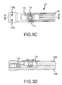
- FIG. 3C is a top view of an embodiment of handle 102 as generally shown in FIG. 3A generally illustrating switches 110 , 112 , as well as lights 116 A and 116 B.
- FIG. 3D is a sectional view along line 3 D- 3 D of FIG. 3C , further illustrating switch 110 , as well as bearing housing 120 .
- Bearing housing 120 may define an aperture through which a control rod may traverse (as generally described in further detail with respect to FIG. 4C ).
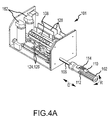
- FIG. 4A is an isometric view of input device 101 such as shown in FIG. 2 wherein the cover of control box 104 has been removed.
- FIG. 4A generally illustrates handle 102 coupled with control box 104 by spline 106 .
- Other elements illustrated in FIG. 4A will be described in further detail below, with respect to FIGS. 4B and 4C .
- FIG. 4B illustrates a top view of input device 101 of FIG. 4A , wherein switches 108 have been removed.
- input device 101 includes a handle, such as handle 102 illustrated in FIGS. 3A-3D , including switches 110 , 112 , and lights 116 A, 116 B coupled to housing 118 .
- Handle 102 is coupled to housing 104 through spline 106 .
- spline 106 may be securely coupled to handle 102 , such that manipulation of handle 102 induces a similar manipulation of spline 106 . For example, when handle 102 is rotated relative to control box 104 , spline 106 may rotate, transmitting the rotation to control box 104 .
- handle 102 when handle 102 is translated with respect to control box 104 (i.e., laterally advanced or retracted, in the direction of arrow D), spline 106 may be similarly translated, thereby transmitting the translation to control box 104 .
- spline 106 could be rigid, and handle 102 could be configured to rotate and translate with respect to spline 106 .
- handle 102 may include a rotary sensor and a translation sensor, wherein the rotary sensor could be configured to measure rotation of handle 102 with respect to spline 106 , and the translation sensor could be configured to measure translation of handle 102 with respect to spline 106 .
- Control box 104 generally includes a number of mechanisms configured to receive inputs from handle 102 and to output those inputs as electrical signals, or outputs. Accordingly, control box 104 generally includes a rotation mechanism 122 , a deflection mechanism 124 , and a translation mechanism 126 .
- Rotation mechanism 122 is configured to detect and/or measure rotational movement of handle 102 .
- Deflection mechanism 124 is configured to detect and/or measure movement of slider switch 110 .
- Translation mechanism 126 is configured to detect and/or measure translational movement of the handle 102 .
- Control box 104 may also include an interface mechanism 128 , which may be configured to transmit and/or receive one or more electrical signals, and/or to provide power to one or more of rotation mechanism 122 , deflection mechanism 124 , and translation mechanism 126 .
- slider switch 110 could be replaced with a deflection dial configured to rotate with respect to handle 102 .
- a rotary potentiometer, or other rotary sensor, could detect rotation of the dial and transmit a signal representative of the rotation.
- spline 106 may be hollow, defining an aperture therein.
- a switch control rod (or simply “control rod”) 130 may be coupled to slider switch 110 to translate motion of slider switch 110 into control box 104 .
- Control rod 130 which may be a hollow or a solid rod, may be configured to closely conform to an inner diameter of spline 106 , and bearing housing 120 , to allow control rod 130 to move within spline 106 .
- Bearing housing 120 may include one or more linear bearings disposed therein to facilitate displacement of the control rod 130 within bearing housing 120 .
- Rotational mechanism 122 may be configured to detect and/or measure rotational movement of handle 102 , for example, in the direction denoted by arrow R.
- Rotational mechanism 122 generally includes a motor 132 and a rotational potentiometer 136 coupled to spline 106 .
- Motor 132 may be coupled to rotational potentiometer 136 .
- Rotational potentiometer 136 may be connected to a hub 137 , which hub 137 is connected to the spline 106 , using a belt 134 .
- Spline 106 may be configured such that rotation of spline 106 causes a corresponding rotation of rotational potentiometer 136 , through the rotation of belt 134 .
- spline 106 , hub 137 and rotational potentiometer 136 may be configured such that spline 106 may be displaced laterally (e.g., in the direction of arrow D) with respect to rotational potentiometer 136 , independently of rotation of spline 106 and rotational potentiometer 136 . That is, spline 106 may be translated in a direction generally corresponding to arrow D without any substantial effect on rotational potentiometer 136 .
- rotational potentiometer 136 may be configured to be displaced laterally in a manner consistent with lateral displacement of spline 106 .
- Motor 132 may be configured to rotate in response to a rotation of spline 106 .
- Rotation of motor 132 may be driven in a direct-drive manner, without any intermediate gearing or reduction of power or speed. That is, rotation of motor 132 may be directly resultant from a rotation of spline 106 .
- rotation of motor 132 may be indirect, such as through belt 134 , rotational potentiometer 136 , and/or hub 137 .
- rotational potentiometer 136 When rotated, rotational potentiometer 136 may be configured to transmit a signal to, for example, a controller (not pictured) or an electronic interface, such as interface mechanism 128 .
- the controller, or interface mechanism 128 may receive the signal from rotational potentiometer 136 and may determine one or more properties of the rotation. For example, the angle of rotation may be determined based on the number of counts received by a controller, or a voltage change of a potentiometer, and the speed of rotation could be determined by computing the time derivative of the calculated position.
- motor 132 may be configured to cause rotational movement of spline 106 .
- the system may include a self-centering feature, wherein spline 106 , and handle 102 , may return to a home position, as if connected to a torsional spring.
- Motor 132 may be configured to receive a signal from a controller, such as interface mechanism 128 , which may cause motor 132 to return spline 106 to the home position.
- Deflection mechanism 124 may be configured to detect and/or measure linear displacement of a switch, such as slider switch 110 , in a direction such as corresponding to arrow D.
- slider switch 110 may be coupled to control rod 130 , which may translate lateral motion of slider switch 110 into control box 104 through an aperture defined within spline 106 .
- control rod 130 may be coupled at a distal end to a linear potentiometer 138 A.
- Linear potentiometer 138 A may be configured to detect and/or measure linear displacement of control rod 130 , and thus may detect and/or measure linear displacement of slider switch 110 .
- Linear potentiometer 138 A may be electrically connected to a controller (not shown) and/or may be connected to an interface, such as interface mechanism 128 .
- Linear potentiometer 138 A may be configured to provide an output signal in response to linear motion of control rod 130 , which may be used by a controller, such as interface mechanism 128 .
- the received signal may be used to determine one or more of the speed, the direction, the force, and the magnitude of the displacement.
- Translation mechanism 126 may be configured to detect and/or measure linear displacement of handle 102 , in a direction such as corresponding to arrow D.
- handle 102 may be coupled to a proximal end of spline 106 .
- Spline 106 may be coupled at a distal end to a linear potentiometer 138 B.
- Linear potentiometer 138 B may be configured to detect and/or measure linear displacement of spline 106 , and thus may detect and/or measure linear displacement of handle 102 .
- Linear potentiometer 138 B may be electrically connected to a controller (not shown) and/or may be connected to an interface, such as interface mechanism 128 .
- Linear potentiometer 138 B may be configured to provide an output signal in response to linear motion of handle 102 , which may be received by the controller, such as interface mechanism 128 .
- the received signal may be used to determine one or more of the speed, the direction, the force, and the magnitude of the linear displacement of handle 102 .
- Deflection mechanism 124 and translation mechanism 126 may be mounted to respective bases, 140 , 142 .
- deflection base 140 may be configured to interact with translation base 142 , for example, as further described below.
- an embodiment of a deflection base 140 may include a deflection rail 144 along which a deflection body 146 may translate laterally.
- Deflection body 146 may be coupled to control rod 130 , and to a plunger of linear potentiometer 138 A.
- Deflection body 146 may also be coupled to a belt clamp 148 A, which is configured to be securely coupled to a belt 150 A.
- deflection body 146 When control rod 130 is displaced, deflection body 146 may also be displaced, which may cause plunger of linear potentiometer 138 A to be pushed into the outer cylinder of linear potentiometer 138 A. Distal displacement of control rod 130 , and the corresponding displacement of displacement body 146 of deflection mechanism 124 , may cause a rotation of belt 150 A, as further described below.
- translation base 142 may include a translation body 152 configured to translate along a translation rail 154 in response to translation of handle 102 .
- Translation rail 154 may be secured, for example, to a lower inner face of control box 104 .
- Translation body 152 may include a proximal riser 156 configured to support spline 106 .
- Riser 156 may support spline 106 directly or, for example, using a rotatable hub 158 .
- Rotatable hub 158 may allow rotation of handle 102 , and associated rotation of spline 106 , to occur without imparting a significant torque on riser 156 .
- Riser 156 may also be coupled to the plunger of linear potentiometer 138 B.
- spline 106 When handle 102 is translated, such as in a direction corresponding to arrow D, spline 106 may be similarly translated, which may impart a lateral force on hub 158 .
- the force on hub 158 may cause riser 156 to move laterally, forcing the plunger of linear potentiometer 138 B into the cylinder of linear potentiometer 138 B.
- riser 156 As riser 156 is translated, translation body 152 may move laterally along the rail 154 .
- Translation body 152 may also include a belt clamp 148 B (not pictured) coupled to a belt 150 B. Movement of translation body 152 may cause belt 150 B to move.
- deflection mechanism 124 may be mounted on translation mechanism 126 .
- translation body 152 may include a groove 160 defined therein.
- Deflection rail 144 may be configured to be coupled in groove 160 .
- linear potentiometer 138 A may be coupled, at a distal end, to translation body 152 .
- Deflection mechanism 124 may be configured such that linear displacement of translation mechanism 126 , such as displacement along the direction of arrow D, will not affect deflection mechanism 124 . That is, the entire deflection mechanism 124 may move laterally, resulting in no net change in the deflection mechanism 124 . Accordingly, deflection may be maintained without impairing the ability to translate handle 102 .
- Each of the belts 150 A, 150 B may be configured to couple deflection mechanism 124 and translation mechanism 126 to respective motors 162 A, 162 B.
- motors 162 A, 162 B may be coupled with an associated controller, and/or may be connected to interface mechanism 128 .
- Motors 162 A, 162 B may transmit signals representative of motion induced on the motor, such as by induction mechanism 124 or translation mechanism 126 .
- motors 162 A and 162 B may be configured to induce motion of respective mechanisms 124 , 126 .
- the system may be equipped with a self centering feature.
- Motor 162 A may be configured to receive signals from an interface, such as interface mechanism 128 , and to induce motion in deflection mechanism 124 to return deflection mechanism 124 to an initial or a centered state.
- Centered state may refer to the geometric center of the available motion of the deflection slider switch 110 .
- Centered state may, additionally or alternatively, refer to a preset position or state programmable prior to, or during, a procedure.
- motor 162 B may be configured to receive position signals, and to return translation mechanism 126 , and the associated spline 106 , to a centered state.
- FIG. 5 generally illustrates an exemplary input system 100 .
- Input system 100 includes a computing system 102 configured to receive control signals from input device 101 , and to display information related to the input control system 100 on one or more displays 103 .
- Displays 103 may be configured to provide visual indications related to patient health, equipment status, catheter position, ablation related information, or other information related to catheter procedures.
- Computing system 102 may be configured to receive signals from input device 101 , and to process those signals. For example, computing system 102 may receive signals indicative of a desired motion of a catheter within a patient, may format those signals, and transmit the signals to a manipulator system, such as manipulator system 300 . The manipulator system may receive the signals and cause a corresponding motion of the catheter.
- Position, location, and movement of an associated catheter or sheath may be displayed to a user, such as an electrophysiologist, on display 103 .
- the relationship between the movement of the input device 101 and an associated catheter and/or sheath may be affected in part by one or more control parameters or settings associated with computing system 102 .
- Control parameters or settings may be provided by a user, such as an EP, through manipulation of software associated with computing device 102 , through one or more inputs (e.g. inputs 108 ), or through other conventional control means.
- Control parameters or settings may include, without limitation, scaling values which may affect the magnitude or velocity at which the associated catheter or sheath is displaced in response to a given user input. For example, a scaling value of 2 may result in a catheter or sheath moving twice the distance that the catheter or sheath would move with respect to a scaling value of 1.
- FIG. 6A is an isometric view of an input device 101 ′ according to a another embodiment.
- input device 101 ′ includes a first handle 102 A and a second handle 102 B.
- a first spline 106 A is illustrated extending through a proximal end of handle 102 B, and is coupled with handle 102 A.
- a second spline 106 B is coupled to a distal end of handle 102 B, and with control box 104 ′.
- Each of handles 110 A and 110 B include a slider switch 112 A, 112 B.
- handle 102 A may be configured to control a catheter, and handle 102 B may be configured to control a sheath.
- handles 102 A, 102 B may be configured to move independently.
- Slider switch 110 A may be configured to control deflection of an associated catheter, and slider switch 110 B may be configured to control deflection of an associated sheath.
- FIG. 6B is an isometric view of input device 101 ′ as generally shown in FIG. 6A , further illustrating the mechanisms housed within control box 104 ′.
- Input device 101 ′ generally includes a first rotation mechanism 122 A, a first deflection mechanism 124 a , and a first translation mechanism 126 A, as well as a second rotation mechanism 122 B, a second deflection mechanism 124 B, and a second translation mechanism 126 B. Operation of the mechanisms may be similar to the operation described in further detail above with respect to the foregoing drawings.
- Mechanisms 122 A, 124 a , and 126 A are coupled with first handle 102 A, and are respectively configured to detect rotation, deflection, and translation of handle 102 A, as well as to transmit signals representative thereof to an associated controller.
- handles such as handle 102 , 102 A, 102 B, may be configured to be removable and replaceable.
- a first user may prefer a handle 102 having a slider switch 110 to control deflection.
- a second user may prefer a handle 102 having a dial switch (not pictured) to control deflection.
- a handle 102 may be configured to be easily removed and replaced with a handle including varying methods of providing input.
- FIGS. 7A-7B illustrate an additional embodiment of a handle 102 for use with an input device 101 .
- Handle 102 includes a trigger switch 110 which may, for example, be configured to control the distal end of a medical device, such as a catheter and/or a sheath.
- a switch 112 may be configured to allow a user to select one or both of a catheter and sheath for control.
- a rotation input 113 may be configured to allow a user to control rotation of an associated medical device, such as a catheter and/or sheath.
- housing 118 which may include an upper housing 118 A and lower housing 118 B, and may be soft, contoured, or textured to allow for a more comfortable grip.
- Handle 102 may be configured to allow a user to control translation of a catheter and/or sheath, such as by pushing or pulling handle 102 along spline 106 , generally in the direction of arrow D. Handle 102 may further include lights (not shown) to indicate the position of switch 112 , which may provide an indication of one or more medical instruments selected for control.
- FIGS. 7C and 7D illustrate another embodiment of a handle 102 for use with an input device 101 (see, e.g., FIG. 2 ).
- Handle 102 includes a rotary switch 110 which may be displaceable in the direction of arrow D.
- Switch 110 may be configured such that displacement of switch 110 in the direction of the arrow D may control deflection of the distal end of an associated medical device, such as a catheter and/or a sheath.
- Switch 110 may be further configured such that rotation of switch 110 may control rotation of a catheter and/or sheath.
- Handle 102 may include a second switch 112 , which may be a second rotary switch. Switch 112 may be configured to allow a user to select one or both of a catheter and sheath for control.
- Housing 118 which may include an upper housing 118 A and a lower housing 118 B, may be soft, contoured, and/or textured to allow for a more comfortable grip. Translation of a catheter and/or sheath may be controlled by pushing or pulling handle 102 along spline 106 , generally in the direction of arrow D. Rings of lights 116 may be provided, and may be configured to indicate the position of switch 112 , which may provide an indication of one or more associated medical instruments selected for control.
- FIGS. 7E-7F generally illustrate another embodiment of a handle 102 for use with an input device 101 .
- Handle 102 may be configured such that moving handle 102 up or down, generally in the direction of arrow X, may control deflection of the distal end of an associated medical device, such as a catheter and/or sheath.
- Handle 102 may include a switch 112 which may allow selection of one or more associated medical devices, such as selection of one or both of a catheter and sheath, for control.
- Handle 102 may include a rotation input 113 which may be configured to allow a user to control rotation of a catheter and/or sheath.
- Housing 118 may be soft, contoured, textured, etc., to provide a user with a more comfortable grip.
- Translation of a catheter and/or sheath may be controlled by pushing or pulling handle 102 along spline 106 , generally in the direction of arrow D.
- Lights 116 A, 116 B may be used to indicate the position of switch 112 , which may provide an indication of one or more medical instruments selected for control.
- FIGS. 7G-7I illustrate yet another embodiment of a handle 102 for use with an input device 101 .
- Handle 102 may be configured such that moving handle 102 up or down, generally in the direction of arrow X ( FIG. 7G ), may control translation of the distal end of an associated catheter and/or sheath.
- Handle 102 may be further configured such that moving handle 102 to one side or the other, generally in the direction of arrow Y ( FIG. 7H ), may control deflection of the distal end of an associated catheter and/or sheath.
- Handle 102 may be further configured such that rotating handle 102 , for example, in the direction of arrow R ( FIG. 7I ), may control rotation of an associated catheter and/or sheath.
- Handle 102 may include a selector switch 112 which may allow selection of one or both of a catheter and sheath for control.
- FIG. 8A generally illustrates an input device 101 including a handle 102 which may be coupled to a control box 104 via spline 106 .
- Handle 102 may include a switch 110 which may be configured to control deflection of an associated medical device, such as an associated catheter and/or sheath.
- Handle 102 may also include a toggle switch 112 which may be configured to allow, e.g., selection of one or both of a catheter and sheath for control.
- Handle 102 may further include a rotary switch 113 which may be configured to allow a user to control rotation of an associated catheter and/or sheath, such as by rotating switch 113 in the direction of arrow R.
- Handle 102 may further include a translation switch 115 which may be configured to control translation of an associated catheter and/or sheath.
- Housing 118 of handle 102 may include a contoured or textured grip, such as a silicone grip, for improved comfort.
- Control box 104 may include a switch 114 , which may be configured to serve as a dead man switch.
- Control box 104 may also include one or more displays and indicators. For example, an acrylic display may be used to display functions.
- One or more lights 116 may be provided and may be used to indicate the position of switch 112 , which may provide an indication of one or more medical instruments selected for control.
- FIG. 8B generally illustrates another embodiment of an input device 101 , similar to the input device of FIG. 8A .
- FIG. 8C is an enlarged view of a handle 102 of the type shown in FIG. 8B .
- Handle 102 may be coupled to a control box 104 via spline 106 .
- Spline 106 may be rigid, or may be flexible.
- Spline 106 may be configured to transmit one or more electrical signals between handle 102 and control box 104 .
- Handle 102 may include a trigger switch 110 which may be configured to control deflection of an associated medical device, such as an associated catheter and/or sheath. The amount by which trigger switch 110 may travel may be adjustable.
- Handle 102 may also include a toggle switch 112 which may me configured to allow selection of one or both of a catheter and sheath for control.
- a rotary switch 113 may be configured to control rotation of an associated catheter and/or sheath, such as by rotating switch 113 in the direction of arrow R.
- Handle 102 may further include a translation switch 115 which may be configured to control translation of, e.g., an associated catheter and/or sheath.
- Housing 118 of handle 102 may include a textured grip, such as a silicone grip, for improved comfort.
- Control box 104 may also include one or more displays and indicators. For example, a display may be used to display functions.
- One or more lights 116 may be provided and may be configured to indicate the position of switch 112 , and thereby provide an indication of one or more associated medical instruments selected for control.
- Control box may further include a holding rack 119 , which may be retractable, may be configured, e.g., to hold handle 102 when handle 102 is not in use.
- FIGS. 9A and 9B generally illustrate another embodiment of an input device 101 including a handle 102 coupled to a control box 104 via a spline 106 .
- Handle 102 may include a generally spherical switch 110 .
- Switch 110 may be configured such that rotation of switch 110 may allow a user to control rotation of an associated medical device, such as a catheter and/or sheath.
- Handle 102 may also include, or be coupled with, a second rotary switch 113 which may be configured such that rotation of switch 113 may control deflection of the distal end of an associated medical device, such as, a catheter and/or sheath.
- Handle 102 may include a toggle switch 112 which may be configured to allow a user to select, e.g., one or both of an associated catheter and sheath for control. Handle 102 may further include a switch 114 which may be configured to serve as a dead man switch 114 .
- Control box 104 may be coupled to a base 121 via one or more rotary couplers 123 .
- Rotary couplers 123 may be selectively adjustable to allow changing of the angle of control box 104 .
- Base 121 may include an emergency stop button 125 , which may be configured to, e.g., retract an associated medical device, such as a catheter and/or sheath, or to remove ablation energy from an ablation catheter.
- Base 121 may further include one or more switches 127 , which may be selectively assignable by a user.
- FIGS. 10A , 10 B and 10 C generally illustrate an embodiment of a handle 102 for an input device.
- Handle 102 may be contoured, for example, to conform to the hand of a user.
- Handle 102 may be designed to conform to either a right hand or a left hand.
- Input may be provided to an input control system 100 , for example, using a trackball 129 and one or more assignable buttons 131 .
- Buttons 131 may be configured to allow a user to, e.g., select one or more of a catheter and sheath for control. Additionally, buttons 131 may be configured to allow a user to select a function which may be controlled using trackball 129 .
- a first button 131 A may be configured such that selection of button 131 A causes trackball 129 to control deflection of the distal end of an associated catheter or sheath.
- a second button 131 B may be configured such that selection of button 131 B allows trackball 129 to control translation of an associated catheter or sheath.
- handle 102 may be configured such that moving trackball 129 in a first direction, such as left or right, controls an associated catheter or sheath in a first manner, such as by controlling deflection of the catheter or sheath, and movement of trackball 129 in a second direction, such as forward and backward, controls an associated catheter or sheath in a second manner, such as by controlling translation.
- Handle 102 may include one or more mounting holes to allow handle 102 to be mounted, for example, on a machine, a table, or to another medical device.
- FIG. 11A generally illustrates a side isometric of an input device 101 according to an embodiment.
- FIG. 11B generally illustrates an isometric view of a handle 102 which may be configured for use with input device 101 .
- Input device 101 may be a spatial input device, which may be configured to allow a user to move handle 102 in three dimensions.
- Handle 102 may be coupled to a control box 104 via a plurality of control arms 133 .
- Control arms 133 may include several sections 135 A- 135 d which may pivot and collectively allow movement of handle 102 in a spherical plane. While FIG. 11A illustrates two control arms 133 , it is to be understood that input device 101 may include any number of control arms 133 .
- input device 101 includes three control arms 133 .
- One or more of sections 135 may be coupled to one or more motors, sensors, or controllers, such as motor 141 .
- Handle 102 may be coupled to control arms 133 at a base 139 , which may include one or more mounting points.
- Handle 102 may include a first rotary switch 110 which may be configured to allow a user to control an associated medical device, such as an associated catheter and/or sheath. For example, movement of handle 102 in the x-y plane may result in motion of the distal end of a catheter and/or sheath in the x-y plane.
- Handle 102 may include a housing 118 coupled to the one or more control arms 133 through a base 117 .
- housing 118 may be rigidly coupled to base 117 .
- housing 118 may be rotatably coupled to base 117 through a rotary switch 113 .
- Rotary switch 113 may be configured to allow a user to control one or more properties of an associated medical device.
- rotary switch 113 may be configured to allow a user to rotate the distal end of an associated catheter and/or sheath.
- Handle 102 may further be configured such that the angle at which housing 118 couples to base 117 may be adjustable.
- Handle 102 may further include a switch 114 which may be configured to serve as a dead man switch 114 .
- Input device 101 may be configured such that control arms 133 , and associated elements, may be configured to provide force feedback to a user.
- motors, sensors, and/or controllers may be coupled to one or more of sections 135 of arms 133 to induce, assist or resist motion in a particular direction. Multiple motors, sensors, controllers, etc., may work in concert to induce, assist, or resist motion in a spherical manner.
- input device 101 may be configured such that one or more of control arms 133 , and/or one or more of sections 135 , may be selectively lockable.
- motor 141 may selectively power, or lock one or more of motors 141 to restrict handle motion 102 .
- input device 101 may restrict handle 102 motion to a particular plane, such as an x-y plane, or may, for example, prevent motion within the x-y plane while allowing handle 102 to translate and rotate on an axis, such as the Z-axis.
- input device 101 may be configured to lock rotation along an axis, such as the Z-axis, while allowing handle 102 otherwise unrestricted movement.
Abstract
An input device for a robotic medical system includes a handle configured to be rotatable about a center axis, and to be longitudinally displaceable along the center axis. The input device also includes a deflection control element disposed on the handle and configured to selectively control deflection of the distal end of a flexible medical instrument electrically coupled to the input device. Longitudinal displacement of the handle may cause or result in a corresponding longitudinal motion or deflection of the flexible medical instrument. Rotation of the handle may cause or result in a corresponding rotation of the deflection plane. Longitudinal displacement and rotation of the handle may be detected or sensed electronically.
Description
This application claims the benefit of priority to U.S. provisional application Nos. 61/040,141, filed Mar. 27, 2008; 61/040,142, filed Mar. 27, 2008; 61/040,143, filed Mar. 27 2008; 61/099,904, filed Sep. 24, 2008; and 61/141,971, filed Dec. 31, 2008, the entire disclosures of which are hereby incorporated by reference as though fully set forth herein.
a. Field of the Invention
The present invention relates to robotic catheter systems, and more particularly, to improved input devices for controlling movement of catheters and sheaths within a treatment area, such as a cardiac chamber. Input devices according to the present teachings may also be used with other computer-based medical systems, such as simulation systems for training.
b. Background Art
Electrophysiology catheters are used for an ever-increasing number of procedures. For example, catheters have been used for diagnostic, therapeutic, mapping and ablative procedures, to name just a few examples. Typically, a catheter is manipulated through the patient's vasculature to an intended site, for example, a site within the patient's heart, and carries one or more electrodes, which may be used for mapping, ablation, diagnosis, or other treatments.
Traditional techniques of manipulating catheters to, and within, a treatment area typically include a physician manipulating a handle connected to a catheter. The handle generally includes a mechanism directly connected to guide wires for controlling the deflection of a catheter. A second handle is generally provided for controlling deflection of a sheath. Rotating and advancing a catheter or sheath generally requires an electrophysiologist (EP) to physically rotate and advance the associated handle.
Recently, catheter systems have been developed that work in concert with visualization/mapping systems, such as the NavX™ or EnSite™ systems commercialized by St. Jude Medical, Inc. However, conventional systems still generally involve an EP manually controlling a catheter and sheath system, and associated visualization systems typically reactively monitor catheter movement.
Systems are provided for receiving user inputs and providing signals representative of the user inputs to a catheter system, which may be a robotic catheter system. An embodiment of a robotic catheter system (also referred to as “the system”) may be used, for example, to manipulate the location and orientation of sheaths and catheters in a heart chamber or in another body portion. The system may incorporate a human input device, e.g., a joystick, configured for interaction with a user; an electronic control system that translates motion of the user at the input device into a resulting movement of a catheter tip; and a visualization device that provides a user with real-time or near-real-time positioning information concerning the catheter tip. The system may provide the user with a similar type of control provided by a conventional manual system, and allow for repeatable, precise, and dynamic movements. The input system may thus provide a user, such as an electrophysiologist, with an input device that mimics a device the user already understands and is familiar with.
In an embodiment, the input device includes a first handle and a second handle. The first handle and the second handle may be aligned coaxially along a shaft. The handles may include selector switches, dials or buttons such as, for example, slider switches or thumb wheels, which may be configured to control movement of the catheter and the sheath. Handles may be longitudinally displaceable along a shaft, and may be configured such that longitudinal displacement of a shaft results in a longitudinal displacement of the associated catheter/sheath. In an embodiment, the input device may include a single handle configured to control the sheath and catheter, either together or independently. In embodiments, the input device may include a selector mechanism, such as a three position switch, through which a user may selectively control the catheter, the sheath, or both the catheter and sheath.
In an embodiment, an input device may include one or more indicators configured to provide an indication to a user concerning whether a catheter, a sheath, or both a catheter and a sheath, are selected for control. For example, input devices may include an LED indicator (e.g., a white LED) to indicate a catheter is selected for control, and another LED (e.g., a blue LED) to indicate a sheath is selected for control.
In an embodiment, an input device may include a device control switch that must be activated before the user input will transmit signals indicative of user inputs. For example, a system in communication with an input device may be configured to accept inputs from user input device only when a device control switch is activated.
A system according to the present teachings may be configured to receive the inputs from the user input control, and to transmit the user inputs to a robotic catheter system configured to cause corresponding motion of a catheter system.
Referring now to the drawings wherein like reference numerals are used to identify like components in the various views, an embodiment of a robotic catheter system 10 (described in detail in co-pending application titled “Robotic Catheter System” filed Sep. 24, 2008, hereby incorporated herein by reference in its entirety), also referred to as “the system,” is illustrated. The system 10 may be used, for example, to manipulate the location and orientation of catheters and sheaths in a treatment area, such as within a heart chamber or another body cavity. As generally illustrated in FIG. 1 , system 10 may include an input control system 100. Input control system 100 may include an input device, such as a joystick, and related controls (further described below), that a user such as an electrophysiologist (EP) may interact with. Input control system 100 may be coupled to an electronic control system 200 that translates motions of the user at or with respect to the input device into a resulting movement of a catheter tip. A visualization system 12 may provide a user with real-time or near-real-time positioning information concerning the catheter tip. The system 10 may further include a closed-loop feedback system 14, for example, an EnSite NavX™ system, a magnetic positioning system, and/or optical force transducers. The system 10 may additionally include a robotic catheter manipulator assembly 300 for operating a robotic catheter device cartridge 400, and manipulator support structure 1100. The system 10 provides the user with a similar type of control provided by a conventional manual system, but allows for repeatable, precise, and dynamic movements. In an embodiment, certain elements described above with respect to system 10 may be omitted, or may be combined. For example, while electronic control system 200 is illustrated as a stand-alone unit, it is understood that it may be incorporated into another device, such as manipulator support structure 1100.
Many additional features may be included with the system 10, which may be used to help improve the accuracy and/or effectiveness of the system. Such features may include providing feedback using a visualization system 12, employing a magnetic positioning system, (e.g., for creating cardiac chamber geometries or models), displaying activation timing and voltage data, etc. Such features may be useful to, e.g., identify arrhythmias, guide precise movement of catheters or optical force transducers, etc. Additional features may include active tensioning of “passive” steering wires to reduce the system response time; cumulative ablation while an electrode tip is following a front-to-back ironing motion; and/or reactive/resistive impedance monitoring.
Referring further to FIG. 1 , aspects of system 14 will be additionally described.
System 14 (which may be of the type described in detail in U.S. Pat. No. 7,263,397, titled “Method and Apparatus for Catheter Navigation and Location and Mapping in the Heart,”) may be provided for creating realistic cardiac chamber geometries or models, displaying activation timing and voltage data to identify arrhythmias, and guiding precise catheter movement. System 14 may collect electrical data from catheters, may use this information to track or navigate catheter movement, and may construct three-dimensional (3-D) models of the chamber.
As generally shown in FIG. 1 , robotic catheter system 10 may include one or more robotic catheter manipulator assemblies 300, for example, for manipulating catheter and sheath cartridges. Manipulator assembly 300 may include interconnected/interlocking manipulation bases for catheter and sheath cartridges. Each interlocking base may be capable of travel in the longitudinal direction of the catheter/sheath. In an embodiment, longitudinal travel may include a translation of up to 8 linear inches or more. Each interlocking base may be translated by a high precision drive mechanism. Such a drive mechanism may include, for example and without limitation, a motor driven lead screw or ball screw.
Robotic catheter manipulator assembly 300 may be usable with a robotic catheter rotatable device cartridge. Manipulator base may be replaced with a robotic catheter rotatable drive head and a robotic catheter rotatable drive mechanism.
As briefly discussed above, robotic catheter system 10 may include one or more cartridges 400, with manipulator 300 including at least two cartridges, each of which may be configured to control the distal movement of either the catheter or the sheath. With respect to a catheter cartridge, a catheter may be substantially connected or affixed to the cartridge, so that advancement of the cartridge correspondingly advances the catheter, and retraction of the cartridge retracts the catheter. Each cartridge may, for example, include slider blocks rigidly and independently coupled to one of a plurality of catheter steering wires in a manner to permit independent tensioning of each steering wire. The cartridge may be provided as a disposable item that is capable of being easily positioned (e.g., snapped) into place in an overall assembly. In an embodiment, the cartridge may include an electrical “handshake” device or component to allow the system 10 to properly identify the cartridge (e.g., by type and/or proper placement/positioning). A sheath cartridge may be designed in a similar manner as the catheter cartridge, but may be configured to provide for the passage of a catheter. The assembly may include a plurality (e.g., as many as ten or more) of independent driving mechanisms (e.g. motor driven ball screws).
Handle 102 may also include a switch 112, which may, for example, comprise a three-position switch. Switch 112 may be configured to provide an input representative of a desired control scheme. For example, switch 112 may have a first position wherein manipulation of handle 102 results in corresponding manipulation of a catheter. Switch 112 may have a second position wherein manipulation of handle 102 results in a corresponding manipulation of a sheath. Switch 112 may also have a third position wherein manipulation of handle 102 results in a corresponding manipulation of both a catheter and a sheath. Selective control, or individual control, of each of a catheter and a sheath may be beneficial in that it may allow for compound movement and bending of the distal tip of the catheter and sheath. Combined control may be beneficial when it is desired that the catheter and the sheath move, for example, in a common direction, or along a common plane.
In the illustrated embodiment, upper portion 118A defines a plurality (in this case a pair) of apertures through which lights 116 may be visible. Lights 116 may be, for example, light emitting diodes (LEDs). A first light 116A may be configured to illuminate when switch 112 is positioned such that handle 102 controls a sheath. A second light 116B may be configured to illuminate when switch 112 is positioned such that handle 102 controls a catheter. In an embodiment, lights 116A, 116B may be configured to illuminate when switch 112 is positioned such that handle 102 controls both a sheath and a catheter. Lights 116A, 116B may be the same color, or may be different colors (e.g., colors associated with the components being controlled). As such, the use of different color lights may be useful in providing a user with contrasting indications of devices selected for control.
Handle 102 may include another switch, such as button 114, which may be embedded in slider switch 110. Button 114 may be configured to provide one or more inputs to control box 104 during operation. In an embodiment, button 114 may be configured to act as a device control switch, such as a dead-man switch. For example, in such an embodiment, if button 114 is not depressed, manipulation of handle 102 will not result in manipulation of an associated catheter or sheath. In another embodiment, button 114 may be configured to perform another function, such as providing an “on” signal for an associated ablation electrode. It is understood that handle 102 may also include one or more other switches (not pictured). A device control switch, or dead man switch, may also be implemented in another manner, such as by an optical relay or a capacitive switch which, when covered, indicates a user intends to manipulate an associated catheter or sheath.
As illustrated in FIG. 4C , spline 106 may be hollow, defining an aperture therein. A switch control rod (or simply “control rod”) 130 may be coupled to slider switch 110 to translate motion of slider switch 110 into control box 104. Control rod 130, which may be a hollow or a solid rod, may be configured to closely conform to an inner diameter of spline 106, and bearing housing 120, to allow control rod 130 to move within spline 106. Bearing housing 120 may include one or more linear bearings disposed therein to facilitate displacement of the control rod 130 within bearing housing 120.
In an embodiment, motor 132 may be configured to cause rotational movement of spline 106. For example, the system may include a self-centering feature, wherein spline 106, and handle 102, may return to a home position, as if connected to a torsional spring. Motor 132 may be configured to receive a signal from a controller, such as interface mechanism 128, which may cause motor 132 to return spline 106 to the home position.
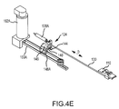
In an embodiment, as illustrated in FIG. 4F , translation base 142 may include a translation body 152 configured to translate along a translation rail 154 in response to translation of handle 102. Translation rail 154 may be secured, for example, to a lower inner face of control box 104. Translation body 152 may include a proximal riser 156 configured to support spline 106. Riser 156 may support spline 106 directly or, for example, using a rotatable hub 158. Rotatable hub 158 may allow rotation of handle 102, and associated rotation of spline 106, to occur without imparting a significant torque on riser 156. Riser 156 may also be coupled to the plunger of linear potentiometer 138B. When handle 102 is translated, such as in a direction corresponding to arrow D, spline 106 may be similarly translated, which may impart a lateral force on hub 158. The force on hub 158 may cause riser 156 to move laterally, forcing the plunger of linear potentiometer 138B into the cylinder of linear potentiometer 138B. As riser 156 is translated, translation body 152 may move laterally along the rail 154. Translation body 152 may also include a belt clamp 148B (not pictured) coupled to a belt 150B. Movement of translation body 152 may cause belt 150B to move.
As illustrated, for example, in FIGS. 4A-4F , deflection mechanism 124 may be mounted on translation mechanism 126. In an embodiment, translation body 152 may include a groove 160 defined therein. Deflection rail 144 may be configured to be coupled in groove 160. In such an embodiment, linear potentiometer 138A may be coupled, at a distal end, to translation body 152. Deflection mechanism 124 may be configured such that linear displacement of translation mechanism 126, such as displacement along the direction of arrow D, will not affect deflection mechanism 124. That is, the entire deflection mechanism 124 may move laterally, resulting in no net change in the deflection mechanism 124. Accordingly, deflection may be maintained without impairing the ability to translate handle 102.
Each of the belts 150A, 150B may be configured to couple deflection mechanism 124 and translation mechanism 126 to respective motors 162A, 162B. In an embodiment, motors 162A, 162B may be coupled with an associated controller, and/or may be connected to interface mechanism 128. Motors 162A, 162B may transmit signals representative of motion induced on the motor, such as by induction mechanism 124 or translation mechanism 126. Additionally, or alternatively, motors 162A and 162B may be configured to induce motion of respective mechanisms 124, 126. For example, the system may be equipped with a self centering feature. Motor 162A may be configured to receive signals from an interface, such as interface mechanism 128, and to induce motion in deflection mechanism 124 to return deflection mechanism 124 to an initial or a centered state. “Centered state” may refer to the geometric center of the available motion of the deflection slider switch 110. “Centered state” may, additionally or alternatively, refer to a preset position or state programmable prior to, or during, a procedure. Similarly, motor 162B may be configured to receive position signals, and to return translation mechanism 126, and the associated spline 106, to a centered state.
In an embodiment, handle 102A may be configured to control a catheter, and handle 102B may be configured to control a sheath. In such an embodiment, handles 102A, 102B may be configured to move independently. Slider switch 110A may be configured to control deflection of an associated catheter, and slider switch 110B may be configured to control deflection of an associated sheath.
In an embodiment, handles, such as handle 102, 102A, 102B, may be configured to be removable and replaceable. For example, a first user may prefer a handle 102 having a slider switch 110 to control deflection. A second user may prefer a handle 102 having a dial switch (not pictured) to control deflection. A handle 102 may be configured to be easily removed and replaced with a handle including varying methods of providing input.
Although embodiments of this invention have been described above with a certain degree of particularity, those skilled in the art could make numerous alterations to the disclosed embodiments without departing from the spirit or scope of this invention. For example, while embodiments have been described using potentiometers, it is to be understood that additional embodiment could include other types of sensors and encoders including, without limitation, absolute position encoders, relative position encoders, optical encoders, linear encoders, linear actuators, and linear variable differential transformers. All directional references (e.g., upper, lower, upward, downward, left, right, leftward, rightward, top, bottom, above, below, vertical, horizontal, clockwise, and counterclockwise) are only used for identification purposes to aid the reader's understanding of the present invention, and do not create limitations, particularly as to the position, orientation, or use of the invention. Joinder references (e.g., attached, coupled, connected, and the like) are to be construed broadly and may include intermediate members between a connection of elements and relative movement between elements. As such, joinder references do not necessarily infer that two elements are directly connected and in fixed relation to each other. It is intended that all matter contained in the above description or shown in the accompanying drawings shall be interpreted as illustrative only and not limiting. Changes in detail or structure may be made without departing from the spirit of the invention as defined in the appended claims.
Claims (24)
1. An input device for a robotic medical system including a medical instrument with a distal end, the input device comprising:
an input device handle configured to remotely control said medical instrument, to be rotatable about an axis, and to be longitudinally displaceable along the axis;
a first sensor configured to detect axial rotation of the input device handle;
a second sensor configured to detect longitudinal displacement of the input device handle along the axis; and
a deflection control element disposed on or about the input device handle and configured to selectively control deflection of said distal end of said medical instrument within a deflection plane via a control rod operatively connected to the deflection control element;
a hollow spline operatively coupled with the input device handle, the hollow spline having an aperture configured to permit motion of the control rod within the aperture;
wherein longitudinal displacement of the input device handle results in a corresponding longitudinal motion of said medical instrument, wherein the corresponding longitudinal motion of said medical instrument is proportional to the longitudinal displacement of the input device handle; rotation of the input device handle results in a corresponding rotation of the deflection plane, wherein the corresponding rotation of the deflection plane is proportional to the rotation of the input device handle; and the longitudinal displacement and rotation of the input device handle are detected electronically and outputted as electrical signals representative of the longitudinal displacement of the input device handle and the rotation of the input device handle.
2. The input device of claim 1 , wherein said medical instrument includes at least one of a catheter and a sheath, and the input device includes a selection switch configured to permit selective control of the catheter, sheath, or catheter and sheath.
3. The input device of claim 2 , further comprising one or more indicators indicating whether the input device handle is configured to remotely control the catheter, the sheath, or both the catheter and sheath.
4. The input device of claim 1 , wherein the input device is configured to return to an initial or centered position after displacement.
5. The input device of claim 1 , further comprising at least one sensor operatively connected or coupled to the input device handle, the at least one sensor configured to detect at least one of displacement of the input device handle, rotation of the input device handle, and displacement of a switch.
6. The input device of claim 5 , further comprising a control system configured to receive from at least one of the first sensor and the second sensor the electrical signals representative of the longitudinal displacement of the input device handle and the rotation of the input device handle, format the electrical signals, and output the formatted electrical signals to a manipulator assembly configured to cause or result in a corresponding displacement of said medical instrument.
7. The input device of claim 6 , wherein the velocity of the displacement of said medical instrument is proportional to the magnitude of the displacement of the at least one sensor.
8. The input device of claim 5 , wherein the at least one sensor is at least one of a potentiometer, a motor, and an encoder.
9. The input device of claim 5 , further comprising at least one servo motor configured to return the input device handle to an initial or centered position after displacement.
10. The input device of claim 9 , wherein the at least one servo motor is coupled to the input device handle in a direct-drive configuration.
11. The input device of claim 1 , further comprising a dead man switch that is configured to prevent unintentional control of said medical instrument.
12. The input device of claim 11 , wherein the dead man switch is an optical switch or a capacitive switch configured to detect the presence or absence of a portion of a hand in contact with at least a portion of the input device handle.
13. The input device of claim 1 , wherein the input device handle comprises a first input device handle and wherein the deflection control element disposed on or about the input device handle comprises a first deflection control element of a first type and wherein the first input device handle and the first deflection control element may be selectively removed and replaced with a second input device handle having a second deflection control element of a second type.
14. The input device of claim 1 , further configured to provide haptic feedback to a user.
15. The input device of claim 14 , wherein the input device is configured to provide at least one of heat, cold, a vibration or a force to a user through the input device handle.
16. The input device of claim 14 , wherein haptic feedback is indicative of contact of the distal of a catheter or sheath with tissue within a treatment area.
17. The input device of claim 14 , wherein haptic feedback is indicative of a physical property of the input device or an associated catheter or sheath.
18. A device for controlling the robotic movement of a catheter, the device comprising:
a joystick input device including a first sensor configured to detect motion of the joystick input device in a first manner and a second sensor configured to detect motion of the joystick input device in a second manner; and
a control system configured to receive a control signal from the first and second sensors and to transmit a corresponding motion-related command to a catheter manipulation mechanism, the control system coupled to the joystick input device via a plurality of control arms, the control arms configured to pivot and allow movement of the joystick input device in a spherical plane;
wherein the control system is configured to relate displacement of the joystick input device in the first manner to a corresponding advancement or retraction of at least one of a catheter and a sheath, wherein the corresponding advancement or retraction of at least one of the catheter and the sheath is proportional to the displacement of the joystick input device in the first manner, and wherein the control system is configured to relate displacement of the joystick input device in the second manner to a corresponding deflection of the distal end of at least one of a catheter and a sheath along a deflection plane, wherein the corresponding deflection of the distal end of at least one of the catheter and the sheath along a deflection plane is proportional to the displacement of the joystick input device in the second manner.
19. The device of claim 18 , further comprising at least one rotary input device, wherein activation of the rotary input device results in a corresponding rotation of the deflection plane.
20. The device of claim 19 , wherein rotation of the rotary input device results in a corresponding rotation of a distal end of at least one of a catheter and a sheath.
21. The device of claim 19 , wherein the rotary input device is at least one of a potentiometer, a motor, and an encoder.
22. The device of claim 18 , wherein the first sensor and the second sensors each include at least one of a potentiometer, a motor, and an encoder.
23. The device of claim 18 , further comprising at least one centering mechanism configured to return the joystick input device to an initial or neutral position after displacement.
24. The device of claim 23 , wherein the centering mechanism includes at least one motor.
Priority Applications (2)
| Application Number | Priority Date | Filing Date | Title |
|---|---|---|---|
| US12/933,063 US8641663B2 (en) | 2008-03-27 | 2009-03-27 | Robotic catheter system input device |
| US14/151,258 US9314310B2 (en) | 2008-03-27 | 2014-01-09 | Robotic catheter system input device |
Applications Claiming Priority (7)
| Application Number | Priority Date | Filing Date | Title |
|---|---|---|---|
| US4014108P | 2008-03-27 | 2008-03-27 | |
| US4014308P | 2008-03-27 | 2008-03-27 | |
| US4014208P | 2008-03-27 | 2008-03-27 | |
| US9990408P | 2008-09-24 | 2008-09-24 | |
| US14197108P | 2008-12-31 | 2008-12-31 | |
| US12/933,063 US8641663B2 (en) | 2008-03-27 | 2009-03-27 | Robotic catheter system input device |
| PCT/US2009/038618 WO2009120992A2 (en) | 2008-03-27 | 2009-03-27 | Robotic castheter system input device |
Related Parent Applications (1)
| Application Number | Title | Priority Date | Filing Date |
|---|---|---|---|
| PCT/US2009/038618 A-371-Of-International WO2009120992A2 (en) | 2008-03-27 | 2009-03-27 | Robotic castheter system input device |
Related Child Applications (1)
| Application Number | Title | Priority Date | Filing Date |
|---|---|---|---|
| US14/151,258 Continuation US9314310B2 (en) | 2008-03-27 | 2014-01-09 | Robotic catheter system input device |
Publications (2)
| Publication Number | Publication Date |
|---|---|
| US20110015569A1 US20110015569A1 (en) | 2011-01-20 |
| US8641663B2 true US8641663B2 (en) | 2014-02-04 |
Family
ID=41114789
Family Applications (2)
| Application Number | Title | Priority Date | Filing Date |
|---|---|---|---|
| US12/933,063 Active US8641663B2 (en) | 2008-03-27 | 2009-03-27 | Robotic catheter system input device |
| US14/151,258 Active US9314310B2 (en) | 2008-03-27 | 2014-01-09 | Robotic catheter system input device |
Family Applications After (1)
| Application Number | Title | Priority Date | Filing Date |
|---|---|---|---|
| US14/151,258 Active US9314310B2 (en) | 2008-03-27 | 2014-01-09 | Robotic catheter system input device |
Country Status (2)
| Country | Link |
|---|---|
| US (2) | US8641663B2 (en) |
| WO (1) | WO2009120992A2 (en) |
Cited By (99)
| Publication number | Priority date | Publication date | Assignee | Title |
|---|---|---|---|---|
| US20150085986A1 (en) * | 2013-09-24 | 2015-03-26 | Siemens Aktiengesellschaft | Control device, medical apparatus and method to control movements of the medical apparatus |
| WO2015148293A1 (en) * | 2014-03-24 | 2015-10-01 | Intuitive Surgical Operations, Inc. | System and method for virtual feedback with haptic devices |
| US10245734B2 (en) * | 2015-04-08 | 2019-04-02 | Nsk Ltd. | Manipulation system and control method thereof |
| US10441308B2 (en) | 2007-11-30 | 2019-10-15 | Ethicon Llc | Ultrasonic surgical instrument blades |
| US10463887B2 (en) | 2007-11-30 | 2019-11-05 | Ethicon Llc | Ultrasonic surgical blades |
| US10517627B2 (en) | 2012-04-09 | 2019-12-31 | Ethicon Llc | Switch arrangements for ultrasonic surgical instruments |
| US10531910B2 (en) | 2007-07-27 | 2020-01-14 | Ethicon Llc | Surgical instruments |
| US10537352B2 (en) | 2004-10-08 | 2020-01-21 | Ethicon Llc | Tissue pads for use with surgical instruments |
| US10575892B2 (en) | 2015-12-31 | 2020-03-03 | Ethicon Llc | Adapter for electrical surgical instruments |
| US10595937B2 (en) | 2011-12-29 | 2020-03-24 | St. Jude Medical, Atrial Fibrillation Division, Inc. | System for optimized coupling of ablation catheters to body tissues and evaluation of lesions formed by the catheters |
| US10595929B2 (en) | 2015-03-24 | 2020-03-24 | Ethicon Llc | Surgical instruments with firing system overload protection mechanisms |
| US10603064B2 (en) | 2016-11-28 | 2020-03-31 | Ethicon Llc | Ultrasonic transducer |
| US10610286B2 (en) | 2015-09-30 | 2020-04-07 | Ethicon Llc | Techniques for circuit topologies for combined generator |
| US10638989B2 (en) * | 2015-10-06 | 2020-05-05 | Surgivisio | Method and device for controlling movement of a motorized C-arm |
| US10639092B2 (en) | 2014-12-08 | 2020-05-05 | Ethicon Llc | Electrode configurations for surgical instruments |
| US10646269B2 (en) | 2016-04-29 | 2020-05-12 | Ethicon Llc | Non-linear jaw gap for electrosurgical instruments |
| US10653489B2 (en) | 2015-05-11 | 2020-05-19 | Covidien Lp | Coupling instrument drive unit and robotic surgical instrument |
| US10667877B2 (en) | 2015-06-19 | 2020-06-02 | Covidien Lp | Controlling robotic surgical instruments with bidirectional coupling |
| US10688321B2 (en) | 2009-07-15 | 2020-06-23 | Ethicon Llc | Ultrasonic surgical instruments |
| US10709469B2 (en) | 2016-01-15 | 2020-07-14 | Ethicon Llc | Modular battery powered handheld surgical instrument with energy conservation techniques |
| US10709906B2 (en) | 2009-05-20 | 2020-07-14 | Ethicon Llc | Coupling arrangements and methods for attaching tools to ultrasonic surgical instruments |
| US10716615B2 (en) | 2016-01-15 | 2020-07-21 | Ethicon Llc | Modular battery powered handheld surgical instrument with curved end effectors having asymmetric engagement between jaw and blade |
| US10722261B2 (en) | 2007-03-22 | 2020-07-28 | Ethicon Llc | Surgical instruments |
| US10729494B2 (en) | 2012-02-10 | 2020-08-04 | Ethicon Llc | Robotically controlled surgical instrument |
| US10765470B2 (en) | 2015-06-30 | 2020-09-08 | Ethicon Llc | Surgical system with user adaptable techniques employing simultaneous energy modalities based on tissue parameters |
| US10779847B2 (en) | 2016-08-25 | 2020-09-22 | Ethicon Llc | Ultrasonic transducer to waveguide joining |
| US10779845B2 (en) | 2012-06-29 | 2020-09-22 | Ethicon Llc | Ultrasonic surgical instruments with distally positioned transducers |
| US10779848B2 (en) | 2006-01-20 | 2020-09-22 | Ethicon Llc | Ultrasound medical instrument having a medical ultrasonic blade |
| US10779879B2 (en) | 2014-03-18 | 2020-09-22 | Ethicon Llc | Detecting short circuits in electrosurgical medical devices |
| US10820920B2 (en) | 2017-07-05 | 2020-11-03 | Ethicon Llc | Reusable ultrasonic medical devices and methods of their use |
| US10828059B2 (en) | 2007-10-05 | 2020-11-10 | Ethicon Llc | Ergonomic surgical instruments |
| US10828057B2 (en) | 2007-03-22 | 2020-11-10 | Ethicon Llc | Ultrasonic surgical instruments |
| US10835307B2 (en) | 2001-06-12 | 2020-11-17 | Ethicon Llc | Modular battery powered handheld surgical instrument containing elongated multi-layered shaft |
| US10835768B2 (en) | 2010-02-11 | 2020-11-17 | Ethicon Llc | Dual purpose surgical instrument for cutting and coagulating tissue |
| US10842580B2 (en) | 2012-06-29 | 2020-11-24 | Ethicon Llc | Ultrasonic surgical instruments with control mechanisms |
| US10856896B2 (en) | 2005-10-14 | 2020-12-08 | Ethicon Llc | Ultrasonic device for cutting and coagulating |
| US10856929B2 (en) | 2014-01-07 | 2020-12-08 | Ethicon Llc | Harvesting energy from a surgical generator |
| US10874418B2 (en) | 2004-02-27 | 2020-12-29 | Ethicon Llc | Ultrasonic surgical shears and method for sealing a blood vessel using same |
| US10893883B2 (en) | 2016-07-13 | 2021-01-19 | Ethicon Llc | Ultrasonic assembly for use with ultrasonic surgical instruments |
| US10898256B2 (en) | 2015-06-30 | 2021-01-26 | Ethicon Llc | Surgical system with user adaptable techniques based on tissue impedance |
| US10912580B2 (en) | 2013-12-16 | 2021-02-09 | Ethicon Llc | Medical device |
| US10912603B2 (en) | 2013-11-08 | 2021-02-09 | Ethicon Llc | Electrosurgical devices |
| US10925659B2 (en) | 2013-09-13 | 2021-02-23 | Ethicon Llc | Electrosurgical (RF) medical instruments for cutting and coagulating tissue |
| US10952759B2 (en) | 2016-08-25 | 2021-03-23 | Ethicon Llc | Tissue loading of a surgical instrument |
| US10952788B2 (en) | 2015-06-30 | 2021-03-23 | Ethicon Llc | Surgical instrument with user adaptable algorithms |
| US10966744B2 (en) | 2016-07-12 | 2021-04-06 | Ethicon Llc | Ultrasonic surgical instrument with piezoelectric central lumen transducer |
| US10966747B2 (en) | 2012-06-29 | 2021-04-06 | Ethicon Llc | Haptic feedback devices for surgical robot |
| US10987123B2 (en) | 2012-06-28 | 2021-04-27 | Ethicon Llc | Surgical instruments with articulating shafts |
| US10993763B2 (en) | 2012-06-29 | 2021-05-04 | Ethicon Llc | Lockout mechanism for use with robotic electrosurgical device |
| US11020140B2 (en) | 2015-06-17 | 2021-06-01 | Cilag Gmbh International | Ultrasonic surgical blade for use with ultrasonic surgical instruments |
| US11033292B2 (en) | 2013-12-16 | 2021-06-15 | Cilag Gmbh International | Medical device |
| USD924400S1 (en) | 2016-08-16 | 2021-07-06 | Cilag Gmbh International | Surgical instrument |
| US11051873B2 (en) | 2015-06-30 | 2021-07-06 | Cilag Gmbh International | Surgical system with user adaptable techniques employing multiple energy modalities based on tissue parameters |
| US11058447B2 (en) | 2007-07-31 | 2021-07-13 | Cilag Gmbh International | Temperature controlled ultrasonic surgical instruments |
| US11090104B2 (en) | 2009-10-09 | 2021-08-17 | Cilag Gmbh International | Surgical generator for ultrasonic and electrosurgical devices |
| US11096752B2 (en) | 2012-06-29 | 2021-08-24 | Cilag Gmbh International | Closed feedback control for electrosurgical device |
| US11129669B2 (en) | 2015-06-30 | 2021-09-28 | Cilag Gmbh International | Surgical system with user adaptable techniques based on tissue type |
| US11129670B2 (en) | 2016-01-15 | 2021-09-28 | Cilag Gmbh International | Modular battery powered handheld surgical instrument with selective application of energy based on button displacement, intensity, or local tissue characterization |
| US11179173B2 (en) | 2012-10-22 | 2021-11-23 | Cilag Gmbh International | Surgical instrument |
| US11202670B2 (en) | 2016-02-22 | 2021-12-21 | Cilag Gmbh International | Method of manufacturing a flexible circuit electrode for electrosurgical instrument |
| US11229471B2 (en) | 2016-01-15 | 2022-01-25 | Cilag Gmbh International | Modular battery powered handheld surgical instrument with selective application of energy based on tissue characterization |
| US11266430B2 (en) | 2016-11-29 | 2022-03-08 | Cilag Gmbh International | End effector control and calibration |
| US11272952B2 (en) | 2013-03-14 | 2022-03-15 | Cilag Gmbh International | Mechanical fasteners for use with surgical energy devices |
| US11311326B2 (en) | 2015-02-06 | 2022-04-26 | Cilag Gmbh International | Electrosurgical instrument with rotation and articulation mechanisms |
| US11324527B2 (en) | 2012-11-15 | 2022-05-10 | Cilag Gmbh International | Ultrasonic and electrosurgical devices |
| US11337747B2 (en) | 2014-04-15 | 2022-05-24 | Cilag Gmbh International | Software algorithms for electrosurgical instruments |
| US11344362B2 (en) | 2016-08-05 | 2022-05-31 | Cilag Gmbh International | Methods and systems for advanced harmonic energy |
| US11369402B2 (en) | 2010-02-11 | 2022-06-28 | Cilag Gmbh International | Control systems for ultrasonically powered surgical instruments |
| US11382642B2 (en) | 2010-02-11 | 2022-07-12 | Cilag Gmbh International | Rotatable cutting implements with friction reducing material for ultrasonic surgical instruments |
| US11399855B2 (en) | 2014-03-27 | 2022-08-02 | Cilag Gmbh International | Electrosurgical devices |
| US11413060B2 (en) | 2014-07-31 | 2022-08-16 | Cilag Gmbh International | Actuation mechanisms and load adjustment assemblies for surgical instruments |
| US11426191B2 (en) | 2012-06-29 | 2022-08-30 | Cilag Gmbh International | Ultrasonic surgical instruments with distally positioned jaw assemblies |
| US11452525B2 (en) | 2019-12-30 | 2022-09-27 | Cilag Gmbh International | Surgical instrument comprising an adjustment system |
| US11471209B2 (en) | 2014-03-31 | 2022-10-18 | Cilag Gmbh International | Controlling impedance rise in electrosurgical medical devices |
| US11553954B2 (en) | 2015-06-30 | 2023-01-17 | Cilag Gmbh International | Translatable outer tube for sealing using shielded lap chole dissector |
| US11583306B2 (en) | 2012-06-29 | 2023-02-21 | Cilag Gmbh International | Surgical instruments with articulating shafts |
| US11589916B2 (en) | 2019-12-30 | 2023-02-28 | Cilag Gmbh International | Electrosurgical instruments with electrodes having variable energy densities |
| US11660089B2 (en) | 2019-12-30 | 2023-05-30 | Cilag Gmbh International | Surgical instrument comprising a sensing system |
| US11666784B2 (en) | 2007-07-31 | 2023-06-06 | Cilag Gmbh International | Surgical instruments |
| US11666375B2 (en) | 2015-10-16 | 2023-06-06 | Cilag Gmbh International | Electrode wiping surgical device |
| US11684412B2 (en) | 2019-12-30 | 2023-06-27 | Cilag Gmbh International | Surgical instrument with rotatable and articulatable surgical end effector |
| US11690641B2 (en) | 2007-07-27 | 2023-07-04 | Cilag Gmbh International | Ultrasonic end effectors with increased active length |
| US20230211503A1 (en) * | 2020-08-13 | 2023-07-06 | Abb Schweiz Ag | Method Of Controlling Industrial Actuator, Control System, And Industrial Actuator System |
| US11696776B2 (en) | 2019-12-30 | 2023-07-11 | Cilag Gmbh International | Articulatable surgical instrument |
| US11723716B2 (en) | 2019-12-30 | 2023-08-15 | Cilag Gmbh International | Electrosurgical instrument with variable control mechanisms |
| US11759251B2 (en) | 2019-12-30 | 2023-09-19 | Cilag Gmbh International | Control program adaptation based on device status and user input |
| US11779329B2 (en) | 2019-12-30 | 2023-10-10 | Cilag Gmbh International | Surgical instrument comprising a flex circuit including a sensor system |
| US11779387B2 (en) | 2019-12-30 | 2023-10-10 | Cilag Gmbh International | Clamp arm jaw to minimize tissue sticking and improve tissue control |
| US11786291B2 (en) | 2019-12-30 | 2023-10-17 | Cilag Gmbh International | Deflectable support of RF energy electrode with respect to opposing ultrasonic blade |
| US11812957B2 (en) | 2019-12-30 | 2023-11-14 | Cilag Gmbh International | Surgical instrument comprising a signal interference resolution system |
| US11864820B2 (en) | 2016-05-03 | 2024-01-09 | Cilag Gmbh International | Medical device with a bilateral jaw configuration for nerve stimulation |
| US11871955B2 (en) | 2012-06-29 | 2024-01-16 | Cilag Gmbh International | Surgical instruments with articulating shafts |
| US11877734B2 (en) | 2007-07-31 | 2024-01-23 | Cilag Gmbh International | Ultrasonic surgical instruments |
| US11890491B2 (en) | 2008-08-06 | 2024-02-06 | Cilag Gmbh International | Devices and techniques for cutting and coagulating tissue |
| US11911063B2 (en) | 2019-12-30 | 2024-02-27 | Cilag Gmbh International | Techniques for detecting ultrasonic blade to electrode contact and reducing power to ultrasonic blade |
| US11937866B2 (en) | 2019-12-30 | 2024-03-26 | Cilag Gmbh International | Method for an electrosurgical procedure |
| US11937863B2 (en) | 2019-12-30 | 2024-03-26 | Cilag Gmbh International | Deflectable electrode with variable compression bias along the length of the deflectable electrode |
| US11944366B2 (en) | 2019-12-30 | 2024-04-02 | Cilag Gmbh International | Asymmetric segmented ultrasonic support pad for cooperative engagement with a movable RF electrode |
| US11950797B2 (en) | 2020-05-29 | 2024-04-09 | Cilag Gmbh International | Deflectable electrode with higher distal bias relative to proximal bias |
Families Citing this family (141)
| Publication number | Priority date | Publication date | Assignee | Title |
|---|---|---|---|---|
| US7960935B2 (en) | 2003-07-08 | 2011-06-14 | The Board Of Regents Of The University Of Nebraska | Robotic devices with agent delivery components and related methods |
| US9254163B2 (en) | 2005-12-06 | 2016-02-09 | St. Jude Medical, Atrial Fibrillation Division, Inc. | Assessment of electrode coupling for tissue ablation |
| US8406866B2 (en) | 2005-12-06 | 2013-03-26 | St. Jude Medical, Atrial Fibrillation Division, Inc. | System and method for assessing coupling between an electrode and tissue |
| US8403925B2 (en) | 2006-12-06 | 2013-03-26 | St. Jude Medical, Atrial Fibrillation Division, Inc. | System and method for assessing lesions in tissue |
| US9492226B2 (en) | 2005-12-06 | 2016-11-15 | St. Jude Medical, Atrial Fibrillation Division, Inc. | Graphical user interface for real-time RF lesion depth display |
| US8603084B2 (en) | 2005-12-06 | 2013-12-10 | St. Jude Medical, Atrial Fibrillation Division, Inc. | System and method for assessing the formation of a lesion in tissue |
| BRPI0621018A2 (en) | 2005-12-06 | 2011-11-29 | St Jude Medical Atrial Fibrill Div | method and instrument for displaying catheter electrode-tissue contact in electro-anatomical mapping and navigation system |
| US10362959B2 (en) | 2005-12-06 | 2019-07-30 | St. Jude Medical, Atrial Fibrillation Division, Inc. | System and method for assessing the proximity of an electrode to tissue in a body |
| US9579088B2 (en) | 2007-02-20 | 2017-02-28 | Board Of Regents Of The University Of Nebraska | Methods, systems, and devices for surgical visualization and device manipulation |
| US8679096B2 (en) | 2007-06-21 | 2014-03-25 | Board Of Regents Of The University Of Nebraska | Multifunctional operational component for robotic devices |
| US8974440B2 (en) | 2007-08-15 | 2015-03-10 | Board Of Regents Of The University Of Nebraska | Modular and cooperative medical devices and related systems and methods |
| CA2991346C (en) | 2006-06-22 | 2020-03-10 | Board Of Regents Of The University Of Nebraska | Magnetically coupleable robotic devices and related methods |
| US8226675B2 (en) | 2007-03-22 | 2012-07-24 | Ethicon Endo-Surgery, Inc. | Surgical instruments |
| JP5591696B2 (en) | 2007-07-12 | 2014-09-17 | ボード オブ リージェンツ オブ ザ ユニバーシティ オブ ネブラスカ | Biopsy elements, arm devices, and medical devices |
| US8882791B2 (en) | 2007-07-27 | 2014-11-11 | Ethicon Endo-Surgery, Inc. | Ultrasonic surgical instruments |
| US20090076536A1 (en) | 2007-08-15 | 2009-03-19 | Board Of Regents Of The University Of Nebraska | Medical inflation, attachment, and delivery devices and related methods |
| US8290578B2 (en) | 2007-12-28 | 2012-10-16 | St. Jude Medical, Atrial Fibrillation Division, Inc. | Method and apparatus for complex impedance compensation |
| US9204927B2 (en) | 2009-05-13 | 2015-12-08 | St. Jude Medical, Atrial Fibrillation Division, Inc. | System and method for presenting information representative of lesion formation in tissue during an ablation procedure |
| US9241768B2 (en) | 2008-03-27 | 2016-01-26 | St. Jude Medical, Atrial Fibrillation Division, Inc. | Intelligent input device controller for a robotic catheter system |
| US9161817B2 (en) * | 2008-03-27 | 2015-10-20 | St. Jude Medical, Atrial Fibrillation Division, Inc. | Robotic catheter system |
| US8641664B2 (en) | 2008-03-27 | 2014-02-04 | St. Jude Medical, Atrial Fibrillation Division, Inc. | Robotic catheter system with dynamic response |
| US8684962B2 (en) | 2008-03-27 | 2014-04-01 | St. Jude Medical, Atrial Fibrillation Division, Inc. | Robotic catheter device cartridge |
| US8317744B2 (en) | 2008-03-27 | 2012-11-27 | St. Jude Medical, Atrial Fibrillation Division, Inc. | Robotic catheter manipulator assembly |
| US8641663B2 (en) | 2008-03-27 | 2014-02-04 | St. Jude Medical, Atrial Fibrillation Division, Inc. | Robotic catheter system input device |
| US8317745B2 (en) | 2008-03-27 | 2012-11-27 | St. Jude Medical, Atrial Fibrillation Division, Inc. | Robotic catheter rotatable device cartridge |
| US8343096B2 (en) | 2008-03-27 | 2013-01-01 | St. Jude Medical, Atrial Fibrillation Division, Inc. | Robotic catheter system |
| EP3858416B1 (en) | 2008-05-06 | 2023-11-01 | Corindus, Inc. | Catheter system |
| US8058771B2 (en) | 2008-08-06 | 2011-11-15 | Ethicon Endo-Surgery, Inc. | Ultrasonic device for cutting and coagulating with stepped output |
| EP2320990B2 (en) * | 2008-08-29 | 2023-05-31 | Corindus, Inc. | Catheter control system and graphical user interface |
| WO2010107916A1 (en) | 2009-03-18 | 2010-09-23 | Corindus Inc. | Remote catheter system with steerable catheter |
| US8344596B2 (en) | 2009-06-24 | 2013-01-01 | Ethicon Endo-Surgery, Inc. | Transducer arrangements for ultrasonic surgical instruments |
| US9439736B2 (en) | 2009-07-22 | 2016-09-13 | St. Jude Medical, Atrial Fibrillation Division, Inc. | System and method for controlling a remote medical device guidance system in three-dimensions using gestures |
| US9330497B2 (en) | 2011-08-12 | 2016-05-03 | St. Jude Medical, Atrial Fibrillation Division, Inc. | User interface devices for electrophysiology lab diagnostic and therapeutic equipment |
| ITBO20090074U1 (en) * | 2009-09-30 | 2011-04-01 | Tre Esse Progettazione Biomedica S R L | INTERFACE FOR DRIVING FROM REMOTE POSITION OF A ROBOTIC MANIPULATOR FOR STEERABLE CATHETER MANEUVERING IN THE HUMAN CARDIOVASCULAR SYSTEM. |
| US9168054B2 (en) | 2009-10-09 | 2015-10-27 | Ethicon Endo-Surgery, Inc. | Surgical generator for ultrasonic and electrosurgical devices |
| US10441345B2 (en) | 2009-10-09 | 2019-10-15 | Ethicon Llc | Surgical generator for ultrasonic and electrosurgical devices |
| US8951248B2 (en) | 2009-10-09 | 2015-02-10 | Ethicon Endo-Surgery, Inc. | Surgical generator for ultrasonic and electrosurgical devices |
| USRE47996E1 (en) | 2009-10-09 | 2020-05-19 | Ethicon Llc | Surgical generator for ultrasonic and electrosurgical devices |
| EP3572115B1 (en) | 2009-10-12 | 2024-02-21 | Corindus, Inc. | Catheter system with percutaneous device movement algorithm |
| US9962229B2 (en) | 2009-10-12 | 2018-05-08 | Corindus, Inc. | System and method for navigating a guide wire |
| US8894633B2 (en) | 2009-12-17 | 2014-11-25 | Board Of Regents Of The University Of Nebraska | Modular and cooperative medical devices and related systems and methods |
| JP5775881B2 (en) * | 2010-01-15 | 2015-09-09 | イマージョン コーポレーションImmersion Corporation | System and method for minimally invasive surgical tools with tactile feedback |
| US8579928B2 (en) | 2010-02-11 | 2013-11-12 | Ethicon Endo-Surgery, Inc. | Outer sheath and blade arrangements for ultrasonic surgical instruments |
| US8961547B2 (en) | 2010-02-11 | 2015-02-24 | Ethicon Endo-Surgery, Inc. | Ultrasonic surgical instruments with moving cutting implement |
| US9888973B2 (en) * | 2010-03-31 | 2018-02-13 | St. Jude Medical, Atrial Fibrillation Division, Inc. | Intuitive user interface control for remote catheter navigation and 3D mapping and visualization systems |
| US9918787B2 (en) | 2010-05-05 | 2018-03-20 | St. Jude Medical, Atrial Fibrillation Division, Inc. | Monitoring, managing and/or protecting system and method for non-targeted tissue |
| GB2480498A (en) | 2010-05-21 | 2011-11-23 | Ethicon Endo Surgery Inc | Medical device comprising RF circuitry |
| US8795327B2 (en) | 2010-07-22 | 2014-08-05 | Ethicon Endo-Surgery, Inc. | Electrosurgical instrument with separate closure and cutting members |
| US9192431B2 (en) | 2010-07-23 | 2015-11-24 | Ethicon Endo-Surgery, Inc. | Electrosurgical cutting and sealing instrument |
| US8968267B2 (en) | 2010-08-06 | 2015-03-03 | Board Of Regents Of The University Of Nebraska | Methods and systems for handling or delivering materials for natural orifice surgery |
| US9833293B2 (en) | 2010-09-17 | 2017-12-05 | Corindus, Inc. | Robotic catheter system |
| US8606403B2 (en) * | 2010-12-14 | 2013-12-10 | Harris Corporation | Haptic interface handle with force-indicating trigger mechanism |
| US8736212B2 (en) | 2010-12-16 | 2014-05-27 | St. Jude Medical, Atrial Fibrillation Division, Inc. | System and method of automatic detection and prevention of motor runaway |
| US8708902B2 (en) | 2010-12-30 | 2014-04-29 | St. Jude Medical, Atrial Fibrillation Division, Inc. | Catheter configuration interface and related system |
| US9216070B2 (en) | 2010-12-31 | 2015-12-22 | St. Jude Medical, Atrial Fibrillation Division, Inc. | Intuitive user guided configuration routine |
| US9547752B2 (en) | 2010-12-31 | 2017-01-17 | St. Jude Medical, Atrial Fibrillation Division, Inc. | Automated catheter guidance system |
| US8918214B2 (en) | 2011-01-19 | 2014-12-23 | Harris Corporation | Telematic interface with directional translation |
| US8918215B2 (en) | 2011-01-19 | 2014-12-23 | Harris Corporation | Telematic interface with control signal scaling based on force sensor feedback |
| US9205555B2 (en) | 2011-03-22 | 2015-12-08 | Harris Corporation | Manipulator joint-limit handling algorithm |
| WO2012129374A1 (en) * | 2011-03-22 | 2012-09-27 | Corindus, Inc. | Robotic catheter system including imaging system control |
| US8694134B2 (en) | 2011-05-05 | 2014-04-08 | Harris Corporation | Remote control interface |
| US8639386B2 (en) | 2011-05-20 | 2014-01-28 | Harris Corporation | Haptic device for manipulator and vehicle control |
| US9060781B2 (en) | 2011-06-10 | 2015-06-23 | Board Of Regents Of The University Of Nebraska | Methods, systems, and devices relating to surgical end effectors |
| CA3082073C (en) | 2011-07-11 | 2023-07-25 | Board Of Regents Of The University Of Nebraska | Robotic surgical devices, systems, and related methods |
| US9259265B2 (en) | 2011-07-22 | 2016-02-16 | Ethicon Endo-Surgery, Llc | Surgical instruments for tensioning tissue |
| US9026250B2 (en) | 2011-08-17 | 2015-05-05 | Harris Corporation | Haptic manipulation system for wheelchairs |
| FR2979532B1 (en) | 2011-09-07 | 2015-02-20 | Robocath | MODULE AND METHOD FOR DRIVING LONG SOFT MEDICAL ORGANS AND ASSOCIATED ROBOTIC SYSTEM |
| US8996244B2 (en) | 2011-10-06 | 2015-03-31 | Harris Corporation | Improvised explosive device defeat system |
| US8920368B2 (en) | 2011-12-22 | 2014-12-30 | St. Jude Medical, Atrial Fibrillation Division, Inc. | Multi-user touch-based control of a remote catheter guidance system (RCGS) |
| US9039700B2 (en) | 2011-12-29 | 2015-05-26 | St. Jude Medical, Atrial Fibrillation Division, Inc. | Irrigated ablation catheter with contact force sensing mechanism |
| US9402555B2 (en) | 2011-12-29 | 2016-08-02 | St. Jude Medical, Atrial Fibrillation Division, Inc. | Drive assembly for use in a robotic control and guidance system |
| WO2013101273A1 (en) | 2011-12-30 | 2013-07-04 | St. Jude Medical, Atrial Fibrillation Division, Inc. | System and method for detection and avoidance of collisions of robotically-controlled medical devices |
| US9114232B2 (en) | 2011-12-30 | 2015-08-25 | St. Jude Medical, Atrial Fibrillation Division, Inc. | Catheter for manual and remote manipulation |
| US8945025B2 (en) | 2011-12-30 | 2015-02-03 | St. Jude Medical, Atrial Fibrillation Division, Inc. | Catheter with atraumatic tip |
| JP6377530B2 (en) | 2012-01-10 | 2018-08-22 | ボード オブ リージェンツ オブ ザ ユニバーシティ オブ ネブラスカ | Surgical insertion device |
| US9237921B2 (en) | 2012-04-09 | 2016-01-19 | Ethicon Endo-Surgery, Inc. | Devices and techniques for cutting and coagulating tissue |
| US9724118B2 (en) | 2012-04-09 | 2017-08-08 | Ethicon Endo-Surgery, Llc | Techniques for cutting and coagulating tissue for ultrasonic surgical instruments |
| US9226766B2 (en) | 2012-04-09 | 2016-01-05 | Ethicon Endo-Surgery, Inc. | Serial communication protocol for medical device |
| US9241731B2 (en) | 2012-04-09 | 2016-01-26 | Ethicon Endo-Surgery, Inc. | Rotatable electrical connection for ultrasonic surgical instruments |
| US9498292B2 (en) | 2012-05-01 | 2016-11-22 | Board Of Regents Of The University Of Nebraska | Single site robotic device and related systems and methods |
| US9179972B2 (en) | 2012-05-04 | 2015-11-10 | St. Jude Medical, Atrial Fibrillation Division, Inc. | System and method for controlling delivery of ablation energy to tissue |
| CA2876846C (en) | 2012-06-22 | 2021-04-06 | Board Of Regents Of The University Of Nebraska | Local control robotic surgical devices and related methods |
| US9283045B2 (en) | 2012-06-29 | 2016-03-15 | Ethicon Endo-Surgery, Llc | Surgical instruments with fluid management system |
| US9770305B2 (en) | 2012-08-08 | 2017-09-26 | Board Of Regents Of The University Of Nebraska | Robotic surgical devices, systems, and related methods |
| CA2880622C (en) | 2012-08-08 | 2021-01-12 | Board Of Regents Of The University Of Nebraska | Robotic surgical devices, systems and related methods |
| US9492224B2 (en) | 2012-09-28 | 2016-11-15 | EthiconEndo-Surgery, LLC | Multi-function bi-polar forceps |
| US10201365B2 (en) | 2012-10-22 | 2019-02-12 | Ethicon Llc | Surgeon feedback sensing and display methods |
| US8954195B2 (en) | 2012-11-09 | 2015-02-10 | Harris Corporation | Hybrid gesture control haptic system |
| US9820677B2 (en) | 2013-01-03 | 2017-11-21 | St. Jude Medical, Atrial Fibrillation Division, Inc. | Cointegration filter for a catheter navigation system |
| US8965620B2 (en) | 2013-02-07 | 2015-02-24 | Harris Corporation | Systems and methods for controlling movement of unmanned vehicles |
| US9179971B2 (en) | 2013-02-11 | 2015-11-10 | St. Jude Medical, Atrial Fibrillation Division, Inc. | Printed electrode catheter |
| US9827056B2 (en) | 2013-03-08 | 2017-11-28 | St. Jude Medical, Atrial Fibrillation Division, Inc. | Medical device positioner for remote catheter guidance systems |
| US9566414B2 (en) * | 2013-03-13 | 2017-02-14 | Hansen Medical, Inc. | Integrated catheter and guide wire controller |
| WO2014152418A1 (en) | 2013-03-14 | 2014-09-25 | Board Of Regents Of The University Of Nebraska | Methods, systems, and devices relating to force control surgical systems |
| US9743987B2 (en) | 2013-03-14 | 2017-08-29 | Board Of Regents Of The University Of Nebraska | Methods, systems, and devices relating to robotic surgical devices, end effectors, and controllers |
| US9241728B2 (en) | 2013-03-15 | 2016-01-26 | Ethicon Endo-Surgery, Inc. | Surgical instrument with multiple clamping mechanisms |
| WO2014144220A1 (en) | 2013-03-15 | 2014-09-18 | Board Of Regents Of The University Of Nebraska | Robotic surgical devices, systems, and related methdos |
| US9326702B2 (en) | 2013-03-15 | 2016-05-03 | Mediguide Ltd. | Medical device navigation system |
| JP6479790B2 (en) | 2013-07-17 | 2019-03-06 | ボード オブ リージェンツ オブ ザ ユニバーシティ オブ ネブラスカ | Robotic surgical device, system and related methods |
| WO2015069887A1 (en) | 2013-11-07 | 2015-05-14 | St. Jude Medical, Cardiology Division, Inc. | Medical device with contact force sensing tip |
| WO2015089173A1 (en) | 2013-12-12 | 2015-06-18 | St. Jude Medical, Cardiology Division, Inc. | Medical device with contact force sensing tip |
| US9128507B2 (en) | 2013-12-30 | 2015-09-08 | Harris Corporation | Compact haptic interface |
| FR3016512B1 (en) * | 2014-01-23 | 2018-03-02 | Universite De Strasbourg | MASTER INTERFACE DEVICE FOR MOTORIZED ENDOSCOPIC SYSTEM AND INSTALLATION COMPRISING SUCH A DEVICE |
| EP3079580B1 (en) | 2014-01-28 | 2017-11-22 | St. Jude Medical International Holding S.à r.l. | Medical device with a packaged electronic subassembly and method for fabricating the same |
| JP6419214B2 (en) | 2014-01-28 | 2018-11-07 | セント・ジュード・メディカル,カーディオロジー・ディヴィジョン,インコーポレイテッド | Catheter shaft with conductive traces |
| US10463421B2 (en) | 2014-03-27 | 2019-11-05 | Ethicon Llc | Two stage trigger, clamp and cut bipolar vessel sealer |
| JP6567558B2 (en) | 2014-05-15 | 2019-08-28 | コヴィディエン リミテッド パートナーシップ | System and method for controlling camera position in a surgical robotic system |
| JP6238844B2 (en) | 2014-06-17 | 2017-11-29 | オリンパス株式会社 | Surgical manipulator operating device and surgical manipulator system |
| EP3868322A1 (en) | 2014-09-12 | 2021-08-25 | Board of Regents of the University of Nebraska | Quick-release effectors and related systems |
| EP4286104A3 (en) | 2014-11-11 | 2024-02-14 | Board of Regents of the University of Nebraska | Robotic device with compact joint design and related systems and methods |
| US10123846B2 (en) | 2014-11-13 | 2018-11-13 | Intuitive Surgical Operations, Inc. | User-interface control using master controller |
| EP3866174A1 (en) * | 2014-11-13 | 2021-08-18 | Intuitive Surgical Operations, Inc. | Interaction between user-interface and master controller |
| US9375853B1 (en) * | 2014-12-03 | 2016-06-28 | Google Inc. | Methods and systems to provide feedback based on a motion per path metric indicative of an effect of motion associated with components of a robotic device |
| EP3954317A1 (en) | 2014-12-05 | 2022-02-16 | Corindus, Inc | System and method for navigating a guide wire |
| US10342602B2 (en) | 2015-03-17 | 2019-07-09 | Ethicon Llc | Managing tissue treatment |
| US10321950B2 (en) | 2015-03-17 | 2019-06-18 | Ethicon Llc | Managing tissue treatment |
| US10034684B2 (en) | 2015-06-15 | 2018-07-31 | Ethicon Llc | Apparatus and method for dissecting and coagulating tissue |
| US10154852B2 (en) | 2015-07-01 | 2018-12-18 | Ethicon Llc | Ultrasonic surgical blade with improved cutting and coagulation features |
| WO2017024081A1 (en) | 2015-08-03 | 2017-02-09 | Board Of Regents Of The University Of Nebraska | Robotic surgical devices systems and related methods |
| WO2017037532A1 (en) | 2015-08-28 | 2017-03-09 | Distalmotion Sa | Surgical instrument with increased actuation force |
| CN108348303B (en) * | 2015-10-30 | 2021-03-05 | 柯惠Lp公司 | Input handle for robotic surgical system with visual feedback |
| US9989229B2 (en) * | 2015-12-07 | 2018-06-05 | Ryan R. PIEPER | System, apparatus and method for a dimmable circuit |
| US10179022B2 (en) | 2015-12-30 | 2019-01-15 | Ethicon Llc | Jaw position impedance limiter for electrosurgical instrument |
| WO2017130567A1 (en) * | 2016-01-25 | 2017-08-03 | ソニー株式会社 | Medical safety-control apparatus, medical safety-control method, and medical assist system |
| US11090126B2 (en) | 2016-03-03 | 2021-08-17 | Covidien Lp | Input device handle for robotic surgical systems capable of large rotations about a roll axis |
| US10485607B2 (en) | 2016-04-29 | 2019-11-26 | Ethicon Llc | Jaw structure with distal closure for electrosurgical instruments |
| US10702329B2 (en) | 2016-04-29 | 2020-07-07 | Ethicon Llc | Jaw structure with distal post for electrosurgical instruments |
| EP3457951B1 (en) | 2016-05-18 | 2024-03-06 | Virtual Incision Corporation | Robotic surgical devices and systems |
| US10245112B2 (en) * | 2016-06-27 | 2019-04-02 | Corindus, Inc. | Interlocking system and method for joysticks in a catheter procedure system |
| US10842522B2 (en) | 2016-07-15 | 2020-11-24 | Ethicon Llc | Ultrasonic surgical instruments having offset blades |
| US10285723B2 (en) | 2016-08-09 | 2019-05-14 | Ethicon Llc | Ultrasonic surgical blade with improved heel portion |
| US10722319B2 (en) | 2016-12-14 | 2020-07-28 | Virtual Incision Corporation | Releasable attachment device for coupling to medical devices and related systems and methods |
| EP3678582A4 (en) * | 2017-09-05 | 2021-06-02 | Covidien LP | Camera control for surgical robotic systems |
| WO2021126163A1 (en) * | 2019-12-17 | 2021-06-24 | Covidien Lp | Robotic surgical systems with user engagement monitoring |
| US11292135B2 (en) * | 2018-05-31 | 2022-04-05 | Mako Surgical Corp. | Rotating switch sensor for a robotic system |
| US11903658B2 (en) | 2019-01-07 | 2024-02-20 | Virtual Incision Corporation | Robotically assisted surgical system and related devices and methods |
| EP4245239A3 (en) | 2019-07-15 | 2023-11-15 | Corindus, Inc. | Systems and methods for a control station for robotic interventional procedures using a plurality of elongated medical devices |
| EP4044906A4 (en) | 2019-10-15 | 2023-05-24 | Imperative Care, Inc. | Systems and methods for multivariate stroke detection |
| CN113133833A (en) * | 2020-01-20 | 2021-07-20 | 上海奥朋医疗科技有限公司 | Blood vessel intervention robot operating handle with guide wire catheter propulsion resistance feedback |
| US20240033024A1 (en) * | 2021-01-14 | 2024-02-01 | Corindus, Inc. | Systems and methods for a control station for robotic interventional procedures using a plurality of elongated medical devices |
| CN113842181B (en) * | 2021-09-26 | 2023-09-29 | 赛诺微医疗科技(浙江)有限公司 | Deflection detection structure and control method thereof, electric stapler and medical equipment |
Citations (82)
| Publication number | Priority date | Publication date | Assignee | Title |
|---|---|---|---|---|
| US3605725A (en) | 1968-08-07 | 1971-09-20 | Medi Tech Inc | Controlled motion devices |
| US4802487A (en) | 1987-03-26 | 1989-02-07 | Washington Research Foundation | Endoscopically deliverable ultrasound imaging system |
| US4884557A (en) | 1987-05-15 | 1989-12-05 | Olympus Optical Co., Ltd. | Endoscope for automatically adjusting an angle with a shape memory alloy |
| US4962448A (en) | 1988-09-30 | 1990-10-09 | Demaio Joseph | Virtual pivot handcontroller |
| US5107080A (en) | 1989-12-01 | 1992-04-21 | Massachusetts Institute Of Technology | Multiple degree of freedom damped hand controls |
| US5170817A (en) | 1991-04-03 | 1992-12-15 | Sherwood Medical Company | Support device for fluid delivery system and case therefore |
| US5318525A (en) | 1992-04-10 | 1994-06-07 | Medtronic Cardiorhythm | Steerable electrode catheter |
| US5441483A (en) | 1992-11-16 | 1995-08-15 | Avitall; Boaz | Catheter deflection control |
| US5449345A (en) | 1989-03-17 | 1995-09-12 | Merit Medical Systems, Inc. | Detachable and reusable digital control unit for monitoring balloon catheter data in a syringe inflation system |
| US5545200A (en) | 1993-07-20 | 1996-08-13 | Medtronic Cardiorhythm | Steerable electrophysiology catheter |
| US5579442A (en) | 1993-04-30 | 1996-11-26 | Fujitsu Limited | Adaptive kinematic control apparatus |
| WO1996039944A1 (en) | 1995-06-07 | 1996-12-19 | Sri International | Surgical manipulator for a telerobotic system |
| US5607462A (en) | 1993-09-24 | 1997-03-04 | Cardiac Pathways Corporation | Catheter assembly, catheter and multi-catheter introducer for use therewith |
| US5630783A (en) | 1995-08-11 | 1997-05-20 | Steinberg; Jeffrey | Portable cystoscope |
| US5706827A (en) | 1994-09-21 | 1998-01-13 | Scimed Life Systems, Inc. | Magnetic lumen catheter |
| US5784542A (en) | 1995-09-07 | 1998-07-21 | California Institute Of Technology | Decoupled six degree-of-freedom teleoperated robot system |
| US5791908A (en) | 1995-03-29 | 1998-08-11 | Gillio; Robert G. | Apparatus and method for telesurgery |
| JPH10216238A (en) | 1997-02-05 | 1998-08-18 | Mitsubishi Cable Ind Ltd | Bending mechanism |
| US5807377A (en) | 1996-05-20 | 1998-09-15 | Intuitive Surgical, Inc. | Force-reflecting surgical instrument and positioning mechanism for performing minimally invasive surgery with enhanced dexterity and sensitivity |
| US5808665A (en) | 1992-01-21 | 1998-09-15 | Sri International | Endoscopic surgical instrument and method for use |
| US5828813A (en) | 1995-09-07 | 1998-10-27 | California Institute Of Technology | Six axis force feedback input device |
| US5854622A (en) | 1997-01-17 | 1998-12-29 | Brannon; Daniel J. | Joystick apparatus for measuring handle movement with six degrees of freedom |
| US6040758A (en) | 1998-11-06 | 2000-03-21 | Midway Games Inc. | Potentiometer mounting clip for a joystick controller |
| US6063095A (en) * | 1996-02-20 | 2000-05-16 | Computer Motion, Inc. | Method and apparatus for performing minimally invasive surgical procedures |
| US6113395A (en) | 1998-08-18 | 2000-09-05 | Hon; David C. | Selectable instruments with homing devices for haptic virtual reality medical simulation |
| US20010018591A1 (en) | 1998-02-24 | 2001-08-30 | Brock David L. | Articulated apparatus for telemanipulator system |
| US6290683B1 (en) | 1992-04-29 | 2001-09-18 | Mali-Tech Ltd. | Skin piercing needle assembly |
| US6348911B1 (en) | 1995-09-27 | 2002-02-19 | Immersion Corporation | Force feedback device including safety switch and force magnitude ramping |
| US6396232B2 (en) | 1997-11-03 | 2002-05-28 | Cybernet Haptic Systems Corporation | Haptic pointing devices |
| US20020068868A1 (en) | 1990-02-02 | 2002-06-06 | Thompson Russell B. | Assemblies for creating compound curves in distal catheter regions |
| US20020072704A1 (en) | 1998-08-05 | 2002-06-13 | Idriss Mansouri-Ruiz | Automatic/manual longitudinal position translator and rotary drive system for catheters |
| US20020087048A1 (en) | 1998-02-24 | 2002-07-04 | Brock David L. | Flexible instrument |
| US6500167B1 (en) | 1997-09-05 | 2002-12-31 | Biosense Webster, Inc. | Omni-directional steerable catheter |
| US20030018232A1 (en) | 2000-06-05 | 2003-01-23 | Mentor Corporation | Automated implantation system for radioisotope seeds |
| JP2003024336A (en) | 2001-07-16 | 2003-01-28 | Hitachi Ltd | Operation instrument |
| US6709667B1 (en) | 1999-08-23 | 2004-03-23 | Conceptus, Inc. | Deployment actuation system for intrafallopian contraception |
| GB2397177A (en) | 2003-01-11 | 2004-07-14 | Eleksen Ltd | Manually deformable input device |
| US20040193239A1 (en) | 2001-04-27 | 2004-09-30 | Falwell Gary S | Electrophysiology catheter for mapping and/or ablation |
| US6850252B1 (en) | 1999-10-05 | 2005-02-01 | Steven M. Hoffberg | Intelligent electronic appliance system and method |
| US6869396B2 (en) | 2000-04-03 | 2005-03-22 | Neoguide Systems, Inc. | Steerable endoscope and improved method of insertion |
| US20050075538A1 (en) | 2003-04-01 | 2005-04-07 | Banik Michael S. | Single use endoscopic imaging system |
| US20050203382A1 (en) | 2004-02-23 | 2005-09-15 | Assaf Govari | Robotically guided catheter |
| US20050222554A1 (en) | 2004-03-05 | 2005-10-06 | Wallace Daniel T | Robotic catheter system |
| US20060052664A1 (en) | 2000-04-03 | 2006-03-09 | Julian Christopher A | Connector device for a controllable instrument |
| US20060089637A1 (en) | 2004-10-14 | 2006-04-27 | Werneth Randell L | Ablation catheter |
| US20060137476A1 (en) | 2002-08-30 | 2006-06-29 | Bull Desmond K | Apparatus for testing tension of elongated flexible member |
| US20060155321A1 (en) | 2005-01-07 | 2006-07-13 | Bressler James E | Cartridge for vascular device |
| WO2006120666A1 (en) | 2005-05-10 | 2006-11-16 | Navicath Ltd. | User interface for remote control catheterization |
| US20060276775A1 (en) | 2005-05-03 | 2006-12-07 | Hansen Medical, Inc. | Robotic catheter system |
| US20060293643A1 (en) | 2004-03-05 | 2006-12-28 | Wallace Daniel T | Robotic catheter system |
| US20070043338A1 (en) | 2004-03-05 | 2007-02-22 | Hansen Medical, Inc | Robotic catheter system and methods |
| US7199790B2 (en) | 1995-12-01 | 2007-04-03 | Immersion Corporation | Providing force feedback to a user of an interface device based on interactions of a user-controlled cursor in a graphical user interface |
| US20070135803A1 (en) | 2005-09-14 | 2007-06-14 | Amir Belson | Methods and apparatus for performing transluminal and other procedures |
| US20070142726A1 (en) | 2003-10-22 | 2007-06-21 | Medtronic Vascular, Inc. | Instrumented Catheter With Distance Compensation to Sense Vulnerable Plaque |
| US20070185486A1 (en) | 2004-05-28 | 2007-08-09 | Hauck John A | Robotic surgical system |
| WO2007088208A1 (en) | 2006-02-03 | 2007-08-09 | The European Atomic Energy Community (Euratom), Represented By The European Commission | Robotic surgical system for performing minimally invasive medical procedures |
| US20070197896A1 (en) | 2005-12-09 | 2007-08-23 | Hansen Medical, Inc | Robotic catheter system and methods |
| US20070198008A1 (en) | 2004-05-28 | 2007-08-23 | Hauck John A | Robotic surgical system and method for automated therapy delivery |
| US20070197939A1 (en) | 2006-02-22 | 2007-08-23 | Hansen Medical, Inc. | Method of sensing forces on a working instrument |
| US7263397B2 (en) | 1998-06-30 | 2007-08-28 | St. Jude Medical, Atrial Fibrillation Division, Inc. | Method and apparatus for catheter navigation and location and mapping in the heart |
| US7276044B2 (en) | 2001-05-06 | 2007-10-02 | Stereotaxis, Inc. | System and methods for advancing a catheter |
| US20070233045A1 (en) | 2001-02-15 | 2007-10-04 | Hansen Medical, Inc. | Coaxial catheter system |
| WO2007120329A2 (en) | 2005-12-30 | 2007-10-25 | Intuitive Surgical, Inc. | Modular force sensor |
| US20070270685A1 (en) | 2006-05-19 | 2007-11-22 | Mako Surgical Corp. | Method and apparatus for controlling a haptic device |
| WO2007136803A2 (en) | 2006-05-17 | 2007-11-29 | Hansen Medical, Inc. | Robotic instrument system |
| WO2007146325A2 (en) | 2006-06-14 | 2007-12-21 | Optivia Medical Llc | Medical device introduction systems and methods |
| US20070298877A1 (en) | 1998-06-23 | 2007-12-27 | Immersion Corporation | Haptic feedback device |
| US20080009791A1 (en) | 2005-07-11 | 2008-01-10 | Cohen Todd J | Remotely controlled catheter insertion system |
| US20080013809A1 (en) | 2006-07-14 | 2008-01-17 | Bracco Imaging, Spa | Methods and apparatuses for registration in image guided surgery |
| WO2008101228A2 (en) | 2007-02-15 | 2008-08-21 | Hansen Medical, Inc. | Robotic medical instrument system |
| US20080312536A1 (en) | 2007-06-16 | 2008-12-18 | Ep Medsystems, Inc. | Oscillating Phased-Array Ultrasound Imaging Catheter System |
| US20090033623A1 (en) | 2007-08-01 | 2009-02-05 | Ming-Yen Lin | Three-dimensional virtual input and simulation apparatus |
| WO2009120992A2 (en) | 2008-03-27 | 2009-10-01 | St. Jude Medical, Arrial Fibrillation Division Inc. | Robotic castheter system input device |
| US20090247993A1 (en) | 2008-03-27 | 2009-10-01 | Kirschenman Mark B | Robotic catheter system |
| WO2009120982A2 (en) | 2008-03-27 | 2009-10-01 | St. Jude Medical, Atrial Fibrillation Division, Inc. | Robotic catheter system with dynamic response |
| US20090322697A1 (en) | 2008-06-26 | 2009-12-31 | Hong Fu Jin Precision Industry (Shenzhen) Co., Ltd | Touch-screen based input system and electronic device having same |
| US7698966B2 (en) | 2001-12-10 | 2010-04-20 | Commissariat A L' Energie Atomique | Control member with tensed cables |
| US20120277663A1 (en) | 2005-06-30 | 2012-11-01 | Intuitive Surgical Operations, Inc. | Surgical instrument with robotic and manual actuation features |
| US8317744B2 (en) | 2008-03-27 | 2012-11-27 | St. Jude Medical, Atrial Fibrillation Division, Inc. | Robotic catheter manipulator assembly |
| US8317745B2 (en) | 2008-03-27 | 2012-11-27 | St. Jude Medical, Atrial Fibrillation Division, Inc. | Robotic catheter rotatable device cartridge |
| US20130006268A1 (en) | 2007-09-30 | 2013-01-03 | Intuitive Surgical Operations, Inc. | User interface methods for alternate tool modes for robotic surgical tools |
| US8390438B2 (en) | 2008-09-24 | 2013-03-05 | St. Jude Medical, Atrial Fibrillation Division, Inc. | Robotic catheter system including haptic feedback |
Family Cites Families (112)
| Publication number | Priority date | Publication date | Assignee | Title |
|---|---|---|---|---|
| US3091130A (en) | 1960-06-27 | 1963-05-28 | Morse Instr Co | Single lever control for multiple actions |
| US3893449A (en) | 1973-12-21 | 1975-07-08 | Nasa | Reference apparatus for medical ultrasonic transducer |
| US4160508A (en) | 1977-08-19 | 1979-07-10 | Nasa | Controller arm for a remotely related slave arm |
| SE419421B (en) | 1979-03-16 | 1981-08-03 | Ove Larson | RESIDENTIAL ARM IN SPECIAL ROBOT ARM |
| US4348556A (en) | 1981-03-30 | 1982-09-07 | Gettig Engineering & Manufacturing Co. | Multi-position switch |
| US4543090A (en) | 1983-10-31 | 1985-09-24 | Mccoy William C | Steerable and aimable catheter |
| US4758222A (en) | 1985-05-03 | 1988-07-19 | Mccoy William C | Steerable and aimable catheter |
| DE3404047A1 (en) | 1984-02-06 | 1985-08-08 | Siemens AG, 1000 Berlin und 8000 München | CONTROL STAFF |
| JPS60221280A (en) | 1984-04-19 | 1985-11-05 | 三菱電機株式会社 | Hand device for industrial robot |
| US4974151A (en) | 1985-02-21 | 1990-11-27 | International Business Machines Corporation | Configuration capability for devices in an open system having the capability of adding or changing devices by user commands |
| US4784042A (en) | 1986-02-12 | 1988-11-15 | Nathaniel A. Hardin | Method and system employing strings of opposed gaseous-fluid inflatable tension actuators in jointed arms, legs, beams and columns for controlling their movements |
| US5078140A (en) | 1986-05-08 | 1992-01-07 | Kwoh Yik S | Imaging device - aided robotic stereotaxis system |
| GB2211280B (en) | 1987-10-16 | 1991-10-30 | Daco Scient Limited | Joystick |
| US5303148A (en) | 1987-11-27 | 1994-04-12 | Picker International, Inc. | Voice actuated volume image controller and display controller |
| US5661253A (en) | 1989-11-01 | 1997-08-26 | Yamaha Corporation | Control apparatus and electronic musical instrument using the same |
| US5298930A (en) | 1990-05-25 | 1994-03-29 | Olympus Optical Co., Ltd. | Camera and film winding mechanism thereof |
| US5339799A (en) | 1991-04-23 | 1994-08-23 | Olympus Optical Co., Ltd. | Medical system for reproducing a state of contact of the treatment section in the operation unit |
| JPH05184526A (en) | 1991-09-17 | 1993-07-27 | Olympus Optical Co Ltd | Bending mechanism for flexible tube |
| US5238005A (en) | 1991-11-18 | 1993-08-24 | Intelliwire, Inc. | Steerable catheter guidewire |
| WO1993020535A2 (en) | 1992-03-25 | 1993-10-14 | Penny & Giles Blackwood Limited | Joystick |
| US5913820A (en) | 1992-08-14 | 1999-06-22 | British Telecommunications Public Limited Company | Position location system |
| US5389073A (en) | 1992-12-01 | 1995-02-14 | Cardiac Pathways Corporation | Steerable catheter with adjustable bend location |
| US5410638A (en) | 1993-05-03 | 1995-04-25 | Northwestern University | System for positioning a medical instrument within a biotic structure using a micromanipulator |
| JPH06344285A (en) | 1993-06-08 | 1994-12-20 | Toshiba Corp | Robot |
| US5396266A (en) | 1993-06-08 | 1995-03-07 | Technical Research Associates, Inc. | Kinesthetic feedback apparatus and method |
| US5876325A (en) | 1993-11-02 | 1999-03-02 | Olympus Optical Co., Ltd. | Surgical manipulation system |
| US5623582A (en) | 1994-07-14 | 1997-04-22 | Immersion Human Interface Corporation | Computer interface or control input device for laparoscopic surgical instrument and other elongated mechanical objects |
| GB2295662A (en) | 1994-11-28 | 1996-06-05 | Wah Leung Chan | Joystick eg for video games |
| JPH08280709A (en) | 1995-04-18 | 1996-10-29 | Olympus Optical Co Ltd | Display device for operation |
| US6201196B1 (en) | 1995-06-02 | 2001-03-13 | Gerhard Wergen | Joystick assembly |
| WO1999037208A1 (en) | 1996-02-01 | 1999-07-29 | Biosense Inc. | Intrabody measurement |
| US5861024A (en) | 1997-06-20 | 1999-01-19 | Cardiac Assist Devices, Inc | Electrophysiology catheter and remote actuator therefor |
| US6233504B1 (en) | 1998-04-16 | 2001-05-15 | California Institute Of Technology | Tool actuation and force feedback on robot-assisted microsurgery system |
| US6142940A (en) | 1998-10-06 | 2000-11-07 | Scimed Life Systems, Inc. | Control panel for intravascular ultrasonic imaging system |
| US7193521B2 (en) | 1998-10-29 | 2007-03-20 | Medtronic Minimed, Inc. | Method and apparatus for detecting errors, fluid pressure, and occlusions in an ambulatory infusion pump |
| US6396266B1 (en) | 1998-11-25 | 2002-05-28 | General Electric Company | MR imaging system with interactive MR geometry prescription control |
| US6799065B1 (en) | 1998-12-08 | 2004-09-28 | Intuitive Surgical, Inc. | Image shifting apparatus and method for a telerobotic system |
| US7107539B2 (en) | 1998-12-18 | 2006-09-12 | Tangis Corporation | Thematic response to a computer user's context, such as by a wearable personal computer |
| US6233476B1 (en) | 1999-05-18 | 2001-05-15 | Mediguide Ltd. | Medical positioning system |
| US7386339B2 (en) | 1999-05-18 | 2008-06-10 | Mediguide Ltd. | Medical imaging and navigation system |
| US7333648B2 (en) | 1999-11-19 | 2008-02-19 | General Electric Company | Feature quantification from multidimensional image data |
| US20010025183A1 (en) | 2000-02-25 | 2001-09-27 | Ramin Shahidi | Methods and apparatuses for maintaining a trajectory in sterotaxi for tracking a target inside a body |
| GB0100729D0 (en) | 2001-01-11 | 2001-02-21 | Rehab Robotics Ltd | Robotic arrangement |
| US20020184055A1 (en) | 2001-05-29 | 2002-12-05 | Morteza Naghavi | System and method for healthcare specific operating system |
| US20040243147A1 (en) | 2001-07-03 | 2004-12-02 | Lipow Kenneth I. | Surgical robot and robotic controller |
| US6728599B2 (en) | 2001-09-07 | 2004-04-27 | Computer Motion, Inc. | Modularity system for computer assisted surgery |
| US6785358B2 (en) | 2001-10-09 | 2004-08-31 | General Electric Company | Voice activated diagnostic imaging control user interface |
| US6671533B2 (en) | 2001-10-11 | 2003-12-30 | Irvine Biomedical Inc. | System and method for mapping and ablating body tissue of the interior region of the heart |
| US6839612B2 (en) | 2001-12-07 | 2005-01-04 | Institute Surgical, Inc. | Microwrist system for surgical procedures |
| US6869010B2 (en) | 2001-12-28 | 2005-03-22 | Xerox Corporation | In-line automated dual or selective multi-hole punch |
| US6968223B2 (en) | 2002-02-01 | 2005-11-22 | Ge Medical Systems Global Technology Company, Llc | System and method for wireless voice control of an interventional or diagnostic medical device |
| CA2492147A1 (en) | 2002-07-09 | 2004-01-15 | Amir Khajepour | Light weight parallel manipulators using active/passive cables |
| JP3973504B2 (en) | 2002-07-15 | 2007-09-12 | 株式会社日立製作所 | Tow positioning device |
| US7630752B2 (en) | 2002-08-06 | 2009-12-08 | Stereotaxis, Inc. | Remote control of medical devices using a virtual device interface |
| EP2181685B1 (en) | 2002-09-06 | 2014-05-14 | Hill-Rom Services, Inc. | Hospital bed with controlled inflatable portion of patient support |
| JP2004208922A (en) | 2002-12-27 | 2004-07-29 | Olympus Corp | Medical apparatus, medical manipulator and control process for medical apparatus |
| KR100526741B1 (en) | 2003-03-26 | 2005-11-08 | 김시학 | Tension Based Interface System for Force Feedback and/or Position Tracking and Surgically Operating System for Minimally Incising the affected Part Using the Same |
| US7247139B2 (en) | 2003-09-09 | 2007-07-24 | Ge Medical Systems Global Technology Company, Llc | Method and apparatus for natural voice control of an ultrasound machine |
| US8164573B2 (en) | 2003-11-26 | 2012-04-24 | Immersion Corporation | Systems and methods for adaptive interpretation of input from a touch-sensitive input device |
| EP1694208A2 (en) | 2003-11-26 | 2006-08-30 | Viatronix Incorporated | Systems and methods for automated segmentation, visualization and analysis of medical images |
| JP3922284B2 (en) | 2004-03-31 | 2007-05-30 | 有限会社エスアールジェイ | Holding device |
| JP3999214B2 (en) | 2004-03-31 | 2007-10-31 | ジーイー・メディカル・システムズ・グローバル・テクノロジー・カンパニー・エルエルシー | MEDICAL INFORMATION DISPLAY METHOD, DEVICE, AND PROGRAM |
| US10258285B2 (en) | 2004-05-28 | 2019-04-16 | St. Jude Medical, Atrial Fibrillation Division, Inc. | Robotic surgical system and method for automated creation of ablation lesions |
| US8755864B2 (en) | 2004-05-28 | 2014-06-17 | St. Jude Medical, Atrial Fibrillation Division, Inc. | Robotic surgical system and method for diagnostic data mapping |
| US7197354B2 (en) | 2004-06-21 | 2007-03-27 | Mediguide Ltd. | System for determining the position and orientation of a catheter |
| WO2006046084A1 (en) | 2004-09-20 | 2006-05-04 | Nokia Corporation | Foldable cellular phone device |
| US20070172803A1 (en) | 2005-08-26 | 2007-07-26 | Blake Hannaford | Skill evaluation |
| US7742803B2 (en) | 2005-05-06 | 2010-06-22 | Stereotaxis, Inc. | Voice controlled user interface for remote navigation systems |
| US20070016008A1 (en) | 2005-06-23 | 2007-01-18 | Ryan Schoenefeld | Selective gesturing input to a surgical navigation system |
| US7465288B2 (en) | 2005-06-28 | 2008-12-16 | St. Jude Medical, Atrial Fibrillation Division, Inc. | Actuation handle for a catheter |
| US7643862B2 (en) | 2005-09-15 | 2010-01-05 | Biomet Manufacturing Corporation | Virtual mouse for use in surgical navigation |
| US7885707B2 (en) | 2005-09-15 | 2011-02-08 | St. Jude Medical, Atrial Fibrillation Division, Inc. | Method of scaling navigation signals to account for impedance drift in tissue |
| JP4763420B2 (en) | 2005-10-27 | 2011-08-31 | オリンパスメディカルシステムズ株式会社 | Endoscope operation assistance device |
| WO2007056450A2 (en) | 2005-11-07 | 2007-05-18 | Google Inc. | Local search and mapping for mobile devices |
| DE102005054575B3 (en) | 2005-11-16 | 2007-04-26 | Deutsches Zentrum für Luft- und Raumfahrt e.V. | Robot arm regulating method, for medical engineering, involves utilizing redundancy of hinges to optimize quality factor to adjust hinges at angle that is perpendicular to instrument axis, where force caused by regulating hinges is zero |
| US9910497B2 (en) | 2006-02-08 | 2018-03-06 | Oblong Industries, Inc. | Gestural control of autonomous and semi-autonomous systems |
| US8989528B2 (en) | 2006-02-22 | 2015-03-24 | Hansen Medical, Inc. | Optical fiber grating sensors and methods of manufacture |
| US20080091169A1 (en) | 2006-05-16 | 2008-04-17 | Wayne Heideman | Steerable catheter using flat pull wires and having torque transfer layer made of braided flat wires |
| EP2040635A1 (en) | 2006-06-14 | 2009-04-01 | MacDonald Dettwiler & Associates Inc. | Surgical manipulator with right-angle pulley drive mechanisms |
| US9579088B2 (en) | 2007-02-20 | 2017-02-28 | Board Of Regents Of The University Of Nebraska | Methods, systems, and devices for surgical visualization and device manipulation |
| US8289284B2 (en) | 2007-08-09 | 2012-10-16 | Volcano Corporation | Controller user interface for a catheter lab intravascular ultrasound system |
| US20080112842A1 (en) | 2006-11-09 | 2008-05-15 | Advanced Medical Optics, Inc. | Monitor drape with vents |
| US8543338B2 (en) | 2007-01-16 | 2013-09-24 | Simbionix Ltd. | System and method for performing computerized simulations for image-guided procedures using a patient specific model |
| JP2010521022A (en) | 2007-02-23 | 2010-06-17 | ティーピーアイ カンパニー リミテッド | Virtual keyboard input system using a pointing device used in digital equipment |
| EP2142132B1 (en) | 2007-04-16 | 2012-09-26 | NeuroArm Surgical, Ltd. | System for non-mechanically restricting and/or programming movement of a tool of a manipulator along a single axis |
| WO2008133956A2 (en) | 2007-04-23 | 2008-11-06 | Hansen Medical, Inc. | Robotic instrument control system |
| JP4092365B2 (en) | 2007-07-05 | 2008-05-28 | 株式会社東芝 | Medical manipulator |
| EP2628460B1 (en) | 2007-08-14 | 2021-08-11 | Koninklijke Philips N.V. | Robotic instrument systems utilizing optical fiber sensors |
| KR101442542B1 (en) | 2007-08-28 | 2014-09-19 | 엘지전자 주식회사 | Input device and portable terminal having the same |
| JP5154961B2 (en) | 2008-01-29 | 2013-02-27 | テルモ株式会社 | Surgery system |
| US8926511B2 (en) | 2008-02-29 | 2015-01-06 | Biosense Webster, Inc. | Location system with virtual touch screen |
| US9161817B2 (en) | 2008-03-27 | 2015-10-20 | St. Jude Medical, Atrial Fibrillation Division, Inc. | Robotic catheter system |
| US8792991B2 (en) | 2008-04-29 | 2014-07-29 | Medtronic, Inc. | Therapy program modification based on therapy guidelines |
| JP5805531B2 (en) | 2008-07-10 | 2015-11-04 | リアル ビュー イメージング リミテッド | Holographic display and user interface |
| US8332072B1 (en) | 2008-08-22 | 2012-12-11 | Titan Medical Inc. | Robotic hand controller |
| EP2320990B2 (en) | 2008-08-29 | 2023-05-31 | Corindus, Inc. | Catheter control system and graphical user interface |
| US8315720B2 (en) | 2008-09-26 | 2012-11-20 | Intuitive Surgical Operations, Inc. | Method for graphically providing continuous change of state directions to a user of a medical robotic system |
| US20100079386A1 (en) | 2008-09-30 | 2010-04-01 | Scott Steven J | Human-machine interface having multiple touch combinatorial input |
| CN103957350B (en) | 2008-11-21 | 2017-06-16 | 斯特赖克公司 | Wireless operation room communication system |
| WO2010068783A1 (en) | 2008-12-12 | 2010-06-17 | Corindus Inc. | Remote catheter procedure system |
| TWI378382B (en) | 2009-02-13 | 2012-12-01 | Htc Corp | Method, apparatus and computer program product for preventing on-screen buttons from being mistakenly touched |
| US8690776B2 (en) | 2009-02-17 | 2014-04-08 | Inneroptic Technology, Inc. | Systems, methods, apparatuses, and computer-readable media for image guided surgery |
| US8641621B2 (en) | 2009-02-17 | 2014-02-04 | Inneroptic Technology, Inc. | Systems, methods, apparatuses, and computer-readable media for image management in image-guided medical procedures |
| WO2010107916A1 (en) | 2009-03-18 | 2010-09-23 | Corindus Inc. | Remote catheter system with steerable catheter |
| WO2010110560A2 (en) | 2009-03-24 | 2010-09-30 | 주식회사 래보 | Surgical robot system using augmented reality, and method for controlling same |
| US8996173B2 (en) | 2010-09-21 | 2015-03-31 | Intuitive Surgical Operations, Inc. | Method and apparatus for hand gesture control in a minimally invasive surgical system |
| US9734285B2 (en) | 2010-05-20 | 2017-08-15 | General Electric Company | Anatomy map navigator systems and methods of use |
| US20120133600A1 (en) | 2010-11-26 | 2012-05-31 | Hologic, Inc. | User interface for medical image review workstation |
| US20130154913A1 (en) | 2010-12-16 | 2013-06-20 | Siemens Corporation | Systems and methods for a gaze and gesture interface |
| US8920368B2 (en) | 2011-12-22 | 2014-12-30 | St. Jude Medical, Atrial Fibrillation Division, Inc. | Multi-user touch-based control of a remote catheter guidance system (RCGS) |
| US9931154B2 (en) | 2012-01-11 | 2018-04-03 | Biosense Webster (Israel), Ltd. | Touch free operation of ablator workstation by use of depth sensors |
| US9625993B2 (en) | 2012-01-11 | 2017-04-18 | Biosense Webster (Israel) Ltd. | Touch free operation of devices by use of depth sensors |
-
2009
- 2009-03-27 US US12/933,063 patent/US8641663B2/en active Active
- 2009-03-27 WO PCT/US2009/038618 patent/WO2009120992A2/en active Application Filing
-
2014
- 2014-01-09 US US14/151,258 patent/US9314310B2/en active Active
Patent Citations (88)
| Publication number | Priority date | Publication date | Assignee | Title |
|---|---|---|---|---|
| US3605725A (en) | 1968-08-07 | 1971-09-20 | Medi Tech Inc | Controlled motion devices |
| US4802487A (en) | 1987-03-26 | 1989-02-07 | Washington Research Foundation | Endoscopically deliverable ultrasound imaging system |
| US4884557A (en) | 1987-05-15 | 1989-12-05 | Olympus Optical Co., Ltd. | Endoscope for automatically adjusting an angle with a shape memory alloy |
| US4962448A (en) | 1988-09-30 | 1990-10-09 | Demaio Joseph | Virtual pivot handcontroller |
| US5449345A (en) | 1989-03-17 | 1995-09-12 | Merit Medical Systems, Inc. | Detachable and reusable digital control unit for monitoring balloon catheter data in a syringe inflation system |
| US5107080A (en) | 1989-12-01 | 1992-04-21 | Massachusetts Institute Of Technology | Multiple degree of freedom damped hand controls |
| US20020068868A1 (en) | 1990-02-02 | 2002-06-06 | Thompson Russell B. | Assemblies for creating compound curves in distal catheter regions |
| US5170817A (en) | 1991-04-03 | 1992-12-15 | Sherwood Medical Company | Support device for fluid delivery system and case therefore |
| US5808665A (en) | 1992-01-21 | 1998-09-15 | Sri International | Endoscopic surgical instrument and method for use |
| US5318525A (en) | 1992-04-10 | 1994-06-07 | Medtronic Cardiorhythm | Steerable electrode catheter |
| US6290683B1 (en) | 1992-04-29 | 2001-09-18 | Mali-Tech Ltd. | Skin piercing needle assembly |
| US5441483A (en) | 1992-11-16 | 1995-08-15 | Avitall; Boaz | Catheter deflection control |
| US5579442A (en) | 1993-04-30 | 1996-11-26 | Fujitsu Limited | Adaptive kinematic control apparatus |
| US5545200A (en) | 1993-07-20 | 1996-08-13 | Medtronic Cardiorhythm | Steerable electrophysiology catheter |
| US5607462A (en) | 1993-09-24 | 1997-03-04 | Cardiac Pathways Corporation | Catheter assembly, catheter and multi-catheter introducer for use therewith |
| US5706827A (en) | 1994-09-21 | 1998-01-13 | Scimed Life Systems, Inc. | Magnetic lumen catheter |
| US5800178A (en) | 1995-03-29 | 1998-09-01 | Gillio; Robert G. | Virtual surgery input device |
| US5791908A (en) | 1995-03-29 | 1998-08-11 | Gillio; Robert G. | Apparatus and method for telesurgery |
| WO1996039944A1 (en) | 1995-06-07 | 1996-12-19 | Sri International | Surgical manipulator for a telerobotic system |
| US5630783A (en) | 1995-08-11 | 1997-05-20 | Steinberg; Jeffrey | Portable cystoscope |
| US5784542A (en) | 1995-09-07 | 1998-07-21 | California Institute Of Technology | Decoupled six degree-of-freedom teleoperated robot system |
| US5828813A (en) | 1995-09-07 | 1998-10-27 | California Institute Of Technology | Six axis force feedback input device |
| US6348911B1 (en) | 1995-09-27 | 2002-02-19 | Immersion Corporation | Force feedback device including safety switch and force magnitude ramping |
| US7199790B2 (en) | 1995-12-01 | 2007-04-03 | Immersion Corporation | Providing force feedback to a user of an interface device based on interactions of a user-controlled cursor in a graphical user interface |
| US6063095A (en) * | 1996-02-20 | 2000-05-16 | Computer Motion, Inc. | Method and apparatus for performing minimally invasive surgical procedures |
| US5807377A (en) | 1996-05-20 | 1998-09-15 | Intuitive Surgical, Inc. | Force-reflecting surgical instrument and positioning mechanism for performing minimally invasive surgery with enhanced dexterity and sensitivity |
| US5854622A (en) | 1997-01-17 | 1998-12-29 | Brannon; Daniel J. | Joystick apparatus for measuring handle movement with six degrees of freedom |
| JPH10216238A (en) | 1997-02-05 | 1998-08-18 | Mitsubishi Cable Ind Ltd | Bending mechanism |
| US6500167B1 (en) | 1997-09-05 | 2002-12-31 | Biosense Webster, Inc. | Omni-directional steerable catheter |
| US6396232B2 (en) | 1997-11-03 | 2002-05-28 | Cybernet Haptic Systems Corporation | Haptic pointing devices |
| US20010018591A1 (en) | 1998-02-24 | 2001-08-30 | Brock David L. | Articulated apparatus for telemanipulator system |
| US20020087048A1 (en) | 1998-02-24 | 2002-07-04 | Brock David L. | Flexible instrument |
| US6432112B2 (en) | 1998-02-24 | 2002-08-13 | Brock Rogers Surgical, Inc. | Articulated apparatus for telemanipulator system |
| US20070298877A1 (en) | 1998-06-23 | 2007-12-27 | Immersion Corporation | Haptic feedback device |
| US7263397B2 (en) | 1998-06-30 | 2007-08-28 | St. Jude Medical, Atrial Fibrillation Division, Inc. | Method and apparatus for catheter navigation and location and mapping in the heart |
| US20020072704A1 (en) | 1998-08-05 | 2002-06-13 | Idriss Mansouri-Ruiz | Automatic/manual longitudinal position translator and rotary drive system for catheters |
| US6113395A (en) | 1998-08-18 | 2000-09-05 | Hon; David C. | Selectable instruments with homing devices for haptic virtual reality medical simulation |
| US6040758A (en) | 1998-11-06 | 2000-03-21 | Midway Games Inc. | Potentiometer mounting clip for a joystick controller |
| US6709667B1 (en) | 1999-08-23 | 2004-03-23 | Conceptus, Inc. | Deployment actuation system for intrafallopian contraception |
| US6850252B1 (en) | 1999-10-05 | 2005-02-01 | Steven M. Hoffberg | Intelligent electronic appliance system and method |
| US6869396B2 (en) | 2000-04-03 | 2005-03-22 | Neoguide Systems, Inc. | Steerable endoscope and improved method of insertion |
| US20060052664A1 (en) | 2000-04-03 | 2006-03-09 | Julian Christopher A | Connector device for a controllable instrument |
| US6869390B2 (en) | 2000-06-05 | 2005-03-22 | Mentor Corporation | Automated implantation system for radioisotope seeds |
| US20030018232A1 (en) | 2000-06-05 | 2003-01-23 | Mentor Corporation | Automated implantation system for radioisotope seeds |
| US20070233045A1 (en) | 2001-02-15 | 2007-10-04 | Hansen Medical, Inc. | Coaxial catheter system |
| US20040193239A1 (en) | 2001-04-27 | 2004-09-30 | Falwell Gary S | Electrophysiology catheter for mapping and/or ablation |
| US7276044B2 (en) | 2001-05-06 | 2007-10-02 | Stereotaxis, Inc. | System and methods for advancing a catheter |
| JP2003024336A (en) | 2001-07-16 | 2003-01-28 | Hitachi Ltd | Operation instrument |
| US7698966B2 (en) | 2001-12-10 | 2010-04-20 | Commissariat A L' Energie Atomique | Control member with tensed cables |
| US20060137476A1 (en) | 2002-08-30 | 2006-06-29 | Bull Desmond K | Apparatus for testing tension of elongated flexible member |
| GB2397177A (en) | 2003-01-11 | 2004-07-14 | Eleksen Ltd | Manually deformable input device |
| US20050075538A1 (en) | 2003-04-01 | 2005-04-07 | Banik Michael S. | Single use endoscopic imaging system |
| US20070142726A1 (en) | 2003-10-22 | 2007-06-21 | Medtronic Vascular, Inc. | Instrumented Catheter With Distance Compensation to Sense Vulnerable Plaque |
| US20050203382A1 (en) | 2004-02-23 | 2005-09-15 | Assaf Govari | Robotically guided catheter |
| US7850642B2 (en) | 2004-03-05 | 2010-12-14 | Hansen Medical, Inc. | Methods using a robotic catheter system |
| US20070043338A1 (en) | 2004-03-05 | 2007-02-22 | Hansen Medical, Inc | Robotic catheter system and methods |
| US20060293643A1 (en) | 2004-03-05 | 2006-12-28 | Wallace Daniel T | Robotic catheter system |
| US20050222554A1 (en) | 2004-03-05 | 2005-10-06 | Wallace Daniel T | Robotic catheter system |
| US20070198008A1 (en) | 2004-05-28 | 2007-08-23 | Hauck John A | Robotic surgical system and method for automated therapy delivery |
| US20070185486A1 (en) | 2004-05-28 | 2007-08-09 | Hauck John A | Robotic surgical system |
| US20060089637A1 (en) | 2004-10-14 | 2006-04-27 | Werneth Randell L | Ablation catheter |
| US20060155321A1 (en) | 2005-01-07 | 2006-07-13 | Bressler James E | Cartridge for vascular device |
| US20060276775A1 (en) | 2005-05-03 | 2006-12-07 | Hansen Medical, Inc. | Robotic catheter system |
| WO2006120666A1 (en) | 2005-05-10 | 2006-11-16 | Navicath Ltd. | User interface for remote control catheterization |
| US20120277663A1 (en) | 2005-06-30 | 2012-11-01 | Intuitive Surgical Operations, Inc. | Surgical instrument with robotic and manual actuation features |
| US20080009791A1 (en) | 2005-07-11 | 2008-01-10 | Cohen Todd J | Remotely controlled catheter insertion system |
| US20070135803A1 (en) | 2005-09-14 | 2007-06-14 | Amir Belson | Methods and apparatus for performing transluminal and other procedures |
| US20070197896A1 (en) | 2005-12-09 | 2007-08-23 | Hansen Medical, Inc | Robotic catheter system and methods |
| WO2007120329A2 (en) | 2005-12-30 | 2007-10-25 | Intuitive Surgical, Inc. | Modular force sensor |
| WO2007088208A1 (en) | 2006-02-03 | 2007-08-09 | The European Atomic Energy Community (Euratom), Represented By The European Commission | Robotic surgical system for performing minimally invasive medical procedures |
| US20070233044A1 (en) | 2006-02-22 | 2007-10-04 | Hansen Medical, Inc. | Apparatus for measuring distal forces on a working instrument |
| WO2007098494A1 (en) | 2006-02-22 | 2007-08-30 | Hansen Medical, Inc. | System and apparatus for measuring distal forces on a working instrument |
| US20070197939A1 (en) | 2006-02-22 | 2007-08-23 | Hansen Medical, Inc. | Method of sensing forces on a working instrument |
| WO2007136803A2 (en) | 2006-05-17 | 2007-11-29 | Hansen Medical, Inc. | Robotic instrument system |
| US20070270685A1 (en) | 2006-05-19 | 2007-11-22 | Mako Surgical Corp. | Method and apparatus for controlling a haptic device |
| WO2007146325A2 (en) | 2006-06-14 | 2007-12-21 | Optivia Medical Llc | Medical device introduction systems and methods |
| US20080013809A1 (en) | 2006-07-14 | 2008-01-17 | Bracco Imaging, Spa | Methods and apparatuses for registration in image guided surgery |
| WO2008101228A2 (en) | 2007-02-15 | 2008-08-21 | Hansen Medical, Inc. | Robotic medical instrument system |
| US20080312536A1 (en) | 2007-06-16 | 2008-12-18 | Ep Medsystems, Inc. | Oscillating Phased-Array Ultrasound Imaging Catheter System |
| US20090033623A1 (en) | 2007-08-01 | 2009-02-05 | Ming-Yen Lin | Three-dimensional virtual input and simulation apparatus |
| US20130006268A1 (en) | 2007-09-30 | 2013-01-03 | Intuitive Surgical Operations, Inc. | User interface methods for alternate tool modes for robotic surgical tools |
| WO2009120992A2 (en) | 2008-03-27 | 2009-10-01 | St. Jude Medical, Arrial Fibrillation Division Inc. | Robotic castheter system input device |
| US20090247993A1 (en) | 2008-03-27 | 2009-10-01 | Kirschenman Mark B | Robotic catheter system |
| WO2009120982A2 (en) | 2008-03-27 | 2009-10-01 | St. Jude Medical, Atrial Fibrillation Division, Inc. | Robotic catheter system with dynamic response |
| US8317744B2 (en) | 2008-03-27 | 2012-11-27 | St. Jude Medical, Atrial Fibrillation Division, Inc. | Robotic catheter manipulator assembly |
| US8317745B2 (en) | 2008-03-27 | 2012-11-27 | St. Jude Medical, Atrial Fibrillation Division, Inc. | Robotic catheter rotatable device cartridge |
| US20090322697A1 (en) | 2008-06-26 | 2009-12-31 | Hong Fu Jin Precision Industry (Shenzhen) Co., Ltd | Touch-screen based input system and electronic device having same |
| US8390438B2 (en) | 2008-09-24 | 2013-03-05 | St. Jude Medical, Atrial Fibrillation Division, Inc. | Robotic catheter system including haptic feedback |
Non-Patent Citations (1)
| Title |
|---|
| "Intemationai Search Report & Written Opinion", PCT/US2009/069712 Feb. 25, 2010. |
Cited By (146)
| Publication number | Priority date | Publication date | Assignee | Title |
|---|---|---|---|---|
| US11229472B2 (en) | 2001-06-12 | 2022-01-25 | Cilag Gmbh International | Modular battery powered handheld surgical instrument with multiple magnetic position sensors |
| US10835307B2 (en) | 2001-06-12 | 2020-11-17 | Ethicon Llc | Modular battery powered handheld surgical instrument containing elongated multi-layered shaft |
| US11730507B2 (en) | 2004-02-27 | 2023-08-22 | Cilag Gmbh International | Ultrasonic surgical shears and method for sealing a blood vessel using same |
| US10874418B2 (en) | 2004-02-27 | 2020-12-29 | Ethicon Llc | Ultrasonic surgical shears and method for sealing a blood vessel using same |
| US10537352B2 (en) | 2004-10-08 | 2020-01-21 | Ethicon Llc | Tissue pads for use with surgical instruments |
| US11006971B2 (en) | 2004-10-08 | 2021-05-18 | Ethicon Llc | Actuation mechanism for use with an ultrasonic surgical instrument |
| US10856896B2 (en) | 2005-10-14 | 2020-12-08 | Ethicon Llc | Ultrasonic device for cutting and coagulating |
| US10779848B2 (en) | 2006-01-20 | 2020-09-22 | Ethicon Llc | Ultrasound medical instrument having a medical ultrasonic blade |
| US10828057B2 (en) | 2007-03-22 | 2020-11-10 | Ethicon Llc | Ultrasonic surgical instruments |
| US10722261B2 (en) | 2007-03-22 | 2020-07-28 | Ethicon Llc | Surgical instruments |
| US10531910B2 (en) | 2007-07-27 | 2020-01-14 | Ethicon Llc | Surgical instruments |
| US11690641B2 (en) | 2007-07-27 | 2023-07-04 | Cilag Gmbh International | Ultrasonic end effectors with increased active length |
| US11607268B2 (en) | 2007-07-27 | 2023-03-21 | Cilag Gmbh International | Surgical instruments |
| US11877734B2 (en) | 2007-07-31 | 2024-01-23 | Cilag Gmbh International | Ultrasonic surgical instruments |
| US11058447B2 (en) | 2007-07-31 | 2021-07-13 | Cilag Gmbh International | Temperature controlled ultrasonic surgical instruments |
| US11666784B2 (en) | 2007-07-31 | 2023-06-06 | Cilag Gmbh International | Surgical instruments |
| US10828059B2 (en) | 2007-10-05 | 2020-11-10 | Ethicon Llc | Ergonomic surgical instruments |
| US11690643B2 (en) | 2007-11-30 | 2023-07-04 | Cilag Gmbh International | Ultrasonic surgical blades |
| US10463887B2 (en) | 2007-11-30 | 2019-11-05 | Ethicon Llc | Ultrasonic surgical blades |
| US11766276B2 (en) | 2007-11-30 | 2023-09-26 | Cilag Gmbh International | Ultrasonic surgical blades |
| US11266433B2 (en) | 2007-11-30 | 2022-03-08 | Cilag Gmbh International | Ultrasonic surgical instrument blades |
| US11253288B2 (en) | 2007-11-30 | 2022-02-22 | Cilag Gmbh International | Ultrasonic surgical instrument blades |
| US10441308B2 (en) | 2007-11-30 | 2019-10-15 | Ethicon Llc | Ultrasonic surgical instrument blades |
| US11439426B2 (en) | 2007-11-30 | 2022-09-13 | Cilag Gmbh International | Ultrasonic surgical blades |
| US10888347B2 (en) | 2007-11-30 | 2021-01-12 | Ethicon Llc | Ultrasonic surgical blades |
| US11890491B2 (en) | 2008-08-06 | 2024-02-06 | Cilag Gmbh International | Devices and techniques for cutting and coagulating tissue |
| US10709906B2 (en) | 2009-05-20 | 2020-07-14 | Ethicon Llc | Coupling arrangements and methods for attaching tools to ultrasonic surgical instruments |
| US10688321B2 (en) | 2009-07-15 | 2020-06-23 | Ethicon Llc | Ultrasonic surgical instruments |
| US11717706B2 (en) | 2009-07-15 | 2023-08-08 | Cilag Gmbh International | Ultrasonic surgical instruments |
| US11090104B2 (en) | 2009-10-09 | 2021-08-17 | Cilag Gmbh International | Surgical generator for ultrasonic and electrosurgical devices |
| US11871982B2 (en) | 2009-10-09 | 2024-01-16 | Cilag Gmbh International | Surgical generator for ultrasonic and electrosurgical devices |
| US10835768B2 (en) | 2010-02-11 | 2020-11-17 | Ethicon Llc | Dual purpose surgical instrument for cutting and coagulating tissue |
| US11369402B2 (en) | 2010-02-11 | 2022-06-28 | Cilag Gmbh International | Control systems for ultrasonically powered surgical instruments |
| US11382642B2 (en) | 2010-02-11 | 2022-07-12 | Cilag Gmbh International | Rotatable cutting implements with friction reducing material for ultrasonic surgical instruments |
| US10595937B2 (en) | 2011-12-29 | 2020-03-24 | St. Jude Medical, Atrial Fibrillation Division, Inc. | System for optimized coupling of ablation catheters to body tissues and evaluation of lesions formed by the catheters |
| US10729494B2 (en) | 2012-02-10 | 2020-08-04 | Ethicon Llc | Robotically controlled surgical instrument |
| US10517627B2 (en) | 2012-04-09 | 2019-12-31 | Ethicon Llc | Switch arrangements for ultrasonic surgical instruments |
| US11419626B2 (en) | 2012-04-09 | 2022-08-23 | Cilag Gmbh International | Switch arrangements for ultrasonic surgical instruments |
| US10987123B2 (en) | 2012-06-28 | 2021-04-27 | Ethicon Llc | Surgical instruments with articulating shafts |
| US10779845B2 (en) | 2012-06-29 | 2020-09-22 | Ethicon Llc | Ultrasonic surgical instruments with distally positioned transducers |
| US11096752B2 (en) | 2012-06-29 | 2021-08-24 | Cilag Gmbh International | Closed feedback control for electrosurgical device |
| US11717311B2 (en) | 2012-06-29 | 2023-08-08 | Cilag Gmbh International | Surgical instruments with articulating shafts |
| US10966747B2 (en) | 2012-06-29 | 2021-04-06 | Ethicon Llc | Haptic feedback devices for surgical robot |
| US11602371B2 (en) | 2012-06-29 | 2023-03-14 | Cilag Gmbh International | Ultrasonic surgical instruments with control mechanisms |
| US10842580B2 (en) | 2012-06-29 | 2020-11-24 | Ethicon Llc | Ultrasonic surgical instruments with control mechanisms |
| US10993763B2 (en) | 2012-06-29 | 2021-05-04 | Ethicon Llc | Lockout mechanism for use with robotic electrosurgical device |
| US11426191B2 (en) | 2012-06-29 | 2022-08-30 | Cilag Gmbh International | Ultrasonic surgical instruments with distally positioned jaw assemblies |
| US11583306B2 (en) | 2012-06-29 | 2023-02-21 | Cilag Gmbh International | Surgical instruments with articulating shafts |
| US11871955B2 (en) | 2012-06-29 | 2024-01-16 | Cilag Gmbh International | Surgical instruments with articulating shafts |
| US11179173B2 (en) | 2012-10-22 | 2021-11-23 | Cilag Gmbh International | Surgical instrument |
| US11324527B2 (en) | 2012-11-15 | 2022-05-10 | Cilag Gmbh International | Ultrasonic and electrosurgical devices |
| US11272952B2 (en) | 2013-03-14 | 2022-03-15 | Cilag Gmbh International | Mechanical fasteners for use with surgical energy devices |
| US10925659B2 (en) | 2013-09-13 | 2021-02-23 | Ethicon Llc | Electrosurgical (RF) medical instruments for cutting and coagulating tissue |
| US20150085986A1 (en) * | 2013-09-24 | 2015-03-26 | Siemens Aktiengesellschaft | Control device, medical apparatus and method to control movements of the medical apparatus |
| US10028714B2 (en) * | 2013-09-24 | 2018-07-24 | Siemens Aktiengesellschaft | Control device, medical apparatus and method to control movements of the medical apparatus |
| US10912603B2 (en) | 2013-11-08 | 2021-02-09 | Ethicon Llc | Electrosurgical devices |
| US10912580B2 (en) | 2013-12-16 | 2021-02-09 | Ethicon Llc | Medical device |
| US11033292B2 (en) | 2013-12-16 | 2021-06-15 | Cilag Gmbh International | Medical device |
| US10856929B2 (en) | 2014-01-07 | 2020-12-08 | Ethicon Llc | Harvesting energy from a surgical generator |
| US10932847B2 (en) | 2014-03-18 | 2021-03-02 | Ethicon Llc | Detecting short circuits in electrosurgical medical devices |
| US10779879B2 (en) | 2014-03-18 | 2020-09-22 | Ethicon Llc | Detecting short circuits in electrosurgical medical devices |
| US10251719B2 (en) * | 2014-03-24 | 2019-04-09 | Intuitive Surgical Operations, Inc. | System and method for virtual feedback with haptic devices |
| CN106462243B (en) * | 2014-03-24 | 2019-11-22 | 直观外科手术操作公司 | System and method for the virtual feedback about haptic device |
| WO2015148293A1 (en) * | 2014-03-24 | 2015-10-01 | Intuitive Surgical Operations, Inc. | System and method for virtual feedback with haptic devices |
| KR20160136393A (en) | 2014-03-24 | 2016-11-29 | 인튜어티브 서지컬 오퍼레이션즈 인코포레이티드 | System and method for virtual feedback with haptic devices |
| CN106462243A (en) * | 2014-03-24 | 2017-02-22 | 直观外科手术操作公司 | System and method for virtual feedback with haptic devices |
| US10729506B2 (en) * | 2014-03-24 | 2020-08-04 | Intuitive Surgical Operations, Inc. | System and method for virtual feedback with haptic devices |
| US11399855B2 (en) | 2014-03-27 | 2022-08-02 | Cilag Gmbh International | Electrosurgical devices |
| US11471209B2 (en) | 2014-03-31 | 2022-10-18 | Cilag Gmbh International | Controlling impedance rise in electrosurgical medical devices |
| US11337747B2 (en) | 2014-04-15 | 2022-05-24 | Cilag Gmbh International | Software algorithms for electrosurgical instruments |
| US11413060B2 (en) | 2014-07-31 | 2022-08-16 | Cilag Gmbh International | Actuation mechanisms and load adjustment assemblies for surgical instruments |
| US10639092B2 (en) | 2014-12-08 | 2020-05-05 | Ethicon Llc | Electrode configurations for surgical instruments |
| US11311326B2 (en) | 2015-02-06 | 2022-04-26 | Cilag Gmbh International | Electrosurgical instrument with rotation and articulation mechanisms |
| US10595929B2 (en) | 2015-03-24 | 2020-03-24 | Ethicon Llc | Surgical instruments with firing system overload protection mechanisms |
| US10245734B2 (en) * | 2015-04-08 | 2019-04-02 | Nsk Ltd. | Manipulation system and control method thereof |
| US10653489B2 (en) | 2015-05-11 | 2020-05-19 | Covidien Lp | Coupling instrument drive unit and robotic surgical instrument |
| US11020140B2 (en) | 2015-06-17 | 2021-06-01 | Cilag Gmbh International | Ultrasonic surgical blade for use with ultrasonic surgical instruments |
| US10667877B2 (en) | 2015-06-19 | 2020-06-02 | Covidien Lp | Controlling robotic surgical instruments with bidirectional coupling |
| US10898256B2 (en) | 2015-06-30 | 2021-01-26 | Ethicon Llc | Surgical system with user adaptable techniques based on tissue impedance |
| US11141213B2 (en) | 2015-06-30 | 2021-10-12 | Cilag Gmbh International | Surgical instrument with user adaptable techniques |
| US11129669B2 (en) | 2015-06-30 | 2021-09-28 | Cilag Gmbh International | Surgical system with user adaptable techniques based on tissue type |
| US10765470B2 (en) | 2015-06-30 | 2020-09-08 | Ethicon Llc | Surgical system with user adaptable techniques employing simultaneous energy modalities based on tissue parameters |
| US11903634B2 (en) | 2015-06-30 | 2024-02-20 | Cilag Gmbh International | Surgical instrument with user adaptable techniques |
| US11553954B2 (en) | 2015-06-30 | 2023-01-17 | Cilag Gmbh International | Translatable outer tube for sealing using shielded lap chole dissector |
| US11051873B2 (en) | 2015-06-30 | 2021-07-06 | Cilag Gmbh International | Surgical system with user adaptable techniques employing multiple energy modalities based on tissue parameters |
| US10952788B2 (en) | 2015-06-30 | 2021-03-23 | Ethicon Llc | Surgical instrument with user adaptable algorithms |
| US11033322B2 (en) | 2015-09-30 | 2021-06-15 | Ethicon Llc | Circuit topologies for combined generator |
| US10751108B2 (en) | 2015-09-30 | 2020-08-25 | Ethicon Llc | Protection techniques for generator for digitally generating electrosurgical and ultrasonic electrical signal waveforms |
| US10736685B2 (en) | 2015-09-30 | 2020-08-11 | Ethicon Llc | Generator for digitally generating combined electrical signal waveforms for ultrasonic surgical instruments |
| US11766287B2 (en) | 2015-09-30 | 2023-09-26 | Cilag Gmbh International | Methods for operating generator for digitally generating electrical signal waveforms and surgical instruments |
| US11058475B2 (en) | 2015-09-30 | 2021-07-13 | Cilag Gmbh International | Method and apparatus for selecting operations of a surgical instrument based on user intention |
| US11559347B2 (en) | 2015-09-30 | 2023-01-24 | Cilag Gmbh International | Techniques for circuit topologies for combined generator |
| US10610286B2 (en) | 2015-09-30 | 2020-04-07 | Ethicon Llc | Techniques for circuit topologies for combined generator |
| US10638989B2 (en) * | 2015-10-06 | 2020-05-05 | Surgivisio | Method and device for controlling movement of a motorized C-arm |
| US11666375B2 (en) | 2015-10-16 | 2023-06-06 | Cilag Gmbh International | Electrode wiping surgical device |
| US10575892B2 (en) | 2015-12-31 | 2020-03-03 | Ethicon Llc | Adapter for electrical surgical instruments |
| US11051840B2 (en) | 2016-01-15 | 2021-07-06 | Ethicon Llc | Modular battery powered handheld surgical instrument with reusable asymmetric handle housing |
| US11229471B2 (en) | 2016-01-15 | 2022-01-25 | Cilag Gmbh International | Modular battery powered handheld surgical instrument with selective application of energy based on tissue characterization |
| US11134978B2 (en) | 2016-01-15 | 2021-10-05 | Cilag Gmbh International | Modular battery powered handheld surgical instrument with self-diagnosing control switches for reusable handle assembly |
| US11751929B2 (en) | 2016-01-15 | 2023-09-12 | Cilag Gmbh International | Modular battery powered handheld surgical instrument with selective application of energy based on tissue characterization |
| US10716615B2 (en) | 2016-01-15 | 2020-07-21 | Ethicon Llc | Modular battery powered handheld surgical instrument with curved end effectors having asymmetric engagement between jaw and blade |
| US11058448B2 (en) | 2016-01-15 | 2021-07-13 | Cilag Gmbh International | Modular battery powered handheld surgical instrument with multistage generator circuits |
| US11129670B2 (en) | 2016-01-15 | 2021-09-28 | Cilag Gmbh International | Modular battery powered handheld surgical instrument with selective application of energy based on button displacement, intensity, or local tissue characterization |
| US11229450B2 (en) | 2016-01-15 | 2022-01-25 | Cilag Gmbh International | Modular battery powered handheld surgical instrument with motor drive |
| US10709469B2 (en) | 2016-01-15 | 2020-07-14 | Ethicon Llc | Modular battery powered handheld surgical instrument with energy conservation techniques |
| US10779849B2 (en) | 2016-01-15 | 2020-09-22 | Ethicon Llc | Modular battery powered handheld surgical instrument with voltage sag resistant battery pack |
| US10828058B2 (en) | 2016-01-15 | 2020-11-10 | Ethicon Llc | Modular battery powered handheld surgical instrument with motor control limits based on tissue characterization |
| US11896280B2 (en) | 2016-01-15 | 2024-02-13 | Cilag Gmbh International | Clamp arm comprising a circuit |
| US11684402B2 (en) | 2016-01-15 | 2023-06-27 | Cilag Gmbh International | Modular battery powered handheld surgical instrument with selective application of energy based on tissue characterization |
| US10842523B2 (en) | 2016-01-15 | 2020-11-24 | Ethicon Llc | Modular battery powered handheld surgical instrument and methods therefor |
| US11202670B2 (en) | 2016-02-22 | 2021-12-21 | Cilag Gmbh International | Method of manufacturing a flexible circuit electrode for electrosurgical instrument |
| US10646269B2 (en) | 2016-04-29 | 2020-05-12 | Ethicon Llc | Non-linear jaw gap for electrosurgical instruments |
| US11864820B2 (en) | 2016-05-03 | 2024-01-09 | Cilag Gmbh International | Medical device with a bilateral jaw configuration for nerve stimulation |
| US11883055B2 (en) | 2016-07-12 | 2024-01-30 | Cilag Gmbh International | Ultrasonic surgical instrument with piezoelectric central lumen transducer |
| US10966744B2 (en) | 2016-07-12 | 2021-04-06 | Ethicon Llc | Ultrasonic surgical instrument with piezoelectric central lumen transducer |
| US10893883B2 (en) | 2016-07-13 | 2021-01-19 | Ethicon Llc | Ultrasonic assembly for use with ultrasonic surgical instruments |
| US11344362B2 (en) | 2016-08-05 | 2022-05-31 | Cilag Gmbh International | Methods and systems for advanced harmonic energy |
| USD924400S1 (en) | 2016-08-16 | 2021-07-06 | Cilag Gmbh International | Surgical instrument |
| US11925378B2 (en) | 2016-08-25 | 2024-03-12 | Cilag Gmbh International | Ultrasonic transducer for surgical instrument |
| US11350959B2 (en) | 2016-08-25 | 2022-06-07 | Cilag Gmbh International | Ultrasonic transducer techniques for ultrasonic surgical instrument |
| US10952759B2 (en) | 2016-08-25 | 2021-03-23 | Ethicon Llc | Tissue loading of a surgical instrument |
| US10779847B2 (en) | 2016-08-25 | 2020-09-22 | Ethicon Llc | Ultrasonic transducer to waveguide joining |
| US10603064B2 (en) | 2016-11-28 | 2020-03-31 | Ethicon Llc | Ultrasonic transducer |
| US11266430B2 (en) | 2016-11-29 | 2022-03-08 | Cilag Gmbh International | End effector control and calibration |
| US10820920B2 (en) | 2017-07-05 | 2020-11-03 | Ethicon Llc | Reusable ultrasonic medical devices and methods of their use |
| US11707318B2 (en) | 2019-12-30 | 2023-07-25 | Cilag Gmbh International | Surgical instrument with jaw alignment features |
| US11452525B2 (en) | 2019-12-30 | 2022-09-27 | Cilag Gmbh International | Surgical instrument comprising an adjustment system |
| US11944366B2 (en) | 2019-12-30 | 2024-04-02 | Cilag Gmbh International | Asymmetric segmented ultrasonic support pad for cooperative engagement with a movable RF electrode |
| US11779387B2 (en) | 2019-12-30 | 2023-10-10 | Cilag Gmbh International | Clamp arm jaw to minimize tissue sticking and improve tissue control |
| US11786294B2 (en) | 2019-12-30 | 2023-10-17 | Cilag Gmbh International | Control program for modular combination energy device |
| US11786291B2 (en) | 2019-12-30 | 2023-10-17 | Cilag Gmbh International | Deflectable support of RF energy electrode with respect to opposing ultrasonic blade |
| US11812957B2 (en) | 2019-12-30 | 2023-11-14 | Cilag Gmbh International | Surgical instrument comprising a signal interference resolution system |
| US11759251B2 (en) | 2019-12-30 | 2023-09-19 | Cilag Gmbh International | Control program adaptation based on device status and user input |
| US11744636B2 (en) | 2019-12-30 | 2023-09-05 | Cilag Gmbh International | Electrosurgical systems with integrated and external power sources |
| US11723716B2 (en) | 2019-12-30 | 2023-08-15 | Cilag Gmbh International | Electrosurgical instrument with variable control mechanisms |
| US11696776B2 (en) | 2019-12-30 | 2023-07-11 | Cilag Gmbh International | Articulatable surgical instrument |
| US11937863B2 (en) | 2019-12-30 | 2024-03-26 | Cilag Gmbh International | Deflectable electrode with variable compression bias along the length of the deflectable electrode |
| US11684412B2 (en) | 2019-12-30 | 2023-06-27 | Cilag Gmbh International | Surgical instrument with rotatable and articulatable surgical end effector |
| US11660089B2 (en) | 2019-12-30 | 2023-05-30 | Cilag Gmbh International | Surgical instrument comprising a sensing system |
| US11589916B2 (en) | 2019-12-30 | 2023-02-28 | Cilag Gmbh International | Electrosurgical instruments with electrodes having variable energy densities |
| US11911063B2 (en) | 2019-12-30 | 2024-02-27 | Cilag Gmbh International | Techniques for detecting ultrasonic blade to electrode contact and reducing power to ultrasonic blade |
| US11779329B2 (en) | 2019-12-30 | 2023-10-10 | Cilag Gmbh International | Surgical instrument comprising a flex circuit including a sensor system |
| US11937866B2 (en) | 2019-12-30 | 2024-03-26 | Cilag Gmbh International | Method for an electrosurgical procedure |
| US11950797B2 (en) | 2020-05-29 | 2024-04-09 | Cilag Gmbh International | Deflectable electrode with higher distal bias relative to proximal bias |
| US20230211503A1 (en) * | 2020-08-13 | 2023-07-06 | Abb Schweiz Ag | Method Of Controlling Industrial Actuator, Control System, And Industrial Actuator System |
| US11780093B2 (en) * | 2020-08-13 | 2023-10-10 | Abb Schweiz Ag | Method of controlling industrial actuator, control system, and industrial actuator system |
Also Published As
| Publication number | Publication date |
|---|---|
| WO2009120992A3 (en) | 2009-12-30 |
| US20140194897A1 (en) | 2014-07-10 |
| US20110015569A1 (en) | 2011-01-20 |
| WO2009120992A2 (en) | 2009-10-01 |
| US9314310B2 (en) | 2016-04-19 |
| WO2009120992A8 (en) | 2010-02-18 |
Similar Documents
| Publication | Publication Date | Title |
|---|---|---|
| US9314310B2 (en) | Robotic catheter system input device | |
| US20110238010A1 (en) | Robotic catheter system input device | |
| EP2249736B1 (en) | Model catheter input device | |
| US10426557B2 (en) | System and method of automatic detection of obstructions for a robotic catheter system | |
| US8390438B2 (en) | Robotic catheter system including haptic feedback | |
| US20210378763A1 (en) | Systems and methods of steerable elongate device | |
| JP6025328B2 (en) | Cartridge for robotic catheter device | |
| US10231788B2 (en) | Robotic catheter system | |
| US8317745B2 (en) | Robotic catheter rotatable device cartridge | |
| JP2009537232A (en) | Robot equipment system | |
| RU2740114C1 (en) | Surgical robot system and surgical instrument for it | |
| WO2010036746A1 (en) | System and method of automatic detection of obstructions for a robotic catheter system |
Legal Events
| Date | Code | Title | Description |
|---|---|---|---|
| AS | Assignment |
Owner name: ST. JUDE MEDICAL, ATRIAL FIBRILLATION DIVISION, IN Free format text: ASSIGNMENT OF ASSIGNORS INTEREST;ASSIGNORS:KIRSCHENMAN, MARK B.;HAUCK, JOHN A.;SONG, JANE J.;SIGNING DATES FROM 20090505 TO 20090608;REEL/FRAME:023041/0175 |
|
| STCF | Information on status: patent grant |
Free format text: PATENTED CASE |
|
| FPAY | Fee payment |
Year of fee payment: 4 |
|
| MAFP | Maintenance fee payment |
Free format text: PAYMENT OF MAINTENANCE FEE, 8TH YEAR, LARGE ENTITY (ORIGINAL EVENT CODE: M1552); ENTITY STATUS OF PATENT OWNER: LARGE ENTITY Year of fee payment: 8 |