US8641979B2 - Reaction device and electronic equipment - Google Patents
Reaction device and electronic equipment Download PDFInfo
- Publication number
- US8641979B2 US8641979B2 US12/333,486 US33348608A US8641979B2 US 8641979 B2 US8641979 B2 US 8641979B2 US 33348608 A US33348608 A US 33348608A US 8641979 B2 US8641979 B2 US 8641979B2
- Authority
- US
- United States
- Prior art keywords
- container
- reactor
- fuel
- flow path
- fuel cell
- Prior art date
- Legal status (The legal status is an assumption and is not a legal conclusion. Google has not performed a legal analysis and makes no representation as to the accuracy of the status listed.)
- Expired - Fee Related, expires
Links
Images


Classifications
-
- H—ELECTRICITY
- H01—ELECTRIC ELEMENTS
- H01M—PROCESSES OR MEANS, e.g. BATTERIES, FOR THE DIRECT CONVERSION OF CHEMICAL ENERGY INTO ELECTRICAL ENERGY
- H01M8/00—Fuel cells; Manufacture thereof
- H01M8/04—Auxiliary arrangements, e.g. for control of pressure or for circulation of fluids
- H01M8/04007—Auxiliary arrangements, e.g. for control of pressure or for circulation of fluids related to heat exchange
-
- H—ELECTRICITY
- H01—ELECTRIC ELEMENTS
- H01M—PROCESSES OR MEANS, e.g. BATTERIES, FOR THE DIRECT CONVERSION OF CHEMICAL ENERGY INTO ELECTRICAL ENERGY
- H01M8/00—Fuel cells; Manufacture thereof
- H01M8/02—Details
- H01M8/0202—Collectors; Separators, e.g. bipolar separators; Interconnectors
- H01M8/0258—Collectors; Separators, e.g. bipolar separators; Interconnectors characterised by the configuration of channels, e.g. by the flow field of the reactant or coolant
-
- H—ELECTRICITY
- H01—ELECTRIC ELEMENTS
- H01M—PROCESSES OR MEANS, e.g. BATTERIES, FOR THE DIRECT CONVERSION OF CHEMICAL ENERGY INTO ELECTRICAL ENERGY
- H01M8/00—Fuel cells; Manufacture thereof
- H01M8/02—Details
- H01M8/0271—Sealing or supporting means around electrodes, matrices or membranes
-
- H—ELECTRICITY
- H01—ELECTRIC ELEMENTS
- H01M—PROCESSES OR MEANS, e.g. BATTERIES, FOR THE DIRECT CONVERSION OF CHEMICAL ENERGY INTO ELECTRICAL ENERGY
- H01M8/00—Fuel cells; Manufacture thereof
- H01M8/04—Auxiliary arrangements, e.g. for control of pressure or for circulation of fluids
-
- H—ELECTRICITY
- H01—ELECTRIC ELEMENTS
- H01M—PROCESSES OR MEANS, e.g. BATTERIES, FOR THE DIRECT CONVERSION OF CHEMICAL ENERGY INTO ELECTRICAL ENERGY
- H01M8/00—Fuel cells; Manufacture thereof
- H01M8/06—Combination of fuel cells with means for production of reactants or for treatment of residues
- H01M8/0606—Combination of fuel cells with means for production of reactants or for treatment of residues with means for production of gaseous reactants
- H01M8/0612—Combination of fuel cells with means for production of reactants or for treatment of residues with means for production of gaseous reactants from carbon-containing material
- H01M8/0618—Reforming processes, e.g. autothermal, partial oxidation or steam reforming
-
- H—ELECTRICITY
- H01—ELECTRIC ELEMENTS
- H01M—PROCESSES OR MEANS, e.g. BATTERIES, FOR THE DIRECT CONVERSION OF CHEMICAL ENERGY INTO ELECTRICAL ENERGY
- H01M8/00—Fuel cells; Manufacture thereof
- H01M8/06—Combination of fuel cells with means for production of reactants or for treatment of residues
- H01M8/0662—Treatment of gaseous reactants or gaseous residues, e.g. cleaning
-
- H—ELECTRICITY
- H01—ELECTRIC ELEMENTS
- H01M—PROCESSES OR MEANS, e.g. BATTERIES, FOR THE DIRECT CONVERSION OF CHEMICAL ENERGY INTO ELECTRICAL ENERGY
- H01M8/00—Fuel cells; Manufacture thereof
- H01M8/24—Grouping of fuel cells, e.g. stacking of fuel cells
- H01M8/2465—Details of groupings of fuel cells
- H01M8/247—Arrangements for tightening a stack, for accommodation of a stack in a tank or for assembling different tanks
- H01M8/2475—Enclosures, casings or containers of fuel cell stacks
-
- H—ELECTRICITY
- H01—ELECTRIC ELEMENTS
- H01M—PROCESSES OR MEANS, e.g. BATTERIES, FOR THE DIRECT CONVERSION OF CHEMICAL ENERGY INTO ELECTRICAL ENERGY
- H01M8/00—Fuel cells; Manufacture thereof
- H01M8/04—Auxiliary arrangements, e.g. for control of pressure or for circulation of fluids
- H01M8/04223—Auxiliary arrangements, e.g. for control of pressure or for circulation of fluids during start-up or shut-down; Depolarisation or activation, e.g. purging; Means for short-circuiting defective fuel cells
- H01M8/04268—Heating of fuel cells during the start-up of the fuel cells
-
- Y—GENERAL TAGGING OF NEW TECHNOLOGICAL DEVELOPMENTS; GENERAL TAGGING OF CROSS-SECTIONAL TECHNOLOGIES SPANNING OVER SEVERAL SECTIONS OF THE IPC; TECHNICAL SUBJECTS COVERED BY FORMER USPC CROSS-REFERENCE ART COLLECTIONS [XRACs] AND DIGESTS
- Y02—TECHNOLOGIES OR APPLICATIONS FOR MITIGATION OR ADAPTATION AGAINST CLIMATE CHANGE
- Y02E—REDUCTION OF GREENHOUSE GAS [GHG] EMISSIONS, RELATED TO ENERGY GENERATION, TRANSMISSION OR DISTRIBUTION
- Y02E60/00—Enabling technologies; Technologies with a potential or indirect contribution to GHG emissions mitigation
- Y02E60/30—Hydrogen technology
- Y02E60/50—Fuel cells
Definitions
- the present invention relates to a reaction device and electronic equipment which house a reactor to cause a reaction of a reactant.
- a chemical reaction apparatus to generate desired reactive material by causing a chemical reaction with a catalyst put inside a flow path which is temperature-managed by an electric heater, and an electric power generator to generate electric power by causing above chemical reaction.
- Such chemical reaction apparatus includes, for example, a reformer to produce a gas composed mostly of hydrogen from organic compound including a hydrogen atom, and a fuel cell to generate electric power from hydrogen and oxygen.
- Japanese Patent Application Laid-Open Publication No. 2006-156011 discloses a method includes: housing the reformer as a high temperature area in an inner shell of a container; further housing the inner shell in an outer shell of the container; and maintaining a pressure in a spacer layer arranged between the inner shell and the outer shell lower than a normal atmospheric pressure (1 atm).
- the above-described chemical reaction apparatus has been investigated for accelerating a temperature rise to shorten a starting time of the apparatus.
- a stress caused by a pressure difference between a pressure of a reaction gas outside a wall which defines the above-described reaction area and the decreased pressure surrounding the reaction area increases.
- accelerating a temperature rise makes it easier to cause a temperature distribution in the wall which defines the reaction area so that the stress caused by a heat strain increases.
- a reaction device includes: a reactor to cause a reaction of a reactant; a first container to house the reactor; and a second container to house the first container, wherein a gas is injected to a space between the reactor and the first container and the first container is sealed, and an atmospheric pressure in a space between the first container and the second container is lower than a normal atmospheric pressure.
- a reaction device includes: a reactor to cause a reaction of a reactant; a first container to house the reactor; and a second container to house the first container, wherein the reactor includes a flow path through which the reactant flows, the flow path of the reactor is communicated with a space between the reactor and the first container, and an atmospheric pressure in a space between the first container and the second container is lower than a normal atmospheric pressure.
- Electronic equipment includes: a reactor to cause a reaction of a reactant; a first container to house the reactor; and a second container to house the first container, wherein a gas is injected to a space between the reactor and the first container and the first container is sealed, an atmospheric pressure in a space between the first container and the second container is lower than a normal atmospheric pressure, the reactor is a fuel cell which generates electric power by an electrochemical reaction of a fuel and oxygen, and the electronic equipment includes an electronic equipment body to operate using electric power generated by the fuel cell.
- electronic equipment includes: a reactor to cause a reaction of a reactant; a first container to house the reactor; and a second container to house the first container, wherein the reactor includes a flow path through which the reactant flows, the flow path of the reactor is communicated with a space between the reactor and the first container, an atmospheric pressure in a space between the first container and the second container is lower than a normal atmospheric pressure, the reactor is a fuel cell which generates electric power by an electrochemical reaction of a fuel and oxygen, and the electronic equipment includes an electronic equipment body to operate using electric power generated by the fuel cell.
- FIG. 1 is a longitudinal sectional view showing a internal structure of a reaction device 300 where a fuel cell 200 is housed in an heat insulating container 100 ,
- FIG. 2A is a fragmentary view when FIG. 1 is cut along a cutting plane line II(a)-II(a)
- FIG. 2B is a fragmentary view when FIG. 1 is cut along a cutting plane line II(b)-II(b)
- FIG. 3 is a graph showing a pressure range of a gas to be injected into a space 13 of a first container 1 ,
- FIGS. 4A-4G are views showing a process of housing the fuel cell 200 in the heat insulating container 100 .
- FIG. 5 is a block diagram showing portable electronic equipment 1000 A including a reaction device 300 A where a fuel cell 200 A, a reformer 400 A, and a catalyst combustor 500 A are housed in a heat insulating container 100 A,
- FIG. 6 is a schematic cross sectional view showing an internal structure of the reaction device 300 A mounted in the electronic equipment 1000 A,
- FIG. 7 is a block diagram showing portable electronic equipment 1000 D including a reaction device 300 D where a fuel cell 200 D, a reformer 400 D, and a catalyst combustor 500 D are housed in a heat insulating container 100 D,
- FIG. 8 is a schematic cross sectional view showing an internal structure of the reaction device 300 D mounted in the electronic equipment 1000 D,
- FIG. 9 is a longitudinal sectional view showing a internal structure of a reaction device 300 B where a fuel cell 200 B is housed in an heat insulating container 100 B,
- FIG. 10A is a fragmentary view when FIG. 9 is cut along a cutting plane line X(a)-X(a), and FIG. 10B is a fragmentary view when FIG. 9 is cut along a cutting plane line X(b)-X(b),
- FIG. 11 is a block diagram showing portable electronic equipment 1000 C including a reaction device 300 C where a fuel cell 200 C, a reformer 400 C, and a catalyst combustor 500 C are housed in a heat insulating container 100 C,
- FIG. 12 is a schematic cross sectional view showing an internal structure of the reaction device 300 C mounted in the electronic equipment 1000 C,
- FIG. 13 is a block diagram showing portable electronic equipment 1000 E including a reaction device 300 E where a fuel cell 200 E, a reformer 400 E, and a catalyst combustor 500 E are housed in a heat insulating container 100 E,
- FIG. 14 is a schematic cross sectional view showing an internal structure of the reaction device 300 E mounted in the electronic equipment 1000 E,
- FIG. 15 is a block diagram showing portable electronic equipment 1000 F including a reaction device 300 F where a fuel cell 200 F, a reformer 400 F, and a catalyst combustor 500 F are housed in a heat insulating container 100 F, and
- FIG. 16 is a schematic cross sectional view showing an internal structure of the reaction device 300 F mounted in the electronic equipment 100 F.
- FIG. 1 is a longitudinal sectional view showing a internal structure of a reaction device 300 where a fuel cell (reactor) 200 is housed in an heat insulating container 100
- FIG. 2A is a fragmentary view when FIG. 1 is cut along a cutting plane line II(a)-II(a)
- FIG. 2B is a fragmentary view when FIG. 1 is cut along a cutting plane line II(b)-II(b).
- the reaction device 300 includes the heat insulating container 100 , and the fuel cell 200 housed in the heat insulating container 100 .
- the fuel cell 200 is a solid oxide type fuel cell.
- the fuel cell 200 is equipped with a single cell 204 where a fuel electrode 202 (anode) and an oxygen electrode 203 (cathode) are severally formed on both surfaces of a solid oxide electrolyte 201 , a fuel electrode separator 206 where a fuel feeding flow path 205 to supply a reformed gas to the fuel electrode 202 is formed, and an oxygen electrode separator 208 where an oxygen feeding flow path 207 to supply oxygen to the oxygen electrode 203 is formed, are stacked, and a sealing medium (not shown) seals a periphery so as to keep airtightness in each of the flow paths 205 , 207 .
- An insulating film 209 is formed inside the fuel feeding flow path 205 , and a thin film heater/temperature sensor 210 is formed on a surface of the insulating film 209 . Also inside the oxygen feeding flow path 207 , an insulating film 211 is formed, and a thin film heater/temperature sensor 212 is formed on a surface of the insulating film 211 .
- the thin film heaters/temperature sensors 210 , 212 heat the fuel cell 200 up to a range of 600-800° C. which is an operation temperature of the fuel cell 200 .
- the insulating films 209 , 211 electrically isolate each of the separators 206 , 208 from the thin film heaters/temperature sensors 210 , 212 , for example, using SiO 2 and the like.
- As the thin film heaters/temperature sensors 210 , 212 Au, Pt, W and the like may be used.
- electrodes for thin film heaters 251 , 252 to supply electric power from without are connected to the thin film heaters/temperature sensors 210 , 212 .
- (Zr 1-x Y x )O 2-x/2 (YSZ) of ziconia system (La 1-x Sr x ) (Ga 1-y-z Mg y Co z )O 3 of lanthanum gallate system, an electrolyte of ceria system, and the like may be used.
- the fuel electrode 202 La 0.84 Sr 0.16 MnO 3 , La(Ni, Bi)O 3 , (La, Sr)MnO 3 , In 2 O 3 +SnO 2 , LaCoO 3 , and the like may be used.
- As the oxygen electrode 203 Ni, Ni+YSZ, and the like may be used.
- LaCr(Mg)O 3 of lanthanum chromite system, (La, Sr)CrO 3 and the like, NiAl+Al 2 O 3 and the like of nickel system alloys, ferrite system alloy, chromium system alloy, titanate system and the like may be used respectively.
- Above component material are formed so as to be thin in order to reduce a heat capacity of the solid oxide type fuel cell 200 and to uniformize a temperature of a reaction area.
- the single cell is shown as an example, but a multilayer cell can be formed by laminating a plurality of the configurations.
- a metal film a radiation rate of which is as small as several percent in an infrared region is preferably used.
- Au, Cu, Rh, Pt, and the like may be used.
- Au is most suitable for the low radiation rate layers 213 , 214 because a radiation rate of Au is as well as about 2% in an infrared region, which is very small among metals.
- an adhesion layer (not shown) may be formed between a surface of a film to be formed and the infrared reflective film.
- the adhesion layer W, Mo, Ta, and the like may be used, for example.
- the metal films formed as the low radiation rate layers 213 , 214 may be formed in at least parts of whole surfaces of the top surface and the lowermost surface of the fuel cell 200 .
- a mirror-like finishing may also be used instead of the metal film to reduce the radiation rate.
- a fuel feeding tube 215 which is connected to a reformer (not shown) and to which the reformed gas (hydrogen) generated in the reformer is supplied, and a fuel discharging tube 216 to discharge an unreacted reformed gas (hydrogen) which was not used for electric power generation are connected to the fuel feeding flow path 205 .
- an oxygen feeding tube 217 to supply oxygen and an oxygen discharging tube 218 to discharge unreacted oxygen which was not used for electric power generation are connected to the oxygen feeding flow path 207 .
- the fuel feeding tube 215 , the fuel discharging tube 216 , the oxygen feeding tube 217 and the oxygen discharging tube 218 penetrate the first container 1 and a second container 2 , which are described later, so as to project outward.
- Air is supplied to the oxygen electrode 203 of the fuel cell 200 configured as described above through the oxygen feeding flow path 207 .
- an oxygen ion is produced from oxygen in the air and an electron supplied from a cathode output electrode 254 as shown in the following formula (1).
- the reformed gas sent from the reformer is sent to the fuel electrode 202 through the fuel feeding flow path 205 .
- oxygen electrode 207 reactions of an oxygen ion passed through the solid oxide electrolyte 201 and the reformed gas occur as shown in the following formulas (2), (3).
- an operation temperature of the solid oxide type fuel cell 200 is as high as 600-800° C.
- carbon monoxide may be used as a fuel, so that electric power generation efficiency is improved.
- produced electron is supplied from an anode output electrode 253 through an external circuit and the cathode output electrode 254 to the oxygen electrode 203 .
- the reformed gas (offgas) which has passed through the fuel feeding flow path 205 is discharged outward.
- the heat insulating container 100 includes the first container 1 to house the fuel cell 200 and the second container 2 to house the first container 1 .
- the first container 1 includes a container body 11 having a shape of a box which opens at an upper surface and a lid section 12 to cover an opening of the container body 11 . By covering the opening of the container body 11 with the lid section 12 , a space 13 for housing the fuel cell 200 is formed inside the container body 11 .
- the second container 2 also includes a container body 21 having a shape of a box which opens at an upper surface and a lid section 22 to cover an opening of the container body 21 , By covering the opening of the container body 21 with the lid section 22 , a space 23 for housing the first container 1 is formed inside the container body 21 .
- the first container 1 and the second container 2 are composed of a metal plate such as stainless (SUS304, SUS316, SUS316L) and kovar alloy, a glass substrate, and ceramics.
- a low radiation rate layer 14 is formed on an inner wall surface (an inner wall surface of the container body 11 and a lower surface of the lid section 12 ) of the first container 1 .
- the low radiation rate layer 14 has same configuration and is composed of same material as those of the above-described low radiation rate layers 213 , 214 .
- low radiation rate layers 15 , 24 are formed in order to reduce radiation heat transmission from the fuel cell 200 .
- the low radiation rate layers 15 , 24 have same configurations as the above-described low radiation rate layers 213 , 214 , and as material, Al and Ag may be used in addition to the above-described material.
- the low radiation rate layers 14 , 15 , 24 may be formed in at least parts of the inner and outer wall surfaces of the first container 1 and the inner wall surface of the second container 2 .
- a mirror-like finishing may also be used instead of the metal film to reduce the radiation rate.
- a gas 16 is injected in the space 13 of the first container 1 , and the first container 1 is sealed off.
- the gas 16 is preferably rare gas having a larger molecular mass than that of an air, more preferably xenon especially.
- a pressure of the gas 16 is adjusted so as to allow a stress occurring in wall surfaces 205 a , 206 a , 207 a and 208 a which form each of the flow path 205 , 207 to equal to or be less than a fracture stress, which stress is caused by a difference between a pressure of fluid flowing through the fuel feeding flow path 205 and the oxygen feeding flow path 207 in the fuel cell 200 , and a pressure of the gas 16 injected to the space 13 of the first container 1 .
- a fracture limit pressure difference (fracture stress) of the flow path is ⁇ (atm). It is also assumed that a pressure at a flow path exit is P 0 , and a pressure difference between a pressure at the flow path entry and the pressure at the flow path exit, namely a pressure loss of the flow path is P LOSS (atm) A pressure to an inner wall surface of the flow path is distributed between P 0 and P 0 +P LOSS . Moreover, it is assumed that the operation temperature of the fuel cell is T H (K), a room temperature is T L (K), and a ratio T L /T H of these temperatures is ⁇ ( ⁇ 1).
- a pressure of the gas inside the first container changes from P to (1/ ⁇ )P between the temperatures of T L and T H .
- a change of the pressure P with the temperature is shown with a dashed line.
- the change of the pressure P with the temperature needs to be within a shaded region in the temperature range between T L and T H . In other words, it is necessary to meet the following formula (4).
- a gas having a pressure of the range shown with a two-headed arrow may be injected. This can be represented by the following formula (5).
- a pressure of the injected gas for minimize the pressure difference occurring in the flow path becomes such as the following formula (6) at the room temperature. ⁇ (2 P 0 +P LOSS )/(1+ ⁇ ) (6)
- a gas having smaller thermal conductivity in comparison with an air is used in order to prevent the heat quantity from transferring from the fuel cell to the heat insulating container through the gas.
- a gas having smaller thermal conductivity in comparison with an air is used in order to prevent the heat quantity from transferring from the fuel cell to the heat insulating container through the gas.
- carbon dioxide, a freon gas and the like may be used.
- a rare gas having larger molecular mass than that of an air such as Ar, Kr, Xe and Rn, may be used.
- Xe has a small thermal conductivity, for example, 1.9 ⁇ 10 ⁇ 2 (W/K ⁇ m) at 1000° C., which is a quarter in comparison with a thermal conductivity, 7.6 ⁇ 10 ⁇ 2 (W/K ⁇ m), of an air at 100° C.
- the thickness of the layer of the gas is preferred so as to prevent a temperature distribution from occurring in the reaction area due to an occurrence of natural convection of the gas in the first container.
- g gravity acceleration, 9.8 m/s 2
- ⁇ is a rate (1/K) (this is nearly 1/T) of thermal expansion of the gas
- ⁇ is a density (kg/m 3 ) of the gas
- ⁇ T is a thermal difference (K) between temperatures of the gas layer near the reaction and near the first container
- d is a thickness (m) of the gas layer
- v is a dynamic coefficient of viscosity (m 2 /s) of the gas
- k is a thermal conductivity (J/kgK) of the gas.
- the thickness of the gas layer may be a thickness that meets the following formula. d ⁇ (1708) vk/[g ⁇ C P ( ⁇ T/T )] ⁇ 1/3
- an atmospheric pressure in the space 23 between the first container 1 and the second container 2 is allowed to be lower than a normal atmospheric pressure.
- a pressure of the space 23 where the atmospheric pressure is lowered is 10 Pa or less, more preferably 1 Pa or less.
- the heat transmission does not increase. The distance may be several millimeters, for example.
- FIGS. 4A-4G are views showing a process of housing the fuel cell 200 in the heat insulating container 100 .
- an example where the first container 1 and the second container 2 are composed of metal will be explained in the following description.
- the low radiation rate layers 213 , 214 are formed on the top surface and the lowermost surface of the fuel cell 200 (see FIG. 4A ).
- the metal films formed as the low radiation rate layers 213 , 214 may be formed by methods such as a vapor deposition and a sputtering.
- a multiple layer configuration may be adopted by forming the adhesion layer for maintaining the adhesion strength of the low radiation rate layers 213 , 214 , and further forming a diffusion barrier layer for preventing the adhesion layer from diffusing into the low radiation rate layers 213 , 214 .
- the metal film is formed as the low radiation rate layer 14 on the inner wall surface (the inner wall surface of the container body 11 and the lower surface of the lid section 12 ) of the first container 1 by the method such as a vapor deposition and a sputtering (see FIG. 4B ).
- a plurality of through-holes 255 are formed in the container body 11 , and the metal film is formed in some part other than the through-holes 255 .
- the fuel cell 200 is housed in the container body 11 , and the cathode output electrode 254 , the anode output electrode 253 , the fuel feeding tube 215 , the fuel discharging tube 216 , the oxygen feeding tube 217 and the oxygen discharging tube 218 are passed through the plurality of the through-holes 255 so as to be attached to the container body 11 (see FIG. 4C ).
- the first container 1 and each of the tubes 215 - 218 are hermetic-sealed by insulation material, for example, glass material or ceramic material.
- annealing may be performed, for example at 800° C., for desorbing a surface adsorption gas.
- the gas 16 is injected in the vacuum chamber.
- a xenon gas of 0.27 atmospheric pressure may be used.
- a xenon gas of 1 atmospheric pressure may be injected at the operation temperature of the fuel cell 200 , for example 800° C.
- the container body 11 and the lid section 12 are hermetic-sealed by an arc welding and the like (see FIG. 4D ).
- the metal films are subsequently formed as the low radiation rate layers 15 , 24 on the outer wall surface of the hermetic-sealed first container 1 and the inner wall surface (the inner surface of the container body 21 and the lower surface of the lid section 22 ) of the second container 2 by the method such as a vapor deposition and a sputtering (see FIGS. 4E , 4 F).
- a plurality of through-holes 256 are formed in the container body 21 , and the metal films are formed in some part other than the through-holes 256 .
- the first container 1 where the low radiation rate layer 15 is formed on the outer wall surface is housed in the container body 21 of the second container 2 , the fuel feeding tube 215 , the fuel discharging tube 216 , the oxygen feeding tube 217 and the oxygen discharging tube 218 are passed through the plurality of through-holes 256 of the container body 21 , and the second container 2 and each of the tubes 215 - 218 are hermetic-sealed by insulation material, for example, glass material or ceramic material.
- the electrodes for thin film heaters 251 , 252 are passed through the through-holes 256 .
- the opening of the container body 21 is covered with the lid section 22 , and the container body 21 is set in the vacuum chamber to be evacuated.
- annealing may be performed, for example at 800° C., for desorbing a surface adsorption gas.
- the container body 21 and the lid section 22 are hermetic-sealed by a laser beam welding, an electron beam welding and the like (see FIG. 4G ).
- the reformed gas is supplied from the fuel feeding tube 215 to the fuel feeding flow path 205 under a condition that the fuel cell 200 is heated to about 600-800° C. by applying a voltage to the electrodes for thin film heaters 251 , 252 connected to the thin film heater/temperature sensors 210 , 212 so that the thin film heater/temperature sensors 210 , 212 produce heat, then an air including oxygen is supplied from the oxygen feeding tube 217 to the oxygen feeding flow path 207 by driving an unshown pump.
- the electrochemical reactions of chemical reaction formulas (1)-(3) with the reformed gas supplied to the fuel cell 200 and the air electric power is extracted.
- the reformed gas and the air including oxygen not used in the electrochemical reactions are discharged through the fuel discharging tube 216 and the oxygen discharging tube 218 respectively out of the heat insulating container 100 .
- the first container 1 to house the fuel cell 200 and the second container 2 to house the first container 1 are provided, the gas 16 is injected in the space 13 between the first container 1 and the fuel cell 200 and the first container 1 is sealed, and the atmospheric pressure in the space 23 between the first container 1 and the second container 2 is allowed to be lower than the normal atmospheric pressure.
- the atmospheric pressure around the first container 1 housing the fuel cell 200 is allowed to be lower than the normal atmospheric pressure for insulating, it is possible to prevent heat dissipation from the reaction area to an ambient environment so that a temperature rise in the reaction area is accelerated.
- the pressure of the gas 16 is adjusted so that the stress occurring in the wall surfaces 205 a , 206 a , 207 a and 208 a of each of the flow paths 205 , 207 of the fuel cell 200 equals to or is less than the fracture stress, it is possible to reduce the thickness while preventing each of the flow paths 205 , 207 from being fractured.
- the low radiation rate layers 14 , 15 , 24 are formed on the inner wall surface and outer wall surface of the first container 1 and inner wall surface of the second container 2 respectively, heat transmission from the fuel cell 200 can be reduced. Also by high insulating quality due to a combination of a heat insulating by allowing the atmospheric pressure of the first container 1 and the second container 2 to be lower than the normal atmospheric pressure and a heat radiation insulating with the low radiation rate layers 14 , 15 and 24 , a temperature rise of the fuel cell 200 can be accelerated.
- FIG. 5 is a block diagram showing portable electronic equipment 1000 A including a reaction device 300 A where a fuel cell (reactor) 200 A, a reformer (reactor) 400 A, and a catalyst combustor (reactor) 500 A are housed in a heat insulating container 100 A
- FIG. 6 is a schematic cross sectional view showing an internal structure of the reaction device 300 A mounted in the electronic equipment 1000 A.
- the electronic equipment 1000 A is, for example, portable electronic equipment such as a notebook-size personal computer, PDA, electronic notepads, digital camera, cellular phone, wrist watch, register and projector,
- the electronic equipment 1000 A includes an electronic equipment body 901 A, a DC/DC converter 902 A, a secondary cell 903 A and the like, and a reaction device 300 A to be described.
- the electronic equipment body 901 A is driven by electric power supplied from the DC/DC converter 902 A or the secondary cell 903 A.
- the DC/DC converter 902 A converts electric energy generated by the reaction device 300 A to an appropriate voltage to supply it to the electronic equipment body 901 A.
- the DC/DC converter 902 A charges the secondary cell 903 A with the electric energy generated by the reaction device 300 A, and supplies the electric energy stored in the secondary cell 903 A to the electronic equipment body 901 A when the reaction device 300 A does not operate.
- the fuel cell 200 A is a solid oxide type fuel cell.
- the heat insulating container 100 A includes a first container 1 a A to house the solid oxide type fuel cell 200 A and a first container 1 b A to house the reformer 400 A and the catalyst combustor 500 A, and these two first containers 1 a A, 1 b A are housed in a second container 2 A.
- a gas 16 a A is injected in a space 13 a A between the first container 1 a A and the solid oxide type fuel cell 200 A and the first container 1 a A is sealed.
- a gas 16 b A is injected in a space 13 b A between the first container 1 b A, and the reformer 400 A and the catalyst combustor 500 A, and the first container 1 b A is sealed.
- An atmospheric pressure in a space 23 A between these two first containers 1 a A, 1 b A and the second container 2 A is allowed to be lower than a normal atmospheric pressure.
- the reformer 400 A and the fuel cell 200 A are connected to each other with a fuel feeding tube 215 A, and the catalyst combustor 500 A and the fuel cell 200 A are connected to each other with a fuel discharging tube 216 A and an oxygen discharging tube 218 A.
- an oxygen feeding tube 217 A connected to an air pump (not shown) is connected to the fuel cell 200 A
- a mixture gas feeding tube 401 A is connected to the reformer 400 A
- an offgas discharging tube 501 A is connected to the catalyst combustor 500 A.
- the first containers 1 a A, 1 b A and the second container 2 A are same as those of the solid oxide type fuel cell 200 , the first container 1 and the second container 2 according to the first embodiment described above, same numbers are used with regard to same configurations by adding an alphabetic character A, and alphabetic characters aA, bA for the first containers 1 a A, 1 b A, and an explanation about same configurations are omitted.
- the fuel is a simple body of a chemical fuel or a mixture of a chemical fuel (raw fuel) and water.
- the chemical fuel alcohols such as methanol and ethanol, and compounds containing a hydrogen element such as gasoline may be used.
- the chemical fuel and the water may be stored in separate containers respectively.
- a catalyst is carried on the wall surface of the inner flow path, and a thin film heater/temperature sensor is provided.
- the mixture gas sent from the vaporizer is heated to a temperature within a range from about 300° C. to about 400° C. by the heat of the thin film heater/temperature sensor to cause a reforming reaction by the catalyst in the flow path as shown in the following formula (9) and cause a reaction shown in the following formula (10) subsequent to the reaction of the formula (9).
- the reformed gas such as hydrogen, carbon dioxide, infinitesimal carbon monoxide as by-products and the like is produced.
- the produced reformed gas is sent to the fuel cell 200 A through the fuel feeding tube 215 A.
- Reactions shown in the following electrochemical reaction formulas (11), (12) occur in a fuel electrode of the fuel cell 200 A, and a reaction shown in the following electrochemical reaction formula (13) occurs in an oxygen electrode of the fuel cell 200 .
- a generated electron is supplied to the anode output electrode, and a generated oxygen ion is supplied to the fuel electrode through an electrolyte.
- H 2 +O 2 ⁇ ⁇ H 2 O+2 e ⁇ (11) CO+O 2 ⁇ ⁇ CO 2 +2 e ⁇ (12) 1 ⁇ 2O 2 +2 e ⁇ ⁇ O 2 ⁇ (13)
- the catalyst combustor 500 A is set at a necessary temperature for heating the reformer 400 A to cause the reaction of the chemical reaction formula (9) well.
- the hydrogen which was not used in the reaction and a moisture vapor and carbon dioxide which are generated by the reaction, as the offgas discharged from the fuel discharging tube 216 A of the fuel cell 200 A, and the air where oxygen concentration is reduced by electric power generation as the offgas discharged from the oxygen discharging tube 218 A, are sent to the catalyst combustor 500 A to burn again, and the reformer 400 A is heated by this combustion heat.
- the offgas including hydrogen which was not used for the combustion, carbon dioxide, the air including oxygen and the like, and water and the like generated by the combustion are discharged as an emission out of the heat insulating container 100 A through the offgas discharging tube 501 A.
- the vaporizer is provided with a thin film heater/temperature sensor (not shown) as the reformer 400 A. Since an electric resistance value of the thin film heater/temperature sensor depends on a temperature, the thin film heater/temperature sensor functions also as a temperature sensor to measure temperatures of the vaporizer and the reformer 400 A.
- FIG. 7 is a block diagram showing portable electronic equipment 1000 D including a reaction device 300 D where a fuel cell (reactor) 200 D, a reformer (reactor) 400 D, and a catalyst combustor (reactor) 500 D are housed in a heat insulating container 100 D
- FIG. 8 is a schematic cross sectional view showing an internal structure of the reaction device 300 D mounted in the electronic equipment 1000 D.
- Variation 2 A difference of Variation 2 from Variation 1 is that a first container to house the reformer 400 D and the catalyst combustor 500 D is not provided.
- each reference number of corresponding configurations in FIGS. 5 and 6 is used by replacing trailing character “A” with “D”, and an explanation about the corresponding configurations is omitted.
- the reaction device 300 D of Variation 2 includes a first container 1 D to house a solid oxide type fuel cell 200 D and a second container 2 D to house the first container 1 D, a reformer 400 D and a catalyst combustor 500 D.
- An atmospheric pressure in a space 23 D between the first container 1 D, the reformer 400 D and the catalyst combustor 500 D, and the second container 2 D, is allowed to be lower than the normal atmospheric pressure.
- the reformer 400 D and the fuel cell 200 D are connected to each other with the fuel feeding tube 215 D, and the catalyst combustor 500 D and the fuel cell 200 are connected to each other with the fuel discharging tube 216 D and the oxygen discharging tube 218 D.
- An oxygen feeding tube 217 D which is connected to an air pump (not shown) and supplies an air including oxygen to the fuel cell 200 D is connected to an oxygen feeding flow path 207 D (not shown) of the fuel cell 200 D, and the fuel feeding tube 215 D which is connected to a pump 700 D and supplies a reformed gas to the fuel cell 200 D is connected to a fuel feeding flow path 205 D (not shown) of the fuel cell 200 D.
- the solid oxide type fuel cell 200 D operates at higher temperature in comparison with the reformer 400 D and the catalyst combustor 500 D, it takes much time to reach the operation temperature. Therefore, it is preferable to accelerate a temperature rising time of the solid oxide type fuel cell 200 D in order to shorten a starting time of the reaction device 300 D and the electronic equipment 1000 D.
- Variation 2 is not provided with the first container to house the reaction device the temperature rising time of which is shorter and which has lower temperature, and provided with the first container to house the reaction device the temperature rising time of which is longer and which has higher temperature.
- the first container to house the reformer 400 D and the catalyst combustor 500 D is not provided, it is possible to reduce the number of components, and thereby process yield can be improved, in addition to preventing the heat capacity of the reaction area from increasing, and accelerating heat rising time, as the first embodiment.
- FIG. 9 is a longitudinal sectional view showing a internal structure of a reaction device 300 B where a fuel cell (reactor) 200 B is housed in an heat insulating container 100 B
- FIG. 10A is a fragmentary view when FIG. 9 is cut along a cutting plane line X(a)-X(a)
- FIG. 10B is a fragmentary view when FIG. 9 is cut along a cutting plane line X(b)-X(b).
- an oxygen feeding flow path 207 B of the fuel cell 200 B housed in a first container 1 B is communicated with a space 13 B between the first container 1 B and the fuel cell 200 B.
- an oxygen feeding tube 217 B is not directly connected to the oxygen feeding flow path 207 B, but is communicated with the space 13 B in the first container 1 B. Since other configurations are same as those of the first embodiment, alphabetic characters B are added to same reference numbers and an explanation about the same configuration is omitted.
- welding can be performed in a vacuum as the first embodiment, and further can be performed under an inert gas atmosphere.
- a welding method an electron beam welding, a laser beam welding, arc welding and the like may be adopted.
- the first container 1 B to house the fuel cell 200 B and the second container 2 B to house the first container 1 B are provided, the oxygen feeding flow path 207 B of the fuel cell 200 B is communicated with the space 13 B between the fuel cell 200 B and the first container 1 B, and the atmospheric pressure in the space 23 B between the first container 1 B and the second container 2 B is allowed to be lower than the normal atmospheric pressure.
- the air including oxygen is sent to an oxygen electrode 203 B, thereby pressures from within and without to wall surfaces 207 a B, 208 a B which form the oxygen feeding flow path 207 B can be approximately equalized consistently so that a stress caused by a pressure difference are reduced substantially in comparison with the first embodiment, approximately to zero.
- the thickness of the whole fuel cell 200 B can be reduced, and a heat capacity of the fuel cell 200 B can be reduced.
- the atmospheric pressure around the first container 1 B housing the fuel cell 200 B is allowed to be lower than the normal atmospheric pressure for insulating, heat dissipation from the reaction area to an ambient environment can be prevented so that a temperature rise in the reaction area can be accelerated.
- high insulating quality due to a combination of a heat insulating by allowing the atmospheric pressure inside the first container 1 B and the second container 2 B to be lower than the normal atmospheric pressure and the heat radiation insulating with the low radiation rate layers 14 B, 15 B, and 24 B, a temperature rise in the reaction area can be accelerated.
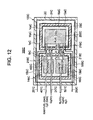
- FIG. 11 is a block diagram showing portable electronic equipment 1000 C including a reaction device 300 C where a fuel cell (reactor) 200 C, a reformer (reactor) 400 C, and a catalyst combustor (reactor) 500 C are housed in a heat insulating container 100 C
- FIG. 12 is a schematic cross sectional view showing an internal structure of the reaction device 300 C mounted in the electronic equipment 1000 C.
- a fuel cell 200 C is a solid oxide type fuel cell.
- a heat insulating container 100 C includes a first container 1 a C to house the solid oxide type fuel cell 200 C and a second container 1 b C to house a reformer 400 C and a catalyst combustor 500 C, and these two first containers 1 a C, 1 b C are housed in the second container 2 C.
- An atmospheric pressure in a space 23 C between the two first containers 1 a C, 1 b C and the second container 2 C is allowed to be lower than a normal atmospheric pressure.
- the reformer 400 C and the fuel cell 200 C are connected to each other with a fuel feeding tube 215 C, and the catalyst combustor 500 C and the fuel cell 200 C are connected to each other with a fuel discharging tube 216 C and an oxygen discharging tube 218 C.
- An oxygen feeding tube 217 C which is connected to an air pump (not shown) and supplies an air including oxygen to the fuel cell 200 C, and an oxygen feeding flow path (not shown), are communicated with a space 13 a C between the first container 1 a C and the fuel cell 200 C as the second embodiment, and the oxygen feeding tube 217 C, the oxygen feeding flow path and the space 13 a C share the air.
- the first containers 1 a C, 1 b C and the second container 2 C are same as those of the solid oxide type fuel cell 200 , the first container 1 and the second container 2 according to the first embodiment described above, and since the reformer 400 C and the catalyst combustor 500 C are same as the reformer 400 A and the catalyst combustor 500 A, alphabetic characters C, and alphabetic characters aC, bC for the first container 1 a C, 1 b C, are added to same reference numbers, and an explanation about the same configuration is omitted.
- FIG. 13 is a block diagram showing portable electronic equipment 1000 E including a reaction device 300 E where a fuel cell (reactor) 200 E, a reformer (reactor) 400 E, and a catalyst combustor (reactor) 500 E are housed in a heat insulating container 10 E
- FIG. 14 is a schematic cross sectional view showing an internal structure of the reaction device 300 E mounted in the electronic equipment 1000 E.
- Variation 4 A difference of Variation 4 from above-described Variation 3 is that a first container to house the reformer 400 C and the catalyst combustor 500 C is not provided.
- each reference number of corresponding configurations in FIGS. 11 and 12 is used by replacing trailing character “C” with “E”, and an explanation about the corresponding configurations is omitted.
- a reaction device 300 E of Variation 4 includes a first container 1 E to house the solid oxide type fuel cell 200 E and a second container 2 E to house the first container 1 E, the reformer 400 E and the catalyst combustor 500 E, and an atmospheric pressure in a space 23 E between the first container 1 E, the reformer 400 E and the catalyst combustor 500 E, and the second container 2 E, is allowed to be lower than the normal atmospheric pressure.
- the reformer 400 E and the solid oxide type fuel cell 200 E are connected to each other with a fuel feeding tube 215 E, and the catalyst combustor 500 E and the solid oxide type fuel cell 200 E are connected to each other with a fuel discharging tube 216 E and an oxygen discharging tube 218 E.
- An oxygen feeding tube 217 E which is connected to an air pump (not shown) and supplies an air including oxygen to the solid oxide type fuel cell 200 E, and an oxygen feeding flow path 207 E (not shown) of the fuel cell 200 E, are communicated with a space 13 E between the first container 1 E and the solid oxide type fuel cell 200 E, and the fuel feeding tube 215 E which is connected to a pump 700 E and supplies a reformed gas to the fuel cell 200 E is connected to a fuel feeding flow path 205 E (not shown) of the fuel cell 200 E.
- the reaction device 300 E and the electronic equipment 1000 E of Variation 4 have same advantages as above-described Variation 2. Specifically, the reaction device 300 E and the electronic equipment 1000 E of Variation 4 are not provided with the first container to house the reaction device the temperature rising time of which is shorter and which has lower temperature, and are provided with the first container to house the reaction device the temperature rising time of which is longer and which has higher temperature. Thus, as in the above-described Variation 2, since the first container to house the reformer 400 E and the catalyst combustor 500 E is not provided, it is possible to reduce the number of components, and thereby process yield can be improved, in addition to preventing the heat quantity of the reaction area from increasing, and accelerating heat rising time.
- the oxygen feeding flow paths 207 B, 207 C and 207 E and the oxygen feeding tubes 217 B, 217 C and 217 E of the fuel cells 200 B, 200 C and 200 E housed in the first containers 1 B, 1 a C and 1 E are communicated with the spaces 13 B, 13 a C and 13 E between the first containers 1 B, 1 a C and 1 E and the fuel cells 200 B, 200 C and 200 E, but the configurations are not limited to the above configurations. For example, as shown in FIGS.
- a fuel feeding flow path 205 F (not shown) of a fuel cell 200 F housed in a first container 1 F may be communicated with a space 13 F between the first container 1 F and the fuel cell 200 F, a fuel feeding tube 215 F may be communicated with the space 13 F of the first container 1 F without being directly connected to the fuel feeding flow path 205 F, and an oxygen feeding tube 217 F may be directly communicated with an oxygen feeding flow path 207 F (not shown).
- the fuel cells 200 A, 200 C are housed in one of the first containers laA, 1 a C
- the reformers 400 A, 400 C and the catalyst combustors 500 A, 500 C are housed in the other of the first containers 1 b A, 1 b C
- these two first containers laA, 1 b A or 1 a C, 1 b C are housed in the second containers 2 A, 2 C respectively.
- the configurations are not limited to the above configurations.
- the configuration where a plurality of reactors are housed in one of the first containers, and the first container is housed in the second container may be adopted.
- the number of the reactors and the first containers may be appropriately changed.
- the reactors to be housed are not limited to reactors of different functions, and may be reactors of same functions. Incidentally, same modification is possible also in Variation 2 and Variation 4.
- the present invention may be applied to not only a solid oxide type fuel cell, but also a polymer electrolyte fuel cell, a molten carbonate fuel cell, and the like.
Abstract
Description
O2+4e−→2O2− (1)
H2+O2−→H2O+2e 2− (2)
CO+O2−→CO2+2e2− (3)
P 0 +P LOSS −P<Δ and (1/α)P−P 0<Δ (4)
For example, when the gas is injected at the temperature TL, a gas having a pressure of the range shown with a two-headed arrow may be injected. This can be represented by the following formula (5).
P 0 +P LOSS −Δ<P<α(P 0+Δ) (5)
α(2P 0 +P LOSS)/(1+α) (6)
{(1−α)P 0 +P LOSS}/(1+α) (7)
Ra=gβρC P ΔTd/vk (8)
d<<{(1708)vk/[gρC P(ΔT/T)]}1/3
CH3OH+H2O→3H2+CO2 (9)
H2+CO2→H2O+CO (10)
H2+O2−→H2O+2e− (11)
CO+O2−→CO2+2e− (12)
½O2+2e−→O2− (13)
Claims (2)
Applications Claiming Priority (2)
| Application Number | Priority Date | Filing Date | Title |
|---|---|---|---|
| JP2007324645A JP4678025B2 (en) | 2007-12-17 | 2007-12-17 | Reaction apparatus and electronic equipment |
| JP2007-324645 | 2007-12-17 |
Publications (2)
| Publication Number | Publication Date |
|---|---|
| US20090155646A1 US20090155646A1 (en) | 2009-06-18 |
| US8641979B2 true US8641979B2 (en) | 2014-02-04 |
Family
ID=40404473
Family Applications (1)
| Application Number | Title | Priority Date | Filing Date |
|---|---|---|---|
| US12/333,486 Expired - Fee Related US8641979B2 (en) | 2007-12-17 | 2008-12-12 | Reaction device and electronic equipment |
Country Status (6)
| Country | Link |
|---|---|
| US (1) | US8641979B2 (en) |
| EP (1) | EP2073298A1 (en) |
| JP (1) | JP4678025B2 (en) |
| KR (1) | KR101005999B1 (en) |
| CN (1) | CN101465437B (en) |
| TW (1) | TWI389385B (en) |
Cited By (1)
| Publication number | Priority date | Publication date | Assignee | Title |
|---|---|---|---|---|
| US11441825B2 (en) * | 2019-01-11 | 2022-09-13 | Honeywell International Inc. | Nano-porous based thermal enclosure with heat removal |
Families Citing this family (14)
| Publication number | Priority date | Publication date | Assignee | Title |
|---|---|---|---|---|
| TW200824176A (en) * | 2006-11-30 | 2008-06-01 | Univ Yuan Ze | Sensing device of slim type |
| US20090246576A1 (en) * | 2008-03-27 | 2009-10-01 | Casio Computer Co., Ltd. | Reaction device and electronic equipment |
| FI20085721L (en) * | 2008-07-10 | 2010-01-11 | Waertsilae Finland Oy | Method and arrangement for improving the thermal efficiency of a fuel cell system |
| TWI390104B (en) * | 2010-03-04 | 2013-03-21 | Nat Univ Tsing Hua | Thermally activated electrochemical-catalytic converter for exhaust emission control with power generation |
| EP2703341B1 (en) * | 2011-04-26 | 2018-03-07 | Panasonic Intellectual Property Management Co., Ltd. | Method of operating a hydrogen generator |
| JP6203481B2 (en) * | 2012-08-07 | 2017-09-27 | 株式会社Ti | Reagent pretreatment method for hydrogen generator |
| US9606587B2 (en) | 2012-10-26 | 2017-03-28 | Google Inc. | Insulator module having structure enclosing atomspheric pressure gas |
| US8861191B1 (en) | 2013-09-30 | 2014-10-14 | Google Inc. | Apparatus related to a structure of a base portion of a computing device |
| US9430006B1 (en) | 2013-09-30 | 2016-08-30 | Google Inc. | Computing device with heat spreader |
| WO2015150307A1 (en) * | 2014-04-04 | 2015-10-08 | Haldor Topsøe A/S | Adaptive insulation for soc stack system |
| US9442514B1 (en) | 2014-07-23 | 2016-09-13 | Google Inc. | Graphite layer between carbon layers |
| JP6765375B2 (en) | 2015-01-28 | 2020-10-07 | メディカル エンタープライゼス ディストリビューション、 エルエルシー | Insulated battery housing for sterilizable surgical instruments |
| JP6043885B1 (en) * | 2016-05-30 | 2016-12-14 | 東京瓦斯株式会社 | Fuel cell system |
| WO2018207843A1 (en) * | 2017-05-11 | 2018-11-15 | 日本化薬株式会社 | Ultraviolet curable resin composition for blue light blocking films and blue light blocking film using same |
Citations (17)
| Publication number | Priority date | Publication date | Assignee | Title |
|---|---|---|---|---|
| JPH10155667A (en) | 1996-12-02 | 1998-06-16 | Nippon Sanso Kk | Insulator material filled with low thermal conductivity gas |
| US20020081471A1 (en) | 2000-12-22 | 2002-06-27 | Keegan Kevin R. | Fuel cell system incorporating pressure control |
| US20020106540A1 (en) | 2001-01-24 | 2002-08-08 | Casio Computer Co., Ltd. | Power supply system, fuel pack constituting the system, and device driven by power generator and power supply system |
| US20030054215A1 (en) * | 2001-09-20 | 2003-03-20 | Honeywell International, Inc. | Compact integrated solid oxide fuel cell system |
| US20040043263A1 (en) | 2002-08-29 | 2004-03-04 | Casio Computer Co., Ltd. | Reformer, method for manufacturing the reformer, and power generation system |
| EP1416551A2 (en) | 2002-10-28 | 2004-05-06 | Hewlett-Packard Development Company, L.P. | Protective container with preventative agent therein |
| JP2004303695A (en) | 2003-04-01 | 2004-10-28 | Toshiba Corp | High temperature body housing device |
| JP2005225686A (en) | 2004-02-10 | 2005-08-25 | Kyocera Corp | Vessel for housing fuel reformer and fuel reforming device |
| WO2006057158A1 (en) | 2004-11-26 | 2006-06-01 | Nissan Motor Co., Ltd. | Thermal insulating container for a heat generating unit of a fuel cell system |
| US20060127729A1 (en) | 2004-12-10 | 2006-06-15 | 3M Innovative Properties Company | Fuel cell |
| JP2007070184A (en) | 2005-09-08 | 2007-03-22 | Casio Comput Co Ltd | Reactor |
| CN1992411A (en) | 2005-12-28 | 2007-07-04 | 卡西欧计算机株式会社 | Reaction device, heat-insulating container, electricity generating device, and electronic apparatus |
| US20070151151A1 (en) | 2005-12-28 | 2007-07-05 | Casio Computer Co., Ltd. | Reaction device, heat-insulating container, fuel cell device, and electronic apparatus |
| GB2436396A (en) | 2006-03-24 | 2007-09-26 | Ceres Power Ltd | Fuel Cells Stack System Assembly |
| JP2008001579A (en) | 2006-06-26 | 2008-01-10 | Casio Comput Co Ltd | Reaction apparatus, power generation system using the same, and electronic instrument |
| WO2008095076A1 (en) | 2007-01-31 | 2008-08-07 | Modine Manufacturing Company | Fuel cell and method of operating the same |
| US20090246576A1 (en) | 2008-03-27 | 2009-10-01 | Casio Computer Co., Ltd. | Reaction device and electronic equipment |
Family Cites Families (7)
| Publication number | Priority date | Publication date | Assignee | Title |
|---|---|---|---|---|
| US6432567B1 (en) * | 1999-03-17 | 2002-08-13 | Sulzer Hexis Ag | Fuel cell battery with afterburning at the periphery of a cell stack |
| JP4696461B2 (en) * | 2004-03-31 | 2011-06-08 | ダイキン工業株式会社 | Solid oxide fuel cell |
| JP5055734B2 (en) * | 2005-09-27 | 2012-10-24 | カシオ計算機株式会社 | Fuel reformer for fuel cell |
| JP5013748B2 (en) * | 2006-05-23 | 2012-08-29 | 新光電気工業株式会社 | Solid oxide fuel cell |
| JP5040177B2 (en) * | 2006-05-31 | 2012-10-03 | カシオ計算機株式会社 | Microreactor, microreactor manufacturing method, power generation device using the microreactor, and electronic device |
| JP4636028B2 (en) * | 2007-01-24 | 2011-02-23 | カシオ計算機株式会社 | FUEL CELL DEVICE AND ELECTRONIC DEVICE |
| JP4258554B2 (en) * | 2007-02-02 | 2009-04-30 | カシオ計算機株式会社 | Sealing method for reformer |
-
2007
- 2007-12-17 JP JP2007324645A patent/JP4678025B2/en not_active Expired - Fee Related
-
2008
- 2008-12-01 KR KR1020080120368A patent/KR101005999B1/en not_active IP Right Cessation
- 2008-12-09 EP EP08021404A patent/EP2073298A1/en not_active Ceased
- 2008-12-12 US US12/333,486 patent/US8641979B2/en not_active Expired - Fee Related
- 2008-12-15 TW TW097148689A patent/TWI389385B/en not_active IP Right Cessation
- 2008-12-16 CN CN2008101859021A patent/CN101465437B/en not_active Expired - Fee Related
Patent Citations (23)
| Publication number | Priority date | Publication date | Assignee | Title |
|---|---|---|---|---|
| JPH10155667A (en) | 1996-12-02 | 1998-06-16 | Nippon Sanso Kk | Insulator material filled with low thermal conductivity gas |
| US20020081471A1 (en) | 2000-12-22 | 2002-06-27 | Keegan Kevin R. | Fuel cell system incorporating pressure control |
| US20020106540A1 (en) | 2001-01-24 | 2002-08-08 | Casio Computer Co., Ltd. | Power supply system, fuel pack constituting the system, and device driven by power generator and power supply system |
| US20030054215A1 (en) * | 2001-09-20 | 2003-03-20 | Honeywell International, Inc. | Compact integrated solid oxide fuel cell system |
| US20040043263A1 (en) | 2002-08-29 | 2004-03-04 | Casio Computer Co., Ltd. | Reformer, method for manufacturing the reformer, and power generation system |
| EP1416551A2 (en) | 2002-10-28 | 2004-05-06 | Hewlett-Packard Development Company, L.P. | Protective container with preventative agent therein |
| JP2004303695A (en) | 2003-04-01 | 2004-10-28 | Toshiba Corp | High temperature body housing device |
| JP2005225686A (en) | 2004-02-10 | 2005-08-25 | Kyocera Corp | Vessel for housing fuel reformer and fuel reforming device |
| US20070295734A1 (en) | 2004-11-26 | 2007-12-27 | Nissan Motor Co., Ltd. | Thermal Insulating Container for a Heat Generating Unit of a Fuel Cell System |
| WO2006057158A1 (en) | 2004-11-26 | 2006-06-01 | Nissan Motor Co., Ltd. | Thermal insulating container for a heat generating unit of a fuel cell system |
| JP2006156011A (en) | 2004-11-26 | 2006-06-15 | Nissan Motor Co Ltd | Heat-insulated container |
| US20060127729A1 (en) | 2004-12-10 | 2006-06-15 | 3M Innovative Properties Company | Fuel cell |
| JP2007070184A (en) | 2005-09-08 | 2007-03-22 | Casio Comput Co Ltd | Reactor |
| CN1992411A (en) | 2005-12-28 | 2007-07-04 | 卡西欧计算机株式会社 | Reaction device, heat-insulating container, electricity generating device, and electronic apparatus |
| US20070151151A1 (en) | 2005-12-28 | 2007-07-05 | Casio Computer Co., Ltd. | Reaction device, heat-insulating container, fuel cell device, and electronic apparatus |
| JP2007179927A (en) | 2005-12-28 | 2007-07-12 | Casio Comput Co Ltd | Thermally insulated container |
| GB2436396A (en) | 2006-03-24 | 2007-09-26 | Ceres Power Ltd | Fuel Cells Stack System Assembly |
| JP2008001579A (en) | 2006-06-26 | 2008-01-10 | Casio Comput Co Ltd | Reaction apparatus, power generation system using the same, and electronic instrument |
| US20090202875A1 (en) | 2006-06-26 | 2009-08-13 | Casio Computer Co., Ltd. | Reaction device, and fuel cell device and electronic apparatus using the reaction device |
| US7622208B2 (en) | 2006-06-26 | 2009-11-24 | Casio Computer Co., Ltd. | Reaction device, and fuel cell device and electronic apparatus using the reaction device |
| WO2008095076A1 (en) | 2007-01-31 | 2008-08-07 | Modine Manufacturing Company | Fuel cell and method of operating the same |
| US20100062298A1 (en) | 2007-01-31 | 2010-03-11 | Jeroen Valensa | Fuel cell and method of operating the same |
| US20090246576A1 (en) | 2008-03-27 | 2009-10-01 | Casio Computer Co., Ltd. | Reaction device and electronic equipment |
Non-Patent Citations (7)
| Title |
|---|
| Chinese Office Action dated Dec. 10, 2010 (and English translation thereof) in counterpart Chinese Application No. 200810185902.1. |
| Extended European Search Report dated Apr. 6, 2009, 6 pages, issued in counterpart European Application No. EP 08021404.2-2119. |
| Japanese Office Action dated Oct. 20, 2009 and English translation thereof issued in counterpart Japanese Application No. JP 2007-324645. |
| Taiwanese Office Action dated May 17, 2012 (and English translat on thereof) in counterpart Taiwanese Application No. 097148689. |
| U.S. Appl. No. 12/410,626, filed Mar. 25, 2009; First Named Inventor: Tsutomu Terazaki; Title: "Reaction Device and Electronic Equipment". |
| U.S. Office Action dated Aug. 3, 2011 issued in related U.S. Appl. No. 12/410,626. |
| U.S. Office Action dated Jan. 12, 2012 issued in related U.S. Appl. No. 12/410,626. |
Cited By (1)
| Publication number | Priority date | Publication date | Assignee | Title |
|---|---|---|---|---|
| US11441825B2 (en) * | 2019-01-11 | 2022-09-13 | Honeywell International Inc. | Nano-porous based thermal enclosure with heat removal |
Also Published As
| Publication number | Publication date |
|---|---|
| CN101465437A (en) | 2009-06-24 |
| KR20090065439A (en) | 2009-06-22 |
| US20090155646A1 (en) | 2009-06-18 |
| JP4678025B2 (en) | 2011-04-27 |
| TW200937720A (en) | 2009-09-01 |
| KR101005999B1 (en) | 2011-01-05 |
| TWI389385B (en) | 2013-03-11 |
| CN101465437B (en) | 2011-10-05 |
| EP2073298A1 (en) | 2009-06-24 |
| JP2009142778A (en) | 2009-07-02 |
Similar Documents
| Publication | Publication Date | Title |
|---|---|---|
| US8641979B2 (en) | Reaction device and electronic equipment | |
| JP3941632B2 (en) | Reformer, reformer manufacturing method and power generation system | |
| JP4508212B2 (en) | Reaction apparatus and electronic equipment | |
| CN101447581A (en) | Fuel reforming apparatus and fuel cell system | |
| JP5251204B2 (en) | Power generation system and method for stopping power generation system | |
| US20090202875A1 (en) | Reaction device, and fuel cell device and electronic apparatus using the reaction device | |
| JP4407681B2 (en) | FUEL CELL DEVICE AND ELECTRONIC DEVICE EQUIPPED WITH THE SAME | |
| WO2009038019A1 (en) | Fuel cell device and electronic equipment using fuel cell device | |
| JP2002358997A (en) | Solid oxide fuel cell stack | |
| JP2007176760A (en) | Reactor and method for producing reactor | |
| CN101409350B (en) | Fuel cell unit and electronic device | |
| JP5071454B2 (en) | Fuel cell device | |
| US20080176119A1 (en) | Fuel cell device and electronic equipment | |
| JP2007115677A (en) | Thin plate multilayer type hydrogen fuel battery | |
| JP5186974B2 (en) | Power generation system and method for stopping power generation system | |
| JP5396718B2 (en) | POWER GENERATION DEVICE, ITS CONTROL DEVICE, OPERATION METHOD, AND ELECTRONIC DEVICE | |
| JP5286824B2 (en) | Power generation device and electronic device | |
| JP4978216B2 (en) | Reactor heating device, reactor, fuel cell device and electronic equipment | |
| JP4258554B2 (en) | Sealing method for reformer | |
| US20080171245A1 (en) | Heat radiation preventing film, reaction device, fuel cell device, electronic equipment, heat reflecting film, and heat insulating container | |
| US7479340B2 (en) | Method for the production of electrochemical cells and an electrochemical cell stack | |
| JP4311430B2 (en) | FUEL CELL DEVICE AND ELECTRONIC DEVICE EQUIPPED WITH THE SAME |
Legal Events
| Date | Code | Title | Description |
|---|---|---|---|
| AS | Assignment |
Owner name: CASIO COMPUTER CO., LTD., JAPAN Free format text: ASSIGNMENT OF ASSIGNORS INTEREST;ASSIGNORS:ENDO, MOTOKI;TERAZAKI, TSUTOMU;ISHIKAWA, TETSUSHI;AND OTHERS;REEL/FRAME:021970/0833;SIGNING DATES FROM 20081031 TO 20081115 Owner name: CASIO COMPUTER CO., LTD., JAPAN Free format text: ASSIGNMENT OF ASSIGNORS INTEREST;ASSIGNORS:ENDO, MOTOKI;TERAZAKI, TSUTOMU;ISHIKAWA, TETSUSHI;AND OTHERS;SIGNING DATES FROM 20081031 TO 20081115;REEL/FRAME:021970/0833 |
|
| FEPP | Fee payment procedure |
Free format text: PAYOR NUMBER ASSIGNED (ORIGINAL EVENT CODE: ASPN); ENTITY STATUS OF PATENT OWNER: LARGE ENTITY |
|
| CC | Certificate of correction | ||
| FEPP | Fee payment procedure |
Free format text: MAINTENANCE FEE REMINDER MAILED (ORIGINAL EVENT CODE: REM.) |
|
| LAPS | Lapse for failure to pay maintenance fees |
Free format text: PATENT EXPIRED FOR FAILURE TO PAY MAINTENANCE FEES (ORIGINAL EVENT CODE: EXP.) |
|
| STCH | Information on status: patent discontinuation |
Free format text: PATENT EXPIRED DUE TO NONPAYMENT OF MAINTENANCE FEES UNDER 37 CFR 1.362 |
|
| FP | Lapsed due to failure to pay maintenance fee |
Effective date: 20180204 |