US8646215B2 - Flush glass assembly interfaces - Google Patents
Flush glass assembly interfaces Download PDFInfo
- Publication number
- US8646215B2 US8646215B2 US13/227,514 US201113227514A US8646215B2 US 8646215 B2 US8646215 B2 US 8646215B2 US 201113227514 A US201113227514 A US 201113227514A US 8646215 B2 US8646215 B2 US 8646215B2
- Authority
- US
- United States
- Prior art keywords
- glass
- glass piece
- piece
- guide
- guiding
- Prior art date
- Legal status (The legal status is an assumption and is not a legal conclusion. Google has not performed a legal analysis and makes no representation as to the accuracy of the status listed.)
- Active, expires
Links
Images


Classifications
-
- E—FIXED CONSTRUCTIONS
- E06—DOORS, WINDOWS, SHUTTERS, OR ROLLER BLINDS IN GENERAL; LADDERS
- E06B—FIXED OR MOVABLE CLOSURES FOR OPENINGS IN BUILDINGS, VEHICLES, FENCES OR LIKE ENCLOSURES IN GENERAL, e.g. DOORS, WINDOWS, BLINDS, GATES
- E06B7/00—Special arrangements or measures in connection with doors or windows
- E06B7/16—Sealing arrangements on wings or parts co-operating with the wings
- E06B7/22—Sealing arrangements on wings or parts co-operating with the wings by means of elastic edgings, e.g. elastic rubber tubes; by means of resilient edgings, e.g. felt or plush strips, resilient metal strips
- E06B7/23—Plastic, sponge rubber, or like strips or tubes
- E06B7/2305—Plastic, sponge rubber, or like strips or tubes with an integrally formed part for fixing the edging
- E06B7/2307—Plastic, sponge rubber, or like strips or tubes with an integrally formed part for fixing the edging with a single sealing-line or -plane between the wing and the part co-operating with the wing
-
- B—PERFORMING OPERATIONS; TRANSPORTING
- B60—VEHICLES IN GENERAL
- B60J—WINDOWS, WINDSCREENS, NON-FIXED ROOFS, DOORS, OR SIMILAR DEVICES FOR VEHICLES; REMOVABLE EXTERNAL PROTECTIVE COVERINGS SPECIALLY ADAPTED FOR VEHICLES
- B60J1/00—Windows; Windscreens; Accessories therefor
- B60J1/08—Windows; Windscreens; Accessories therefor arranged at vehicle sides
- B60J1/12—Windows; Windscreens; Accessories therefor arranged at vehicle sides adjustable
- B60J1/16—Windows; Windscreens; Accessories therefor arranged at vehicle sides adjustable slidable
- B60J1/17—Windows; Windscreens; Accessories therefor arranged at vehicle sides adjustable slidable vertically
-
- B—PERFORMING OPERATIONS; TRANSPORTING
- B60—VEHICLES IN GENERAL
- B60J—WINDOWS, WINDSCREENS, NON-FIXED ROOFS, DOORS, OR SIMILAR DEVICES FOR VEHICLES; REMOVABLE EXTERNAL PROTECTIVE COVERINGS SPECIALLY ADAPTED FOR VEHICLES
- B60J10/00—Sealing arrangements
- B60J10/70—Sealing arrangements specially adapted for windows or windscreens
- B60J10/74—Sealing arrangements specially adapted for windows or windscreens for sliding window panes, e.g. sash guides
- B60J10/79—Sealing arrangements specially adapted for windows or windscreens for sliding window panes, e.g. sash guides for flush-glass windows, i.e. for windows flush with the vehicle body or the window frame
-
- B—PERFORMING OPERATIONS; TRANSPORTING
- B60—VEHICLES IN GENERAL
- B60J—WINDOWS, WINDSCREENS, NON-FIXED ROOFS, DOORS, OR SIMILAR DEVICES FOR VEHICLES; REMOVABLE EXTERNAL PROTECTIVE COVERINGS SPECIALLY ADAPTED FOR VEHICLES
- B60J5/00—Doors
- B60J5/04—Doors arranged at the vehicle sides
-
- B—PERFORMING OPERATIONS; TRANSPORTING
- B60—VEHICLES IN GENERAL
- B60J—WINDOWS, WINDSCREENS, NON-FIXED ROOFS, DOORS, OR SIMILAR DEVICES FOR VEHICLES; REMOVABLE EXTERNAL PROTECTIVE COVERINGS SPECIALLY ADAPTED FOR VEHICLES
- B60J5/00—Doors
- B60J5/04—Doors arranged at the vehicle sides
- B60J5/0401—Upper door structure
- B60J5/0402—Upper door structure window frame details, including sash guides and glass runs
Definitions
- the present invention generally relates to an automobile glass window interface.
- automotive glass window systems include one or more windows that are moveable in a substantially vertical direction.
- attempts have been made to eliminate the inboard offset of such glass windows.
- Complete elimination of the offset is known as pursuing a substantially “flush” relationship between the glass windows with the adjacent body and trim surfaces.
- a glass guiding system is desired having the aforementioned advantages and solving and/or making improvements on the aforementioned disadvantages.
- a glass guiding system comprising first and second glass pieces, each having an inboard surface, a front edge and a rear edge.
- the system also includes a first guiding assembly comprising a guide bonded to the inboard surface of the first piece and a retaining structure having a channel to slideably retain the guide, wherein the rear edge of the first piece and the front edge of the second piece engage when the first piece is fully raised.
- a glass guiding and stabilization system includes a front glass piece within a vehicle door, wherein the front glass piece includes an inboard surface and a rear edge, wherein the front glass piece is movable between a lowered position and a raised position, wherein the front glass piece moves slightly rearward as the front glass piece is moved from the lowered position to the raised position.
- the system also includes a rear glass piece, wherein the rear glass piece includes an inboard surface and a front edge, wherein the rear glass piece is movable between a lowered position and a raised position, wherein the rear glass piece moves slightly forward as the rear glass piece is moved from the lowered position to the raised position.
- the system further includes a first guiding assembly comprising a first glass guide bonded to the inboard surface of the front glass piece proximate the rear edge of the front glass piece and a first retaining structure having a first channel, wherein the first channel includes a first seal that is configured to slideably retain the first glass guide; and wherein the rear edge of the front glass piece and the front edge of the rear glass piece are in direct engagement when both the front and rear glass pieces are in the raised positions.
- a glass guiding and stabilization system comprising a front glass piece within a vehicle door, wherein the front glass piece includes an inboard surface, an outboard surface and a rear edge, wherein the front glass piece is movable between a lowered position and a raised position.
- the system also includes a rear glass piece, wherein the rear glass piece includes an inboard surface, an outboard surface and a front edge, and wherein a margin is between the front edge of the rear glass piece and the rear edge of the front glass piece when the front glass piece is in the raised position.
- the system further includes a first glass guiding assembly comprising a glass guide bonded to the inboard surface of the front glass piece and a retaining structure having a channel, wherein the channel includes a seal that is configured to slideably retain the glass guide.
- FIG. 1 is a front perspective view of a first embodiment of an automobile having a flush glass assembly
- FIG. 2 is an elevated side view of the automobile with a front side door in an open position
- FIG. 2A is an enlarged view of section IIA in FIG. 2 showing the top and rear side of a glass window;
- FIG. 3 is a rear perspective view of the automobile
- FIG. 4 is a side view of a daylight opening module that is employed in a vehicle side door
- FIG. 4A is a side view of the daylight opening module without a top component
- FIG. 4B is a side view of the daylight opening module having retaining structures that extend below a belt line of the automobile door;
- FIG. 5 is a top cross-sectional view taken through line V-V of FIG. 2A illustrating a glass window retaining structure
- FIG. 6 is a top cross-sectional view of the glass window retaining structure, according to another embodiment.
- FIG. 7 is a cross-sectional view taken through an oval-shaped glass guide, according to another embodiment.
- FIG. 8 is a cross-sectional view taken through a rectangular-shaped glass guide, according to a further embodiment
- FIG. 8A is a cross-sectional view taken through a tapered glass guide, according to a further embodiment
- FIG. 9 is a side view of a rear daylight opening module that may be used in a vehicle rear door
- FIG. 9A is a side view of the rear daylight opening module without a top component
- FIG. 10 is a top cross-sectional view taken through line X-X of FIG. 2 , illustrating a rear glass window retaining structure
- FIG. 11 is a top cross-sectional view taken through line XI-XI of FIG. 3 , illustrating the front and rear glass window retaining structures;
- FIG. 12 is a front perspective view of a second embodiment of an automobile having a flush glass assembly
- FIG. 13 is a side elevational view of the second embodiment of the automobile shown in
- FIG. 12 with a door in an open position
- FIG. 13A is an enlarged view of section XIIIA of FIG. 13 illustrating a top and rear side of a glass window;
- FIG. 14 is a rear perspective view of the automobile shown in FIG. 13 ;
- FIG. 15 is a top view of a glass window retaining structure for the flush glass assembly of the second embodiment of the automobile.
- FIG. 16 is a sealing arrangement for sealing two flush glass windows, according to a first embodiment
- FIG. 17 is a sealing arrangement for sealing two flush glass windows, according to a second embodiment
- FIG. 18 is a sealing arrangement for sealing two flush glass windows, according to a third embodiment.
- FIG. 18A is a sealing arrangement, according to a fourth embodiment.
- FIG. 19 is a side elevational view of a front door of the automobile having a lower door frame
- FIG. 20 is a top plan view of the lower door frame
- FIG. 21 is a side elevational view of the front and rear side doors
- FIG. 22 is a top cross-sectional view taken through lines XXII-XXII of FIG. 21 illustrating the glass window retaining structure disposed within the lower door frame, according to one embodiment
- FIG. 22A is a top cross-sectional view of the glass window retaining structure disposed within the lower door frame, according to another embodiment
- FIG. 23 is a top cross-sectional view of the glass window retaining structure disposed within the lower door frame, according to another embodiment
- FIG. 24 is a front elevational view of a side mirror assembled to the daylight opening module.
- FIG. 25 is a side elevational view of the lower door frame and the daylight opening module.
- the terms “upper,” “lower,” right,” “left,” “rear,” “front,” “vertical,” “horizontal,” and derivatives thereof shall relate to the present invention as oriented in FIG. 1 .
- the invention may assume various alternative orientations, except where expressly specified to the contrary.
- the specific devices and processes illustrated in the attached drawings, and described in the following specification are simply exemplary embodiments of the inventive concepts defined in the appended claims. Hence, specific dimensions and other physical characteristics relating to the embodiments disclosed herein are not to be considered as limiting, unless the claims expressly state otherwise.
- reference numeral 1 generally designates an automobile (automotive vehicle) flush glass assembly 11 having a glass guiding and stabilization system 10 .
- the assembly 11 comprises a first glass piece 12 , a second glass piece 14 , and a quarter glass piece 58 , where each glass piece 12 , 14 , 58 includes an inboard surface 48 , an outboard surface 50 , a front edge 56 , and a rear edge 54 .
- Each glass piece 12 , 14 , 58 may be moveable or fixed.
- One or all of the glass pieces 12 , 14 , 58 may be door window panes (panels) that, when moveable, may be actuated or manually actuated.
- the movement of the glass pieces 12 , 14 , 58 is in a substantially vertical direction and closes out a daylight opening of the vehicle.
- the first glass piece 12 , the second glass piece 14 , and/or a quarter glass piece 58 may be articulated or rotated into a drop position.
- the first and second glass pieces 12 , 14 are each operably connected to a first and second door 22 , 24 , respectively, where each glass piece 12 , 14 rotates in conjunction with the first and second doors 22 , 24 , respectively, about door hinges.
- the quarter glass piece 58 is operably connected to the second door 24 .
- Each glass piece 12 , 14 , 58 may be constructed of any glass type suited for automobile application. Examples include tempered, laminated, acoustic laminated, ion exchange thin glass, and may include privacy tinting.
- the glass guiding and stabilization system 10 provides for a flush glass assembly 11 in which the glass pieces 12 , 14 , 58 are in a single plane with outer surfaces of various adjacent vehicle doors and body components.
- the first object 20 Located adjacent the front edge 56 ( FIG. 4 ) of the first glass piece 12 is a first object 20 that includes an outboard surface 21 .
- the first object 20 may comprise a number of automotive components including, but not limited to, a mirror sail cover, a trim appliqué, belts, interior or exterior trim, badging, etc.
- the first object 20 may be an individual component or may be part of an integrated, single-unit daylight opening module 16 , which will be described in detail below.
- the flush glass assembly 11 may include more than one daylight opening module 16 , typically dependent on the number of doors presents, or in other words, the number of daylight openings being integrated into the flush appearance, but this will ultimately depend upon the suitable number for the particular application.
- the second object may comprise a number of automotive components, including the second glass piece 14 . Additionally, the second object that is located immediately adjacent the rear edge 54 of the first glass piece 12 may comprise a buffer between the first glass piece 12 and the second glass piece 14 .
- the buffer may be mounted to one or both of the doors 22 , 24 , the automobile body side, or the daylight opening module 16 .
- Such a buffer may take the form of a number of components including, but not limited to, an appliqué 32 or simply a sealing component residing between the first glass piece 12 and the second glass piece 14 .
- the second object includes an outboard surface, as is the case with the first glass piece 12 , the second glass piece 14 , and the first object 20 .
- the outboard surfaces 50 , 21 of the glass pieces 12 , 14 , the first object 20 , and the second object are all in a single plane, giving all of these components 12 , 14 , 20 , 32 , a flush appearance.
- One or more of the outboard surfaces 50 , 21 may be tuned to have an over flush appearance to adjust for wind noise performance. This may also be true for the quarter glass piece 58 . Additionally, the automobile header may be flush with the components.
- the second glass piece 14 has objects located immediately adjacent the front edge 56 and the rear edge 54 .
- Immediately adjacent the front edge 56 of the second glass piece 14 is either the first glass piece 12 or the buffer between the first and second glass pieces 12 , 14 , as described above.
- the buffer may take the form of several alternative components and may be mounted to one or both of the doors 22 , 24 , the body side of the automobile body side, or the daylight opening module 16 .
- the buffer may be an appliqué 32 or a seal of various embodiments. Such various sealing embodiments are illustrated in FIGS. 16-18A .
- the seals may be made of various materials, including thermoplastic vulcanizates (TPVs), thermoplastic polyurethanes (TPUs), thermoplastic polyolefins (TPOs), ethylene propylene diene monomers (EPDMs), etc.
- TPVs thermoplastic vulcanizates
- TPUs thermoplastic polyurethanes
- TPOs thermoplastic polyolefins
- EPDMs ethylene propylene diene monomers
- Located immediately adjacent the rear edge 54 of the second glass piece 14 is one of various components, including but not limited to, the fixed glass piece 58 or a buffer between the second glass piece 14 and the fixed glass piece 58 .
- the buffer may be a channel, an appliqué and/or a sealing component.
- an outboard surface 60 of the fixed glass piece 58 and/or an outboard surface of the buffer between the second glass piece 14 and the fixed glass piece 58 , as well as the outboard surface 50 of the second glass piece 14 are all oriented in a single plane when the second door 24 is in a closed position.
- the illustrated glass guiding and stabilization system 10 comprises an arrangement having the appliqué 32 disposed between the first glass piece 12 and the second glass piece 14 .
- this component is more generally a retaining structure 32 that may be made of a number of materials, including but not limited to metal, plastic or an acrylic.
- the retaining structure 32 is part of a larger component that is generally described as the daylight opening module 16 for retaining components, which are described in detail below, that provide guidance and stability for movement of the glass pieces 12 , 14 , 58 .
- the daylight opening module 16 may take on various embodiments ( FIGS. 4 , 4 A, 4 B, 9 and 9 A) depending on the application of use, thereby providing design and manufacturing flexibility.
- Embodiments shown without a top component may be particularly useful for convertibles.
- the daylight opening module 16 may comprise a single molded or extruded piece or a plurality of components and is operably connected to the first or second door 22 , 24 .
- the joining of the components may be accomplished by welding, including sonic welding, mechanically fastening, chemically bonding, an adhesive, and tape, among other assembly methods.
- the assembly method of the daylight opening module 16 to the first or second door 22 , 24 will be described in detail below.
- the illustrated retaining structure 32 is oriented in a substantially vertical direction and corresponds substantially with the rear edge 54 of the first glass piece 12 .
- the retaining structure 32 includes a channel 34 that extends in a substantially vertical direction within the retaining structure 32 .
- the channel 34 may be of any number of geometric configurations and within the channel 34 is disposed a seal 36 .
- the disposal of the seal 36 within the channel 34 may be accomplished by an adhesive or mechanically fastening the seal 36 therein.
- the seal 36 may be extruded or molded (including multi-shot molding process) and may be made of various materials including, but not limited to thermoplastic vulcanizates (TPVs), thermoplastic polyurethanes (TPUs), thermoplastic polyolefins (TPOs), ethylene propylene diene monomers (EPDMs), etc.
- the seal 36 comprises an outer surface 70 that is at least partially in contact with the retaining structure channel 34 and also an inner surface 72 .
- the cavity formed by the inner surface 72 may take on any number of geometries and most, if not all, of the inner surface 72 is coated with a low friction substance 38 , according to one embodiment.
- the low friction substance 38 may be approximately 50 micrometers ( ⁇ m) of Tokiwa or a similar coating having a low friction coefficient, but it is conceivable that the substance 38 thickness could range from approximately 4 micrometers ( ⁇ m) to approximately 6 millimeters (mm).
- a glass guide 40 is comprised of a body portion 44 and an engagement section 42 .
- the engagement section 42 is disposed within the seal 36 , and more specifically within the coating 38 on the inner surface 72 of the seal 36 .
- the engagement section 42 is formed of a geometry corresponding to the geometry of the cavity formed by the inner surface 72 of the seal 36 . As noted above, these corresponding geometries may be any number of geometries including, but not limited to, an oval shape 74 ( FIG. 7 ) or a rectangular shape 76 ( FIG. 8 ) or a tapered shape 84 ( FIG. 8A ).
- the glass guide 40 is typically a plastic material, but it is conceivable that several other materials may be suitable.
- the glass guide 40 may optionally include a rigid insert 43 , such as metal, to provide additional structural integrity.
- a rigid insert 43 such as metal
- the body portion 44 extends in a plane substantially parallel to the inboard surface 48 of the first glass piece 12 .
- the body portion 44 of the glass guide 40 includes an inboard surface 78 and outboard surface 80 . At least part of the outboard surface 80 includes a bonding adhesive as well as an adhesion primer to ensure proper adhesion that securely engages the body portion 44 of the glass guide 42 to the inboard surface 48 of the first glass piece 12 .
- This secure engagement allows the glass guide 40 to travel in a substantially vertical direction with the first glass piece 12 as the first glass piece 12 moves up or down in a substantially vertical direction.
- the engagement section 42 of the glass guide 40 travels smoothly within the seal 36 and does not chuck or bind as a result of suitable controlled tolerances, and the presence of the low friction coating or other known material 38 within the inner surface 72 of the seal 36 .
- One or more sealing lips 45 may be employed to ensure continuous sealing between the inboard surface 48 of the glass piece 12 and the glass guide 40 , as well as optionally the retaining structure 32 .
- a frit material is included along the inboard surface 48 of the first glass piece 12 where the body portion 44 of the glass guide 40 is present.
- the retaining structure 32 may optionally include a rigidifying insert 52 to increase the structural integrity of the retaining structure 32 .
- This rigidifying structure 52 may be of various shapes, such as an I-beam shape, as illustrated in one embodiment, and may be of various materials, including metal according to other embodiments.
- the previously described retaining structure 32 was discussed in the context of associating with the rear edge 54 of the first glass piece 12 .
- a similar retaining structure 32 may be present proximate any edge of either the first or second glass piece 12 , 14 .
- such a retaining structure 32 may be present at the front edge 56 of the second glass piece 14 , the rear edge 54 of the second glass piece 14 , and/or the front edge 56 of the first glass piece 12 , in addition to the previously described position of the rear edge 54 of the first glass piece 12 .
- the key distinction between the various positioning of the retaining structure 32 pertains to orientation of the glass guide 40 .
- the glass guide 40 When positioned at a rear edge 54 , the glass guide 40 will extend away from the seal 36 towards the front of the vehicle, whereas when positioned at a front edge 56 of the first or second glass piece 12 , 14 , the glass guide 40 will extend away from the seal 36 towards the rear of the vehicle.
- the glass guiding and stabilization system 10 may be configured such that no structural object is disposed between the first and second glass pieces 12 , 14 , according to a second embodiment.
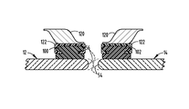
- the rear edge 54 of the first glass piece 12 comes into contact with the front edge 56 of the second glass piece 14 as shown in FIGS. 12-14 .
- a first guide 100 is bonded to the inboard surface 48 of the first glass piece 12 proximate the rear edge 56 of the first glass piece 12 .
- a second guide 102 is bonded to the inboard surface 48 of the second glass piece 14 proximate the front edge 56 of the second glass piece 14 .
- the bonding substance is similar to that described in the previous embodiment.
- the guides 100 , 102 slide within coated seals having a corresponding geometry to the seals 36 , 102 , as described in the previous embodiment.
- each glass piece 12 , 14 travels up and down in a substantially vertical direction between a raised and a lowered position, but this movement is not truly vertical. Instead, the first glass piece 12 moves slightly rearward, with respect to the vehicle, as the first glass piece 12 is moved from a lowered position to the raised position. Similarly, the second glass piece 14 moves slightly forward, with respect to the vehicle, as the second glass piece 14 is moved from a lowered position to the raised position. It is only when both glass pieces 12 , 14 are in the fully raised position that the rear edge 56 of the first glass piece 12 is in contact with the front edge 54 of the second glass piece 14 .
- the first and second glass pieces 12 , 14 are bonded to guides 100 , 102 , respectively, in a similar fashion as that described above, with respect to the bonding of the glass pieces 12 , 14 to glass guide 40 .
- the guides 100 , 102 slidably reside, at least in part, within channels 122 that are secured to the automobile body side metal 120 .
- the securing of the channels 122 to the metal 120 may be achieved by welding, bolting, riveting, etc. These are merely a few illustrative examples.
- the channels 122 may be secured to the aforementioned daylight opening module 16 .
- FIGS. 16-18 A third embodiment of the flush glass assembly 11 having the glass guiding and stabilization system 10 is shown in FIGS. 16-18 which does not include an appliqué 32 between the first and second glass pieces 12 , 14 , and instead merely has a flexible seal arrangement 200 disposed between the first and second glass pieces 12 , 14 . Additionally, and similar to previous embodiments, the first and second glass pieces 12 , 14 are bonded to guides 202 that slidably reside, at least in part, within channels 222 that are secured to the automobile body side metal 220 or a form of the daylight opening module 16 in a manner previously described.
- the seal arrangement 200 comprises a seal component 208 that extends from the guide 202 discussed above.
- the seal 208 is typically an extension of the guide 202 and closes out a small gap 204 between the first and second glass pieces 12 , 14 , while also sealing the gap 204 to prevent debris and air from entering the interior of the vehicle.
- the seal 208 will have an outboard surface 206 that is substantially parallel to the single plane formed by the outboard surfaces 50 of the first and second glass pieces 12 , 14 .
- the seal 208 ( FIG. 18 ) may optionally include a structural rigidifying insert 210 , depending on the particular application.
- a seal 208 is shown representing an embodiment having a buffer, such as an appliqué, between the first and second glass pieces 12 , 14 above the belt line, described in detail previously.
- a buffer such as an appliqué
- structural components have been omitted to more clearly represent an alternate sealing arrangement that includes the seals 208 positioned at extreme edges of the first and second glass pieces 12 , 14 .
- the illustrated embodiment shows two seals 208 employed to close out the gap 204 , but a single seal 208 may be mounted to the appliqué.
- Such an appliqué may include a flange that extends perpendicularly to the appliqué surface, in an inboard direction, having one or more locking features. The locking features function to engage gripping features present on the seal 208 .
- the first and second doors 22 , 24 each comprise a lower door frame 300 as seen in FIGS. 19-23 that includes an outer panel 302 and an inner panel 304 , with both the outer panel 302 and the inner panel 304 having a front edge 306 and a rear edge 308 .
- the lower door frame 300 will be described generally, but it is noted that the lower door frame 300 may take on any number of configurations to accommodate various automobile models, including sedans, coupes, convertibles, trucks, SUVs, crossovers, etc. The specific model will dictate, in part, the details of the lower door structure 300 components, with respect to geometry, arrangement, location, etc.
- a gap 310 is provided between the outer panel 302 and the inner panel 304 that is large enough to house the first or second glass piece 12 , 14 , respectively.
- the glass guide 40 is operably connected to the inboard surface 48 of the first or second glass piece 12 , 14 , with bonding being one example of such an operable connection.
- Also disposed between the outer panel 302 and the inner panel 304 is at least one retaining bracket 312 that comprises a channel 314 which is configured similar to the retaining structure 32 described above.
- the retaining bracket 312 and associated components may simply be an extension of the retaining structure 32 that was previously described in a configuration above the belt line of the door 22 , 24 . Such a configuration would allow the retaining bracket 312 to be assembled as part of the daylight opening module 16 .
- the retaining bracket 312 and/or the retaining structure 32 may be comprised of multiple pieces that are placed in spaced alignment or in a direct abutting alignment.
- the retaining bracket 312 may be secured to the lower door frame 300 at various locations, including the outer panel 302 , the inner panel 304 , the front edge 306 , and/or the rear edge 308 .
- the retaining bracket may be secured to the lower door frame 300 by welding, riveting, bolting, or by employing other mechanical fasteners.
- the retaining bracket 312 may be formed as part of the daylight opening module 16 that includes extensions 330 ( FIG. 4B ) that descend downwardly into the lower door frame 300 .
- the extent of the descension will depending on numerous factors, including the type of door, type of glass, whether the glass is moveable or fixed, etc.
- the channel 314 is sealed and is configured to slideably retain the glass guide 40 .
- the retaining bracket 312 is located proximate the rear edge 54 or the front edge 56 of the glass piece 12 .
- There may also be a plurality of retaining brackets 312 for example, having one retaining bracket 312 at each of the rear edge 308 and the front edge 306 .
- the retaining brackets 312 may be positioned at various locations within the lower door frame 300 , such as the front and rear edges 306 , 308 of the lower door frame 300 ( FIG. 22 ) or alternatively the inner panel ( FIG.
- the latter configuration may be particularly advantageous in an application that requires the glass pieces 12 , 14 , and/or 58 to be particularly close in proximity to one another, such as where the vehicle lacks an appliqué or other large buffer between glass pieces.
- the positioning of the retaining brackets 312 is dependent upon the desired position of the glass pieces 12 , 14 .
- the glass guide 40 may be bonded to the glass pieces 12 , 14 at any position to provide adjustability to the glass pieces 12 , 14 positioning.
- the upper door frame comprises a daylight opening module 16 that may be comprised of one or more components.
- these components may include exterior trim components including, but not limited to, belts, belt seals, exterior trim, appliqués, badging a header molding, mirror mounts, and a mirror.
- the daylight opening module 16 may include interior trim components including, but not limited to, garnish molding, an inner belt, and a mirror sail cover. It is conceivable that some or all of these components may be preassembled prior to installation of the door 22 and/or 24 on the automobile. Irrespective of which components make up the daylight opening module 16 , by preassembling some or all of the components, installation of the daylight opening module 16 is facilitated in an efficient manner with superior fit and finish improvements.
- the daylight opening module 16 may simply be mounted over the first glass piece 12 , the second glass piece 14 , and/or the quarter glass piece 58 . At least one portion of the daylight opening module 16 extends below the belt shelf and is mechanically fastened to the lower door frame 300 inner panel 304 and/or an extension of the outer panel 302 .
- the daylight opening module 16 may be configured to include a side view mirror assembly as shown in FIG. 24 , according to one embodiment. In the event the daylight opening module 16 does includes a mirror assembly 400 ( FIG. 24 ), the mirror assembly 400 may simply be installed prior to or during daylight opening module 16 installation.
- the mirror assembly 400 is not a component of the daylight opening module 16 and the mirror assembly 400 has been attached to the door metal prior to installation of the daylight opening module 16 .
- This attachment may be made by bolts, screws, clips, or any other suitable mechanical fastener 404 .
- the daylight opening module 16 includes an aperture 402 larger in area than that of the mirror 400 and is simply fit over the previously installed mirror assembly 400 .
- the mirror assembly 400 may include several components, including a mirror head 406 and a mirror sail mount 408 . Both the mirror head 406 and mirror sail mount 408 may be customized to various geometries to meet aerodynamic requirements and provide aesthetic design flexibility.
- the mirror assembly 400 is serviceable, while being integrated with the automobile body or the daylight opening module 16 .
- the system 10 components may be assembled individually or come in as an integrated daylight opening module 16 . Flexibility is provided by allowing the glass to be installed prior to module 16 installation or subsequent to module 16 installation. In the case of the glass being installed prior to module 16 installation, the module 16 may simply slide onto the glass guides 40 prior to moving the module 16 downward to attach the module to the lower door frame 300 . Conversely, installing the glass after installation of the module 16 allows the glass to simply “drop-in” to the flush glass assembly 11 .
- the glass guides 40 may already be bonded to the glass and lowered into the channel 34 of the retaining structure 32 , and more specifically within the seal 36 . Alternatively, it is conceivable that the glass guide 40 is bonded to the glass during or after dropping in the glass.
- the flush glass assembly 11 advantageously provides for a “flush” glass window arrangement for a vehicle, thereby decreasing wind noise heard by a vehicle occupant, while adequately sealing proximate glass window edges to prevent debris from entering the passenger area. Additionally, the glass guiding and stabilization system improves vehicle assembly methods by providing enhanced flexibility, while also alleviating assembly issues commonly associated with installation of doors, glass windows, and other associated components. Based on the aforementioned flexibility, all or a portion of the described invention may be employed in various other automobile applications, such as a moonroof assembly.
Abstract
A glass guiding system is provided comprising first and second glass pieces, each having an inboard surface, a front edge and a rear edge. The system also includes a first guiding assembly comprising a guide bonded to the inboard surface of the first piece and a retaining structure having a channel to slideably retain the guide, wherein the rear edge of the first piece and the front edge of the second piece engage when the first piece is fully raised.
Description
The present invention generally relates to an automobile glass window interface.
Generally, automotive glass window systems include one or more windows that are moveable in a substantially vertical direction. In order to improve both the aerodynamic and aesthetic characteristics of a vehicle, attempts have been made to eliminate the inboard offset of such glass windows. Complete elimination of the offset is known as pursuing a substantially “flush” relationship between the glass windows with the adjacent body and trim surfaces.
Previous attempts to obtain such a flush relationship have been stymied by inadequate guiding and sealing systems that allow the glass window to remain stable during the substantially vertical motion. Inadequate guiding and sealing systems cause the glass window to be prone to chucking while driving on rough road and binding during typical glass function cycling. Additional problems include glass “blow-out” due to wind flow vortex around the glass that causes a pressure differential and sucking of the glass outboard and away from the guiding and sealing system.
Accordingly, a glass guiding system is desired having the aforementioned advantages and solving and/or making improvements on the aforementioned disadvantages.
According to one aspect of the present invention, a glass guiding system is provided comprising first and second glass pieces, each having an inboard surface, a front edge and a rear edge. The system also includes a first guiding assembly comprising a guide bonded to the inboard surface of the first piece and a retaining structure having a channel to slideably retain the guide, wherein the rear edge of the first piece and the front edge of the second piece engage when the first piece is fully raised.
According to another aspect of the present invention, a glass guiding and stabilization system is provided. The system includes a front glass piece within a vehicle door, wherein the front glass piece includes an inboard surface and a rear edge, wherein the front glass piece is movable between a lowered position and a raised position, wherein the front glass piece moves slightly rearward as the front glass piece is moved from the lowered position to the raised position. The system also includes a rear glass piece, wherein the rear glass piece includes an inboard surface and a front edge, wherein the rear glass piece is movable between a lowered position and a raised position, wherein the rear glass piece moves slightly forward as the rear glass piece is moved from the lowered position to the raised position. The system further includes a first guiding assembly comprising a first glass guide bonded to the inboard surface of the front glass piece proximate the rear edge of the front glass piece and a first retaining structure having a first channel, wherein the first channel includes a first seal that is configured to slideably retain the first glass guide; and wherein the rear edge of the front glass piece and the front edge of the rear glass piece are in direct engagement when both the front and rear glass pieces are in the raised positions.
According to a further aspect of the present invention, a glass guiding and stabilization system is provided comprising a front glass piece within a vehicle door, wherein the front glass piece includes an inboard surface, an outboard surface and a rear edge, wherein the front glass piece is movable between a lowered position and a raised position. The system also includes a rear glass piece, wherein the rear glass piece includes an inboard surface, an outboard surface and a front edge, and wherein a margin is between the front edge of the rear glass piece and the rear edge of the front glass piece when the front glass piece is in the raised position. The system further includes a first glass guiding assembly comprising a glass guide bonded to the inboard surface of the front glass piece and a retaining structure having a channel, wherein the channel includes a seal that is configured to slideably retain the glass guide.
These and other aspects, objects, and features of the present invention will be understood and appreciated by those skilled in the art upon studying the following specification, claims, and appended drawings.
In the drawings:
As required, detailed embodiment(s) of the present invention are disclosed herein; however, it is to be understood that the disclosed embodiments are merely exemplary of the invention that may be embodied in various and alternative forms. The figures are not necessarily to a detailed design; some schematics may be exaggerated or minimized to show function overview. Therefore, specific structural and functional details disclosed herein are not to be interpreted as limiting, but merely as a representative basis for teaching one skilled in the art to variously employ the present invention.
For purposes of description herein, the terms “upper,” “lower,” right,” “left,” “rear,” “front,” “vertical,” “horizontal,” and derivatives thereof shall relate to the present invention as oriented in FIG. 1 . However, it is to be understood that the invention may assume various alternative orientations, except where expressly specified to the contrary. It is also to be understood that the specific devices and processes illustrated in the attached drawings, and described in the following specification are simply exemplary embodiments of the inventive concepts defined in the appended claims. Hence, specific dimensions and other physical characteristics relating to the embodiments disclosed herein are not to be considered as limiting, unless the claims expressly state otherwise.
Referring now to FIGS. 1-3 , reference numeral 1 generally designates an automobile (automotive vehicle) flush glass assembly 11 having a glass guiding and stabilization system 10. In the illustrated example, the assembly 11 comprises a first glass piece 12, a second glass piece 14, and a quarter glass piece 58, where each glass piece 12, 14, 58 includes an inboard surface 48, an outboard surface 50, a front edge 56, and a rear edge 54. Each glass piece 12, 14, 58 may be moveable or fixed. One or all of the glass pieces 12, 14, 58 may be door window panes (panels) that, when moveable, may be actuated or manually actuated. The movement of the glass pieces 12, 14, 58 is in a substantially vertical direction and closes out a daylight opening of the vehicle. However, with the use of the glass guiding and stabilization system 10, the first glass piece 12, the second glass piece 14, and/or a quarter glass piece 58 may be articulated or rotated into a drop position. The first and second glass pieces 12, 14 are each operably connected to a first and second door 22, 24, respectively, where each glass piece 12, 14 rotates in conjunction with the first and second doors 22, 24, respectively, about door hinges. The quarter glass piece 58 is operably connected to the second door 24. The operable connection of the glass pieces 12, 14, 58 to the first and second door 22, 24 will be described in detail below. Each glass piece 12, 14, 58 may be constructed of any glass type suited for automobile application. Examples include tempered, laminated, acoustic laminated, ion exchange thin glass, and may include privacy tinting. The glass guiding and stabilization system 10 provides for a flush glass assembly 11 in which the glass pieces 12, 14, 58 are in a single plane with outer surfaces of various adjacent vehicle doors and body components.
Located adjacent the front edge 56 (FIG. 4 ) of the first glass piece 12 is a first object 20 that includes an outboard surface 21. The first object 20 may comprise a number of automotive components including, but not limited to, a mirror sail cover, a trim appliqué, belts, interior or exterior trim, badging, etc. The first object 20 may be an individual component or may be part of an integrated, single-unit daylight opening module 16, which will be described in detail below. The flush glass assembly 11 may include more than one daylight opening module 16, typically dependent on the number of doors presents, or in other words, the number of daylight openings being integrated into the flush appearance, but this will ultimately depend upon the suitable number for the particular application. Located adjacent the rear edge 54 of the first glass piece 12 is a second object (not labeled). The second object may comprise a number of automotive components, including the second glass piece 14. Additionally, the second object that is located immediately adjacent the rear edge 54 of the first glass piece 12 may comprise a buffer between the first glass piece 12 and the second glass piece 14. The buffer may be mounted to one or both of the doors 22, 24, the automobile body side, or the daylight opening module 16. Such a buffer may take the form of a number of components including, but not limited to, an appliqué 32 or simply a sealing component residing between the first glass piece 12 and the second glass piece 14. Irrespective of what the second object comprises, the second object includes an outboard surface, as is the case with the first glass piece 12, the second glass piece 14, and the first object 20. When the first and second doors 22, 24 are in a closed position and the first and second glass pieces 12, 14 are in a raised position (if moveable), the outboard surfaces 50, 21 of the glass pieces 12, 14, the first object 20, and the second object are all in a single plane, giving all of these components 12, 14, 20, 32, a flush appearance. One or more of the outboard surfaces 50, 21 may be tuned to have an over flush appearance to adjust for wind noise performance. This may also be true for the quarter glass piece 58. Additionally, the automobile header may be flush with the components.
Similar to the first glass piece 12, the second glass piece 14 has objects located immediately adjacent the front edge 56 and the rear edge 54. Immediately adjacent the front edge 56 of the second glass piece 14 is either the first glass piece 12 or the buffer between the first and second glass pieces 12, 14, as described above. As noted above, the buffer may take the form of several alternative components and may be mounted to one or both of the doors 22, 24, the body side of the automobile body side, or the daylight opening module 16. To reiterate, the buffer may be an appliqué 32 or a seal of various embodiments. Such various sealing embodiments are illustrated in FIGS. 16-18A . The seals may be made of various materials, including thermoplastic vulcanizates (TPVs), thermoplastic polyurethanes (TPUs), thermoplastic polyolefins (TPOs), ethylene propylene diene monomers (EPDMs), etc. Located immediately adjacent the rear edge 54 of the second glass piece 14 is one of various components, including but not limited to, the fixed glass piece 58 or a buffer between the second glass piece 14 and the fixed glass piece 58. As is the case between the first and second glass pieces 12, 14, the buffer may be a channel, an appliqué and/or a sealing component. Continuing the flush appearance of the vehicle, an outboard surface 60 of the fixed glass piece 58 and/or an outboard surface of the buffer between the second glass piece 14 and the fixed glass piece 58, as well as the outboard surface 50 of the second glass piece 14 are all oriented in a single plane when the second door 24 is in a closed position.
Referring to FIGS. 5 and 6 , the illustrated glass guiding and stabilization system 10 comprises an arrangement having the appliqué 32 disposed between the first glass piece 12 and the second glass piece 14. Although referred to as the appliqué 32, this component is more generally a retaining structure 32 that may be made of a number of materials, including but not limited to metal, plastic or an acrylic. The retaining structure 32 is part of a larger component that is generally described as the daylight opening module 16 for retaining components, which are described in detail below, that provide guidance and stability for movement of the glass pieces 12, 14, 58. The daylight opening module 16 may take on various embodiments (FIGS. 4 , 4A, 4B, 9 and 9A) depending on the application of use, thereby providing design and manufacturing flexibility. Embodiments shown without a top component (FIGS. 4A and 9A ) may be particularly useful for convertibles. The daylight opening module 16 may comprise a single molded or extruded piece or a plurality of components and is operably connected to the first or second door 22, 24. For a daylight opening module 16 having a plurality of components, the joining of the components may be accomplished by welding, including sonic welding, mechanically fastening, chemically bonding, an adhesive, and tape, among other assembly methods. The assembly method of the daylight opening module 16 to the first or second door 22, 24 will be described in detail below.
The illustrated retaining structure 32 is oriented in a substantially vertical direction and corresponds substantially with the rear edge 54 of the first glass piece 12. The retaining structure 32 includes a channel 34 that extends in a substantially vertical direction within the retaining structure 32. The channel 34 may be of any number of geometric configurations and within the channel 34 is disposed a seal 36. The disposal of the seal 36 within the channel 34 may be accomplished by an adhesive or mechanically fastening the seal 36 therein. The seal 36 may be extruded or molded (including multi-shot molding process) and may be made of various materials including, but not limited to thermoplastic vulcanizates (TPVs), thermoplastic polyurethanes (TPUs), thermoplastic polyolefins (TPOs), ethylene propylene diene monomers (EPDMs), etc. The seal 36 comprises an outer surface 70 that is at least partially in contact with the retaining structure channel 34 and also an inner surface 72. The cavity formed by the inner surface 72 may take on any number of geometries and most, if not all, of the inner surface 72 is coated with a low friction substance 38, according to one embodiment. The low friction substance 38 may be approximately 50 micrometers (μm) of Tokiwa or a similar coating having a low friction coefficient, but it is conceivable that the substance 38 thickness could range from approximately 4 micrometers (μm) to approximately 6 millimeters (mm).
A glass guide 40 is comprised of a body portion 44 and an engagement section 42. The engagement section 42 is disposed within the seal 36, and more specifically within the coating 38 on the inner surface 72 of the seal 36. The engagement section 42 is formed of a geometry corresponding to the geometry of the cavity formed by the inner surface 72 of the seal 36. As noted above, these corresponding geometries may be any number of geometries including, but not limited to, an oval shape 74 (FIG. 7 ) or a rectangular shape 76 (FIG. 8 ) or a tapered shape 84 (FIG. 8A ). The glass guide 40 is typically a plastic material, but it is conceivable that several other materials may be suitable. Rather than constructing the entire glass guide 40 of a single material, such as plastic, the glass guide 40 may optionally include a rigid insert 43, such as metal, to provide additional structural integrity. Extending away from the engagement section 42 of the glass guide 40 is the body portion 44. The body portion 44 extends in a plane substantially parallel to the inboard surface 48 of the first glass piece 12. The body portion 44 of the glass guide 40 includes an inboard surface 78 and outboard surface 80. At least part of the outboard surface 80 includes a bonding adhesive as well as an adhesion primer to ensure proper adhesion that securely engages the body portion 44 of the glass guide 42 to the inboard surface 48 of the first glass piece 12. This secure engagement allows the glass guide 40 to travel in a substantially vertical direction with the first glass piece 12 as the first glass piece 12 moves up or down in a substantially vertical direction. During such movement, the engagement section 42 of the glass guide 40 travels smoothly within the seal 36 and does not chuck or bind as a result of suitable controlled tolerances, and the presence of the low friction coating or other known material 38 within the inner surface 72 of the seal 36. One or more sealing lips 45 (FIGS. 5 , 6, 10 and 11) may be employed to ensure continuous sealing between the inboard surface 48 of the glass piece 12 and the glass guide 40, as well as optionally the retaining structure 32.
Additionally, to minimize or eliminate the appearance of the glass guide 40 and any associated adhesive, when looking at the vehicle from the exterior, a frit material is included along the inboard surface 48 of the first glass piece 12 where the body portion 44 of the glass guide 40 is present. The retaining structure 32 may optionally include a rigidifying insert 52 to increase the structural integrity of the retaining structure 32. This rigidifying structure 52 may be of various shapes, such as an I-beam shape, as illustrated in one embodiment, and may be of various materials, including metal according to other embodiments.
The previously described retaining structure 32 was discussed in the context of associating with the rear edge 54 of the first glass piece 12. A similar retaining structure 32, as shown in FIGS. 9-11 , may be present proximate any edge of either the first or second glass piece 12, 14. Specifically, such a retaining structure 32 may be present at the front edge 56 of the second glass piece 14, the rear edge 54 of the second glass piece 14, and/or the front edge 56 of the first glass piece 12, in addition to the previously described position of the rear edge 54 of the first glass piece 12. The key distinction between the various positioning of the retaining structure 32 pertains to orientation of the glass guide 40. When positioned at a rear edge 54, the glass guide 40 will extend away from the seal 36 towards the front of the vehicle, whereas when positioned at a front edge 56 of the first or second glass piece 12, 14, the glass guide 40 will extend away from the seal 36 towards the rear of the vehicle.
In addition to one or more appliqués disposed between the first and second glass pieces 12, 14, the glass guiding and stabilization system 10 may be configured such that no structural object is disposed between the first and second glass pieces 12, 14, according to a second embodiment. Specifically, the rear edge 54 of the first glass piece 12 comes into contact with the front edge 56 of the second glass piece 14 as shown in FIGS. 12-14 . In this embodiment, a first guide 100 is bonded to the inboard surface 48 of the first glass piece 12 proximate the rear edge 56 of the first glass piece 12. A second guide 102 is bonded to the inboard surface 48 of the second glass piece 14 proximate the front edge 56 of the second glass piece 14. The bonding substance is similar to that described in the previous embodiment. The guides 100, 102 slide within coated seals having a corresponding geometry to the seals 36, 102, as described in the previous embodiment.
Referring to FIG. 15 , in this embodiment each glass piece 12, 14 travels up and down in a substantially vertical direction between a raised and a lowered position, but this movement is not truly vertical. Instead, the first glass piece 12 moves slightly rearward, with respect to the vehicle, as the first glass piece 12 is moved from a lowered position to the raised position. Similarly, the second glass piece 14 moves slightly forward, with respect to the vehicle, as the second glass piece 14 is moved from a lowered position to the raised position. It is only when both glass pieces 12, 14 are in the fully raised position that the rear edge 56 of the first glass piece 12 is in contact with the front edge 54 of the second glass piece 14. It is also conceivable that only one of the glass pieces 12, 14 is moveable between a lowered and raised position, according to a further embodiment. The first and second glass pieces 12, 14 are bonded to guides 100, 102, respectively, in a similar fashion as that described above, with respect to the bonding of the glass pieces 12, 14 to glass guide 40. The guides 100, 102 slidably reside, at least in part, within channels 122 that are secured to the automobile body side metal 120. The securing of the channels 122 to the metal 120 may be achieved by welding, bolting, riveting, etc. These are merely a few illustrative examples. Additionally, the channels 122 may be secured to the aforementioned daylight opening module 16.
A third embodiment of the flush glass assembly 11 having the glass guiding and stabilization system 10 is shown in FIGS. 16-18 which does not include an appliqué 32 between the first and second glass pieces 12, 14, and instead merely has a flexible seal arrangement 200 disposed between the first and second glass pieces 12, 14. Additionally, and similar to previous embodiments, the first and second glass pieces 12, 14 are bonded to guides 202 that slidably reside, at least in part, within channels 222 that are secured to the automobile body side metal 220 or a form of the daylight opening module 16 in a manner previously described. The seal arrangement 200 comprises a seal component 208 that extends from the guide 202 discussed above. The seal 208 is typically an extension of the guide 202 and closes out a small gap 204 between the first and second glass pieces 12, 14, while also sealing the gap 204 to prevent debris and air from entering the interior of the vehicle. In any case, the seal 208 will have an outboard surface 206 that is substantially parallel to the single plane formed by the outboard surfaces 50 of the first and second glass pieces 12, 14. The seal 208 (FIG. 18 ) may optionally include a structural rigidifying insert 210, depending on the particular application.
Referring to FIG. 18A , a seal 208 is shown representing an embodiment having a buffer, such as an appliqué, between the first and second glass pieces 12, 14 above the belt line, described in detail previously. Based on the detailed disclosure provided above, structural components have been omitted to more clearly represent an alternate sealing arrangement that includes the seals 208 positioned at extreme edges of the first and second glass pieces 12, 14. The illustrated embodiment shows two seals 208 employed to close out the gap 204, but a single seal 208 may be mounted to the appliqué. Such an appliqué may include a flange that extends perpendicularly to the appliqué surface, in an inboard direction, having one or more locking features. The locking features function to engage gripping features present on the seal 208.
The first and second doors 22, 24 each comprise a lower door frame 300 as seen in FIGS. 19-23 that includes an outer panel 302 and an inner panel 304, with both the outer panel 302 and the inner panel 304 having a front edge 306 and a rear edge 308. The lower door frame 300 will be described generally, but it is noted that the lower door frame 300 may take on any number of configurations to accommodate various automobile models, including sedans, coupes, convertibles, trucks, SUVs, crossovers, etc. The specific model will dictate, in part, the details of the lower door structure 300 components, with respect to geometry, arrangement, location, etc.
A gap 310 is provided between the outer panel 302 and the inner panel 304 that is large enough to house the first or second glass piece 12, 14, respectively. As discussed above, the glass guide 40 is operably connected to the inboard surface 48 of the first or second glass piece 12, 14, with bonding being one example of such an operable connection. Also disposed between the outer panel 302 and the inner panel 304 is at least one retaining bracket 312 that comprises a channel 314 which is configured similar to the retaining structure 32 described above. The retaining bracket 312 and associated components may simply be an extension of the retaining structure 32 that was previously described in a configuration above the belt line of the door 22, 24. Such a configuration would allow the retaining bracket 312 to be assembled as part of the daylight opening module 16. It is also conceivable that the retaining bracket 312 and/or the retaining structure 32 may be comprised of multiple pieces that are placed in spaced alignment or in a direct abutting alignment. The retaining bracket 312 may be secured to the lower door frame 300 at various locations, including the outer panel 302, the inner panel 304, the front edge 306, and/or the rear edge 308. The retaining bracket may be secured to the lower door frame 300 by welding, riveting, bolting, or by employing other mechanical fasteners. Additionally, as described above, the retaining bracket 312 may be formed as part of the daylight opening module 16 that includes extensions 330 (FIG. 4B ) that descend downwardly into the lower door frame 300. The extent of the descension will depending on numerous factors, including the type of door, type of glass, whether the glass is moveable or fixed, etc.
As is the case with the retaining structure 32, the channel 314 is sealed and is configured to slideably retain the glass guide 40. In the case of the first door 22, and more specifically the lower door frame 300 of the first door 22, the retaining bracket 312 is located proximate the rear edge 54 or the front edge 56 of the glass piece 12. There may also be a plurality of retaining brackets 312, for example, having one retaining bracket 312 at each of the rear edge 308 and the front edge 306. Additionally, as mentioned above, the retaining brackets 312 may be positioned at various locations within the lower door frame 300, such as the front and rear edges 306, 308 of the lower door frame 300 (FIG. 22 ) or alternatively the inner panel (FIG. 22A ) of the lower door frame 300. The latter configuration may be particularly advantageous in an application that requires the glass pieces 12, 14, and/or 58 to be particularly close in proximity to one another, such as where the vehicle lacks an appliqué or other large buffer between glass pieces.
The positioning of the retaining brackets 312 is dependent upon the desired position of the glass pieces 12, 14. The glass guide 40 may be bonded to the glass pieces 12, 14 at any position to provide adjustability to the glass pieces 12, 14 positioning.
Referring to FIG. 25 , a method for assembling the overall glass guiding and stabilization assembly 11, as well as the first door 22, is further illustrated. As described above, the upper door frame comprises a daylight opening module 16 that may be comprised of one or more components. These components may include exterior trim components including, but not limited to, belts, belt seals, exterior trim, appliqués, badging a header molding, mirror mounts, and a mirror. Additionally, the daylight opening module 16 may include interior trim components including, but not limited to, garnish molding, an inner belt, and a mirror sail cover. It is conceivable that some or all of these components may be preassembled prior to installation of the door 22 and/or 24 on the automobile. Irrespective of which components make up the daylight opening module 16, by preassembling some or all of the components, installation of the daylight opening module 16 is facilitated in an efficient manner with superior fit and finish improvements.
The daylight opening module 16 may simply be mounted over the first glass piece 12, the second glass piece 14, and/or the quarter glass piece 58. At least one portion of the daylight opening module 16 extends below the belt shelf and is mechanically fastened to the lower door frame 300 inner panel 304 and/or an extension of the outer panel 302. The daylight opening module 16 may be configured to include a side view mirror assembly as shown in FIG. 24 , according to one embodiment. In the event the daylight opening module 16 does includes a mirror assembly 400 (FIG. 24 ), the mirror assembly 400 may simply be installed prior to or during daylight opening module 16 installation. It is also conceivable that the mirror assembly 400 is not a component of the daylight opening module 16 and the mirror assembly 400 has been attached to the door metal prior to installation of the daylight opening module 16. This attachment may be made by bolts, screws, clips, or any other suitable mechanical fastener 404. In this case, the daylight opening module 16 includes an aperture 402 larger in area than that of the mirror 400 and is simply fit over the previously installed mirror assembly 400. The mirror assembly 400 may include several components, including a mirror head 406 and a mirror sail mount 408. Both the mirror head 406 and mirror sail mount 408 may be customized to various geometries to meet aerodynamic requirements and provide aesthetic design flexibility. The mirror assembly 400 is serviceable, while being integrated with the automobile body or the daylight opening module 16.
It is important to note the manufacturing and assembly flexibility provided by the glass guiding and stabilization system 10. As previously described, the system 10 components may be assembled individually or come in as an integrated daylight opening module 16. Flexibility is provided by allowing the glass to be installed prior to module 16 installation or subsequent to module 16 installation. In the case of the glass being installed prior to module 16 installation, the module 16 may simply slide onto the glass guides 40 prior to moving the module 16 downward to attach the module to the lower door frame 300. Conversely, installing the glass after installation of the module 16 allows the glass to simply “drop-in” to the flush glass assembly 11. The glass guides 40 may already be bonded to the glass and lowered into the channel 34 of the retaining structure 32, and more specifically within the seal 36. Alternatively, it is conceivable that the glass guide 40 is bonded to the glass during or after dropping in the glass.
The flush glass assembly 11 advantageously provides for a “flush” glass window arrangement for a vehicle, thereby decreasing wind noise heard by a vehicle occupant, while adequately sealing proximate glass window edges to prevent debris from entering the passenger area. Additionally, the glass guiding and stabilization system improves vehicle assembly methods by providing enhanced flexibility, while also alleviating assembly issues commonly associated with installation of doors, glass windows, and other associated components. Based on the aforementioned flexibility, all or a portion of the described invention may be employed in various other automobile applications, such as a moonroof assembly.
It is to be understood that variations and modifications can be made on the aforementioned structure without departing from the concepts of the present invention, and further it is to be understood that such concepts are intended to be covered by the following claims unless these claims by their language expressly state otherwise.
Claims (15)
1. A glass guiding system comprising:
first and second glass pieces, each having an inboard surface, a front edge and a rear edge; and
a first guiding assembly comprising a first guide bonded to the inboard surface of the first glass piece and a first retaining structure having a first channel located in a lower door frame entirely below a belt line of a door to slideably retain the first guide, wherein the rear edge of the first glass piece and the front edge of the second glass piece engage when the first and second glass pieces are fully raised, wherein the first guide includes an engagement section having an enlarged portion, and wherein the enlarged portion of the engagement section has a shape substantially the same as a shape of a seal disposed within the first channel of the first retaining structure.
2. The glass guiding system of claim 1 , wherein the first and second glass pieces each further comprise an outboard surface, and wherein the outboard surface of the first and second glass pieces are in a single plane.
3. The glass guiding system of claim 2 , wherein the first glass piece moves slightly rearward as the first glass piece is fully raised from a lowered position.
4. The glass guiding system of claim 2 further comprising a second guiding assembly comprising a second guide bonded to the inboard surface of the second glass piece proximate the front edge of the second glass piece and a second retaining structure having a second channel.
5. The glass guiding system of claim 4 , wherein the first and second glass guides each comprise a plastic material.
6. The glass guiding system of claim 1 , wherein the seal includes a low friction coating comprising a thickness of approximately 4 micrometers (μm) to approximately 6 millimeters (mm).
7. A glass guiding and stabilization system comprising:
a front glass piece within a vehicle door, wherein the front glass piece includes an inboard surface and a rear edge, wherein the front glass piece is movable between a lowered position and a raised position, wherein the front glass piece moves rearward as the front glass piece is moved from the lowered position to the raised position;
a rear glass piece, wherein the rear glass piece includes an inboard surface and a front edge, wherein the rear glass piece is movable between a lowered position and a raised position, wherein the rear glass piece moves forward as the rear glass piece is moved from the lowered position to the raised position;
a first guiding assembly comprising a first glass guide bonded to the inboard surface of the front glass piece proximate the rear edge of the front glass piece and a first retaining structure having a first channel, wherein the first channel is located in a lower frame of the door entirely below a belt line of the door and includes a first seal that is configured to slideably retain the first glass guide; and
wherein the rear edge of the front glass piece and the front edge of the rear glass piece are in direct engagement when both the front and rear glass pieces are in the raised positions, wherein the first glass guide includes a first engagement section having an enlarged portion that has a shape substantially the same as a shape of the first seal within the first channel.
8. The glass guiding and stabilization system of claim 7 , wherein the outboard surfaces of the front and rear glass pieces are in a single plane.
9. The glass guiding and stabilization system of claim 8 further comprising a second guiding assembly comprising a second glass guide bonded to the inboard surface of the rear glass piece proximate the front edge of the rear glass piece and a second retaining structure having a second channel, wherein the second channel includes a second seal that is configured to slideably retain the second glass guide.
10. The glass guiding and stabilization system of claim 9 , wherein the first and second glass guides each comprise a plastic material, wherein the front glass piece moves slightly rearward as the front glass piece is moved to the raised position, and wherein the rear glass piece moves slightly forward as the rear glass piece is moved to the raised position.
11. The glass guiding and stabilization system of claim 7 , wherein the first seal includes a low friction coating comprising a thickness of approximately 4 micrometers (μm) to approximately 6 millimeters (mm).
12. A vehicle glass guiding system comprising:
first and second glass pieces supported by a lower door frame; and
a guiding assembly comprising a guide connected to the first glass piece, and a retaining structure comprising a channel located entirely below a belt line in the lower door frame to slidably retain the guide and allow the first glass piece to move linearly, wherein a rear edge of the first glass piece and a front end of the second glass piece engage when the first and second glass pieces are fully raised, wherein the guide includes an engagement section having an enlarged portion, and wherein the enlarged portion of the engagement section has a shape substantially the same as a shape of a seal disposed within the channel.
13. The glass guiding system of claim 12 , wherein the first glass piece is guided linearly between raised and lowered positions.
14. The glass guiding system of claim 13 , wherein the first and second glass pieces are in a single plane when the first and second glass pieces are in the fully raised position.
15. The glass guiding system of claim 1 , wherein the seal surrounds a substantial portion of the guide and a low friction coating is provided on an inside surface of the seal to allow the guide to slide relative to the seal.
Priority Applications (5)
| Application Number | Priority Date | Filing Date | Title |
|---|---|---|---|
| US13/227,514 US8646215B2 (en) | 2011-09-08 | 2011-09-08 | Flush glass assembly interfaces |
| DE102012214508A DE102012214508A1 (en) | 2011-09-08 | 2012-08-15 | INTERFACE FOR BULKLE DISC ASSEMBLY |
| CN201210330700.8A CN102991313B (en) | 2011-09-08 | 2012-09-07 | Flush glass assembly with glass connector |
| RU2012138563A RU2608989C2 (en) | 2011-09-08 | 2012-09-10 | Car glass guidance system |
| US14/013,642 US8793938B2 (en) | 2011-09-08 | 2013-08-29 | Flush glass assembly interfaces |
Applications Claiming Priority (1)
| Application Number | Priority Date | Filing Date | Title |
|---|---|---|---|
| US13/227,514 US8646215B2 (en) | 2011-09-08 | 2011-09-08 | Flush glass assembly interfaces |
Related Child Applications (1)
| Application Number | Title | Priority Date | Filing Date |
|---|---|---|---|
| US14/013,642 Continuation US8793938B2 (en) | 2011-09-08 | 2013-08-29 | Flush glass assembly interfaces |
Publications (2)
| Publication Number | Publication Date |
|---|---|
| US20130061526A1 US20130061526A1 (en) | 2013-03-14 |
| US8646215B2 true US8646215B2 (en) | 2014-02-11 |
Family
ID=47740354
Family Applications (2)
| Application Number | Title | Priority Date | Filing Date |
|---|---|---|---|
| US13/227,514 Active 2031-09-22 US8646215B2 (en) | 2011-09-08 | 2011-09-08 | Flush glass assembly interfaces |
| US14/013,642 Active US8793938B2 (en) | 2011-09-08 | 2013-08-29 | Flush glass assembly interfaces |
Family Applications After (1)
| Application Number | Title | Priority Date | Filing Date |
|---|---|---|---|
| US14/013,642 Active US8793938B2 (en) | 2011-09-08 | 2013-08-29 | Flush glass assembly interfaces |
Country Status (4)
| Country | Link |
|---|---|
| US (2) | US8646215B2 (en) |
| CN (1) | CN102991313B (en) |
| DE (1) | DE102012214508A1 (en) |
| RU (1) | RU2608989C2 (en) |
Cited By (6)
| Publication number | Priority date | Publication date | Assignee | Title |
|---|---|---|---|---|
| US20150258876A1 (en) * | 2012-11-29 | 2015-09-17 | Asahi Glass Company, Limited | Frame body-equipped vehicle window plate-like body, and method for assembling frame body-equipped vehicle window plate-like body |
| US20180319260A1 (en) * | 2015-11-02 | 2018-11-08 | Cooper Standard GmbH | Window assembly, window pane, and window sealing profile |
| US10167659B2 (en) * | 2015-11-24 | 2019-01-01 | Toyota Jidosha Kabushiki Kaisha | Structure configured to raise and lower vehicle glass door |
| US10421343B2 (en) * | 2017-01-03 | 2019-09-24 | Ford Global Technologies, Llc | Sliding vehicle window having minimal perimeter seal |
| US11104211B2 (en) * | 2017-12-08 | 2021-08-31 | AGC Inc. | Slider-equipped window glass and process for its production |
| US11235853B2 (en) * | 2018-10-16 | 2022-02-01 | Textron Innovations Inc. | Aircraft windowed structure |
Families Citing this family (17)
| Publication number | Priority date | Publication date | Assignee | Title |
|---|---|---|---|---|
| US9027985B2 (en) * | 2013-05-23 | 2015-05-12 | Nissan North America, Inc. | Retaining structure for a laminated window panel |
| US9556662B2 (en) | 2015-04-15 | 2017-01-31 | Ford Global Technologies, Llc | Window regulator and method of providing articulating motion to a window in a vehicle door |
| FR3041905B1 (en) * | 2015-10-02 | 2018-04-27 | Advanced Comfort Systems France Sas - Acs France | FLUSHING GLASS DEVICE FOR VEHICLE DOOR, DOOR, MOTOR VEHICLE, MANUFACTURING METHOD AND CORRESPONDING SEALING DEVICE. |
| JP6264355B2 (en) * | 2015-10-20 | 2018-01-24 | トヨタ自動車株式会社 | Vehicle door structure |
| DE102015222472A1 (en) | 2015-11-13 | 2017-05-18 | Brose Fahrzeugteile Gmbh & Co. Kommanditgesellschaft, Bamberg | Window regulator assembly with clip-on guide elements for a flush-mounted pane concept and assembly method |
| DE102016200475B3 (en) * | 2016-01-15 | 2016-12-15 | Brose Fahrzeugteile Gmbh & Co. Kommanditgesellschaft, Bamberg | Vehicle door assembly with insertion areas on frame-side guide elements for a flush-mounted window concept and assembly method |
| DE102016201106A1 (en) * | 2016-01-26 | 2017-07-27 | Brose Fahrzeugteile Gmbh & Co. Kommanditgesellschaft, Bamberg | Window regulator assembly with multi-part window guide element for a flush-mounted window concept and assembly method |
| FR3048922A1 (en) * | 2016-03-15 | 2017-09-22 | Advanced Comfort Systems France Sas - Acs France | FLUSH WINDOW DEVICE FOR MOBILE PANEL VEHICLE DOOR HAVING CORRESPONDING X LOCKING MEANS, SKATE, DOOR AND MOTOR VEHICLE. |
| US10286761B1 (en) * | 2016-06-06 | 2019-05-14 | Apple Inc. | Passenger vehicle door and window |
| US10309132B1 (en) | 2016-06-16 | 2019-06-04 | Apple Inc. | Passenger vehicle and door structure |
| FR3055254B1 (en) * | 2016-09-01 | 2018-08-24 | Peugeot Citroen Automobiles Sa | DEVICE FOR GUIDING A MOBILE GLASS MOUNTED IN THE DOOR OF A VEHICLE, IN PARTICULAR A MOTOR VEHICLE |
| DE102016123449A1 (en) * | 2016-12-05 | 2018-06-07 | Dr. Ing. H.C. F. Porsche Aktiengesellschaft | motor vehicle |
| JP6592493B2 (en) * | 2017-11-01 | 2019-10-16 | シロキ工業株式会社 | Door sash structure |
| FR3076770B1 (en) * | 2018-01-18 | 2020-01-24 | Cooper Standard France | GUIDE DEVICE FOR A SLIDING GLASS, VEHICLE GLASS DOOR EQUIPPED WITH SUCH DEVICE AND VEHICLE EQUIPPED WITH SUCH A DOOR |
| US11052731B2 (en) | 2019-02-05 | 2021-07-06 | Volvo Car Corporation | Vehicle flush window system, a vehicle comprising same, and related assembly method |
| FR3099891B1 (en) * | 2019-08-14 | 2021-07-23 | Cooper Standard France | Guide rail, device and method for injection molding this rail. |
| CN112302454B (en) * | 2020-10-30 | 2022-07-05 | 东风商用车有限公司 | Self-sealing tool box hinge |
Citations (57)
| Publication number | Priority date | Publication date | Assignee | Title |
|---|---|---|---|---|
| US2907564A (en) * | 1955-08-17 | 1959-10-06 | Anderson Co | Actuator for compound motion vehicular windows |
| US4240227A (en) * | 1978-03-07 | 1980-12-23 | Audi Nsu Auto Union Ag | Window assembly for vehicles |
| US4348046A (en) * | 1979-07-16 | 1982-09-07 | Toyo Kogyo Co., Ltd. | Rear side door structure for a four-door type automobile |
| US4370832A (en) * | 1980-08-27 | 1983-02-01 | Nissan Motor Co., Ltd., No. 2 | Weatherstrip for vehicle closure |
| US4407540A (en) * | 1981-08-07 | 1983-10-04 | Korff Walter H | Window construction for passenger vehicles |
| DE3236168A1 (en) | 1982-09-30 | 1984-04-05 | Volkswagenwerk Ag, 3180 Wolfsburg | Window arrangement for vehicles |
| US4457111A (en) * | 1981-06-26 | 1984-07-03 | Nissan Motor Company, Limited | Sealing structure for a movable window |
| US4490942A (en) | 1982-01-08 | 1985-01-01 | General Motors Corporation | Window pane, adjustable in height, particularly for motor vehicles |
| US4509293A (en) * | 1982-07-21 | 1985-04-09 | Ford Motor Company | Vehicle door, in particular for passenger motor car |
| JPS60206720A (en) | 1984-03-29 | 1985-10-18 | Kinugawa Rubber Ind Co Ltd | Rear door glass clamping structure |
| US4571886A (en) | 1983-07-18 | 1986-02-25 | Toyota Jidosha Kabushiki Kaisha | Construction of door in motor vehicle |
| US4608779A (en) | 1984-01-11 | 1986-09-02 | Mazda Motor Corporation | Automobile door assembly |
| US4616446A (en) | 1984-08-21 | 1986-10-14 | Toyota Jidosha Kabushiki Kaisha | Construction of door glass runs in motor vehicle |
| US4621453A (en) | 1983-07-29 | 1986-11-11 | Toyota Jidoshi Kabushiki Kaisha | Construction of door in motor vehicle |
| US4653230A (en) | 1985-03-13 | 1987-03-31 | Toyota Jidosha Kabushiki Kaisha | Vehicle body structure |
| US4658546A (en) * | 1984-10-11 | 1987-04-21 | Mazda Motor Corporation | Windowpane lifting mechanism for vehicle door |
| US4662113A (en) | 1985-11-01 | 1987-05-05 | Libbey-Owens-Ford Co. | Window assembly and method of making the same |
| US4689916A (en) | 1980-03-31 | 1987-09-01 | Isuzu Motors Ltd. | Door glass assembly for automotive vehicles |
| US4691476A (en) | 1983-12-19 | 1987-09-08 | Toyota Jidosha Kabushiki Kaisha | Vehicle door structure |
| US4697386A (en) | 1983-07-29 | 1987-10-06 | Toyota Jidosha Kabushiki Kaisha | Construction of door in motor vehicle |
| US4731951A (en) | 1983-12-26 | 1988-03-22 | Toyota Jidosha Kabushiki Kaisha | Vehicle door structure |
| US4762481A (en) | 1985-11-01 | 1988-08-09 | Libbey-Owens-Ford Co. | Mold structure for producing a window assembly |
| US4823511A (en) | 1987-02-05 | 1989-04-25 | Libbey-Owens Ford Co. | Retention shield window assembly and method of making the same |
| US4834931A (en) | 1985-11-01 | 1989-05-30 | Libbey-Owens-Ford Co. | Method of making a window assembly |
| US4842327A (en) | 1988-03-07 | 1989-06-27 | Cars & Concepts, Inc. | Convertible vehicle having dual rear quarter window assembly |
| US4858988A (en) | 1988-04-19 | 1989-08-22 | Donnelly Corporation | Vehicular window assembly |
| US4874201A (en) | 1987-06-16 | 1989-10-17 | Ferrari Engineering S.P.A. | Support and guide structure for the windows of a motor vehicle body |
| US4875307A (en) | 1987-09-14 | 1989-10-24 | Fiat Auto S.P.A. | Window for a motor vehicle door |
| EP0340483A2 (en) | 1988-05-03 | 1989-11-08 | Bayerische Motoren Werke Aktiengesellschaft | Vehicle door with window pane |
| EP0355948A2 (en) | 1988-08-19 | 1990-02-28 | The Standard Products Company | Modular window frame system for automotive vehicles |
| US4932161A (en) | 1988-11-16 | 1990-06-12 | The Standard Products Company | Four-sided flush glass assembly |
| US4970828A (en) | 1988-12-28 | 1990-11-20 | Establissements Mesnel | Guiding and sealing systems for movable windows of automobile doors |
| US4988142A (en) | 1989-12-01 | 1991-01-29 | General Motors Corporation | Transparent upper door frame |
| US4999951A (en) | 1988-11-16 | 1991-03-19 | The Standard Products Company | Magnetic window seal assembly |
| US5040333A (en) | 1989-01-27 | 1991-08-20 | Establissements Mesnel | Movable flush-glass system for an automobile door |
| US5086589A (en) | 1989-12-15 | 1992-02-11 | Fiat Auto S.P.A. | Door for vehicles and method for the making of said door |
| JPH04135989A (en) | 1990-09-28 | 1992-05-11 | Mazda Motor Corp | Pillar section structure for vehicle |
| JPH04278826A (en) | 1991-03-05 | 1992-10-05 | Tokai Kogyo Kk | Seal structure of center pillar part of sashless door type automobile |
| US5154028A (en) | 1989-02-21 | 1992-10-13 | Excel Industries, Inc. | Flush mounted vehicle glazing |
| US5261721A (en) | 1991-10-18 | 1993-11-16 | Donnelly Corporation | Vehicular window assembly with weather seal |
| JPH06164531A (en) | 1992-11-20 | 1994-06-10 | Fujitsu Ltd | Tdma reception frame synchronous system |
| US5613325A (en) | 1995-12-22 | 1997-03-25 | Excel Industries, Inc. | Motor vehicle glazing units |
| US5732509A (en) | 1996-06-13 | 1998-03-31 | Ford Global Technologies, Inc. | Guide and sealing system vehicle window flush with body surface |
| US6152523A (en) | 1996-06-21 | 2000-11-28 | Meritor Automotive Gmbh | Edge gap sealing arrangement for the lid of an automobile roof |
| US6220650B1 (en) | 2000-07-07 | 2001-04-24 | Donnelly Corporation | Vehicle window assembly |
| US6464293B2 (en) | 2000-04-21 | 2002-10-15 | Toyoda Gosei Co., Ltd. | Sealing structure for sealing around glass lid for sun roof |
| US6643984B2 (en) | 2000-10-19 | 2003-11-11 | Asahi Glass Company, Limited | Frame-attached window panel |
| US6773053B2 (en) * | 2000-01-21 | 2004-08-10 | Brose Fahrzeugtelle Gmbh & Co. Kg, Coburg | Method and device for adjusting a window glass, in particular on a cabriolet, with anti-trap protection |
| US6826876B2 (en) | 2000-04-07 | 2004-12-07 | Bbg Gmbh & Co. Kg | Glass pane with plastic bordering |
| US6976727B2 (en) * | 2002-10-31 | 2005-12-20 | Honda Motor Co., Ltd. | Supporting structure of a window glass of a vehicle |
| US7360826B2 (en) | 2005-05-27 | 2008-04-22 | Nippon Sheet Glass Company, Limited | Sheet member with frame body |
| US20080224501A1 (en) | 2004-08-24 | 2008-09-18 | Cooper-Standard Automotive Inc. | Invisible division bar modular assembly |
| US20090001755A1 (en) | 2004-08-28 | 2009-01-01 | Daimlerchrysler Ag | Sealing Strip for Side Windows on Motor Vehicles |
| US20090113802A1 (en) | 2007-11-02 | 2009-05-07 | Robert John Cicala | Flush drop-glass window module |
| US20090309391A1 (en) * | 2006-11-10 | 2009-12-17 | Metzeler Automotive Profile Systems Gmbh | Guide Arrangement For A Movable Window Pane, In Particular Of A Motor Vehicle |
| US7753434B2 (en) | 2007-10-10 | 2010-07-13 | Dura Global Technologies, Llc | Clip-in window assembly for vehicles |
| US20120136532A1 (en) * | 2010-11-30 | 2012-05-31 | Gm Global Technology Operations, Inc. | Glass indexing system and method |
Family Cites Families (19)
| Publication number | Priority date | Publication date | Assignee | Title |
|---|---|---|---|---|
| DE3153293C2 (en) * | 1981-12-11 | 1993-11-25 | Rockwell Golde Gmbh | Automatically pressing sealing arrangement for the window pane of a vertically movable vehicle window |
| JP2544324B2 (en) | 1984-09-05 | 1996-10-16 | 日産自動車株式会社 | Car center seal |
| FR2620088B1 (en) * | 1987-09-08 | 1989-12-15 | Peugeot | GUIDE DEVICE FOR SLIDING WINDOW |
| US5331767A (en) * | 1993-03-24 | 1994-07-26 | The Standard Products Company | Enhanced weatherstrip mounted on glass with opposite side seal |
| FR2739060B1 (en) * | 1995-09-22 | 1998-06-05 | Peugeot | DEVICE FOR ALLOWING A MOBILE WINDOW OF A VEHICLE DOOR TO FLUSH AN ADJACENT BODY ELEMENT |
| US6141910A (en) * | 1997-05-28 | 2000-11-07 | Dura Global Technologies, Inc. | Door module having a windowpane which includes brackets for attaching the windowpane to the door module and for moving the windowpane |
| RU34900U1 (en) * | 2003-08-25 | 2003-12-20 | Открытое акционерное общество "Ульяновский автомобильный завод" | SLIDING CAR DOOR |
| JP4236177B2 (en) * | 2004-02-04 | 2009-03-11 | 本田技研工業株式会社 | Run channel structure |
| AT9443U1 (en) * | 2006-05-02 | 2007-10-15 | Magna Steyr Fahrzeugtechnik Ag | FOUR-DOOR MOTOR VEHICLE WITH DOOR SEALING SYSTEM FOR FRAMELESS DOORS |
| JP2008007016A (en) * | 2006-06-30 | 2008-01-17 | Toyoda Gosei Co Ltd | Glass run |
| WO2008051899A2 (en) * | 2006-10-20 | 2008-05-02 | Exatec, Llc | Plastic window assembly for motor vehicles |
| JP4548457B2 (en) * | 2007-07-30 | 2010-09-22 | 豊田合成株式会社 | Glass run |
| US8516749B2 (en) * | 2008-02-20 | 2013-08-27 | Pilkington Group Limited | Encapsulated window assembly with integral seal and method of installing game |
| WO2010006257A2 (en) * | 2008-07-11 | 2010-01-14 | Cooper-Standard Automotive Inc. | Flush quarter glass seal |
| JP2010052711A (en) * | 2008-07-31 | 2010-03-11 | Toyoda Gosei Co Ltd | Glass run for automobile |
| US8454077B2 (en) * | 2011-04-27 | 2013-06-04 | GM Global Technology Operations LLC | Headerless opposing hinged doors |
| US8650802B2 (en) | 2011-09-08 | 2014-02-18 | Ford Global Technologies, Llc | Vehicle (automobile) flush glass appearance assembly |
| US8572898B2 (en) | 2011-09-08 | 2013-11-05 | Ford Global Technologies, Llc | Method for assembling flush glass assembly |
| US8561354B2 (en) | 2011-09-08 | 2013-10-22 | Ford Global Technologies, Llc | Lower door structure for flush glass system |
-
2011
- 2011-09-08 US US13/227,514 patent/US8646215B2/en active Active
-
2012
- 2012-08-15 DE DE102012214508A patent/DE102012214508A1/en active Pending
- 2012-09-07 CN CN201210330700.8A patent/CN102991313B/en active Active
- 2012-09-10 RU RU2012138563A patent/RU2608989C2/en not_active IP Right Cessation
-
2013
- 2013-08-29 US US14/013,642 patent/US8793938B2/en active Active
Patent Citations (62)
| Publication number | Priority date | Publication date | Assignee | Title |
|---|---|---|---|---|
| US2907564A (en) * | 1955-08-17 | 1959-10-06 | Anderson Co | Actuator for compound motion vehicular windows |
| US4240227A (en) * | 1978-03-07 | 1980-12-23 | Audi Nsu Auto Union Ag | Window assembly for vehicles |
| US4348046A (en) * | 1979-07-16 | 1982-09-07 | Toyo Kogyo Co., Ltd. | Rear side door structure for a four-door type automobile |
| US4689916A (en) | 1980-03-31 | 1987-09-01 | Isuzu Motors Ltd. | Door glass assembly for automotive vehicles |
| US4370832A (en) * | 1980-08-27 | 1983-02-01 | Nissan Motor Co., Ltd., No. 2 | Weatherstrip for vehicle closure |
| US4457111A (en) * | 1981-06-26 | 1984-07-03 | Nissan Motor Company, Limited | Sealing structure for a movable window |
| US4407540A (en) * | 1981-08-07 | 1983-10-04 | Korff Walter H | Window construction for passenger vehicles |
| US4490942A (en) | 1982-01-08 | 1985-01-01 | General Motors Corporation | Window pane, adjustable in height, particularly for motor vehicles |
| US4509293A (en) * | 1982-07-21 | 1985-04-09 | Ford Motor Company | Vehicle door, in particular for passenger motor car |
| DE3236168A1 (en) | 1982-09-30 | 1984-04-05 | Volkswagenwerk Ag, 3180 Wolfsburg | Window arrangement for vehicles |
| US4571886A (en) | 1983-07-18 | 1986-02-25 | Toyota Jidosha Kabushiki Kaisha | Construction of door in motor vehicle |
| US4621453A (en) | 1983-07-29 | 1986-11-11 | Toyota Jidoshi Kabushiki Kaisha | Construction of door in motor vehicle |
| US4697386A (en) | 1983-07-29 | 1987-10-06 | Toyota Jidosha Kabushiki Kaisha | Construction of door in motor vehicle |
| US4691476A (en) | 1983-12-19 | 1987-09-08 | Toyota Jidosha Kabushiki Kaisha | Vehicle door structure |
| US4731951A (en) | 1983-12-26 | 1988-03-22 | Toyota Jidosha Kabushiki Kaisha | Vehicle door structure |
| US4608779A (en) | 1984-01-11 | 1986-09-02 | Mazda Motor Corporation | Automobile door assembly |
| JPS60206720A (en) | 1984-03-29 | 1985-10-18 | Kinugawa Rubber Ind Co Ltd | Rear door glass clamping structure |
| US4616446A (en) | 1984-08-21 | 1986-10-14 | Toyota Jidosha Kabushiki Kaisha | Construction of door glass runs in motor vehicle |
| US4658546A (en) * | 1984-10-11 | 1987-04-21 | Mazda Motor Corporation | Windowpane lifting mechanism for vehicle door |
| US4653230A (en) | 1985-03-13 | 1987-03-31 | Toyota Jidosha Kabushiki Kaisha | Vehicle body structure |
| US4662113A (en) | 1985-11-01 | 1987-05-05 | Libbey-Owens-Ford Co. | Window assembly and method of making the same |
| US4762481A (en) | 1985-11-01 | 1988-08-09 | Libbey-Owens-Ford Co. | Mold structure for producing a window assembly |
| US4834931A (en) | 1985-11-01 | 1989-05-30 | Libbey-Owens-Ford Co. | Method of making a window assembly |
| US4823511A (en) | 1987-02-05 | 1989-04-25 | Libbey-Owens Ford Co. | Retention shield window assembly and method of making the same |
| US4874201A (en) | 1987-06-16 | 1989-10-17 | Ferrari Engineering S.P.A. | Support and guide structure for the windows of a motor vehicle body |
| US4875307A (en) | 1987-09-14 | 1989-10-24 | Fiat Auto S.P.A. | Window for a motor vehicle door |
| US4842327A (en) | 1988-03-07 | 1989-06-27 | Cars & Concepts, Inc. | Convertible vehicle having dual rear quarter window assembly |
| US4858988A (en) | 1988-04-19 | 1989-08-22 | Donnelly Corporation | Vehicular window assembly |
| EP0340483A2 (en) | 1988-05-03 | 1989-11-08 | Bayerische Motoren Werke Aktiengesellschaft | Vehicle door with window pane |
| EP0355948A2 (en) | 1988-08-19 | 1990-02-28 | The Standard Products Company | Modular window frame system for automotive vehicles |
| US4932161A (en) | 1988-11-16 | 1990-06-12 | The Standard Products Company | Four-sided flush glass assembly |
| US4999951A (en) | 1988-11-16 | 1991-03-19 | The Standard Products Company | Magnetic window seal assembly |
| US4970828A (en) | 1988-12-28 | 1990-11-20 | Establissements Mesnel | Guiding and sealing systems for movable windows of automobile doors |
| US5040333A (en) | 1989-01-27 | 1991-08-20 | Establissements Mesnel | Movable flush-glass system for an automobile door |
| US5154028A (en) | 1989-02-21 | 1992-10-13 | Excel Industries, Inc. | Flush mounted vehicle glazing |
| US4988142A (en) | 1989-12-01 | 1991-01-29 | General Motors Corporation | Transparent upper door frame |
| US5086589A (en) | 1989-12-15 | 1992-02-11 | Fiat Auto S.P.A. | Door for vehicles and method for the making of said door |
| JPH04135989A (en) | 1990-09-28 | 1992-05-11 | Mazda Motor Corp | Pillar section structure for vehicle |
| JPH04278826A (en) | 1991-03-05 | 1992-10-05 | Tokai Kogyo Kk | Seal structure of center pillar part of sashless door type automobile |
| US5261721A (en) | 1991-10-18 | 1993-11-16 | Donnelly Corporation | Vehicular window assembly with weather seal |
| JPH06164531A (en) | 1992-11-20 | 1994-06-10 | Fujitsu Ltd | Tdma reception frame synchronous system |
| US5613325A (en) | 1995-12-22 | 1997-03-25 | Excel Industries, Inc. | Motor vehicle glazing units |
| US5732509A (en) | 1996-06-13 | 1998-03-31 | Ford Global Technologies, Inc. | Guide and sealing system vehicle window flush with body surface |
| US6152523A (en) | 1996-06-21 | 2000-11-28 | Meritor Automotive Gmbh | Edge gap sealing arrangement for the lid of an automobile roof |
| US6773053B2 (en) * | 2000-01-21 | 2004-08-10 | Brose Fahrzeugtelle Gmbh & Co. Kg, Coburg | Method and device for adjusting a window glass, in particular on a cabriolet, with anti-trap protection |
| US6826876B2 (en) | 2000-04-07 | 2004-12-07 | Bbg Gmbh & Co. Kg | Glass pane with plastic bordering |
| US6464293B2 (en) | 2000-04-21 | 2002-10-15 | Toyoda Gosei Co., Ltd. | Sealing structure for sealing around glass lid for sun roof |
| US6572176B2 (en) | 2000-07-07 | 2003-06-03 | Donnelly Corporation | Vehicle window assembly |
| US6729674B2 (en) | 2000-07-07 | 2004-05-04 | Donnelly Corporation | Vehicle window assembly |
| US6299235B1 (en) | 2000-07-07 | 2001-10-09 | Donnelly Corporation | Vehicle window assembly |
| US6220650B1 (en) | 2000-07-07 | 2001-04-24 | Donnelly Corporation | Vehicle window assembly |
| US6394529B2 (en) | 2000-07-07 | 2002-05-28 | Donnelly Corporation | Vehicle window assembly |
| US6643984B2 (en) | 2000-10-19 | 2003-11-11 | Asahi Glass Company, Limited | Frame-attached window panel |
| US6976727B2 (en) * | 2002-10-31 | 2005-12-20 | Honda Motor Co., Ltd. | Supporting structure of a window glass of a vehicle |
| US7854094B2 (en) * | 2004-08-24 | 2010-12-21 | Cooper-Standard Automotive Inc. | Invisible division bar modular assembly |
| US20080224501A1 (en) | 2004-08-24 | 2008-09-18 | Cooper-Standard Automotive Inc. | Invisible division bar modular assembly |
| US20090001755A1 (en) | 2004-08-28 | 2009-01-01 | Daimlerchrysler Ag | Sealing Strip for Side Windows on Motor Vehicles |
| US7360826B2 (en) | 2005-05-27 | 2008-04-22 | Nippon Sheet Glass Company, Limited | Sheet member with frame body |
| US20090309391A1 (en) * | 2006-11-10 | 2009-12-17 | Metzeler Automotive Profile Systems Gmbh | Guide Arrangement For A Movable Window Pane, In Particular Of A Motor Vehicle |
| US7753434B2 (en) | 2007-10-10 | 2010-07-13 | Dura Global Technologies, Llc | Clip-in window assembly for vehicles |
| US20090113802A1 (en) | 2007-11-02 | 2009-05-07 | Robert John Cicala | Flush drop-glass window module |
| US20120136532A1 (en) * | 2010-11-30 | 2012-05-31 | Gm Global Technology Operations, Inc. | Glass indexing system and method |
Non-Patent Citations (3)
| Title |
|---|
| U.S. Appl. No. 13/227,507, filed Sep. 8, 2011, entitled "Vehicle (Automobile) Flush Glass Appearance Assembly," specification and drawings (28 pages) and filing receipt (3 pages). |
| U.S. Appl. No. 13/227,521, filed Sep. 8, 2011, entitled "Method for Assembling Flush Glass Assembly," specification and drawings (28 pages) and filing receipt (3 pages). |
| U.S. Appl. No. 13/227,547, filed Sep. 8, 2011, entitled "Lower Door Structure for Flush Glass System," specification and drawings (28 pages) and filing receipt (3 pages). |
Cited By (8)
| Publication number | Priority date | Publication date | Assignee | Title |
|---|---|---|---|---|
| US20150258876A1 (en) * | 2012-11-29 | 2015-09-17 | Asahi Glass Company, Limited | Frame body-equipped vehicle window plate-like body, and method for assembling frame body-equipped vehicle window plate-like body |
| US9499028B2 (en) * | 2012-11-29 | 2016-11-22 | Asahi Glass Company, Limited | Frame body-equipped vehicle window plate-like body, and method for assembling frame body-equipped vehicle window plate-like body |
| US20180319260A1 (en) * | 2015-11-02 | 2018-11-08 | Cooper Standard GmbH | Window assembly, window pane, and window sealing profile |
| US10562385B2 (en) * | 2015-11-02 | 2020-02-18 | Cooper Standard GmbH | Window assembly, window pane, and window sealing profile |
| US10167659B2 (en) * | 2015-11-24 | 2019-01-01 | Toyota Jidosha Kabushiki Kaisha | Structure configured to raise and lower vehicle glass door |
| US10421343B2 (en) * | 2017-01-03 | 2019-09-24 | Ford Global Technologies, Llc | Sliding vehicle window having minimal perimeter seal |
| US11104211B2 (en) * | 2017-12-08 | 2021-08-31 | AGC Inc. | Slider-equipped window glass and process for its production |
| US11235853B2 (en) * | 2018-10-16 | 2022-02-01 | Textron Innovations Inc. | Aircraft windowed structure |
Also Published As
| Publication number | Publication date |
|---|---|
| CN102991313B (en) | 2016-07-06 |
| US20130061526A1 (en) | 2013-03-14 |
| US8793938B2 (en) | 2014-08-05 |
| DE102012214508A1 (en) | 2013-03-14 |
| RU2012138563A (en) | 2014-03-20 |
| CN102991313A (en) | 2013-03-27 |
| US20140000173A1 (en) | 2014-01-02 |
| RU2608989C2 (en) | 2017-01-30 |
Similar Documents
| Publication | Publication Date | Title |
|---|---|---|
| US8646215B2 (en) | Flush glass assembly interfaces | |
| US8650802B2 (en) | Vehicle (automobile) flush glass appearance assembly | |
| US8572898B2 (en) | Method for assembling flush glass assembly | |
| US8561354B2 (en) | Lower door structure for flush glass system | |
| US8978306B2 (en) | Vehicle seal system | |
| US6691464B2 (en) | Vertical slider window assembly | |
| JP2010509119A (en) | Guide structure for movable window glass especially used in automobiles | |
| US20120025564A1 (en) | Flush Glass System Module | |
| CA2174907C (en) | Four-sided flush sealing system | |
| US20200247220A1 (en) | Vehicle flush window system, a vehicle comprising same, and related assembly method | |
| WO2011014684A1 (en) | Adjustable glass assembly | |
| US8522481B2 (en) | Glass run mounting assembly for a vehicle door | |
| WO2023227000A1 (en) | Hidden outer beltline weatherstrip and vehicle having same | |
| US10589609B2 (en) | Vehicular window trim assembly and decorative molding assembly for vehicle door frame | |
| CN214112457U (en) | Plaque subassembly and vehicle | |
| CN113928097A (en) | Adjustable glass track system for vehicle with frameless door | |
| GB2399852A (en) | Sealing, trimming and guiding strips |
Legal Events
| Date | Code | Title | Description |
|---|---|---|---|
| AS | Assignment |
Owner name: FORD GLOBAL TECHNOLOGIES, LLC, MICHIGAN Free format text: ASSIGNMENT OF ASSIGNORS INTEREST;ASSIGNORS:GRUDZINSKI, GREGORY JAMES;WALAWENDER, CHESTER STANISLAUS;REEL/FRAME:026870/0096 Effective date: 20110907 |
|
| STCF | Information on status: patent grant |
Free format text: PATENTED CASE |
|
| FPAY | Fee payment |
Year of fee payment: 4 |
|
| MAFP | Maintenance fee payment |
Free format text: PAYMENT OF MAINTENANCE FEE, 8TH YEAR, LARGE ENTITY (ORIGINAL EVENT CODE: M1552); ENTITY STATUS OF PATENT OWNER: LARGE ENTITY Year of fee payment: 8 |