US8667895B2 - Device for applying one multiple-pass print each to packaging containers - Google Patents
Device for applying one multiple-pass print each to packaging containers Download PDFInfo
- Publication number
- US8667895B2 US8667895B2 US13/061,988 US200913061988A US8667895B2 US 8667895 B2 US8667895 B2 US 8667895B2 US 200913061988 A US200913061988 A US 200913061988A US 8667895 B2 US8667895 B2 US 8667895B2
- Authority
- US
- United States
- Prior art keywords
- module
- modules
- transport
- printing
- Prior art date
- Legal status (The legal status is an assumption and is not a legal conclusion. Google has not performed a legal analysis and makes no representation as to the accuracy of the status listed.)
- Expired - Fee Related, expires
Links
Images


Classifications
-
- B—PERFORMING OPERATIONS; TRANSPORTING
- B41—PRINTING; LINING MACHINES; TYPEWRITERS; STAMPS
- B41J—TYPEWRITERS; SELECTIVE PRINTING MECHANISMS, i.e. MECHANISMS PRINTING OTHERWISE THAN FROM A FORME; CORRECTION OF TYPOGRAPHICAL ERRORS
- B41J3/00—Typewriters or selective printing or marking mechanisms characterised by the purpose for which they are constructed
- B41J3/407—Typewriters or selective printing or marking mechanisms characterised by the purpose for which they are constructed for marking on special material
- B41J3/4073—Printing on three-dimensional objects not being in sheet or web form, e.g. spherical or cubic objects
-
- B—PERFORMING OPERATIONS; TRANSPORTING
- B41—PRINTING; LINING MACHINES; TYPEWRITERS; STAMPS
- B41J—TYPEWRITERS; SELECTIVE PRINTING MECHANISMS, i.e. MECHANISMS PRINTING OTHERWISE THAN FROM A FORME; CORRECTION OF TYPOGRAPHICAL ERRORS
- B41J11/00—Devices or arrangements of selective printing mechanisms, e.g. ink-jet printers or thermal printers, for supporting or handling copy material in sheet or web form
- B41J11/0015—Devices or arrangements of selective printing mechanisms, e.g. ink-jet printers or thermal printers, for supporting or handling copy material in sheet or web form for treating before, during or after printing or for uniform coating or laminating the copy material before or after printing
- B41J11/002—Curing or drying the ink on the copy materials, e.g. by heating or irradiating
- B41J11/0021—Curing or drying the ink on the copy materials, e.g. by heating or irradiating using irradiation
-
- B—PERFORMING OPERATIONS; TRANSPORTING
- B41—PRINTING; LINING MACHINES; TYPEWRITERS; STAMPS
- B41J—TYPEWRITERS; SELECTIVE PRINTING MECHANISMS, i.e. MECHANISMS PRINTING OTHERWISE THAN FROM A FORME; CORRECTION OF TYPOGRAPHICAL ERRORS
- B41J3/00—Typewriters or selective printing or marking mechanisms characterised by the purpose for which they are constructed
- B41J3/407—Typewriters or selective printing or marking mechanisms characterised by the purpose for which they are constructed for marking on special material
- B41J3/4073—Printing on three-dimensional objects not being in sheet or web form, e.g. spherical or cubic objects
- B41J3/40733—Printing on cylindrical or rotationally symmetrical objects, e. g. on bottles
-
- B—PERFORMING OPERATIONS; TRANSPORTING
- B41—PRINTING; LINING MACHINES; TYPEWRITERS; STAMPS
- B41J—TYPEWRITERS; SELECTIVE PRINTING MECHANISMS, i.e. MECHANISMS PRINTING OTHERWISE THAN FROM A FORME; CORRECTION OF TYPOGRAPHICAL ERRORS
- B41J3/00—Typewriters or selective printing or marking mechanisms characterised by the purpose for which they are constructed
- B41J3/54—Typewriters or selective printing or marking mechanisms characterised by the purpose for which they are constructed with two or more sets of type or printing elements
- B41J3/543—Typewriters or selective printing or marking mechanisms characterised by the purpose for which they are constructed with two or more sets of type or printing elements with multiple inkjet print heads
Definitions
- the invention relates to a device for printing on packaging containers.
- Packaging containers in the sense of the invention are in particular bottles, cans, or similar containers.
- a multiple-pass print in the sense of the invention is generally a print generated with a plurality of print images or compositions, preferentially a multicolor print from a plurality of color sets of different colors, for example yellow, magenta, cyan and black.
- Devices for printing packaging containers in particular also for applying a color or multicolor print to packaging containers, are known and comprise for example a conveyor section on which the printing of the packaging containers is done, this being effected with the corresponding printing units or printing heads generating the color sets and provided at or on the conveyor section.
- the printing heads are, for example, printing heads or printing units that can be electrically or electronically triggered, e.g. printing heads operating on the inkjet printing principle (WO2004/00936) or printing heads operating under the designation “tonejet principle”.
- the object of the invention is to provide a device that combines great flexibility with a simplified layout.
- the particularity of the device according to the invention resides in its modular layout, which endows it with substantial advantages.
- the setting up and changing over, the cleaning, the repair etc. of the individual modules can be effected completely separately from the device or system concerned that is in operation by exchanging modules.
- An optimal utilization and adaptation to spatial conditions is, moreover, possible by appropriate arrangement of the individual modules.
- the device or system can be configured according to the prevailing needs and adapted without difficulty to corresponding requirements or changes in requirements, for example, also by removing or adding modules, e.g. for a process extension, i.e. for the introduction of additional process steps into an already existing system, such as, for example, in the case of a color addition, the insertion of additional process steps for drying or intermediate drying of the multiple-pass print concerned, or of the color sets of a multicolor print, for aligning the bottles or containers etc.
- a process extension i.e. for the introduction of additional process steps into an already existing system, such as, for example, in the case of a color addition, the insertion of additional process steps for drying or intermediate drying of the multiple-pass print concerned, or of the color sets of a multicolor print, for aligning the bottles or containers etc.
- the modular device can be adapted to the prevailing circumstances even in the case of a subsequent change to the layout of a system or of a production line.
- a device with a head transport (KT) i.e. a device in which the container intake and container outlet are located on a common side, can be configured from an existing linear device in order to overcome a dead end within a production line.
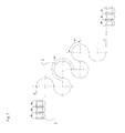
- FIG. 1 depicts a simplified schematic and perspective representation of a device or system for applying a multiple-pass print to containers in the form of bottles;
- FIG. 2 depicts the device of FIG. 1 in plan view
- FIG. 3 depicts a schematic representation and plan view of the transport or conveyor path of the bottles through the device shown in FIGS. 1 and 2 ;
- FIGS. 4-7 depict further embodiments of the invention in representations similar to FIG. 3 .
- the device generally designated by 1 in FIGS. 1 and 2 is used to apply a multiple-pass print to bottles 2 , either directly to the exterior or envelope surface of the bottles 2 , or to labels, e.g. provided with partial equipping, already affixed thereto.
- the bottles 2 are fed standing upright to the device 1 by means of an external conveyor in a transport direction A, then moved within the device 1 on a multiply arcuatedly deviated conveyor section. After printing, the bottles 2 are fed, still standing upright, by an external conveyor to a subsequent use.
- the transport path of the bottles 2 when feeding, when moving through the device 1 , and when exiting the device 1 , is represented schematically in FIG. 3 by the reference numeral 3 .
- the device 1 has a plurality of modules 4 . 1 - 4 . n arranged immediately contiguously in a transport direction A.
- the depicted embodiment has, in all, eight modules 4 . 1 - 4 . 8 , with all modules 4 . 1 - 4 . 8 being formed from an identical base unit 5 that is equipped with the functional elements necessary for the special task of the respective modules 4 . 1 - 4 . 8 .
- Each base unit 5 comprises, inter alia, a drive and control unit accommodated in a module housing 6 , and a transport element 7 having the form of a conveyor star or process star with a large number of holders 8 , the transport element 7 being arranged on the top of the module housing 6 and circumferentially drivable by the drive and control unit, inter alia, about a vertical machine axis of the respective modules 4 . 1 - 4 . 8 , the holders 8 being distributed at even angular distances over the periphery of the transport element 7 , each holder 8 serving to securely hold one bottle 2 .
- the transport elements 7 of the individual modules 4 . 1 - 4 . 8 are arranged immediately adjacent to one another and driven in counter-rotation but synchronously such that these transport elements 7 , in their totality, form a conveyor by which the bottles 2 are moved within the device 1 on the multiply deviated transport path 3 shown in FIG. 3 with the container intake at one end of the device 1 and the container outlet at the other end of the device 1 .
- the individual bottles 2 are each transferred directly from the transport element 7 of one module 4 . 1 - 4 . 7 to the transport element 7 of a successive module 4 . 2 - 4 . 8 that follows in the transport direction A.
- transport element 7 of module 4 . 1 which is the first relative to the transport direction A, is driven synchronously clockwise, transport element 7 of the next-following module 4 . 2 is driven counterclockwise, transport element of the next-following module 4 . 3 is again driven clockwise, and so forth.
- the synchronization of the individual modules 4 . 1 - 4 . 8 is effected by suitable control means.
- the individual modules 4 . 1 - 4 . 8 are also provided sequentially such that the vertical machine axes of all modules 4 . 1 - 4 . 8 lie in a common vertical plane parallel to which the feeding and discharge of the bottles 2 respectively to and from the device 1 is effected and in which are also located the transfer areas within which the bottles 2 are transferred from the transport element 7 of one module 4 . 1 - 4 . 7 to the transport element 7 of the module 4 . 2 - 4 . 8 that follows in transport direction A.
- the bottles 2 are each moved by the transport elements 7 of modules 4 . 1 and 4 . 8 over an angular range of approximately 90° about the vertical machine axis of modules 4 . 1 and 4 . 8 .
- the bottles 2 are each entrained by the transport element 7 concerned over an angular range of 180° about the vertical machine axis of the modules 4 . 2 - 4 . 7 .
- the process that is assigned to the respective module is effected within this angular range or within this path of the rotational motion of the transport element 7 concerned.
- this angular range can also be increased by appropriate arrangement of the contiguous modules, for example, to an angular range of 270°, as is suggested in FIG. 4 and FIG. 7 with the transport path 3 a at identified by reference numerals 9 and 10 shown therein.
- the transfer areas at which the bottle 2 is transferred to this module from a preceding module and to the subsequent module are offset by an angle greater than 180° about the machine axis, for example, by an angle of 270°, this being effected by the machine axis of the module with the increased angular range being arranged with the machine axis of the preceding module in a first vertical plane and with the machine axis of the subsequent module in a second vertical plane and by both planes including an angle, for example, an angle of 90°, to one another.
- the transport path over which the bottles 2 are moved through the device 1 can be configured at will by appropriate arrangement of the modules 4 . 1 - 4 . n according to the particular requirements and/or adapted to the particular spatial conditions, for example, as shown in FIG. 3 , such that the container intake and container outlet are located at opposite ends of the device 1 , as is the case with the version shown in FIGS. 1-3 , or alternatively according to FIG. 4 and/or according to the transport path 3 a therein shown such that the container intake and container outlet are located on a common side of the device or system, i.e. a head transport (HT) of the bottles 2 is effected through the system, or alternatively according to transport path 3 b in FIG.
- HT head transport
- An advantageous embodiment that is not shown includes the modules ( 4 . 1 - 4 . n ) having one or more printing heads and other functional elements arranged thereon.
- These other functional elements are, in particular, devices for the drying or intermediate drying of the printing ink.
- One or more devices for surface treatment and/or inspection may, however, also be provided alone or in combination therewith if need be.
Abstract
Description
-
- Module 4.1 forms, inter alia, the intake module and/or the container intake of the device 1. Module 4.1 also preferentially effects a pretreatment of the
bottles 2, at least in the bottle area that is to be printed, for example, a plasma or corona treatment, coating, adhesive application, electrostatic charge or the like, that is practicable particularly when the application of the multiple-pass print in the subsequent modules is effected with the use of printing stations or printing heads in those modules and that operate according to the known inkjet printing head principle or the so-called tone-jet principle. - The modules 4.2-4.5 following module 4.1 constitute the actual print modules in which the multiple-pass print is effected, preferentially as a color print in which one color set of the color print is printed at each of the modules 4.2-4.5, for example, in yellow, magenta, cyan and black.
- The module 4.6 that then follows in the transport direction A is configured as a drying module in which the previously generated multiple-pass print concerned is dried in a suitable manner, for example, by the application of energy in the form of, say, heat, microwaves, electron radiation and/or UV radiation.
- Module 4.7 is configured as an inspection module through which each
bottle 2 passes after the drying of the multiple-pass print, and in which the multiple-pass print concerned is examined for possible errors so that incorrectly printedbottles 2 can be separated out at module 4.7 or subsequently on the onward transport path. - Finally, module 4.8 constitutes the outlet module or container outlet of the device 1 at which the fully printed
bottles 2 exit the device 1. Module 4.8 is preferentially also configured as a drying module.
- Module 4.1 forms, inter alia, the intake module and/or the container intake of the device 1. Module 4.1 also preferentially effects a pretreatment of the
-
- 1 Device
- 2 Bottles or packaging containers
- 3, 3 a, 3 c Transport path
- 4.1-4.n Module
- 5 Base unit
- 6 Module housing
- 7 Transport element or transport or process star
- 8 Holder
- 9, 10 Section of the transport path
- A Direction of transport
Claims (20)
Applications Claiming Priority (4)
| Application Number | Priority Date | Filing Date | Title |
|---|---|---|---|
| DE102008049241A DE102008049241A1 (en) | 2008-09-26 | 2008-09-26 | Device for applying in each case a multiple printing on packaging |
| DE102008049241 | 2008-09-26 | ||
| DE102008049241.8 | 2008-09-26 | ||
| PCT/EP2009/005615 WO2010034375A1 (en) | 2008-09-26 | 2009-08-04 | Device for applying one multiple-pass print each to packaging containers |
Publications (2)
| Publication Number | Publication Date |
|---|---|
| US20110179959A1 US20110179959A1 (en) | 2011-07-28 |
| US8667895B2 true US8667895B2 (en) | 2014-03-11 |
Family
ID=41268162
Family Applications (1)
| Application Number | Title | Priority Date | Filing Date |
|---|---|---|---|
| US13/061,988 Expired - Fee Related US8667895B2 (en) | 2008-09-26 | 2009-08-04 | Device for applying one multiple-pass print each to packaging containers |
Country Status (9)
| Country | Link |
|---|---|
| US (1) | US8667895B2 (en) |
| EP (1) | EP2331338B1 (en) |
| JP (1) | JP5591244B2 (en) |
| CN (1) | CN102202902B (en) |
| BR (1) | BRPI0913727B1 (en) |
| DE (1) | DE102008049241A1 (en) |
| MX (1) | MX2011003153A (en) |
| RU (1) | RU2472626C2 (en) |
| WO (1) | WO2010034375A1 (en) |
Cited By (20)
| Publication number | Priority date | Publication date | Assignee | Title |
|---|---|---|---|---|
| US20140374016A1 (en) * | 2011-09-14 | 2014-12-25 | Khs Gmbh | Method and device for treating packaging means by applying decorations |
| US20150042706A1 (en) * | 2013-08-06 | 2015-02-12 | Machines Dubuit | Ink jet printing machine |
| US20150138295A1 (en) * | 2012-06-01 | 2015-05-21 | Krones Ag | Method and device for inspecting or correcting a direct print on containers with a relief-like surface contour |
| WO2016077199A1 (en) | 2014-11-13 | 2016-05-19 | The Procter & Gamble Company | Apparatus and method for depositing a substance on articles |
| WO2016077204A1 (en) | 2014-11-13 | 2016-05-19 | The Procter & Gamble Company | Digitally printed and decorated article |
| WO2016077203A1 (en) | 2014-11-13 | 2016-05-19 | The Procter & Gamble Company | Process for decorating an article |
| WO2016077201A1 (en) | 2014-11-13 | 2016-05-19 | The Procter & Gamble Company | Digitally printed article |
| WO2017040096A1 (en) | 2015-08-31 | 2017-03-09 | The Procter & Gamble Company | Parallel motion method for depositing a substance on articles |
| WO2017116668A2 (en) | 2015-12-28 | 2017-07-06 | The Procter & Gamble Company | Method and apparatus for applying a material onto articles using a continuous transfer component |
| WO2017116670A1 (en) | 2015-12-28 | 2017-07-06 | The Procter & Gamble Company | Method and apparatus for applying a material onto articles with a pre-distorted transfer component |
| WO2017116671A1 (en) | 2015-12-28 | 2017-07-06 | The Procter & Gamble Company | Method for transferring material with adhesive onto articles with a difference in degree of curing between the material and adhesive |
| WO2017116669A1 (en) | 2015-12-28 | 2017-07-06 | The Procter & Gamble Company | Method and apparatus for applying a material onto articles using a transfer component that deflects on both sides |
| US20180072072A1 (en) * | 2011-09-02 | 2018-03-15 | Khs Gmbh | Device for treating packages, and holding-and-centering unit for packages |
| WO2018227082A1 (en) | 2017-06-09 | 2018-12-13 | The Procter & Gamble Company | Method and compositions for applying a material onto articles |
| WO2018227084A1 (en) | 2017-06-09 | 2018-12-13 | The Procter & Gamble Company | Method for applying material onto and conforming to three-dimensional articles |
| WO2019099183A1 (en) | 2017-11-17 | 2019-05-23 | The Procter & Gamble Company | Methods for applying a material onto articles |
| EP3564042A2 (en) | 2018-05-01 | 2019-11-06 | The Procter & Gamble Company | Methods for applying a reflective material onto articles, and articles with reflective material thereon |
| EP3696109A1 (en) | 2019-02-12 | 2020-08-19 | The Procter & Gamble Company | Apparatus for applying a material onto articles using a transfer component |
| WO2021183350A1 (en) | 2020-03-09 | 2021-09-16 | The Procter & Gamble Company | Method and apparatus for applying a material onto articles using a transfer component |
| IT202100014864A1 (en) * | 2021-06-08 | 2022-12-08 | Quantix Digital S R L | PRE-TREATMENT DEVICE AND DIGITAL INKJET PRINTER INCLUDING SUCH PRE-TREATMENT DEVICE |
Families Citing this family (30)
| Publication number | Priority date | Publication date | Assignee | Title |
|---|---|---|---|---|
| ATE322975T1 (en) | 2001-09-19 | 2006-04-15 | Procter & Gamble | COLOR PRINTED MULTI-LAYER STRUCTURE, AN ABSORBENT ARTICLE MADE THEREFROM AND METHOD FOR PRODUCING THE SAME |
| DE102009058219A1 (en) * | 2009-12-15 | 2011-06-16 | Till, Volker, Dipl.-Ing. | Plant for printing on containers |
| EP3434490A1 (en) | 2010-07-23 | 2019-01-30 | Plastipak Packaging Inc. | Rotary system and method for printing containers |
| DE102010034780A1 (en) | 2010-08-18 | 2012-02-23 | Volker Till | Apparatus and method for printing on containers |
| DE102010036029A1 (en) * | 2010-08-31 | 2012-03-01 | Khs Gmbh | Process for treating preforms for the manufacture of containers by blow molding and for printing such containers |
| DE102010044244A1 (en) * | 2010-09-02 | 2012-03-08 | Khs Gmbh | Method and device for treating containers |
| DE102011007979A1 (en) | 2011-01-05 | 2012-07-05 | Till Gmbh | Machine for printing on containers |
| DE102011112106B3 (en) * | 2011-09-02 | 2013-02-21 | Khs Gmbh | Apparatus for performing multi-color printing on packaging structure e.g. bottle, has holding and centering unit which holds packaging structure, and specific unit of pressure segment supports and releases holding and centering unit |
| EP2750895B1 (en) * | 2011-09-02 | 2018-09-05 | KHS GmbH | Device for treating packaging means, and printing segment for use in a device of this type |
| DE102011119169A1 (en) | 2011-11-23 | 2013-05-23 | Khs Gmbh | Apparatus for applying equipment to containers |
| DE102011119171B3 (en) * | 2011-11-23 | 2013-02-21 | Khs Gmbh | Apparatus for treating containers with a suction device |
| US9239970B2 (en) | 2011-12-27 | 2016-01-19 | Showa Aluminum Can Corporation | Image forming system |
| JP6063231B2 (en) * | 2012-01-17 | 2017-01-18 | 昭和アルミニウム缶株式会社 | Image forming system |
| DE102012005926A1 (en) * | 2012-03-26 | 2013-09-26 | Khs Gmbh | Method and device for treating packaging |
| DE102012212882A1 (en) * | 2012-07-23 | 2014-01-23 | Krones Ag | Modular production plant and method for producing and / or filling containers |
| DE102012213079A1 (en) * | 2012-07-25 | 2014-01-30 | Krones Ag | System for printing containers, particularly plastic bottles filled with flowable medium with decorative or characterizing print motifs, has printing device and container pre-treatment device with four different pre-treatment units |
| JP6234023B2 (en) * | 2012-11-17 | 2017-11-22 | 株式会社ミマキエンジニアリング | Three-dimensional object printing system and three-dimensional object printing program |
| DE102013208061A1 (en) * | 2013-01-31 | 2013-07-04 | Krones Ag | Apparatus for printing e.g. content information on e.g. drink bottle, has UV lamp that is arranged on one of pressure plane to emit UV radiation for curing applied ink on containers |
| DE102013207799A1 (en) | 2013-04-29 | 2014-10-30 | Krones Ag | Direct printing method for printing on plastic containers with cover layer |
| DE102013215637A1 (en) * | 2013-08-08 | 2015-03-05 | Krones Ag | Flexible printing of containers |
| DE102013217202A1 (en) | 2013-08-28 | 2015-03-05 | Krones Ag | Device with dockable printing modules |
| DE102013110125A1 (en) * | 2013-09-13 | 2015-03-19 | Till Gmbh | Method and device for surface pretreatment of a three-dimensional body |
| DE102014103407A1 (en) | 2014-03-13 | 2015-09-17 | Khs Gmbh | Apparatus and method for drying printed containers |
| DE102014104645A1 (en) | 2014-04-02 | 2015-10-08 | Krones Aktiengesellschaft | Containers of articles provided with information applied by direct printing, articles joined together by an adhesive and process for the production thereof |
| CN107921791A (en) * | 2015-08-31 | 2018-04-17 | 宝洁公司 | For by electrodeposition substance in the parallel motion equipment on product |
| DE102015222996A1 (en) | 2015-11-20 | 2017-05-24 | Krones Ag | Curing station and method for curing ink of direct printing on containers |
| DE102016110316A1 (en) * | 2016-06-03 | 2017-12-07 | Khs Gmbh | Apparatus and method for printing on containers |
| US11174059B2 (en) | 2017-04-04 | 2021-11-16 | Sidel Participations | Decoration apparatus for decorating a web of labeling material and method of decorating a web of label material |
| DE102018111367A1 (en) * | 2018-05-14 | 2019-11-14 | Khs Gmbh | Apparatus and method for printing on containers |
| DE102022108149A1 (en) * | 2022-04-05 | 2023-10-05 | Krones Aktiengesellschaft | Method for printing on a container and device for printing on a container |
Citations (16)
| Publication number | Priority date | Publication date | Assignee | Title |
|---|---|---|---|---|
| DE4237577A1 (en) | 1991-11-10 | 1993-05-27 | A A A Software Consulting & Mf | Container re-filling code marking device - detects previously marked container code for positioning container relative to marking device to prevent codes overlapping |
| EP0813971A2 (en) | 1996-06-18 | 1997-12-29 | SCITEX DIGITAL PRINTING, Inc. | Modular electronic printer architecture |
| US5806420A (en) * | 1994-10-26 | 1998-09-15 | Metronic - Geratebau Gmbh & Co. | Printer for printing compact discs (CD) |
| US6019046A (en) * | 1995-04-10 | 2000-02-01 | Rodi; Anton | Printing press with replaceable units allowing for different methods of printing |
| US6298638B1 (en) | 1997-04-21 | 2001-10-09 | Graham Packaging Company, L.P. | System for blow-molding, filling and capping containers |
| US20020023559A1 (en) * | 2000-08-31 | 2002-02-28 | Eckart Frankenberger | Device for guiding sheets in a sheet processing apparatus |
| WO2004000936A1 (en) | 2002-06-21 | 2003-12-31 | General Electric Company | Impact-modified compositions |
| DE10322556A1 (en) | 2002-09-27 | 2004-04-08 | Robert Bosch Gmbh | Device for handling containers for filling and closing has conveyor unit moving containers along past stations which have frame units of structurally identical size and connectable together whilst function devices have independent drives |
| US20050120901A1 (en) * | 2003-12-09 | 2005-06-09 | Heidelberger Druckmaschinen Ag | Modular sheet-fed rotary printing press |
| EP1625942A2 (en) | 2004-08-13 | 2006-02-15 | Xerox Corporation | Parallel printing architecture with modular image recording apparatuses and media feeder modules |
| US20060144261A1 (en) | 2004-12-30 | 2006-07-06 | Plastipak Packaging, Inc. | Printing plastic containers with digital images |
| US20060250464A1 (en) | 2003-09-17 | 2006-11-09 | Yehoshua Sheinman | Method and apparatus for printing selected information on bottles |
| EP2152519A1 (en) | 2007-08-03 | 2010-02-17 | Khs Ag | Device and method for printing containers |
| US20110067584A1 (en) * | 2008-03-11 | 2011-03-24 | Polytype S.A. | Modular linear printing press for printing hollow articles by means of different printing processes |
| US20120199021A1 (en) * | 2009-07-18 | 2012-08-09 | Khs Gmbh | Equipment for printing on containers |
| US20120255450A1 (en) * | 2009-12-15 | 2012-10-11 | Heinz Till | Plant for printing containers |
Family Cites Families (4)
| Publication number | Priority date | Publication date | Assignee | Title |
|---|---|---|---|---|
| JP2000218214A (en) * | 1998-11-25 | 2000-08-08 | Surf Coat:Kk | Printing or coating method for vessel and printing or coating device |
| WO2004009360A1 (en) * | 2002-07-22 | 2004-01-29 | Sealed Air Limited | Printing process and apparatus |
| US6920822B2 (en) * | 2003-09-03 | 2005-07-26 | Stolle Machinery Company, Llc | Digital can decorating apparatus |
| US8555311B2 (en) | 2007-12-19 | 2013-10-08 | United Video Properties, Inc. | Methods and devices for presenting guide listings and guidance data in three dimensions in an interactive media guidance application |
-
2008
- 2008-09-26 DE DE102008049241A patent/DE102008049241A1/en not_active Withdrawn
-
2009
- 2009-08-04 WO PCT/EP2009/005615 patent/WO2010034375A1/en active Application Filing
- 2009-08-04 US US13/061,988 patent/US8667895B2/en not_active Expired - Fee Related
- 2009-08-04 BR BRPI0913727-0A patent/BRPI0913727B1/en not_active IP Right Cessation
- 2009-08-04 CN CN200980137982.6A patent/CN102202902B/en not_active Expired - Fee Related
- 2009-08-04 RU RU2011116311/12A patent/RU2472626C2/en active
- 2009-08-04 EP EP09777621.5A patent/EP2331338B1/en not_active Not-in-force
- 2009-08-04 MX MX2011003153A patent/MX2011003153A/en active IP Right Grant
- 2009-08-04 JP JP2011528198A patent/JP5591244B2/en not_active Expired - Fee Related
Patent Citations (16)
| Publication number | Priority date | Publication date | Assignee | Title |
|---|---|---|---|---|
| DE4237577A1 (en) | 1991-11-10 | 1993-05-27 | A A A Software Consulting & Mf | Container re-filling code marking device - detects previously marked container code for positioning container relative to marking device to prevent codes overlapping |
| US5806420A (en) * | 1994-10-26 | 1998-09-15 | Metronic - Geratebau Gmbh & Co. | Printer for printing compact discs (CD) |
| US6019046A (en) * | 1995-04-10 | 2000-02-01 | Rodi; Anton | Printing press with replaceable units allowing for different methods of printing |
| EP0813971A2 (en) | 1996-06-18 | 1997-12-29 | SCITEX DIGITAL PRINTING, Inc. | Modular electronic printer architecture |
| US6298638B1 (en) | 1997-04-21 | 2001-10-09 | Graham Packaging Company, L.P. | System for blow-molding, filling and capping containers |
| US20020023559A1 (en) * | 2000-08-31 | 2002-02-28 | Eckart Frankenberger | Device for guiding sheets in a sheet processing apparatus |
| WO2004000936A1 (en) | 2002-06-21 | 2003-12-31 | General Electric Company | Impact-modified compositions |
| DE10322556A1 (en) | 2002-09-27 | 2004-04-08 | Robert Bosch Gmbh | Device for handling containers for filling and closing has conveyor unit moving containers along past stations which have frame units of structurally identical size and connectable together whilst function devices have independent drives |
| US20060250464A1 (en) | 2003-09-17 | 2006-11-09 | Yehoshua Sheinman | Method and apparatus for printing selected information on bottles |
| US20050120901A1 (en) * | 2003-12-09 | 2005-06-09 | Heidelberger Druckmaschinen Ag | Modular sheet-fed rotary printing press |
| EP1625942A2 (en) | 2004-08-13 | 2006-02-15 | Xerox Corporation | Parallel printing architecture with modular image recording apparatuses and media feeder modules |
| US20060144261A1 (en) | 2004-12-30 | 2006-07-06 | Plastipak Packaging, Inc. | Printing plastic containers with digital images |
| EP2152519A1 (en) | 2007-08-03 | 2010-02-17 | Khs Ag | Device and method for printing containers |
| US20110067584A1 (en) * | 2008-03-11 | 2011-03-24 | Polytype S.A. | Modular linear printing press for printing hollow articles by means of different printing processes |
| US20120199021A1 (en) * | 2009-07-18 | 2012-08-09 | Khs Gmbh | Equipment for printing on containers |
| US20120255450A1 (en) * | 2009-12-15 | 2012-10-11 | Heinz Till | Plant for printing containers |
Cited By (40)
| Publication number | Priority date | Publication date | Assignee | Title |
|---|---|---|---|---|
| US20180072072A1 (en) * | 2011-09-02 | 2018-03-15 | Khs Gmbh | Device for treating packages, and holding-and-centering unit for packages |
| US9457926B2 (en) * | 2011-09-14 | 2016-10-04 | Khs Gmbh | Method and device for treating packaging means by applying decorations |
| US20140374016A1 (en) * | 2011-09-14 | 2014-12-25 | Khs Gmbh | Method and device for treating packaging means by applying decorations |
| US20150138295A1 (en) * | 2012-06-01 | 2015-05-21 | Krones Ag | Method and device for inspecting or correcting a direct print on containers with a relief-like surface contour |
| US9649856B2 (en) * | 2012-06-01 | 2017-05-16 | Krones Ag | Method and device for inspecting or correcting a direct print on containers with a relief-like surface contour |
| US20150042706A1 (en) * | 2013-08-06 | 2015-02-12 | Machines Dubuit | Ink jet printing machine |
| US9527305B2 (en) * | 2013-08-06 | 2016-12-27 | Machines Dubuit | Ink jet printing machine |
| CN107107627B (en) * | 2014-11-13 | 2018-10-02 | 宝洁公司 | For by the device and method on electrodeposition substance to product |
| WO2016077199A1 (en) | 2014-11-13 | 2016-05-19 | The Procter & Gamble Company | Apparatus and method for depositing a substance on articles |
| US10252544B2 (en) | 2014-11-13 | 2019-04-09 | The Procter & Gamble Company | Apparatus and method for depositing a substance on articles |
| WO2016077203A1 (en) | 2014-11-13 | 2016-05-19 | The Procter & Gamble Company | Process for decorating an article |
| WO2016077201A1 (en) | 2014-11-13 | 2016-05-19 | The Procter & Gamble Company | Digitally printed article |
| WO2016077204A1 (en) | 2014-11-13 | 2016-05-19 | The Procter & Gamble Company | Digitally printed and decorated article |
| CN107107627A (en) * | 2014-11-13 | 2017-08-29 | 宝洁公司 | For by the apparatus and method on electrodeposition substance to product |
| WO2017040096A1 (en) | 2015-08-31 | 2017-03-09 | The Procter & Gamble Company | Parallel motion method for depositing a substance on articles |
| WO2017116671A1 (en) | 2015-12-28 | 2017-07-06 | The Procter & Gamble Company | Method for transferring material with adhesive onto articles with a difference in degree of curing between the material and adhesive |
| WO2017116669A1 (en) | 2015-12-28 | 2017-07-06 | The Procter & Gamble Company | Method and apparatus for applying a material onto articles using a transfer component that deflects on both sides |
| WO2017116672A1 (en) | 2015-12-28 | 2017-07-06 | The Procter & Gamble Company | Three-dimensional article having transfer material thereon |
| WO2017116670A1 (en) | 2015-12-28 | 2017-07-06 | The Procter & Gamble Company | Method and apparatus for applying a material onto articles with a pre-distorted transfer component |
| US10486368B2 (en) | 2015-12-28 | 2019-11-26 | The Procter & Gamble Company | Method for transferring material with adhesive onto articles with a difference in degree of curing between the material and adhesive |
| US11141995B2 (en) | 2015-12-28 | 2021-10-12 | The Procter & Gamble Company | Method and apparatus for applying a material onto articles with a pre-distorted transfer component |
| WO2017116668A2 (en) | 2015-12-28 | 2017-07-06 | The Procter & Gamble Company | Method and apparatus for applying a material onto articles using a continuous transfer component |
| US10940685B2 (en) | 2015-12-28 | 2021-03-09 | The Procter & Gamble Company | Method and apparatus for applying a material onto articles using a transfer component that deflects on both sides |
| US10668667B2 (en) | 2015-12-28 | 2020-06-02 | The Procter & Gamble Company | Method for transferring material with adhesive onto articles with a difference in degree of curing between the material and adhesive |
| WO2018227084A1 (en) | 2017-06-09 | 2018-12-13 | The Procter & Gamble Company | Method for applying material onto and conforming to three-dimensional articles |
| US10682837B2 (en) | 2017-06-09 | 2020-06-16 | The Proctor & Gamble Company | Method and compositions for applying a material onto articles |
| WO2018227082A1 (en) | 2017-06-09 | 2018-12-13 | The Procter & Gamble Company | Method and compositions for applying a material onto articles |
| WO2019099183A1 (en) | 2017-11-17 | 2019-05-23 | The Procter & Gamble Company | Methods for applying a material onto articles |
| US10752795B2 (en) | 2017-11-17 | 2020-08-25 | The Procter & Gamble Company | Compositions and methods for applying a material onto articles |
| EP3564042A2 (en) | 2018-05-01 | 2019-11-06 | The Procter & Gamble Company | Methods for applying a reflective material onto articles, and articles with reflective material thereon |
| EP3696108A1 (en) | 2019-02-12 | 2020-08-19 | The Procter & Gamble Company | Method for applying a material onto articles using a transfer component |
| EP3696110A1 (en) | 2019-02-12 | 2020-08-19 | The Procter & Gamble Company | Apparatus for applying a material onto articles using a transfer component |
| EP3696107A1 (en) | 2019-02-12 | 2020-08-19 | The Procter & Gamble Company | Method for applying a material onto articles using a transfer component |
| EP3696106A1 (en) | 2019-02-12 | 2020-08-19 | The Procter & Gamble Company | Method for applying a material onto articles using a transfer component |
| EP3696109A1 (en) | 2019-02-12 | 2020-08-19 | The Procter & Gamble Company | Apparatus for applying a material onto articles using a transfer component |
| US11491803B2 (en) | 2019-02-12 | 2022-11-08 | The Procter & Gamble Company | Method and apparatus for applying a material onto articles using a transfer component |
| WO2021183350A1 (en) | 2020-03-09 | 2021-09-16 | The Procter & Gamble Company | Method and apparatus for applying a material onto articles using a transfer component |
| US11752792B2 (en) | 2020-03-09 | 2023-09-12 | The Procter & Gamble Company | Method and apparatus for applying a material onto articles using a transfer component |
| IT202100014864A1 (en) * | 2021-06-08 | 2022-12-08 | Quantix Digital S R L | PRE-TREATMENT DEVICE AND DIGITAL INKJET PRINTER INCLUDING SUCH PRE-TREATMENT DEVICE |
| WO2022258396A1 (en) * | 2021-06-08 | 2022-12-15 | Quantix Digital S.R.L. | Pretreatment device and ink jet digital printing machine including said pretreatment device |
Also Published As
| Publication number | Publication date |
|---|---|
| CN102202902A (en) | 2011-09-28 |
| WO2010034375A1 (en) | 2010-04-01 |
| EP2331338A1 (en) | 2011-06-15 |
| BRPI0913727A2 (en) | 2015-10-13 |
| JP2012503576A (en) | 2012-02-09 |
| US20110179959A1 (en) | 2011-07-28 |
| RU2011116311A (en) | 2012-11-10 |
| BRPI0913727B1 (en) | 2019-03-06 |
| JP5591244B2 (en) | 2014-09-17 |
| EP2331338B1 (en) | 2014-07-23 |
| DE102008049241A1 (en) | 2010-04-08 |
| MX2011003153A (en) | 2011-04-27 |
| CN102202902B (en) | 2014-07-16 |
| RU2472626C2 (en) | 2013-01-20 |
Similar Documents
| Publication | Publication Date | Title |
|---|---|---|
| US8667895B2 (en) | Device for applying one multiple-pass print each to packaging containers | |
| US9132664B2 (en) | Device and method for adding information on the outer surface of articles, such as containers in a container filling plant | |
| EP2703305B1 (en) | Ink-jet printer and method for printing seamless can using same | |
| US7997201B2 (en) | Method and device for labeling containers | |
| JP6599571B2 (en) | Mechanical structure including a printing apparatus for continuously processing a sheet-like base material | |
| US20180072072A1 (en) | Device for treating packages, and holding-and-centering unit for packages | |
| US20070157576A1 (en) | Beverage bottling plant for filling beverage bottles with a liquid beverage, with an information adding arrangement for adding information relating to the beverage bottles, and a method of operating the beverage bottling plant | |
| US10252544B2 (en) | Apparatus and method for depositing a substance on articles | |
| CN102615956A (en) | Method and device for printing containers | |
| US10538355B2 (en) | Device for treating packages, and pressure segment for use in a device of this type | |
| EP3218201B1 (en) | Digitally printed article | |
| JP2010511529A (en) | Inkjet printing apparatus and method | |
| US20170056918A1 (en) | Parallel Motion Method for Depositing a Substance on Articles | |
| US20170056900A1 (en) | Parallel Motion Apparatus for Depositing a Substance on Articles | |
| CN108136779A (en) | Print assembly and at least one absorption box to be arranged into the method in printing assembly |
Legal Events
| Date | Code | Title | Description |
|---|---|---|---|
| AS | Assignment |
Owner name: KHS GMBH, GERMANY Free format text: ASSIGNMENT OF ASSIGNORS INTEREST;ASSIGNORS:GERIGK, KATRIN;PSCHICHHOLZ, MANFRED;PUTZER, FRANK;AND OTHERS;SIGNING DATES FROM 20110304 TO 20110322;REEL/FRAME:026036/0743 |
|
| FEPP | Fee payment procedure |
Free format text: PAYOR NUMBER ASSIGNED (ORIGINAL EVENT CODE: ASPN); ENTITY STATUS OF PATENT OWNER: LARGE ENTITY |
|
| STCF | Information on status: patent grant |
Free format text: PATENTED CASE |
|
| MAFP | Maintenance fee payment |
Free format text: PAYMENT OF MAINTENANCE FEE, 4TH YEAR, LARGE ENTITY (ORIGINAL EVENT CODE: M1551) Year of fee payment: 4 |
|
| FEPP | Fee payment procedure |
Free format text: MAINTENANCE FEE REMINDER MAILED (ORIGINAL EVENT CODE: REM.); ENTITY STATUS OF PATENT OWNER: LARGE ENTITY |
|
| LAPS | Lapse for failure to pay maintenance fees |
Free format text: PATENT EXPIRED FOR FAILURE TO PAY MAINTENANCE FEES (ORIGINAL EVENT CODE: EXP.); ENTITY STATUS OF PATENT OWNER: LARGE ENTITY |
|
| STCH | Information on status: patent discontinuation |
Free format text: PATENT EXPIRED DUE TO NONPAYMENT OF MAINTENANCE FEES UNDER 37 CFR 1.362 |
|
| FP | Lapsed due to failure to pay maintenance fee |
Effective date: 20220311 |