US8684281B2 - Spray device having removable hard coated tip - Google Patents
Spray device having removable hard coated tip Download PDFInfo
- Publication number
- US8684281B2 US8684281B2 US11/389,450 US38945006A US8684281B2 US 8684281 B2 US8684281 B2 US 8684281B2 US 38945006 A US38945006 A US 38945006A US 8684281 B2 US8684281 B2 US 8684281B2
- Authority
- US
- United States
- Prior art keywords
- spray
- liquid
- passage
- wear resistant
- resistant coating
- Prior art date
- Legal status (The legal status is an assumption and is not a legal conclusion. Google has not performed a legal analysis and makes no representation as to the accuracy of the status listed.)
- Active, expires
Links
Images


Classifications
-
- B—PERFORMING OPERATIONS; TRANSPORTING
- B05—SPRAYING OR ATOMISING IN GENERAL; APPLYING FLUENT MATERIALS TO SURFACES, IN GENERAL
- B05B—SPRAYING APPARATUS; ATOMISING APPARATUS; NOZZLES
- B05B15/00—Details of spraying plant or spraying apparatus not otherwise provided for; Accessories
- B05B15/14—Arrangements for preventing or controlling structural damage to spraying apparatus or its outlets, e.g. for breaking at desired places; Arrangements for handling or replacing damaged parts
- B05B15/18—Arrangements for preventing or controlling structural damage to spraying apparatus or its outlets, e.g. for breaking at desired places; Arrangements for handling or replacing damaged parts for improving resistance to wear, e.g. inserts or coatings; for indicating wear; for handling or replacing worn parts
-
- B—PERFORMING OPERATIONS; TRANSPORTING
- B05—SPRAYING OR ATOMISING IN GENERAL; APPLYING FLUENT MATERIALS TO SURFACES, IN GENERAL
- B05B—SPRAYING APPARATUS; ATOMISING APPARATUS; NOZZLES
- B05B1/00—Nozzles, spray heads or other outlets, with or without auxiliary devices such as valves, heating means
-
- B—PERFORMING OPERATIONS; TRANSPORTING
- B05—SPRAYING OR ATOMISING IN GENERAL; APPLYING FLUENT MATERIALS TO SURFACES, IN GENERAL
- B05B—SPRAYING APPARATUS; ATOMISING APPARATUS; NOZZLES
- B05B7/00—Spraying apparatus for discharge of liquids or other fluent materials from two or more sources, e.g. of liquid and air, of powder and gas
- B05B7/02—Spray pistols; Apparatus for discharge
- B05B7/08—Spray pistols; Apparatus for discharge with separate outlet orifices, e.g. to form parallel jets, i.e. the axis of the jets being parallel, to form intersecting jets, i.e. the axis of the jets converging but not necessarily intersecting at a point
- B05B7/0807—Spray pistols; Apparatus for discharge with separate outlet orifices, e.g. to form parallel jets, i.e. the axis of the jets being parallel, to form intersecting jets, i.e. the axis of the jets converging but not necessarily intersecting at a point to form intersecting jets
- B05B7/0815—Spray pistols; Apparatus for discharge with separate outlet orifices, e.g. to form parallel jets, i.e. the axis of the jets being parallel, to form intersecting jets, i.e. the axis of the jets converging but not necessarily intersecting at a point to form intersecting jets with at least one gas jet intersecting a jet constituted by a liquid or a mixture containing a liquid for controlling the shape of the latter
-
- Y—GENERAL TAGGING OF NEW TECHNOLOGICAL DEVELOPMENTS; GENERAL TAGGING OF CROSS-SECTIONAL TECHNOLOGIES SPANNING OVER SEVERAL SECTIONS OF THE IPC; TECHNICAL SUBJECTS COVERED BY FORMER USPC CROSS-REFERENCE ART COLLECTIONS [XRACs] AND DIGESTS
- Y10—TECHNICAL SUBJECTS COVERED BY FORMER USPC
- Y10T—TECHNICAL SUBJECTS COVERED BY FORMER US CLASSIFICATION
- Y10T29/00—Metal working
- Y10T29/49—Method of mechanical manufacture
- Y10T29/49428—Gas and water specific plumbing component making
- Y10T29/49432—Nozzle making
- Y10T29/49433—Sprayer
Definitions
- the invention relates generally to spray devices and, more particularly, to spray tips of spray guns used in spray coating systems.
- Spray devices such as spray guns, generally include a number of consumable wear items, which eventually erode due to contact with liquid passing through passages and orifices of the spray device.
- the liquid exit orifice in spray tips of spray coating guns eventually erodes from contact with the liquid paint at high pressures.
- the spray tips are typically cast from tungsten carbide to provide wear resistance.
- tungsten carbide is relatively expensive and is difficult to cast and machine into the desired geometry, passages, orifices, and so forth.
- the process of casting the tungsten carbide into the initial form of the spray tips results in relatively large internal bores for the subsequent machining and processing.
- these large internal bores define a large volume, which tends to retain the liquid paint within the spray tip after operation of the spray coating gun. This retention of paint within the spray tip causes the spray coating gun to drip or dribble after operation.
- the hardness of tungsten carbide complicates the process of making the liquid exit orifice in the spray tips.
- the hardness of tungsten carbide generally precludes the use of some manufacturing techniques, while making it difficult to achieve the desired shape with other manufacturing techniques.
- the hardness of tungsten carbide rapidly wears many manufacturing tools, such as grinding wheels, thereby increasing costs and time associated with replacing the worn tools.
- the desired shape of the liquid exit orifice cannot be achieved with tungsten carbide, which can lead to reduced performance and undesirable spray characteristics from the spray tip.
- a spray system is provided with a spray tip including a core tip structure having a first material, wherein the core tip structure includes a liquid passage extending to a liquid exit orifice.
- the spray tip also includes a wear resistant coating disposed about the core tip structure, wherein the wear resistant coating has a second material relatively harder than the first material.
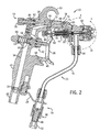
- FIG. 1 is a perspective view of an exemplary spray device having a hard coated spray tip in accordance with certain embodiments of the present technique
- FIG. 2 is a cross-sectional side view of the spray device as illustrated in FIG. 2 , further illustrating internal components and passages leading to the hard coated spray tip;
- FIG. 3 is a partial cross-sectional view of the spray device as illustrated in FIGS. 1 and 2 , further illustrating details of the hard coated spray tip;
- FIG. 4 is a cross-sectional side view of an alternative hard coated spray tip having a truncated end and a streamlined interior passage in accordance with certain embodiments of the present technique
- FIG. 5 is a perspective view of the alternative hard coated spray tip as illustrated in FIG. 4 ;
- FIG. 6 is a top view of the hard coated spray tip as illustrated in FIGS. 4 and 5 .
- FIG. 1 is a perspective view of an exemplary spray device 10 having a hard coated spray tip 12 disposed within a head assembly 14 in accordance with certain embodiments of the present technique.
- the spray device 10 is an airless spray coating gun or an air-assisted spray coating gun, which generally atomize the liquid without air atomization mechanisms.
- an air-assisted spray coating gun may include air jets configured to shape the liquid spray in the desired pattern, e.g., flat, conical, hollow, and so forth.
- the spray device 10 may be an air atomization spray gun, which includes one or more air jets configured to atomize the liquid.
- the air atomization spray gun also may include one or more spray shaping jets as mentioned above.
- the hard coated spray tip 12 includes a core tip structure made of a first material and a coating of a second material disposed about the core tip structure, wherein the second material is relatively harder than the first material.
- the relatively softer first material of the core tip structure reduces time, costs, and complexities associated with casting, machining, and other manufacturing processes.
- the softer first material is more easily and effectively made into the desired internal and external dimensions, shapes, recesses, orifices, passages, and general geometry of the core tip structure.
- EDM wire electrical discharge machining
- the core tip structure is hardened with the coating of the second material.
- the coating of the second material may be applied with chemical vapor deposition (CVD), physical vapor deposition (PVD), or plating, or thermal diffusion, or boronizing, or combinations thereof.
- the head assembly 14 is coupled to a body assembly 18 of the spray device 10 .
- the illustrated body assembly 18 includes a handle 20 and an air supply coupling 22 disposed at a base 24 of the handle 20 .
- the body assembly 18 also includes a liquid supply assembly 26 coupled to the base 24 of the handle 20 via a bracket 28 .
- the liquid supply assembly 26 is further coupled to the head assembly 14 via a liquid head coupling 30 .
- the illustrated liquid supply assembly 26 includes a liquid supply coupling 32 , a liquid filter assembly 34 , and a liquid conduit 36 leading to the liquid head coupling 30 .
- the body assembly 18 also includes a trigger 38 rotatably coupled to a pivot joint 40 .
- the trigger 38 is movably coupled to an air valve assembly 42 and a liquid valve assembly 44 , such that the trigger simultaneously controls the passage of air and liquid through the spray device 10 .
- the body assembly 18 includes a trigger lock 46 rotatably coupled to a pivot joint 48 in close proximity to the trigger 38 .
- the trigger lock 46 enables a user to lock or unlock the trigger 38 and, as a result, the associated air and liquid valve assemblies 42 and 44 .
- the illustrated body assembly 18 also includes a hanging support or hook 50 disposed along a top 52 of the spray device 10 .
- the spray device 10 may further include air and liquid conduits leading to the air and liquid supply couplings 22 and 32 .
- a plurality of the spray devices 10 may be coupled to one or more positioning systems, control units, user interfaces, computers, and so forth.
- an exemplary positioning system may include one or more robotic arms, overhead rail structures having moving supports, or combinations thereof.
- the spray guns 10 may be coordinated with one another to perform a desired spraying operation, such as spraying a plurality of automobiles in an assembly line.
- the spraying system also may include associated systems and devices, such as infrared heaters or other curing devices configured to cure a spray coating.
- FIG. 2 is a cross-sectional view of the spray device 10 as illustrated in FIG. 1 , further illustrating internal components and flow passages through the head and body assemblies 14 and 18 in accordance with certain embodiments of the present technique.
- the body assembly 18 includes a series of air passages 54 , 56 , 58 , and 60 leading from the air supply coupling 22 to an air nozzle assembly 62 of the head assembly 14 .
- the air valve assembly 42 is disposed between the air passages 54 and 56 to control the passage of air via operation of the trigger 38 .
- the air valve assembly 42 includes a spring 64 disposed adjacent a moveable valve member 66 , which move linearly along a valve channel 68 as the trigger 38 rotates about the pivot joint 40 .
- a pressure or flow control assembly 70 Downstream from the air valve assembly 42 , a pressure or flow control assembly 70 is disposed along the air passage 58 .
- the pressure or flow control assembly 70 includes an adjustment valve 72 having a wedge-shaped valve tip 74 disposed near a wedged portion 76 of the air passage 58 .
- the pressure or flow control assembly 70 also includes an adjustment head 78 coupled to the adjustment valve 72 and rotatably coupled to the body assembly 18 via threads 80 . Accordingly, the adjustment head 78 may be rotated to change the linear distance or proximity of the wedge-shaped valve tip 74 relative to the wedged portion 76 of the air passage 58 . In this manner, the pressure or flow control assembly 78 can adjust the rate or pressure of air flow to the air nozzle assembly 62 .
- the trigger 38 rotates about the pivot joint 40 to open and close the liquid valve assembly 44 , which extends through the head assembly 14 to the hard coated spray tip 12 .
- the liquid valve assembly 44 includes a valve shaft 82 coupled to the trigger 38 via a fastener 84 .
- the liquid valve assembly 44 also includes a needle packing cartridge assembly 86 disposed about the valve shaft 82 and threadingly coupled to the head assembly 14 .
- the illustrated needle packing cartridge assembly 86 includes a cylindrical casing 88 and an internal coil spring 90 disposed about the valve shaft 82 .
- the needle packing cartridge assembly 86 also includes one or more seals, such as o-ring seals 92 and 94 .
- the valve shaft 82 In operation, as the trigger 38 rotates clockwise about the pivot joint 40 , the valve shaft 82 is biased linearly to the left to an open position that enables the passage of liquid from the liquid supply assembly 26 to the hard coated spray tip 12 .
- the liquid supply assembly 26 includes a liquid filter assembly 34 .
- the liquid filter assembly 34 includes a filter 96 , such as a mesh filter cartridge, disposed within a filter housing 98 between the liquid supply coupling 32 and the liquid conduit 36 .
- a variety of filter mechanisms may be disposed inside the filter housing 98 .
- the hard coated spray tip 12 provides resistance against erosion by the liquid, e.g., paint or another liquid coating material.
- the liquid may include particulate matter, such that a two-phase flow of liquid and solid passes through the spray device 10 and the hard coated spray tip 12 .
- particulate paint may be described as particulate paint, which includes both liquid and solid particles.
- the filter 96 is configured to remove larger particles from the liquid, while the hard coating of the spray tip 12 provides resistance against wear by the passing liquid (and any remaining particles).
- FIG. 3 is a partial cross-sectional view of the spray device 10 as illustrated in FIGS. 1 and 2 , further illustrating details of the head assembly 14 in accordance with certain embodiments of the present technique.
- the air nozzle assembly 62 includes a first annular member 110 threadingly coupled to a central liquid passage 111 via threads 112 .
- the air nozzle assembly 62 also includes a second annular member 113 disposed concentrically about the first annular member 110 and sealed against the body assembly 18 via an o-ring 114 .
- the air nozzle assembly 62 further includes a third annular member 115 disposed concentrically about the second annular member 113 , and an air-assisted spray shaping head assembly 116 disposed adjacent the third annular member 115 .
- the air-assisted spray shaping head assembly 116 includes one or more fourth annular members, e.g., two concentric members 117 and 118 .
- the air nozzle assembly 62 also may include one or more adapters, bushings, washers, or other structures between the head assembly 116 and the hard coated spray tip 12 .
- the illustrated embodiment includes an outer holder 119 disposed about the hard coated spray tip 12 , an inner bushing or adapter 120 disposed at least partially into the hard coated spray tip 12 , and a rear washer 121 disposed against a rear side of the adapter 120 flush with a rear side of the outer holder 119 .
- the air nozzle assembly 62 includes an outer casing or retainer 122 disposed about the members 110 , 113 , 115 , 116 , 119 , 120 , and 121 and threadingly coupled to the body assembly 18 via threads 124 .
- the illustrated members 110 , 113 , 115 , 116 , 119 , 120 , 121 , and 122 define or include a plurality of air passages 126 , 128 , 130 , 132 , and 134 leading from the air passage 60 in the body assembly 18 to one or more air jets 136 disposed in the air-assisted spray shaping head 116 .
- a plurality of these air jets 136 are angled toward a center line or center plane 138 of the hard coated spray tip 12 .
- the air jets 136 provide air flow or pressure to shape the liquid spray that develops downstream of the cat-eye orifice 16 .
- the air jets 136 may be configured to shape the spray in a generally flat or sheet-like pattern.
- the illustrated embodiment does not include air atomization jets, but rather the spray is formed substantially by liquid atomization from the cat-eye orifice 16 of the hard coated spray tip 12 .
- the spray device 10 may include one or more air atomization jets to cooperate with the hard coated spray tip 12 , thereby creating a desired spray via both liquid atomization and air atomization.
- valve shaft 82 moves linearly along the axis 136 to open and close a ball valve member 140 as indicated by arrow 142 .
- the ball valve member 140 is disposed between an end 144 of the valve shaft 82 and a wedge-shaped cavity or passage 146 within the first annular member 110 of the air nozzle assembly 62 . Accordingly, the flow of liquid through the head assembly 14 to the hard coated spray tip 12 is controlled by biasing or releasing the ball valve member 140 relative to the wedge-shaped cavity or passage 146 .
- the end 144 of the valve shaft 82 may have a wedge-shaped tip (e.g., a needle valve), which can be removably biased against the wedge-shaped cavity or passage 146 to open and close the flow of liquid through the head assembly 14 .
- a wedge-shaped tip e.g., a needle valve
- the hard coated spray tip 12 includes a core tip structure 148 made of a first material and a hard coating 150 of a second material disposed about the core tip structure 148 , wherein the second material is relatively harder than the first material.
- the first material of the core tip structure 148 may include one or more tool steels, or another material, or combinations thereof. More specifically, exemplary tool steels include a type A tool steel, or a type D tool steel, or a type H tool steel, or a type M tool steel, or a type S tool steel, or combinations thereof.
- the second material of the hard coating 150 may include chrome, titanium alloys, or other relatively harder materials than the first material, or combinations thereof.
- the hard coating 150 may include a plurality of layers of hard materials.
- the hard coating 150 may include a first coating layer, a second coating layer, a third coating layer, and so forth. These coating layers may have different material compositions and properties.
- one or more of the layers may provide resistance to wear, while others may provide resistance to chemical attack of the underlying first material of the core tip structure 148 .
- One exemplary arrangement of hard coating layers includes one or more inner chemically resistant layers covered by one or more outer wear resistant layers.
- the first material includes a D2 tool steel and the second material includes titanium nitride.
- An exemplary D2 tool steel may include about 1.4 to 1.6% carbon, about 0 to 0.6% manganese, about 0 to 0.6% silicon, about 11-13% chromium, about 0 to 0.3% nickel, about 0.7 to 1.2% molybdenum, and about 0 to 1.1% vanadium.
- the relatively softer nature of the first material enables ease of manufacturing of the core tip structure 148 followed by hardening via the second material of the hard coating 150 .
- certain embodiments of the core tip structure 148 are manufactured by molding, casting, machining, drilling, grinding, wire electrical discharge machining (EDM), or combinations thereof.
- the hard coating 150 may be applied via plating, or thermal diffusion, or boronizing, or chemical vapor deposition (CVD), or physical vapor deposition (PVD), or combinations thereof.
- the core tip structure 148 is fabricated from a tool steel (e.g., D2 tool steel) and the cat-eye orifice is created by wire electrical discharge machining (EDM), while the hard coating 150 is applied by chemical vapor deposition (CVD) of titanium oxide.
- a tool steel e.g., D2 tool steel
- EDM wire electrical discharge machining
- CVD chemical vapor deposition
- the internal geometry of the illustrated core tip structure 148 has a first cylindrical passage 152 , a converging passage 154 , and a second cylindrical passage 156 leading to the cat-eye orifice 16 .
- the external geometry of the illustrated core tip structure 148 includes a first cylindrical portion 158 , a step portion 160 leading to a second cylindrical portion 162 , and a semi-spherical or convex face 164 .
- the internal and external geometries of the core tip structure 148 may be adapted to any particular spray device 10 .
- the internal and external geometries may be modified to reduce cost, improve the spray performance, and reduce liquid retention.
- the hard coated spray tip 12 and one or more sets of the members 110 , 113 , 115 , 116 , 119 , 120 , and 121 , or combinations thereof may be integrally formed as a single piece or structure, wherein the single piece or structure has a solid core and an external hard coating.
- the solid core may be similar to the core tip structure 148 and the hard coating may be similar to the hard coating 150 as described in detail above.
- the integration of parts into a single piece or structure decreases the number of parts, complexity, and costs associated with manufacturing the spray device 10 .
- the use of a solid core of a relatively softer material than the external hard coating also enables ease of manufacture of the integrated components, e.g., 12 , 119 , 120 , 121 , or combinations thereof.
- the use of the external hard coating further ensures that the integrated components are resistive to wear, thereby increasing the useful life of the integrated components. In turn, the increased useful life decreases costs and downtime associated with replacing the components. Otherwise, without an external hard coating, it may not be desirable to integrate high wear components with low wear components, because the integrated component would eventually wear and be replaced at a potentially higher cost associated with the integrated components. In other words, without an external hard coating, some of the individual components may be subject to more wear and replacement than others.
- the spray device 10 may integrate one or more sets of components into one or more integrated structures having an external hard coating.
- the outer holder 119 and the hard coated spray tip 12 are integrally formed as one piece with generally the same dimensions as the two components 119 and 12 combined, wherein the one piece structure has a solid core and a hard coating disposed about the inner and outer surfaces of the solid core.
- the adapter 120 and the rear washer 121 also may be combined as a single structure, for example, a nylon structure having generally the same dimensions as the two components 120 and 121 combined.
- the adapter 120 and the rear washer 121 may be eliminated by extending the length of the hard coated spray tip 12 , such that the rear side of the spray tip 12 is generally flush with the rear side of the outer holder 119 .
- the outer holder 119 may include an outer annular groove 166 .
- a retaining clip or seal 168 may be disposed in the outer annular groove 166 , thereby providing a retention force or seal against the head 116 .
- the spray tip 12 may be combined with one or more components having air passages, orifices, jets, and so forth.
- the spray tip 12 may be combined with the outer holder 119 and one or components of the air assisted spray shaping head 116 , for example, the concentric members 117 and/or 118 .
- the integrated spray tip 12 and air assisted spray shaping head 116 includes both air and fluid passages for air-assisted fluid atomization in a single structure.
- the spray tip 12 may be combined with one or more components of a valve assembly, e.g., first annular member 110 , another annular member having the wedge-shaped cavity or passage 146 within the first annular member 110 , or a combination thereof.
- the spray tip 12 also may be combined with the members 119 , 120 , and 121 , or a combination thereof.
- the core structure and hard coating technique may be applied to a variety of spray tips, or combinations of spray tips and adjacent components, or modified spray tips having streamlined features.
- FIGS. 4-6 illustrate an alternative embodiment of the hard coated spray tip 12 , wherein the internal and external geometries are modified to improve spray performance, reduce liquid retention, and so forth.
- FIG. 4 this figure illustrates a cross-sectional side view of the alternative hard coated spray tip 12 in accordance with certain embodiments of the present technique.
- the hard coated spray tip 12 of FIG. 4 includes a core tip structure 170 made of a first material and a hard coating 172 made of a second material, wherein the second material is substantially harder than the first material as discussed in detail above with reference to FIG. 3 .
- the various embodiments of first and second materials and manufacturing processes described above with reference to FIGS. 1-3 are applicable to the embodiment of FIGS. 4-6 .
- the modified core tip structure 170 of FIG. 4 includes a streamlined interior passage 174 leading from an inlet side 176 to the cat-eye orifice 16 at an exit side 178 of the modified core tip structure 170 .
- the illustrated streamlined interior passage 174 has a generally conical or converging geometry 180 along at least a substantial portion or at least most of the length of the streamlined interior passage 174 and the modified core tip structure 170 between the inlet and exit sides 176 and 178 .
- the streamlined interior passage 174 also includes a semi-spherical or concave geometry 182 at a tip portion 184 of the generally conical or converging geometry 180 .
- the streamlined interior passage 174 substantially reduces the internal volume, thereby reducing the amount or likelihood of liquid retention inside the liquid spray tip 12 .
- the reduced liquid retention reduces the likelihood of liquid dripping from the liquid spray tip 12 when the spray gun 10 is shut off or disassembled.
- the streamlined interior passage 174 reduces the likelihood of blockage within the liquid spray tip 10 , and improves the uniformity of liquid flow and subsequent spray formation downstream from the cat-eye orifice 16 . All of these factors improve the performance and serviceability of the spray device 10 .
- the exterior geometry of the modified core tip structure 170 also differs from the embodiment of FIG. 3 .
- the modified core tip structure 170 includes a first cylindrical portion 186 adjacent the inlet side 176 , a stepped portion 188 leading to a second cylindrical portion 190 , and a converging portion 192 extending from the second cylindrical portion 190 to a blunt or flat face 194 at the exit side 178 .
- the converging portion 192 may have a semi-spherical or convex geometry, a flat wedge-shaped geometry, or any other suitable geometry leading to the blunt or flat face 194 .
- the blunt or flat face 194 of FIG. 4 may reduce time, reduce material costs, and increase accuracy and manufacturability associated with machining or generally creating the cat-eye orifice 16 , thereby improving the spray generating performance of the cat-eye orifice 16 .
- the reduced material at the blunt or flat face 194 generally reduces the amount or time of machining to create the cat-eye orifice 16 .
- the cat-eye orifice 16 has a generally diverging geometry 196 , such as a wedge-shaped or v-shaped channel, which facilitates spray formation downstream of the hard coated spray tip 12 .
- the cat-eye orifice 16 may be manufactured by wire electrical discharge machining (EDM) as an advantage of the relatively softer first material of the core tip structure 170 .
- EDM wire electrical discharge machining
- any other suitable manufacturing techniques may be utilized to create the cat-eye orifice 16 .
- the hard coating 172 may be applied about the internal and external surfaces of the modified core tip structure 170 via a suitable coating technique.
- exemplary coating techniques may include plating, or thermal diffusion, or boronizing, or chemical vapor deposition (CVD), or physical vapor deposition (PVD), or combinations thereof.
- FIGS. 5 and 6 further illustrate details of the cat-eye orifice 16 and the external geometry of the modified core tip structure 170 of FIG. 4 in accordance with certain embodiments of the present technique.
- FIG. 5 this figure is a perspective view of the hard coated spray tip 12 as illustrated in FIG. 4 , further illustrating the diverging geometry 196 of the cat-eye orifice 16 and the blunt or flat face 194 of the exit side 178 . As illustrated in FIG.
- the diverging geometry 196 of the cat-eye orifice 16 is generally formed as a v-shaped channel extending straight across the exit side 178 of the modified core tip structure 170 , such that the diverging geometry 196 passes entirely across the blunt or flat face 194 and opposite sides of the converging portion 192 .
- FIG. 6 this figure illustrates a top view of the hard coated spray tip 12 as illustrated in FIGS. 4 and 5 , further illustrating the cat-eye shaped geometry of the orifice 16 in accordance with certain embodiments of the present technique.
- the cat-eye orifice 16 is disposed centrally within the diverging geometry 196 at the interface between the semi-spherical or concave geometry 182 of the streamlined interior passage 174 and the diverging geometry 196 .
- the orifice 16 may have other desirable geometries, such as circular, rectangular, oval, and so forth.
- the liquid exits from the cat-eye orifice 16 and expands outwardly along the diverging geometry 196 , thereby causing liquid atomization in a generally flat spray pattern.
- the air-assisted spray shaping head 116 may further shape the spray in the desire shape, e.g., a flat spray pattern.
- any other spray patterns are within the scope of the present technique.
Abstract
Description
Claims (25)
Priority Applications (6)
| Application Number | Priority Date | Filing Date | Title |
|---|---|---|---|
| US11/389,450 US8684281B2 (en) | 2006-03-24 | 2006-03-24 | Spray device having removable hard coated tip |
| JP2009502798A JP2009531176A (en) | 2006-03-24 | 2007-02-26 | Spray device with removable hard-coated tip |
| PCT/US2007/004907 WO2007111803A1 (en) | 2006-03-24 | 2007-02-26 | Spray device having removable hard coated tip |
| CNA2007800103148A CN101405086A (en) | 2006-03-24 | 2007-02-26 | Spray device having removable hard coated tip |
| EP07751649A EP1998899A1 (en) | 2006-03-24 | 2007-02-26 | Spray device having removable hard coated tip |
| TW096108585A TWI322766B (en) | 2006-03-24 | 2007-03-13 | Spray system having removable hard coated tip and method for providing removable hard coated tip |
Applications Claiming Priority (1)
| Application Number | Priority Date | Filing Date | Title |
|---|---|---|---|
| US11/389,450 US8684281B2 (en) | 2006-03-24 | 2006-03-24 | Spray device having removable hard coated tip |
Publications (2)
| Publication Number | Publication Date |
|---|---|
| US20070221762A1 US20070221762A1 (en) | 2007-09-27 |
| US8684281B2 true US8684281B2 (en) | 2014-04-01 |
Family
ID=38283947
Family Applications (1)
| Application Number | Title | Priority Date | Filing Date |
|---|---|---|---|
| US11/389,450 Active 2028-03-19 US8684281B2 (en) | 2006-03-24 | 2006-03-24 | Spray device having removable hard coated tip |
Country Status (6)
| Country | Link |
|---|---|
| US (1) | US8684281B2 (en) |
| EP (1) | EP1998899A1 (en) |
| JP (1) | JP2009531176A (en) |
| CN (1) | CN101405086A (en) |
| TW (1) | TWI322766B (en) |
| WO (1) | WO2007111803A1 (en) |
Cited By (10)
| Publication number | Priority date | Publication date | Assignee | Title |
|---|---|---|---|---|
| US20150035179A1 (en) * | 2011-11-02 | 2015-02-05 | Nozzle Network Co., Ltd. | Liquid atomization device |
| US9751100B2 (en) | 2011-02-09 | 2017-09-05 | 3M Innovative Properties Company | Nozzle tips and spray head assemblies for liquid spray guns |
| US9802213B2 (en) | 2012-03-06 | 2017-10-31 | 3M Innovative Properties Company | Spray gun having internal boost passageway |
| US9802211B2 (en) | 2011-10-12 | 2017-10-31 | 3M Innovative Properties Company | Spray head assemblies for liquid spray guns |
| US20180043376A1 (en) * | 2015-03-06 | 2018-02-15 | Vitaly Ivanovich TITOROV | Device for Spraying Pressurized Material |
| US10071388B2 (en) | 2009-01-26 | 2018-09-11 | 3M Innovative Properties Company | Liquid spray gun, spray gun platform, and spray head assembly |
| US20190076857A1 (en) * | 2017-09-14 | 2019-03-14 | Wagner Spray Tech Corporation | Simplified airless spray gun |
| US10493473B2 (en) | 2013-07-15 | 2019-12-03 | 3M Innovative Properties Company | Air caps with face geometry inserts for liquid spray guns |
| US10940498B2 (en) * | 2017-09-14 | 2021-03-09 | Wager Spray Tech Corporation | Airless spray gun with improved trigger assembly |
| US11167298B2 (en) | 2012-03-23 | 2021-11-09 | 3M Innovative Properties Company | Spray gun barrel with inseparable nozzle |
Families Citing this family (12)
| Publication number | Priority date | Publication date | Assignee | Title |
|---|---|---|---|---|
| ZA200607800B (en) * | 2004-03-26 | 2009-02-25 | Celgene Corp | System and methods for providing a stem cell bank |
| US8360345B2 (en) * | 2007-05-31 | 2013-01-29 | Micheli Paul R | Airless spray gun having overhead valve and removable head |
| US8870097B2 (en) * | 2008-05-12 | 2014-10-28 | Finishing Brands Holdings Inc. | Airless spray gun having a removable valve cartridge and protective insert |
| US8308086B2 (en) * | 2008-05-12 | 2012-11-13 | Micheli Paul R | Airless spray gun having a removable valve cartridge |
| WO2010054111A2 (en) * | 2008-11-05 | 2010-05-14 | Illinois Tool Works Inc. | Spray gun having protective liner and light trigger pull |
| US8690083B2 (en) | 2010-10-20 | 2014-04-08 | Finishing Brands Holdings Inc. | Adjustable needle packing assembly for a spray gun |
| US8960570B2 (en) | 2010-10-20 | 2015-02-24 | Finishing Brands Holdings Inc. | Twist tip air cap assembly including an integral sleeve for a spray gun |
| US8814070B2 (en) | 2010-10-20 | 2014-08-26 | Finishing Brands Holdings, Inc. | Fine finish airless spray tip assembly for a spray gun |
| US9302281B2 (en) | 2011-01-24 | 2016-04-05 | Carlisle Fluid Technologies, Inc. | High swirl air cap |
| US9216430B2 (en) | 2011-09-30 | 2015-12-22 | Carlisle Fluid Technologies, Inc. | Spray device having curved passages |
| USD742016S1 (en) * | 2014-03-05 | 2015-10-27 | Wagner Spraytech Limited | Rounded air horn |
| CN109351549A (en) * | 2018-09-04 | 2019-02-19 | 深圳市中美欧光电科技有限公司 | Glue dripping head, spot gluing equipment and Glue dripping head processing technology |
Citations (99)
| Publication number | Priority date | Publication date | Assignee | Title |
|---|---|---|---|---|
| US1650128A (en) | 1920-04-05 | 1927-11-22 | Babcock & Wilcox Co | Method of and apparatus for spraying liquids |
| GB280500A (en) | 1926-11-15 | 1928-09-13 | Alexander Grube | Method of and apparatus for spraying paints, lacquers and the like for the production of a coating upon surfaces |
| US1741169A (en) | 1925-11-06 | 1929-12-31 | Wayne B Thompson | Spray-gun |
| US2246211A (en) | 1938-01-24 | 1941-06-17 | Kilich Conrad | Method of and means for mixing and atomizing liquids |
| US2303280A (en) | 1940-09-09 | 1942-11-24 | Alexander F Jenkins | Spray gun |
| US2307014A (en) | 1939-11-02 | 1943-01-05 | Charles F Becker | Fire hose nozzle |
| US2595759A (en) | 1948-11-30 | 1952-05-06 | Gen Electric | Atomizing nozzle for spraying viscous liquids |
| US2621078A (en) | 1949-03-14 | 1952-12-09 | Spraying Systems Co | Spray nozzle tip |
| US2895685A (en) | 1956-02-29 | 1959-07-21 | Vilbiss Co | Spray nozzle |
| US3032277A (en) | 1959-07-27 | 1962-05-01 | Sherwin Williams Co | Spray gun for multicolor paints |
| US3190564A (en) | 1963-03-11 | 1965-06-22 | Atlas Copco Ab | Spray coating apparatus for spraying liquid coating material under high pressure |
| US3521824A (en) | 1968-10-11 | 1970-07-28 | Delavan Manufacturing Co | Air-liquid flat spray nozzle |
| GB1204183A (en) | 1967-09-04 | 1970-09-03 | Junkalor Dessau | Process for protecting against corrosion |
| US3734406A (en) | 1971-07-30 | 1973-05-22 | Nordson Corp | Method and apparatus for producing a flat fan paint spray pattern |
| US3746253A (en) | 1970-09-21 | 1973-07-17 | Walberg & Co A | Coating system |
| US3747851A (en) | 1971-10-27 | 1973-07-24 | Delavan Manufacturing Co | Swirl air nozzle |
| US3865314A (en) | 1974-02-19 | 1975-02-11 | Said Levey By Said Moser | Adjustable pattern spray gun |
| US3946947A (en) | 1973-09-11 | 1976-03-30 | Chemtrust Industries Corporation | Foam generating apparatus |
| DE2522885A1 (en) | 1975-05-23 | 1976-12-02 | Mueller Kg Pumpen | Dust laying spray for mine conveyor - is supported by T-shaped carrier with clearance holes for alternative alignment and supports |
| US4097000A (en) * | 1975-07-07 | 1978-06-27 | Derr Bernard A | Spray nozzle |
| US4159082A (en) | 1976-10-15 | 1979-06-26 | Firma Ernst Mueller Kg | Spray gun |
| US4174593A (en) | 1976-04-16 | 1979-11-20 | Riichi Maeda | Abrasive blasting machine |
| US4185484A (en) | 1977-06-29 | 1980-01-29 | Abramsen Finn B | Process and apparatus for forming cold finished bar |
| US4258885A (en) * | 1979-03-23 | 1981-03-31 | Legeza Thomas B | Nozzle tip and method of manufacture |
| GB2085759A (en) | 1980-09-29 | 1982-05-06 | Nordson Corp | Spray nozzle |
| US4330086A (en) | 1980-04-30 | 1982-05-18 | Duraclean International | Nozzle and method for generating foam |
| JPS57153540U (en) | 1981-03-25 | 1982-09-27 | ||
| US4392362A (en) | 1979-03-23 | 1983-07-12 | The Board Of Trustees Of The Leland Stanford Junior University | Micro miniature refrigerators |
| US4520962A (en) | 1981-01-30 | 1985-06-04 | Hitachi, Ltd. | Magnetic fuel injection valve |
| US4632314A (en) | 1982-10-22 | 1986-12-30 | Nordson Corporation | Adhesive foam generating nozzle |
| DE3527923A1 (en) | 1985-08-03 | 1987-02-12 | Baiker Ag | Process and device for stabilizing the wall of a bore by shot blasting |
| US4645127A (en) * | 1984-08-31 | 1987-02-24 | Spraying Systems Co. | Air atomizing spray nozzle |
| US4646968A (en) | 1985-04-17 | 1987-03-03 | The Dow Chemical Company | Prilling apparatus |
| US4679359A (en) | 1984-12-28 | 1987-07-14 | Fuji Seiki Machine Works, Ltd. | Method for preparation of silicon wafer |
| DE3624271A1 (en) | 1986-07-18 | 1988-01-21 | Kernforschungsz Karlsruhe | Method for producing a nozzle and use thereof |
| US4899937A (en) | 1986-12-11 | 1990-02-13 | Spraying Systems Co. | Convertible spray nozzle |
| EP0430858A2 (en) | 1989-12-01 | 1991-06-05 | Possis Corporation | Nozzle assembly for ultra-high pressure water |
| US5035358A (en) | 1989-03-22 | 1991-07-30 | Toyota Jidosha Kabushiki Kaisha | Fuel injector for use in an engine |
| DE9017721U1 (en) | 1990-12-13 | 1991-11-21 | Mtu Maintenance Gmbh, 3012 Langenhagen, De | |
| US5072883A (en) | 1990-04-03 | 1991-12-17 | Spraying Systems Co. | Full cone spray nozzle with external air atomization |
| US5074466A (en) | 1990-01-16 | 1991-12-24 | Binks Manufacturing Company | Fluid valve stem for air spray gun |
| US5143302A (en) * | 1990-02-15 | 1992-09-01 | Shimon Kabushiki Kaisha | Airless spray nozzle |
| US5170941A (en) | 1989-04-20 | 1992-12-15 | Iwata Air Compressor Mfg. Co., Ltd. | Premixing-type spray gun |
| US5180104A (en) | 1991-02-20 | 1993-01-19 | Binks Manufacturing Company | Hydraulically assisted high volume low pressure air spray gun |
| US5209405A (en) | 1991-04-19 | 1993-05-11 | Ransburg Corporation | Baffle for hvlp paint spray gun |
| US5249746A (en) | 1990-05-11 | 1993-10-05 | Iwata Air Compressor Mfg. Co., Ltd. | Low pressure paint atomizer-air spray gun |
| US5251468A (en) | 1992-12-14 | 1993-10-12 | Zimmer, Inc. | Method of surface finishing orthopaedic implant devices using a bioactive blasting medium |
| US5273059A (en) | 1991-01-31 | 1993-12-28 | MBB Foerd-und Hebesysteme | Apparatus for removing coatings from large surface areas and for cleaning such areas |
| US5288027A (en) * | 1992-07-17 | 1994-02-22 | Nordson Corporation | Dispensing method and apparatus including a ribbon nozzle for coating printed circuit boards |
| US5308404A (en) | 1993-01-21 | 1994-05-03 | Church & Dwight Co., Inc. | Less aggressive blast media formed from compacted particles |
| US5319568A (en) | 1991-07-30 | 1994-06-07 | Jesco Products Co., Inc. | Material dispensing system |
| US5322532A (en) | 1993-06-10 | 1994-06-21 | Church & Dwight Co., Inc. | Large size sodium bicarbonate blast media |
| US5344078A (en) | 1993-04-22 | 1994-09-06 | Ransburg Corporation | Nozzle assembly for HVLP spray gun |
| US5344494A (en) | 1993-01-21 | 1994-09-06 | Smith & Nephew Richards, Inc. | Method for cleaning porous and roughened surfaces on medical implants |
| EP0630690A1 (en) | 1993-06-15 | 1994-12-28 | Sames S.A. | Air assisted flat jet spraying device for spraying coating material |
| US5419491A (en) | 1994-05-23 | 1995-05-30 | Mattson Spray Equipment, Inc. | Two component fluid spray gun and method |
| US5494226A (en) * | 1994-02-10 | 1996-02-27 | Nordson Corporation | Splined carbide nozzle |
| US5508206A (en) | 1993-12-14 | 1996-04-16 | Spectrolab, Inc. | Method of fabrication of thin semiconductor device |
| US5531634A (en) | 1995-02-03 | 1996-07-02 | Schott; Paul | Method of using an abrasive material for blast cleaning of solid surfaces |
| JP2505783Y2 (en) | 1989-11-09 | 1996-07-31 | イビデン株式会社 | Nozzle tip for plasma cutting machine |
| US5553784A (en) | 1994-12-09 | 1996-09-10 | Hago Industrial Corp. | Distributed array multipoint nozzle |
| US5558562A (en) | 1991-12-11 | 1996-09-24 | Diat; Christian | Method for micro-cleaning a support and apparatus for implementing same |
| US5607480A (en) | 1993-11-10 | 1997-03-04 | Implant Innovations, Inc. | Surgically implantable prosthetic devices |
| US5642860A (en) * | 1995-07-07 | 1997-07-01 | The Procter & Gamble Company | Pump sprayer for viscous or solids laden liquids |
| US5685482A (en) | 1993-08-09 | 1997-11-11 | Sickles; James E. | Induction spray charging apparatus |
| US5699967A (en) | 1995-08-25 | 1997-12-23 | Campbell Hausfeld/Scott Fetzer Co. | Airless spray gun diffuser |
| US5709587A (en) | 1996-03-25 | 1998-01-20 | Kennametal Inc. | Method and apparatus for honing an elongate rotary tool |
| US5865902A (en) | 1996-05-09 | 1999-02-02 | Church & Dwight Co., Inc. | Method for cleaning electronic hardware components |
| US5955119A (en) * | 1990-12-21 | 1999-09-21 | International Business Machines Corporation | Carbide rod screening nozzles |
| US6021962A (en) | 1995-10-16 | 2000-02-08 | Graves Spray Supply, Inc | Air assisted resin spray nozzle |
| US6023324A (en) | 1997-11-05 | 2000-02-08 | Comco, Inc. | Particle flow monitor and metering system |
| US6045057A (en) | 1997-05-29 | 2000-04-04 | Moor; Ronald C. | Method and apparatus for spray applying fiber-reinforced resins with high ceramic fiber loading |
| US6085996A (en) | 1998-03-05 | 2000-07-11 | Coating Atomization Technologies, Llc | Two-piece spray nozzle |
| US6129295A (en) | 1996-12-20 | 2000-10-10 | Ecco Finishing Ab | Device in spray guns provided with hoses |
| US6142388A (en) | 1996-08-21 | 2000-11-07 | Envirocare International, Inc. | Atomizing nozzle |
| US6161778A (en) | 1999-06-11 | 2000-12-19 | Spraying Systems Co. | Air atomizing nozzle assembly with improved air cap |
| US6186273B1 (en) | 1997-02-19 | 2001-02-13 | Metro Machine Corporation | Self-contained staging system for cleaning and painting bulk cargo holds |
| US6189214B1 (en) | 1996-07-08 | 2001-02-20 | Corning Incorporated | Gas-assisted atomizing devices and methods of making gas-assisted atomizing devices |
| EP1108476A1 (en) | 1999-06-30 | 2001-06-20 | Anest Iwata Corporation | Low-pressure atomizing spray gun |
| US6289676B1 (en) | 1998-06-26 | 2001-09-18 | Pratt & Whitney Canada Corp. | Simplex and duplex injector having primary and secondary annular lud channels and primary and secondary lud nozzles |
| WO2001079650A1 (en) | 2000-04-13 | 2001-10-25 | Weatherford/Lamb, Inc. | Drillable drill bit nozzle |
| US6347984B1 (en) | 2000-10-30 | 2002-02-19 | Barry Boaz Groman | Micro abrasive blasting device and method |
| US6450422B1 (en) | 2000-09-07 | 2002-09-17 | Richard A. Maggio | Spray gun |
| US20030066905A1 (en) | 2001-10-04 | 2003-04-10 | Spraying Systems Co. | Spray gun with removable heat jacket |
| TW545486U (en) | 1998-08-28 | 2003-08-01 | Voest Alpine Ind Anlagen Co Lt | Multifunctional lance |
| US6669112B2 (en) | 2001-04-11 | 2003-12-30 | Illinois Tool Works, Inc. | Air assisted spray system with an improved air cap |
| US6669115B2 (en) | 2002-02-07 | 2003-12-30 | Tai-Yen Sun | Vortex twin-fluid nozzle with self-cleaning pintle |
| EP1391246A2 (en) | 2002-08-19 | 2004-02-25 | Illinois Tool Works, Inc. | Spray gun |
| TW200414931A (en) | 2002-10-22 | 2004-08-16 | Graco Minnesota Inc | Plural component spray gun for fast setting materials |
| US20040195369A1 (en) | 2003-02-28 | 2004-10-07 | Strong Christopher L. | One-piece fluid nozzle |
| US6808122B2 (en) | 2002-08-19 | 2004-10-26 | Illinois Tool Works, Inc. | Spray gun with improved pre-atomization fluid mixing and breakup |
| US6817550B2 (en) * | 2001-07-06 | 2004-11-16 | Diamicron, Inc. | Nozzles, and components thereof and methods for making the same |
| US6817927B2 (en) | 2001-10-19 | 2004-11-16 | Eastman Kodak Company | Method of removing material from an external surface using core/shell particles |
| US6848973B2 (en) | 2003-03-06 | 2005-02-01 | Sable Des Forgens | Method for blast cleaning using ilmenite tailing particles |
| US6854169B2 (en) | 2000-02-14 | 2005-02-15 | Sadler Love & Associates, Inc. | Method for the descaling of metal |
| WO2005065836A1 (en) | 2004-01-08 | 2005-07-21 | Boehringer Ingelheim International Gmbh | Device for holding a fluidic component |
| US20060010750A1 (en) * | 2004-04-21 | 2006-01-19 | Ryosuke Yoshitaka | Choke tube |
| US20060016914A1 (en) * | 2004-07-21 | 2006-01-26 | Jurgen Bach Immobilien Und Maschinen Kg | Coated nozzle for laser cutting |
| US20080017734A1 (en) | 2006-07-10 | 2008-01-24 | Micheli Paul R | System and method of uniform spray coating |
Family Cites Families (6)
| Publication number | Priority date | Publication date | Assignee | Title |
|---|---|---|---|---|
| JPS60150858A (en) * | 1984-01-13 | 1985-08-08 | Mitsui Eng & Shipbuild Co Ltd | Spray nozzle tip for painting |
| JPH0215592Y2 (en) * | 1985-12-09 | 1990-04-26 | ||
| JPS63134073A (en) * | 1986-11-25 | 1988-06-06 | Hiroshi Yanai | Nozzle for sectorial spraying |
| US5462204A (en) * | 1994-03-29 | 1995-10-31 | Rhh Foam Systems, Inc. | Foam dispensing gun |
| JP3522049B2 (en) * | 1996-06-17 | 2004-04-26 | 京セラ株式会社 | Liquid injection nozzle |
| JP2003334760A (en) * | 2002-05-15 | 2003-11-25 | Asahi Diamond Industrial Co Ltd | Nozzle |
-
2006
- 2006-03-24 US US11/389,450 patent/US8684281B2/en active Active
-
2007
- 2007-02-26 CN CNA2007800103148A patent/CN101405086A/en active Pending
- 2007-02-26 EP EP07751649A patent/EP1998899A1/en not_active Withdrawn
- 2007-02-26 JP JP2009502798A patent/JP2009531176A/en active Pending
- 2007-02-26 WO PCT/US2007/004907 patent/WO2007111803A1/en active Application Filing
- 2007-03-13 TW TW096108585A patent/TWI322766B/en not_active IP Right Cessation
Patent Citations (107)
| Publication number | Priority date | Publication date | Assignee | Title |
|---|---|---|---|---|
| US1650128A (en) | 1920-04-05 | 1927-11-22 | Babcock & Wilcox Co | Method of and apparatus for spraying liquids |
| US1741169A (en) | 1925-11-06 | 1929-12-31 | Wayne B Thompson | Spray-gun |
| GB280500A (en) | 1926-11-15 | 1928-09-13 | Alexander Grube | Method of and apparatus for spraying paints, lacquers and the like for the production of a coating upon surfaces |
| US2246211A (en) | 1938-01-24 | 1941-06-17 | Kilich Conrad | Method of and means for mixing and atomizing liquids |
| US2307014A (en) | 1939-11-02 | 1943-01-05 | Charles F Becker | Fire hose nozzle |
| US2303280A (en) | 1940-09-09 | 1942-11-24 | Alexander F Jenkins | Spray gun |
| US2595759A (en) | 1948-11-30 | 1952-05-06 | Gen Electric | Atomizing nozzle for spraying viscous liquids |
| US2621078A (en) | 1949-03-14 | 1952-12-09 | Spraying Systems Co | Spray nozzle tip |
| US2895685A (en) | 1956-02-29 | 1959-07-21 | Vilbiss Co | Spray nozzle |
| US3032277A (en) | 1959-07-27 | 1962-05-01 | Sherwin Williams Co | Spray gun for multicolor paints |
| US3190564A (en) | 1963-03-11 | 1965-06-22 | Atlas Copco Ab | Spray coating apparatus for spraying liquid coating material under high pressure |
| GB1204183A (en) | 1967-09-04 | 1970-09-03 | Junkalor Dessau | Process for protecting against corrosion |
| US3521824A (en) | 1968-10-11 | 1970-07-28 | Delavan Manufacturing Co | Air-liquid flat spray nozzle |
| US3746253A (en) | 1970-09-21 | 1973-07-17 | Walberg & Co A | Coating system |
| US3734406A (en) | 1971-07-30 | 1973-05-22 | Nordson Corp | Method and apparatus for producing a flat fan paint spray pattern |
| US3747851A (en) | 1971-10-27 | 1973-07-24 | Delavan Manufacturing Co | Swirl air nozzle |
| US3946947A (en) | 1973-09-11 | 1976-03-30 | Chemtrust Industries Corporation | Foam generating apparatus |
| US3865314A (en) | 1974-02-19 | 1975-02-11 | Said Levey By Said Moser | Adjustable pattern spray gun |
| DE2522885A1 (en) | 1975-05-23 | 1976-12-02 | Mueller Kg Pumpen | Dust laying spray for mine conveyor - is supported by T-shaped carrier with clearance holes for alternative alignment and supports |
| US4097000A (en) * | 1975-07-07 | 1978-06-27 | Derr Bernard A | Spray nozzle |
| US4174593A (en) | 1976-04-16 | 1979-11-20 | Riichi Maeda | Abrasive blasting machine |
| US4159082A (en) | 1976-10-15 | 1979-06-26 | Firma Ernst Mueller Kg | Spray gun |
| US4185484A (en) | 1977-06-29 | 1980-01-29 | Abramsen Finn B | Process and apparatus for forming cold finished bar |
| US4258885A (en) * | 1979-03-23 | 1981-03-31 | Legeza Thomas B | Nozzle tip and method of manufacture |
| US4392362A (en) | 1979-03-23 | 1983-07-12 | The Board Of Trustees Of The Leland Stanford Junior University | Micro miniature refrigerators |
| US4330086A (en) | 1980-04-30 | 1982-05-18 | Duraclean International | Nozzle and method for generating foam |
| GB2085759A (en) | 1980-09-29 | 1982-05-06 | Nordson Corp | Spray nozzle |
| US4349947A (en) | 1980-09-29 | 1982-09-21 | Nordson Corporation | Method for manufacturing an airless spray nozzle |
| US4520962A (en) | 1981-01-30 | 1985-06-04 | Hitachi, Ltd. | Magnetic fuel injection valve |
| JPS57153540U (en) | 1981-03-25 | 1982-09-27 | ||
| US4632314A (en) | 1982-10-22 | 1986-12-30 | Nordson Corporation | Adhesive foam generating nozzle |
| US4645127A (en) * | 1984-08-31 | 1987-02-24 | Spraying Systems Co. | Air atomizing spray nozzle |
| US4679359A (en) | 1984-12-28 | 1987-07-14 | Fuji Seiki Machine Works, Ltd. | Method for preparation of silicon wafer |
| US4646968A (en) | 1985-04-17 | 1987-03-03 | The Dow Chemical Company | Prilling apparatus |
| DE3527923A1 (en) | 1985-08-03 | 1987-02-12 | Baiker Ag | Process and device for stabilizing the wall of a bore by shot blasting |
| DE3624271A1 (en) | 1986-07-18 | 1988-01-21 | Kernforschungsz Karlsruhe | Method for producing a nozzle and use thereof |
| US4899937A (en) | 1986-12-11 | 1990-02-13 | Spraying Systems Co. | Convertible spray nozzle |
| US5035358A (en) | 1989-03-22 | 1991-07-30 | Toyota Jidosha Kabushiki Kaisha | Fuel injector for use in an engine |
| US5170941A (en) | 1989-04-20 | 1992-12-15 | Iwata Air Compressor Mfg. Co., Ltd. | Premixing-type spray gun |
| JP2505783Y2 (en) | 1989-11-09 | 1996-07-31 | イビデン株式会社 | Nozzle tip for plasma cutting machine |
| EP0430858A2 (en) | 1989-12-01 | 1991-06-05 | Possis Corporation | Nozzle assembly for ultra-high pressure water |
| US5074466A (en) | 1990-01-16 | 1991-12-24 | Binks Manufacturing Company | Fluid valve stem for air spray gun |
| US5143302A (en) * | 1990-02-15 | 1992-09-01 | Shimon Kabushiki Kaisha | Airless spray nozzle |
| US5072883A (en) | 1990-04-03 | 1991-12-17 | Spraying Systems Co. | Full cone spray nozzle with external air atomization |
| US5249746A (en) | 1990-05-11 | 1993-10-05 | Iwata Air Compressor Mfg. Co., Ltd. | Low pressure paint atomizer-air spray gun |
| DE9017721U1 (en) | 1990-12-13 | 1991-11-21 | Mtu Maintenance Gmbh, 3012 Langenhagen, De | |
| US5955119A (en) * | 1990-12-21 | 1999-09-21 | International Business Machines Corporation | Carbide rod screening nozzles |
| US5273059A (en) | 1991-01-31 | 1993-12-28 | MBB Foerd-und Hebesysteme | Apparatus for removing coatings from large surface areas and for cleaning such areas |
| US5180104A (en) | 1991-02-20 | 1993-01-19 | Binks Manufacturing Company | Hydraulically assisted high volume low pressure air spray gun |
| US5209405A (en) | 1991-04-19 | 1993-05-11 | Ransburg Corporation | Baffle for hvlp paint spray gun |
| US5319568A (en) | 1991-07-30 | 1994-06-07 | Jesco Products Co., Inc. | Material dispensing system |
| US5558562A (en) | 1991-12-11 | 1996-09-24 | Diat; Christian | Method for micro-cleaning a support and apparatus for implementing same |
| US5288027A (en) * | 1992-07-17 | 1994-02-22 | Nordson Corporation | Dispensing method and apparatus including a ribbon nozzle for coating printed circuit boards |
| US5251468A (en) | 1992-12-14 | 1993-10-12 | Zimmer, Inc. | Method of surface finishing orthopaedic implant devices using a bioactive blasting medium |
| US5308404A (en) | 1993-01-21 | 1994-05-03 | Church & Dwight Co., Inc. | Less aggressive blast media formed from compacted particles |
| US5344494A (en) | 1993-01-21 | 1994-09-06 | Smith & Nephew Richards, Inc. | Method for cleaning porous and roughened surfaces on medical implants |
| US5376157A (en) | 1993-01-21 | 1994-12-27 | Church & Dwight Co., Inc. | Less aggressive blast media formed from compacted particles |
| US5344078A (en) | 1993-04-22 | 1994-09-06 | Ransburg Corporation | Nozzle assembly for HVLP spray gun |
| US5322532A (en) | 1993-06-10 | 1994-06-21 | Church & Dwight Co., Inc. | Large size sodium bicarbonate blast media |
| EP0630690A1 (en) | 1993-06-15 | 1994-12-28 | Sames S.A. | Air assisted flat jet spraying device for spraying coating material |
| US5685482A (en) | 1993-08-09 | 1997-11-11 | Sickles; James E. | Induction spray charging apparatus |
| US5816811A (en) | 1993-11-10 | 1998-10-06 | Implant Innovations, Inc. | Surgically implantable prosthetic devices |
| US5607480A (en) | 1993-11-10 | 1997-03-04 | Implant Innovations, Inc. | Surgically implantable prosthetic devices |
| US5508206A (en) | 1993-12-14 | 1996-04-16 | Spectrolab, Inc. | Method of fabrication of thin semiconductor device |
| US5494226A (en) * | 1994-02-10 | 1996-02-27 | Nordson Corporation | Splined carbide nozzle |
| US5419491A (en) | 1994-05-23 | 1995-05-30 | Mattson Spray Equipment, Inc. | Two component fluid spray gun and method |
| US5553784A (en) | 1994-12-09 | 1996-09-10 | Hago Industrial Corp. | Distributed array multipoint nozzle |
| US5531634A (en) | 1995-02-03 | 1996-07-02 | Schott; Paul | Method of using an abrasive material for blast cleaning of solid surfaces |
| US5642860A (en) * | 1995-07-07 | 1997-07-01 | The Procter & Gamble Company | Pump sprayer for viscous or solids laden liquids |
| US5699967A (en) | 1995-08-25 | 1997-12-23 | Campbell Hausfeld/Scott Fetzer Co. | Airless spray gun diffuser |
| US6021962A (en) | 1995-10-16 | 2000-02-08 | Graves Spray Supply, Inc | Air assisted resin spray nozzle |
| US5709587A (en) | 1996-03-25 | 1998-01-20 | Kennametal Inc. | Method and apparatus for honing an elongate rotary tool |
| US5865902A (en) | 1996-05-09 | 1999-02-02 | Church & Dwight Co., Inc. | Method for cleaning electronic hardware components |
| US6189214B1 (en) | 1996-07-08 | 2001-02-20 | Corning Incorporated | Gas-assisted atomizing devices and methods of making gas-assisted atomizing devices |
| US6142388A (en) | 1996-08-21 | 2000-11-07 | Envirocare International, Inc. | Atomizing nozzle |
| US6129295A (en) | 1996-12-20 | 2000-10-10 | Ecco Finishing Ab | Device in spray guns provided with hoses |
| US6186273B1 (en) | 1997-02-19 | 2001-02-13 | Metro Machine Corporation | Self-contained staging system for cleaning and painting bulk cargo holds |
| US6045057A (en) | 1997-05-29 | 2000-04-04 | Moor; Ronald C. | Method and apparatus for spray applying fiber-reinforced resins with high ceramic fiber loading |
| US6023324A (en) | 1997-11-05 | 2000-02-08 | Comco, Inc. | Particle flow monitor and metering system |
| US6085996A (en) | 1998-03-05 | 2000-07-11 | Coating Atomization Technologies, Llc | Two-piece spray nozzle |
| US6289676B1 (en) | 1998-06-26 | 2001-09-18 | Pratt & Whitney Canada Corp. | Simplex and duplex injector having primary and secondary annular lud channels and primary and secondary lud nozzles |
| TW545486U (en) | 1998-08-28 | 2003-08-01 | Voest Alpine Ind Anlagen Co Lt | Multifunctional lance |
| US6161778A (en) | 1999-06-11 | 2000-12-19 | Spraying Systems Co. | Air atomizing nozzle assembly with improved air cap |
| EP1108476A1 (en) | 1999-06-30 | 2001-06-20 | Anest Iwata Corporation | Low-pressure atomizing spray gun |
| US6854169B2 (en) | 2000-02-14 | 2005-02-15 | Sadler Love & Associates, Inc. | Method for the descaling of metal |
| WO2001079650A1 (en) | 2000-04-13 | 2001-10-25 | Weatherford/Lamb, Inc. | Drillable drill bit nozzle |
| US20030164250A1 (en) | 2000-04-13 | 2003-09-04 | Mike Wardley | Drillable drill bit nozzle |
| US6450422B1 (en) | 2000-09-07 | 2002-09-17 | Richard A. Maggio | Spray gun |
| US6347984B1 (en) | 2000-10-30 | 2002-02-19 | Barry Boaz Groman | Micro abrasive blasting device and method |
| US6398628B1 (en) | 2000-10-30 | 2002-06-04 | Barry Boaz Groman | Micro abrasive blasting device and method with integral flow control |
| US6669112B2 (en) | 2001-04-11 | 2003-12-30 | Illinois Tool Works, Inc. | Air assisted spray system with an improved air cap |
| US6817550B2 (en) * | 2001-07-06 | 2004-11-16 | Diamicron, Inc. | Nozzles, and components thereof and methods for making the same |
| US20030066905A1 (en) | 2001-10-04 | 2003-04-10 | Spraying Systems Co. | Spray gun with removable heat jacket |
| US6817927B2 (en) | 2001-10-19 | 2004-11-16 | Eastman Kodak Company | Method of removing material from an external surface using core/shell particles |
| US6669115B2 (en) | 2002-02-07 | 2003-12-30 | Tai-Yen Sun | Vortex twin-fluid nozzle with self-cleaning pintle |
| US20040046040A1 (en) | 2002-08-19 | 2004-03-11 | Micheli Paul R. | Spray gun with improved atomization |
| US6808122B2 (en) | 2002-08-19 | 2004-10-26 | Illinois Tool Works, Inc. | Spray gun with improved pre-atomization fluid mixing and breakup |
| EP1391246A2 (en) | 2002-08-19 | 2004-02-25 | Illinois Tool Works, Inc. | Spray gun |
| TW200414931A (en) | 2002-10-22 | 2004-08-16 | Graco Minnesota Inc | Plural component spray gun for fast setting materials |
| US20040195369A1 (en) | 2003-02-28 | 2004-10-07 | Strong Christopher L. | One-piece fluid nozzle |
| US6935577B2 (en) | 2003-02-28 | 2005-08-30 | Illinois Tool Works Inc. | One-piece fluid nozzle |
| US6848973B2 (en) | 2003-03-06 | 2005-02-01 | Sable Des Forgens | Method for blast cleaning using ilmenite tailing particles |
| WO2005065836A1 (en) | 2004-01-08 | 2005-07-21 | Boehringer Ingelheim International Gmbh | Device for holding a fluidic component |
| US20050194472A1 (en) | 2004-01-08 | 2005-09-08 | Boehringer Ingelheim International Gmbh | Device for clamping a fluidic component |
| US20060010750A1 (en) * | 2004-04-21 | 2006-01-19 | Ryosuke Yoshitaka | Choke tube |
| US20060016914A1 (en) * | 2004-07-21 | 2006-01-26 | Jurgen Bach Immobilien Und Maschinen Kg | Coated nozzle for laser cutting |
| US20080017734A1 (en) | 2006-07-10 | 2008-01-24 | Micheli Paul R | System and method of uniform spray coating |
Non-Patent Citations (1)
| Title |
|---|
| Spanogle et al.; Development of an Impinging-Jet Fuel-Injection Valve Nozzle; Langley Memorial Aeronautical Laboratory, National Advisory Committee for Aeronautics; Technical Note No. 372,1931. |
Cited By (11)
| Publication number | Priority date | Publication date | Assignee | Title |
|---|---|---|---|---|
| US10071388B2 (en) | 2009-01-26 | 2018-09-11 | 3M Innovative Properties Company | Liquid spray gun, spray gun platform, and spray head assembly |
| US9751100B2 (en) | 2011-02-09 | 2017-09-05 | 3M Innovative Properties Company | Nozzle tips and spray head assemblies for liquid spray guns |
| US9802211B2 (en) | 2011-10-12 | 2017-10-31 | 3M Innovative Properties Company | Spray head assemblies for liquid spray guns |
| US20150035179A1 (en) * | 2011-11-02 | 2015-02-05 | Nozzle Network Co., Ltd. | Liquid atomization device |
| US9802213B2 (en) | 2012-03-06 | 2017-10-31 | 3M Innovative Properties Company | Spray gun having internal boost passageway |
| US11167298B2 (en) | 2012-03-23 | 2021-11-09 | 3M Innovative Properties Company | Spray gun barrel with inseparable nozzle |
| US10493473B2 (en) | 2013-07-15 | 2019-12-03 | 3M Innovative Properties Company | Air caps with face geometry inserts for liquid spray guns |
| US20180043376A1 (en) * | 2015-03-06 | 2018-02-15 | Vitaly Ivanovich TITOROV | Device for Spraying Pressurized Material |
| US10239064B2 (en) * | 2015-03-06 | 2019-03-26 | Vitaly Ivanovich TITOROV | Device for spraying pressurized material |
| US20190076857A1 (en) * | 2017-09-14 | 2019-03-14 | Wagner Spray Tech Corporation | Simplified airless spray gun |
| US10940498B2 (en) * | 2017-09-14 | 2021-03-09 | Wager Spray Tech Corporation | Airless spray gun with improved trigger assembly |
Also Published As
| Publication number | Publication date |
|---|---|
| US20070221762A1 (en) | 2007-09-27 |
| EP1998899A1 (en) | 2008-12-10 |
| CN101405086A (en) | 2009-04-08 |
| JP2009531176A (en) | 2009-09-03 |
| TWI322766B (en) | 2010-04-01 |
| WO2007111803A1 (en) | 2007-10-04 |
Similar Documents
| Publication | Publication Date | Title |
|---|---|---|
| US8684281B2 (en) | Spray device having removable hard coated tip | |
| US20080017734A1 (en) | System and method of uniform spray coating | |
| EP1824606B1 (en) | Spray gun with an indexing valve | |
| US7926733B2 (en) | Fluid atomizing system and method | |
| US5836517A (en) | Spray gun with fluid valve | |
| US9669419B2 (en) | Spray gun having protective liner and light trigger pull | |
| KR101288395B1 (en) | High-pressure pulse nozzle assembly | |
| EP2081734B1 (en) | Media control valve | |
| US11020759B2 (en) | System for controlling air shaping flow in spray cap of spray tool | |
| EP0714706B1 (en) | Air assisted atomizing spray nozzle | |
| US8814070B2 (en) | Fine finish airless spray tip assembly for a spray gun | |
| JP5108186B2 (en) | Spray gun | |
| EP1854546A1 (en) | Spray nozzle cap | |
| JP2002506724A (en) | Spray head | |
| JP2008012403A (en) | Spray gun | |
| US20140230726A1 (en) | Spray coating system and method | |
| US20220105525A1 (en) | Fan jet nozzle assembly | |
| KR20220126721A (en) | spray tip | |
| US20090289209A1 (en) | Process For Hardfacing of Bore and Seat Face Intersection on Gate Valve | |
| US20230366478A1 (en) | Valve device for controlled passage of a medium, in particular in the high-pressure range | |
| RU2283700C2 (en) | Sprayer head | |
| US11400464B2 (en) | Spray nozzle | |
| KR20150129555A (en) | Ball for ball valve hole coating method | |
| SG172725A1 (en) | Process for hardfacing of bore and seat face intersection on gate valve | |
| GB2247193A (en) | Control of spreader air in a spraygun |
Legal Events
| Date | Code | Title | Description |
|---|---|---|---|
| AS | Assignment |
Owner name: ILLINOIS TOOL WOOKS INC., ILLINOIS Free format text: ASSIGNMENT OF ASSIGNORS INTEREST;ASSIGNORS:MICHELI, PAUL R.;LAUB, CHRISTINE;SUOPYS, AL;AND OTHERS;REEL/FRAME:017733/0222;SIGNING DATES FROM 20060317 TO 20060321 Owner name: ILLINOIS TOOL WOOKS INC., ILLINOIS Free format text: ASSIGNMENT OF ASSIGNORS INTEREST;ASSIGNORS:MICHELI, PAUL R.;LAUB, CHRISTINE;SUOPYS, AL;AND OTHERS;SIGNING DATES FROM 20060317 TO 20060321;REEL/FRAME:017733/0222 |
|
| AS | Assignment |
Owner name: FINISHING BRANDS HOLDINGS INC., MINNESOTA Free format text: ASSIGNMENT OF ASSIGNORS INTEREST;ASSIGNOR:ILLINOIS TOOL WORKS;REEL/FRAME:031580/0001 Effective date: 20130501 |
|
| FEPP | Fee payment procedure |
Free format text: PAYOR NUMBER ASSIGNED (ORIGINAL EVENT CODE: ASPN); ENTITY STATUS OF PATENT OWNER: LARGE ENTITY |
|
| STCF | Information on status: patent grant |
Free format text: PATENTED CASE |
|
| AS | Assignment |
Owner name: CARLISLE FLUID TECHNOLOGIES, INC., NORTH CAROLINA Free format text: ASSIGNMENT OF ASSIGNORS INTEREST;ASSIGNOR:FINISHING BRANDS HOLDINGS INC.;REEL/FRAME:036101/0622 Effective date: 20150323 |
|
| AS | Assignment |
Owner name: CARLISLE FLUID TECHNOLOGIES, INC., NORTH CAROLINA Free format text: CORRECTIVE ASSIGNMENT TO INCLUDE THE ENTIRE EXHIBIT INSIDE THE ASSIGNMENT DOCUMENT PREVIOUSLY RECORDED AT REEL: 036101 FRAME: 0622. ASSIGNOR(S) HEREBY CONFIRMS THE ASSIGNMENT;ASSIGNOR:FINISHING BRANDS HOLDINGS INC.;REEL/FRAME:036886/0249 Effective date: 20150323 |
|
| MAFP | Maintenance fee payment |
Free format text: PAYMENT OF MAINTENANCE FEE, 4TH YEAR, LARGE ENTITY (ORIGINAL EVENT CODE: M1551) Year of fee payment: 4 |
|
| MAFP | Maintenance fee payment |
Free format text: PAYMENT OF MAINTENANCE FEE, 8TH YEAR, LARGE ENTITY (ORIGINAL EVENT CODE: M1552); ENTITY STATUS OF PATENT OWNER: LARGE ENTITY Year of fee payment: 8 |
|
| AS | Assignment |
Owner name: MIDCAP FINANCIAL TRUST, AS ADMINISTRATIVE AGENT, MARYLAND Free format text: INTELLECTUAL PROPERTY SECURITY AGREEMENT (TERM LOAN);ASSIGNORS:CARLISLE FLUID TECHNOLOGIES, LLC;HOSCO FITTINGS, LLC;INTEGRATED DISPENSE SOLUTIONS, LLC;AND OTHERS;REEL/FRAME:065272/0075 Effective date: 20231002 |
|
| AS | Assignment |
Owner name: CITIBANK, N.A., AS ADMINISTRATIVE AGENT, NEW YORK Free format text: INTELLECTUAL PROPERTY SECURITY AGREEMENT (ABL);ASSIGNORS:CARLISLE FLUID TECHNOLOGIES, LLC;HOSCO FITTINGS, LLC;INTEGRATED DISPENSE SOLUTIONS, LLC;AND OTHERS;REEL/FRAME:065288/0960 Effective date: 20231002 |