US8685776B2 - Wafer level packaged MEMS device - Google Patents
Wafer level packaged MEMS device Download PDFInfo
- Publication number
- US8685776B2 US8685776B2 US12/965,569 US96556910A US8685776B2 US 8685776 B2 US8685776 B2 US 8685776B2 US 96556910 A US96556910 A US 96556910A US 8685776 B2 US8685776 B2 US 8685776B2
- Authority
- US
- United States
- Prior art keywords
- layer
- wafer
- active
- soi
- etching
- Prior art date
- Legal status (The legal status is an assumption and is not a legal conclusion. Google has not performed a legal analysis and makes no representation as to the accuracy of the status listed.)
- Active, expires
Links
Images


Classifications
-
- A—HUMAN NECESSITIES
- A01—AGRICULTURE; FORESTRY; ANIMAL HUSBANDRY; HUNTING; TRAPPING; FISHING
- A01B—SOIL WORKING IN AGRICULTURE OR FORESTRY; PARTS, DETAILS, OR ACCESSORIES OF AGRICULTURAL MACHINES OR IMPLEMENTS, IN GENERAL
- A01B1/00—Hand tools
- A01B1/02—Spades; Shovels
-
- B—PERFORMING OPERATIONS; TRANSPORTING
- B81—MICROSTRUCTURAL TECHNOLOGY
- B81C—PROCESSES OR APPARATUS SPECIALLY ADAPTED FOR THE MANUFACTURE OR TREATMENT OF MICROSTRUCTURAL DEVICES OR SYSTEMS
- B81C1/00—Manufacture or treatment of devices or systems in or on a substrate
- B81C1/00015—Manufacture or treatment of devices or systems in or on a substrate for manufacturing microsystems
- B81C1/00261—Processes for packaging MEMS devices
- B81C1/00333—Aspects relating to packaging of MEMS devices, not covered by groups B81C1/00269 - B81C1/00325
-
- A—HUMAN NECESSITIES
- A01—AGRICULTURE; FORESTRY; ANIMAL HUSBANDRY; HUNTING; TRAPPING; FISHING
- A01B—SOIL WORKING IN AGRICULTURE OR FORESTRY; PARTS, DETAILS, OR ACCESSORIES OF AGRICULTURAL MACHINES OR IMPLEMENTS, IN GENERAL
- A01B1/00—Hand tools
- A01B1/02—Spades; Shovels
- A01B1/026—Spades; Shovels with auxiliary handles for facilitating lifting
-
- B—PERFORMING OPERATIONS; TRANSPORTING
- B81—MICROSTRUCTURAL TECHNOLOGY
- B81C—PROCESSES OR APPARATUS SPECIALLY ADAPTED FOR THE MANUFACTURE OR TREATMENT OF MICROSTRUCTURAL DEVICES OR SYSTEMS
- B81C2203/00—Forming microstructural systems
- B81C2203/01—Packaging MEMS
- B81C2203/0118—Bonding a wafer on the substrate, i.e. where the cap consists of another wafer
-
- B—PERFORMING OPERATIONS; TRANSPORTING
- B81—MICROSTRUCTURAL TECHNOLOGY
- B81C—PROCESSES OR APPARATUS SPECIALLY ADAPTED FOR THE MANUFACTURE OR TREATMENT OF MICROSTRUCTURAL DEVICES OR SYSTEMS
- B81C2203/00—Forming microstructural systems
- B81C2203/03—Bonding two components
- B81C2203/033—Thermal bonding
- B81C2203/036—Fusion bonding
Landscapes
- Engineering & Computer Science (AREA)
- Microelectronics & Electronic Packaging (AREA)
- Life Sciences & Earth Sciences (AREA)
- Manufacturing & Machinery (AREA)
- Mechanical Engineering (AREA)
- Soil Sciences (AREA)
- Environmental Sciences (AREA)
- Micromachines (AREA)
- Pressure Sensors (AREA)
Abstract
An apparatus and method for sensor architecture based on bulk machining of silicon wafers and fusion bond joining which provides a nearly all-silicon, hermetically sealed, microelectromechanical system (MEMS) device. An example device includes a device sensor mechanism formed in an active semiconductor layer and separated from a handle layer by a dielectric layer, and a silicon cover plate having a handle layer with a dielectric layer being bonded to portions of the active layer. Pit are included in one of the handle layers and corresponding dielectric layers to access electrical leads on the active layer. Another example includes set backs from the active components formed by anisotropically etching the handle layer while the active layer has been protectively doped.
Description
This application is a Continuation of application Ser. No. 11/864,725 filed Sep. 28, 2007 and is hereby incorporated by reference.
Microelectromechanical systems or “MEMS” devices are generally well-known. In the most general form, MEMS devices consist of mechanical microstructures, microsensors, microactuators and electronics integrated in the same environment, i.e., on a silicon chip. MEMS technology is an enabling technology in the field of solid-state transducers, i.e., sensors and actuators. The microfabrication technology enables fabrication of large arrays of devices, which individually perform simple tasks but in combination can accomplish complicated functions. Current applications include accelerometers, pressure, chemical and flow sensors, micro-optics, optical scanners, and fluid pumps. For example, one micromachining technique involves masking a body of silicon in a desired pattern, and then deep etching the silicon to remove unmasked portions thereof. The resulting three-dimensional silicon structure functions as a miniature mechanical force sensing device, such as an accelerometer that includes a proof mass suspended by a flexure.
What is needed are methods and devices that are simpler and more cost-effective, while still adhering as closely as possible to “best practice” design principles.
The present invention provides an apparatus and method for sensor architecture based on bulk machining of Silicon-On-Oxide (SOI) and Double-Sided Polished (DSP) wafers and fusion bond joining that simplifies manufacturing and reduces costs by providing a nearly all-silicon, hermetically sealed, microelectromechanical system (MEMS) device, such as an electrostatic accelerometer or rate gyro device.
In one aspect of the present invention, the device includes a device sensor mechanism formed in an active semiconductor layer separated from a handle layer by a dielectric layer, and a first silicon cover plate having a relatively thicker handle portion with a thin dielectric layer. The dielectric layer of the cover plate is bonded to an active layer face of the device sensor mechanism. Cavities are formed in one or both of the handle layers and corresponding dielectric layer to expose electrical leads.
In another aspect of the present invention, the cover is an SOI wafer and set backs from the active components are anisotropically etched into the handle layer while the active layer has been protectively doped.
Preferred and alternative embodiments of the present invention are described in detail below with reference to the following drawings:
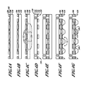
First, as shown in FIG. 2A , the mechanism layer 34 is etched using a known etchant (e.g., RIE (Reactive Ion Etch) or DRIE (Deep Reactive Ion Etch)) according to a predefined etching pattern(s). The dielectric layer 36 acts as an etch stop. Etching exposes appropriate actuator and/or sensor mechanical features (e.g. 38) in the mechanism layer 34. Next as shown in FIG. 2B , hydrogen fluoride (HF) etching and/or carbon dioxide (CO2) is used to etch away the dielectric below and around the features 38. Other etchants may be used provided the handle layer 32 acts as an etch stop.
Next, at a FIG. 2D , the silicon cover 40 is fusion or Au-eutectic bonded to the SOI wafer 30. The remaining portions of the dielectric layer 44 are bonded to non-feature components of the mechanical layer 34. Next, as shown in FIG. 2E , one or both of the handle layers 32 and 42 are etched away at locations relative to some of the non-feature portions of the mechanism layer 34 using a conventional wet etching process, such as potassium hydroxide (KOH). Next, one or both of the exposed dielectric material from the dielectric layers 36 and 44 are then etched away, using a standard etching process, to expose a portion of the non-featured portion of the mechanism layer 34. Next, metalized connectors 50 of a suitable metallization are applied to portions of the exposed non-featured sections of the mechanism layer 34. The metalized connectors 50 provide electrical connections to exposed electrical traces on the mechanism layer 34 that are in electrical communication with the active internal components (features 38). Lastly, dicing (not shown) occurs in order to separate sealed functional components and associated externally exposed metalized connectors 50.
Next, at FIG. 4D , the cover 120 is etched to expose a handle layer 122 at positions that would correspond to the active components 112 from the base wafer 102. Then, an optional mechanical isolation peripheral device 130, such as an isloator flange or isolation flange, is etched using DRIE or comparable etching technique. Next, at FIG. 4E , the cover 120 is attached to the base wafer 102 using a fusion bond, Au-eutectic bond, or comparable type of bonding process. Next, at FIG. 4F , a KOH etch or comparable etching technique is used to etch away a handle layer 110 of the base wafer 102 and the handle layer 122 is etched by DRIE process in order to complete the mechanical isolation around the periphery and to expose portions of a dielectric layer 124. The mechanical isolation around the periphery reduces the amount of mechanical loads that can impinge upon the components 112 when they are in a package. Then, the exposed dielectric material in the dielectric layer 124 is etched to form pit features 22 that expose the surface of the mechanism layer 106. Metalized contacts 140 are then applied to the exposed surface of the mechanism layer 106 in order to allow for connection of the active components 112 within corresponding hermetically sealed cavities to external devices (not shown). Dicing (not shown) of the entire package is then performed.
While the preferred embodiment of the invention has been illustrated and described, as noted above, many changes can be made without departing from the spirit and scope of the invention. For example, steps described and claimed may be performed in a different order without departing from the spirit and scope of the invention—e.g., doping of the active layer may be performed before etching the same layer. Accordingly, the scope of the invention is not limited by the disclosure of the preferred embodiment. Instead, the invention should be determined entirely by reference to the claims that follow.
Claims (8)
1. A method for forming a wafer level package device from only a base silicon-on-insulator (SOI) wafer and a cover plate wafer, the method comprising:
etching at least one active component in an active layer of the base SOI wafer, the SOI wafer having a handle layer separated from the active layer by a dielectric layer;
etching the dielectric layer in the vicinity of the formed at least one active component after etching of the at least one active component;
etching a dielectric layer of the cover plate wafer to form cavities to coincide with the at least one active component, the cover plate wafer having a handle layer attached to the cover plate wafer dielectric layer;
bonding the dielectric layer of a cover plate wafer to non-active components of the active layer;
etching at least one of the handle layers and corresponding dielectric layer to expose a portion of a surface of the active layer; and
forming a metallization on a portion of the exposed surface of the active layer,
wherein the at least one active component is included within a cavity,
thus the wafer level package device is formed from at most two SOI wafers.
2. The method of claim 1 , further comprising etching at least one isolator flange into the base wafer and the cover plate wafer at an exterior edge.
3. The method of claim 1 , wherein the cavity is a hermetically sealed cavity.
4. The method of claim 3 , wherein the cavity is defined by the handle layers on two sides and the active layer and the dielectric layers on all other sides.
5. A method for forming a wafer level package device from only two silicon-on-insulator (SOI) wafers, the method comprising:
forming at least one active component in an active layer of a base SOI wafer of the two SOI wafers, wherein the base SOI wafer comprises the active layer, a dielectric layer and a handle layer;
applying a dopant to the active layer;
anisotropically etching the handle layer of the base SOI wafer in the vicinity of the at least one active component;
etching an active layer and a dielectric layer of a cover plate SOI wafer of the two SOI wafers to form one or more cavities to coincide with the at least one active component of the base SOI wafer;
bonding the base SOI wafer to the cover plate SOI wafer;
etching at least one of the handle layers and corresponding dielectric layer to expose a surface of the corresponding active layer from the base SOI wafer or from the cover plate SOI wafer; and
forming a metallization on at least a portion of the exposed active layer,
wherein the at least one active component is included within a cavity,
thus the wafer level package device is formed from at most two SOI wafers.
6. The method of claim 5 , further comprising etching at least one of the SOI wafers in order to form one or more isolation flanges.
7. The method of claim 5 , wherein the cavity is a hermetically sealed cavity.
8. The method of claim 7 , wherein the cavity is defined by the handle layers on two sides and the active layer and the dielectric layers on all other sides.
Priority Applications (1)
| Application Number | Priority Date | Filing Date | Title |
|---|---|---|---|
| US12/965,569 US8685776B2 (en) | 2007-09-28 | 2010-12-10 | Wafer level packaged MEMS device |
Applications Claiming Priority (2)
| Application Number | Priority Date | Filing Date | Title |
|---|---|---|---|
| US11/864,725 US20090085194A1 (en) | 2007-09-28 | 2007-09-28 | Wafer level packaged mems device |
| US12/965,569 US8685776B2 (en) | 2007-09-28 | 2010-12-10 | Wafer level packaged MEMS device |
Related Parent Applications (1)
| Application Number | Title | Priority Date | Filing Date |
|---|---|---|---|
| US11/864,725 Continuation US20090085194A1 (en) | 2007-09-28 | 2007-09-28 | Wafer level packaged mems device |
Publications (2)
| Publication Number | Publication Date |
|---|---|
| US20110092018A1 US20110092018A1 (en) | 2011-04-21 |
| US8685776B2 true US8685776B2 (en) | 2014-04-01 |
Family
ID=40507256
Family Applications (2)
| Application Number | Title | Priority Date | Filing Date |
|---|---|---|---|
| US11/864,725 Abandoned US20090085194A1 (en) | 2007-09-28 | 2007-09-28 | Wafer level packaged mems device |
| US12/965,569 Active 2028-04-24 US8685776B2 (en) | 2007-09-28 | 2010-12-10 | Wafer level packaged MEMS device |
Family Applications Before (1)
| Application Number | Title | Priority Date | Filing Date |
|---|---|---|---|
| US11/864,725 Abandoned US20090085194A1 (en) | 2007-09-28 | 2007-09-28 | Wafer level packaged mems device |
Country Status (4)
| Country | Link |
|---|---|
| US (2) | US20090085194A1 (en) |
| EP (1) | EP2193542B1 (en) |
| JP (1) | JP2012506616A (en) |
| WO (1) | WO2009043062A2 (en) |
Cited By (8)
| Publication number | Priority date | Publication date | Assignee | Title |
|---|---|---|---|---|
| US9309106B2 (en) | 2013-07-08 | 2016-04-12 | Motion Engine Inc. | 3D MEMS device and method of manufacturing |
| US10214414B2 (en) | 2014-01-09 | 2019-02-26 | Motion Engine, Inc. | Integrated MEMS system |
| US10273147B2 (en) | 2013-07-08 | 2019-04-30 | Motion Engine Inc. | MEMS components and method of wafer-level manufacturing thereof |
| US10407299B2 (en) | 2015-01-15 | 2019-09-10 | Motion Engine Inc. | 3D MEMS device with hermetic cavity |
| US10768065B2 (en) | 2014-04-10 | 2020-09-08 | Mei Micro, Inc. | MEMS pressure sensor |
| US11287486B2 (en) | 2014-12-09 | 2022-03-29 | Motion Engine, Inc. | 3D MEMS magnetometer and associated methods |
| US11674803B2 (en) | 2014-06-02 | 2023-06-13 | Motion Engine, Inc. | Multi-mass MEMS motion sensor |
| US11852481B2 (en) | 2013-08-02 | 2023-12-26 | Motion Engine Inc. | MEMS motion sensor and method of manufacturing |
Families Citing this family (3)
| Publication number | Priority date | Publication date | Assignee | Title |
|---|---|---|---|---|
| US20090323170A1 (en) * | 2008-06-30 | 2009-12-31 | Qualcomm Mems Technologies, Inc. | Groove on cover plate or substrate |
| US8379392B2 (en) * | 2009-10-23 | 2013-02-19 | Qualcomm Mems Technologies, Inc. | Light-based sealing and device packaging |
| US9006015B2 (en) | 2013-01-24 | 2015-04-14 | Taiwan Semiconductor Manfacturing Company, Ltd. | Dual layer microelectromechanical systems device and method of manufacturing same |
Citations (18)
| Publication number | Priority date | Publication date | Assignee | Title |
|---|---|---|---|---|
| US20020014673A1 (en) * | 1992-04-08 | 2002-02-07 | Elm Technology Corporation | Method of making membrane integrated circuits |
| US6423563B2 (en) | 1998-05-08 | 2002-07-23 | Denso Corporation | Method for manufacturing semiconductor dynamic quantity sensor |
| US6552404B1 (en) * | 2001-04-17 | 2003-04-22 | Analog Devices, Inc. | Integratable transducer structure |
| US6718824B2 (en) | 2000-12-20 | 2004-04-13 | Nippon Soken, Inc. | Semiconductor dynamic quantity detecting sensor and manufacturing method of the same |
| US6789423B2 (en) | 2002-03-27 | 2004-09-14 | Samsung Electro-Mechanics Co., Ltd. | Micro inertia sensor and method of manufacturing the same |
| US20050037534A1 (en) * | 2001-01-02 | 2005-02-17 | Sawyer William D. | MEMS device and interposer and method for integrating MEMS device and interposer |
| US6892575B2 (en) * | 2003-10-20 | 2005-05-17 | Invensense Inc. | X-Y axis dual-mass tuning fork gyroscope with vertically integrated electronics and wafer-scale hermetic packaging |
| WO2005045885A2 (en) | 2003-10-31 | 2005-05-19 | Robert Bosch Gmbh | Anti-stiction technique for thin film and wafer-bonded encapsulated microelectromechanical systems |
| US20050179099A1 (en) * | 2004-02-12 | 2005-08-18 | Markus Lutz | Integrated getter area for wafer level encapsulated microelectromechanical systems |
| US20050205951A1 (en) * | 2004-03-18 | 2005-09-22 | Honeywell Internatioanl, Inc. | Flip chip bonded micro-electromechanical system (MEMS) device |
| JP2006147864A (en) | 2004-11-19 | 2006-06-08 | Fujikura Ltd | Semiconductor package and its manufacturing method |
| US20060128048A1 (en) * | 2004-02-17 | 2006-06-15 | Honeywell International, Inc. | Pyramid socket suspension |
| US20060163679A1 (en) * | 2005-01-21 | 2006-07-27 | Honeywell International, Inc. | High performance MEMS packaging architecture |
| US20060163680A1 (en) * | 2004-12-30 | 2006-07-27 | Jingkuang Chen | Micro-machined medical devices, methods of fabricating microdevices, and methods of medical diagnosis, imaging, stimulation, and treatment |
| US20060207087A1 (en) * | 2005-03-21 | 2006-09-21 | Honeywell International, Inc. | Method of manufacturing vibrating micromechanical structures |
| US20070218585A1 (en) | 2006-03-16 | 2007-09-20 | Commissariat A L'energie Atomique | Encapsulation in a hermetic cavity of a microelectronic composite, particularly of a mems |
| US20080099862A1 (en) | 2006-10-30 | 2008-05-01 | Denso Corporation | Physical quantity sensor and method for manufacturing the same |
| US20090025477A1 (en) * | 2007-07-26 | 2009-01-29 | Honeywell International Inc. | Sensor with position-independent drive electrodes in multi-layer silicon on insulator substrate |
Family Cites Families (3)
| Publication number | Priority date | Publication date | Assignee | Title |
|---|---|---|---|---|
| US5503285A (en) * | 1993-07-26 | 1996-04-02 | Litton Systems, Inc. | Method for forming an electrostatically force balanced silicon accelerometer |
| US6105427A (en) * | 1998-07-31 | 2000-08-22 | Litton Systems, Inc. | Micro-mechanical semiconductor accelerometer |
| US7303935B2 (en) * | 2005-09-08 | 2007-12-04 | Teledyne Licensing, Llc | High temperature microelectromechanical (MEM) devices and fabrication method |
-
2007
- 2007-09-28 US US11/864,725 patent/US20090085194A1/en not_active Abandoned
-
2008
- 2008-10-22 EP EP08833140.0A patent/EP2193542B1/en not_active Not-in-force
- 2008-10-22 JP JP2010527259A patent/JP2012506616A/en active Pending
- 2008-10-22 WO PCT/US2008/080691 patent/WO2009043062A2/en active Application Filing
-
2010
- 2010-12-10 US US12/965,569 patent/US8685776B2/en active Active
Patent Citations (21)
| Publication number | Priority date | Publication date | Assignee | Title |
|---|---|---|---|---|
| US20020014673A1 (en) * | 1992-04-08 | 2002-02-07 | Elm Technology Corporation | Method of making membrane integrated circuits |
| US6423563B2 (en) | 1998-05-08 | 2002-07-23 | Denso Corporation | Method for manufacturing semiconductor dynamic quantity sensor |
| US6718824B2 (en) | 2000-12-20 | 2004-04-13 | Nippon Soken, Inc. | Semiconductor dynamic quantity detecting sensor and manufacturing method of the same |
| US20050037534A1 (en) * | 2001-01-02 | 2005-02-17 | Sawyer William D. | MEMS device and interposer and method for integrating MEMS device and interposer |
| US6552404B1 (en) * | 2001-04-17 | 2003-04-22 | Analog Devices, Inc. | Integratable transducer structure |
| US6789423B2 (en) | 2002-03-27 | 2004-09-14 | Samsung Electro-Mechanics Co., Ltd. | Micro inertia sensor and method of manufacturing the same |
| US6892575B2 (en) * | 2003-10-20 | 2005-05-17 | Invensense Inc. | X-Y axis dual-mass tuning fork gyroscope with vertically integrated electronics and wafer-scale hermetic packaging |
| WO2005045885A2 (en) | 2003-10-31 | 2005-05-19 | Robert Bosch Gmbh | Anti-stiction technique for thin film and wafer-bonded encapsulated microelectromechanical systems |
| US20050179099A1 (en) * | 2004-02-12 | 2005-08-18 | Markus Lutz | Integrated getter area for wafer level encapsulated microelectromechanical systems |
| US7416910B2 (en) * | 2004-02-17 | 2008-08-26 | Honeywell International Inc. | Pyramid socket suspension |
| US20060128048A1 (en) * | 2004-02-17 | 2006-06-15 | Honeywell International, Inc. | Pyramid socket suspension |
| US20060123927A1 (en) * | 2004-02-17 | 2006-06-15 | Honeywell International, Inc. | Pyramid socket suspension |
| US20050205951A1 (en) * | 2004-03-18 | 2005-09-22 | Honeywell Internatioanl, Inc. | Flip chip bonded micro-electromechanical system (MEMS) device |
| JP2006147864A (en) | 2004-11-19 | 2006-06-08 | Fujikura Ltd | Semiconductor package and its manufacturing method |
| US20060163680A1 (en) * | 2004-12-30 | 2006-07-27 | Jingkuang Chen | Micro-machined medical devices, methods of fabricating microdevices, and methods of medical diagnosis, imaging, stimulation, and treatment |
| WO2006078564A1 (en) | 2005-01-21 | 2006-07-27 | Honeywell International Inc. | High performance mems packaging archetecture |
| US20060163679A1 (en) * | 2005-01-21 | 2006-07-27 | Honeywell International, Inc. | High performance MEMS packaging architecture |
| US20060207087A1 (en) * | 2005-03-21 | 2006-09-21 | Honeywell International, Inc. | Method of manufacturing vibrating micromechanical structures |
| US20070218585A1 (en) | 2006-03-16 | 2007-09-20 | Commissariat A L'energie Atomique | Encapsulation in a hermetic cavity of a microelectronic composite, particularly of a mems |
| US20080099862A1 (en) | 2006-10-30 | 2008-05-01 | Denso Corporation | Physical quantity sensor and method for manufacturing the same |
| US20090025477A1 (en) * | 2007-07-26 | 2009-01-29 | Honeywell International Inc. | Sensor with position-independent drive electrodes in multi-layer silicon on insulator substrate |
Non-Patent Citations (5)
| Title |
|---|
| Decision of Rejection and Translation of Decision of Rejection from the counterpart Japanese application No. 2010-527259, dated Dec. 10, 2013, 4 pages. |
| International Preliminary Report on Patentability from counterpart International application No. PCT/US2008/080691, dated Mar. 30, 2010. 5 pages. |
| Notification of Transmittal of the International Search Report and the Written Opinion from counterpart International application No. PCT/US2008/080691, dated Jul. 14, 2009. 10 pages. |
| Translation of Office Action from the counterpart Japanese application No. 2010-527259, dated Jul. 19, 2013. 2 pages. |
| Translation of Office Action from the counterpart Japanese application No. 2010-527259, dated Mar. 13, 2013. 1 page. |
Cited By (9)
| Publication number | Priority date | Publication date | Assignee | Title |
|---|---|---|---|---|
| US9309106B2 (en) | 2013-07-08 | 2016-04-12 | Motion Engine Inc. | 3D MEMS device and method of manufacturing |
| US10273147B2 (en) | 2013-07-08 | 2019-04-30 | Motion Engine Inc. | MEMS components and method of wafer-level manufacturing thereof |
| US11852481B2 (en) | 2013-08-02 | 2023-12-26 | Motion Engine Inc. | MEMS motion sensor and method of manufacturing |
| US10214414B2 (en) | 2014-01-09 | 2019-02-26 | Motion Engine, Inc. | Integrated MEMS system |
| US10768065B2 (en) | 2014-04-10 | 2020-09-08 | Mei Micro, Inc. | MEMS pressure sensor |
| US11579033B2 (en) | 2014-04-10 | 2023-02-14 | Mei Micro, Inc. | MEMS pressure sensor |
| US11674803B2 (en) | 2014-06-02 | 2023-06-13 | Motion Engine, Inc. | Multi-mass MEMS motion sensor |
| US11287486B2 (en) | 2014-12-09 | 2022-03-29 | Motion Engine, Inc. | 3D MEMS magnetometer and associated methods |
| US10407299B2 (en) | 2015-01-15 | 2019-09-10 | Motion Engine Inc. | 3D MEMS device with hermetic cavity |
Also Published As
| Publication number | Publication date |
|---|---|
| JP2012506616A (en) | 2012-03-15 |
| US20110092018A1 (en) | 2011-04-21 |
| WO2009043062A2 (en) | 2009-04-02 |
| EP2193542A2 (en) | 2010-06-09 |
| WO2009043062A3 (en) | 2009-09-03 |
| US20090085194A1 (en) | 2009-04-02 |
| EP2193542A4 (en) | 2014-07-23 |
| EP2193542B1 (en) | 2015-09-23 |
Similar Documents
| Publication | Publication Date | Title |
|---|---|---|
| US8685776B2 (en) | Wafer level packaged MEMS device | |
| US7247246B2 (en) | Vertical integration of a MEMS structure with electronics in a hermetically sealed cavity | |
| US7104129B2 (en) | Vertically integrated MEMS structure with electronics in a hermetically sealed cavity | |
| US7767484B2 (en) | Method for sealing and backside releasing of microelectromechanical systems | |
| US8710599B2 (en) | Micromachined devices and fabricating the same | |
| US8372677B2 (en) | Three-axis accelerometers and fabrication methods | |
| CN103221795B (en) | Microelectromechanical pressure sensor including reference capacitor | |
| US9452920B2 (en) | Microelectromechanical system device with internal direct electric coupling | |
| US20100193884A1 (en) | Method of Fabricating High Aspect Ratio Transducer Using Metal Compression Bonding | |
| EP1884994B1 (en) | Semiconductor device and method of manufacturing the same | |
| JP2014523815A (en) | Process for a sealed MEMS device comprising a portion exposed to the environment | |
| US20050287760A1 (en) | Method for fabricating high aspect ratio MEMS device with integrated circuit on the same substrate using post-CMOS process | |
| JP2008132587A (en) | Method of manufacturing wafer-level vacuum packaged device | |
| JP4784641B2 (en) | Semiconductor device and manufacturing method thereof | |
| US20150276533A1 (en) | Low Pressure Sensor and Flow Sensor | |
| CN104003348A (en) | Method for mems structure with dual-level structural layer and acoustic port | |
| JP2017021010A (en) | Low pressure sensor and flow sensor | |
| US20080142913A1 (en) | Z offset mems devices and methods | |
| US11267697B2 (en) | Use of an uncoupling structure for assembling a component having a casing | |
| JP2012026956A (en) | Pressure sensor manufacturing method and pressure sensor | |
| US7531424B1 (en) | Vacuum wafer-level packaging for SOI-MEMS devices | |
| JP5827365B2 (en) | Method for forming device packaged at wafer level | |
| US8430255B2 (en) | Method of accurately spacing Z-axis electrode | |
| KR100324716B1 (en) | Packaging Methods for Microstructures and Microsystems | |
| CN100422070C (en) | Mobile microstructure cosupported by silicon and silicon dioxide, and its production method |
Legal Events
| Date | Code | Title | Description |
|---|---|---|---|
| STCF | Information on status: patent grant |
Free format text: PATENTED CASE |
|
| MAFP | Maintenance fee payment |
Free format text: PAYMENT OF MAINTENANCE FEE, 4TH YEAR, LARGE ENTITY (ORIGINAL EVENT CODE: M1551) Year of fee payment: 4 |
|
| MAFP | Maintenance fee payment |
Free format text: PAYMENT OF MAINTENANCE FEE, 8TH YEAR, LARGE ENTITY (ORIGINAL EVENT CODE: M1552); ENTITY STATUS OF PATENT OWNER: LARGE ENTITY Year of fee payment: 8 |