US8722261B2 - Recycler for direct methanol fuel cell and method of operating the same - Google Patents
Recycler for direct methanol fuel cell and method of operating the same Download PDFInfo
- Publication number
- US8722261B2 US8722261B2 US12/045,900 US4590008A US8722261B2 US 8722261 B2 US8722261 B2 US 8722261B2 US 4590008 A US4590008 A US 4590008A US 8722261 B2 US8722261 B2 US 8722261B2
- Authority
- US
- United States
- Prior art keywords
- housing
- gas
- liquid
- recycler
- rotor
- Prior art date
- Legal status (The legal status is an assumption and is not a legal conclusion. Google has not performed a legal analysis and makes no representation as to the accuracy of the status listed.)
- Expired - Fee Related, expires
Links
Images


Classifications
-
- H—ELECTRICITY
- H01—ELECTRIC ELEMENTS
- H01M—PROCESSES OR MEANS, e.g. BATTERIES, FOR THE DIRECT CONVERSION OF CHEMICAL ENERGY INTO ELECTRICAL ENERGY
- H01M8/00—Fuel cells; Manufacture thereof
- H01M8/06—Combination of fuel cells with means for production of reactants or for treatment of residues
- H01M8/0662—Treatment of gaseous reactants or gaseous residues, e.g. cleaning
- H01M8/0668—Removal of carbon monoxide or carbon dioxide
-
- H—ELECTRICITY
- H01—ELECTRIC ELEMENTS
- H01M—PROCESSES OR MEANS, e.g. BATTERIES, FOR THE DIRECT CONVERSION OF CHEMICAL ENERGY INTO ELECTRICAL ENERGY
- H01M8/00—Fuel cells; Manufacture thereof
- H01M8/02—Details
-
- B—PERFORMING OPERATIONS; TRANSPORTING
- B01—PHYSICAL OR CHEMICAL PROCESSES OR APPARATUS IN GENERAL
- B01D—SEPARATION
- B01D19/00—Degasification of liquids
- B01D19/0042—Degasification of liquids modifying the liquid flow
- B01D19/0052—Degasification of liquids modifying the liquid flow in rotating vessels, vessels containing movable parts or in which centrifugal movement is caused
-
- B—PERFORMING OPERATIONS; TRANSPORTING
- B01—PHYSICAL OR CHEMICAL PROCESSES OR APPARATUS IN GENERAL
- B01D—SEPARATION
- B01D45/00—Separating dispersed particles from gases or vapours by gravity, inertia, or centrifugal forces
- B01D45/12—Separating dispersed particles from gases or vapours by gravity, inertia, or centrifugal forces by centrifugal forces
- B01D45/14—Separating dispersed particles from gases or vapours by gravity, inertia, or centrifugal forces by centrifugal forces generated by rotating vanes, discs, drums or brushes
-
- H—ELECTRICITY
- H01—ELECTRIC ELEMENTS
- H01M—PROCESSES OR MEANS, e.g. BATTERIES, FOR THE DIRECT CONVERSION OF CHEMICAL ENERGY INTO ELECTRICAL ENERGY
- H01M4/00—Electrodes
- H01M4/02—Electrodes composed of, or comprising, active material
- H01M4/04—Processes of manufacture in general
- H01M4/043—Processes of manufacture in general involving compressing or compaction
- H01M4/0435—Rolling or calendering
-
- H—ELECTRICITY
- H01—ELECTRIC ELEMENTS
- H01M—PROCESSES OR MEANS, e.g. BATTERIES, FOR THE DIRECT CONVERSION OF CHEMICAL ENERGY INTO ELECTRICAL ENERGY
- H01M8/00—Fuel cells; Manufacture thereof
- H01M8/04—Auxiliary arrangements, e.g. for control of pressure or for circulation of fluids
-
- H—ELECTRICITY
- H01—ELECTRIC ELEMENTS
- H01M—PROCESSES OR MEANS, e.g. BATTERIES, FOR THE DIRECT CONVERSION OF CHEMICAL ENERGY INTO ELECTRICAL ENERGY
- H01M8/00—Fuel cells; Manufacture thereof
- H01M8/10—Fuel cells with solid electrolytes
- H01M8/1009—Fuel cells with solid electrolytes with one of the reactants being liquid, solid or liquid-charged
- H01M8/1011—Direct alcohol fuel cells [DAFC], e.g. direct methanol fuel cells [DMFC]
-
- Y—GENERAL TAGGING OF NEW TECHNOLOGICAL DEVELOPMENTS; GENERAL TAGGING OF CROSS-SECTIONAL TECHNOLOGIES SPANNING OVER SEVERAL SECTIONS OF THE IPC; TECHNICAL SUBJECTS COVERED BY FORMER USPC CROSS-REFERENCE ART COLLECTIONS [XRACs] AND DIGESTS
- Y02—TECHNOLOGIES OR APPLICATIONS FOR MITIGATION OR ADAPTATION AGAINST CLIMATE CHANGE
- Y02E—REDUCTION OF GREENHOUSE GAS [GHG] EMISSIONS, RELATED TO ENERGY GENERATION, TRANSMISSION OR DISTRIBUTION
- Y02E60/00—Enabling technologies; Technologies with a potential or indirect contribution to GHG emissions mitigation
- Y02E60/10—Energy storage using batteries
-
- Y—GENERAL TAGGING OF NEW TECHNOLOGICAL DEVELOPMENTS; GENERAL TAGGING OF CROSS-SECTIONAL TECHNOLOGIES SPANNING OVER SEVERAL SECTIONS OF THE IPC; TECHNICAL SUBJECTS COVERED BY FORMER USPC CROSS-REFERENCE ART COLLECTIONS [XRACs] AND DIGESTS
- Y02—TECHNOLOGIES OR APPLICATIONS FOR MITIGATION OR ADAPTATION AGAINST CLIMATE CHANGE
- Y02E—REDUCTION OF GREENHOUSE GAS [GHG] EMISSIONS, RELATED TO ENERGY GENERATION, TRANSMISSION OR DISTRIBUTION
- Y02E60/00—Enabling technologies; Technologies with a potential or indirect contribution to GHG emissions mitigation
- Y02E60/30—Hydrogen technology
- Y02E60/50—Fuel cells
Definitions
- aspects of the present invention relate to a recycler for a direct methanol fuel cell (DMFC), which uses methanol as a fuel, to recycle unreacted methanol recovered from a stack and H 2 O, and a method of operating the same.
- DMFC direct methanol fuel cell
- a fuel cell is an electric generator that changes chemical energy of a fuel into electrical energy through a chemical reaction.
- the fuel cell continuously generates electricity as long as fuel is supplied.
- a direct methanol fuel cell is an apparatus that uses methanol as a fuel to generate electricity through a reaction between the fuel directly fed to an anode and oxygen supplied to a cathode of the DMFC.
- DMFC direct methanol fuel cell
- electrons are generated through Chemical Reaction 1 as indicated below, and the electrons move to the cathode along a moving path and generate H 2 O through Chemical Reaction 2 as indicated below.
- a load is applied to the moving path, work can be done using the generated electricity.
- Methanol can be supplied to the anode by pumping liquid state methanol, and such DMFC is referred to as an active type DMFC.
- vaporized methanol may be induced to flow into the anode as methanol vaporizes at room temperature, and such DMFC is referred to as a passive type DMFC.
- an active type DMFC will be described.
- FIG. 1 is a functional block diagram of the configuration of an active DMFC.
- a stack 20 formed by stacking a plurality of the single assemblies, is used.
- a plurality of unit cells are stacked such that in each of the unit cells, an anode and a cathode are formed respectively on opposite sides of an electrolyte membrane, and thus, a large power is output by adding the electricity generated from each of the unit cells.
- the active DMFC includes an air pump 60 to supply air as a source of oxygen to the cathode and a cartridge 30 where methanol to be supplied to the anode is stored.
- the cartridge 30 high concentration methanol, for example, 100% methanol, is stored.
- the active DMFC includes a storage tank 70 to store a diluted fuel, having a concentration of 0.5 to 2M, to be supplied to the anode of the stack 20 through a supply pump 50 .
- the diluted fuel is made by adding water to the high concentration methanol supplied from the cartridge 30 through a fuel pump 40 to obtain the diluted fuel with a concentration of 0.5 to 2M.
- the active DMFC includes a heat exchanger 80 to decrease the temperature of a gas-liquid mixture discharged from the stack 20 . That is, the heat exchanger 80 condenses steam in the gas-liquid mixture discharged from the stack 20 by decreasing the high temperature of the gas-liquid mixture.
- the active DMFC includes a recycler 10 to recycle unreacted methanol that is discharged from the stack 20 after having generated electricity and H 2 O, which is a by-product from the electricity generation reaction.
- the recycler 10 is also referred to as a gas-liquid separator since the recycler 10 separates unreacted methanol and water (by-product) from the gas-liquid mixture recovered from the stack 20 to reuse the unreacted methanol and water to dilute the high concentration methanol.
- low concentration methanol can be stored in the cartridge 30 .
- the capacity of the cartridge 10 must be very large.
- high concentration methanol is stored in the cartridge 30 and then is gradually supplied to the storage tank 70 to be diluted.
- FIGS. 2A and 2B are cross-sectional views of the structure of the conventional recyclers 10 employed in the active DMFC of FIG. 1 .
- a gas and liquid are separated by gravity; that is, the gas is discharged through an upper port 11 a of a housing 11 and the liquid, which is denser than the gas, is discharged through a lower port 11 b of the housing 11 .
- the liquid includes methanol that did not react in the stack 20 , and water produced as a by-product, and the gas includes air supplied as an oxygen source and CO 2 generated from a chemical reaction at the anode.
- the separated liquid is appropriately mixed with high concentration methanol supplied to the storage tank 70 from the cartridge 30 , so as to have an appropriate low concentration methanol needed at the stack 20 for electricity generation, and as described above, the mixture is re-supplied to the stack by the supply pump 50 .
- the structure of the recycler 10 a of FIG. 2A has an advantage of structural simplicity as recycler 10 a uses gravity to function; however, the lower port 11 b , through which the liquid is discharged, must be disposed in the direction of gravity. Thus, recycler 10 a is limited by the direction of gravity.
- the lower port 11 b of the conventional recycler 10 a may be moved such that the lower port 11 b is disposed in a direction opposite to the direction of gravity when the mobile apparatus is being used. In such case, the conventional recycler 10 a cannot appropriately perform the function of gas-liquid separation.
- FIG. 2B The structure of FIG. 2B is of another conventional recycler 10 b that is designed to address the above problem. That is, as depicted in FIG. 2B , the conventional recycler 10 b does not use gravity to function, instead, a hydrophobic membrane 12 a is installed in one port of a housing 12 and a hydrophilic membrane 12 b is installed in another port of the housing 12 so that gas can be discharged through the hydrophobic membrane 12 a and liquid can be discharged through the hydrophilic membrane 12 b . In this way, the gas-liquid separation can be achieved regardless of the direction of gravity, and thus, the active DMFC can be applied to a mobile apparatus.
- aspects of the present invention provide a DMFC having a recycler that can be used regardless of its orientation and can effectively maintain performance for a long period of time.
- a recycler for a direct methanol fuel cell comprising: a housing in which a gas-liquid mixture recovered from a stack is accommodated; a rotor rotatably mounted in the housing; and a motor to rotate the rotor, wherein, when the rotor is rotated by the motor, a phase separation occurs such that liquid in the gas-liquid mixture is mainly in an outer region of the housing due to a centrifugal force and gas is collected in the center region of the housing.
- the housing may comprise: a first inlet port through which the gas-liquid mixture enters; a second inlet port through which high concentration methanol enters to replenish fuel to the stack; and a gas outlet port for discharging gas collected in the center region of the housing; and a liquid outlet port for discharging liquid gathered in the outer region of the housing.
- a discharge path connected to the gas outlet port may comprise bending portions to change the direction of the gas.
- a portion of a main body of the motor may be installed partially in the housing.
- a gap between an inner wall of the housing and an outer circumference of the rotor may be formed sufficiently narrow to a level of 0.2 to 1 mm.
- the rotor corresponds to the inside surfaces of the housing.
- the rotor may include a plurality of holes formed to extend therethrough.
- the housing may be formed of a metal, and may have a thickness of 0.2 to 0.5 mm.
- the housing may include fins and/or a cooling fan on the outside the housing to increase cooling efficiency.
- the recycler may further comprise a level sensor to measure a liquid level in the housing and a gravitational direction detection sensor to detect a gravitational direction of the housing.
- a method of operating a recycler for a DMFC comprising: preparing a recycler comprising a housing in which a gas-liquid mixture recovered from a stack is separated by centrifugal force applied to the gas-liquid mixture by a rotor rotatably mounted in the housing or by gravity, and a gravitational direction detection sensor to detect a gravitational direction of the housing; detecting whether the discharge direction of a liquid outlet port is aligned with a gravitation direction using the gravitational direction detection sensor; and rotating the rotor to apply centrifugal force to the gas-liquid mixture if the discharge direction of the liquid outlet port is not sufficiently aligned with the gravitational direction.
- the method may further comprise discharging gas separated from the gas-liquid mixture by opening a gas outlet port provided in the center region of the housing and discharging liquid separated from the gas-liquid mixture by opening a liquid outlet port provided in an outer region of the housing.
- the method may further comprise discharging the gas that has left from the gas outlet port along a discharge path that is bent at least once.
- the method may further comprise detecting a liquid level in the housing to determine whether the liquid level is suitable for a normal operation using a level sensor to measure the liquid level in the housing before opening the liquid outlet port.
- FIG. 1 is a functional block diagram of the configuration of a conventional active direct methanol fuel cell (DMFC);
- DMFC direct methanol fuel cell
- FIGS. 2A and 2B are schematic cross-sectional views of conventional recyclers employed in the active DMFC of FIG. 1 ;
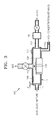
- FIG. 3 is a schematic cross-sectional view of a structure of a recycler for a direct methanol fuel cell (DMFC), according to an embodiment of the present invention
- FIGS. 4A and 4B are respectively an exploded perspective view showing parts of the recycler and a perspective view of a combined state of the recycler of FIG. 3 ;
- FIG. 5 is a flowchart for explaining a method of the recycler of FIG. 3 , according to an embodiment of the present invention.
- FIG. 6 is a perspective view showing the configuration of a gas outlet port of the recycler of FIG. 3 , according to an embodiment of the present invention.
- FIG. 3 is a schematic cross-sectional view of a structure of a recycler 100 for a direct methanol fuel cell (DMFC), according to an embodiment of the present invention.
- FIGS. 4A and 4B are respectively an exploded perspective view showing parts of the recycler 100 and a perspective view of a combined state of the recycler 100 of FIG. 3 .
- the recycler 100 for a DMFC according to an embodiment of the present invention includes a housing 110 , a rotor 120 rotatably mounted in the housing 110 and corresponding to the inside surfaces of the housing 110 , and a motor 130 that rotates the rotor 120 .
- the recycler 100 does not separate gas and liquid by gravity or membranes but instead has a configuration in which gas and liquid are separated using a centrifugal force generated by rotating the rotor 120 .
- a portion of the motor 130 is inserted into the housing 110 to reduce an overall volume of the recycler 100 , but the recycler 100 is not limited thereto such that the motor 130 need not be inserted into the housing 110 .
- the recycler 100 is not limited to rotating the rotor 120 with the motor 130 , but the rotor 120 may be rotated by other mechanical devices or by manual manipulation.
- the housing 110 is of a generally cylindrical shape having two generally parallel and flat surfaces, the gas outlet port 114 is centrally disposed in one of the two surfaces and the motor 130 is centrally disposed in the other of the two surface, and a side that connects to the peripheries of the two generally parallel and flat surfaces.
- the housing 110 includes a first inlet port 111 through which a gas-liquid mixture recovered from the stack 20 (refer to FIG. 1 ) enters, a second inlet port 112 through which high concentration methanol (for example 100% methanol) supplied from the cartridge 30 (refer to FIG.
- the first inlet port 111 , the second inlet port 112 , and the liquid outlet port may be located generally in the side of the housing 110 , but such locations are not limited thereto.
- the second inlet port 112 is located in a periphery of one of the two generally parallel and flat surfaces of the housing 110 .
- the first inlet port and the liquid outlet port 113 may be located on oppositely on the side of the housing 110 but are not limited thereto.
- the recycler 100 also includes a liquid level sensor 140 and a gravitational direction detection sensor 150 , which will be described in greater detail in association with FIG. 4B . Further, a supply pump 50 similar to that in FIG. 1 , is also shown connected to the liquid outlet port 113 .
- a gas-liquid mixture from the stack 20 and high concentration methanol from the cartridge 30 respectively enter through the first and second inlet ports 111 and 112 , and liquid and gas which are centrifugally separated due to the rotation of the rotor 120 are respectively discharged through the liquid outlet port 113 and the gas outlet port 114 .
- the recycler 100 is supplied with the high concentration methanol from the cartridge 30
- the recycler 100 need not be supplied with the high concentration methanol from the cartridge 30 such that high concentration methanol may be mixed with the liquid discharged from the liquid outlet port 113 in a storage tank similar to as shown in FIG. 1 .
- a sufficiently narrow gap d of about 0.2 to 1 mm is formed between the rotor 120 and an inner wall of the housing 110 , and the rotor 120 has a shape similar to the internal shape of the housing 110 such that the rotor includes a portion facing an upper surface, a portion facing side surfaces, and a portion facing a lower surface of the housing 110 .
- the narrow gap d prevents liquid from flowing to the gas outlet port 114 and facilitates quick transmission of a centrifugal force to the liquid.
- the narrow gap d is formed in order to effectively transmit a centrifugal force generated by rotation of the rotor 120 to liquid components of the gas-liquid mixture when the gas-liquid mixture is injected into the narrow gap d between the rotor 120 and the housing 110 from the stack 20 .
- the liquid component in the gas-liquid mixture is rapidly separated from the gas and moved in an outer direction away from the axis of rotation of the rotor 120 , and thus the liquid component does not flow into the gas outlet port 114 formed in the center of the housing 110 .
- the rotor 120 has a shape to achieve uniform gas-liquid separation regardless of the orientation of the recycler 100 . That is, regardless of the orientation of the recycler 100 , when liquid contacts the inner wall of the housing 110 due to gravity, the rotor 120 simultaneously applies a centrifugal force on the liquid from and is moved in an outer direction of the rotor 120 .
- the rotor 120 may be hollow and have a structure in which many holes are formed on an outer circumference of the rotor 120 . In this way, an amount of liquid that can be accommodated in the housing 110 can be increased.
- the housing 110 of a recycler 200 has a generally cylindrical shape. Internally, the housing accommodates the similarly shaped rotor 120 so that appropriate centrifugal force may be applied to the gas-liquid mixture entering the first inlet port 111 to separate the liquid from the gas.
- the motor 130 is shown, in FIG. 4A , to be at least partially disposed in the housing 110 so as to decrease the size of the recycler 100 but the motor 130 is not limited thereto.
- the motor 130 is connected to and rotates the rotor 120 to apply centrifugal force to the gas-liquid mixture.
- the rotor 120 may have any number of shapes to sufficiently separate the liquid from the gas, but is shown having a three-dimensional cobweb-like shape or an open, generally cylindrical shape.
- a generally flat, circular surface of the rotor 120 corresponds to an internal side of the generally flat surface of the housing 110 in which the gas outlet port 114 is disposed.
- the generally flat, circular surface of the rotor 120 may have a plurality of holes disposed therein.
- the rotor 120 has a side surface to correspond to an internal surface of the side of the housing 110 .
- the side surface of the rotor 120 may also have a plurality of holes disposed therein.
- the rotor 120 has another generally flat, circular surface to correspond to an internal surface of the other generally flat surface of the housing 110 in which the motor 130 is disposed.
- the other generally flat, circular surface of the rotor 120 includes a hole to accommodate the motor 130 .
- the other generally flat, circular surface of the rotor 120 need not include the hole to accommodate the motor 130 and may be similar to the generally flat, circular surface of the rotor 120 that corresponds to the internal side of the generally flat surface of the housing 110 in which the gas outlet port 114 is disposed.
- the housing 110 may be formed of a metal having high thermal conductivity because a gas-liquid mixture entering the housing 110 from the stack 20 normally has a temperature of 60 to 65° C.; however, when the temperature of the gas-liquid mixture is high, the liquid can be included in the gas, and thus, the amount of liquid that can be discharged together with the gas through the gas outlet port 114 can be increased. Therefore, if the housing 110 is formed of a metal in order to facilitate heat dissipation, the temperature of the gas-liquid mixture can be decreased. Thus, the amount of liquid included in the gas can be decreased, and accordingly, the amount of fuel leaving together with the gas can be decreased. Also, the metal should not be reactive with methanol.
- the housing 110 may have a thickness of 0.2 to 0.5 mm.
- Fins and/or a cooling fan may further be included on an outside of the housing 110 to increase cooling efficiency.
- water recovery efficiency can be increased by decreasing the temperature of the gas-liquid mixture in the recycler 100 , and furthermore, without the additional heat exchanger 80 , the recycler 100 can perform the gas-liquid separation function and the heat exchanging function.
- the housing 110 of a recycler 300 again has a generally cylindrical inside while the outside may include a flat side but need not.
- the gas outlet port 114 is centrally located in one of the generally flat surfaces of the housing 110 , and, while not shown, the motor 130 is located in the other of the generally flat surfaces of the housing 110 .
- the second inlet port 112 and the liquid outlet port 113 are located peripherally in one of the generally flat surfaces of the housing 110 , but neither is limited thereto.
- the recycler may further include a level sensor 140 to measure a liquid level in the housing 110 .
- the level sensor 140 is not disposed in a gravitational direction; however, the level sensor 140 is disposed in a radial direction of the rotor 120 .
- Liquid is filled from an inner surface of the side of the housing 110 due to the centrifugal force generated by the rotation of the rotor 120 by the motor 130 and thereby establishes a peripheral depth, i.e., the depth of the liquid with reference to the inner surface of the side or inside periphery of the housing 110 .
- a peripheral depth i.e., the depth of the liquid with reference to the inner surface of the side or inside periphery of the housing 110 .
- the recycler 300 may further include a gravitational direction detection sensor 150 to detect a gravitational direction.
- the inclusion of the gravitational direction detection sensor 150 saves power, and a method of using the gravitational direction detection sensor 150 will be described in detail later.
- a gas-liquid mixture from the stack 20 and high concentration methanol from the cartridge 30 respectively enter the housing 110 through the first and second inlet ports 111 and 112 .
- the rotor 120 starts to be rotated by the motor 130 .
- the gas-liquid mixture begins to rotate in the rotation direction of the rotor 120 .
- the liquid which is denser than the gas, flows towards outer regions of the housing 110 and the gas concentrates in the center of the housing 110 .
- the liquid is separated from the gas, that is, low concentration methanol, in which methanol and water are appropriately mixed, is sent to the stack 20 through the liquid outlet port 113 , and the gas separated from the liquid is exhausted to the outside of the housing 110 through the gas outlet port 114 .
- aspects of the present invention need not be limited thereto such that, if there is no high concentration methanol supplied to the recycler 300 , the liquid containing methanol may be sent through the liquid outlet port 113 to a storage tank (similar to storage tank 70 of FIG. 1 ) to be mixed with high concentration methanol to an appropriate methanol concentration before being sent to the stack 20 .
- water may be added to the recycler to adjust the concentration of the methanol to be supplied to the storage tank 70 or the stack 20 . Since such separation in the recycler 300 uses centrifugal force generated by the rotation of the rotor 120 , the separation can be continued regardless of the orientation of the housing 110 .
- the gravitational direction detection sensor 150 detects whether the discharge direction of the liquid outlet port 113 is aligned with the gravitational direction.
- the recycler 300 need not be limited thereto such that the recycler 300 may separate the liquid from the gas-liquid mixture according to gravity despite not being aligned completely with the gravitational direction, i.e., the alignment of the liquid outlet port 113 need only be sufficiently aligned with the gravitational direction to separate the liquid from the gas-liquid mixture in order to stop the rotor 120 and save power.
- the gravitational direction detection sensor 150 may be activated to save power and be sequentially performed as indicated in the flowchart of an operation method of the recycler according to aspects of the present invention, as shown in FIG. 5 .
- FIG. 5 is a flowchart of an operation method of the recycler 100 of FIG. 3 , according to an embodiment of the present invention; however, such method may apply to all embodiments and aspects of the present invention.
- the recycler 100 that performs gas-liquid separation using centrifugal force generated by the rotor 120 in the housing 110 and includes the gravitational direction detection sensor 150 is prepared (S 1 ).
- a liquid level in the housing 110 is measured by the level sensor 140 while rotating the rotor 120 (S 2 ) in order to prevent gas from entering the stack 20 because if the liquid outlet port 113 is opened when the liquid level in the housing 110 is very low, a large amount of gas, sufficient to adversely affect the stack 20 , can enter the stack 20 through the liquid outlet port 113 .
- the liquid level in the housing 110 is measured in terms of whether the liquid level is at a normal operation level (S 3 ). If the liquid level is not at a normal operation level, the operation of the rotor 120 is stopped (S 4 ), and a warning lamp is enabled to indicate an insufficient liquid level (S 5 ).
- aspects of the present invention are not limited thereto such that high concentration methanol and/or water may be supplied to the recycler 100 to increase the liquid level therein so as to continue operation of the system.
- the discharge direction of the liquid outlet port 113 is detected in terms of whether the discharge direction of the liquid outlet port 113 is aligned with the gravitational direction using the gravitational direction detection sensor 150 (S 6 ).
- the alignment can be set as being a predetermined angle between the discharge direction of the liquid outlet port 113 and the gravitational direction, i.e., the discharge direction of the liquid outlet port 113 need not be directly or substantially aligned with the gravitational direction.
- the gas-liquid separation is performed by rotating the rotor 120 as described above (S 7 ). Again, however, the discharge direction of the liquid outlet port 113 need not be directly or substantially aligned with the gravitational direction to use gravity to separate the liquid from the gas. Otherwise, if it is determined that the discharge direction of the liquid outlet port 113 is aligned with the gravitational direction in operation S 6 , the natural phase separation is performed using gravity without rotating the rotor 120 , and thus, power consumption is decreased by the recycler 100 .
- the orientation of the housing 110 can be occasionally changed, and thus, whether the rotor 120 is rotated can be determined by continuously measuring the direction of gravity.
- a discharge path 115 which is connected to the gas outlet port 114 , may be bent around the housing 110 so that the discharge direction of the discharge path 115 is bent at least once.
- the discharge direction of the discharge path 115 is bent at an angle, i.e., the discharge path is 115 not a straight discharge path, a sudden flow of a large amount of liquid into the gas outlet port 114 can be prevented from flowing completely through the discharge path 115 even though there is a sudden orientational change of the housing 110 .
- the bent discharge path 115 prevents the risk a large amount of liquid from entering into the gas outlet port 114 and flowing completely through the discharge path 115 .
- the discharge path 115 of a recycler 400 is bent around or about the housing 110 from the gas outlet port 114 .
- the discharge path 115 described and illustrated herein as having multiple 90° bends about the housing 110 the discharge path 115 from the gas outlet port need not be limited thereto such that one bend may be sufficient to prevent a flow of an amount of liquid from the gas outlet port 114 through the discharge path 115 .
- the gas discharge port 114 is centrally located in a flat surface of the generally cylindrical housing 110 .
- the discharge path 115 bends and extends radially from the gas outlet port 114 .
- the discharge path 115 bends about the periphery of the flat surface of the generally cylindrical housing 110 to extend down a side thereof.
- the discharge path 115 bends again to extend along an opposite side of the generally cylindrical housing 110 along another generally flat surface opposite the generally flat surface in which the gas outlet port 114 is disposed.
- the discharge path 115 then bends again at the periphery of the other generally flat surface to extend along the side of the generally cylindrical housing 110 toward the generally flat surface in which the gas outlet port 114 is disposed.
- the discharge path 115 then bends toward the gas outlet port 114 to extend toward the center region from the periphery of the generally flat surface in which the gas outlet port 114 is disposed.
- the discharge path 115 bends toward the periphery again, bends along the side of the generally cylindrical housing 110 at the periphery of the generally flat surface, bends along the other generally flat surface to extend thereacross, bends again at the periphery of the other generally flat surface to extend along the side of the housing 110 , and bends toward the center region to bend finally to generally align with the exit from the gas outlet port 114 .
- Each of the bends as illustrated in FIG. 6 is generally 90°; however, aspects of the present invention are not limited thereto such that the bends in the discharge path 115 may be greater than or less than 90° and need only be sufficient to prevent liquid from flowing along the discharge path 115 while the orientation of the housing 110 is changed.
- a DMFC having a recycler that can be used regardless of the gravitational direction and can maintain a high performance for a time can be realized.
- the recycler according to aspects of the present invention has the following and/or other advantages: First, since gas-liquid separation is performed due to a centrifugal force generated by forced rotation of a rotor, a liquid outlet port does not need to align with the gravitational direction, and thus, the recycler can be used effectively in a mobile apparatus regardless of its orientation. Second, since a membrane of which performance is rapidly reduced over time is not used, the recycler can effectively perform for a long service life. Third, since discharge paths connected to a gas outlet port are bent as described above, an unexpected liquid leakage to the gas outlet port can be prevented.
- the recycler can also perform the gas-liquid separation using gravity by including a gravitational direction detection sensor to detect when a liquid outlet port of the housing is aligned with a gravitational direction even when the rotor is not operating.
- an additional storage space to store liquid separated from the gas-liquid mixture need not be included as the housing of the recycler itself performs as a storage space, and thus, the volume of a DMFC can be reduced and a simple DMFC structure can be realized.
- methanol having a uniform concentration can be supplied to a stack.
Abstract
Description
CH3OH+H2O
3/2O2+6H++6e −
Claims (22)
Applications Claiming Priority (3)
| Application Number | Priority Date | Filing Date | Title |
|---|---|---|---|
| KR2007-98373 | 2007-09-28 | ||
| KR1020070098373A KR101473318B1 (en) | 2007-09-28 | 2007-09-28 | Recycler for direct methanol fuel cell and managing method thereof |
| KR10-2007-0098373 | 2007-09-28 |
Publications (2)
| Publication Number | Publication Date |
|---|---|
| US20090087703A1 US20090087703A1 (en) | 2009-04-02 |
| US8722261B2 true US8722261B2 (en) | 2014-05-13 |
Family
ID=40149714
Family Applications (1)
| Application Number | Title | Priority Date | Filing Date |
|---|---|---|---|
| US12/045,900 Expired - Fee Related US8722261B2 (en) | 2007-09-28 | 2008-03-11 | Recycler for direct methanol fuel cell and method of operating the same |
Country Status (5)
| Country | Link |
|---|---|
| US (1) | US8722261B2 (en) |
| EP (1) | EP2043186B1 (en) |
| JP (1) | JP5546751B2 (en) |
| KR (1) | KR101473318B1 (en) |
| CN (1) | CN101399348A (en) |
Cited By (2)
| Publication number | Priority date | Publication date | Assignee | Title |
|---|---|---|---|---|
| US9583775B2 (en) | 2012-10-24 | 2017-02-28 | Samsung Electronics Co., Ltd. | Fuel cell system and electronic device controlling the same |
| US20230213496A1 (en) * | 2006-09-18 | 2023-07-06 | Cfph, Llc | Products and processes for analyzing octane content |
Families Citing this family (2)
| Publication number | Priority date | Publication date | Assignee | Title |
|---|---|---|---|---|
| KR101688478B1 (en) * | 2010-03-04 | 2016-12-21 | 삼성에스디아이 주식회사 | Recycler, water management system of fuel cell, fuel cell comprising the same and method of manufacturing water level |
| CN103066310B (en) * | 2012-12-20 | 2015-04-22 | 华南理工大学 | Heat or flow management system used for passive type direct methanol fuel cell |
Citations (18)
| Publication number | Priority date | Publication date | Assignee | Title |
|---|---|---|---|---|
| JPS63158108A (en) | 1986-12-23 | 1988-07-01 | Ishikawajima Harima Heavy Ind Co Ltd | Gas separator used under gravity low |
| US6205379B1 (en) * | 1998-09-04 | 2001-03-20 | Toyota Jidosha Kabushiki Kaisha | Controller for hybrid vehicle wherein one and the other of front and rear wheels are respectively driven by engine and electric motor |
| JP2003080114A (en) | 2001-09-07 | 2003-03-18 | Ihi Aerospace Co Ltd | Gas-liquid centrifuge |
| US20030232226A1 (en) * | 2002-06-12 | 2003-12-18 | Denso Corporation | Fuel cell system |
| US20040166389A1 (en) * | 2002-11-22 | 2004-08-26 | Kabushiki Kaisha Toshiba | Fuel cell system |
| US20040185314A1 (en) * | 2002-12-26 | 2004-09-23 | Hirohisa Miyamoto | Direct methanol fuel cell system, portable electronic appliance, and method of detecting an amount of liquid fuel remaining in direct methanol type fuel cell system |
| CN1725537A (en) | 2004-07-20 | 2006-01-25 | 雅马哈发动机株式会社 | Fuel cell system and transport equipment including the same |
| JP2006508516A (en) | 2002-12-02 | 2006-03-09 | ポリフューエル・インコーポレイテッド | Fuel cell cartridge for portable electronic devices |
| US20060064954A1 (en) * | 2002-12-26 | 2006-03-30 | Hiroshi Yokota | Gas-liquid separator |
| US20060222923A1 (en) * | 2003-07-01 | 2006-10-05 | Yasuyuki Muramatsu | Direct methanol fuel cell system |
| JP2006331876A (en) * | 2005-05-26 | 2006-12-07 | Toshiba Corp | Portable equipment |
| US20060288870A1 (en) | 2005-06-24 | 2006-12-28 | Samsung Sdi Co., Ltd. | Liquid-gas separator for direct liquid feed fuel cell |
| JP2007026892A (en) | 2005-07-15 | 2007-02-01 | Nissan Motor Co Ltd | Fuel cell system |
| US20070077470A1 (en) | 2005-10-05 | 2007-04-05 | Paul Adams | Fuel cartridge for fuel cells |
| US20070077482A1 (en) | 2005-09-30 | 2007-04-05 | Sanyo Electric Co., Ltd. | Fuel cell system and fuel storage apparatus |
| JP2007087674A (en) | 2005-09-21 | 2007-04-05 | Ricoh Co Ltd | Fuel cell power generator |
| WO2007060866A1 (en) | 2005-11-22 | 2007-05-31 | Nec Corporation | Gas-liquid separator and liquid feed fuel cell |
| US7316855B2 (en) | 2001-06-01 | 2008-01-08 | Polyfuel, Inc. | Fuel cell assembly for portable electronic device and interface, control, and regulator circuit for fuel cell powered electronic device |
Family Cites Families (5)
| Publication number | Priority date | Publication date | Assignee | Title |
|---|---|---|---|---|
| FR2648725B1 (en) * | 1989-06-21 | 1991-09-27 | Em Lamort | METHOD AND DEVICE FOR DEAERATING LIQUIDS |
| JP2005071926A (en) | 2003-08-27 | 2005-03-17 | Matsushita Electric Ind Co Ltd | Fuel cell system |
| JP2005243506A (en) * | 2004-02-27 | 2005-09-08 | Toyota Motor Corp | Fuel cell system |
| JP2007042394A (en) * | 2005-08-02 | 2007-02-15 | Honda Motor Co Ltd | Anode gas supply device of fuel cell |
| JP5022592B2 (en) * | 2005-11-15 | 2012-09-12 | 株式会社東芝 | Gas-liquid separator and fuel cell power generation system equipped with gas-liquid separator |
-
2007
- 2007-09-28 KR KR1020070098373A patent/KR101473318B1/en not_active IP Right Cessation
-
2008
- 2008-03-11 US US12/045,900 patent/US8722261B2/en not_active Expired - Fee Related
- 2008-08-22 EP EP08162809.1A patent/EP2043186B1/en not_active Expired - Fee Related
- 2008-08-22 JP JP2008214253A patent/JP5546751B2/en not_active Expired - Fee Related
- 2008-09-26 CN CNA2008101617944A patent/CN101399348A/en active Pending
Patent Citations (21)
| Publication number | Priority date | Publication date | Assignee | Title |
|---|---|---|---|---|
| JPS63158108A (en) | 1986-12-23 | 1988-07-01 | Ishikawajima Harima Heavy Ind Co Ltd | Gas separator used under gravity low |
| US6205379B1 (en) * | 1998-09-04 | 2001-03-20 | Toyota Jidosha Kabushiki Kaisha | Controller for hybrid vehicle wherein one and the other of front and rear wheels are respectively driven by engine and electric motor |
| US7316855B2 (en) | 2001-06-01 | 2008-01-08 | Polyfuel, Inc. | Fuel cell assembly for portable electronic device and interface, control, and regulator circuit for fuel cell powered electronic device |
| JP2003080114A (en) | 2001-09-07 | 2003-03-18 | Ihi Aerospace Co Ltd | Gas-liquid centrifuge |
| US20030232226A1 (en) * | 2002-06-12 | 2003-12-18 | Denso Corporation | Fuel cell system |
| US20040166389A1 (en) * | 2002-11-22 | 2004-08-26 | Kabushiki Kaisha Toshiba | Fuel cell system |
| JP2006508516A (en) | 2002-12-02 | 2006-03-09 | ポリフューエル・インコーポレイテッド | Fuel cell cartridge for portable electronic devices |
| US20060064954A1 (en) * | 2002-12-26 | 2006-03-30 | Hiroshi Yokota | Gas-liquid separator |
| US20040185314A1 (en) * | 2002-12-26 | 2004-09-23 | Hirohisa Miyamoto | Direct methanol fuel cell system, portable electronic appliance, and method of detecting an amount of liquid fuel remaining in direct methanol type fuel cell system |
| US20060222923A1 (en) * | 2003-07-01 | 2006-10-05 | Yasuyuki Muramatsu | Direct methanol fuel cell system |
| US20060019143A1 (en) * | 2004-07-20 | 2006-01-26 | Yamaha Hatsudoki Kabushiki Kaisha | Fuel cell system and transport equipment including the same |
| CN1725537A (en) | 2004-07-20 | 2006-01-25 | 雅马哈发动机株式会社 | Fuel cell system and transport equipment including the same |
| JP2006331876A (en) * | 2005-05-26 | 2006-12-07 | Toshiba Corp | Portable equipment |
| US20060288870A1 (en) | 2005-06-24 | 2006-12-28 | Samsung Sdi Co., Ltd. | Liquid-gas separator for direct liquid feed fuel cell |
| JP2007026892A (en) | 2005-07-15 | 2007-02-01 | Nissan Motor Co Ltd | Fuel cell system |
| JP2007087674A (en) | 2005-09-21 | 2007-04-05 | Ricoh Co Ltd | Fuel cell power generator |
| US20070077482A1 (en) | 2005-09-30 | 2007-04-05 | Sanyo Electric Co., Ltd. | Fuel cell system and fuel storage apparatus |
| JP2007095591A (en) | 2005-09-30 | 2007-04-12 | Sanyo Electric Co Ltd | Fuel cell system |
| US20070077470A1 (en) | 2005-10-05 | 2007-04-05 | Paul Adams | Fuel cartridge for fuel cells |
| WO2007060866A1 (en) | 2005-11-22 | 2007-05-31 | Nec Corporation | Gas-liquid separator and liquid feed fuel cell |
| US20090169965A1 (en) | 2005-11-22 | 2009-07-02 | Nec Corporation | Gas-liquid separating apparatus and liquid supply type fuel cell |
Non-Patent Citations (6)
| Title |
|---|
| Chinese First Office Action in CN 200810161794.4, dated Apr. 23, 2012 (Joung, et al.). |
| Chinese Office Action Dated Dec. 4, 2012. |
| Chinese Patent Application No. 200810161794.4 Rejection Decision dated Apr. 11, 2013. |
| European Search Report in EP 08162809.1-2119/2043186, dated Dec. 6, 2010 (Joung, et al.). |
| Machine Translation JP 2003-080114 (Mar. 2003). * |
| Machine Translation JP 2006-331876 (Dec. 2006). * |
Cited By (3)
| Publication number | Priority date | Publication date | Assignee | Title |
|---|---|---|---|---|
| US20230213496A1 (en) * | 2006-09-18 | 2023-07-06 | Cfph, Llc | Products and processes for analyzing octane content |
| US11906502B2 (en) * | 2006-09-18 | 2024-02-20 | Cfph, Llc | Products and processes for analyzing octane content |
| US9583775B2 (en) | 2012-10-24 | 2017-02-28 | Samsung Electronics Co., Ltd. | Fuel cell system and electronic device controlling the same |
Also Published As
| Publication number | Publication date |
|---|---|
| JP2009087927A (en) | 2009-04-23 |
| EP2043186B1 (en) | 2014-01-08 |
| CN101399348A (en) | 2009-04-01 |
| KR20090032827A (en) | 2009-04-01 |
| EP2043186A3 (en) | 2011-01-05 |
| EP2043186A2 (en) | 2009-04-01 |
| US20090087703A1 (en) | 2009-04-02 |
| KR101473318B1 (en) | 2014-12-17 |
| JP5546751B2 (en) | 2014-07-09 |
Similar Documents
| Publication | Publication Date | Title |
|---|---|---|
| EP1964197A2 (en) | Pem fuel cell system comprising hydrogen generation based on hydride conversion with product water | |
| EP1966845A1 (en) | Fuel cell stack | |
| US8722261B2 (en) | Recycler for direct methanol fuel cell and method of operating the same | |
| JP2015535131A (en) | Method and system for managing humidification of a fuel cell | |
| JP2006221862A (en) | Fuel cell | |
| KR20060095630A (en) | Cooling system using fuel of fuel cell as refrigerant | |
| EP2216845A1 (en) | Fuel cell system | |
| US7767326B2 (en) | Water controller system having stable structure for direct methanol fuel cell | |
| JP2005108713A (en) | Fuel cell | |
| JP2011075242A (en) | Humidifying module | |
| TWI344715B (en) | Fluid tank used as a water controller system for fuel cells | |
| JP2011085309A (en) | Module for humidification | |
| JP2007299647A (en) | Fuel cell, and control method of fuel cell | |
| JP2000357527A (en) | Fuel cell system | |
| JP2005032606A (en) | Fuel cell generator | |
| JP2005108717A (en) | Fuel cell | |
| KR101342508B1 (en) | Gas-liquid separator and fuel cell system having the same | |
| US20070111077A1 (en) | Carbon dioxide remover for direct oxidation fuel cell and fuel cell system having the same | |
| JP2010170948A (en) | Fuel cell stack | |
| JP2011070804A (en) | Fuel cell stack | |
| KR100842229B1 (en) | Fluid Tank for Fuel Cell | |
| CN101461080A (en) | Fluid tank for fuel cell | |
| JP2007227014A (en) | Fuel cell system | |
| JP2017199564A (en) | Fuel cell system | |
| JP2005207395A (en) | Scroll type compressor |
Legal Events
| Date | Code | Title | Description |
|---|---|---|---|
| AS | Assignment |
Owner name: SAMSUNG SDI CO., LTD., KOREA, REPUBLIC OF Free format text: ASSIGNMENT OF ASSIGNORS INTEREST;ASSIGNORS:JOUNG, YOUNG-SEO;CHO, HYE-JUNG;REEL/FRAME:020786/0350 Effective date: 20080310 |
|
| AS | Assignment |
Owner name: SAMSUNG SDI CO., LTD., KOREA, REPUBLIC OF Free format text: CORRECTIVE ASSIGNMENT TO CORRECT THE ASSIGNOR NAME, PREVIOUSLY RECORDED AT REEL 020786, FRAME 0350;ASSIGNORS:JOUNG, YOUNG-SOO;CHOI, HYE-JUNG;REEL/FRAME:021562/0851 Effective date: 20080310 |
|
| FEPP | Fee payment procedure |
Free format text: PAYOR NUMBER ASSIGNED (ORIGINAL EVENT CODE: ASPN); ENTITY STATUS OF PATENT OWNER: LARGE ENTITY |
|
| STCF | Information on status: patent grant |
Free format text: PATENTED CASE |
|
| MAFP | Maintenance fee payment |
Free format text: PAYMENT OF MAINTENANCE FEE, 4TH YEAR, LARGE ENTITY (ORIGINAL EVENT CODE: M1551) Year of fee payment: 4 |
|
| FEPP | Fee payment procedure |
Free format text: MAINTENANCE FEE REMINDER MAILED (ORIGINAL EVENT CODE: REM.); ENTITY STATUS OF PATENT OWNER: LARGE ENTITY |
|
| LAPS | Lapse for failure to pay maintenance fees |
Free format text: PATENT EXPIRED FOR FAILURE TO PAY MAINTENANCE FEES (ORIGINAL EVENT CODE: EXP.); ENTITY STATUS OF PATENT OWNER: LARGE ENTITY |
|
| STCH | Information on status: patent discontinuation |
Free format text: PATENT EXPIRED DUE TO NONPAYMENT OF MAINTENANCE FEES UNDER 37 CFR 1.362 |
|
| STCH | Information on status: patent discontinuation |
Free format text: PATENT EXPIRED DUE TO NONPAYMENT OF MAINTENANCE FEES UNDER 37 CFR 1.362 |
|
| FP | Lapsed due to failure to pay maintenance fee |
Effective date: 20220513 |