US8729960B2 - Dynamic adjusting RFID demodulation circuit - Google Patents
Dynamic adjusting RFID demodulation circuit Download PDFInfo
- Publication number
- US8729960B2 US8729960B2 US13/490,285 US201213490285A US8729960B2 US 8729960 B2 US8729960 B2 US 8729960B2 US 201213490285 A US201213490285 A US 201213490285A US 8729960 B2 US8729960 B2 US 8729960B2
- Authority
- US
- United States
- Prior art keywords
- input
- output
- coupled
- circuit
- voltage
- Prior art date
- Legal status (The legal status is an assumption and is not a legal conclusion. Google has not performed a legal analysis and makes no representation as to the accuracy of the status listed.)
- Active, expires
Links
Images


Classifications
-
- H—ELECTRICITY
- H03—ELECTRONIC CIRCUITRY
- H03D—DEMODULATION OR TRANSFERENCE OF MODULATION FROM ONE CARRIER TO ANOTHER
- H03D1/00—Demodulation of amplitude-modulated oscillations
- H03D1/08—Demodulation of amplitude-modulated oscillations by means of non-linear two-pole elements
- H03D1/10—Demodulation of amplitude-modulated oscillations by means of non-linear two-pole elements of diodes
-
- G—PHYSICS
- G06—COMPUTING; CALCULATING OR COUNTING
- G06K—GRAPHICAL DATA READING; PRESENTATION OF DATA; RECORD CARRIERS; HANDLING RECORD CARRIERS
- G06K19/00—Record carriers for use with machines and with at least a part designed to carry digital markings
- G06K19/06—Record carriers for use with machines and with at least a part designed to carry digital markings characterised by the kind of the digital marking, e.g. shape, nature, code
- G06K19/067—Record carriers with conductive marks, printed circuits or semiconductor circuit elements, e.g. credit or identity cards also with resonating or responding marks without active components
- G06K19/07—Record carriers with conductive marks, printed circuits or semiconductor circuit elements, e.g. credit or identity cards also with resonating or responding marks without active components with integrated circuit chips
- G06K19/0701—Record carriers with conductive marks, printed circuits or semiconductor circuit elements, e.g. credit or identity cards also with resonating or responding marks without active components with integrated circuit chips at least one of the integrated circuit chips comprising an arrangement for power management
- G06K19/0715—Record carriers with conductive marks, printed circuits or semiconductor circuit elements, e.g. credit or identity cards also with resonating or responding marks without active components with integrated circuit chips at least one of the integrated circuit chips comprising an arrangement for power management the arrangement including means to regulate power transfer to the integrated circuit
Definitions
- the invention relates, in general, to the field of radio frequency identification (RFID) tags and systems. More particularly, the invention relates to numerous circuit improvements for the RFID tag for optimizing performance.
- RFID radio frequency identification
- a basic RFID system includes three components: an antenna or coil; a transceiver with decoder, i.e., RFID reader; and a transponder, i.e., RFID tag, programmed with unique information.
- RFID tags are categorized as either active or passive. Active RFID tags are powered by an internal battery and are typically read/write, i.e., tag data can be rewritten and/or modified. Passive RFID tags operate without a separate external power source and obtain operating power generated from the reader.
- Tag 100 includes an antenna 102 that is coupled to an analog front end circuit 104 , which is in communication with a digital and memory circuit 106 through receive (RX) and transmit (TX) paths.
- RX receive
- TX transmit
- EEPROM electrically erasable programmable read-only memory
- the present invention is directed to a dynamic adjusting RFID demodulation circuit that substantially obviates one or more of the problems due to limitations and disadvantages of the related art.
- a dynamic adjusting RFID demodulator circuit includes an envelope detector having an input for receiving a modulated RF signal, a fixed reference generator coupled to the input of an RC filter, an RF level dependent signal that adds charge to the output of the RC filter dynamically increasing the signal level from the fixed generator, a comparator having a first input coupled to an output of the envelope detector, a second input coupled to an output of the RC filter, and an output for providing a data output signal.
- FIG. 1 is a block diagram of a prior art EEPROM based passive RFID tag
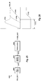
- FIG. 2A is an overall block diagram of a FRAM memory based passive RFID tag according to the present invention.
- FIG. 2B is a more detailed block diagram of a first portion of the FRAM memory based passive RFID tag referred to in FIG. 2A ;
- FIG. 2C is a more detailed block diagram of a second portion of the FRAM memory based passive RFID tag referred to in FIG. 2B ;
- FIG. 3 is a schematic diagram of the low power voltage regulator and a buffer stage according to the present invention.
- FIG. 4 is a schematic diagram of the low power voltage regulator and an emitter follower stage according to the present invention.
- FIG. 5 is a graph of VDD_REG vs I Load , showing the operation of the low power voltage regulator according to the present invention
- FIG. 6 is a schematic diagram of a transistor identifying voltage and currents used in the graph of FIG. 7 ;
- FIG. 7 is a graph of the sub-threshold operation for a transistor such as the ones used in the low power voltage regulator according to the present invention.
- FIG. 8 is a detailed transistor-level schematic of an embodiment of the low power voltage regulator according to the present invention.
- FIG. 9 is a schematic diagram of a clamping circuit for an RFID tag according to the present invention.
- FIG. 10 is a timing diagram of an overshoot transient in the VDDR power supply for an RFID due to a slow clamping circuit according to the prior art
- FIG. 11 is a timing diagram of the VDDR response to a fast RF rise with both active and dynamic clamping according to the present invention.
- FIG. 12 is a schematic diagram of a power-on sequencing circuit for an RFID tag according to the present invention.
- FIG. 13 is a timing diagram associated with the circuit of FIG. 12 ;
- FIG. 14 is a schematic diagram of a power-on reset circuit according to the present invention.
- FIG. 15 is a timing diagram associated with the circuit of FIG. 14 ;
- FIG. 16 is a block diagram of a state machine according to the present invention.
- FIG. 17 is a timing diagram associated with the state machine of FIG. 16 ;
- FIG. 18 is a timing diagram associated with the power-on reset circuit of FIG. 14 ;
- FIG. 19 is a schematic diagram of a first delay circuit embodiment for use with a power supply of an RFID tag according to the present invention.
- FIG. 20 is a timing diagram associated with the delay circuit of FIG. 19 ;
- FIG. 21 is a schematic diagram of a second delay circuit embodiment for use with a power supply of an RFID tag according to the present invention.
- FIG. 22 is a timing diagram associated with the delay circuit of FIG. 21 ;
- FIG. 23 is a schematic diagram of a third delay circuit embodiment for use with a power supply of an RFID tag according to the present invention.
- FIG. 24 is a timing diagram associated with the delay circuit of FIG. 23 ;
- FIG. 25 is a schematic diagram of a cascaded delay circuit embodiment according to the present invention.
- FIG. 26 is a timing diagram associated with the cascaded delay circuit of FIG. 26 ;
- FIG. 27 is a schematic diagram of a bandgap ready circuit according to the present invention.
- FIG. 28 is a schematic diagram of a logic circuit for use with the bandgap ready circuit of FIG. 27 ;
- FIG. 29 is a timing diagram associated with the bandgap ready circuit of the present invention.
- FIG. 30 is a schematic diagram of a prior art demodulation circuit.
- FIG. 31 is a timing diagram associated with the prior art demodulation circuit of FIG. 30 ;
- FIG. 32 is a timing diagram associated with the prior art demodulation circuit of FIG. 30 ;
- FIG. 33 is a schematic diagram of a dynamic adjusting RFID demodulation circuit according to the present invention.
- FIGS. 34-36 are timing diagrams associated with the dynamic adjusting RFID demodulation circuit according to the present invention.
- FIGS. 37A and 37B are schematic diagrams of a prior art shunt regulator
- FIG. 38 is a schematic diagram of a shunt regulator driven from a rectifier circuit output having a split output according to the present invention.
- FIGS. 39 and 40 are timing diagrams associated with the shunt regulator of FIG. 38 .
- a passive RFID tag 200 includes an antenna 202 , an analog front end 204 , and a digital portion 206 that includes digital control circuitry and FRAM memory and communicates with the analog front end 204 using the RX and TX paths.
- a more detailed block diagram of a first portion 208 of the RFID tag 200 includes a rectifier 210 , a split output 212 including two diodes described in further detail below, an active clamp 214 , and a dynamic clamp 218 coupled to the VDDR power supply, which is also described in further detail below.
- the rectifier output is also coupled to a demodulator 216 for providing a digital output, which is also described in further detail below.
- a more detailed block diagram of a second portion 220 of the RFID tag 200 includes a slew filter 224 and a bandgap circuit 222 both coupled to the VDDR power supply, and both described in further detail below.
- the output of the slew filter is coupled to a VDDM regulator 226 for providing a VDDM supply voltage.
- a VDDD regulator 228 is coupled to the VDDM supply voltage, as well as delay circuits 232 and 234 .
- a VDDMPOK circuit 238 receives the VDDM, VBG, and DLY 2 signals and provides a VDDMPOK signal.
- a delay circuit 240 receives the VDDMPOK signal and provides a GEN 2 POK signal.
- a reset circuit 242 receives the GEN 2 POK and VDDMPOK signals to provide a RESET signal.
- circuit 236 receives the VDDMPOK, GEN 2 POK, and PORBTHRESH signals to provide a VDDD_PORB signal. The nature of all of these further signals and circuits is explained in further detail below.
- Circuit 230 monitors the VDDD threshold.
- a low power voltage regulator 300 includes an output node for providing a regulated output voltage (VDD_REG), a first diode-connected transistor Q 1 of a first polarity type (P-channel) in series with a second diode-connected transistor Q 2 of a second polarity type (N-channel) coupled between the output node and ground.
- a bias current I BIAS has a value for biasing the first and second diode-connected transistors in a sub-threshold mode of operation as is explained in further detail below.
- the I BIAS current can be generated using a bandgap circuit or other bias current circuits as are known in the art.
- a buffer amplifier 302 is coupled to the output node to provide a low impedance regulated output voltage.
- a low power voltage regulator 400 includes an output node for providing a regulated output voltage (VDD_REG), and a first diode-connected transistor Q 1 of a first polarity type (P-channel) in series with a second diode-connected transistor Q 2 of a second polarity type (N-channel) coupled between the output node and ground.
- a diode D 3 is provided to compensate for the voltage drop seen in Q 3 to the regulated voltage VDD_REG.
- a bias current I BIAS has a value for biasing the first and second diode-connected transistors in a sub-threshold mode (or other mode) of operation as is explained in further detail below, as well as diode D 3 .
- An emitter follower stage transistor Q 3 is coupled to the output node (through diode D 3 ) to provide a low impedance regulated output voltage.
- the circuit of FIG. 4 is not a constant voltage generator. At lower temperatures a higher total voltage V 2 results given a constant bias current. At higher temperatures a lower total voltage V 1 results given the same constant bias current. Thus, the total voltage decreases with increased temperature change.
- the voltage VDD_REG is a temperature compensated voltage, which helps to provide stable circuit performance. A higher VDD_REG voltage is provided to compensate for relatively slower transistors, which occurs at lower temperatures. A lower VDD_REG voltage is provided to compensate for relatively faster transistors, which occurs at higher temperatures.
- the level of I BIAS also sets the operating mode of Q 1 and Q 2 as sub-threshold or higher power mode.
- a transistor is shown identifying the drain-source current (IDS), drain-source voltage (V DS ), and the gate-source voltage (V Gs ) thereof.
- FIG. 7 a graph is shown plotting the drain-source current of a transistor in response to the gate-source voltage.
- a threshold voltage V THRESHOLD is shown. Above the threshold voltage, the transistor operates in the “Square Law” mode of operation. Below the threshold voltage, the transistor operates in an exponential mode of operation, with the leakage current of the device forming a current floor level.
- the bias current through transistors Q 1 and Q 2 , as well as serially connected diode D 3 is constrained to operate those transistors in the sub-threshold mode of operation for very low power operation. This insures that the circuit of FIG. 4 operates a low power mode, which is of critical importance in an RFID tag, as the available energy for circuit operation is extremely limited. With larger I BIAS a higher power, higher performance circuit operation is obtained.
- Low power voltage regulator 800 includes a first diode-connected transistor Q 1 of a first polarity type (P-channel) in series with a second diode-connected transistor Q 2 of a second polarity type (N-channel) coupled between the output node and ground.
- a bias current generator I 1 is used to bias the first and second diode-connected transistors in a sub-threshold mode of operation.
- a third diode-connected transistor (Q 3 , N-channel) is coupled between the bias current I 1 and the first and second diode-connected transistors Q 1 and Q 2 .
- a buffer amplifier (Q 4 , Q 5 , I 2 , I 3 ) is coupled to the third transistor Q 3 for providing a regulated output voltage VDD_REG.
- the buffer amplifier includes an input transistor Q 4 (N-channel) having its gate forming the input of the buffer, and its source forming the output of the buffer for providing the regulated output voltage.
- a feedback transistor Q 5 (P-channel) is also included having a gate coupled to the drain of the input transistor, a source for coupling to a power supply voltage, and a drain coupled to the source of the input transistor Q 4 .
- a first buffer bias current I 2 is coupled to the drain of the input transistor Q 4 and a second buffer bias current I 3 is coupled to the source of the input transistor Q 4 .
- the value of the second bias current I 3 is greater than the value of the first bias current I 2 .
- Representative values of the bias currents for the voltage regulator 800 in very low power operation are as follows: I 1 is 20 nA, I 2 is 20 nA, and I 3 is 40 nA.
- a clamp circuit 900 for an RFID tag is shown in FIG. 9 including a VDDR power supply node (clamped power supply voltage provided by the RFID rectifier circuit, not shown in FIG. 9 ), a dynamic clamp 902 coupled between the power supply node and ground, and an active clamp 904 also coupled between the power supply and ground, holding the power supply VDDR at a maximum steady state clamped value when the RF supplied power exceeds an operating minimum.
- VDDR power supply node clampped power supply voltage provided by the RFID rectifier circuit, not shown in FIG. 9
- an active clamp 904 also coupled between the power supply and ground, holding the power supply VDDR at a maximum steady state clamped value when the RF supplied power exceeds an operating minimum.
- the dynamic clamp 900 includes a capacitor divider circuit including capacitors C 91 and C 92 coupled between the VDDR rail and ground.
- a resistor R 91 is coupled to the capacitor divider circuit at center tap node 906 .
- An N-channel transistor Q 91 has a gate coupled to the capacitor divider circuit at center tap node 906 .
- the drain of transistor Q 91 is coupled to the VDDR rail and the source is coupled to ground.
- the active clamp includes a differential amplifier 906 having a first input coupled to a resistor divider including resistors R 92 and R 93 at center tap node 908 , a second input for receiving a reference voltage VREF, and an output coupled to a P-channel transistor Q 92 for providing the clamped VDDR voltage.
- the differential amplifier 906 can be an operational amplifier.
- the gate of transistor Q 92 is coupled to the output of differential amplifier 906 , the clamped VDDR voltage is provided at a source of the transistor, and the drain of the transistor is tied to ground.
- a holding capacitor C 93 is attached between VDDR and ground.
- the clamped VDDR is also referred to as ‘VDD’ in the following section.
- the overshoot transient in the VDD clamped supply voltage is shown due to the undesirably slow response of a prior art clamping circuit.
- the power supply voltage waveform 1002 attains a desirably final VDD voltage level only after experiencing a significant overshoot that may adversely affect downstream circuitry.
- the prior art VDD voltage waveform 1102 including the undesirable overshoot is shown along with the VDD voltage waveform 1104 clamped with the active and dynamic clamping according to the present invention. Note that the voltage waveform 1104 has a much reduced overshoot.
- a clamping method for an RFID tag includes providing a power supply voltage from an RFID rectifier having an overshoot in an unclamped condition, and clipping excess energy harvested by the RFID rectifier during an overshoot time period to prevent the overshoot and to prevent overdriving subsequent RFID circuitry.
- This method is provided by using a dynamic clamp in cascade with an active clamp.
- the dynamic clamp includes an NMOS transistor for shunting fast rising initial energy from the RFID rectifier output, and further includes a leakage path for turning off the NMOS transistor after the overshoot time period.
- a clamping method for an RFID tag includes removing energy harvested by an RFID rectifier from a fast rising RF field that would generate an overshoot condition for a predetermined initial time period to prevent overshoot and to prevent overdriving subsequent RFID circuitry.
- circuit 1200 provides sequencing control for an RFID tag according to the present invention.
- the voltage at input node ( 1 ) is the raw power supply voltage VDDR supplied by the dynamically and actively clamped output of the rectifier, Power VDDR in FIG. 2B .
- the circuit 1200 can be realized in a one-chip or two-chip solution.
- Circuit block 1202 is a normal bandgap circuit, coupled to the bandgap ready circuit 1204 at node ( 2 ). Bandgap ready circuit 1204 is explained in further detail below.
- Circuit block 1206 is a slew filter that is explained in further detail below. The output of the slew filter is shown as node ( 3 ), coupled to filter capacitor 1208 .
- Circuit block 1210 is an LDO regulator generating power for the memory circuit block 1224 , for the digital voltage regulator circuit block 1212 . It also provides a divided down signal to circuit block 1214 , a comparator, where it is compared to the bandgap voltage to generate signal VDDMPOK explained further below.
- the “memory VDDM” voltage means the VDD voltage provided to the memory.
- Note FRAM memory block 1224 is coupled to the VDDM line.
- Circuit block 1212 is a second regulator for providing the regulated VDDD voltage to the digital circuitry on the chip designated by block 1226 at node ( 5 ).
- Circuit block 1214 is a comparator. Three inputs are shown, which include a positive input, a negative input, and an enable input.
- the outputs of comparator 1214 are VDDMPOK, and the inverted VDDMPOK signals.
- the VDDMPOK signal node is labeled ( 6 A).
- the VDDMPOK signal designation means “VDDM Power is OK”.
- Blocks 1216 and 1218 are delay circuits that are explained in further detail below.
- Circuit block 1220 is also a delay circuit. Delay circuit 1220 can be a simple analog delay using a current source and a capacitor, and is used to generate the GEN 2 POK signal at node ( 6 B) as shown.
- Block 1222 is a voltage monitor, and is described in further detail below.
- a reset signal generating block 1228 is shown for generating a reset signal at node 1808 .
- FIG. 13 is a timing diagram associated with FIG. 12 , wherein the node waveforms for nodes ( 1 ), ( 2 ), ( 3 ), ( 4 ), and ( 5 ) are shown.
- the corresponding waveforms are designated 1302 , 1304 , 1306 , 1308 , and 1310 .
- One of the most important functions associated with the circuit of FIG. 12 is to protect the FRAM memory from any loss of contents by shutting down the memory properly. That is, a new memory access is prevented when the memory voltage is below a certain value. Memory operation is only possible when VDDM is above a first threshold value, and maintains that value. Memory operation is discontinued when VDDM drops below a second threshold value.
- a voltage monitor circuit including a transistor Q 1402 , a capacitor 1404 , and a digital circuit including inverters 1406 and 1408 , and an OR gate 1410 for generating a POR signal.
- a waveform 1502 is shown that is associated with the monitor circuit of FIG. 14 .
- State machine 1600 receives all of the various timing inputs and generates the VDDD_PORB signal. State machine 1600 operates according to the follow rules:
- FIG. 17 a timing diagram is shown associated with the state machine of FIG. 16 .
- the fall edge delay with respect to the VDDMPOK signal 1702 , and the GEN 2 POK signal 1704 is shown, which is in the range of about 2 to 6 microseconds.
- FIG. 18 a timing diagram associated with the overall sequencing circuit of FIG. 12 is shown including the input VDDRAW voltage, the VDDMPOK signal 1804 , the GEN 2 POK signal 1806 , and the discharge pulse 1808 .
- a first delay circuit 1900 for use with a power supply in an RFID tag includes a power supply input VDD_IN and a power supply output VDD_OUT.
- a passive circuit 1902 , 1904 is coupled between the power supply input VDD_IN and ground.
- a transistor Q 1906 has a current path coupled between the power supply input VDD_IN and the power supply output VDD_OUT, and a control node coupled to an intermediate node 1908 of the passive circuit.
- the passive circuit includes a capacitor 1902 and a resistor 1904 in series connection.
- the capacitor 1902 is coupled between the power supply input VDD_IN and the intermediate node 1908 .
- the resistor 1904 is coupled between the intermediate node 1908 and ground.
- Transistor Q 1906 is a P-channel transistor.
- the VDD_IN typically supplied by a diode rectifier on the RFID tag and has an overshoot indicated by waveform 2002 .
- the VDD_OUT waveform 2004 after being processed by first delay circuit 1900 has no overshoot, and is delayed by a predetermined delay time period determined by the time constant of the passive circuit including capacitor 1902 , resistor 1904 .
- a second delay circuit 2100 for use with a power supply in an RFID tag includes a power supply input VDD_IN and a power supply output VDD_OUT.
- a ramp circuit 2102 , 2104 is coupled between the power supply input VDD_IN and ground.
- a transistor Q 2106 has a current path coupled between the power supply input VDD_IN and the power supply output VDD_OUT, and a control node coupled to an intermediate node 2108 of the ramp circuit.
- the ramp circuit includes a capacitor 2102 and a current source 2104 in series connection.
- the current source can be a temperature stabilized current source provided from a bandgap circuit if desired.
- the capacitor 2102 is coupled between the power supply input VDD_IN and the intermediate node 2108 .
- the current source 2104 is coupled between the intermediate node 2108 and ground.
- Transistor Q 2106 is a P-channel transistor.
- the VDD_IN typically supplied by a diode rectifier on the RFID tag and has an overshoot indicated by waveform 2202 .
- the VDD_OUT waveform 2204 after being processed by second delay circuit 2100 has no overshoot, and is delayed by a predetermined delay time period determined by the ramping speed of the ramp circuit including capacitor 1902 , resistor 1904 .
- the predetermined delay time includes a first delay time DLY 1 , which is determined by the current source turning on and a second delay time DLY 2 , which is determined by transistor Q 2106 turning on.
- the bandgap waveform 2206 is also shown in FIG. 22 .
- a third delay circuit 2300 for use with a power supply in an RFID tag includes a power supply input VDD_IN and a power supply output VDD_OUT.
- a current mirror circuit Q 2302 , Q 2304 has an input coupled to a current source 2306 , an output coupled to the power supply output VDD_OUT, and a power node coupled to the power supply input VDD_IN.
- a capacitor 2308 (C LARGE ) is coupled between the power supply output VDD_OUT and ground.
- the current mirror circuit comprises a simple two-transistor current mirror with a P-channel MOS input transistor Q 2302 and a P-channel MOS mirror transistor Q 2304 . Other more complicated current mirror circuits as are known in the art can also be used.
- Current source 2306 can be a temperature stabilized current source from bandgap circuit if desired.
- the VDD_IN typically supplied by a diode rectifier on the RFID tag and has an overshoot indicated by waveform 2402 .
- the VDD_OUT waveform 2404 after being processed by first delay circuit 1900 has no overshoot, and is delayed by a predetermined delay time period determined by I REF turning on.
- the slew rate of the output waveform 2404 is defined by the values of the current source 2306 and the capacitor 2308 until a stable final output voltage value is reached.
- a cascaded delay circuit providing power to a regulator 2600 for an RFID tag is shown in FIG. 25 including a power supply input VDD_IN and a power supply output VDD_OUT and two delay circuits 2602 , 2604 in cascade connection between the power supply input and the power supply output.
- delay cell 2602 can be the delay cell 1900 shown in FIG. 19 or the delay cell 2100 shown in FIG. 21 .
- the delay cell 2604 can be the slew filter 2300 shown in FIG. 23 .
- the regulator 2606 can be any known voltage regulator such as an LDO, shunt, or source follower regulator.
- Delay cell 2602 can comprise delay circuit 1900 or delay circuit 2100 as discussed above coupled between a local power supply input (VDD_IN) and a local power supply output 2610 .
- Slew filter 2604 can comprise delay circuit 2300 as discussed above coupled between a local power supply input 2610 and a local power supply output 2612 .
- Voltage regulator 2606 can comprise any known voltage regulator as discussed above coupled between a local power supply input 2612 and a local power supply output VDD_OUT.
- the VDD_IN waveform 2702 is shown having an overshoot.
- the output of the first delay cell 2706 is shown slightly delayed and having no overshoot.
- the output of the slew filter 2704 is shown still further delayed and having a slew-controlled output up to a final stable voltage output. This output is still further delayed and regulated by the voltage regulator as shown in waveform 2708 .
- the total delay 2710 is shown between the onset of the VDD_IN waveform and the start of the VDD_OUT regulated output voltage.
- the purpose of the various single and cascaded power supply delay circuits is to provide a control mechanism for turning on circuit blocks and functions inside of an RFID tag only when it can be assured that a stable power supply voltage can be provided. It will be apparent to those skilled in the art that the cascaded delay circuit 2600 can be designed with other arrangements of delay cells while still providing the desirable stable voltage function.
- a circuit for detecting the safe voltage operation for a chip such as found in an RFID tag it is necessary to first detect when the system reference level, derived from a bandgap voltage generator, is sufficiently stable so that signals generated from this reference will be in a range near steady state operation.
- a regulator that has a bandgap reference generates a voltage proportional to the reference. If the reference is not fully settled, the regulator output is not in its design range.
- the bandgap circuit operates by feedback control to maintain operation at a crossing point of two node voltages, nodes 1 and 2 .
- a third branch that crosses one of the nodes during the turn-on transient and is at a higher steady state voltage, at a lower than final operational voltage is used to generate a voltage that is compared with one of the bandgap reference voltages, node 1 , to create part of a bandgap ready logic signal.
- the branch transients are not well controlled and an erroneous valid operation was predicted.
- an additional monitoring circuit was added to detect saturation operation of the core branch of currents in the bandgap voltage generator that would be combined with the crossing information logic signal to more reliably predict when the bandgap reference cell was close to steady state operation. Once the band gap reference cell is at steady state operation valid comparisons of regulator outputs for signaling to control circuits that the proper state of the power supply has been reached.
- Bandgap circuits are well known in the art. It is also well known that voltage regulation such as is required in a chip in an RFID tag requires a stable bandgap reference voltage. During power up, monitor circuits used in the power-up sequence will undesirably glitch if the reference is not yet stable and may improperly release circuit functions when supplies are out of operational range. Prior art uses timing delays to allow the bandgap reference circuit to settle before indicating that a stable operating voltage has been reached. While the approach according to the present invention is effective for assuring that a proper operating voltage has been reached, and then other circuit function can begin, it is process sensitive and should be tuned to ensure optimum performance.
- a ‘bandgap ready’ circuit 2800 includes a bandgap circuit for providing a bandgap voltage including diodes D 2820 , D 2822 , resistor R 1 designated 2832 , N-channel transistors Q 2810 and Q 2812 , and P-channel transistors Q 2804 and Q 2806 .
- Transistors Q 2810 and Q 2812 form an N-channel current mirror.
- Transistors Q 2804 and Q 2806 form a P-channel current mirror.
- Other bandgap designs would have equivalent monitoring nodes from this example design.
- P-channel transistor Q 2808 is mirrored from the P-channel current mirror.
- the drain current from transistor Q 2808 is used to generate the V BGAP voltage across diode resistor R 2 designated 2834 and diode D 2824 .
- a capacitor C 2826 is coupled to the bandgap output voltage node.
- a first comparator 2828 is used for monitoring first and second voltages in the bandgap circuit and for providing a first logic signal at node 2814 .
- a first input is coupled to the source of transistor Q 2810 and a second input is coupled to the drain of P-channel transistor Q 2802 in a replica branch. The current through transistor Q 2802 generates a slightly larger and tracking voltage to node 2 in the bandgap core, across resistor R 3 designated 2830 and diode D 2818 .
- a second comparator 2826 is used for monitoring third and fourth voltages in the bandgap circuit and for providing a second logic signal at node 2816 .
- a first input is coupled to the drain of transistor Q 2806 and a second input is coupled to the drain of transistor Q 2808 , which is also coupled to resistor R 2830 , as shown.
- an AND logic circuit 2900 for combining the first and second logic signals at nodes 2814 and 2816 is used to provide a bandgap ready logic signal BGOK.
- FIG. 29( a ) a graph of the voltages at the source of transistor Q 2810 and drain of transistor Q 2802 are shown, designated nodes ( 1 ) and ( 3006 ) in FIG. 27 .
- the crossover point of these two voltages is used to generate the first logic signal at node 2814 .
- the comparison is not done directly on core nodes, but rather through the replica branch provided by transistor Q 2802 , resistor R 3 designated 2830 , and diode D 2818 as discussed above.
- the VDD supply voltage is shown crossing a minimum allowable operational threshold with respect to time.
- Waveform 3002 represents the voltage at node ( 3 )
- waveform 3004 represents the voltage at node ( 1 )
- waveform 3006 represents the voltage at the top of resistor R 3 at node ( 2 )
- voltage difference 3008 represents a guaranteed crossing voltage difference due to steady state core current I multiplied by R 3 .
- a prior art demodulation circuit 3100 including an RF input at node 3114 , an input diode 3102 coupled between input node 3114 and node 3116 .
- a resistor 3104 in parallel with capacitor 3106 is coupled to node 3116 .
- Diode 3102 , resistor 3104 , and capacitor 3106 form an envelope detector as is known in the art.
- the signal at node 3116 is filtered by a low pass filter including resistor 3108 and capacitor 3110 .
- the output of the low pass filter at node 3118 , and the envelope signal at node 3116 are received by a comparator 3112 to provide a data output digital signal at output node 3120 .
- FIG. 31 a timing diagram is shown including the RF waveform 3114 and the envelope waveform 3116 .
- the timing diagram of FIG. 32 shows the envelope waveform 3116 , as well as the output waveform showing the desirable average value and the undesirable ripple that is produced due to the averaging circuit 3100 .
- Prior art RFID demodulation circuits such as those described above may not provide proper operation over all input power levels due to large input signals at high power.
- Averaging schemes to correct this problem are problematic because they are data rate dependent, leading to a variation in pulse widths during the averaging transient.
- a fixed reference was added where the power level reduction in operating margin was detected.
- An additional signal dependent current was added to the reference voltage so that higher power levels generated their own higher level reference as is explained in further detail below.
- Transient pulse width changes with averaging circuits corrupt data detection.
- a single filter time constant is not sufficient for both low and high data rates.
- the ripple signal on the average is low, but there is a long transient during which the duty cycle changes.
- the ripple signal is large and can cross the detection threshold depending on input power level. Both of these extremes can see errors in data detection during startup conditions.
- Dynamic adjusting RFID demodulator circuit 3400 includes an envelope detector 3402 , 3404 , 3406 having an input for receiving a modulated RF signal at node 3422 , a fixed reference 3412 , Q 3414 coupled to the input of an RC filter 3416 , 3418 and a comparator 3420 having a first input coupled to the output of the envelope detector, a second input coupled to an output of the RC filter, and an output for providing a data output signal at node 3430 .
- the envelope detector includes an input diode 3402 , parallel resistor 3404 and capacitor 3406 , as well as an output diode 3408 and an output resistor 3410 .
- the fixed reference includes a current source 3412 , which can be a thermally compensated current source derived from a bandgap circuit, and a diode-connected N-channel transistor Q 3414 . Other fixed references can be used.
- the RC filter includes a resistor 3416 and a capacitor 3418 .
- the first input of the comparator 3424 is a positive input and the second input is a negative input in a preferred embodiment.
- Demodulator circuit 3400 of the present invention thus includes a fixed reference generated by a current source (from a bandgap circuit if desired) and a diode-connected MOS transistor and an RC filter plus another energy path activated at higher power levels that inject current into the output of the RC filter at the input to the comparator.
- the threshold of the comparator is thus augmented proportionally to the input power so that high power and low power RF input signals are equally discriminated.
- FIGS. 34-36 various circuit waveforms are shown that illustrate the dynamic threshold of circuit 3400 responding to different input levels.
- a first RF envelope 3424 A is shown at low power levels.
- a second RF envelope 3424 B is shown at relatively higher power levels.
- the threshold voltage for comparator 3420 at low power levels is the same at both nodes 3426 and 3428 .
- the voltage levels at nodes 3426 and 3428 are different at higher power levels. That is, the voltage at node 3428 is greater than that at node 3426 at higher power levels.
- FIG. 36 the voltage at node 3428 is shown with respect to increasing RF input power levels. The voltage at node 3428 begins at a first level and increases as the input power is increased.
- a rectifier 3802 receives an RF input signal, which is rectified to provide a supply voltage, which is the same voltage node that is regulated, V REG , as is known for a shunt regulator.
- a resistor divider circuit and comparator 3804 are coupled between V REG and ground. The resistor divider circuit and comparator receive an input reference voltage and provide a control voltage at node 3812 for a discharge device.
- a P-channel discharge device shown here for example, transistor Q 3806 has a source coupled to the V REG node, a gate for receiving the control voltage at node 3812 , and a drain coupled to ground.
- the V REG is coupled to a large holding capacitor 3808 , which provides a stable voltage and energy for powering on-chip circuits such as a FRAM memory circuit, various digital and analog circuits, and I/O circuits.
- the resistor divider circuit and comparator 3804 are shown in further detail in FIG. 37B , wherein a resistor divider including resistors 3814 and 3816 is coupled between the V REG and ground.
- An amplifier 3818 receives the input reference voltage at a first input (negative) and a tap voltage of the resistor divider at a second input (positive). The output voltage of the amplifier 3818 provides the control voltage for the P-channel transistor Q 3806 at node 3812 as shown.
- the holding capacitor 3808 is effectively the on-chip power supply voltage for the rest of the integrated circuit, or circuits in an RFID tag.
- the voltage on the capacitor 3808 is from charge harvested from an RF reader. It is important that this charge be conserved and not wasted during any regulation operations.
- a shunt regulator 3900 for an RFID tag chip having a split source output from the RF rectifier including a first output 3914 for providing a power delivery path to on-chip circuits 3916 and a second output 3924 for providing a discharge-regulation path.
- the on-chip circuits can include a FRAM memory circuit, I/O circuits, and other digital and analog circuitry as required for a specific application.
- a large holding capacitor 3912 is coupled between the first output 3914 and ground.
- the shunt regulator 3900 includes an input node 3902 for receiving a power supply voltage from a rectifier output, a first diode 3904 having an anode coupled to the input node, a second diode 3906 having an anode coupled to the input node, a resistor divider circuit and comparator 3908 coupled between a cathode of the first diode and ground, a P-channel transistor 3910 having a control terminal coupled to an output of the resistor divider circuit and comparator at node 3918 , and a current path coupled between a cathode of the second diode and ground, wherein the cathode of the first diode forms the first output 3914 and the cathode of the second diode forms the second output 3924 .
- the resistor divider and comparator circuit 3908 are substantially the same as is shown in FIG. 37B .
- FIG. 39 a plot 4000 is shown of the unregulated voltage waveform 4002 and the regulated voltage waveform 4004 with respect to ground.
- the input unregulated voltage 4002 which exceeds a desirable upper value, is shown to be regulated to a constant acceptable upper value in the regulated voltage 4004 .
- current ICONTROL shown in FIG. 38 pulls down node 3902 , isolating node 3914 in the presence of excess RF energy.
- the input voltage from the rectifier at node 3902 is plotted in juxtaposition with the output voltage at the first output node 3914 with the shunt regulator crossing into regulation.
- An overvoltage condition results in activation of Q 3910 in FIG. 39 dumping excess harvested energy and pulling down node 3902 and isolating 3914 and not discharging capacitor 3912 .
- the input voltage also drops; however, the on-chip power supply voltage at node 3914 remains high momentarily, and the extra charge is conserved and can be continued to be used for powering on-chip circuits.
- the separation of the discharge-regulation path from the power delivery path regulation can be maintained while not removing the charge from the hold capacitor 3912 that powers the rest of the circuitry. Separating the outputs according to the present invention as described makes the RFID tag more efficient.
Abstract
Description
Claims (20)
Priority Applications (1)
| Application Number | Priority Date | Filing Date | Title |
|---|---|---|---|
| US13/490,285 US8729960B2 (en) | 2011-06-10 | 2012-06-06 | Dynamic adjusting RFID demodulation circuit |
Applications Claiming Priority (2)
| Application Number | Priority Date | Filing Date | Title |
|---|---|---|---|
| US201161495700P | 2011-06-10 | 2011-06-10 | |
| US13/490,285 US8729960B2 (en) | 2011-06-10 | 2012-06-06 | Dynamic adjusting RFID demodulation circuit |
Publications (2)
| Publication Number | Publication Date |
|---|---|
| US20120313698A1 US20120313698A1 (en) | 2012-12-13 |
| US8729960B2 true US8729960B2 (en) | 2014-05-20 |
Family
ID=47292672
Family Applications (1)
| Application Number | Title | Priority Date | Filing Date |
|---|---|---|---|
| US13/490,285 Active 2032-07-25 US8729960B2 (en) | 2011-06-10 | 2012-06-06 | Dynamic adjusting RFID demodulation circuit |
Country Status (1)
| Country | Link |
|---|---|
| US (1) | US8729960B2 (en) |
Cited By (4)
| Publication number | Priority date | Publication date | Assignee | Title |
|---|---|---|---|---|
| US20130278060A1 (en) * | 2012-04-20 | 2013-10-24 | Hon Hai Precision Industry Co., Ltd. | Minimum output current adapting circuit and motherboard using same |
| US9515702B2 (en) | 2014-11-12 | 2016-12-06 | Samsung Electronics Co., Ltd. | Demodulators for near field communication, near field communication devices, and electronic devices having the same |
| US11481595B2 (en) | 2020-12-18 | 2022-10-25 | Nxp B.V. | Dual system RFID tag |
| US11748590B2 (en) | 2020-12-18 | 2023-09-05 | Nxp B.V. | RFID tag with impedance tuning,and method of impedance tuning of an RRID tag |
Families Citing this family (16)
| Publication number | Priority date | Publication date | Assignee | Title |
|---|---|---|---|---|
| KR101844300B1 (en) * | 2012-01-26 | 2018-05-15 | 삼성전자주식회사 | Dynamically controlled envelope detection apparatus in response to input signal and method enabling the apparatus |
| US10698432B2 (en) * | 2013-03-13 | 2020-06-30 | Intel Corporation | Dual loop digital low drop regulator and current sharing control apparatus for distributable voltage regulators |
| US9680520B2 (en) | 2013-03-22 | 2017-06-13 | University Of Washington Through Its Center For Commercialization | Ambient backscatter tranceivers, apparatuses, systems, and methods for communicating using backscatter of ambient RF signals |
| DE102013114137A1 (en) * | 2013-12-16 | 2015-06-18 | Endress + Hauser Conducta Gesellschaft für Mess- und Regeltechnik mbH + Co. KG | Electronic circuit and method for demodulating a carrier signal |
| WO2015123306A1 (en) | 2014-02-11 | 2015-08-20 | University Of Washington | Apparatuses, systems, and methods for communicating using mimo and spread spectrum coding in backscatter of ambient signals |
| US10382161B2 (en) | 2014-02-11 | 2019-08-13 | University Of Washington | Wireless networking communication methods, systems, and devices operable using harvested power |
| US9590504B2 (en) * | 2014-09-30 | 2017-03-07 | Taiwan Semiconductor Manufacturing Company, Ltd. | Flipped gate current reference and method of using |
| US10079616B2 (en) | 2014-12-19 | 2018-09-18 | University Of Washington | Devices and methods for backscatter communication using one or more wireless communication protocols including bluetooth low energy examples |
| WO2017027847A1 (en) | 2015-08-12 | 2017-02-16 | University Of Washington | Backscatter devices and network systems incorporating backscatter devices |
| WO2017132400A1 (en) | 2016-01-26 | 2017-08-03 | University Of Washington | Backscatter devices including examples of single sideband operation |
| CN109073573A (en) | 2016-04-04 | 2018-12-21 | 华盛顿大学 | The backscatter device and system through back-scattered signal comprising OFDM packet is provided |
| US10812130B2 (en) | 2016-10-18 | 2020-10-20 | University Of Washington | Backscatter systems, devices, and techniques utilizing CSS modulation and/or higher order harmonic cancellation |
| US9762282B1 (en) * | 2017-03-15 | 2017-09-12 | Texas Instruments Deutschland Gmbh | Integrated circuits and transponder circuitry with improved ask demodulation |
| US10461783B2 (en) | 2017-03-16 | 2019-10-29 | University Of Washington | Radio frequency communication devices having backscatter and non-backscatter communication modes and hardware re-use |
| CN110663020A (en) | 2017-04-06 | 2020-01-07 | 华盛顿大学 | Image and/or video transmission using a backscatter device |
| DE102019111500B4 (en) * | 2019-05-03 | 2022-11-10 | ASTRA Gesellschaft für Asset Management mbH & Co. KG | UHF reader |
Citations (50)
| Publication number | Priority date | Publication date | Assignee | Title |
|---|---|---|---|---|
| US4128816A (en) | 1976-07-16 | 1978-12-05 | Kabushiki Kaisha Daini Seikosha | Electronic circuit |
| US4217540A (en) | 1977-06-27 | 1980-08-12 | Kabushiki Kaisha Daini Seikosha | Voltage regulated electronic timepiece |
| US4250464A (en) | 1978-07-03 | 1981-02-10 | Rca Corporation | Multi-mode relaxation oscillator |
| US4300061A (en) | 1979-03-15 | 1981-11-10 | National Semiconductor Corporation | CMOS Voltage regulator circuit |
| US4477737A (en) | 1982-07-14 | 1984-10-16 | Motorola, Inc. | Voltage generator circuit having compensation for process and temperature variation |
| US4533970A (en) | 1983-06-27 | 1985-08-06 | Motorola, Inc. | Series current limiter |
| US4644300A (en) | 1983-12-26 | 1987-02-17 | Kabushiki Kaisha Toshiba | Voltage-controlled variable-frequency pulse oscillator |
| US4857823A (en) | 1988-09-22 | 1989-08-15 | Ncr Corporation | Bandgap voltage reference including a process and temperature insensitive start-up circuit and power-down capability |
| US5039934A (en) | 1990-05-22 | 1991-08-13 | Keithley Instruments, Inc. | Control for voltage/current source with current/voltage limiting |
| US5159216A (en) | 1990-10-25 | 1992-10-27 | Triquint Semiconductor, Inc. | Precision tristate output driver circuit having a voltage clamping feature |
| US5187389A (en) | 1991-05-03 | 1993-02-16 | National Semiconductor Corporation | Noise resistant low voltage brownout detector with shut off option |
| US5434534A (en) | 1993-11-29 | 1995-07-18 | Intel Corporation | CMOS voltage reference circuit |
| US5515226A (en) | 1994-01-25 | 1996-05-07 | Sgs-Thomson Microelectronics, S. A. | Integrated circuit incorporating a system of protection against electrostatic discharges |
| US5559451A (en) | 1994-09-08 | 1996-09-24 | Nec Corporation | Bicmos push-pull type logic apparatus with voltage clamp circuit and clamp releasing circuit |
| US5708549A (en) | 1996-10-04 | 1998-01-13 | Harris Corporation | Integrated circuit having enhanced transient voltage protection and associated methods |
| US5796295A (en) | 1995-04-21 | 1998-08-18 | Advanced Micro Devices, Inc. | Reference for CMOS memory cell having PMOS and NMOS transistors with a common floating gate |
| US5870000A (en) | 1996-05-21 | 1999-02-09 | Fujitsu Limited | Oscillation circuit and PLL circuit using same |
| US5945920A (en) | 1997-12-10 | 1999-08-31 | Atmel Corporation | Minimum voltage radio frequency indentification |
| US6208197B1 (en) | 1999-03-04 | 2001-03-27 | Vanguard International Semiconductor Corp. | Internal charge pump voltage limit control |
| US6225664B1 (en) | 1998-04-30 | 2001-05-01 | Kabushiki Kaisha Toshiba | Dielectrically isolated IC driver having upper-side and lower-side arm drivers and power IC having the same |
| US6229290B1 (en) | 2000-05-19 | 2001-05-08 | Silicon Storage Technology, Inc. | Voltage regulating circuit with a clamp up circuit and a clamp down circuit operating in tandem |
| US6281743B1 (en) | 1997-09-10 | 2001-08-28 | Intel Corporation | Low supply voltage sub-bandgap reference circuit |
| US6566850B2 (en) | 2000-12-06 | 2003-05-20 | Intermec Ip Corp. | Low-voltage, low-power bandgap reference circuit with bootstrap current |
| US6625231B1 (en) | 1999-11-15 | 2003-09-23 | Ericsson Inc. | Adaptive phase demodulation |
| US6642757B2 (en) | 2000-09-21 | 2003-11-04 | Kabushiki Kaisha Toshiba | Semiconductor memory device having a power-on reset circuit |
| US6713991B1 (en) | 2002-04-24 | 2004-03-30 | Rantec Power Systems Inc. | Bipolar shunt regulator |
| US6737908B2 (en) | 2002-09-03 | 2004-05-18 | Micrel, Inc. | Bootstrap reference circuit including a shunt bandgap regulator with external start-up current source |
| US6768222B1 (en) | 2000-07-11 | 2004-07-27 | Advanced Micro Devices, Inc. | System and method for delaying power supply power-up |
| US6784705B2 (en) | 2002-04-08 | 2004-08-31 | Oki Electric Industry Co., Ltd. | Power on reset circuit |
| US6794856B2 (en) | 2001-07-09 | 2004-09-21 | Silicon Labs Cp, Inc. | Processor based integrated circuit with a supply voltage monitor using bandgap device without feedback |
| US6858917B1 (en) | 2003-12-05 | 2005-02-22 | National Semiconductor Corporation | Metal oxide semiconductor (MOS) bandgap voltage reference circuit |
| US7116240B2 (en) | 2004-04-13 | 2006-10-03 | Impinj, Inc. | Method and apparatus for controlled persistent ID flag for RFID applications |
| US7116088B2 (en) | 2003-06-09 | 2006-10-03 | Silicon Storage Technology, Inc. | High voltage shunt regulator for flash memory |
| US7133269B2 (en) | 2004-03-04 | 2006-11-07 | Via Technologies, Inc. | Overvoltage protection apparatus |
| US7161338B2 (en) | 2004-11-20 | 2007-01-09 | Hong Fu Jin Precision Industry (Sbenzhen) Co., Ltd. | Linear voltage regulator with an adjustable shunt regulator-subcircuit |
| US20070126584A1 (en) * | 2004-04-13 | 2007-06-07 | Impimj, Inc. | Adaptable Detection Threshold for RFID Tags and Chips |
| US20070210923A1 (en) | 2005-12-09 | 2007-09-13 | Butler Timothy P | Multiple radio frequency network node rfid tag |
| US20070290660A1 (en) | 2005-02-25 | 2007-12-20 | Fujitsu Limited | Shunt regulator and electronic apparatus |
| US20080106416A1 (en) | 2004-09-09 | 2008-05-08 | Sullivan Michael S | RFID tag sensitivity |
| US20080189567A1 (en) | 2006-10-18 | 2008-08-07 | Goodnow Kenneth J | System For Method Of Predicting Power Events In An Intermittent Power Environment And Dispatching Computational Operations Of An Integrated Circuit Accordingly |
| US7436732B2 (en) | 2006-02-07 | 2008-10-14 | Elpida Memory, Inc. | Internal power supply generating circuit without a dead band |
| US7471143B2 (en) | 2006-01-27 | 2008-12-30 | Samsung Electronics Co., Ltd. | Apparatus and method for adaptive demodulation of PWM signal |
| US7554377B1 (en) | 2007-09-17 | 2009-06-30 | National Semiconductor Corporation | Apparatus and method for signal voltage limiting |
| US20090289776A1 (en) | 2006-12-11 | 2009-11-26 | Larry Moore | Composite multiple rfid tag facility |
| US7679412B2 (en) | 2007-09-27 | 2010-03-16 | Kabushiki Kaisha Toshiba | Power supply circuit |
| US7679957B2 (en) | 2005-03-31 | 2010-03-16 | Virage Logic Corporation | Redundant non-volatile memory cell |
| US7710783B2 (en) | 2005-12-08 | 2010-05-04 | Mstar Semiconductor, Inc. | Methods for operating a nonvolatile memory and related circuit |
| US7715236B2 (en) | 2005-03-30 | 2010-05-11 | Virage Logic Corporation | Fault tolerant non volatile memories and methods |
| US7732945B2 (en) | 2004-09-30 | 2010-06-08 | Fujitsu Limited | Rectifier circuit |
| US7876150B2 (en) * | 2008-12-24 | 2011-01-25 | Kabushiki Kaisha Toshiba | ASK demodulator, communication module, communication device, and ASK demodulation method |
-
2012
- 2012-06-06 US US13/490,285 patent/US8729960B2/en active Active
Patent Citations (54)
| Publication number | Priority date | Publication date | Assignee | Title |
|---|---|---|---|---|
| US4128816A (en) | 1976-07-16 | 1978-12-05 | Kabushiki Kaisha Daini Seikosha | Electronic circuit |
| US4217540A (en) | 1977-06-27 | 1980-08-12 | Kabushiki Kaisha Daini Seikosha | Voltage regulated electronic timepiece |
| US4250464A (en) | 1978-07-03 | 1981-02-10 | Rca Corporation | Multi-mode relaxation oscillator |
| US4300061A (en) | 1979-03-15 | 1981-11-10 | National Semiconductor Corporation | CMOS Voltage regulator circuit |
| US4477737A (en) | 1982-07-14 | 1984-10-16 | Motorola, Inc. | Voltage generator circuit having compensation for process and temperature variation |
| US4533970A (en) | 1983-06-27 | 1985-08-06 | Motorola, Inc. | Series current limiter |
| US4644300A (en) | 1983-12-26 | 1987-02-17 | Kabushiki Kaisha Toshiba | Voltage-controlled variable-frequency pulse oscillator |
| US4857823A (en) | 1988-09-22 | 1989-08-15 | Ncr Corporation | Bandgap voltage reference including a process and temperature insensitive start-up circuit and power-down capability |
| US5039934A (en) | 1990-05-22 | 1991-08-13 | Keithley Instruments, Inc. | Control for voltage/current source with current/voltage limiting |
| US5159216A (en) | 1990-10-25 | 1992-10-27 | Triquint Semiconductor, Inc. | Precision tristate output driver circuit having a voltage clamping feature |
| US5187389A (en) | 1991-05-03 | 1993-02-16 | National Semiconductor Corporation | Noise resistant low voltage brownout detector with shut off option |
| US5434534A (en) | 1993-11-29 | 1995-07-18 | Intel Corporation | CMOS voltage reference circuit |
| US5515226A (en) | 1994-01-25 | 1996-05-07 | Sgs-Thomson Microelectronics, S. A. | Integrated circuit incorporating a system of protection against electrostatic discharges |
| US5559451A (en) | 1994-09-08 | 1996-09-24 | Nec Corporation | Bicmos push-pull type logic apparatus with voltage clamp circuit and clamp releasing circuit |
| US5796295A (en) | 1995-04-21 | 1998-08-18 | Advanced Micro Devices, Inc. | Reference for CMOS memory cell having PMOS and NMOS transistors with a common floating gate |
| US5870000A (en) | 1996-05-21 | 1999-02-09 | Fujitsu Limited | Oscillation circuit and PLL circuit using same |
| US5708549A (en) | 1996-10-04 | 1998-01-13 | Harris Corporation | Integrated circuit having enhanced transient voltage protection and associated methods |
| US6281743B1 (en) | 1997-09-10 | 2001-08-28 | Intel Corporation | Low supply voltage sub-bandgap reference circuit |
| US5945920A (en) | 1997-12-10 | 1999-08-31 | Atmel Corporation | Minimum voltage radio frequency indentification |
| US6225664B1 (en) | 1998-04-30 | 2001-05-01 | Kabushiki Kaisha Toshiba | Dielectrically isolated IC driver having upper-side and lower-side arm drivers and power IC having the same |
| US6208197B1 (en) | 1999-03-04 | 2001-03-27 | Vanguard International Semiconductor Corp. | Internal charge pump voltage limit control |
| US6625231B1 (en) | 1999-11-15 | 2003-09-23 | Ericsson Inc. | Adaptive phase demodulation |
| US6229290B1 (en) | 2000-05-19 | 2001-05-08 | Silicon Storage Technology, Inc. | Voltage regulating circuit with a clamp up circuit and a clamp down circuit operating in tandem |
| US6768222B1 (en) | 2000-07-11 | 2004-07-27 | Advanced Micro Devices, Inc. | System and method for delaying power supply power-up |
| US6642757B2 (en) | 2000-09-21 | 2003-11-04 | Kabushiki Kaisha Toshiba | Semiconductor memory device having a power-on reset circuit |
| US6901012B2 (en) | 2000-09-21 | 2005-05-31 | Kabushiki Kaisha Toshiba | Semiconductor memory device having a power-on reset circuit |
| US6566850B2 (en) | 2000-12-06 | 2003-05-20 | Intermec Ip Corp. | Low-voltage, low-power bandgap reference circuit with bootstrap current |
| US7119526B2 (en) | 2001-07-09 | 2006-10-10 | Silicon Labs Cp, Inc. | Processor based integrated circuit with a supply voltage monitor using bandgap device without feedback |
| US6794856B2 (en) | 2001-07-09 | 2004-09-21 | Silicon Labs Cp, Inc. | Processor based integrated circuit with a supply voltage monitor using bandgap device without feedback |
| US6784705B2 (en) | 2002-04-08 | 2004-08-31 | Oki Electric Industry Co., Ltd. | Power on reset circuit |
| US6713991B1 (en) | 2002-04-24 | 2004-03-30 | Rantec Power Systems Inc. | Bipolar shunt regulator |
| US6737908B2 (en) | 2002-09-03 | 2004-05-18 | Micrel, Inc. | Bootstrap reference circuit including a shunt bandgap regulator with external start-up current source |
| US7116088B2 (en) | 2003-06-09 | 2006-10-03 | Silicon Storage Technology, Inc. | High voltage shunt regulator for flash memory |
| US6933770B1 (en) | 2003-12-05 | 2005-08-23 | National Semiconductor Corporation | Metal oxide semiconductor (MOS) bandgap voltage reference circuit |
| US6858917B1 (en) | 2003-12-05 | 2005-02-22 | National Semiconductor Corporation | Metal oxide semiconductor (MOS) bandgap voltage reference circuit |
| US7133269B2 (en) | 2004-03-04 | 2006-11-07 | Via Technologies, Inc. | Overvoltage protection apparatus |
| US20070126584A1 (en) * | 2004-04-13 | 2007-06-07 | Impimj, Inc. | Adaptable Detection Threshold for RFID Tags and Chips |
| US7116240B2 (en) | 2004-04-13 | 2006-10-03 | Impinj, Inc. | Method and apparatus for controlled persistent ID flag for RFID applications |
| US20080106416A1 (en) | 2004-09-09 | 2008-05-08 | Sullivan Michael S | RFID tag sensitivity |
| US7732945B2 (en) | 2004-09-30 | 2010-06-08 | Fujitsu Limited | Rectifier circuit |
| US7161338B2 (en) | 2004-11-20 | 2007-01-09 | Hong Fu Jin Precision Industry (Sbenzhen) Co., Ltd. | Linear voltage regulator with an adjustable shunt regulator-subcircuit |
| US20070290660A1 (en) | 2005-02-25 | 2007-12-20 | Fujitsu Limited | Shunt regulator and electronic apparatus |
| US7715236B2 (en) | 2005-03-30 | 2010-05-11 | Virage Logic Corporation | Fault tolerant non volatile memories and methods |
| US7679957B2 (en) | 2005-03-31 | 2010-03-16 | Virage Logic Corporation | Redundant non-volatile memory cell |
| US7710783B2 (en) | 2005-12-08 | 2010-05-04 | Mstar Semiconductor, Inc. | Methods for operating a nonvolatile memory and related circuit |
| US20080180249A1 (en) | 2005-12-09 | 2008-07-31 | Butler Timothy P | Multiple radio frequency network node rfid tag |
| US20070210923A1 (en) | 2005-12-09 | 2007-09-13 | Butler Timothy P | Multiple radio frequency network node rfid tag |
| US7471143B2 (en) | 2006-01-27 | 2008-12-30 | Samsung Electronics Co., Ltd. | Apparatus and method for adaptive demodulation of PWM signal |
| US7436732B2 (en) | 2006-02-07 | 2008-10-14 | Elpida Memory, Inc. | Internal power supply generating circuit without a dead band |
| US20080189567A1 (en) | 2006-10-18 | 2008-08-07 | Goodnow Kenneth J | System For Method Of Predicting Power Events In An Intermittent Power Environment And Dispatching Computational Operations Of An Integrated Circuit Accordingly |
| US20090289776A1 (en) | 2006-12-11 | 2009-11-26 | Larry Moore | Composite multiple rfid tag facility |
| US7554377B1 (en) | 2007-09-17 | 2009-06-30 | National Semiconductor Corporation | Apparatus and method for signal voltage limiting |
| US7679412B2 (en) | 2007-09-27 | 2010-03-16 | Kabushiki Kaisha Toshiba | Power supply circuit |
| US7876150B2 (en) * | 2008-12-24 | 2011-01-25 | Kabushiki Kaisha Toshiba | ASK demodulator, communication module, communication device, and ASK demodulation method |
Cited By (4)
| Publication number | Priority date | Publication date | Assignee | Title |
|---|---|---|---|---|
| US20130278060A1 (en) * | 2012-04-20 | 2013-10-24 | Hon Hai Precision Industry Co., Ltd. | Minimum output current adapting circuit and motherboard using same |
| US9515702B2 (en) | 2014-11-12 | 2016-12-06 | Samsung Electronics Co., Ltd. | Demodulators for near field communication, near field communication devices, and electronic devices having the same |
| US11481595B2 (en) | 2020-12-18 | 2022-10-25 | Nxp B.V. | Dual system RFID tag |
| US11748590B2 (en) | 2020-12-18 | 2023-09-05 | Nxp B.V. | RFID tag with impedance tuning,and method of impedance tuning of an RRID tag |
Also Published As
| Publication number | Publication date |
|---|---|
| US20120313698A1 (en) | 2012-12-13 |
Similar Documents
| Publication | Publication Date | Title |
|---|---|---|
| US8729960B2 (en) | Dynamic adjusting RFID demodulation circuit | |
| US8841890B2 (en) | Shunt regulator circuit having a split output | |
| US8823267B2 (en) | Bandgap ready circuit | |
| US8729874B2 (en) | Generation of voltage supply for low power digital circuit operation | |
| US8669801B2 (en) | Analog delay cells for the power supply of an RFID tag | |
| US8665007B2 (en) | Dynamic power clamp for RFID power control | |
| US8584959B2 (en) | Power-on sequencing for an RFID tag | |
| US9898631B2 (en) | Intelligent energy management system and energy management method for passive radio frequency tag | |
| US9177182B2 (en) | Semiconductor device for wireless communication | |
| US20080012603A1 (en) | Brown out detector | |
| US8841892B2 (en) | Method and integrated circuit that provides tracking between multiple regulated voltages | |
| US20040136255A1 (en) | Current integrating sense amplifier for memory modules in RFID | |
| US10243410B2 (en) | Electronic device and power management method | |
| US6659352B1 (en) | Semiconductor integrated circuit, a contactless information medium having the semiconductor integrated circuit, and a method of driving the semiconductor integrated circuit | |
| US10432107B2 (en) | Rectifier circuit and electronic device | |
| US10692581B2 (en) | Circuits for bleeding supply voltage from a device in a power down state | |
| US8138764B2 (en) | Test circuit for monitoring a bandgap circuit | |
| US20050277241A1 (en) | Semiconductor device and ic card | |
| US9530088B2 (en) | Radio frequency identification devices | |
| EP3336773B1 (en) | Voltage regulation circuit for an rfid circuit | |
| US7443144B2 (en) | Voltage regulation system comprising operating condition detection means | |
| US20190130237A1 (en) | A radio frequency identification (RFID) tag and a method for limiting supply voltage of a RFID tag | |
| Wang | Power Management Technique Smoothing Regulated Digital Supply Between Modes Switching for Low Power Wireless Sensing Application |
Legal Events
| Date | Code | Title | Description |
|---|---|---|---|
| AS | Assignment |
Owner name: RAMTRON INTERNATIONAL CORPORATION, COLORADO Free format text: ASSIGNMENT OF ASSIGNORS INTEREST;ASSIGNORS:OCHOA, AGUSTIN;PISHDAD, BARDIA;REEL/FRAME:028336/0655 Effective date: 20120531 |
|
| AS | Assignment |
Owner name: CYPRESS SEMICONDUCTOR CORPORATION, CALIFORNIA Free format text: ASSIGNMENT OF ASSIGNORS INTEREST;ASSIGNOR:RAMTRON INTERNATIONAL CORPORATION;REEL/FRAME:029408/0437 Effective date: 20121203 |
|
| STCF | Information on status: patent grant |
Free format text: PATENTED CASE |
|
| AS | Assignment |
Owner name: MORGAN STANLEY SENIOR FUNDING, INC., NEW YORK Free format text: SECURITY INTEREST;ASSIGNORS:CYPRESS SEMICONDUCTOR CORPORATION;SPANSION LLC;REEL/FRAME:035240/0429 Effective date: 20150312 |
|
| MAFP | Maintenance fee payment |
Free format text: PAYMENT OF MAINTENANCE FEE, 4TH YEAR, LARGE ENTITY (ORIGINAL EVENT CODE: M1551) Year of fee payment: 4 |
|
| AS | Assignment |
Owner name: MUFG UNION BANK, N.A., CALIFORNIA Free format text: ASSIGNMENT AND ASSUMPTION OF SECURITY INTEREST IN INTELLECTUAL PROPERTY;ASSIGNOR:MORGAN STANLEY SENIOR FUNDING, INC.;REEL/FRAME:050896/0366 Effective date: 20190731 |
|
| AS | Assignment |
Owner name: MORGAN STANLEY SENIOR FUNDING, INC., NEW YORK Free format text: CORRECTIVE ASSIGNMENT TO CORRECT THE 8647899 PREVIOUSLY RECORDED ON REEL 035240 FRAME 0429. ASSIGNOR(S) HEREBY CONFIRMS THE SECURITY INTERST;ASSIGNORS:CYPRESS SEMICONDUCTOR CORPORATION;SPANSION LLC;REEL/FRAME:058002/0470 Effective date: 20150312 |
|
| MAFP | Maintenance fee payment |
Free format text: PAYMENT OF MAINTENANCE FEE, 8TH YEAR, LARGE ENTITY (ORIGINAL EVENT CODE: M1552); ENTITY STATUS OF PATENT OWNER: LARGE ENTITY Year of fee payment: 8 |
|
| AS | Assignment |
Owner name: SPANSION LLC, CALIFORNIA Free format text: RELEASE BY SECURED PARTY;ASSIGNOR:MUFG UNION BANK, N.A.;REEL/FRAME:059410/0438 Effective date: 20200416 Owner name: CYPRESS SEMICONDUCTOR CORPORATION, CALIFORNIA Free format text: RELEASE BY SECURED PARTY;ASSIGNOR:MUFG UNION BANK, N.A.;REEL/FRAME:059410/0438 Effective date: 20200416 |