US8733949B2 - System for representing colors including an integrating light capsule - Google Patents
System for representing colors including an integrating light capsule Download PDFInfo
- Publication number
- US8733949B2 US8733949B2 US12/744,233 US74423308A US8733949B2 US 8733949 B2 US8733949 B2 US 8733949B2 US 74423308 A US74423308 A US 74423308A US 8733949 B2 US8733949 B2 US 8733949B2
- Authority
- US
- United States
- Prior art keywords
- light
- optical system
- mixing chamber
- primary
- narrow band
- Prior art date
- Legal status (The legal status is an assumption and is not a legal conclusion. Google has not performed a legal analysis and makes no representation as to the accuracy of the status listed.)
- Active, expires
Links
- 239000002775 capsule Substances 0.000 title abstract description 43
- 239000003086 colorant Substances 0.000 title description 93
- 239000003973 paint Substances 0.000 claims abstract description 67
- 230000003287 optical effect Effects 0.000 claims description 67
- 230000003595 spectral effect Effects 0.000 claims description 37
- 238000000034 method Methods 0.000 claims description 18
- 238000001816 cooling Methods 0.000 claims description 12
- 229910052736 halogen Inorganic materials 0.000 claims description 8
- 150000002367 halogens Chemical class 0.000 claims description 8
- 230000004048 modification Effects 0.000 claims description 8
- 238000012986 modification Methods 0.000 claims description 8
- 230000007935 neutral effect Effects 0.000 claims description 6
- GWEVSGVZZGPLCZ-UHFFFAOYSA-N Titan oxide Chemical compound O=[Ti]=O GWEVSGVZZGPLCZ-UHFFFAOYSA-N 0.000 claims description 4
- TZCXTZWJZNENPQ-UHFFFAOYSA-L barium sulfate Chemical compound [Ba+2].[O-]S([O-])(=O)=O TZCXTZWJZNENPQ-UHFFFAOYSA-L 0.000 claims description 4
- 239000004408 titanium dioxide Substances 0.000 claims description 2
- 238000005286 illumination Methods 0.000 abstract description 7
- 238000001228 spectrum Methods 0.000 description 20
- 238000009826 distribution Methods 0.000 description 17
- 230000000694 effects Effects 0.000 description 15
- 238000012360 testing method Methods 0.000 description 14
- 238000010586 diagram Methods 0.000 description 11
- 230000001419 dependent effect Effects 0.000 description 10
- 238000000576 coating method Methods 0.000 description 8
- 230000005855 radiation Effects 0.000 description 8
- 230000008901 benefit Effects 0.000 description 7
- 239000000203 mixture Substances 0.000 description 6
- 230000008859 change Effects 0.000 description 5
- 230000005670 electromagnetic radiation Effects 0.000 description 5
- 102000002322 Egg Proteins Human genes 0.000 description 4
- 108010000912 Egg Proteins Proteins 0.000 description 4
- 239000011248 coating agent Substances 0.000 description 4
- 210000003278 egg shell Anatomy 0.000 description 4
- 238000005516 engineering process Methods 0.000 description 3
- 230000003746 surface roughness Effects 0.000 description 3
- OAICVXFJPJFONN-UHFFFAOYSA-N Phosphorus Chemical compound [P] OAICVXFJPJFONN-UHFFFAOYSA-N 0.000 description 2
- 238000010521 absorption reaction Methods 0.000 description 2
- 239000000654 additive Substances 0.000 description 2
- 230000000996 additive effect Effects 0.000 description 2
- 230000032683 aging Effects 0.000 description 2
- 230000003679 aging effect Effects 0.000 description 2
- 230000001914 calming effect Effects 0.000 description 2
- 230000008451 emotion Effects 0.000 description 2
- 210000000887 face Anatomy 0.000 description 2
- 230000006870 function Effects 0.000 description 2
- 230000001788 irregular Effects 0.000 description 2
- 239000004973 liquid crystal related substance Substances 0.000 description 2
- 239000000049 pigment Substances 0.000 description 2
- 230000008569 process Effects 0.000 description 2
- 238000002310 reflectometry Methods 0.000 description 2
- 230000035807 sensation Effects 0.000 description 2
- 238000012546 transfer Methods 0.000 description 2
- 235000000177 Indigofera tinctoria Nutrition 0.000 description 1
- 230000004913 activation Effects 0.000 description 1
- 230000005540 biological transmission Effects 0.000 description 1
- 230000004456 color vision Effects 0.000 description 1
- 238000004737 colorimetric analysis Methods 0.000 description 1
- 230000001143 conditioned effect Effects 0.000 description 1
- 230000003750 conditioning effect Effects 0.000 description 1
- 239000002826 coolant Substances 0.000 description 1
- 230000005574 cross-species transmission Effects 0.000 description 1
- 238000013461 design Methods 0.000 description 1
- 230000002996 emotional effect Effects 0.000 description 1
- 230000007613 environmental effect Effects 0.000 description 1
- 238000002474 experimental method Methods 0.000 description 1
- 210000003128 head Anatomy 0.000 description 1
- BHEPBYXIRTUNPN-UHFFFAOYSA-N hydridophosphorus(.) (triplet) Chemical compound [PH] BHEPBYXIRTUNPN-UHFFFAOYSA-N 0.000 description 1
- 230000006872 improvement Effects 0.000 description 1
- 229940097275 indigo Drugs 0.000 description 1
- COHYTHOBJLSHDF-UHFFFAOYSA-N indigo powder Natural products N1C2=CC=CC=C2C(=O)C1=C1C(=O)C2=CC=CC=C2N1 COHYTHOBJLSHDF-UHFFFAOYSA-N 0.000 description 1
- 239000007788 liquid Substances 0.000 description 1
- 239000000463 material Substances 0.000 description 1
- 230000007246 mechanism Effects 0.000 description 1
- 230000015654 memory Effects 0.000 description 1
- 230000003340 mental effect Effects 0.000 description 1
- 229910052751 metal Inorganic materials 0.000 description 1
- 239000002184 metal Substances 0.000 description 1
- 238000007645 offset printing Methods 0.000 description 1
- 229920000620 organic polymer Polymers 0.000 description 1
- 239000004033 plastic Substances 0.000 description 1
- 229920000642 polymer Polymers 0.000 description 1
- 238000012545 processing Methods 0.000 description 1
- 238000009877 rendering Methods 0.000 description 1
- 230000008672 reprogramming Effects 0.000 description 1
- 238000011160 research Methods 0.000 description 1
- 238000004088 simulation Methods 0.000 description 1
- 239000007787 solid Substances 0.000 description 1
- 239000013589 supplement Substances 0.000 description 1
- 230000002194 synthesizing effect Effects 0.000 description 1
- 239000012780 transparent material Substances 0.000 description 1
- WFKWXMTUELFFGS-UHFFFAOYSA-N tungsten Chemical compound [W] WFKWXMTUELFFGS-UHFFFAOYSA-N 0.000 description 1
- 229910052721 tungsten Inorganic materials 0.000 description 1
- 239000010937 tungsten Substances 0.000 description 1
- 230000004304 visual acuity Effects 0.000 description 1
- 230000000007 visual effect Effects 0.000 description 1
Images


Classifications
-
- G—PHYSICS
- G01—MEASURING; TESTING
- G01N—INVESTIGATING OR ANALYSING MATERIALS BY DETERMINING THEIR CHEMICAL OR PHYSICAL PROPERTIES
- G01N21/00—Investigating or analysing materials by the use of optical means, i.e. using sub-millimetre waves, infrared, visible or ultraviolet light
- G01N21/17—Systems in which incident light is modified in accordance with the properties of the material investigated
- G01N21/25—Colour; Spectral properties, i.e. comparison of effect of material on the light at two or more different wavelengths or wavelength bands
- G01N21/255—Details, e.g. use of specially adapted sources, lighting or optical systems
-
- G—PHYSICS
- G06—COMPUTING; CALCULATING OR COUNTING
- G06Q—INFORMATION AND COMMUNICATION TECHNOLOGY [ICT] SPECIALLY ADAPTED FOR ADMINISTRATIVE, COMMERCIAL, FINANCIAL, MANAGERIAL OR SUPERVISORY PURPOSES; SYSTEMS OR METHODS SPECIALLY ADAPTED FOR ADMINISTRATIVE, COMMERCIAL, FINANCIAL, MANAGERIAL OR SUPERVISORY PURPOSES, NOT OTHERWISE PROVIDED FOR
- G06Q90/00—Systems or methods specially adapted for administrative, commercial, financial, managerial or supervisory purposes, not involving significant data processing
-
- G—PHYSICS
- G09—EDUCATION; CRYPTOGRAPHY; DISPLAY; ADVERTISING; SEALS
- G09F—DISPLAYING; ADVERTISING; SIGNS; LABELS OR NAME-PLATES; SEALS
- G09F5/00—Means for displaying samples
-
- H—ELECTRICITY
- H04—ELECTRIC COMMUNICATION TECHNIQUE
- H04N—PICTORIAL COMMUNICATION, e.g. TELEVISION
- H04N9/00—Details of colour television systems
- H04N9/12—Picture reproducers
- H04N9/31—Projection devices for colour picture display, e.g. using electronic spatial light modulators [ESLM]
- H04N9/3102—Projection devices for colour picture display, e.g. using electronic spatial light modulators [ESLM] using two-dimensional electronic spatial light modulators
-
- H—ELECTRICITY
- H04—ELECTRIC COMMUNICATION TECHNIQUE
- H04N—PICTORIAL COMMUNICATION, e.g. TELEVISION
- H04N9/00—Details of colour television systems
- H04N9/12—Picture reproducers
- H04N9/31—Projection devices for colour picture display, e.g. using electronic spatial light modulators [ESLM]
- H04N9/3179—Video signal processing therefor
- H04N9/3182—Colour adjustment, e.g. white balance, shading or gamut
-
- H—ELECTRICITY
- H05—ELECTRIC TECHNIQUES NOT OTHERWISE PROVIDED FOR
- H05B—ELECTRIC HEATING; ELECTRIC LIGHT SOURCES NOT OTHERWISE PROVIDED FOR; CIRCUIT ARRANGEMENTS FOR ELECTRIC LIGHT SOURCES, IN GENERAL
- H05B45/00—Circuit arrangements for operating light-emitting diodes [LED]
-
- H—ELECTRICITY
- H05—ELECTRIC TECHNIQUES NOT OTHERWISE PROVIDED FOR
- H05B—ELECTRIC HEATING; ELECTRIC LIGHT SOURCES NOT OTHERWISE PROVIDED FOR; CIRCUIT ARRANGEMENTS FOR ELECTRIC LIGHT SOURCES, IN GENERAL
- H05B45/00—Circuit arrangements for operating light-emitting diodes [LED]
- H05B45/20—Controlling the colour of the light
-
- G—PHYSICS
- G01—MEASURING; TESTING
- G01J—MEASUREMENT OF INTENSITY, VELOCITY, SPECTRAL CONTENT, POLARISATION, PHASE OR PULSE CHARACTERISTICS OF INFRARED, VISIBLE OR ULTRAVIOLET LIGHT; COLORIMETRY; RADIATION PYROMETRY
- G01J3/00—Spectrometry; Spectrophotometry; Monochromators; Measuring colours
- G01J3/46—Measurement of colour; Colour measuring devices, e.g. colorimeters
- G01J3/461—Measurement of colour; Colour measuring devices, e.g. colorimeters with colour spinners
-
- H—ELECTRICITY
- H05—ELECTRIC TECHNIQUES NOT OTHERWISE PROVIDED FOR
- H05B—ELECTRIC HEATING; ELECTRIC LIGHT SOURCES NOT OTHERWISE PROVIDED FOR; CIRCUIT ARRANGEMENTS FOR ELECTRIC LIGHT SOURCES, IN GENERAL
- H05B45/00—Circuit arrangements for operating light-emitting diodes [LED]
- H05B45/20—Controlling the colour of the light
- H05B45/28—Controlling the colour of the light using temperature feedback
-
- H—ELECTRICITY
- H05—ELECTRIC TECHNIQUES NOT OTHERWISE PROVIDED FOR
- H05B—ELECTRIC HEATING; ELECTRIC LIGHT SOURCES NOT OTHERWISE PROVIDED FOR; CIRCUIT ARRANGEMENTS FOR ELECTRIC LIGHT SOURCES, IN GENERAL
- H05B45/00—Circuit arrangements for operating light-emitting diodes [LED]
- H05B45/30—Driver circuits
- H05B45/32—Pulse-control circuits
- H05B45/325—Pulse-width modulation [PWM]
Abstract
Disclosed herein is a color display device that can be deployed at retail paint stores, kiosks, customers' offices or homes, airports, malls, etc. for rapid color and appearance prototyping. The color display device, which can be mobile, can display color under standardized lighting or simulated ambient lighting. The color display device can augment or replace a traditional paint chip rack or fan deck. The color display device can manipulate light sources additively and/or subtractively using an integrating light mixing capsule or chamber, special optics, mock objects and electronic control for color and appearance representation and for object illumination with desirable simulated ambient lighting.
Description
This invention generally relates to a system of representing true colors under controlled ambient light including an integrating light capsule that can optically mix multiple color stimuli.
Before purchasing paints, buyers typically are given a fan deck or palette comprising hundreds or thousands of paint chips, which represent a small portion of the available paint colors. The paint chips typically measure about 1¼ inch by 2 inches, and recently, the buyers can purchase larger paint chips of about 12 inches by 12 inches to assist the buyers with the mental projection of the colors to the walls. Additionally, the buyers may purchase small containers of about 2 ounces of the desired paints to paint larger swatches on the walls. Typically, the buyers start with small paint chips to narrow the choices and then move to larger paint chips and/or sample paints before choosing the final paint colors.
Recently, paint viewing or paint selection software, such as Benjamin Moore® Paints' Personal Color Viewer™ (“PCV”) available either on the World Wide Web or as CD-ROM, has improved the paint selection process for the buyers. The PCV software displays on a computer screen a number of standard interior rooms with furniture, e.g., living room, dining room, bedrooms kitchen and bathroom, as well as the exteriors of a dwelling. The buyers can change the colors of the room, including ceiling, trim and upper and lower walls, at will to project the colors to the entire room. Additionally, digital images of the buyers' own dwellings can be manipulated by the PCV software to display the desired colors.
One possible drawback of the paint selection software is that the images are typically displayed on computer screens, which are limited to combinations of three RGB primary colors (red, green and blue), or four CMYK primary colors (cyan, magenta, yellow and black) for printers. Only a limited number of colors can be displayed and viewed, when only three or four primary colors are used. Similarly, a fan deck can only display several thousands of colors, while more than ten thousand paint colors are available.
Furthermore, both paint selection software and physical color chip fan deck cannot control the ambient light when paint colors are viewed by the consumers. It is known that colors can look different under different ambient illuminations, i.e., to a consumer a particular color can look one way under one ambient light and look differently under a different ambient light. This phenomenon is known as “color inconstancy.” Color inconstancy is the change in color of a single physical color under different lights. For example, the colors we see outdoors are illuminated by the sun with a wide range of color temperature from sunrise to sunset. Indoor illumination or artificial light is rarely as bright as natural sunlight. Illumination is an important factor in viewing colors and the brightness of the environment has a measurable effect on colors viewed by people. This effect explains why a consumer sometimes thinks that a new paint applied at home looks different than that paint had looked at the store.
Another drawback of paint selection software and color chip fan deck is that they may be subject to “source metamerism.” Two or more paints may have the same color appearance under one ambient lighting condition, but may appear to be different color under another ambient lighting condition. This is caused by the color pigment combinations of the paints can be different from each other. Paint selection software and color chip fan deck do not have the ability to vary ambient lighting condition.
The patent and scientific literatures disclose a number of attempts to address the representation of colors. A computer screen based color display system is disclosed in U.S. Pat. No. 6,717,584 B2. This reference discloses a method and apparatus for visualizing virtual paints on a computer-generated automobile. Reflectivity of the paints, which is caused by metal flakes or special effect pigments in the paints, and the angle at which the automobile is viewed affect the display of the virtual paints on the computer screen.
The walls in some public buildings, such as airports, have the capability of changing colors due to the lights that are projected on to them. For example, some of the walls in the Detroit airport are illuminated by LEDs. The colors and patterns on these walls can be changed at will by altering the outputs of the LEDs. No attempt is made to match the displayed color to the color of a real object or device independent color, and uniformity of colors on the walls is not a concern.
Methods of representing colors by devices are also described in U.S. Pat. Nos. 6,259,430 B1, 7,161,311 B2, 7,186,003 and 7,161,313. The '430 patent discloses a method of displaying colors that allegedly can control the metameric effect. This method divides the radiation spectrum into at least four wavelength bands and selects a single representative wavelength in each band. The intensity of each representative wavelength is selected, and a plurality of radiation beams at the selected intensities and representative wavelengths are generated and combined to produce the desired color. The '311 patent discloses devices such as light fixtures that combine multiple light emitting diodes (LEDs) to form a light source. The '311 patent discusses using a hollow cylindrical section to help mix the lights emitting from the LEDs. Similarly, researchers at the National Institute of Standards and Technology have used a hollow sphere to mix lights from a number of LED heads that are directly connected to the sphere. “LED-based Spectrally Tunable Source for Radiometric, Photometric and Colorimetric Applications.” I. Fryc, S. Brown, G. Eppeldauer and Y. Ohno, Optical Engineering 44(11) 111309 (November 2005). The '003 and '313 patents discuss using processor-controlled LEDs with diffusing materials, e.g., transparent, translucent or semi-transparent materials, to produce color-changing effects.
U.S. Pat. Appl. Pub. No. 2006-0155519 A 1 (hereinafter the '519 Application) discloses a full-size room that can uniformly display machine-generated colors on its walls to allow customers to view paint colors on full-size walls. The machine-generated colors are mixed in diffusers before illuminating the full-size walls. The disclosure of the '519 Application is incorporated herein by reference in its entirety.
However, there remains a need in the art for another system of displaying or simulating true paints that can be adapted to existing paint stores to assist the buyers in selecting paints.
The present invention is directed to a color display device that can be deployed at retail paint stores, kiosks, customers' offices or homes, airports, malls, etc. for rapid color and appearance prototyping. The color display device, which can be mobile, can display color under standardized lighting or simulated ambient lighting. The color display device can augment or replace a traditional paint chip rack or fan deck.
The inventive color display device can manipulate light sources additively and/or subtractively using an integrating light mixing capsule or chamber, special optics, mock objects and electronic control for color and appearance representation and for object illumination with desirable simulated ambient lighting.
In the accompanying drawings, which form a part of the specification and are to be read in conjunction therewith and in which like reference numerals are used to indicate like parts in the various views:
A plethora of choices awaits consumers when they shop for paints. Research has shown that human memories for colors are limited and fallible. Consumers may try to remember the colors, appearances and textures that they want. However, when the consumers arrive at retail paint stores, often they cannot recall the desired colors. Consumers may also bring physical samples to the retail stores and attempt to match the colors and textures. Samples, however, can be too cumbersome, large or heavy to bring to the store. Customers may also try to measure the colors with a digital device and bring their numerical equivalents to the retail stores. Digital devices are not widely available, and can be difficult to use. Moreover, the digital devices are only as accurate as the number of primary colors that these devices use to measure colors and as the number of colors that are contained in the color library within each device.
In accordance with the present invention, a color display device can be set up at retail paint stores, mall kiosks or any mobile stations or vehicles that can rapidly and accurately display colors and textures (flat, satin, eggshell, matte, gloss, semi-gloss, smooth, rough etc.) of available paints, under controlled ambient lighting. Customers can also experiment with colors and textures by varying the ambient lighting, and view colors suggested by the color display device that are harmonious or emotionally compatible to the colors that the consumers had selected. The inventive color display device can supplement or replace the traditional color chip rack or fan deck.
The inventive color display device is illustrated schematically and is referred as element 10 in FIG. 1 . Device 10 can have any dimensions, so long that it can be positioned within the desired locations, e.g., retail paint stores, mall kiosks, airports and train stations, etc. In one preferred embodiment, color display device 10 can be three feet long, two feet deep and about three feet tall, so that it can fit on a table top or countertop. In another preferred embodiment, color display device 10 can have the size of a room or being sufficiently large to allow the viewers to step inside color display device 10.
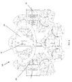
Each chamber is optically connected to an integrating light mixing capsule 16 (not visible in FIG. 1 ), which is optically connected to a plurality of primary light modules 18. Each primary light module 18 represents a unique color or a unique band of visible or invisible electromagnetic radiation, described below. Primary light modules 18 are connected to housing 20, which is connected to chamber 12, as shown in FIG. 1 . Housing 20 also encloses integrating light mixing capsule 16.
Referring to FIG. 2 , primary light modules 18 are shown emitting primary light beams 22 into integrating light mixing capsule 16. Each primary light module emits a unique primary light of known color. Primary light modules 18 can be arranged in any orientation, e.g., parallel to each other as shown in FIG. 1 or radially toward each other as shown in FIG. 2 , or at any angle(s) relative to each other so long as optical lenses or mirrors can direct emitting light beams 22 into integrating light mixing capsule 16. For example, as shown in FIG. 3 , an emitting light beam 22 is focused or collimated by focusing lens 24. The focused light can be further conditioned through one or more conditioning lens 24, 26 before being redirected at mirror or optical reflector 28 toward curved reflector 30 before being finally re-directed toward integrating light mixing capsule 16. Optical sensors, such as spectral and/or luminosity sensors, discussed below, for each light beam 22 can be deployed at 26. As shown in FIG. 3 , a plurality of emitting light beams 22 are directed by curved reflector 30 into integrating light mixing capsule 16, where the light beams are mixed before exiting as mixed, uniform light 34, which represents a device dependent color and illuminates chamber 12 to show the consumers a paint color, as discussed above. Mixed light 34 may pass through lens/filter 35 and/or other exit optical devices 35 to enlarge and/or condition the beam before reaching chamber 12. Curved reflector 30 can have any curvature, and preferably has a parabolic shape. Curved reflector 30 may optionally have aperture 32 to allow other lights to enter integrating light mixing capsule 16. In one example, controlled ambient light enters integrating light mixing capsule 16 through aperture 32.
While a single curved reflector 30 can direct multiple light beams 22 into integrating light mixing capsule 16, each light beam 22 can have its own dedicated curved reflector 30, as shown in FIG. 2 . In the arrangement shown in FIG. 2 , each light beam 22 is passed between two curved reflectors 30 to minimize cross-talk among the light beams, i.e., interferences caused by the proximity of multiple beams having different colors or frequencies.
Referring to FIGS. 4A and 4B , an embodiment of integrating light mixing capsule 16 is illustrated in detail. Integrating light mixing capsule 16 preferably has a hollow polyhedron shape and can have as many faces or facets as necessary. The faces of the polyhedron reflect light beams 22 that entered the mixing capsule to mix the beams. Mixing capsule 16, which can also be spherical or elliptical, has entrance port 36 adapted to receive light beams 22 and exit port 38 to emit mixed, uniform light 34. Integrating light mixing capsule 16 also has baffle 40, which is preferably positioned between entrance port 36 and exit port 38 to minimize the chance of a light beam 22 being able to exit mixing capsule 16 without being reflected therewithin and mixed. As shown, baffle 40 has three legs 42, which are connected to the sides of mixing capsule 16. Baffle 40 can have any number of legs 42, so long as it can be connected to mixing capsule 16 in a stable manner, and it allows lights to pass between the legs. The inside surfaces of mixing capsule 16 and baffle 40 can be coated by a reflective coating to increase reflectivity while minimizing the loss of light through light transmission through the walls of the mixing chamber and the baffle. Suitable coatings include, but are not limited to, barium sulfate or titanium dioxide. Furthermore, the inside surfaces of mixing capsule 16 should be matted, so that light would reflect from these matted surfaces hemispherically to increase the mixing effects. The center 44 of baffle 40 can have any shape including dome, as illustrated in FIG. 4A and pointed, as illustrated in FIG. 4B . Center 44 of baffle 40 should be larger than both entrance port 36 and exit port 38.
Exit optics located at 35 in another embodiment may comprise a projection lens with an internal beam restriction mask and adjustable aperture. These optical devices confine the projected mixed light to a fixed target, e.g., the bottom surface of chamber 12 or textured/curved surface 14, and to control the edge sharpness of the projected shape. Additionally, a filter mount can also be provided, which is sized and dimensioned to receive a number of filters, including but not limited to, neutral density filters to extend dynamic range and to balance luminance for comfortable viewing levels, center gradient filter to compensate for undesirable light edge fall-off that may occur at close projection distances (e.g., at large beam angle), spectral modification filters to remove undesirable wavelengths. Spectral modification filters can also be used to enhance primary light source, and would be mounted to intercept the primary light sources 22 before they enter the integrating light mixture capsule 16.
Another embodiment of integrating light mixing capsule 16 is shown in FIGS. 7A , 7B and 8. As shown in FIGS. 7A and 7B , a plurality of primary light modules 18 are positioned atop integrating mixing capsule 16, which comprises a plurality of first mixing chamber 50 and at least one central mixing chamber 52 and is positioned on top of viewing chamber 12 (omitted for clarity). Cooling fins 48 are provided to carry heat away from primary light modules 18. Each primary light module 18 emits light beams 22, as described above. As shown in FIG. 7A , aperture 32 discussed above is optionally provided. Light beams 22, as best shown in FIG. 8 , enter first mixing chamber 50 and are reflected off of first baffle wall 54. Light beams 22 are diffused after the first reflection throughout first chamber 50 and some are further reflected off of second baffle wall 56 or third baffle wall 58 (shown in FIGS. 7B and 8 ). Some reflected light may have multiple reflections among reflecting baffle walls 54, 56 and 58 and can be reflected back toward primary light modules 18. Eventually, reflected lights that originally emitted from primary light modules 18 enter central chamber 52. These lights are further reflected or mixed within central chamber 52 before exiting integrating light mixing capsule 16 at exit port 38 as mixed, uniform light 34. Optional exit optics 35, such as neutral density filters or lenses and other filters, can be placed within exit port 38 to further condition exiting light 34. Optical sensors, described below, can also be deployed within first mixing chambers 50 and/or central mixing chamber 52.
One advantage of the embodiment shown in FIGS. 7A , 7B and 8 is that light being mixed or reflected in central chamber 52 can re-enter first mixing chambers 50 for additional mixing before exiting integrating light mixing capsule 16. Another advantage of this embodiment is that a primary light module 18 can have multiple light sources 18(i), where each light source 18(i) can be different color stimuli of varying spectral power distribution (SPD) 22(i), that can be mixed in primary chambers 50. Any number of reflecting baffle walls can be employed. Preferably, the inner surfaces are also coated with reflective coating, as described above.
At least three primary light modules 18 should be used to represent colors in chamber 12. However, to have color gamut that is better than computer screens, which use either three primary colors (RGB), or printers, which use four primary colors (CMYK), at least five primary light modules should be used. As shown in FIGS. 1-2 , seven primary light modules 18 are used. Preferably, at least eleven primary light modules are used or more preferably at least 16 primary light modules are used.
The present invention is not limited to any number of LEDs or any particular color combination. Preferably at least five LEDs emitting different color light are used. More preferably, at least nine to eleven LEDs are used. Unique or different combinations of LEDs can be used to satisfy the particular application.
Color LEDs are widely available from many sources. Available LEDs can emit narrow bands of wavelengths or colors, as discussed in WO 2006/076211. LEDs are also available in broad bands, such as white LEDs. Broadband LEDs are generally produced by combining the entire available colored or narrow band LEDs to produce white or near white light. Broadband LEDs are commercially available through STMicroelectronics of Geneva, Switzerland, among other sources. When white LEDs and color LEDs are used, more colors can be displayed for the consumers and hence more paint colors can be displayed. Broad band LEDs that are less than white can be used in combination with other broad band LEDs that are also less than white, or with narrow band LEDs.
In an alternative embodiment, chamber 12 can be illuminated by LEDs, transistors or photocells constructed from organic polymers, available from Cambridge Display Technology or Plastic Logic Ltd. Polymer light emitting devices are disclosed in U.S. Pat. Nos. 5,807,627, 5,747,182, 5,653,914, 6,777,706, 6,723,811, 6,580,212, 6,559256, 6,498,049, and United States published patent applications 2004/0214039, 2004/0132226, 2004/0075381, 2004/0059077, 2003/0166810, 2003/0008991, and related patent references, including patent references sharing at least one inventor with the cited patent references. These references are incorporated by reference in their entireties.
In a preferred embodiment of the present invention, primary light modules 18 each has a bandwidth of about 25 nm, and the bandwidths of these light modules are spaced about 5 to about 10 nm apart. Fluorescent, incandescent, halogen, laser and other conventional light sources can also be used. Primary light modules can also be coated with fluorescent and phosphorous coatings. As discussed above, electromagnetic radiation in the invisible range can also be used as a primary light. In one example, ultraviolet radiation is emitted from a primary light module 18. The UV radiation can be converted by the coatings within mixing capsule 16, e.g., by altering its frequency, to change the UV radiation into blue light, to further increase the color gamut of the present invention. Other invisible electromagnetic radiations can also be changed to visible electromagnetic radiation by known methods.
In accordance with another aspect of the present invention, the color inconstancy effect can be minimized for the consumers. Color display device 10 can simulate the ambient light conditions that exist at the consumer's dwellings or offices. Simulated ambient light can be mixed with the primary lights, for example by introducing simulated ambient light through aperture 32 of curved reflector 30, discussed above. Also, one of the primary light modules 18 can be programmed or designed to emit simulated ambient light. As used herein simulated ambient light or simulated ambient condition includes simulated daylight, halogen, incandescent or fluorescent lights, other ambient lights, or combinations thereof. Furthermore, simulated ambient light can be diffused and introduced separately and directed to chamber 12.
An advantage of the present invention is that the consumers can be shown the same physical paint color under various simulated ambient conditions. For example, a paint color can be shown in daylight with color temperatures of 5000, 5500, 6500 or 7500 Kelvin, and simulated ambient light at sunrise or sunset can be displayed by adding a tungsten filament lamp (2856 Kelvin), these illumination sources can be mixed to arrive at a desirable ambient condition, so that the consumers can view the paint colors between cool (6500 Kelvin) and warm (2856 Kelvin). The consumers can view the same paint color at sunrise, mid-day, sunset or evening, to ascertain how a room would look throughout the day. Furthermore, the consumers can view how the paint may look in a sunny room versus a shady room, and may adjust the paint colors so that all the rooms in a dwelling may look substantially the same, if desired.
Primary light modules 18 and the other optical components are preferably controlled electronically by a computer or a central processing unit (collectively CPU). Among other things, the CPU controls the amount of luminance of each light module 18 by dimming the LEDs contained in the light modules 18. Dimming LEDs can be accomplished by pulse width modulation (PWM). PWM uses varying pulse widths to vary the percentage of “on” and “off” time of a LED to effect dimming. This typically occurs at high speeds to minimize flickering or strobing to the consumers. For example, dimming an LED at 25% can be achieved with PWM by pulsing the LED to the on position at 25 μs and to the off position for 75 μs, and so on.
In accordance with another aspect of the present invention, LED dimming can be accomplished by selectively adding a number of available waves of repeating pulses. As shown in FIG. 6 , four exemplary waves of pulses are shown. The first wave has repeating pulses with a width of one unit (e.g., each unit=10 μs). The second wave is offset from the first wave and its pulses start when the pulses from the first wave end, and the repeating pulses from the second wave have a width of two units. The third and fourth waves are similarly constructed with the pulses from the third wave having a four unit width and the pulses from the fourth wave having an eight unit width. It is to be noted that these widths can be any convenient size. According to this method, the time duration of all the available pulses in one cycle is 15 units (eight+four+two+one). To dim a LED at ⅓ its luminance, only the first and third waves are used. To dim a LED at about ½ its luminance, either only the fourth wave or a combination of the first, second and third waves is used. This method is an improvement over PWM, because a LED can be quickly dimmed to any fraction of its luminance without reprogramming the timing circuit. The higher number of waves can produce more gradation in the dimming effect. All the waves can be used to drive a single LED or each wave can be used to drive a single LED.
Through dimming, the amount or intensity of emitting light from each light module 18 can be controlled and mixed in light mixing capsule 16, so that mixed, uniform light 34 of different colors 34 can be displayed in chamber 12. Neutral density filters can also be used to evenly reduce the intensity of the displayed colors.
The CPU may also execute a procedure for selecting groups of colors in harmony or emotion or coordination in accordance to a tintometric system. A suitable procedure is described in PCT publication no. WO 03/027958, which is incorporated herein by reference in its entirety. The CPU may also include voice activation command, keyboard, computer mouse, touch screen and other input/output devices to communicate with the consumers.
The CPU can create lightings or desirable spectral power distribution continuously to generate special or desirable colors and appearance effects of a physical complex picture or other physical objects characterized by a given set of spectral reflectance data. The present invention can predict the effect of color shifts by comparing the spectral power distribution (SPD) to the spectral reflectance data of the object colors.
The Spectral Reflectance Factor (R %) is the ratio of quantity of the radiant energy reflected from the test surface to the quantity of radiant energy reflected by the perfect white diffuser for a given wavelength based on the same illuminating and viewing geometry. Thus, without changing the SPD of the incident light, one can alter the color appearance of a test surface by changing its spectral quantity R %, e.g., a warmer sensation may be accomplished by increasing its R % at the longer wavelength (620-700 nm) by changing the prescription of the coating surface with more red paint.
SPD is the radiant energy quantity distributed over the visible wavelength range (˜400-700 nm). This radiant energy may be originated from additive mixing of two or more light sources, e.g., the simulated ambient light or mixed light 34 that comes out of the mixing capsule 16, and its spectral content can be further modified via selective wavelength absorption or other techniques. After exiting mixing capsule 16, the modified mixed light 34 with a new SPD can create a new color sensation upon reaching viewing chamber 12. For example, without changing the R % of the test surface of an object, one can render the color appearance of the same test surface warmer by boosting the incident light's SPD with a higher radiant energy content at the red wavelength range (620-700 nm) e.g., adding a red LED light.
The SPD and the R % are two parameters that can be utilized to predict the effect of color shifts in the following manner. First, the test surface, e.g., surface 14 described above, has a constant R % but mixed light 34 has variable SPD. In other words, test surface 14 remains the same and mixed light 34 can be changed to produce various colors as described herein. Employing the inventive integrating light mixing capsule 16 and the various primary light sources 18 and other optical devices, the SPD of mixed light 34 incidents onto test surface 14 or a mock object, which in this example is white, to create a desired color appearance. This is possible because the R % of the test surface is known and the SPD of incident mixed light 34 is also known or can be controlled by the CPU. Alternatively, given a white (or colored) test surface, the CPU can compute the required SPD of the incident mixed light(s) 34 to render the test surface “warmer/cooler”, “exciting/calming”, “clean/dirty”, “light/dark”, etc. An important feature of this device is to allow customers to visualize the alternative color options for color decision.
Second, incident mixed light 34 has a constant SPD, but the test surface has a variable R %. The primary light sources 18 and the integrating light mixing capsule 16 are used to output a desired incident light SPD, which can simulate the customer's home lighting or can be simulated ambient light. The inventive system can help the customers to select the color chips, which serve as the test surfaces, with desired color appearance or with certain color emotions, e.g., “warmer/cooler”, “exciting/calming”, “clean/dirty”, “light/dark”, etc. A preferred feature of this device is to allow customers to visualize the alternative color options for color decision. Furthermore, paint manufacturers can customize the color prescription or formula to create the required R % property in order to create the desired color effect.
Both of these methods can be combined so that the incident mixed light 34 can be varied or controlled and the test surfaces 14 can also be varied, so that the test surface can have colors other than white.
The CPU can also control the cooling of the primary light sources 18. When LEDs are used, their SPD or color outputs are subject to aging and thermal drifts. Hence, it is desirable to control the temperature of the LEDs to control their color outputs. One way of controlling the temperature is by fins 48, shown in FIGS. 7-8 , which is a passive cooling system and is not controlled by the CPU. Optical sensors such as spectral, luminosity and/or temperature sensors can be deployed and electronically connected to the CPU to measure the color or SPD output, the luminosity or the temperature of the LEDs. Electrical or electronic sensors, such as thermocouples or thermistors can also be used and be controlled by the CPU. Cooling fans, liquid coolant or any other known cooling mechanisms can be provided and/or controlled by the CPU to maintain the output and temperature of the LEDs at desirable levels. The cooling system can be housed in housing 20, shown in FIG. 1 .
LED outputs are also susceptible to variation due to aging. The electronic control system described above can also employ the SPD and/or luminosity sensors to compensate for the aging effects. The electronic control can also compensate the balance and drive of the primary light sources based optical feedback and predictive data sets to maintain the desired mixed output. This compensates for non-linear chromatic to luminosity emitter relationships, aging and environmental effects, which include simulated ambient lighting conditions.
The integrating light mixing capsules 16, described above, have the ability to display accurately certain color, such as browns, by a wide dynamic brightness range of the primary light modules 18. This is achieved by a high turndown ratio in the electronic dimming circuits (e.g., 1:500) coupled with neutral density filters at the exit optics.
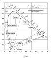
There are several CIE Chromaticity Diagrams: the CIE 1931 Chromaticity Diagram (based on two degree CIE Standard Observers) and the CIE 1964 Chromaticity Diagram (based on ten degree CIE Standard Observers). In 1976, CIE published two new uniform spaces: CIELAB and CIELUV. All these CIE recommendations can be used with the present invention. Other color order systems or color specifiers such as Pantone, Natural Color System, Munsell Color System, Hunter LAB system or the like, can also be used with the present invention. Some of these systems can be converted to the CIE diagram, e.g., the Munsell systems are convertible to CIE.
In accordance with one aspect of the present invention, each commercially available paint color from a palette, e.g., Benjamin Moore's color palette, is associated, calibrated or linked to a CIE colorimetric specification, and each device-dependent color is also associated or linked to a CIE colorimetric specification. Hence, each device-dependent color displayed in chamber 12 is associated with a paint color from the tens of thousands of commercially available paint colors.
As used herein, “true colors” or “device-independent colors” denote colors that are visible to the eyes, defined in CIE color space, without the need of a device, such as computer equipment, televisions, diodes, light emitting diodes (LEDs), projectors, computer displays, screens or the like. The “device-independent color space or profile connection color space” is based on the CIE 1931 standard colorimetric observer. This experimentally derived standard observer provides a very good representation of the human visual system with respect to color matching capabilities. Unlike device dependent color spaces (e.g., monitor RGB system), if two colors have the same CIE colorimetric specification, they will match if viewed under the same conditions as those defined for the CIE colorimetry. True colors of a surface include those that are visible when light reflects off that surface, or those that can be produced by pigmented compositions coated on the surface, such as paints and coatings. On the other hand, “device-dependent colors” are colors, defined in device color space, produced by the devices listed above. Typically, the device-dependent colors are produced within the devices by combinations of the spectral ranges within the visible radiation spectrum of electromagnetic radiation. The wavelengths of visible radiation spectrum range from below about 400 nm (violet) to above about 700 nm (red). In one example, the device-dependent colors can be created by combining different amount of the three primary colors: red (625-740 nm), green (520-565 nm) and blue (435-500 nm) or RGB, e.g., RGB computer monitors. The RGB convention represents approximate emission bands of wavelengths. Device-dependent colors can also be produced by mixtures of four process colors: cyan, magenta, yellow and black or CMYK, e.g., offset printing of color documents. The CMYK convention represents approximate absorption bands of wavelengths. Device-dependent colors based on RGB convention can be converted by known color management systems to CMYK convention and vice versa.
The light emitted from lamp 62 is broad band, e.g., incandescent, halogen, fluorescent, and can be divided into narrower bands to represent distinct colors. Optical filters 65 are narrow band filters capable of dividing the broad band light from lamp 62 into a plurality of primary lights. Mirror 64 directs light to the interior of chamber 60 for integrating light mixing prior to it being projected onto the textured surface 14 of viewing chamber 12.
In both FIGS. 11 and 12 , the intensity of the light from lamp 62, 66 is modulated by a light controller via digital modulation means including, but not limited to, current modulation, pulse modulation, liquid crystal phase modulation, digital micromirror orientation modulation, and combinations thereof.
Returning again to the discussion about the advantages of a full spectrum white LED, it is made up of a blue or UV LED with its envelope coated with a suitable mixture of phosphors. The LED light, in this case with blue or UV spectral quality, excites the phosphor coating that in turn creates light in the phosphor emission wavelength range. This results in a continuous full spectrum from about 400 nm to about 700 nm in the visible wavelength spectrum. By mixing the red, green and blue and other phosphors in various proportions, one can create light with a wide range of spectral characteristics from a very warm light to a very cool light with different color rendering power. FIG. 16 shows the relative spectral power distribution of a white LED, having a color temperature of about 4700 K, with its radiant power being modulated by a digital light controller at different levels from about 5% white to about 100% white. More particularly, the white LED is dimmable digitally with a wide dynamic range that can be achieved by modulating its pulse width and/or current. The radiant intensity at certain wavelengths, e.g., about 490 nm and beyond about 680 nm can be relatively weak. However, radiant intensity at these wavelengths can be supplemented with narrow LED sources having these wavelengths.
The full spectrum white LED is different from the tri-chromatic white LED whose spectral power distribution curve is given in FIG. 17 . The later mixes light from the red LED, green LED, and blue LED in different proportions to create white light with different color temperature. The radiant intensity of the tri-chromatic white LED is rich at/near to the wavelength(s) at the peak intensity of the RGB LEDs. The bandwidths at half power range from about 20 to about 35 nm depending on the individual LED. In other words, it is difficult to control the band width of the chromatic LED without further modulation by optical and/or digital means.
Because a full spectrum white LED emits radiant intensity in the entire visible wavelength range, it provides an opportunity to create highly desirable light primaries having peak wavelengths at a uniform interval (e.g., at most about 20 nm, preferably at most about 15 nm, and more preferably at most about 10 nm) from each other. This uniform “pitch” feature is an important factor in synthesizing color via additive mixing of the different light primaries. Advantageously, one can combine the full spectrum white LED with a chromatic LED having a peak intensity at one or more wavelengths where the white LED has weak intensity (e.g., about 490 nm and beyond about 680 nm), thereby boosting the relative spectral power at a broader range of wavelengths.
Optical modulation helps produce different light primaries confined to a narrow band of about 20 nm. More particularly, narrow band interference filters in lens mount 70, pass radiant energy with wavelengths within a certain range and reject wavelengths outside that range. Optical modulation is facilitated by the fact that LED illumination, unlike incandescent lamps, does not carry significant heat energy in its illuminating path. Rather, heat is generated at the LED junction in contact with the heat sink 67 where heat can be managed with an active cooling device 68. This is a preferred feature to help make optical modulation successful, as the presence of heat can be damaging to the optical narrow band interference filters.
Prior to optical modulation by means of narrow band interference filters, the dimmable white LED light can undergo digital modulation. As noted above, there are several means including, but not limited to, current modulation, pulse modulation, liquid crystal phase modulation, digital micromirror orientation modulation, and combinations thereof. More particularly, it has been discovered that a wide dynamic range can be achieved by modulating its pulse width and/or current. The pulse width can vary from 0.5 μs to 300 ms in steps of 0.1 μs. A more detailed explanation of pulse width modulation is provided above. The current can vary from 0.5 mA to 2 A in steps of 0.5 mA. This kind of dynamic range is difficult to achieve with conventional lamps such as incandescent and fluorescent lamps. An example of dimming LEDs is discussed above, and shown in FIG. 6 .
In a first stage, the plurality of primary light modules can each produce a light primary by a combination of optical and digital modulation of full spectrum white LED light. Subsequently, in a second stage, these modulated light primaries are additively mixed in integrating light chamber 16, 60. The intimately mixed light when projected onto a “mock” object can produce a color appearance matching a “target” color appearance in terms of spectral quality and gloss/sheen quality.
The concept of “appearance” matching is preferred to reflect the actual image observed by observers with normal color vision. For example, for a room painted with a single color using eggshell paint, an observer sees the entire room painted with a wide range of lighter and darker colors with more or less the same hue once the room light is switched on. This is because the observer sees the surface reflection (gloss/sheen with no color content), the body reflection (color content), as well as a wide range of mixed ratios of surface and body reflection. The surface reflection is the light specularly reflected from the paint surface (i.e., not modified by the paint colorant) whereas the body reflection is the light modified by the paint colorant and re-emerged from the paint that carries the color information. In addition, a “mock” object with a textured surface renders an additional dimension for appearance matching.
Innovatively, because one produces a broad range of light primaries (e.g., at least about 14, or at least about 16, or at least about 18, or at least about 24, or at least about 32), upon their mixing in the second stage, these light primaries can increase the available gamut of colors. As explained above, in connection with the discussion of FIG. 5 , additional LED primaries stretch outward the boundaries of the irregular polygon denoting the visible color gamut.
While it is apparent that the illustrative embodiments of the invention disclosed herein fulfill the objectives stated above, it is appreciated that numerous modifications and other embodiments may be devised by those skilled in the art. Additionally, feature(s) and/or element(s) from any embodiment may be used singly or in combination with other embodiment(s) and steps or elements from methods in accordance with the present invention can be executed or performed in any suitable order. One such modification is that the system of the present invention can be scaled down to a hand held device that can project with LED light the device-dependent colors onto a wall. Such a scaled down version can be used in the buyers' homes. Another possible modification is to incorporate the system of the present invention with image projection device so that images or text in addition to color simulation can be projected onto screen 52. Moreover, another possible modification allows one to use any of the primary light modules with any of the light mixing capsules or light mixing chambers. Therefore, it will be understood that the appended claims are intended to cover all such modifications and embodiments, which would come within the spirit and scope of the present invention.
Claims (37)
1. An optical system comprising at least one broad band primary light source and a plurality of primary light modules each comprising a narrow band filter, wherein the narrow band filter modulates the spectral quality of the broad band light source into a narrow band primary light, wherein the emitted narrow band primary lights from the primary light modules comprise unique narrow band lights, wherein the emitted narrow band primary lights are directed to an integrating light mixing chamber, wherein the emitted narrow band primary lights are mixed within the integrating light mixing chamber to form a mixed exit light, and wherein the mixed exit light is projected on to a display surface to display a color on said surface, wherein the integrating light mixing chamber comprises a plurality of first mixing chambers and at least one central mixing chamber and wherein at least one first mixing chamber is associated with only a single emitted narrow band primary light, and wherein each first mixing chamber comprises a plurality of reflecting baffle surfaces.
2. The optical system of claim 1 , wherein the emitted narrow band primary lights are reflected between the first mixing chambers and the central mixing chamber prior to exiting the integrating light mixing chamber.
3. The optical system of claim 1 , wherein the reflecting baffle surfaces inside the integrating light mixing chamber are treated to increase the mixing of the emitted primary light.
4. The optical system of claim 3 , wherein the surfaces are matted.
5. The optical system of claim 4 , wherein the surfaces are coated with barium sulfate or titanium dioxide.
6. The optical system of claim 1 , wherein the display surface forms a portion of a display chamber.
7. The optical system of claim 6 , wherein the optical system is positioned adjacent to the display chamber.
8. The optical system of claim 1 further comprising a cooling system to regulate the output of the emitted primary lights.
9. The optical system of claim 8 , wherein the cooling system comprises fins.
10. The optical system of claim 9 , wherein the cooling system comprises sensors connected to a controller.
11. The optical system of claim 1 further comprising simulated ambient light.
12. The optical system of claim 11 , wherein the simulated ambient light comprises simulated daylight, halogen, incandescent or fluorescent light or combinations thereof.
13. The optical system of claim 11 , wherein one of the primary light sources emits simulated ambient light.
14. The optical system of claim 11 , wherein the simulated ambient light is varied by a controller.
15. The optical system of claim 1 , wherein the display surface is curved.
16. The optical system of claim 1 further comprising a three-dimensional object with at least one curved surface to receive the mixed exit light.
17. The optical system of claim 1 further comprising at least one optical device to condition the mixed exit light.
18. The optical system of claim 17 , wherein the optical device comprises a neutral density filter, a center gradient filter, a spectral modification filter, a projection lens with an internal beam restriction mask or adjustable aperture.
19. The optical system of claim 1 , wherein the display surface is textured to simulate a paint finish.
20. The optical system of claim 1 , wherein the display surface is a diffusing surface.
21. The optical system of claim 1 , wherein the integrating light mixing chamber further comprises at least one baffle that locates therewithin and prevents the emitted primary lights from exiting the integrating light mixing chamber without reflecting from the baffle.
22. The optical system of claim 1 , wherein at least one of the reflecting baffle surfaces is formed by an internal member to the integrating light mixing chamber.
23. An optical system comprising at least one broad band primary light source and a plurality of primary light modules each comprising a narrow band filter, wherein the narrow band filter modulates the spectral quality of the broad band light source into a narrow band primary light, wherein the emitted narrow band primary lights from the primary light modules comprise unique narrow band lights, wherein the emitted narrow band primary lights are directed to an integrating light mixing chamber, wherein the emitted narrow band primary lights are mixed within the integrating light mixing chamber to form a mixed exit light, and wherein the mixed exit light is projected on to a display surface to display a color on said surface,
wherein integrating light mixing chamber comprises a plurality of reflecting baffle surfaces that form a plurality of first mixing chambers and at least one central mixing chamber.
24. The optical system of claim 23 , wherein the integrating light mixing chamber further comprises at least one baffle that locates therewithin and prevents the emitted primary lights from exiting the integrating light mixing chamber without reflecting from the baffle.
25. The optical system of claim 24 , wherein the integrating light mixing chamber has an entrance port and an exit port and the baffle is dimensionally larger than the entrance port and is located between the entrance port and the exit port.
26. The optical system of claim 25 , wherein the integrating light mixing chamber is a polyhedron.
27. The optical system of claim 25 , wherein the baffle comprises a dome portion.
28. The optical system of claim 25 , wherein the baffle comprises a pointed portion.
29. The optical system of claim 25 , wherein the baffle is connected to the integrating light mixing chamber by a plurality of legs.
30. The optical system of claim 23 , wherein the emitted narrow band primary lights have a peak wavelength at a uniform interval of at most about 20 nm.
31. The optical system of claim 23 , wherein the at least one broad band primary light source is selected from the group consisting of fluorescent, incandescent, halogen, laser, white LED, chromatic LED light, and combinations thereof.
32. The optical system of claim 31 , wherein the at least one broad band primary light source comprises different broad band light sources.
33. The optical system of claim 31 , wherein the at least one broad band primary light source comprises identical broad band light sources.
34. The optical system of claim 33 , wherein the at least one broad band primary light source comprises white LED light.
35. A method for appearance matching a color comprising the steps of:
(a) providing an optical system comprising a plurality of primary light modules and supplying at least one broad band light source to the plurality of light modules;
(b) modulating the at least one broad band light source supplied to the primary light sources into narrow band primary lights, wherein the narrow band primary lights comprise unique narrow band lights;
(c) dimming at least one narrow band primary light;
(d) mixing the unique narrow band primary lights in an integrating light mixing chamber to form a mixed exit light, wherein the integrating light mixing chamber comprises a plurality of reflecting baffle surfaces that form a plurality of first mixing chambers and at least one central mixing chamber; and
(e) projecting the mixed exit light on to a display surface to display a color on said surface.
36. The method of claim 35 , wherein the narrow band primary lights comprise a peak wavelength at a uniform interval of at most about 20 nm.
37. The method of claim 35 further comprising a step (f) of returning to step (b) if the display surface does not have an appearance matching a target appearance.
Priority Applications (1)
| Application Number | Priority Date | Filing Date | Title |
|---|---|---|---|
| US12/744,233 US8733949B2 (en) | 2007-12-24 | 2008-12-22 | System for representing colors including an integrating light capsule |
Applications Claiming Priority (3)
| Application Number | Priority Date | Filing Date | Title |
|---|---|---|---|
| US1653907P | 2007-12-24 | 2007-12-24 | |
| US12/744,233 US8733949B2 (en) | 2007-12-24 | 2008-12-22 | System for representing colors including an integrating light capsule |
| PCT/US2008/088011 WO2009082737A1 (en) | 2007-12-24 | 2008-12-22 | System for representing colors including an integrating light capsule |
Publications (2)
| Publication Number | Publication Date |
|---|---|
| US20100244700A1 US20100244700A1 (en) | 2010-09-30 |
| US8733949B2 true US8733949B2 (en) | 2014-05-27 |
Family
ID=40801579
Family Applications (1)
| Application Number | Title | Priority Date | Filing Date |
|---|---|---|---|
| US12/744,233 Active 2030-02-15 US8733949B2 (en) | 2007-12-24 | 2008-12-22 | System for representing colors including an integrating light capsule |
Country Status (5)
| Country | Link |
|---|---|
| US (1) | US8733949B2 (en) |
| EP (1) | EP2235434A4 (en) |
| CN (1) | CN102016401A (en) |
| CA (1) | CA2706498A1 (en) |
| WO (1) | WO2009082737A1 (en) |
Cited By (17)
| Publication number | Priority date | Publication date | Assignee | Title |
|---|---|---|---|---|
| US20120313980A1 (en) * | 2009-12-21 | 2012-12-13 | Martin Professional A/S | Cooling Module For Multiple Light Source Projecting Device |
| US8933638B2 (en) | 2011-05-15 | 2015-01-13 | Lighting Science Group Corporation | Programmable luminaire and programmable luminaire system |
| US9036244B2 (en) | 2011-03-28 | 2015-05-19 | Lighting Science Group Corporation | Wavelength converting lighting device and associated methods |
| US9036868B2 (en) | 2010-11-09 | 2015-05-19 | Biological Illumination, Llc | Sustainable outdoor lighting system for use in environmentally photo-sensitive area |
| US9125275B2 (en) | 2011-11-21 | 2015-09-01 | Environmental Light Technologies Corp | Wavelength sensing lighting system and associated methods |
| US9255670B2 (en) | 2013-03-15 | 2016-02-09 | Lighting Science Group Corporation | Street lighting device for communicating with observers and associated methods |
| US9265968B2 (en) | 2010-07-23 | 2016-02-23 | Biological Illumination, Llc | System for generating non-homogenous biologically-adjusted light and associated methods |
| US9274408B2 (en) * | 2010-05-28 | 2016-03-01 | Nec Display Solutions, Ltd. | Projection display device |
| US9353916B2 (en) | 2012-10-03 | 2016-05-31 | Lighting Science Group Corporation | Elongated LED luminaire and associated methods |
| US9581756B2 (en) | 2009-10-05 | 2017-02-28 | Lighting Science Group Corporation | Light guide for low profile luminaire |
| US9595118B2 (en) | 2011-05-15 | 2017-03-14 | Lighting Science Group Corporation | System for generating non-homogenous light and associated methods |
| US9693414B2 (en) | 2011-12-05 | 2017-06-27 | Biological Illumination, Llc | LED lamp for producing biologically-adjusted light |
| US9696005B2 (en) | 2012-05-06 | 2017-07-04 | Lighting Science Group Corporation | Tunable lighting apparatus |
| WO2017192384A1 (en) | 2016-05-06 | 2017-11-09 | Benjamin Moore & Co. | Aqueous paint compositions with soft feel and light diffusion effects |
| US10317020B1 (en) | 2015-11-03 | 2019-06-11 | Thomas McChesney | Paint color matching light |
| US20200103097A1 (en) | 2018-10-02 | 2020-04-02 | Electronic Theatre Controls, Inc. | Lighting fixture |
| US10845030B1 (en) | 2020-02-26 | 2020-11-24 | Electronic Theatre Controls, Inc. | Lighting fixture with internal shutter blade |
Families Citing this family (63)
| Publication number | Priority date | Publication date | Assignee | Title |
|---|---|---|---|---|
| EP2257131A1 (en) * | 2009-05-29 | 2010-12-01 | Koninklijke Philips Electronics N.V. | An auto-addressing method for a tiled lighting system |
| US9157581B2 (en) | 2009-10-05 | 2015-10-13 | Lighting Science Group Corporation | Low profile luminaire with light guide and associated systems and methods |
| US8465167B2 (en) | 2011-09-16 | 2013-06-18 | Lighting Science Group Corporation | Color conversion occlusion and associated methods |
| US9827439B2 (en) | 2010-07-23 | 2017-11-28 | Biological Illumination, Llc | System for dynamically adjusting circadian rhythm responsive to scheduled events and associated methods |
| US8841864B2 (en) | 2011-12-05 | 2014-09-23 | Biological Illumination, Llc | Tunable LED lamp for producing biologically-adjusted light |
| US8686641B2 (en) | 2011-12-05 | 2014-04-01 | Biological Illumination, Llc | Tunable LED lamp for producing biologically-adjusted light |
| US9681522B2 (en) | 2012-05-06 | 2017-06-13 | Lighting Science Group Corporation | Adaptive light system and associated methods |
| US9532423B2 (en) | 2010-07-23 | 2016-12-27 | Lighting Science Group Corporation | System and methods for operating a lighting device |
| US8547391B2 (en) | 2011-05-15 | 2013-10-01 | Lighting Science Group Corporation | High efficacy lighting signal converter and associated methods |
| US9024536B2 (en) | 2011-12-05 | 2015-05-05 | Biological Illumination, Llc | Tunable LED lamp for producing biologically-adjusted light and associated methods |
| RU2457393C1 (en) * | 2011-02-17 | 2012-07-27 | Закрытое Акционерное Общество "Научно-Производственная Коммерческая Фирма "Элтан Лтд" | Light-emitting diode source of white light with remote photoluminescent converter |
| US8608348B2 (en) | 2011-05-13 | 2013-12-17 | Lighting Science Group Corporation | Sealed electrical device with cooling system and associated methods |
| US8901850B2 (en) | 2012-05-06 | 2014-12-02 | Lighting Science Group Corporation | Adaptive anti-glare light system and associated methods |
| US9173269B2 (en) | 2011-05-15 | 2015-10-27 | Lighting Science Group Corporation | Lighting system for accentuating regions of a layer and associated methods |
| US9185783B2 (en) | 2011-05-15 | 2015-11-10 | Lighting Science Group Corporation | Wireless pairing system and associated methods |
| US8674608B2 (en) | 2011-05-15 | 2014-03-18 | Lighting Science Group Corporation | Configurable environmental condition sensing luminaire, system and associated methods |
| US8754832B2 (en) | 2011-05-15 | 2014-06-17 | Lighting Science Group Corporation | Lighting system for accenting regions of a layer and associated methods |
| US9648284B2 (en) | 2011-05-15 | 2017-05-09 | Lighting Science Group Corporation | Occupancy sensor and associated methods |
| US9681108B2 (en) | 2011-05-15 | 2017-06-13 | Lighting Science Group Corporation | Occupancy sensor and associated methods |
| WO2013031942A1 (en) | 2011-09-02 | 2013-03-07 | 三菱化学株式会社 | Lighting method and light-emitting device |
| CN105357796B (en) | 2011-09-02 | 2019-02-15 | 西铁城电子株式会社 | Means of illumination and light emitting device |
| US8847436B2 (en) | 2011-09-12 | 2014-09-30 | Lighting Science Group Corporation | System for inductively powering an electrical device and associated methods |
| US8408725B1 (en) | 2011-09-16 | 2013-04-02 | Lighting Science Group Corporation | Remote light wavelength conversion device and associated methods |
| US8492995B2 (en) | 2011-10-07 | 2013-07-23 | Environmental Light Technologies Corp. | Wavelength sensing lighting system and associated methods |
| US8439515B1 (en) | 2011-11-28 | 2013-05-14 | Lighting Science Group Corporation | Remote lighting device and associated methods |
| US8866414B2 (en) | 2011-12-05 | 2014-10-21 | Biological Illumination, Llc | Tunable LED lamp for producing biologically-adjusted light |
| US9289574B2 (en) | 2011-12-05 | 2016-03-22 | Biological Illumination, Llc | Three-channel tuned LED lamp for producing biologically-adjusted light |
| US8963450B2 (en) | 2011-12-05 | 2015-02-24 | Biological Illumination, Llc | Adaptable biologically-adjusted indirect lighting device and associated methods |
| US9220202B2 (en) | 2011-12-05 | 2015-12-29 | Biological Illumination, Llc | Lighting system to control the circadian rhythm of agricultural products and associated methods |
| US8976443B2 (en) | 2011-12-14 | 2015-03-10 | Columbia Insurance Company | System producing true colors using a digital micromirror device projector and method for controlling same |
| US8545034B2 (en) | 2012-01-24 | 2013-10-01 | Lighting Science Group Corporation | Dual characteristic color conversion enclosure and associated methods |
| US9402294B2 (en) | 2012-05-08 | 2016-07-26 | Lighting Science Group Corporation | Self-calibrating multi-directional security luminaire and associated methods |
| US8899776B2 (en) | 2012-05-07 | 2014-12-02 | Lighting Science Group Corporation | Low-angle thoroughfare surface lighting device |
| US8680457B2 (en) | 2012-05-07 | 2014-03-25 | Lighting Science Group Corporation | Motion detection system and associated methods having at least one LED of second set of LEDs to vary its voltage |
| US8899775B2 (en) | 2013-03-15 | 2014-12-02 | Lighting Science Group Corporation | Low-angle thoroughfare surface lighting device |
| US9006987B2 (en) | 2012-05-07 | 2015-04-14 | Lighting Science Group, Inc. | Wall-mountable luminaire and associated systems and methods |
| EP2664958B1 (en) * | 2012-05-18 | 2015-10-28 | Ricoh Company, Ltd. | Light source apparatus and image projection apparatus |
| JP6160274B2 (en) * | 2012-08-16 | 2017-07-12 | 株式会社リコー | Image projection device |
| CN102818158A (en) * | 2012-08-21 | 2012-12-12 | 福建百达光电有限公司 | Combined type LED (Light Emitting Diode) bulb lamp |
| US9174067B2 (en) | 2012-10-15 | 2015-11-03 | Biological Illumination, Llc | System for treating light treatable conditions and associated methods |
| US9322516B2 (en) | 2012-11-07 | 2016-04-26 | Lighting Science Group Corporation | Luminaire having vented optical chamber and associated methods |
| JP6179792B2 (en) * | 2013-02-26 | 2017-08-16 | 株式会社リコー | Light source device and image projection device provided with the same |
| JP6168387B2 (en) * | 2013-02-26 | 2017-07-26 | 株式会社リコー | Light source device and image projection device provided with the same |
| CN107018593B (en) * | 2013-03-04 | 2020-01-07 | 西铁城电子株式会社 | Light emitting device |
| US9303825B2 (en) | 2013-03-05 | 2016-04-05 | Lighting Science Group, Corporation | High bay luminaire |
| US9347655B2 (en) | 2013-03-11 | 2016-05-24 | Lighting Science Group Corporation | Rotatable lighting device |
| US9353935B2 (en) | 2013-03-11 | 2016-05-31 | Lighting Science Group, Corporation | Rotatable lighting device |
| US9459397B2 (en) | 2013-03-12 | 2016-10-04 | Lighting Science Group Corporation | Edge lit lighting device |
| US9018854B2 (en) | 2013-03-14 | 2015-04-28 | Biological Illumination, Llc | Lighting system with reduced physioneural compression and associate methods |
| US20140268731A1 (en) | 2013-03-15 | 2014-09-18 | Lighting Science Group Corpporation | Low bay lighting system and associated methods |
| US9151453B2 (en) | 2013-03-15 | 2015-10-06 | Lighting Science Group Corporation | Magnetically-mountable lighting device and associated systems and methods |
| US9157618B2 (en) | 2013-03-15 | 2015-10-13 | Lighting Science Group Corporation | Trough luminaire with magnetic lighting devices and associated systems and methods |
| US9222653B2 (en) | 2013-03-15 | 2015-12-29 | Lighting Science Group Corporation | Concave low profile luminaire with magnetic lighting devices and associated systems and methods |
| JP2014195184A (en) * | 2013-03-29 | 2014-10-09 | Funai Electric Co Ltd | Projector and head-up display device |
| JP6388637B2 (en) * | 2013-04-09 | 2018-09-12 | フィリップス ライティング ホールディング ビー ヴィ | Arrangement to change the visual appearance of the target object |
| US9429294B2 (en) | 2013-11-11 | 2016-08-30 | Lighting Science Group Corporation | System for directional control of light and associated methods |
| EP3091585A4 (en) | 2013-12-27 | 2017-07-26 | Citizen Electronics Co., Ltd | Light-emitting device and method for designing light emitting device |
| MX2016013002A (en) * | 2014-04-02 | 2017-07-19 | Airdye Intellectual Property Llc | Color management. |
| EP3289281A1 (en) | 2015-04-30 | 2018-03-07 | Cree, Inc. | Solid state lighting components |
| US10373112B2 (en) * | 2017-01-31 | 2019-08-06 | Behr Process Corporation | Color chip dispenser |
| US10991129B2 (en) * | 2017-06-12 | 2021-04-27 | Daniel Hickey | Paint color projector |
| EP3435742A1 (en) * | 2017-07-25 | 2019-01-30 | Koninklijke Philips N.V. | A light apparatus |
| CN109764268A (en) * | 2017-11-08 | 2019-05-17 | 长春工程学院 | A kind of hemisphere light source colour stereoscopic device |
Citations (22)
| Publication number | Priority date | Publication date | Assignee | Title |
|---|---|---|---|---|
| US5335158A (en) | 1992-05-21 | 1994-08-02 | Eastman Kodak Company | High efficiency linear light source |
| US5982957A (en) * | 1998-03-31 | 1999-11-09 | Eastman Kodak Company | Scanner illumination |
| US6191872B1 (en) | 1997-11-26 | 2001-02-20 | Eastman Kodak Company | Illuminator with light source arrays |
| US6259430B1 (en) | 1999-06-25 | 2001-07-10 | Sarnoff Corporation | Color display |
| US6513937B1 (en) * | 2000-09-19 | 2003-02-04 | Rockwell Collins, Inc. | Apparatus and method for integrating light from multiple light sources |
| US6733139B2 (en) * | 2000-06-05 | 2004-05-11 | Hewlett-Packard Development Company, L.P. | Projector with narrow-spectrum light source to complement broad-spectrum light source |
| US20040263791A1 (en) * | 2003-06-26 | 2004-12-30 | Chien-Hua Chen | Display system incorporating spectral separation and homogenization |
| US6888636B2 (en) | 2001-03-19 | 2005-05-03 | E. I. Du Pont De Nemours And Company | Method and apparatus for measuring the color properties of fluids |
| US20050162853A1 (en) | 2004-01-28 | 2005-07-28 | Kanti Jain | Compact, high-efficiency, energy-recycling illumination system |
| US20050232132A1 (en) | 2004-04-19 | 2005-10-20 | Tir Systems Ltd. | Parallel pulse code modulation system and method |
| US6985163B2 (en) | 2001-08-14 | 2006-01-10 | Sarnoff Corporation | Color display device |
| US20060007406A1 (en) * | 2002-10-21 | 2006-01-12 | Sean Adkins | Equipment, systems and methods for control of color in projection displays |
| US20060081773A1 (en) | 2003-06-23 | 2006-04-20 | Advanced Optical Technologies, Llc | Optical integrating chamber lighting using multiple color sources |
| US20060082732A1 (en) | 2004-10-15 | 2006-04-20 | Sanyo Electric Co., Ltd. | Projection type video display apparatus |
| US7038402B1 (en) | 2004-11-23 | 2006-05-02 | Dialog Semiconductor Gmbh | Combined exponential/linear RGB LED I-sink digital-to-analog converter |
| US7161313B2 (en) | 1997-08-26 | 2007-01-09 | Color Kinetics Incorporated | Light emitting diode based products |
| US7161311B2 (en) | 1997-08-26 | 2007-01-09 | Color Kinetics Incorporated | Multicolored LED lighting method and apparatus |
| US20070024824A1 (en) * | 2005-07-26 | 2007-02-01 | Niranjan Damera-Venkata | Projection of overlapping sub-frames onto a surface using light sources with different spectral distributions |
| US7186003B2 (en) | 1997-08-26 | 2007-03-06 | Color Kinetics Incorporated | Light-emitting diode based products |
| US7193632B2 (en) * | 2003-11-06 | 2007-03-20 | Behr Process Corporation | Distributed color coordination system |
| US20070153026A1 (en) | 2004-10-12 | 2007-07-05 | Ian Ashdown | Control apparatus and method for use with digitally controlled light sources |
| US20110306021A1 (en) * | 2008-12-12 | 2011-12-15 | Paul Mutimear | Display device |
-
2008
- 2008-12-22 EP EP08863960A patent/EP2235434A4/en not_active Withdrawn
- 2008-12-22 WO PCT/US2008/088011 patent/WO2009082737A1/en active Application Filing
- 2008-12-22 CA CA2706498A patent/CA2706498A1/en not_active Abandoned
- 2008-12-22 US US12/744,233 patent/US8733949B2/en active Active
- 2008-12-22 CN CN2008801226277A patent/CN102016401A/en active Pending
Patent Citations (22)
| Publication number | Priority date | Publication date | Assignee | Title |
|---|---|---|---|---|
| US5335158A (en) | 1992-05-21 | 1994-08-02 | Eastman Kodak Company | High efficiency linear light source |
| US7161313B2 (en) | 1997-08-26 | 2007-01-09 | Color Kinetics Incorporated | Light emitting diode based products |
| US7186003B2 (en) | 1997-08-26 | 2007-03-06 | Color Kinetics Incorporated | Light-emitting diode based products |
| US7161311B2 (en) | 1997-08-26 | 2007-01-09 | Color Kinetics Incorporated | Multicolored LED lighting method and apparatus |
| US6191872B1 (en) | 1997-11-26 | 2001-02-20 | Eastman Kodak Company | Illuminator with light source arrays |
| US5982957A (en) * | 1998-03-31 | 1999-11-09 | Eastman Kodak Company | Scanner illumination |
| US6259430B1 (en) | 1999-06-25 | 2001-07-10 | Sarnoff Corporation | Color display |
| US6733139B2 (en) * | 2000-06-05 | 2004-05-11 | Hewlett-Packard Development Company, L.P. | Projector with narrow-spectrum light source to complement broad-spectrum light source |
| US6513937B1 (en) * | 2000-09-19 | 2003-02-04 | Rockwell Collins, Inc. | Apparatus and method for integrating light from multiple light sources |
| US6888636B2 (en) | 2001-03-19 | 2005-05-03 | E. I. Du Pont De Nemours And Company | Method and apparatus for measuring the color properties of fluids |
| US6985163B2 (en) | 2001-08-14 | 2006-01-10 | Sarnoff Corporation | Color display device |
| US20060007406A1 (en) * | 2002-10-21 | 2006-01-12 | Sean Adkins | Equipment, systems and methods for control of color in projection displays |
| US20060081773A1 (en) | 2003-06-23 | 2006-04-20 | Advanced Optical Technologies, Llc | Optical integrating chamber lighting using multiple color sources |
| US20040263791A1 (en) * | 2003-06-26 | 2004-12-30 | Chien-Hua Chen | Display system incorporating spectral separation and homogenization |
| US7193632B2 (en) * | 2003-11-06 | 2007-03-20 | Behr Process Corporation | Distributed color coordination system |
| US20050162853A1 (en) | 2004-01-28 | 2005-07-28 | Kanti Jain | Compact, high-efficiency, energy-recycling illumination system |
| US20050232132A1 (en) | 2004-04-19 | 2005-10-20 | Tir Systems Ltd. | Parallel pulse code modulation system and method |
| US20070153026A1 (en) | 2004-10-12 | 2007-07-05 | Ian Ashdown | Control apparatus and method for use with digitally controlled light sources |
| US20060082732A1 (en) | 2004-10-15 | 2006-04-20 | Sanyo Electric Co., Ltd. | Projection type video display apparatus |
| US7038402B1 (en) | 2004-11-23 | 2006-05-02 | Dialog Semiconductor Gmbh | Combined exponential/linear RGB LED I-sink digital-to-analog converter |
| US20070024824A1 (en) * | 2005-07-26 | 2007-02-01 | Niranjan Damera-Venkata | Projection of overlapping sub-frames onto a surface using light sources with different spectral distributions |
| US20110306021A1 (en) * | 2008-12-12 | 2011-12-15 | Paul Mutimear | Display device |
Non-Patent Citations (7)
| Title |
|---|
| European Search Report issued in connection with the corresponding European Patent Application No. 08863960.4 on Mar. 22, 2011. |
| Fryc, Irene et al. "LED-Based Spectrally Tunable Source for Radiometric, Photometric, and Colorimetric Applications." Optical Engineering 44(11), Nov. 2005. pp. 1-8. |
| Howell, W.D. "An Overview of the Electronic Drive Techniques for Intensity Control and Colour Mixing of Low Voltage Light Sources such as LEDs and LEPS." Artistic License (UK) Ltd. London 2002. |
| International Search Report and Written Opinion issued in connection with corresponding International Application No. PCT/US2008/088011 on Feb. 19, 2009. |
| Paohuoa, Pedro et al. "Bright Approaches to Microcontroller-Based LED Drivers." Freescale Semiconductor, Inc. 2008. |
| Reichmann, Michael. "The Modulation Transfer Function Explained." Modulation Transfer Function. http://www.luminous-lanscape.com/tutorials/understanding-series/. 2007. |
| Torres, Daniel. "Low-End 8-Bit MCUs Enable High-Brightness Automotive LED Control." Mechatropolis. 2008. |
Cited By (23)
| Publication number | Priority date | Publication date | Assignee | Title |
|---|---|---|---|---|
| US9581756B2 (en) | 2009-10-05 | 2017-02-28 | Lighting Science Group Corporation | Light guide for low profile luminaire |
| US20120313980A1 (en) * | 2009-12-21 | 2012-12-13 | Martin Professional A/S | Cooling Module For Multiple Light Source Projecting Device |
| US8888294B2 (en) * | 2009-12-21 | 2014-11-18 | Martin Professional Aps | Cooling module for multiple light source projecting device |
| US9274408B2 (en) * | 2010-05-28 | 2016-03-01 | Nec Display Solutions, Ltd. | Projection display device |
| US9265968B2 (en) | 2010-07-23 | 2016-02-23 | Biological Illumination, Llc | System for generating non-homogenous biologically-adjusted light and associated methods |
| US9036868B2 (en) | 2010-11-09 | 2015-05-19 | Biological Illumination, Llc | Sustainable outdoor lighting system for use in environmentally photo-sensitive area |
| US9036244B2 (en) | 2011-03-28 | 2015-05-19 | Lighting Science Group Corporation | Wavelength converting lighting device and associated methods |
| US8933638B2 (en) | 2011-05-15 | 2015-01-13 | Lighting Science Group Corporation | Programmable luminaire and programmable luminaire system |
| US9595118B2 (en) | 2011-05-15 | 2017-03-14 | Lighting Science Group Corporation | System for generating non-homogenous light and associated methods |
| US9307608B2 (en) | 2011-11-21 | 2016-04-05 | Environmental Light Technologies Corporation | Wavelength sensing lighting system and associated methods |
| US9125275B2 (en) | 2011-11-21 | 2015-09-01 | Environmental Light Technologies Corp | Wavelength sensing lighting system and associated methods |
| US9693414B2 (en) | 2011-12-05 | 2017-06-27 | Biological Illumination, Llc | LED lamp for producing biologically-adjusted light |
| US9913341B2 (en) | 2011-12-05 | 2018-03-06 | Biological Illumination, Llc | LED lamp for producing biologically-adjusted light including a cyan LED |
| US9696005B2 (en) | 2012-05-06 | 2017-07-04 | Lighting Science Group Corporation | Tunable lighting apparatus |
| US9353916B2 (en) | 2012-10-03 | 2016-05-31 | Lighting Science Group Corporation | Elongated LED luminaire and associated methods |
| US9631780B2 (en) | 2013-03-15 | 2017-04-25 | Lighting Science Group Corporation | Street lighting device for communicating with observers and associated methods |
| US9255670B2 (en) | 2013-03-15 | 2016-02-09 | Lighting Science Group Corporation | Street lighting device for communicating with observers and associated methods |
| US10317020B1 (en) | 2015-11-03 | 2019-06-11 | Thomas McChesney | Paint color matching light |
| WO2017192384A1 (en) | 2016-05-06 | 2017-11-09 | Benjamin Moore & Co. | Aqueous paint compositions with soft feel and light diffusion effects |
| US20200103097A1 (en) | 2018-10-02 | 2020-04-02 | Electronic Theatre Controls, Inc. | Lighting fixture |
| US11149923B2 (en) | 2018-10-02 | 2021-10-19 | Electronic Theatre Controls, Inc. | Lighting fixture |
| US11162663B2 (en) | 2018-10-02 | 2021-11-02 | Electronic Theatre Controls, Inc. | Lighting fixture |
| US10845030B1 (en) | 2020-02-26 | 2020-11-24 | Electronic Theatre Controls, Inc. | Lighting fixture with internal shutter blade |
Also Published As
| Publication number | Publication date |
|---|---|
| EP2235434A1 (en) | 2010-10-06 |
| WO2009082737A1 (en) | 2009-07-02 |
| CA2706498A1 (en) | 2009-07-02 |
| US20100244700A1 (en) | 2010-09-30 |
| CN102016401A (en) | 2011-04-13 |
| WO2009082737A9 (en) | 2010-08-26 |
| EP2235434A4 (en) | 2011-04-20 |
Similar Documents
| Publication | Publication Date | Title |
|---|---|---|
| US8733949B2 (en) | System for representing colors including an integrating light capsule | |
| Berns | Designing white‐light LED lighting for the display of art: A feasibility study | |
| CA2558957C (en) | Precise repeatable setting of color characteristics for lighting applications | |
| US7572028B2 (en) | Methods and apparatus for generating and modulating white light illumination conditions | |
| US20070235639A1 (en) | Integrating chamber LED lighting with modulation to set color and/or intensity of output | |
| US7750917B2 (en) | Method for representing true colors with device-dependent colors on surfaces and for producing paints and coatings matching the true colors | |
| Druzik et al. | Guidelines for selecting solid-state lighting for museums | |
| US20080232101A1 (en) | System for Representing True Colors with Device-Dependent Colors on Surfaces and for Producing Paints and Coatings Matching the True Colors | |
| WO2003024269A1 (en) | Methods and apparatus for generating and modulating white light illumination conditions | |
| Thompson | Psychophysical evaluations of modulated color rendering for energy performance of LED-based architectural lighting | |
| Rosenfeld | Light, Colour and Vision (Part I) | |
| RavindraKumar et al. | A Tunable LED Daylight Luminaire for Textile and Printing Light Booth Application with Optimum LEDs | |
| Mangkuto et al. | The impact of correlated colour temperature variation from a tuneable LED lamp on colour sample appearance shift in CIELAB colour space | |
| Prechaveerakul et al. | Optical and electrical performance comparisons between high power LED and HMI studio lighting including the engineering economics analysis | |
| Yaoyuneyong | Effects of illuminants and retail environments on color of textiles fabric | |
| Manet’s | DISPLAYING ARTWORK 5 | |
| Petrulis | Colour rendition engineering and psychophysical assessment of the multicolour solid-state lighting | |
| Dikel | A new method in object lighting: Using surface chromaticity coordinates as a led-based lighting tool in museums | |
| Bullough | Measurement of light and color | |
| WO2006076211A2 (en) | System and method for representing true colors with device-dependent colors on surfaces and for producing paints and coatings matching the true colors | |
| Chakrabarti | Advanced optical design and control of multi-colored SSL system for stage lighting application. | |
| Vinh et al. | Optimization and Characterization of LED Luminaires for Indoor Lighting | |
| Fortner et al. | Hue, Saturation, Intensity | |
| Luo et al. | Lighting Quality Energy Efficiency | |
| Fairchild | THE VALUE PROPOSITION A Metric for the Aesthetic |
Legal Events
| Date | Code | Title | Description |
|---|---|---|---|
| AS | Assignment |
Owner name: COLUMBIA INSURANCE COMPANY, NEBRASKA Free format text: ASSIGNMENT OF ASSIGNORS INTEREST;ASSIGNORS:CHONG, PATRICK;GUTMAN, MICHAEL;MINCHEW, CARL;AND OTHERS;REEL/FRAME:022021/0318 Effective date: 20081215 |
|
| STCF | Information on status: patent grant |
Free format text: PATENTED CASE |
|
| FPAY | Fee payment |
Year of fee payment: 4 |
|
| MAFP | Maintenance fee payment |
Free format text: PAYMENT OF MAINTENANCE FEE, 8TH YEAR, LARGE ENTITY (ORIGINAL EVENT CODE: M1552); ENTITY STATUS OF PATENT OWNER: LARGE ENTITY Year of fee payment: 8 |