US8737005B1 - Adjusting heater current to reduce read transducer asymmetry - Google Patents
Adjusting heater current to reduce read transducer asymmetry Download PDFInfo
- Publication number
- US8737005B1 US8737005B1 US12/985,952 US98595211A US8737005B1 US 8737005 B1 US8737005 B1 US 8737005B1 US 98595211 A US98595211 A US 98595211A US 8737005 B1 US8737005 B1 US 8737005B1
- Authority
- US
- United States
- Prior art keywords
- heater
- asymmetry
- read transducer
- signal
- current
- Prior art date
- Legal status (The legal status is an assumption and is not a legal conclusion. Google has not performed a legal analysis and makes no representation as to the accuracy of the status listed.)
- Expired - Fee Related, expires
Links
Images


Classifications
-
- G—PHYSICS
- G11—INFORMATION STORAGE
- G11B—INFORMATION STORAGE BASED ON RELATIVE MOVEMENT BETWEEN RECORD CARRIER AND TRANSDUCER
- G11B5/00—Recording by magnetisation or demagnetisation of a record carrier; Reproducing by magnetic means; Record carriers therefor
- G11B5/48—Disposition or mounting of heads or head supports relative to record carriers ; arrangements of heads, e.g. for scanning the record carrier to increase the relative speed
- G11B5/58—Disposition or mounting of heads or head supports relative to record carriers ; arrangements of heads, e.g. for scanning the record carrier to increase the relative speed with provision for moving the head for the purpose of maintaining alignment of the head relative to the record carrier during transducing operation, e.g. to compensate for surface irregularities of the latter or for track following
- G11B5/60—Fluid-dynamic spacing of heads from record-carriers
- G11B5/6005—Specially adapted for spacing from a rotating disc using a fluid cushion
- G11B5/6011—Control of flying height
- G11B5/607—Control of flying height using thermal means
-
- G—PHYSICS
- G11—INFORMATION STORAGE
- G11B—INFORMATION STORAGE BASED ON RELATIVE MOVEMENT BETWEEN RECORD CARRIER AND TRANSDUCER
- G11B20/00—Signal processing not specific to the method of recording or reproducing; Circuits therefor
- G11B20/10—Digital recording or reproducing
- G11B20/10009—Improvement or modification of read or write signals
- G11B20/10018—Improvement or modification of read or write signals analog processing for digital recording or reproduction
- G11B20/10027—Improvement or modification of read or write signals analog processing for digital recording or reproduction adjusting the signal strength during recording or reproduction, e.g. variable gain amplifiers
-
- G—PHYSICS
- G11—INFORMATION STORAGE
- G11B—INFORMATION STORAGE BASED ON RELATIVE MOVEMENT BETWEEN RECORD CARRIER AND TRANSDUCER
- G11B5/00—Recording by magnetisation or demagnetisation of a record carrier; Reproducing by magnetic means; Record carriers therefor
- G11B2005/0002—Special dispositions or recording techniques
- G11B2005/0005—Arrangements, methods or circuits
- G11B2005/001—Controlling recording characteristics of record carriers or transducing characteristics of transducers by means not being part of their structure
- G11B2005/0013—Controlling recording characteristics of record carriers or transducing characteristics of transducers by means not being part of their structure of transducers, e.g. linearisation, equalisation
- G11B2005/0016—Controlling recording characteristics of record carriers or transducing characteristics of transducers by means not being part of their structure of transducers, e.g. linearisation, equalisation of magnetoresistive transducers
Definitions
- a method involves adjusting current flowing through a heater of a read transducer to produce a magnetic field that reduces an asymmetry of a signal generated by the read transducer. Adjusting the current flow may involve changing a direction of the current flow.
- the asymmetry may be determined via a transfer curve test, and in such a case the transfer curve test may involve placing the read transducer in a variable magnetic field during manufacture of a device that comprises the read transducer.
- variations may include determining the asymmetry of the signal based on an output of the read transducer during operation of a data storage apparatus that comprises the read transducer.
- the heater is used to adjust a distance between the read head and a magnetic media.
- the read transducer may produce the signal in response to being proximate to a changing magnetic field of a magnetic media and/or the heater may include a joule heater.
- an apparatus in another embodiment, includes a read transducer that generates a signal in response to reading a magnetic media.
- the apparatus further includes a heater that is coupled to a power source.
- the power source adjusts a current flowing through the heater to produce a magnetic field that reduces an asymmetry of the signal of the read transducer.
- the power source may adjust the current flow by changing a direction of the current flow.
- the asymmetry may be determined via a transfer curve test.
- the apparatus may include controller configured to determine the asymmetry of the signal based on an output of the read transducer during operation of the apparatus and adjust the current flowing through the heater via the power source in response thereto.
- the heater is used to adjust a distance between the head and a magnetic media, and the heater may include a joule heater.
- a system in another embodiment, includes a read transducer that generates a signal in response to being in proximity to a magnetic media.
- the system also includes a heater and a controller coupled to the heater.
- the controller includes circuitry that adjusts a current flowing through the heater to alter a magnetic field that encompasses at least the read transducer. The altered magnetic field reduces an asymmetry of the signal generated by the read transducer.
- the controller may adjust the current flow by changing a direction of the current flow.
- the heater may be a joule heater that is used to adjust a distance between the head and the magnetic media.
- the controller further includes circuitry configured to determine the asymmetry of the signal based on an output of the read transducer during operation of the system and to adjust the current flowing through the heater in response thereto.
- FIG. 1A is a graph illustrating signal asymmetries according to an example embodiment
- FIG. 1B is a side view of a disk drive slider according to an example embodiment
- FIG. 2 is a graph illustrating correction of asymmetry according to an example embodiment
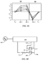
- FIG. 3A is a graph illustrating effects of heater current direction on read transducer resistance according to an example embodiment
- FIG. 3B is a circuit diagram illustrating selection of alternate current paths to affect read transducer asymmetry according to an example embodiment
- FIGS. 4A-4B are circuit diagrams illustrating selection from multiple heaters configurations to affect read transducer asymmetry according to an example embodiment
- FIGS. 5 and 6 are flowcharts illustrating procedures for adjusting heater current to reduce read transducer asymmetry according to example embodiments.
- signals generated by a read head in proximity to changing magnetic fields of a media may exhibit asymmetric output.
- a read head may exhibit different maximum amplitudes of signal output in response to being subjected to magnetic fields having the same strength but different directions. This asymmetry can make it more difficult to discern the underlying data that is encoded in the media.
- magnetic fields generated by a nearby heater e.g., a joule heater
- transducer heads of magnetic data storage devices such as hard drive apparatus. These concepts may be equally applicable to any other type of magnetic reading device that exhibits asymmetric output and that utilizes a heater or similar current consuming device. The concepts may be applicable to different types of transducer heads in such devices, such as separate read head transducers and/or combination read/write heads.
- a magnetic read head generally operates by detecting a changing magnetic field, e.g., changes in direction of magnetic flux caused by relative motion between an encoded magnetic media and the read head.
- the read head converts the flux reversals into an electrical analog signal that represents data stored on the media.
- An example of such an analog signal 112 is shown in FIG. 1A .
- This analog signal 112 is converted to a digital signal, e.g., via an analog-to-digital converter (ADC) in order to reconstruct the data originally recorded onto the media.
- ADC analog-to-digital converter
- the analog signal 112 generated by the read head would be substantially symmetric about a reference voltage (e.g., zero volts) as indicated by amplitude reference lines 114 , 116 that are symmetric about axis 118 .
- a reference voltage e.g., zero volts
- manufacturing inconsistencies and read head wear may cause the read head to generate an asymmetric analog signal from the magnetic media.
- FIG. 1A illustrates one example of asymmetry due to differing peak amplitudes, and other types of asymmetry may be observed.
- asymmetry may also include cases where the shape and/or area under the peaks of a signal above and below axis 118 are substantially different from each other.
- an asymmetric analog signal such as signal 112 is converted to a digital input signal
- the resulting digital conversion may exhibit an increased number of data read errors over what would be expected from a symmetric signal. These data errors may make the read head unsuitable for use in a newly manufactured magnetic media storage device, and/or cause problems in such device while in use. If the analog signals become more asymmetric through time (e.g., due to wear or aging of the read head), the useful life of the data storage device may be shortened. In other cases, this asymmetry may impact performance, e.g., increase the use of error correction algorithms to correct errors, increase the probability of an uncorrectable read error, etc.
- Asymmetry of the analog signal 112 may be detected in a number of ways. For example, during development and manufacturing, it is possible to test the response of the head to an applied magnetic field.
- One series of tests known as “Transfer Curve Testing,” involves placing a head in a magnetic field (steady state or time varying) and measuring the output signal from the read transducer.
- the transfer curve is a plot of the output signal versus the applied magnetic field, where the field is varied from a negative value to a positive value, the positive value having the same magnitude as the negative value.
- the output signal may include a steady state voltage which is a function of the bias current applied to the head, the bulk resistance of the head and/or the applied magnetic field.
- a number of characteristics can be measured from the transfer curve data, including symmetry. Determination of symmetry may involve performing a comparison of the read signal amplitude with a maximum positive field and the read signal amplitude with a maximum negative field.
- a circuit may accumulate a sum of positive and negative peak values of the analog read head signal. These accumulated valued can be averaged, and a level of asymmetry can be defined based on these average values.
- a storage device described herein may include features to reduce this symmetry at the read head before the asymmetric signal reaches an ADC and/or related circuits.
- a block diagram shows a side view of a slider 106 that include features designed to reduce magnetic transducer asymmetries as discussed above.
- the slider 106 is coupled to arm 104 by way of a suspension 202 that allows some relative motion between the slider 106 and arm 104 .
- the slider 106 includes a read transducer 204 at a trailing edge.
- a flying height 208 is maintained between the slider 106 and surface 206 by a downward force of arm 104 . This downward force is counterbalanced by an air cushion that exists between the surface 206 and an air bearing surface 210 of the slider 106 when the disk 102 is rotating.
- slider flying heights to be 4 millionths of an inch or less. Even so, variables such factors as data surface roughness, manufacturing tolerances, and unpredictable air bearing disturbances, all make it difficult to maintain a constant slider flying height. Also, the expansion and contraction of components due to changes in temperature have a more pronounced impact at lower slider flying heights.
- the slider 106 may be configured such that a transducing region 211 of the slider 106 changes geometry in response to changes in temperature. This is shown in FIG. 1B by dotted line that represents a change in geometry of the transducing region 211 that may be induced in response to an increase or decrease in temperature.
- the shape and magnitudes of this changing geometry can be built into the slider, e.g., by forming the transducing region 211 from a different material than other parts of the slider 106 . In such a case, changes in temperature causes a deformation in this area 211 due to different thermal expansion properties of the different materials.
- selective application of heat to the slider 106 can be used to finely adjust the effective fly height 208 of the read transducer 204 , e.g., as measured between the read transducer 204 and media surface 206 .
- the slider 106 may include (or otherwise be thermally coupled to) a heating element 212 .
- This heating element 212 e.g., a resistance heater
- the heating element 212 can be mounted at a variety of locations (e.g., near transducing region 211 ) and in a manner that minimizes its influence on the aerodynamic properties of the slider.
- the heat generated by heating element 212 is generally proportional to an amount of current flowing through heating element 212 .
- the amount of current flowing through the heating element 212 may be dictated by feedback signals, such as temperature measurements of the slider 106 and/or characteristics of signals being read by the transducer 204 .
- the read transducer 204 generates electrical signals in response to moving through lines of magnetic flux.
- Modern hard drive read transducers commonly use materials with magnetoresistance (MR), giant magnetoresistance (GMR), tunneling magnetor resistance (TMR) properties to generate these signals.
- MR magnetoresistance
- GMR giant magnetoresistance
- TMR tunneling magnetor resistance
- the resistance of an MR/GMR/TMR read head changes in accordance to characteristics of magnetic fields of the disk 104 while moving proximate to the read transducer 204 .
- the slider 106 may also include a separate or merged but physically proximate write transducer (not shown).
- the write transducer utilizes properties of electromagnetism to magnetically encode data on the disk 104 in response to an electrical signal.
- electromagnetism used by write transducers is the generation of magnetic fields by an electrical current flowing through a conductor. These magnetic fields (sometimes referred to as “Ampere magnetic fields”) are often visualized as a pattern of circular field lines surrounding the conductor through which current is flowing.
- the write transducer typically takes advantage of this property by sending current through a conductor surrounding a write pole, thereby generating a magnetic field at a tip of the write pole.
- any current carrying conductor may produce a magnetic field.
- the heating element 212 utilizes current to produce heat, and so it follows that the heating element 212 and/or associated conductors that supply current to the heating element 212 will also generate magnetic fields. These fields are generally indicated in FIG. 2A by reference numeral 214 .
- the magnetic fields 214 produced via the heating element may be considered a form of interference that needs to be dealt with by the system designer, e.g., through the addition of shielding, routing of conductors, etc.
- the magnetic fields produced by the heater may be put to good use in improving performance of the device. For example, if an external magnetic field can effectively shift the asymmetric signal 112 in FIG. 1A downward, the resulting signal may be significantly more symmetric, and therefore less like to produce errors and/or require other (possibly resource intensive) corrective measures.
- an apparatus may include features that utilize magnetic fields generated by a read heater 212 and similar current-consuming devices in order to provide asymmetry correction for read heads. Such asymmetry correction may occur by specific placement of conductors, selection of heater current direction, etc., during a design phase of the device. Methods, systems, and apparatuses described herein may also take active measures to correct for asymmetry. One of these active measures is shown in FIG. 2 , which illustrates correction of asymmetry by way of reversing direction of current flow in a heater or similar slider-mounted electrical component.
- the graph of FIG. 2 may represent distributions of any signal characteristics (e.g., amplitudes) that characterize symmetry of the signal about a reference point (e.g., zero volts).
- the y-axis of FIG. 2 represents a population of measurements, and the x-axis represents asymmetry of the measurements.
- x ⁇ 0 and x>0 the measurements are negatively and positively asymmetric, respectively.
- Signals obtained from read transducers that read an encoded pattern of continuously alternating positive and negative flux directions may exhibit a distribution of signal outputs such as 220 if the transducer outputs are significantly symmetrical.
- Distribution 222 may represent analogous signal outputs that exhibit significant positive and/or negative asymmetry.
- a direction of the current flow may be selected that decreases the asymmetry. This selection of a current direction is indicated by arrows 226 and 228 , which result in respective positive and negative corrective magnetic fields.
- Transducers that exhibit positive asymmetry may have a negative field 228 applied, and transducers with negative asymmetry may have a positive field 226 applied.
- a graph illustrates the effect of changing heater current flow direction on resistance of a reader head due to magnetic fields created by the heater.
- Each of the data sets (those data points in FIG. 3A that are represented by a common symbol) represents an influence on reader resistance at different head temperatures for a different heater designs.
- the data points in a first portion 302 of the graph represent changes to reader head resistance in a first direction of current flow, and the data points in a second portion 304 of the graph represent resistance change for an opposite direction of current flow.
- a direction reversal of current being supplied to a slider-integrated heater can be chosen so as reduce asymmetry exhibited by a read transducer.
- the direction of heater current flow may be adapted/modified to reduce head asymmetry during design, manufacture, and/or operation.
- the design of circuitry for selecting current flow direction in this way is known in the art (e.g., by selecting/reversing polarity of voltage applied to the heater), and therefore is not discussed in greater detail.
- the direction of current flow may be selected statically (e.g., set once) or dynamically (e.g., via a control circuit) at any time, including design phase, manufacturing, and/or while in use.
- the amount of asymmetry correction may be dependent on the amount of current flowing through the heater, which may be dependent on a desired temperature of the slider.
- slider temperature may be set based on a desired distance between the read transducer and the media, and without regards to asymmetry of the read signal.
- the amount of current flowing at a particular time may not be enough to fully correct read transducer asymmetry.
- a small amount of asymmetry correction is better than none, and therefore selection of current direction through the heater may be a straightforward way to provide such correction.
- the read signal may currently sufficiently symmetric, in which case there may be no need for asymmetry correction via heater-induced magnetic fields.
- systems and apparatuses may also include features to statically and/or dynamically change the magnitudes of the magnetic fields induced by these currents, as well as the direction.
- a circuit diagram illustrates an example of how current flowing through a heating element 312 may be adapted to positively affect read transducer output signal symmetry.
- Current may flow through a slider heating element 312 in either a reverse or forward direction, e.g., in response to a voltage applied from a controller 314 as described above.
- a number of conductive paths 316 - 318 may be available to supply the current to the heater element 312 , wherein any combination of the paths 316 - 318 may be active/available at a give time.
- the choice of paths 316 - 318 may have a measureable difference in the magnetic fields generated by the current flowing through the paths 316 - 318 , in particular the magnetic fields that influence symmetry of the signal output from a read transducer.
- the paths 316 - 318 may have a number of different characteristics. For example, some of the paths 316 - 318 may be routed closer to a read transducer than others of the paths 316 - 318 . In such a case, sending current through different combinations of the paths can change an amount of magnetic flux created by activation of the heater 312 . Other differences between the paths 316 - 318 may include differences in path length, convolution, magnetic shielding, cross sectional area, or any other characteristic that may influence an amount of magnetic flux caused by activation of the heater 312 .
- the paths 316 - 318 may be dynamically selected by the controller 314 , e.g., in response to an amount of current presently being sent to the heater and/or amount of asymmetry of a read transducer output signal 322 .
- the paths may be selected during manufacture.
- the circuit may include features such as fuses 320 - 321 , which may cause an open circuit along any of respective paths 316 , 317 in response to, e.g., application of energy such as an over-current or radio frequency radiation.
- Certain paths may not include any such fuse, e.g., to ensure at least one current path remains in place in case of accidental application of energy (e.g., static electricity) or other event that might open the fuses 320 , 321 .
- energy e.g., static electricity
- FIGS. 4A-4B Other variations on heater design may enable changing an amount of magnetic flux induced from a heater current. Examples of these designs are shown in FIGS. 4A-4B .
- parallel heaters 402 , 404 may be selectably activated, either dynamically by way of controller 406 , or statically by way of fuse elements 408 , 409 . This may affect current flowing through parallel heater branches and/or common conductor paths, and side effects may have to be considered in heater control design (e.g., affects on response times).
- FIG. 4B multiple heaters 412 and 414 are also used. In this case, a switch element 410 selects whether multiple heaters 412 , 414 are activated in parallel or in series.
- the switch 410 may be a one-time activated component similar to fuse, or may be implemented in controller 416 , which may dynamically change wiring of the heater 412 , 414 based on current conditions.
- FIGS. 3B , 4 A and 4 B are provided for purposes of illustration and not of limitation. These examples can be readily adapted to change the number of heating elements and paths from those illustrated, and to combine features therebetween. For example, any of these circuits can be enabled to reverse a direction of heater current in order to positively influence asymmetries of a read transducer signal. These concepts may also be applied to other current carrying components located proximate to a read head, e.g., lasers, write heads, heat-assisted magnetic recording (HAMR) components, etc.
- HAMR heat-assisted magnetic recording
- a flowchart illustrates a procedure 502 for adjusting heater current to reduce read head transducer asymmetry according to an example embodiment.
- a voltage +V is applied 504 to induce a first direction of current flow through a heater of a read transducer.
- An asymmetry A1 of an output signal of the read transducer is determined 506 in response to the current flowing in the first direction.
- a reverse voltage ⁇ V is applied 508 to the heater, and a second asymmetry A2 is determined 510 based on the reverse current flow. If it is determined 512 that A1>A2 (e.g., more asymmetry due to +V) then ⁇ V is used 516 to drive the heater, otherwise +V is used 514 .
- FIG. 6 a flowchart illustrates another procedure 602 according to an example embodiment.
- An asymmetry is determined 604 of a signal generated by a read head in proximity to a changing magnetic field of a magnetic media.
- a current flowing through a joule heater of the read head is adjusted 606 to cause a change to a magnetic field generated by the current.
- the change to the magnetic field generated by the current is intended to reduce the asymmetry of the signal, and this effect may optionally be determined 608 as part of the procedure.
Abstract
Description
Claims (19)
Priority Applications (1)
| Application Number | Priority Date | Filing Date | Title |
|---|---|---|---|
| US12/985,952 US8737005B1 (en) | 2011-01-06 | 2011-01-06 | Adjusting heater current to reduce read transducer asymmetry |
Applications Claiming Priority (1)
| Application Number | Priority Date | Filing Date | Title |
|---|---|---|---|
| US12/985,952 US8737005B1 (en) | 2011-01-06 | 2011-01-06 | Adjusting heater current to reduce read transducer asymmetry |
Publications (1)
| Publication Number | Publication Date |
|---|---|
| US8737005B1 true US8737005B1 (en) | 2014-05-27 |
Family
ID=50736505
Family Applications (1)
| Application Number | Title | Priority Date | Filing Date |
|---|---|---|---|
| US12/985,952 Expired - Fee Related US8737005B1 (en) | 2011-01-06 | 2011-01-06 | Adjusting heater current to reduce read transducer asymmetry |
Country Status (1)
| Country | Link |
|---|---|
| US (1) | US8737005B1 (en) |
Cited By (1)
| Publication number | Priority date | Publication date | Assignee | Title |
|---|---|---|---|---|
| US10008229B2 (en) | 2016-01-05 | 2018-06-26 | Western Digital Technologies, Inc | Implementing enhanced track following during read back using head asymmetry metrics in hard disk drives |
Citations (10)
| Publication number | Priority date | Publication date | Assignee | Title |
|---|---|---|---|---|
| US5991113A (en) | 1997-04-07 | 1999-11-23 | Seagate Technology, Inc. | Slider with temperature responsive transducer positioning |
| US6483297B2 (en) | 2000-12-29 | 2002-11-19 | Texas Instruments Incorporated | Method and apparatus for characterizing asymmetries of an MR head |
| US20040240096A1 (en) * | 2002-05-06 | 2004-12-02 | Lydia Baril | System and method for pre-stressing a read head for improving performance thereof |
| US20050162785A1 (en) | 2004-01-22 | 2005-07-28 | Seagate Technology Llc | ESD shunt for transducing head |
| US20050207053A1 (en) * | 2004-03-22 | 2005-09-22 | Barnett Raymond E | Write current waveform asymmetry compensation |
| US20060052905A1 (en) * | 2004-09-03 | 2006-03-09 | Watlow Electric Manufacturing Company | Power Control system |
| US7102839B2 (en) * | 2003-10-31 | 2006-09-05 | International Business Machines Corporation | Magnetic recording channel utilizing control fields for timing recovery, equalization, amplitude and amplitude asymmetry |
| US7573682B2 (en) | 2005-06-16 | 2009-08-11 | Seagate Technology Llc | Writer heater for thermal protrusion shape control in a magnetic writer |
| US20100002327A1 (en) | 2008-07-01 | 2010-01-07 | David Ernest Call | Method for improving magnetic read sensor manufacturing using external and/or embedded heating element |
| US7656619B1 (en) * | 2003-06-05 | 2010-02-02 | Seagate Technology Llc | Magnetic head sliders for disk drives having a heating element and pedestal in thick undercoat layer |
-
2011
- 2011-01-06 US US12/985,952 patent/US8737005B1/en not_active Expired - Fee Related
Patent Citations (10)
| Publication number | Priority date | Publication date | Assignee | Title |
|---|---|---|---|---|
| US5991113A (en) | 1997-04-07 | 1999-11-23 | Seagate Technology, Inc. | Slider with temperature responsive transducer positioning |
| US6483297B2 (en) | 2000-12-29 | 2002-11-19 | Texas Instruments Incorporated | Method and apparatus for characterizing asymmetries of an MR head |
| US20040240096A1 (en) * | 2002-05-06 | 2004-12-02 | Lydia Baril | System and method for pre-stressing a read head for improving performance thereof |
| US7656619B1 (en) * | 2003-06-05 | 2010-02-02 | Seagate Technology Llc | Magnetic head sliders for disk drives having a heating element and pedestal in thick undercoat layer |
| US7102839B2 (en) * | 2003-10-31 | 2006-09-05 | International Business Machines Corporation | Magnetic recording channel utilizing control fields for timing recovery, equalization, amplitude and amplitude asymmetry |
| US20050162785A1 (en) | 2004-01-22 | 2005-07-28 | Seagate Technology Llc | ESD shunt for transducing head |
| US20050207053A1 (en) * | 2004-03-22 | 2005-09-22 | Barnett Raymond E | Write current waveform asymmetry compensation |
| US20060052905A1 (en) * | 2004-09-03 | 2006-03-09 | Watlow Electric Manufacturing Company | Power Control system |
| US7573682B2 (en) | 2005-06-16 | 2009-08-11 | Seagate Technology Llc | Writer heater for thermal protrusion shape control in a magnetic writer |
| US20100002327A1 (en) | 2008-07-01 | 2010-01-07 | David Ernest Call | Method for improving magnetic read sensor manufacturing using external and/or embedded heating element |
Non-Patent Citations (1)
| Title |
|---|
| Jang, "Magnetic and Thermal Effects of Flying Height Control Heater Voltage on Tunneling Magnetoresistive Heads", American Institute of Physics, Mar. 11, 2008, 3 pages. |
Cited By (1)
| Publication number | Priority date | Publication date | Assignee | Title |
|---|---|---|---|---|
| US10008229B2 (en) | 2016-01-05 | 2018-06-26 | Western Digital Technologies, Inc | Implementing enhanced track following during read back using head asymmetry metrics in hard disk drives |
Similar Documents
| Publication | Publication Date | Title |
|---|---|---|
| US7872824B1 (en) | Setting an operating bias current for a magnetoresistive head by computing a target operating voltage | |
| US7804657B1 (en) | Setting an operating bias current for a magnetoresistive head using ratio of target voltage and measured voltage | |
| US9390741B2 (en) | Head transducer with multiple resistance temperature sensors for head-medium spacing and contact detection | |
| US8854929B1 (en) | Disk drive calibrating laser power and write current for heat assisted magnetic recording | |
| JP5813057B2 (en) | Method, apparatus and magnetic head for determining head-disk contact and / or spacing | |
| KR0167809B1 (en) | Individual mr transducer head/disk/channel adaptive bias current system | |
| US9679598B2 (en) | Writer core incorporating thermal sensor having a temperature coefficient of resistance | |
| JP2006202391A (en) | Magnetic disk drive and method for measuring flying height | |
| US10580444B1 (en) | Bolometer and contact sensor arrangement for a heat-assisted magnetic recording device | |
| JP2004241105A (en) | Head used in drive, method for manufacturing and using the head, system for wrapping the head, storage device, and method for operating the storage device | |
| JP2014017045A5 (en) | ||
| US9093084B2 (en) | Flexible biasing strategy for ground-split TCR sensors | |
| CN113168846B (en) | Data storage device for detecting write assist element abnormality based on protrusion slope | |
| US9437234B1 (en) | Head-medium contact detection using high frequency heater oscillation | |
| US6123781A (en) | Method of controlling magnetic characteristics of spin-valve magnetoresistive element and of magnetic head with the element | |
| US9074941B1 (en) | Systems and methods for measuring ambient and laser temperature in heat assisted magnetic recording | |
| US8737005B1 (en) | Adjusting heater current to reduce read transducer asymmetry | |
| WO2000048173A1 (en) | Method for controlling bias current for magnetoresistive head, fixed magnetic recording device, and magnetic disc therefor | |
| EP0720285B1 (en) | Differential amplifier with proxy load for control of output common mode range | |
| US6255814B1 (en) | Method and apparatus for measuring bias magnetic field for controlling magnetic domain of magnetoresistive effect element | |
| CN109841233A (en) | The data storage device of multiple head sensor elements is used for using multi-mode sensing circuit | |
| US20070188166A1 (en) | Magnetic head testing apparatus and method of testing a magnetic head | |
| US9349415B1 (en) | Qualifying a recording head based on symmetry of a cross-track profile | |
| US10395690B2 (en) | Magnetic disk device and write capable of detecting data errors and performing read-write verification thereof | |
| US8976480B1 (en) | Method to convert and calibrate the embedded contact sensor signal to clearance and spacing information using interface voltage control |
Legal Events
| Date | Code | Title | Description |
|---|---|---|---|
| AS | Assignment |
Owner name: SEAGATE TECHNOLOGY LLC, CALIFORNIA Free format text: ASSIGNMENT OF ASSIGNORS INTEREST;ASSIGNORS:MACKEN, DECLAN;STOKES, SCOTT W.;WANG, JENNY J.;REEL/FRAME:025597/0930 Effective date: 20101223 |
|
| AS | Assignment |
Owner name: THE BANK OF NOVA SCOTIA, AS ADMINISTRATIVE AGENT, Free format text: SECURITY AGREEMENT;ASSIGNOR:SEAGATE TECHNOLOGY LLC;REEL/FRAME:026010/0350 Effective date: 20110118 |
|
| STCF | Information on status: patent grant |
Free format text: PATENTED CASE |
|
| FPAY | Fee payment |
Year of fee payment: 4 |
|
| FEPP | Fee payment procedure |
Free format text: MAINTENANCE FEE REMINDER MAILED (ORIGINAL EVENT CODE: REM.); ENTITY STATUS OF PATENT OWNER: LARGE ENTITY |
|
| LAPS | Lapse for failure to pay maintenance fees |
Free format text: PATENT EXPIRED FOR FAILURE TO PAY MAINTENANCE FEES (ORIGINAL EVENT CODE: EXP.); ENTITY STATUS OF PATENT OWNER: LARGE ENTITY |
|
| STCH | Information on status: patent discontinuation |
Free format text: PATENT EXPIRED DUE TO NONPAYMENT OF MAINTENANCE FEES UNDER 37 CFR 1.362 |
|
| FP | Lapsed due to failure to pay maintenance fee |
Effective date: 20220527 |