US8740646B2 - Connector having a shield mounted on a circuit board and extending through an aperture in a bracket - Google Patents
Connector having a shield mounted on a circuit board and extending through an aperture in a bracket Download PDFInfo
- Publication number
- US8740646B2 US8740646B2 US13/705,751 US201213705751A US8740646B2 US 8740646 B2 US8740646 B2 US 8740646B2 US 201213705751 A US201213705751 A US 201213705751A US 8740646 B2 US8740646 B2 US 8740646B2
- Authority
- US
- United States
- Prior art keywords
- connector
- shield
- terminals
- baseplate
- housing
- Prior art date
- Legal status (The legal status is an assumption and is not a legal conclusion. Google has not performed a legal analysis and makes no representation as to the accuracy of the status listed.)
- Active
Links
Images


Classifications
-
- H—ELECTRICITY
- H01—ELECTRIC ELEMENTS
- H01R—ELECTRICALLY-CONDUCTIVE CONNECTIONS; STRUCTURAL ASSOCIATIONS OF A PLURALITY OF MUTUALLY-INSULATED ELECTRICAL CONNECTING ELEMENTS; COUPLING DEVICES; CURRENT COLLECTORS
- H01R24/00—Two-part coupling devices, or either of their cooperating parts, characterised by their overall structure
- H01R24/60—Contacts spaced along planar side wall transverse to longitudinal axis of engagement
-
- H—ELECTRICITY
- H01—ELECTRIC ELEMENTS
- H01R—ELECTRICALLY-CONDUCTIVE CONNECTIONS; STRUCTURAL ASSOCIATIONS OF A PLURALITY OF MUTUALLY-INSULATED ELECTRICAL CONNECTING ELEMENTS; COUPLING DEVICES; CURRENT COLLECTORS
- H01R13/00—Details of coupling devices of the kinds covered by groups H01R12/70 or H01R24/00 - H01R33/00
- H01R13/46—Bases; Cases
- H01R13/502—Bases; Cases composed of different pieces
- H01R13/506—Bases; Cases composed of different pieces assembled by snap action of the parts
-
- H—ELECTRICITY
- H01—ELECTRIC ELEMENTS
- H01R—ELECTRICALLY-CONDUCTIVE CONNECTIONS; STRUCTURAL ASSOCIATIONS OF A PLURALITY OF MUTUALLY-INSULATED ELECTRICAL CONNECTING ELEMENTS; COUPLING DEVICES; CURRENT COLLECTORS
- H01R13/00—Details of coupling devices of the kinds covered by groups H01R12/70 or H01R24/00 - H01R33/00
- H01R13/46—Bases; Cases
- H01R13/502—Bases; Cases composed of different pieces
- H01R13/508—Bases; Cases composed of different pieces assembled by a separate clip or spring
-
- H—ELECTRICITY
- H01—ELECTRIC ELEMENTS
- H01R—ELECTRICALLY-CONDUCTIVE CONNECTIONS; STRUCTURAL ASSOCIATIONS OF A PLURALITY OF MUTUALLY-INSULATED ELECTRICAL CONNECTING ELEMENTS; COUPLING DEVICES; CURRENT COLLECTORS
- H01R13/00—Details of coupling devices of the kinds covered by groups H01R12/70 or H01R24/00 - H01R33/00
- H01R13/62—Means for facilitating engagement or disengagement of coupling parts or for holding them in engagement
- H01R13/627—Snap or like fastening
- H01R13/6275—Latching arms not integral with the housing
-
- H—ELECTRICITY
- H01—ELECTRIC ELEMENTS
- H01R—ELECTRICALLY-CONDUCTIVE CONNECTIONS; STRUCTURAL ASSOCIATIONS OF A PLURALITY OF MUTUALLY-INSULATED ELECTRICAL CONNECTING ELEMENTS; COUPLING DEVICES; CURRENT COLLECTORS
- H01R13/00—Details of coupling devices of the kinds covered by groups H01R12/70 or H01R24/00 - H01R33/00
- H01R13/648—Protective earth or shield arrangements on coupling devices, e.g. anti-static shielding
- H01R13/658—High frequency shielding arrangements, e.g. against EMI [Electro-Magnetic Interference] or EMP [Electro-Magnetic Pulse]
- H01R13/6581—Shield structure
- H01R13/659—Shield structure with plural ports for distinct connectors
-
- H—ELECTRICITY
- H01—ELECTRIC ELEMENTS
- H01R—ELECTRICALLY-CONDUCTIVE CONNECTIONS; STRUCTURAL ASSOCIATIONS OF A PLURALITY OF MUTUALLY-INSULATED ELECTRICAL CONNECTING ELEMENTS; COUPLING DEVICES; CURRENT COLLECTORS
- H01R13/00—Details of coupling devices of the kinds covered by groups H01R12/70 or H01R24/00 - H01R33/00
- H01R13/648—Protective earth or shield arrangements on coupling devices, e.g. anti-static shielding
- H01R13/658—High frequency shielding arrangements, e.g. against EMI [Electro-Magnetic Interference] or EMP [Electro-Magnetic Pulse]
- H01R13/6591—Specific features or arrangements of connection of shield to conductive members
- H01R13/65912—Specific features or arrangements of connection of shield to conductive members for shielded multiconductor cable
- H01R13/65918—Specific features or arrangements of connection of shield to conductive members for shielded multiconductor cable wherein each conductor is individually surrounded by shield
-
- H—ELECTRICITY
- H01—ELECTRIC ELEMENTS
- H01R—ELECTRICALLY-CONDUCTIVE CONNECTIONS; STRUCTURAL ASSOCIATIONS OF A PLURALITY OF MUTUALLY-INSULATED ELECTRICAL CONNECTING ELEMENTS; COUPLING DEVICES; CURRENT COLLECTORS
- H01R13/00—Details of coupling devices of the kinds covered by groups H01R12/70 or H01R24/00 - H01R33/00
- H01R13/648—Protective earth or shield arrangements on coupling devices, e.g. anti-static shielding
- H01R13/658—High frequency shielding arrangements, e.g. against EMI [Electro-Magnetic Interference] or EMP [Electro-Magnetic Pulse]
- H01R13/6591—Specific features or arrangements of connection of shield to conductive members
- H01R13/6594—Specific features or arrangements of connection of shield to conductive members the shield being mounted on a PCB and connected to conductive members
-
- H—ELECTRICITY
- H01—ELECTRIC ELEMENTS
- H01R—ELECTRICALLY-CONDUCTIVE CONNECTIONS; STRUCTURAL ASSOCIATIONS OF A PLURALITY OF MUTUALLY-INSULATED ELECTRICAL CONNECTING ELEMENTS; COUPLING DEVICES; CURRENT COLLECTORS
- H01R13/00—Details of coupling devices of the kinds covered by groups H01R12/70 or H01R24/00 - H01R33/00
- H01R13/66—Structural association with built-in electrical component
- H01R13/665—Structural association with built-in electrical component with built-in electronic circuit
- H01R13/6658—Structural association with built-in electrical component with built-in electronic circuit on printed circuit board
-
- H—ELECTRICITY
- H01—ELECTRIC ELEMENTS
- H01R—ELECTRICALLY-CONDUCTIVE CONNECTIONS; STRUCTURAL ASSOCIATIONS OF A PLURALITY OF MUTUALLY-INSULATED ELECTRICAL CONNECTING ELEMENTS; COUPLING DEVICES; CURRENT COLLECTORS
- H01R24/00—Two-part coupling devices, or either of their cooperating parts, characterised by their overall structure
-
- H—ELECTRICITY
- H01—ELECTRIC ELEMENTS
- H01R—ELECTRICALLY-CONDUCTIVE CONNECTIONS; STRUCTURAL ASSOCIATIONS OF A PLURALITY OF MUTUALLY-INSULATED ELECTRICAL CONNECTING ELEMENTS; COUPLING DEVICES; CURRENT COLLECTORS
- H01R13/00—Details of coupling devices of the kinds covered by groups H01R12/70 or H01R24/00 - H01R33/00
- H01R13/648—Protective earth or shield arrangements on coupling devices, e.g. anti-static shielding
- H01R13/658—High frequency shielding arrangements, e.g. against EMI [Electro-Magnetic Interference] or EMP [Electro-Magnetic Pulse]
- H01R13/6581—Shield structure
- H01R13/6582—Shield structure with resilient means for engaging mating connector
- H01R13/6583—Shield structure with resilient means for engaging mating connector with separate conductive resilient members between mating shield members
- H01R13/6584—Shield structure with resilient means for engaging mating connector with separate conductive resilient members between mating shield members formed by conductive elastomeric members, e.g. flat gaskets or O-rings
-
- H—ELECTRICITY
- H01—ELECTRIC ELEMENTS
- H01R—ELECTRICALLY-CONDUCTIVE CONNECTIONS; STRUCTURAL ASSOCIATIONS OF A PLURALITY OF MUTUALLY-INSULATED ELECTRICAL CONNECTING ELEMENTS; COUPLING DEVICES; CURRENT COLLECTORS
- H01R2107/00—Four or more poles
-
- H—ELECTRICITY
- H01—ELECTRIC ELEMENTS
- H01R—ELECTRICALLY-CONDUCTIVE CONNECTIONS; STRUCTURAL ASSOCIATIONS OF A PLURALITY OF MUTUALLY-INSULATED ELECTRICAL CONNECTING ELEMENTS; COUPLING DEVICES; CURRENT COLLECTORS
- H01R9/00—Structural associations of a plurality of mutually-insulated electrical connecting elements, e.g. terminal strips or terminal blocks; Terminals or binding posts mounted upon a base or in a case; Bases therefor
- H01R9/03—Connectors arranged to contact a plurality of the conductors of a multiconductor cable, e.g. tapping connections
Definitions
- the present invention generally relates to connectors suitable for transmitting data, more specifically to input/output (I/O) connectors and shields used to provide shielding therefore.
- I/O input/output
- ancillary elements such as heat sinks, light pipes and other elements are used in association with such shields. It is preferred that such elements are retained on the shield by clips or covers that reliably engage the housing and are easy to remove. Accordingly, an improved shield would be appreciated by certain individuals.
- a shield for use with a connector, the shield having a plurality of walk that are joined together to forma hollow interior into which a connector may be inserted.
- the shield can be stamped and formed from sheet metal and assembled from multiple pieces to form a hollow enclosure that includes four sidewalls and a rear wall.
- One of the side-walls can take the form of a baseplate and can have a series of guides and/or keys integrated therewith.
- the shield includes an opening that, in combination with the side walls, defines a passage that leads to the mating face of the connector.
- the connector can be formed of an insulated housing that includes a plurality of terminals that may be supported by a wafer, or lead frame, and each wafer can support multiple terminals therein.
- the connector provides slots into which circuit cards of an opposing mating connector may be inserted and in an embodiment may include multiple slots in one passage.
- an EMI gasket is provided in the form of a two piece collar.
- the gasket can have two halves and these two halves are attached to the shield at the opening in a manner to reliably fix then to the shield.
- one or more of the sidewalk may be lanced and formed to provide a side support for ancillary components, such as a heat sink or a light pipe array.
- the side support can provide a hard edge on a first side of the side support and a chamfered edge on a second side so as to provide a side support that supports allows for secure retention and easy installation.
- FIG. 1 is a perspective view of a connector that may be used in combination with depicted shields
- FIG. 2 is a frontal perspective view of the connector of FIG. 1 ;
- FIG. 3 is a perspective view of the connector of FIG. 1 laying on its side with one of the housing portions removed to illustrate the terminal assemblies housed in the connector;
- FIG. 4 is a perspective view of a shield which encloses a connector assembly and which has been fitted and which is attached to a mounting plate, or bracket;
- FIG. 5 is a perspective view of the shield shown mounted solely to a circuit board
- FIG. 6 is the same view as FIG. 5 , but taken from the underside thereof;
- FIG. 7 is a perspective view of the shield of FIG. 5 removed from the circuit board and lying on its side to show how the baseplate is affixed to the housing after insertion of the connector assembly;
- FIG. 8 is the same view as FIG. 7 , but with the baseplate removed for clarity to illustrate the internal connector assembly and fastening member;
- FIG. 9 is the same view as FIG. 8 , but with a sidewall of the shield and the fastening member removed for clarity;
- FIG. 10 is a reverse angle view, taken from the rear of the shield of FIG. 8 to show the manner in which the rear wall of the housing is attached to the sidewalk thereof;
- FIG. 11 is a detail view of the rear of the shield, illustrating how the connector assembly is retained in the housing;
- FIG. 12 is a perspective view of the shield without the internal connector assembly in place therein;
- FIG. 13 is a perspective view of FIG. 12 , taken from below with the EMI gasket collar removed;
- FIG. 14 is the same view as FIG. 13 , but taken from a different angle and with the top half of the EMI gasket collar in place thereon;
- FIG. 14A is the same view as FIG. 14 but with the top half of the EMI gasket collar removed and taken from a lower angle.
- FIG. 14B is the same view as FIG. 14A but with the bottom plate removed and spaced apart from the housing to show the alignment of the engagement tabs of the housing with the slots of the baseplate.
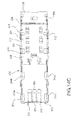
- FIG. 14C is a bottom plan view of the housing of FIG. 14A .
- FIG. 15 is an enlarged detailed view of the front of the shielded housing showing the interior thereof;
- FIG. 16 is the same view as FIG. 15 , but with the lower half of the EMI gasket collar removed for clarity;
- FIG. 17 is the same view as FIG. 16 , but taken from the underside thereof;
- FIG. 18 is a front elevational view of the shield of FIG. 5 ;
- FIG. 19 is a perspective view of a ganged shield with four separate connector receiving bays arranged in an adjacent orientation, and inserted into the opening of a mounting bracket;
- FIG. 20 is the same view as FIG. 19 , but with the mounting bracket removed;
- FIG. 21 is a front elevational view taken from slightly upward angle of the ganged shield of FIG. 20 ;
- FIG. 22 is a view of the underside of the ganged shield of FIG. 21 ;
- FIG. 23 is an enlarged detail view of the interior of one of the bays of the ganged shield of FIG. 20 ;
- FIG. 24 is the same view as FIG. 23 , but taken from an upward angle to show a portion of the interior of one of the connector receiving bays;
- FIG. 24A is a top plan view of one of the internal guides of the shield of FIG. 24 ;
- FIG. 24B is a sectional view of the connector housing baseplate of FIG. 24 , taken along lines B-B thereof;
- FIG. 25 is the same view as FIG. 24 , but taken from the underside thereof;
- FIG. 26 is a perspective view of an embodiment illustrating a ganged shielding housing bay
- FIG. 26A is a sectional view of the assembly of FIG. 26 , taken generally along lines A-A thereof;
- FIG. 27 is the same view as FIG. 26 , but with the connector terminal assemblies, the housing baseplate and fastening nut removed clarity;
- FIG. 28 is a view of the connector assembly of FIG. 27 taken from right side with the right sidewall thereof removed to show the interior of one of the housing bays;
- FIG. 29 is a view of the shield assembly of FIG. 26 mounted to a circuit board and a portion of the sidewall and top wall removed to show a portion of the interior of one of the housing connector-receiving bays with its dual row of connector guides and keys that are formed in the baseplate of the housing;
- FIG. 30 is a front elevational view of the connector assembly of FIG. 27 ;
- FIG. 31 is a perspective view of the shield and an ancillary component, illustrated as a light pipe carrier aligned therewith but spread apart therefrom;
- FIG. 32 is the same view as FIG. 31 but with the light pipe carrier attached to the housing and the housing inserted into a mounting bracket opening;
- FIG. 33 is a perspective view of the upper housing portion of the shield of FIG. 31 illustrating the lanced retaining members formed in the sidewalk thereof;
- FIG. 34 is a detailed sectional view of the lanced retaining member of FIG. 33 , taken along lines 34 - 34 thereof; and,
- FIG. 35 is a front elevational view of the upper housing of FIG. 33 .
- EMI electromagnetic interference
- the connector can be enclosed in a conductive metal shielding shield that has a longitudinal bay in which the connector is housed, and which accommodates a mating plug-style connector inserted into the bay through an opening shield.
- the bay is elongated and it has an open space between the mating face of the connector and the opening of the shield.
- FIG. 1 illustrates a connector assembly 100 that can be provided in a shield.
- the connector assembly 100 takes the form of an insulative connector housing 101 which is illustrated as having two interengaging first and second (or front and rear) pieces, or parts 102 , 103 .
- the connector housing 101 as shown in FIG. 1 has a wide body portion 104 that extends between a rear face 105 and the front face 106 .
- a mating portion 107 that takes the form of an elongated nose portion 108 projects forwardly of the front face 106 and terminates in a mating face 109 .
- the mating face 109 may have one or more circuit card-receiving slots 110 that are formed widthwise in the mating face 109 , with two such slots 110 being shown in FIG. 1 .
- the connector housing 101 has a hollow interior portion 112 that receives a plurality of terminal assemblies 114 that take the form of insulative frames, or wafers, 115 .
- Each such frame 115 contains a plurality of conductive terminals 116 having tail portions 117 projecting out from one edge 118 and contact portions 119 projecting from a second edge 120 of the frame 115 .
- the two edges 118 , 120 are adjacent each other.
- the terminals 116 further include body portions 121 that interconnect the tail and contact portions 117 , 119 together.
- the terminal assembly frames 115 may have openings 123 formed therein in the form of slots that extend along the terminal body portions 121 to expose them to air and thereby affect the terminal impedance.
- the terminal assemblies are held together as a block within the connector housing 101 in a manner such that the terminal tail portions 117 extend out through the bottom of the connector housing 101 and the terminal contact portions 119 extend from the edges 120 of their frames 115 into the housing nose portion 108 .
- the terminal contact portions 119 can be arranged in the frames 115 as pairs of terminals for differential signal transmission, and each pair can be positioned on one side of one of the card-receiving slots 110 .
- the terminals 116 project forwardly from the leading edge 120 of the terminal assembly frames 115 , and portions 124 of the frames 115 extend past the leading edge 120 .
- the terminal contact portions 119 are cantilevered and act as contact beams that deflect away from the slots 110 when a circuit card is inserted therein.
- the nose portion 108 of the connector housing 101 has terminal-receiving cavities 125 ( FIGS. 1 & 2 ) that extend vertically, a preselected distance, above and below centerlines of each slot 110 .
- the connector housing 101 has two pieces 102 , 103 which mate along an irregular mating line 126 that extends upwardly through the sides of the connector housing 101 along a path that extends from the front to the rear of the connector housing 101 .
- a pair of rails 128 and channels 129 are defined in the two pieces 102 , 103 with the rails 128 fitting into the channels 129 .
- Outer ribs 131 may also be formed on the exterior side surfaces of the rear housing part 103 and these ribs 131 are preferably horizontally aligned with the rails 128 to provide reinforcement to the rails 128 , but also to provide a means for positioning the connector subassembly 100 in an exterior housing or shroud as will be described in greater detail to follow.
- FIGS. 4-18 illustrate a shield 200 which is used to house the connector assembly 100 , and provide EMI shielding to it.
- the shield 200 provides a plurality of sidewalk that provide a hollow interior and which substantially envelopes the connector assembly 100 except for a bottom opening 207 (visible in FIG. 7 ) from which the terminal tail portions 117 of the connector project.
- the bottom engagement recess 152 of the connector housing 101 may also contact and engage a fastening nut ( FIG. 8 ) that is used to fasten the external shroud 200 to a circuit board.
- the exterior ribs 131 of the connector housing 101 also wilt preferably frictionally engage the inner sidewalls of the external shroud 200 to provide a means of centering the connector housing 101 within the hollow interior of the external shroud.
- a shield 200 is depicted mounted to an opening of a mounting bracket, or faceplate 10 ′, which engages an EMI gasket collar 270 encircling the shield at its opening 206 .
- the shield 200 provides a port 205 ( FIG. 5 ) that is partially defined by a first side 205 a , a second side 205 b and a third side 205 c . These sides 205 a - c and the baseplate 230 cooperatively define the port 205 that receives the connector assembly 200 .
- the first, second and third side 205 a - c provide a cover 210 that is formed on a single piece of metal.
- the cover 210 could also be formed of two or three pieces joined together but the use of a single piece has been determined to be beneficial from a manufacturing standpoint.
- the faceplate 10 ′ includes a body 11 that defines a first plane and the body 11 has a width and includes a first end 12 that is narrower than the width.
- the body 11 includes a second end 13 and a first tab 14 is folded from the second end 13 so as to define a second plane that is substantially at a right angle to the first plane.
- a second tab 15 is folded from the second end 13 and the second tab 15 defines a third plane that is substantially at a right angle to the first plane.
- the port 205 engages the circuit board 20 ′ and is coupled thereto.
- the connector may include a threaded member 290 , as noted above, which may be an internally threaded member, such as a threaded nut, that is supported by the port 205 and provides a mechanism by which the connector assembly 200 may be fastened to the circuit board 20 ′.
- a screw can be inserted through an aperture 21 ′ also in the circuit board 20 ′, which may include force spreader 22 ′, also in the circuit board so as to engage the threaded member 290 and secure the connector to the board, thus providing additional structural rigidity to the mounted assembly as compared to merely using tails 212 , 252 extending from the port 205 that engage and are soldered to the PCB.
- the threaded member could also have a convention screw-like configuration that extends through the circuit board when the two are joined and engages a nut.
- the port 205 includes three distinct parts: the cover 210 , a baseplate 230 and a rear plate 250 that are coupled together by way of a plurality of engagement tabs.
- the cover 210 may be formed in a U-shape manner, as shown, and the baseplate 230 may be assembled and coupled to the cover 210 via engagement tabs, and then the rear plate 250 may be assembled to the cover 210 and the baseplate 230 and secured with bent tabs so as to form the port 205 .
- the connector housing 101 Prior to completing the assembly, (e.g., before coupling the rear plate 250 ), the connector housing 101 can be inserted into the partially formed port so as to provide an connector assembly that may then be mounted on a circuit board ( FIG. 10 ).
- the cover 210 is generally U-shaped with a top wall and two sidewalk as shown in the illustrated embodiment.
- the cover 210 is formed as a single unit, and it includes a plurality of engagement tabs, 213 and 215 , that are formed along bottom edges thereof. These tabs 213 , 215 are positioned to engage the baseplate 230 to secure the cover 210 and baseplate 230 together.
- the baseplate 230 further is held between the lower tabs 213 , 215 of the cover 210 and front engagement tabs 226 so as to securely couple the cover 210 and baseplate 230 together.
- the baseplate 230 also includes a pair of side panels 230 b that are bent upwardly out of the plane of the baseplate and adjacent the sidewalk of the cover 210 so as to provide overlapping walk that help strengthen the port 205 .
- FIGS. 14A-14C This manner of engagement is shown best in FIGS. 14A-14C where it can be seen that the baseplate 230 , when its side panels 230 b are bent upwardly, can have a general U-shape that is aligned opposite the U-shape of the cover 210 . These side panels 230 b have slots 231 disposed therein that are aligned with the engagement tabs 213 , 215 of the cover 210 .
- the front support tabs 226 of the cover 210 provide a measure of support for the baseplate 230 and engage it by contacting confronting portions of the inner surfaces of the baseplate, while the first shield engagement tabs 213 , 215 extend through the slots 231 and are bent over the baseplate 230 so that they bear against the bottom surfaces thereof.
- the front-most slot 231 is preferably of a longer width than the rearmost slot so as to accommodate, as illustrated more clearly in FIGS. 14A-C , the combined engagement tab-tail combination 215 - 212 as described in more detail below.
- the cover 210 also includes gasket retaining tabs 216 disposed at the front end of the cover 210 . As shown in Figures, especially FIGS. 6 & 14C , these tabs 216 extend through slots on the lower half of the gasket collar 270 and are bent thereupon to retain it in place at the front of the shield. The combination of these engagement tabs and the overlapping side panels allows the cover and the baseplate to be held together in a secure manner.
- the rear plate 250 which has a rear wall 251 , is depicted with has two side panels 253 that extend forwardly from the rear wall 251 and overlap the cover 210 on sides 205 a and 205 c .
- the side panels 253 have slots 255 formed thereon in alignment with the rear edges of the sides 205 b , 205 c .
- the port 205 has a series of engagement tabs 220 that are formed along the rear edges and these tabs 220 are received in and extend through the slots 255 and then are bent over, adjacent to the rear wall 251 .
- the rear plate 250 may also include a support tab 254 that is wider than the tabs 220 which is placed into contact against the inner surface of the side 205 b .
- the cover 210 includes tails 212 that are configured to engage apertures (such as plated vias) in a circuit board so as to electrically couple the shield to ground circuits on the circuit board.
- the baseplate 230 securely holds the threaded member 290 in place to prevent the threaded member 290 from rotating when a mating threaded member is coupled to the threaded member 290 .
- the EMI gasket collar 270 includes a first half 270 a and a second half 270 b that together extend around the perimeter of opening 206 .
- the gasket collar is provided with slender fingers 271 as is known in the art, which are formed as part of the body portion of the gasket half, and provide an outward bow for contacting the walls of an opening in a mounting bracket 10 ′ and free ends that contact the exterior surfaces of the shield sidewalk 205 b . 205 c .
- Engagement tabs 273 are provided at varying locations around the gasket collar 270 and are configured to be received within recesses 218 so that a minimum of space is occupied with still providing a reliable means to fasten the EMI gasket 270 to the edges 206 a , 206 b , 206 c , 206 d of the opening 206 ( FIG. 15 ). These tabs 273 at least preferably provide two points of attachment of the gasket half 270 a , 270 b to the shield and with the top and bottom wider engagement tabs 277 a , 277 b , at least three points of attachment are provided.
- securing tabs 272 extend into apertures 217 that are formed in the shield walls. These tabs 272 are fixed at one end to the gasket collar 270 and are sent inwardly toward the front of the opening 206 , where they terminate in free ends. These free ends 272 a prevent the gasket collar 270 from sliding off the cover 210 in the forward direction, while the tabs 277 a , 277 b which are folded over the front edge of the opening 206 provide a stop for the gasket collar 270 and prevent it from sliding rearwardly away on the port 205 away from the opening 206 , during insertion of the shield 200 into mounting brackets and the like.
- EMI-retaining tabs 216 extend through two apertures 238 in the bottom half 270 b of the gasket 270 and are bent over to hold the gasket 270 in place.
- a single wider tab 277 a , 277 b is shown engaging a recess 218 .
- the wider tab 277 a , 277 b helps secure the base portions 281 of the EMI gasket 270 that extends a full width of edges 206 a , 206 c while multiple smaller tabs are suitable for securing sides 282 , 283 of the gaskets to edges 206 b , 206 d .
- Coincident openings 219 can be formed in both the gasket top half 270 a and the side 205 b so as to receive engagement hooks of the opposing mating connector, if such engagement is desired.
- a module when inserted, it must traverse the passageway provided by the port 205 for a distance before engaging the housing 101 .
- Existing tab designs provided a tab that was susceptible to being bent out of position to a point where it would cease to properly function as a guide. Furthermore, such designs fail to provide a tab that provided a wide support face.
- a first bottom wall 235 is provided that is joined to a second bottom wall 237 by an interconnecting shoulder 236 .
- These first and second bottom wall 235 , 237 are offset, with the first bottom wall 235 configured to be spaced away from a supporting circuit board, while the second wall 237 is positioned closer to the supporting circuit board 20 .
- the front bottom wall 235 has a front edge that aligns with the front edges of the port 205 and completes the perimeter of the opening 206 .
- a series of guides 233 can be formed in the baseplate 230 and extend up from the second wall 237 . The top surfaces of these guides 233 can be aligned with the plane formed by first wall 235 so as to provide additional support for a plug connector as it is inserted into the port 205 . Alternatively, the guides can extend further into the enclosure.
- FIG. 24A shows one of the guide 233 ′ of the enclosure of FIG. 24
- FIGS. 24A &B illustrate the structure of an embodiment of the guides 233
- the guides 233 can be formed by “lancing” the baseplate 230 .
- a lancing process can be used to form a pairs of slits 233 d , which are preferably parallel to each other.
- the slits can extend completely through the thickness of the baseplate 230 .
- Each pair of slits 233 d defines a single guide 233 and the guide may be formed so that it is pushed above second wall 237 of the baseplate 230 .
- the resultant form is rectangular or trapezoidal in configuration as shown.
- the forming of the guide above the plane of the baseplate 233 can result in a slight elongation of the material as well as a slight reduction of its thickness.
- the guide 233 as formed has a body portion with a top surface 233 a (e.g., the support surface) that is interconnected by shoulders 233 b , 233 c to the baseplate 230 .
- each guide 233 is connected to the baseplate 230 at two locations on opposite ends of top surface 233 and is inherently stronger than if formed in the conventional cantilevered manner.
- the guides 233 are shown in an illustrative embodiment of a pattern where all of the guides are aligned together along a common longitudinal axis, and this is shown in FIG.
- the top surfaces of the guides 233 are all aligned with each other and the first bottom wall 235 of the baseplate 230 and further generally lie in a common plane “P”.
- the guides 233 may also be arranged in two rows and may also be arranged in some other pattern on the baseplate 230 .
- a space may be provided between threaded member 290 and the underside of the sub-assembly 202 , which may be a given height t (as shown in FIG. 23 ). This allows a matter connector to be inserted therebetween while a portion of the sub-assembly engages the threaded member 290 .
- FIGS. 19-22 illustrate an embodiment of a shield 200 ′ that has a port array 205 ′ that provides a ganged receptacle connector with distinct openings 206 ′, 206 ′′, 206 ′′′, and 206 ′′′′ so as to provide four ports. Separating the openings are dividing walls 295 , which include first projections 296 that secure the dividing walls 295 to cover 210 ′ and second projections 297 that secure the dividing walls 295 to the baseplate 230 ′.
- the general construction of the port array 205 ′ may be substantially the same as discussed above with respect to port 205 , with the exception of the inclusion of the dividing walls 295 and the increased dimensions of the port array 205 ′ and corresponding cover 210 ′ and baseplate 230 ′.
- EMI gasket while extending across four ganged openings, is still a largely a two-piece design. While such a construction is not required, the benefits of the design include reducing piece count.
- a top engagement tab 296 on the top edges of each of the dividing walls 295 are received within respective openings 286 formed in a retaining plate 285 formed as part of the EMI gasket upper half 270 a ′ and which secures it to the cover 210 ′.
- a similar feature is provided for securing the lower EMI gasket half 270 b ′ to the baseplate 230 ′ in the form of a second EMI tab 298 that engages the EMI gasket half 270 b′.
- the dividing wall 295 further may include support tabs 288 , 289 that are used to support the sub-assembly positioned in each of the ganged connectors.
- the tabs may be bent in alternating first and second directions.
- the divider further includes a plurality of board-mounting tails 299 .
- a tail may be positioned between two support tabs 288 and/or between two support tabs 289 .
- the dividing walls 295 may further include tabs that engage the rear plate 250 ′ in a manner similar to how the tabs 296 engage the cover 210 ′.
- additional connector engagement tabs 214 a ′, 214 b ′ are formed along the lower edges thereof and bent in opposite direction, as shown in FIG. 22 so as to contact the connector housings placed in adjacent bays.
- the cover and the baseplate and the rear plate, in combination with N ⁇ 1 dividers can provide a ganged connector configured to receive N plugs.
- a 1 ⁇ 2 configuration, a 1 ⁇ 3 or a larger 1 ⁇ 5+ configuration is possible.
- the 1 ⁇ 4 connector will be the maximum desired size because it provides four receptacles for connectors while still fitting on a standard PCI card.
- the enclosure may be further configured to hold a fastening nut in place so that it may be engaged with a screw or bolt or the like from underneath the circuit hoard 20 ′.
- the baseplate 230 of the shield 200 is provided with a means in engaging the fastening nut 290 .
- This fastener-engagement means takes the form of a slot, or opening, 2017 that is preferably formed in alignment with the connector housing lower engagement recess 152 , which also accommodates the nut 290 .
- the baseplate 230 has three tabs 2019 formed therewith that are disposed there on so as to confront three flat surfaces, or fiats of the nut.
- these retention tabs 2019 cooperate with the flat surfaces of the connector housing 2010 arranged in half-hexagon to effectively capture the nut 2010 in place. Additionally, because the tabs extend beneath the nut 2010 and between it and the surface of the circuit board, the tables 2019 act together as would a lock washer. The placement of such a washer would be difficult given the environment in which the shields and connectors are used and the tabs eliminate the need in such washers. Although in this embodiment, the bottom engagement recess 152 of the connector 100 is shown as multi-faceted (having multiple interconnected flat sides that mike contact with opposing flat surfaces on the fastening nut), such surfaces are not required. Additionally, some of the tabs 2019 a may be bent above the opening 2017 so that the nut 290 may be inserted into the assembly before the connector housing 101 is inserted into the enclosure 200 and so the nut 290 is retained in place in it opening.
- the baseplate 230 of the shroud 200 may be further lanced and formed to provide a series of raised elements, or guides, 233 that may be aligned in a pattern in each port provided by the port array.
- the pattern may be a pair of longitudinal rows (as shown in FIGS. 27-31 ) or a single row (as shown in FIGS. 24 and 25 ) or some other desirable pattern.
- the baseplate 230 can provide a plurality of patterns with each pattern aligned with one of the passageways formed by the shield.
- the guides 233 can be positioned so as to properly direct an opposing connector or module into alignment with the card-receiving slots 125 of the connector housing 101 .
- the pattern is repeated in each port so as to ensure consistent control and alignment of the inserted plug.
- these guides extend from proximate the housing opening to the mating face and can be positioned underneath it) of the interior connector 100 .
- One such guide acts as a key 266 is disposed proximate to the housing opening and arranged transversely to a longitudinal axis of the housing opening so as to provide a polarizing, or keying, feature that will fit a recess formed on the underside of an opposing plug connector.
- This key 266 is shown disposed on the bottom wall of the housing, but it will be understood that it may be formed on any of the sides of the housing provided it can engage a mating connector.
- This key 266 is formed from the material between two slits 266 d that are formed in the baseplate 230 . That material defines a body portion 266 a that is connected to the baseplate 230 by two end or leg portions 266 b , 266 c . Its two points of connection, as well as its widthwise orientation within the housing bay, provide the key with a measure of strength that will resist forces that may be generated by stubbing and initial misalignment.
- FIGS. 31-35 illustrate an additional embodiment of a shield 300 in which the sidewalls 300 are lanced to provide support members in ancillary components.
- the shield 300 includes a cover 302 with a top wall 304 and two sidewalls 306 , shown formed as a single piece.
- the sidewalls 306 each include a pair of retaining members 310 disposed thereon and spread apart from each other.
- the retaining members 310 can be arranged so as to form a horizontal line.
- retaining members 310 extend outwardly (out of plane) from the sidewalk 306 to provide projections that, as depicted, may be engaged by opening in auxiliary member 312 .
- auxiliary member 312 can support an array 314 of light pipes 316 that are shown in FIG. 31 as supported on a carrier 318 .
- the carrier 318 has a top plate portion 319 with light pipe supports 320 integrally formed therewith with it along its top plate portion 319 and further includes a series of clips 322 that extend downwardly from the top plate portion 319 .
- clips 322 are generally square in configuration and have a central opening 323 disposed therein. The central opening 323 fits over the retaining member 310 so that the lower edge 323 a of each clip opening 323 lies beneath and in opposition to a lower edge 329 of the retaining member 310 .
- the retaining member 310 may advantageously be formed using a lancing process where a slit 311 is formed in the sidewall 306 that extends completely through the sidewall 306 .
- the lower edge 329 of the retaining members 310 which lie adjacent to slit 311 , is then pressed outwardly to create outwardly projecting body portion projections 324 with outer surfaces 324 a and continuous sides 325 that are attached to the housing sidewalk 306 .
- the lower edge 329 of the retaining member can be a “hard” edge, meaning it lies adjacent to slot 311 and can provide a right angle. As such, it is capable of reliably engaging the lower edge 323 a of the clip opening 323 and thus helps secure the clip 322 in place.
- the retaining member lower edge 329 is connected at both its ends to the housing sidewalls, as are the aforementioned guides and keys, and it is incapable of extending over the top of the clip opening lower edge 323 a and the clip 322 itself because its lower edge serves as a stop.
- the retaining members 310 of the present invention not only provide reliable retention to the carrier 318 , but also provide easy removal thereof, which is accomplished by lifting the lower edge 323 a of the clip 322 up over the lower edge 329 of the retaining member 310 .
- the attachment of the lower edge 329 at its ends reduces the possibility that the retaining member will then interfere with the removal of the carrier 318 .
Abstract
Description
Claims (8)
Priority Applications (1)
| Application Number | Priority Date | Filing Date | Title |
|---|---|---|---|
| US13/705,751 US8740646B2 (en) | 2008-09-09 | 2012-12-05 | Connector having a shield mounted on a circuit board and extending through an aperture in a bracket |
Applications Claiming Priority (10)
| Application Number | Priority Date | Filing Date | Title |
|---|---|---|---|
| US9545008P | 2008-09-09 | 2008-09-09 | |
| US11074808P | 2008-11-03 | 2008-11-03 | |
| US11747008P | 2008-11-24 | 2008-11-24 | |
| US15357909P | 2009-02-18 | 2009-02-18 | |
| US17103709P | 2009-04-20 | 2009-04-20 | |
| US17106609P | 2009-04-20 | 2009-04-20 | |
| US17095609P | 2009-04-20 | 2009-04-20 | |
| PCT/US2009/056298 WO2010030619A2 (en) | 2008-09-09 | 2009-09-09 | Shield with integrated mating connector guides |
| US201113062973A | 2011-05-19 | 2011-05-19 | |
| US13/705,751 US8740646B2 (en) | 2008-09-09 | 2012-12-05 | Connector having a shield mounted on a circuit board and extending through an aperture in a bracket |
Related Parent Applications (3)
| Application Number | Title | Priority Date | Filing Date |
|---|---|---|---|
| US13/062,973 Continuation US8342881B2 (en) | 2008-09-09 | 2009-09-09 | Shield with integrated mating connector guides |
| PCT/US2009/056298 Continuation WO2010030619A2 (en) | 2008-09-09 | 2009-09-09 | Shield with integrated mating connector guides |
| US201113062973A Continuation | 2008-09-09 | 2011-05-19 |
Publications (2)
| Publication Number | Publication Date |
|---|---|
| US20130189876A1 US20130189876A1 (en) | 2013-07-25 |
| US8740646B2 true US8740646B2 (en) | 2014-06-03 |
Family
ID=41165437
Family Applications (18)
| Application Number | Title | Priority Date | Filing Date |
|---|---|---|---|
| US13/062,360 Active 2029-11-02 US8439704B2 (en) | 2008-09-09 | 2009-09-09 | Horizontally configured connector with edge card mounting structure |
| US13/063,010 Active US8449312B2 (en) | 2008-09-09 | 2009-09-09 | Housing with a plurality of wafers and having a nose portion with engagement members |
| US13/062,977 Active US8162675B2 (en) | 2008-09-09 | 2009-09-09 | Connector shield with integrated fastening arrangement |
| US13/063,008 Active US8226441B2 (en) | 2008-09-09 | 2009-09-09 | Connector with improved manufacturability |
| US13/062,973 Active US8342881B2 (en) | 2008-09-09 | 2009-09-09 | Shield with integrated mating connector guides |
| US13/062,984 Active 2030-04-03 US8465302B2 (en) | 2008-09-09 | 2009-09-09 | Connector with impedance tuned terminal arrangement |
| US13/062,248 Active US8187019B2 (en) | 2008-09-09 | 2009-09-09 | Connector with integrated latch assembly |
| US13/062,986 Active US8753145B2 (en) | 2008-09-09 | 2009-09-09 | Guide frame with two columns connected by cross pieces defining an opening with retention members |
| US13/062,240 Active US8241045B2 (en) | 2008-09-09 | 2009-09-09 | Horizontally configured connector |
| US13/423,910 Active US8460033B2 (en) | 2008-09-09 | 2012-03-19 | Connector shield with integrated fastening arrangement |
| US13/463,515 Active US8414324B2 (en) | 2008-09-09 | 2012-05-03 | Connector with integrated latch assembly |
| US13/532,985 Active 2029-10-05 US8678839B2 (en) | 2008-09-09 | 2012-06-26 | Horizontally configured connector |
| US13/534,104 Active US8597055B2 (en) | 2008-09-09 | 2012-06-27 | Electrical connector |
| US13/612,039 Active US8573997B2 (en) | 2008-09-09 | 2012-09-12 | Multi-plugging connector system |
| US13/705,751 Active US8740646B2 (en) | 2008-09-09 | 2012-12-05 | Connector having a shield mounted on a circuit board and extending through an aperture in a bracket |
| US14/187,443 Active US8821168B2 (en) | 2008-09-09 | 2014-02-24 | Horizontally configured connector |
| US14/340,002 Active US9461392B2 (en) | 2008-09-09 | 2014-07-24 | Vertically configured connector |
| US15/251,669 Active US9748713B2 (en) | 2008-09-09 | 2016-08-30 | Horizontally configured connector |
Family Applications Before (14)
| Application Number | Title | Priority Date | Filing Date |
|---|---|---|---|
| US13/062,360 Active 2029-11-02 US8439704B2 (en) | 2008-09-09 | 2009-09-09 | Horizontally configured connector with edge card mounting structure |
| US13/063,010 Active US8449312B2 (en) | 2008-09-09 | 2009-09-09 | Housing with a plurality of wafers and having a nose portion with engagement members |
| US13/062,977 Active US8162675B2 (en) | 2008-09-09 | 2009-09-09 | Connector shield with integrated fastening arrangement |
| US13/063,008 Active US8226441B2 (en) | 2008-09-09 | 2009-09-09 | Connector with improved manufacturability |
| US13/062,973 Active US8342881B2 (en) | 2008-09-09 | 2009-09-09 | Shield with integrated mating connector guides |
| US13/062,984 Active 2030-04-03 US8465302B2 (en) | 2008-09-09 | 2009-09-09 | Connector with impedance tuned terminal arrangement |
| US13/062,248 Active US8187019B2 (en) | 2008-09-09 | 2009-09-09 | Connector with integrated latch assembly |
| US13/062,986 Active US8753145B2 (en) | 2008-09-09 | 2009-09-09 | Guide frame with two columns connected by cross pieces defining an opening with retention members |
| US13/062,240 Active US8241045B2 (en) | 2008-09-09 | 2009-09-09 | Horizontally configured connector |
| US13/423,910 Active US8460033B2 (en) | 2008-09-09 | 2012-03-19 | Connector shield with integrated fastening arrangement |
| US13/463,515 Active US8414324B2 (en) | 2008-09-09 | 2012-05-03 | Connector with integrated latch assembly |
| US13/532,985 Active 2029-10-05 US8678839B2 (en) | 2008-09-09 | 2012-06-26 | Horizontally configured connector |
| US13/534,104 Active US8597055B2 (en) | 2008-09-09 | 2012-06-27 | Electrical connector |
| US13/612,039 Active US8573997B2 (en) | 2008-09-09 | 2012-09-12 | Multi-plugging connector system |
Family Applications After (3)
| Application Number | Title | Priority Date | Filing Date |
|---|---|---|---|
| US14/187,443 Active US8821168B2 (en) | 2008-09-09 | 2014-02-24 | Horizontally configured connector |
| US14/340,002 Active US9461392B2 (en) | 2008-09-09 | 2014-07-24 | Vertically configured connector |
| US15/251,669 Active US9748713B2 (en) | 2008-09-09 | 2016-08-30 | Horizontally configured connector |
Country Status (6)
| Country | Link |
|---|---|
| US (18) | US8439704B2 (en) |
| JP (6) | JP5548199B2 (en) |
| CN (20) | CN103001065B (en) |
| MY (3) | MY159007A (en) |
| TW (9) | TWM395940U (en) |
| WO (9) | WO2010030616A1 (en) |
Cited By (6)
| Publication number | Priority date | Publication date | Assignee | Title |
|---|---|---|---|---|
| US20140199862A1 (en) * | 2013-01-11 | 2014-07-17 | Molex Incorporated | Compliant Pin With Improved Insertion Capabilities |
| US9391407B1 (en) * | 2015-06-12 | 2016-07-12 | Tyco Electronics Corporation | Electrical connector assembly having stepped surface |
| US9686877B2 (en) | 2014-04-21 | 2017-06-20 | Yazaki Corporation | Locking structure between member to be supported and supporting body |
| US10276995B2 (en) * | 2017-01-23 | 2019-04-30 | Foxconn Interconnect Technology Limited | Electrical adaptor for different plug module and electrical assembly having the same |
| US10454203B2 (en) | 2018-03-06 | 2019-10-22 | Te Connectivity Corporation | Receptacle connector of an electrical connector system |
| US11212949B2 (en) | 2019-07-29 | 2021-12-28 | Samsung Electronics Co., Ltd. | Solid state drive device including a gasket |
Families Citing this family (224)
| Publication number | Priority date | Publication date | Assignee | Title |
|---|---|---|---|---|
| US8167638B2 (en) * | 2007-06-12 | 2012-05-01 | Panduit Corp. | Multi-position quick release plug cassette assembly |
| WO2010030616A1 (en) * | 2008-09-09 | 2010-03-18 | Molex Incorporated | Connector with integrated latch assembly |
| US8506317B2 (en) * | 2008-12-04 | 2013-08-13 | 3M Innovative Properties Company | Method, system and devices for interconnecting a plurality of devices |
| WO2010085465A1 (en) * | 2009-01-20 | 2010-07-29 | Molex Incorporated | Plug connector with external emi shielding capability |
| US9011177B2 (en) | 2009-01-30 | 2015-04-21 | Molex Incorporated | High speed bypass cable assembly |
| CN102405564B (en) * | 2009-02-18 | 2014-09-03 | 莫列斯公司 | Vertical connector for a printed circuit board |
| US9028281B2 (en) | 2009-11-13 | 2015-05-12 | Amphenol Corporation | High performance, small form factor connector |
| CN201639088U (en) * | 2010-01-25 | 2010-11-17 | 富士康(昆山)电脑接插件有限公司 | Cable connector assembly |
| WO2011100740A2 (en) * | 2010-02-15 | 2011-08-18 | Molex Incorporated | Differentially coupled connector |
| TWM430018U (en) * | 2010-03-19 | 2012-05-21 | Molex Inc | Cable connector and connector circuit board spacer |
| US8007318B1 (en) * | 2010-03-22 | 2011-08-30 | Tyco Electronics Corporation | Shielded integrated connector module |
| WO2011140438A2 (en) | 2010-05-07 | 2011-11-10 | Amphenol Corporation | High performance cable connector |
| US8734187B2 (en) * | 2010-06-28 | 2014-05-27 | Fci | Electrical connector with ground plates |
| JP2012013913A (en) * | 2010-06-30 | 2012-01-19 | Suncall Corp | Optical connector |
| US8585426B2 (en) * | 2010-07-27 | 2013-11-19 | Fci Americas Technology Llc | Electrical connector including latch assembly |
| CN201797100U (en) * | 2010-08-18 | 2011-04-13 | 富士康(昆山)电脑接插件有限公司 | Cable connector assembly |
| US8573853B2 (en) * | 2010-08-23 | 2013-11-05 | Tyco Electronics Corporation | Plug assembly |
| US8062073B1 (en) * | 2010-09-02 | 2011-11-22 | Tyco Electronics Corporation | Receptacle connector |
| CN102403605B (en) * | 2010-09-15 | 2014-09-24 | 富士康(昆山)电脑接插件有限公司 | Cable connector component |
| WO2012103107A2 (en) * | 2011-01-24 | 2012-08-02 | Molex Incorporated | Connector latch actuator with improved torsional resistance |
| CN102646898B (en) * | 2011-02-18 | 2014-10-29 | 富士康(昆山)电脑接插件有限公司 | Electrical connector assembly |
| CN102646900B (en) * | 2011-02-18 | 2014-08-27 | 富士康(昆山)电脑接插件有限公司 | Electrical connector assembly |
| CN102646899B (en) * | 2011-02-18 | 2015-04-01 | 富士康(昆山)电脑接插件有限公司 | Electrical connector assembly |
| CN102651521B (en) * | 2011-02-25 | 2014-09-24 | 富士康(昆山)电脑接插件有限公司 | Electric connector assembly |
| US8935849B2 (en) * | 2011-03-10 | 2015-01-20 | Fci Americas Technology Llc | Method for mounting a cable connector onto a panel |
| US8727793B2 (en) * | 2011-03-11 | 2014-05-20 | Cisco Technology, Inc. | Optical module design in an SFP form factor to support increased rates of data transmission |
| CN102802386B (en) * | 2011-05-25 | 2016-04-20 | 莱尔德电子材料(深圳)有限公司 | Electromagnetic interference shield assembly |
| US8597052B2 (en) * | 2011-07-13 | 2013-12-03 | Tyco Electronics Corporation | Grounding structures for header and receptacle assemblies |
| US8591260B2 (en) * | 2011-07-13 | 2013-11-26 | Tyco Electronics Corporation | Grounding structures for header and receptacle assemblies |
| JP6242792B2 (en) * | 2011-08-08 | 2017-12-06 | モレックス エルエルシー | Connector with tuning channel |
| CN202259790U (en) * | 2011-08-19 | 2012-05-30 | 富士康(昆山)电脑接插件有限公司 | Electric connector |
| EP2748898B1 (en) * | 2011-10-05 | 2017-07-05 | Senko Advanced Components, Inc. | Latching connector with remote release |
| US20130094153A1 (en) * | 2011-10-13 | 2013-04-18 | Finisar Corporation | Electromagnetic radiation shielding on a pci express card |
| TWM461182U (en) * | 2011-11-08 | 2013-09-01 | Molex Inc | Connector and connector system |
| CN103091798A (en) * | 2011-11-08 | 2013-05-08 | 鸿富锦精密工业(深圳)有限公司 | Connector module |
| CN102522655A (en) * | 2011-12-08 | 2012-06-27 | 华为技术有限公司 | Connector, interface system, connector group and cable plug |
| EP2795730B1 (en) | 2011-12-23 | 2017-12-20 | Intel Corporation | High bandwidth connector for internal and external io interfaces |
| JP2013138110A (en) * | 2011-12-28 | 2013-07-11 | Honda Tsushin Kogyo Co Ltd | Cage for electric connector |
| US8979558B2 (en) * | 2012-03-12 | 2015-03-17 | Fci Americas Technology Llc | Interposer assembly |
| CN102637973B (en) * | 2012-03-23 | 2014-03-12 | 中航光电科技股份有限公司 | Rectangular connector |
| CN202949055U (en) * | 2012-05-01 | 2013-05-22 | 莫列斯公司 | Connector |
| TWI555274B (en) | 2012-05-03 | 2016-10-21 | Molex Inc | Connector |
| DE102012104549B4 (en) | 2012-05-25 | 2016-07-28 | Weetech Gmbh | Variable connector of a connector |
| CN103457109B (en) * | 2012-05-31 | 2016-06-08 | 富士康(昆山)电脑接插件有限公司 | Wire and cable connector |
| WO2013185305A1 (en) * | 2012-06-13 | 2013-12-19 | 华为技术有限公司 | Connector and server |
| CN103515793A (en) | 2012-06-16 | 2014-01-15 | 富士康(昆山)电脑接插件有限公司 | Electric connector and printed circuit board contained in electric connector |
| EP2680373A1 (en) * | 2012-06-27 | 2014-01-01 | Siemens Aktiengesellschaft | Module for system cabling |
| US9246262B2 (en) | 2012-08-06 | 2016-01-26 | Fci Americas Technology Llc | Electrical connector including latch assembly with pull tab |
| CN103579798B (en) * | 2012-08-07 | 2016-08-03 | 泰科电子(上海)有限公司 | Electric connector and conducting terminal assembly thereof |
| US9831588B2 (en) | 2012-08-22 | 2017-11-28 | Amphenol Corporation | High-frequency electrical connector |
| GB2505646A (en) * | 2012-09-05 | 2014-03-12 | Eaton Ind France Sas | Connector for an uninterruptible power supply |
| WO2014043426A1 (en) * | 2012-09-17 | 2014-03-20 | 3M Innovative Properties Company | Dual pull tab |
| TWI484705B (en) * | 2012-09-28 | 2015-05-11 | Molex Inc | Electrical connector |
| US8979553B2 (en) * | 2012-10-25 | 2015-03-17 | Molex Incorporated | Connector guide for orienting wires for termination |
| CN103794953A (en) * | 2012-10-30 | 2014-05-14 | 华为技术有限公司 | Connector |
| US8636544B1 (en) * | 2012-11-28 | 2014-01-28 | Tyco Electronics Corporation | Plug connector and receptacle assembly for mating with the same |
| CN103887655B (en) * | 2012-12-19 | 2016-08-10 | 富士康(昆山)电脑接插件有限公司 | Adapter |
| CN103887645B (en) * | 2012-12-19 | 2016-10-26 | 富士康(昆山)电脑接插件有限公司 | Adapter |
| TWI548157B (en) * | 2013-01-28 | 2016-09-01 | 鴻海精密工業股份有限公司 | Connector |
| US8845364B2 (en) * | 2013-02-27 | 2014-09-30 | Molex Incorporated | High speed bypass cable for use with backplanes |
| JP6170573B2 (en) * | 2013-02-27 | 2017-07-26 | モレックス エルエルシー | Small connector system |
| US9142921B2 (en) | 2013-02-27 | 2015-09-22 | Molex Incorporated | High speed bypass cable for use with backplanes |
| CN104022402B (en) * | 2013-03-01 | 2017-02-08 | 富士康(昆山)电脑接插件有限公司 | Electric connector |
| CN104022404B (en) * | 2013-03-01 | 2017-05-24 | 富士康(昆山)电脑接插件有限公司 | Electric connector |
| EP2965386A4 (en) | 2013-03-04 | 2017-01-18 | 3M Innovative Properties Company | Electrical interconnection system and electrical connectors for the same |
| US9197019B2 (en) * | 2013-03-14 | 2015-11-24 | Hubbell Incorporated | Grounding clip for electrical components |
| US9093794B2 (en) * | 2013-03-28 | 2015-07-28 | Cisco Technology, Inc. | Spoon shaped electromagnetic interference fingers |
| TWM462985U (en) | 2013-04-09 | 2013-10-01 | Molex Taiwan Ltd | Electrical connection device |
| CN104124550B (en) | 2013-04-26 | 2016-12-28 | 富士康(昆山)电脑接插件有限公司 | Electric connector |
| CN105612668B (en) * | 2013-07-08 | 2018-06-12 | 莫列斯有限公司 | Connector, pin connector and clasp connector |
| CN105393411B (en) | 2013-07-10 | 2018-07-17 | 莫列斯有限公司 | Low clearance clasp connector |
| US8998651B2 (en) * | 2013-07-10 | 2015-04-07 | Bellwether Electronic Corp. | Plug having a body with a plurality of bars in a first direction and a second direction each with a channel to accommodate a terminal |
| US9385487B2 (en) | 2013-07-11 | 2016-07-05 | Hon Hai Precision Industry Co., Ltd. | Active plug connector and method for assembling the same |
| CN104283012B (en) * | 2013-07-11 | 2016-08-31 | 富士康(昆山)电脑接插件有限公司 | Active plug connector |
| CN104283067B (en) * | 2013-07-11 | 2019-07-12 | 冯辉舜 | High-speed electric connector assembly and circuit board coupled with same |
| CN104347973B (en) * | 2013-08-01 | 2016-09-28 | 富士康(昆山)电脑接插件有限公司 | Connector assembly |
| JP6208878B2 (en) * | 2013-09-04 | 2017-10-04 | モレックス エルエルシー | Connector system with cable bypass |
| CN104466442B (en) * | 2013-09-13 | 2017-09-26 | 至良科技股份有限公司 | Terminal plate group and the electric connector for including the terminal plate group |
| TWI520451B (en) * | 2013-09-27 | 2016-02-01 | 傳承光電股份有限公司 | Connector |
| US9054432B2 (en) * | 2013-10-02 | 2015-06-09 | All Best Precision Technology Co., Ltd. | Terminal plate set and electric connector including the same |
| CN104716507B (en) * | 2013-12-11 | 2018-08-31 | 富士康(昆山)电脑接插件有限公司 | Connector and its component |
| US9214768B2 (en) * | 2013-12-17 | 2015-12-15 | Topconn Electronic (Kunshan) Co., Ltd. | Communication connector and transmission module thereof |
| CN105981229B (en) * | 2013-12-20 | 2019-10-18 | 莫列斯有限公司 | Connector with the terminal beam portion being adjusted |
| US9905975B2 (en) | 2014-01-22 | 2018-02-27 | Amphenol Corporation | Very high speed, high density electrical interconnection system with edge to broadside transition |
| CN104882703B (en) * | 2014-02-28 | 2017-09-05 | 凡甲电子(苏州)有限公司 | Electric connector |
| US20170045994A1 (en) * | 2014-02-28 | 2017-02-16 | Beyond Twenty Ltd. | Electronic vaporiser system |
| CN103840300A (en) * | 2014-03-10 | 2014-06-04 | 姚广宇 | Crystal head capable of being repeatedly used |
| EP3134945B1 (en) | 2014-04-23 | 2019-06-12 | TE Connectivity Corporation | Electrical connector with shield cap and shielded terminals |
| CN105098416B (en) * | 2014-05-23 | 2017-08-08 | 凡甲电子(苏州)有限公司 | Electric connector |
| JP6401968B2 (en) * | 2014-08-19 | 2018-10-10 | ホシデン株式会社 | Connector and connector manufacturing method |
| US10522958B2 (en) | 2014-09-26 | 2019-12-31 | Hewlett Packard Enterprise Development Lp | Receptacle for connecting a multi-lane or one-lane cable |
| US9468103B2 (en) | 2014-10-08 | 2016-10-11 | Raytheon Company | Interconnect transition apparatus |
| US10651582B2 (en) * | 2014-11-03 | 2020-05-12 | 3M Innovative Properties Company | Connector |
| CN107112696B (en) | 2014-11-12 | 2020-06-09 | 安费诺有限公司 | Very high speed, high density electrical interconnect system with impedance control in the mating region |
| CN107535044B (en) | 2014-11-21 | 2019-12-10 | 安费诺公司 | Mating backplane for high speed, high density electrical connectors |
| JP6009528B2 (en) * | 2014-12-18 | 2016-10-19 | 住友電装株式会社 | Charging inlet |
| US9660333B2 (en) | 2014-12-22 | 2017-05-23 | Raytheon Company | Radiator, solderless interconnect thereof and grounding element thereof |
| TWI710183B (en) | 2015-01-11 | 2020-11-11 | 美商莫仕有限公司 | Circuit board bypass assembly and its components |
| WO2016112384A1 (en) | 2015-01-11 | 2016-07-14 | Molex, Llc | Wire to board connectors suitable for use in bypass routing assemblies |
| US10270209B2 (en) | 2015-02-10 | 2019-04-23 | Molex, Llc | Cable connector |
| TWI580124B (en) * | 2015-02-16 | 2017-04-21 | 慶良電子股份有限公司 | Electrical connector |
| US10741963B2 (en) | 2015-02-27 | 2020-08-11 | Hewlett Packard Enterprise Development Lp | Cable assembly with conjoined one-lane cable assemblies |
| FR3033542B1 (en) * | 2015-03-09 | 2017-07-07 | Aeraccess | ROTARY WING DRONE EQUIPPED WITH REMOVABLE ARMS |
| US9615492B2 (en) | 2015-04-16 | 2017-04-04 | International Business Machines Corporation | Electromagnetic gaskets for a cable connection |
| US10389068B2 (en) | 2015-04-29 | 2019-08-20 | Hewlett Packard Enterprise Development Lp | Multiple cable housing assembly |
| CN204696373U (en) * | 2015-04-30 | 2015-10-07 | 泰科电子(上海)有限公司 | Connector |
| CN107548480B (en) | 2015-05-04 | 2020-08-11 | 莫列斯有限公司 | Computing device employing bypass component |
| CN106299746B (en) | 2015-05-22 | 2019-07-26 | 富士康(昆山)电脑接插件有限公司 | The program down-loading method of electric connector and electric connector |
| US9397444B1 (en) * | 2015-06-01 | 2016-07-19 | Dinkle Enterprise Co., Ltd. | Terminal block wiring device |
| US9583851B2 (en) * | 2015-06-11 | 2017-02-28 | Lenovo Enterprise Solutions (Singapore) Pte. Ltd. | Orthogonal card edge connector |
| CN108701922B (en) | 2015-07-07 | 2020-02-14 | Afci亚洲私人有限公司 | Electrical connector |
| US10141676B2 (en) | 2015-07-23 | 2018-11-27 | Amphenol Corporation | Extender module for modular connector |
| US9484673B1 (en) * | 2015-08-17 | 2016-11-01 | All Best Precision Technology Co., Ltd. | Signal terminal of vertical bilayer electrical connector |
| CN111834815B (en) | 2015-09-23 | 2022-04-01 | 莫列斯有限公司 | Socket assembly |
| US9780458B2 (en) | 2015-10-13 | 2017-10-03 | Raytheon Company | Methods and apparatus for antenna having dual polarized radiating elements with enhanced heat dissipation |
| TWM525568U (en) | 2015-11-12 | 2016-07-11 | 宣德科技股份有限公司 | Electrical connector |
| US10424856B2 (en) | 2016-01-11 | 2019-09-24 | Molex, Llc | Routing assembly and system using same |
| WO2017123614A1 (en) | 2016-01-11 | 2017-07-20 | Molex, Llc | Cable connector assembly |
| WO2017127513A1 (en) | 2016-01-19 | 2017-07-27 | Molex, Llc | Integrated routing assembly and system using same |
| FR3051125B1 (en) * | 2016-05-12 | 2018-06-15 | Gilson Sas | SUPPORTING CONES HOLDER HOUSING FOR PIPETTING SYSTEM |
| CN115663515A (en) * | 2016-05-16 | 2023-01-31 | 莫列斯有限公司 | Socket and connector assembly |
| TWI790785B (en) | 2016-05-31 | 2023-01-21 | 美商安芬諾股份有限公司 | Electrical termination, a cable assembly and a method for terminating a cable |
| CN109155491B (en) | 2016-06-01 | 2020-10-23 | 安费诺Fci连接器新加坡私人有限公司 | High speed electrical connector |
| USD816473S1 (en) * | 2016-08-10 | 2018-05-01 | Mellanox Technologies, Ltd. | Edge retainer for a printed circuit card |
| TWI790798B (en) | 2016-08-23 | 2023-01-21 | 美商安芬諾股份有限公司 | Connector configurable for high performance |
| CN115189187A (en) | 2016-10-19 | 2022-10-14 | 安费诺有限公司 | Flexible shielding piece and electric connector |
| CN106657729A (en) * | 2016-10-27 | 2017-05-10 | 努比亚技术有限公司 | Mobile terminal and dual-camera device |
| US9859640B1 (en) | 2016-11-14 | 2018-01-02 | Te Connectivity Corporation | Electrical connector with plated signal contacts |
| US11152729B2 (en) * | 2016-11-14 | 2021-10-19 | TE Connectivity Services Gmbh | Electrical connector and electrical connector assembly having a mating array of signal and ground contacts |
| US10581177B2 (en) | 2016-12-15 | 2020-03-03 | Raytheon Company | High frequency polymer on metal radiator |
| US11088467B2 (en) | 2016-12-15 | 2021-08-10 | Raytheon Company | Printed wiring board with radiator and feed circuit |
| US10541461B2 (en) | 2016-12-16 | 2020-01-21 | Ratheon Company | Tile for an active electronically scanned array (AESA) |
| US10490952B2 (en) * | 2017-01-16 | 2019-11-26 | Te Connectivity Corporation | Receptacle cage member having locating features |
| US9923309B1 (en) * | 2017-01-27 | 2018-03-20 | Te Connectivity Corporation | PCB connector footprint |
| US10404014B2 (en) * | 2017-02-17 | 2019-09-03 | Fci Usa Llc | Stacking electrical connector with reduced crosstalk |
| TWI612886B (en) * | 2017-03-08 | 2018-01-21 | 啓碁科技股份有限公司 | Electronic device and shielding structure thereof |
| TWI635660B (en) | 2017-04-06 | 2018-09-11 | 技嘉科技股份有限公司 | Connector cover module |
| TWI771263B (en) * | 2017-05-17 | 2022-07-11 | 美商莫仕有限公司 | Socket and Connector Assemblies |
| TWI755396B (en) * | 2017-05-17 | 2022-02-21 | 美商莫仕有限公司 | Socket and Connector Assemblies |
| US11189946B2 (en) | 2017-06-26 | 2021-11-30 | Fci Connectors Dongguan Ltd. | Compact combination connector |
| TWI790268B (en) | 2017-08-03 | 2023-01-21 | 美商安芬諾股份有限公司 | Connector for low loss interconnection system and electronic system comprising the same |
| US10361485B2 (en) | 2017-08-04 | 2019-07-23 | Raytheon Company | Tripole current loop radiating element with integrated circularly polarized feed |
| WO2019084717A1 (en) | 2017-10-30 | 2019-05-09 | Amphenol Fci Asia Pte Ltd | Low crosstalk card edge connector |
| CN109787000B (en) * | 2017-11-11 | 2021-11-19 | 富士康(昆山)电脑接插件有限公司 | Double-sided socket connector and electrical system thereof |
| KR102433376B1 (en) | 2017-11-21 | 2022-08-18 | 몰렉스 엘엘씨 | Key-coupled input/output connectors |
| USD840344S1 (en) * | 2017-11-22 | 2019-02-12 | Molex, Llc | Connector receptacle |
| USD853332S1 (en) * | 2017-11-22 | 2019-07-09 | Molex, Llc | Connector receptable |
| USD840345S1 (en) * | 2017-11-22 | 2019-02-12 | Molex, Llc | Connector receptacle |
| USD840343S1 (en) * | 2017-11-22 | 2019-02-12 | Molex, Llc | Connector receptacle |
| US10601181B2 (en) | 2017-12-01 | 2020-03-24 | Amphenol East Asia Ltd. | Compact electrical connector |
| US10777921B2 (en) | 2017-12-06 | 2020-09-15 | Amphenol East Asia Ltd. | High speed card edge connector |
| CN108173033B (en) * | 2018-01-02 | 2024-01-30 | 欧品电子(昆山)有限公司 | Sheet-type needle seat and signal terminal assembly |
| CN108183349B (en) * | 2018-01-02 | 2024-03-29 | 欧品电子(昆山)有限公司 | High-density connector and sheet-type needle seat |
| US10630010B2 (en) | 2018-01-10 | 2020-04-21 | Te Connectivity Corporation | Stacked dual connector system |
| US10355420B1 (en) * | 2018-01-10 | 2019-07-16 | Te Connectivity Corporation | Electrical connector with connected ground shields |
| CN108232691B (en) * | 2018-01-29 | 2023-12-01 | 欧品电子(昆山)有限公司 | Double-shielding high-speed butt-joint connector |
| US10879637B2 (en) * | 2018-02-12 | 2020-12-29 | Tesla, Inc. | Connector assembly for high-speed data transmission |
| US10680364B2 (en) * | 2018-03-16 | 2020-06-09 | Te Connectivity Corporation | Direct mate pluggable module for a communication system |
| US10665973B2 (en) | 2018-03-22 | 2020-05-26 | Amphenol Corporation | High density electrical connector |
| WO2019195319A1 (en) | 2018-04-02 | 2019-10-10 | Ardent Concepts, Inc. | Controlled-impedance compliant cable termination |
| GB2587992B (en) * | 2018-05-16 | 2022-09-07 | Lemo S A | High density connector |
| CN208738551U (en) | 2018-05-30 | 2019-04-12 | 立讯精密工业股份有限公司 | MINI editions chip side high speed connectors of high density and printed circuit board layout structure |
| CN109193200B (en) | 2018-06-08 | 2024-01-23 | 安费诺电子装配(厦门)有限公司 | Wire end connector with rotary lock rod, connector assembly and use method of connector assembly |
| US10926346B2 (en) | 2018-06-20 | 2021-02-23 | Antaya Technologies Corporation | Resistance soldering system |
| US10374341B1 (en) | 2018-07-25 | 2019-08-06 | Te Connectivity Corporation | Card edge connector having a contact positioner |
| US10581210B2 (en) * | 2018-07-30 | 2020-03-03 | Te Connectivity Corporation | Receptacle assembly having cabled receptacle connectors |
| CN209016312U (en) | 2018-07-31 | 2019-06-21 | 安费诺电子装配(厦门)有限公司 | A kind of line-end connector and connector assembly |
| US10522949B1 (en) * | 2018-08-08 | 2019-12-31 | Qualcomm Incorporated | Optimized pin pattern for high speed input/output |
| CN109193205A (en) * | 2018-08-24 | 2019-01-11 | 四川华丰企业集团有限公司 | A kind of electric connector and electronic equipment based on convex closure formula structural overlap |
| JP7268979B2 (en) * | 2018-09-07 | 2023-05-08 | ヒロセ電機株式会社 | Electrical connector assembly and electrical connector used therein |
| CN208862209U (en) | 2018-09-26 | 2019-05-14 | 安费诺东亚电子科技(深圳)有限公司 | A kind of connector and its pcb board of application |
| WO2020073460A1 (en) | 2018-10-09 | 2020-04-16 | Amphenol Commercial Products (Chengdu) Co. Ltd. | High-density edge connector |
| JP7128960B2 (en) * | 2018-10-11 | 2022-08-31 | マシモ・コーポレイション | Patient connector assembly with vertical detent |
| TWM576774U (en) | 2018-11-15 | 2019-04-11 | 香港商安費諾(東亞)有限公司 | Metal case with anti-displacement structure and connector thereof |
| CN109546408A (en) * | 2018-11-19 | 2019-03-29 | 番禺得意精密电子工业有限公司 | Electric connector |
| US10931062B2 (en) | 2018-11-21 | 2021-02-23 | Amphenol Corporation | High-frequency electrical connector |
| CN111224293B (en) * | 2018-11-23 | 2021-05-14 | 陕西重型汽车有限公司 | Shielding safety cover based on non-metal connector of vehicle |
| WO2020117824A1 (en) * | 2018-12-03 | 2020-06-11 | Molex, Llc | Connector with shielded terminals |
| US11381015B2 (en) | 2018-12-21 | 2022-07-05 | Amphenol East Asia Ltd. | Robust, miniaturized card edge connector |
| US10553971B1 (en) | 2019-01-08 | 2020-02-04 | Te Connectivity Corporation | Card edge connector having a contact positioner |
| CN113474706B (en) | 2019-01-25 | 2023-08-29 | 富加宜(美国)有限责任公司 | I/O connector configured for cable connection to midplane |
| CN113557459B (en) | 2019-01-25 | 2023-10-20 | 富加宜(美国)有限责任公司 | I/O connector configured for cable connection to midplane |
| US11189971B2 (en) | 2019-02-14 | 2021-11-30 | Amphenol East Asia Ltd. | Robust, high-frequency electrical connector |
| CN109803195A (en) * | 2019-02-21 | 2019-05-24 | 上海摩软通讯技术有限公司 | A kind of front shell assemblies and mobile terminal of mobile terminal |
| CN113728521A (en) | 2019-02-22 | 2021-11-30 | 安费诺有限公司 | High performance cable connector assembly |
| US11450978B2 (en) | 2019-03-15 | 2022-09-20 | KYOCERA AVX Components Corporation | High voltage contact system |
| CN109841981B (en) * | 2019-03-22 | 2024-02-23 | 欧品电子(昆山)有限公司 | High-speed backboard connector and bottom cover thereof |
| TWM582251U (en) | 2019-04-22 | 2019-08-11 | 香港商安費諾(東亞)有限公司 | Connector set with hidden locking mechanism and socket connector thereof |
| TW202109986A (en) | 2019-05-20 | 2021-03-01 | 美商安芬諾股份有限公司 | High density, high speed electrical connector |
| US10770840B1 (en) * | 2019-06-14 | 2020-09-08 | Aptiv Technologies Limited | Shielded electrical connector assembly |
| JP7398548B2 (en) * | 2019-09-06 | 2023-12-14 | モレックス エルエルシー | connector assembly |
| US10855020B1 (en) | 2019-09-17 | 2020-12-01 | Te Connectivity Corporation | Card edge connector having a contact positioner |
| US11735852B2 (en) | 2019-09-19 | 2023-08-22 | Amphenol Corporation | High speed electronic system with midboard cable connector |
| US11011861B1 (en) * | 2019-10-25 | 2021-05-18 | TE Connectivity Services Gmbh | Stacked receptacle connector assembly |
| US11799230B2 (en) | 2019-11-06 | 2023-10-24 | Amphenol East Asia Ltd. | High-frequency electrical connector with in interlocking segments |
| US11588277B2 (en) | 2019-11-06 | 2023-02-21 | Amphenol East Asia Ltd. | High-frequency electrical connector with lossy member |
| CN113131244A (en) | 2019-12-31 | 2021-07-16 | 富鼎精密工业(郑州)有限公司 | Electric connector and electric connector assembly |
| CN113131284A (en) | 2019-12-31 | 2021-07-16 | 富鼎精密工业(郑州)有限公司 | Electrical connector |
| CN113131239B (en) | 2019-12-31 | 2023-08-15 | 富鼎精密工业(郑州)有限公司 | Electric connector |
| CN113131243A (en) | 2019-12-31 | 2021-07-16 | 富鼎精密工业(郑州)有限公司 | Electrical connector |
| CN113131265B (en) | 2019-12-31 | 2023-05-19 | 富鼎精密工业(郑州)有限公司 | Electric connector |
| US11258192B2 (en) * | 2020-01-22 | 2022-02-22 | TE Connectivity Services Gmbh | Contact array for electrical connector |
| WO2021154702A1 (en) | 2020-01-27 | 2021-08-05 | Fci Usa Llc | High speed connector |
| CN115516717A (en) | 2020-01-27 | 2022-12-23 | 富加宜(美国)有限责任公司 | High-speed, high-density direct-matching orthogonal connector |
| CN113258325A (en) | 2020-01-28 | 2021-08-13 | 富加宜(美国)有限责任公司 | High-frequency middle plate connector |
| CN211404907U (en) * | 2020-02-24 | 2020-09-01 | 东莞立讯技术有限公司 | Electrical connector |
| US11637391B2 (en) | 2020-03-13 | 2023-04-25 | Amphenol Commercial Products (Chengdu) Co., Ltd. | Card edge connector with strength member, and circuit board assembly |
| CN111463619B (en) * | 2020-04-17 | 2021-08-20 | 中船黄埔文冲船舶有限公司 | Quick plugging device for large connector |
| CN113939170B (en) * | 2020-06-29 | 2023-01-06 | 高创(苏州)电子有限公司 | Shielding case and display device |
| US11728585B2 (en) | 2020-06-17 | 2023-08-15 | Amphenol East Asia Ltd. | Compact electrical connector with shell bounding spaces for receiving mating protrusions |
| US11303051B2 (en) * | 2020-07-20 | 2022-04-12 | TE Connectivity Services Gmbh | Dual circuit card pluggable module |
| TW202220301A (en) | 2020-07-28 | 2022-05-16 | 香港商安費諾(東亞)有限公司 | Compact electrical connector |
| CN114079200B (en) * | 2020-08-11 | 2023-12-26 | 正凌精密工业(广东)有限公司 | Connector with direct locking and rotating pre-ejection function |
| US11652307B2 (en) | 2020-08-20 | 2023-05-16 | Amphenol East Asia Electronic Technology (Shenzhen) Co., Ltd. | High speed connector |
| CN212874843U (en) | 2020-08-31 | 2021-04-02 | 安费诺商用电子产品(成都)有限公司 | Electrical connector |
| CN215816516U (en) | 2020-09-22 | 2022-02-11 | 安费诺商用电子产品(成都)有限公司 | Electrical connector |
| US11199669B1 (en) * | 2020-09-24 | 2021-12-14 | Hewlett Packard Enterprise Development Lp | Modular faceplate optical sub-assembly |
| CN213636403U (en) | 2020-09-25 | 2021-07-06 | 安费诺商用电子产品(成都)有限公司 | Electrical connector |
| CN114628959A (en) * | 2021-02-09 | 2022-06-14 | 中航光电科技股份有限公司 | Differential signal connector assembly |
| US20240113473A1 (en) * | 2021-02-12 | 2024-04-04 | Molex, Llc | High-speed cage assemblies with alignment structures |
| US11569613B2 (en) | 2021-04-19 | 2023-01-31 | Amphenol East Asia Ltd. | Electrical connector having symmetrical docking holes |
| LU500571B1 (en) * | 2021-08-25 | 2023-02-27 | Phoenix Contact Gmbh & Co | Contact element for a connector part |
| CN115995730A (en) * | 2021-10-20 | 2023-04-21 | 莫仕连接器(成都)有限公司 | Connector assembly |
| USD1002553S1 (en) | 2021-11-03 | 2023-10-24 | Amphenol Corporation | Gasket for connector |
Citations (15)
| Publication number | Priority date | Publication date | Assignee | Title |
|---|---|---|---|---|
| US6165014A (en) | 1996-10-14 | 2000-12-26 | Kao; Chang-Chi | Connector socket |
| US6416361B1 (en) | 2001-11-16 | 2002-07-09 | Hon Hai Precision Ind. Co., Ltd. | Small form-factor pluggable transceiver cage |
| US6508670B1 (en) | 2001-11-16 | 2003-01-21 | Hon Hai Precision Ind. Co., Ltd. | Small form-factor pluggable transceiver cage |
| US6729906B1 (en) | 2003-01-13 | 2004-05-04 | Tyco Electronics Corporation | Signal conditioned modular jack assembly with improved shielding |
| US6793526B1 (en) | 2003-06-20 | 2004-09-21 | Wieson Technologies Co., Ltd. | Stacked connector |
| CN2703337Y (en) | 2003-09-23 | 2005-06-01 | 富士康(昆山)电脑接插件有限公司 | Electric connector assembly |
| US20050255726A1 (en) | 2004-05-14 | 2005-11-17 | Long Jerry A | Dual stacked connector |
| US20060003622A1 (en) | 2000-01-25 | 2006-01-05 | Lynch Michael D | Method and apparatus for preventing undesired contact with electrical conductors |
| US20060003632A1 (en) * | 2004-06-30 | 2006-01-05 | Long Jerry A | Shielded cage assembly for electrical connectors |
| US7033210B1 (en) | 2004-12-27 | 2006-04-25 | Tyco Electronics Corporation | Signal conditioned modular jack assembly with improved shielding |
| US20070128937A1 (en) * | 2005-12-06 | 2007-06-07 | Long Jerry A | EMI shroud with placement stops |
| US7322854B2 (en) * | 2005-12-06 | 2008-01-29 | Molex Incorporated | Spring-biased EMI shroud |
| US7344409B2 (en) | 2005-02-23 | 2008-03-18 | Molex Incorporated | Connector guide member |
| US7455554B2 (en) * | 2005-12-28 | 2008-11-25 | Molex Incorporated | EMI shroud with bidirectional contact members |
| US20110223805A1 (en) | 2008-09-09 | 2011-09-15 | Molex Incorporated | Connector shield with integrated fastening arrangement |
Family Cites Families (112)
| Publication number | Priority date | Publication date | Assignee | Title |
|---|---|---|---|---|
| US4611887A (en) * | 1983-02-24 | 1986-09-16 | Amp Incorporated | Fiber optic connector assembly and wall outlet thereof |
| JPH0436556Y2 (en) * | 1987-05-18 | 1992-08-28 | ||
| US5096441A (en) * | 1990-02-26 | 1992-03-17 | Btr Blumberger Telefon-Und Relaisbau Albert Metz | Socket of plug connector for telecommunication system |
| JPH046186U (en) * | 1990-04-27 | 1992-01-21 | ||
| JP2563455Y2 (en) * | 1992-02-27 | 1998-02-25 | 本多通信工業株式会社 | Wiring board connector |
| JPH0633365U (en) * | 1992-09-29 | 1994-04-28 | ヒロセ電機株式会社 | Electrical connector structure |
| JP2957077B2 (en) * | 1993-01-20 | 1999-10-04 | 矢崎総業株式会社 | connector |
| US5421746A (en) | 1993-09-13 | 1995-06-06 | Berg Technology, Inc. | Orientation and positioning device for electrical connectors |
| US5676569A (en) * | 1996-07-25 | 1997-10-14 | The Whitaker Corporation | Holder for several electrical connectors |
| JP3795980B2 (en) * | 1996-11-25 | 2006-07-12 | 第一電子工業株式会社 | Electrical connector mounting part |
| CA2225151C (en) * | 1997-01-07 | 2001-02-27 | Berg Technology, Inc. | Connector with integrated pcb assembly |
| US6083047A (en) * | 1997-01-16 | 2000-07-04 | Berg Technology, Inc. | Modular electrical PCB assembly connector |
| JPH10241790A (en) * | 1997-02-21 | 1998-09-11 | Yazaki Corp | Fitting structure of connector housing |
| US6554646B1 (en) * | 1998-12-14 | 2003-04-29 | Berg Electronics Group, Inc. | Electrical connector assembly |
| US5924899A (en) * | 1997-11-19 | 1999-07-20 | Berg Technology, Inc. | Modular connectors |
| US6358091B1 (en) * | 1998-01-15 | 2002-03-19 | The Siemon Company | Telecommunications connector having multi-pair modularity |
| US6123564A (en) * | 1998-01-20 | 2000-09-26 | Compaq Computer Corporation | Apparatus and methods for testing electronic circuitry with multiple connector socket arrays |
| SG79261A1 (en) * | 1998-07-22 | 2001-03-20 | Molex Inc | High performance card edge connector |
| JP2000173718A (en) * | 1998-12-04 | 2000-06-23 | Olympus Optical Co Ltd | Electrical connector |
| TW421323U (en) * | 1998-12-18 | 2001-02-01 | Hon Hai Prec Ind Co Ltd | Electronic card connector |
| TW441863U (en) | 1998-12-31 | 2001-06-16 | Hon Hai Prec Ind Co Ltd | Shielding device of electrical connector |
| US6254435B1 (en) * | 1999-06-01 | 2001-07-03 | Molex Incorporated | Edge card connector for a printed circuit board |
| US6273762B1 (en) * | 1999-11-03 | 2001-08-14 | Molex Incorporated | Connector module retainer especially suitable for wafer connectors and connector assembly utilizing same |
| US6261116B1 (en) * | 1999-11-22 | 2001-07-17 | Yazaki North America, Inc. | Connector position assurance element with lock protection feature |
| US6357934B1 (en) * | 2000-01-27 | 2002-03-19 | Lucent Technologies Inc. | Optical fiber boot for a connector that provides anti-snagging and polarity identification |
| US6293827B1 (en) * | 2000-02-03 | 2001-09-25 | Teradyne, Inc. | Differential signal electrical connector |
| US6338656B1 (en) * | 2000-03-20 | 2002-01-15 | 3Com Corporation | Modular jack for Type III PCMCIA cards |
| US6364710B1 (en) * | 2000-03-29 | 2002-04-02 | Berg Technology, Inc. | Electrical connector with grounding system |
| JP3726638B2 (en) * | 2000-05-16 | 2005-12-14 | 住友電装株式会社 | Lever type connector |
| US6346002B1 (en) * | 2001-04-17 | 2002-02-12 | Wieson Electronic Co., Ltd. | Connector equipped with snap latching structure |
| US6364709B1 (en) * | 2001-04-20 | 2002-04-02 | Hon Hai Precision Ind. Co., Ltd. | Small form-factor pluggable transceiver cage |
| US6540522B2 (en) * | 2001-04-26 | 2003-04-01 | Tyco Electronics Corporation | Electrical connector assembly for orthogonally mating circuit boards |
| US6384341B1 (en) * | 2001-04-30 | 2002-05-07 | Tyco Electronics Corporation | Differential connector footprint for a multi-layer circuit board |
| US6547585B2 (en) * | 2001-06-15 | 2003-04-15 | Alcatel, Societe Anonyme | Cable holder for supporting a plurality of cable connectors |
| JP2003007388A (en) | 2001-06-18 | 2003-01-10 | Sumitomo Wiring Syst Ltd | Connector |
| US6443768B1 (en) * | 2001-09-14 | 2002-09-03 | Molex Incorporated | Small form factor connector cage |
| US6454577B1 (en) * | 2001-10-19 | 2002-09-24 | Hon Hai Precision Ind. Co., Ltd. | Electrical connector having device for latching and grounding |
| US6692272B2 (en) * | 2001-11-14 | 2004-02-17 | Fci Americas Technology, Inc. | High speed electrical connector |
| US6478622B1 (en) * | 2001-11-27 | 2002-11-12 | Hon Hai Precision Ind. Co., Ltd. | Small form-factor pluggable transceiver cage |
| US6979215B2 (en) * | 2001-11-28 | 2005-12-27 | Molex Incorporated | High-density connector assembly with flexural capabilities |
| JP3680792B2 (en) * | 2001-12-11 | 2005-08-10 | 三菱電機株式会社 | Multi-connector for high-speed communication apparatus and mounting method of multi-connector for high-speed communication apparatus and printed circuit board |
| US6899566B2 (en) * | 2002-01-28 | 2005-05-31 | Erni Elektroapparate Gmbh | Connector assembly interface for L-shaped ground shields and differential contact pairs |
| JP4023540B2 (en) * | 2002-04-26 | 2007-12-19 | 本多通信工業株式会社 | Electrical connector |
| US6808420B2 (en) * | 2002-05-22 | 2004-10-26 | Tyco Electronics Corporation | High speed electrical connector |
| JP3938720B2 (en) * | 2002-05-30 | 2007-06-27 | 株式会社オートネットワーク技術研究所 | Diversity receiver connector unit |
| US6659796B1 (en) * | 2002-06-21 | 2003-12-09 | Molex Incorporated | Multi-function mounting/latch component for electrical connectors |
| US6666720B1 (en) | 2002-07-31 | 2003-12-23 | Tyco Electronics Corporation | Electrical connector receptacle with module kickout mechanism |
| US6890214B2 (en) * | 2002-08-21 | 2005-05-10 | Tyco Electronics Corporation | Multi-sequenced contacts from single lead frame |
| US6685510B1 (en) * | 2002-10-22 | 2004-02-03 | Hon Hai Precision Ind. Co., Ltd. | Electrical cable connector |
| CN100524954C (en) * | 2002-12-04 | 2009-08-05 | 莫莱克斯公司 | High-density connector assembly with tracking ground structure |
| US6743050B1 (en) * | 2002-12-10 | 2004-06-01 | Hon Hai Precision Ind. Co., Ltd. | Cable assembly with latch mechanism |
| US6926553B2 (en) * | 2003-06-19 | 2005-08-09 | Hon Hai Precision Ind. Co., Ltd. | Cable assembly with improved grounding means |
| US6843687B2 (en) * | 2003-02-27 | 2005-01-18 | Molex Incorporated | Pseudo-coaxial wafer assembly for connector |
| JP2004319371A (en) * | 2003-04-18 | 2004-11-11 | Renbao Computer Industry Co Ltd | Serial ata connector and notebook computer equipped with the same |
| WO2004095651A1 (en) * | 2003-04-24 | 2004-11-04 | Honda Tsushin Kogyo Co., Ltd. | Electric connector and paired contact |
| JP4212955B2 (en) * | 2003-05-27 | 2009-01-21 | 富士通コンポーネント株式会社 | Plug connector for balanced transmission |
| JP4028439B2 (en) * | 2003-06-13 | 2007-12-26 | 古河電気工業株式会社 | Circuit board built-in connector |
| US6857912B2 (en) * | 2003-06-25 | 2005-02-22 | Hon Hai Precision Ind. Co., Ltd | Cable assembly with internal circuit modules |
| US7059907B2 (en) | 2003-07-24 | 2006-06-13 | Fci Americas Technology, Inc. | Modular electrical connector |
| US20050026500A1 (en) * | 2003-07-31 | 2005-02-03 | Ji Renhua | Electrical connector assembly with improved latch means |
| US7083432B2 (en) * | 2003-08-06 | 2006-08-01 | Fci Americas Technology, Inc. | Retention member for connector system |
| US7070446B2 (en) * | 2003-08-27 | 2006-07-04 | Tyco Electronics Corporation | Stacked SFP connector and cage assembly |
| US6821139B1 (en) * | 2003-09-17 | 2004-11-23 | Hon Hai Precision Ind. Co., Ltd | Cable end connector assembly having locking member |
| US7524209B2 (en) * | 2003-09-26 | 2009-04-28 | Fci Americas Technology, Inc. | Impedance mating interface for electrical connectors |
| US7094102B2 (en) * | 2004-07-01 | 2006-08-22 | Amphenol Corporation | Differential electrical connector assembly |
| DE102004046259B3 (en) * | 2004-09-23 | 2006-03-09 | Harting Electronics Gmbh & Co. Kg | Lock for a plug connection |
| CN2744021Y (en) * | 2004-10-30 | 2005-11-30 | 富港电子(东莞)有限公司 | Screening case and connector having same |
| US7037136B1 (en) * | 2005-02-15 | 2006-05-02 | Hon Hai Precision Ind. Co., Ltd. | Connector module |
| CN200969446Y (en) * | 2005-02-18 | 2007-10-31 | 莫莱克斯公司 | Thin closing connector |
| US7281937B2 (en) * | 2005-02-18 | 2007-10-16 | Molex Incorporated | Low profile latching connector |
| WO2006091595A1 (en) * | 2005-02-22 | 2006-08-31 | Molex Incorporated | Differential signal connector with wafer-style construction |
| US7175444B2 (en) * | 2005-02-23 | 2007-02-13 | Molex Incorporated | Plug connector and construction therefor |
| JP3996168B2 (en) * | 2005-02-28 | 2007-10-24 | タイコエレクトロニクスアンプ株式会社 | Connector boot and connector assembly |
| US7175446B2 (en) * | 2005-03-28 | 2007-02-13 | Tyco Electronics Corporation | Electrical connector |
| WO2006105508A1 (en) * | 2005-03-31 | 2006-10-05 | Molex Incorporated | High-density, robust connector for stacking applications |
| US6986682B1 (en) * | 2005-05-11 | 2006-01-17 | Myoungsoo Jeon | High speed connector assembly with laterally displaceable head portion |
| US7140911B1 (en) * | 2005-06-27 | 2006-11-28 | Cisco Technology, Inc. | Method and apparatus for aggregating cable connectors |
| US7914304B2 (en) * | 2005-06-30 | 2011-03-29 | Amphenol Corporation | Electrical connector with conductors having diverging portions |
| US7381087B2 (en) * | 2005-07-19 | 2008-06-03 | Realm Communications Group | Connector assembly |
| US7695314B2 (en) * | 2005-09-29 | 2010-04-13 | Fujitsu Component Limited | Connector module |
| US7147502B1 (en) * | 2005-11-08 | 2006-12-12 | Hon Hai Precision Ind. Co., Ltd. | Cable connector assembly with latching mechanism |
| US7347740B2 (en) * | 2005-11-21 | 2008-03-25 | Fci Americas Technology, Inc. | Mechanically robust lead frame assembly for an electrical connector |
| US7553198B1 (en) * | 2005-12-01 | 2009-06-30 | Advanced Testing Technologies, Inc. | Re-configurable electrical connectors |
| US7160135B1 (en) * | 2005-12-30 | 2007-01-09 | Hon Hai Precision Ind. Co., Ltd. | Stacked connector assembly |
| WO2007084408A2 (en) * | 2006-01-13 | 2007-07-26 | Allied Telesis, Inc. | Secure connection device |
| DE202006002173U1 (en) * | 2006-02-10 | 2007-06-21 | Ejot Gmbh & Co. Kg | In a breakthrough of a metal plate usable mother part |
| US7207823B1 (en) * | 2006-04-18 | 2007-04-24 | All Best Electronics Co., Ltd. | Plug connector |
| JP2009543296A (en) * | 2006-06-30 | 2009-12-03 | モレックス インコーポレイテド | Low profile latch connector and pull tab for unlatching |
| US7318757B1 (en) * | 2006-06-30 | 2008-01-15 | Fci Americas Technology, Inc. | Leadframe assembly staggering for electrical connectors |
| US7318740B1 (en) * | 2006-08-08 | 2008-01-15 | Tyco Electronics Corporation | Electrical connector having a pull tab |
| US7670178B2 (en) * | 2006-09-01 | 2010-03-02 | Hon Hai Precision Ind. Co., Ltd. | Electrical connectors with improved engaging arms |
| US7857652B2 (en) * | 2007-04-04 | 2010-12-28 | John Mezzalingua Associates, Inc. | Releasably engaging high definition multimedia interface plug |
| US7862367B2 (en) * | 2007-04-04 | 2011-01-04 | John Mezzalingua Associates, Inc. | Releasably engaging high definition multimedia interface plug |
| US7410393B1 (en) * | 2007-05-08 | 2008-08-12 | Tyco Electronics Corporation | Electrical connector with programmable lead frame |
| US8167638B2 (en) * | 2007-06-12 | 2012-05-01 | Panduit Corp. | Multi-position quick release plug cassette assembly |
| US7651337B2 (en) * | 2007-08-03 | 2010-01-26 | Amphenol Corporation | Electrical connector with divider shields to minimize crosstalk |
| JP4611362B2 (en) * | 2007-11-07 | 2011-01-12 | モレックス インコーポレイテド | Differential signal connector having wafer type structure |
| US7507103B1 (en) * | 2007-12-04 | 2009-03-24 | Tyco Electronics Corporation | Electrical component latch |
| JP5109663B2 (en) * | 2008-01-07 | 2012-12-26 | 住友電気工業株式会社 | Pluggable optical transceiver module mounting device |
| US7534125B1 (en) * | 2008-02-26 | 2009-05-19 | Tyco Electronics Corporation | Electrical connector having a multi-directional latching mechanism |
| US7727018B2 (en) * | 2008-04-22 | 2010-06-01 | Tyco Electronics Corporation | EMI gasket for an electrical connector assembly |
| CN103002911B (en) * | 2008-09-26 | 2015-08-26 | 昂考梅德药品有限公司 | FZ is in conjunction with medicament and application thereof |
| US8187034B2 (en) * | 2008-12-05 | 2012-05-29 | Tyco Electronics Corporation | Electrical connector system |
| CN102318143B (en) * | 2008-12-12 | 2015-03-11 | 莫列斯公司 | Resonance modifying connector |
| US7993147B2 (en) * | 2009-02-16 | 2011-08-09 | Tyco Electronics Corporation | Card edge module connector assembly |
| CN102405564B (en) * | 2009-02-18 | 2014-09-03 | 莫列斯公司 | Vertical connector for a printed circuit board |
| US7976346B2 (en) * | 2009-03-06 | 2011-07-12 | Cisco Technology, Inc. | Interface connection management using a removable adapter for communications equipment |
| US7883367B1 (en) * | 2009-07-23 | 2011-02-08 | Hon Hai Precision Ind. Co., Ltd. | High density backplane connector having improved terminal arrangement |
| US7824197B1 (en) * | 2009-10-09 | 2010-11-02 | Tyco Electronics Corporation | Modular connector system |
| US8267721B2 (en) * | 2009-10-28 | 2012-09-18 | Fci Americas Technology Llc | Electrical connector having ground plates and ground coupling bar |
| US8062070B2 (en) * | 2010-03-15 | 2011-11-22 | Tyco Electronics Corporation | Connector assembly having a compensation circuit component |
| TW201240562A (en) * | 2011-03-31 | 2012-10-01 | Hon Hai Prec Ind Co Ltd | Electronic device |
-
2009
- 2009-09-09 WO PCT/US2009/056295 patent/WO2010030616A1/en active Application Filing
- 2009-09-09 WO PCT/US2009/056321 patent/WO2010030638A1/en active Application Filing
- 2009-09-09 WO PCT/US2009/056298 patent/WO2010030619A2/en active Application Filing
- 2009-09-09 CN CN201210302705.XA patent/CN103001065B/en active Active
- 2009-09-09 CN CN2009201780185U patent/CN201562825U/en not_active Expired - Lifetime
- 2009-09-09 US US13/062,360 patent/US8439704B2/en active Active
- 2009-09-09 TW TW098216642U patent/TWM395940U/en not_active IP Right Cessation
- 2009-09-09 MY MYPI2011001046A patent/MY159007A/en unknown
- 2009-09-09 US US13/063,010 patent/US8449312B2/en active Active
- 2009-09-09 CN CN200920178019XU patent/CN201584563U/en not_active Expired - Lifetime
- 2009-09-09 US US13/062,977 patent/US8162675B2/en active Active
- 2009-09-09 WO PCT/US2009/056294 patent/WO2010030615A2/en active Application Filing
- 2009-09-09 CN CN200980143772.8A patent/CN102204017B/en active Active
- 2009-09-09 TW TW098216646U patent/TWM384443U/en not_active IP Right Cessation
- 2009-09-09 CN CN2009201773463U patent/CN201562814U/en not_active Expired - Lifetime
- 2009-09-09 CN CN2009201780202U patent/CN201562835U/en not_active Expired - Lifetime
- 2009-09-09 WO PCT/US2009/056314 patent/WO2010030631A1/en active Application Filing
- 2009-09-09 CN CN200980145418.9A patent/CN102210065B/en active Active
- 2009-09-09 CN CN201410270018.3A patent/CN104037532B/en active Active
- 2009-09-09 TW TW098216643U patent/TWM399472U/en not_active IP Right Cessation
- 2009-09-09 TW TW098216644U patent/TWM383226U/en not_active IP Right Cessation
- 2009-09-09 TW TW098216639U patent/TWM388152U/en not_active IP Right Cessation
- 2009-09-09 US US13/063,008 patent/US8226441B2/en active Active
- 2009-09-09 US US13/062,973 patent/US8342881B2/en active Active
- 2009-09-09 CN CN200980144849.3A patent/CN102210064B/en active Active
- 2009-09-09 JP JP2011526296A patent/JP5548199B2/en active Active
- 2009-09-09 WO PCT/US2009/056300 patent/WO2010030620A2/en active Application Filing
- 2009-09-09 CN CN200980140536.0A patent/CN102177616B/en active Active
- 2009-09-09 MY MYPI2011001043A patent/MY159114A/en unknown
- 2009-09-09 CN CN2009201780147U patent/CN201845897U/en not_active Expired - Lifetime
- 2009-09-09 US US13/062,984 patent/US8465302B2/en active Active
- 2009-09-09 US US13/062,248 patent/US8187019B2/en active Active
- 2009-09-09 CN CN2009201777252U patent/CN201562801U/en not_active Expired - Lifetime
- 2009-09-09 JP JP2011526294A patent/JP5266390B2/en active Active
- 2009-09-09 WO PCT/US2009/056297 patent/WO2010030618A2/en active Application Filing
- 2009-09-09 WO PCT/US2009/056303 patent/WO2010030622A1/en active Application Filing
- 2009-09-09 CN CN200980144842.1A patent/CN102210062B/en active Active
- 2009-09-09 TW TW098216641U patent/TWM399495U/en not_active IP Right Cessation
- 2009-09-09 CN CN200980142387.1A patent/CN102197540B/en active Active
- 2009-09-09 US US13/062,986 patent/US8753145B2/en active Active
- 2009-09-09 JP JP2011526299A patent/JP5044721B2/en active Active
- 2009-09-09 CN CN2009201773478U patent/CN201562815U/en not_active Expired - Lifetime
- 2009-09-09 WO PCT/US2009/056318 patent/WO2010030635A1/en active Application Filing
- 2009-09-09 TW TW098216638U patent/TWM388151U/en not_active IP Right Cessation
- 2009-09-09 MY MYPI2011001045A patent/MY154250A/en unknown
- 2009-09-09 TW TW098216637U patent/TWM388150U/en not_active IP Right Cessation
- 2009-09-09 CN CN2009201780166U patent/CN201562834U/en not_active Expired - Lifetime
- 2009-09-09 CN CN2009201780170U patent/CN201562831U/en not_active Expired - Lifetime
- 2009-09-09 JP JP2011526293A patent/JP5290421B2/en active Active
- 2009-09-09 CN CN2010202205501U patent/CN201838836U/en not_active Expired - Lifetime
- 2009-09-09 CN CN200980144696.2A patent/CN102204018B/en active Active
- 2009-09-09 CN CN200980143784.0A patent/CN102204026B/en active Active
- 2009-09-09 US US13/062,240 patent/US8241045B2/en active Active
- 2009-09-09 TW TW098216640U patent/TWM388153U/en not_active IP Right Cessation
-
2012
- 2012-03-19 US US13/423,910 patent/US8460033B2/en active Active
- 2012-05-03 US US13/463,515 patent/US8414324B2/en active Active
- 2012-06-26 US US13/532,985 patent/US8678839B2/en active Active
- 2012-06-27 US US13/534,104 patent/US8597055B2/en active Active
- 2012-09-12 US US13/612,039 patent/US8573997B2/en active Active
- 2012-11-26 JP JP2012257288A patent/JP5567645B2/en active Active
- 2012-12-05 US US13/705,751 patent/US8740646B2/en active Active
-
2013
- 2013-01-16 JP JP2013005089A patent/JP5530538B2/en active Active
-
2014
- 2014-02-24 US US14/187,443 patent/US8821168B2/en active Active
- 2014-07-24 US US14/340,002 patent/US9461392B2/en active Active
-
2016
- 2016-08-30 US US15/251,669 patent/US9748713B2/en active Active
Patent Citations (17)
| Publication number | Priority date | Publication date | Assignee | Title |
|---|---|---|---|---|
| US6165014A (en) | 1996-10-14 | 2000-12-26 | Kao; Chang-Chi | Connector socket |
| US20060003622A1 (en) | 2000-01-25 | 2006-01-05 | Lynch Michael D | Method and apparatus for preventing undesired contact with electrical conductors |
| US6416361B1 (en) | 2001-11-16 | 2002-07-09 | Hon Hai Precision Ind. Co., Ltd. | Small form-factor pluggable transceiver cage |
| US6508670B1 (en) | 2001-11-16 | 2003-01-21 | Hon Hai Precision Ind. Co., Ltd. | Small form-factor pluggable transceiver cage |
| US6729906B1 (en) | 2003-01-13 | 2004-05-04 | Tyco Electronics Corporation | Signal conditioned modular jack assembly with improved shielding |
| US6793526B1 (en) | 2003-06-20 | 2004-09-21 | Wieson Technologies Co., Ltd. | Stacked connector |
| CN2703337Y (en) | 2003-09-23 | 2005-06-01 | 富士康(昆山)电脑接插件有限公司 | Electric connector assembly |
| US20050255726A1 (en) | 2004-05-14 | 2005-11-17 | Long Jerry A | Dual stacked connector |
| US20060003632A1 (en) * | 2004-06-30 | 2006-01-05 | Long Jerry A | Shielded cage assembly for electrical connectors |
| US7357673B2 (en) * | 2004-06-30 | 2008-04-15 | Molex Incorporated | Shielded cage assembly for electrical connectors |
| US7033210B1 (en) | 2004-12-27 | 2006-04-25 | Tyco Electronics Corporation | Signal conditioned modular jack assembly with improved shielding |
| US7344409B2 (en) | 2005-02-23 | 2008-03-18 | Molex Incorporated | Connector guide member |
| US20070128937A1 (en) * | 2005-12-06 | 2007-06-07 | Long Jerry A | EMI shroud with placement stops |
| US7322854B2 (en) * | 2005-12-06 | 2008-01-29 | Molex Incorporated | Spring-biased EMI shroud |
| US7455554B2 (en) * | 2005-12-28 | 2008-11-25 | Molex Incorporated | EMI shroud with bidirectional contact members |
| US20110223805A1 (en) | 2008-09-09 | 2011-09-15 | Molex Incorporated | Connector shield with integrated fastening arrangement |
| US8342881B2 (en) | 2008-09-09 | 2013-01-01 | Molex Incorporated | Shield with integrated mating connector guides |
Cited By (7)
| Publication number | Priority date | Publication date | Assignee | Title |
|---|---|---|---|---|
| US20140199862A1 (en) * | 2013-01-11 | 2014-07-17 | Molex Incorporated | Compliant Pin With Improved Insertion Capabilities |
| US9287640B2 (en) * | 2013-01-11 | 2016-03-15 | Molex, Llc | Compliant pin with improved insertion capabilities |
| US9686877B2 (en) | 2014-04-21 | 2017-06-20 | Yazaki Corporation | Locking structure between member to be supported and supporting body |
| US9391407B1 (en) * | 2015-06-12 | 2016-07-12 | Tyco Electronics Corporation | Electrical connector assembly having stepped surface |
| US10276995B2 (en) * | 2017-01-23 | 2019-04-30 | Foxconn Interconnect Technology Limited | Electrical adaptor for different plug module and electrical assembly having the same |
| US10454203B2 (en) | 2018-03-06 | 2019-10-22 | Te Connectivity Corporation | Receptacle connector of an electrical connector system |
| US11212949B2 (en) | 2019-07-29 | 2021-12-28 | Samsung Electronics Co., Ltd. | Solid state drive device including a gasket |
Also Published As
Similar Documents
| Publication | Publication Date | Title |
|---|---|---|
| US8740646B2 (en) | Connector having a shield mounted on a circuit board and extending through an aperture in a bracket | |
| US6383024B1 (en) | Vertically stacked USB connector | |
| US7452216B2 (en) | Transceiver receptacle assembly | |
| US6793531B1 (en) | Shielded electrical connector | |
| US7086901B2 (en) | Shielded electrical connector | |
| CN108365466B (en) | Shielding structure for contact modules | |
| US10211574B2 (en) | Electrical connector and method of making the same | |
| TWI528663B (en) | Grounding structures for header and receptacle assemblies | |
| US7270570B1 (en) | Stacked connector assembly | |
| KR100208058B1 (en) | Multi-port modular jack assembly | |
| US7413461B2 (en) | Connector guide with latch and connectors therefor | |
| US6183292B1 (en) | Shielded modular jack | |
| US6319061B1 (en) | Pair of shielded electrical connectors with a grounding element therebetween | |
| US8550848B2 (en) | Electrical connector assembly having an improved EMI gasket | |
| US7758380B2 (en) | Stacked electrical connector with improved shell for EMI protection | |
| US8834185B2 (en) | Electrical connector assembly with compact configuration | |
| US6210218B1 (en) | Electrical connector | |
| US7611380B2 (en) | Stacked electrical connector assembly | |
| US7416449B2 (en) | Electrical connector assembly with improved covers | |
| EP1774624A1 (en) | Keyed housing for use with small size plug connectors | |
| US20080032560A1 (en) | Electrical connector assembly | |
| US7650695B1 (en) | Method of assembling conductive terminals of a plurality of electrical connectors and electrical connector module assembled thereby | |
| US9160113B2 (en) | Electrical connector with engaging arms formed on cover | |
| US20220393405A1 (en) | Shielding plate, terminal module, high-speed backplane connector, and connector system | |
| US20240072500A1 (en) | Electrical connector with improved terminal groups and connector assembly having the same |
Legal Events
| Date | Code | Title | Description |
|---|---|---|---|
| STCF | Information on status: patent grant |
Free format text: PATENTED CASE |
|
| MAFP | Maintenance fee payment |
Free format text: PAYMENT OF MAINTENANCE FEE, 4TH YEAR, LARGE ENTITY (ORIGINAL EVENT CODE: M1551) Year of fee payment: 4 |
|
| MAFP | Maintenance fee payment |
Free format text: PAYMENT OF MAINTENANCE FEE, 8TH YEAR, LARGE ENTITY (ORIGINAL EVENT CODE: M1552); ENTITY STATUS OF PATENT OWNER: LARGE ENTITY Year of fee payment: 8 |
|
| AS | Assignment |
Owner name: MOLEX, LLC, ILLINOIS Free format text: CHANGE OF NAME;ASSIGNOR:MOLEX INCORPORATED;REEL/FRAME:062820/0197 Effective date: 20150819 |