US8757250B2 - Advanced thermal control interface - Google Patents
Advanced thermal control interface Download PDFInfo
- Publication number
- US8757250B2 US8757250B2 US12/278,843 US27884307A US8757250B2 US 8757250 B2 US8757250 B2 US 8757250B2 US 27884307 A US27884307 A US 27884307A US 8757250 B2 US8757250 B2 US 8757250B2
- Authority
- US
- United States
- Prior art keywords
- fluid
- chambers
- thermal
- heat sink
- temperature
- Prior art date
- Legal status (The legal status is an assumption and is not a legal conclusion. Google has not performed a legal analysis and makes no representation as to the accuracy of the status listed.)
- Active, expires
Links
Images


Classifications
-
- G—PHYSICS
- G01—MEASURING; TESTING
- G01R—MEASURING ELECTRIC VARIABLES; MEASURING MAGNETIC VARIABLES
- G01R31/00—Arrangements for testing electric properties; Arrangements for locating electric faults; Arrangements for electrical testing characterised by what is being tested not provided for elsewhere
- G01R31/28—Testing of electronic circuits, e.g. by signal tracer
- G01R31/2851—Testing of integrated circuits [IC]
- G01R31/2855—Environmental, reliability or burn-in testing
- G01R31/2872—Environmental, reliability or burn-in testing related to electrical or environmental aspects, e.g. temperature, humidity, vibration, nuclear radiation
- G01R31/2874—Environmental, reliability or burn-in testing related to electrical or environmental aspects, e.g. temperature, humidity, vibration, nuclear radiation related to temperature
-
- G—PHYSICS
- G01—MEASURING; TESTING
- G01R—MEASURING ELECTRIC VARIABLES; MEASURING MAGNETIC VARIABLES
- G01R31/00—Arrangements for testing electric properties; Arrangements for locating electric faults; Arrangements for electrical testing characterised by what is being tested not provided for elsewhere
- G01R31/26—Testing of individual semiconductor devices
-
- G—PHYSICS
- G05—CONTROLLING; REGULATING
- G05D—SYSTEMS FOR CONTROLLING OR REGULATING NON-ELECTRIC VARIABLES
- G05D23/00—Control of temperature
- G05D23/19—Control of temperature characterised by the use of electric means
- G05D23/20—Control of temperature characterised by the use of electric means with sensing elements having variation of electric or magnetic properties with change of temperature
-
- H—ELECTRICITY
- H01—ELECTRIC ELEMENTS
- H01L—SEMICONDUCTOR DEVICES NOT COVERED BY CLASS H10
- H01L22/00—Testing or measuring during manufacture or treatment; Reliability measurements, i.e. testing of parts without further processing to modify the parts as such; Structural arrangements therefor
-
- B—PERFORMING OPERATIONS; TRANSPORTING
- B82—NANOTECHNOLOGY
- B82Y—SPECIFIC USES OR APPLICATIONS OF NANOSTRUCTURES; MEASUREMENT OR ANALYSIS OF NANOSTRUCTURES; MANUFACTURE OR TREATMENT OF NANOSTRUCTURES
- B82Y30/00—Nanotechnology for materials or surface science, e.g. nanocomposites
-
- H—ELECTRICITY
- H01—ELECTRIC ELEMENTS
- H01L—SEMICONDUCTOR DEVICES NOT COVERED BY CLASS H10
- H01L2924/00—Indexing scheme for arrangements or methods for connecting or disconnecting semiconductor or solid-state bodies as covered by H01L24/00
- H01L2924/0001—Technical content checked by a classifier
- H01L2924/0002—Not covered by any one of groups H01L24/00, H01L24/00 and H01L2224/00
Definitions
- the present disclosure relates to the field of temperature control, and more particularly, to providing an interface for maintaining a set point temperature through heating and/or cooling an electronic device or component, typically while the electronic device or component is under test.
- Solid state electronic devices or components such as semiconductors
- such electronic devices generate heat (i.e., self-heat) during operation, and thus as the internal temperature increases, the performance characteristics change.
- solid state electronic devices may be used in different environments, possibly enduring a wide range of temperatures.
- a device under test may undergo endurance procedures, such as short-circuit testing and burn-in testing, to observe various device characteristics.
- the temperature of the DUT must be kept relatively constant at a predetermined test temperature, or set point temperature, in order for the results to be meaningful.
- the tester must be able to confirm that certain observed electrical characteristics are attributable to factors other than changing temperatures.
- thermal control devices are cable of removing heat, e.g., through a heat sink, as well as adding heat, e.g., through an electric heater.
- a heat sink incorporates a fluid having a temperature much lower than the test temperature of the DUT.
- a heater is placed between the DUT and the heat sink, and power is applied to the heater to raise the temperature of the heater face, e.g., to the test temperature required for DUT testing.
- the heat sink offsets any excess heating, and also removes heat generated by the DUT during the testing process, to the extent this self-heating increases the device temperature beyond the test temperature. Power fluctuations may cause significant and relatively instantaneous self-heating, requiring the need for the thermal controller to quickly and accurately react to offset the unwanted increase in temperature.
- the interface where the heat sink (or heater, if used) contacts the DUT is of particular importance for maintaining the DUT at a constant temperature.
- the surface of the heat sink (or heater) is not substantially co-planar with the surface of the DUT, there may exist a non-uniform heat transfer across the surface of the DUT, which results in undesirable thermal gradients at the DUT.
- some conventional systems provide a thermal interface material between the surfaces of the heat sink (or heater) and the DUT.
- a liquid e.g., a mixture of water and alcohol
- the liquid fills any air gaps between the heat sink (or heater) and DUT, thereby providing a more uniform thermal connection between the heat sink (or heater).
- liquids as thermal interface materials comes with other disadvantages.
- device testing is often performed over a wide range of temperatures and pressures, including some below the freezing temperature of conventional thermal interface liquids.
- the thermal uniformity of the interface often becomes compromised, leading to undesired thermal gradients at the DUT.
- the use of liquid as a thermal interface material also presents disadvantages at higher test temperatures. For example, at some testing conditions, the liquid thermal interface material converts portions of the surface of a ceramic heat sink (or heater) into a microscopic slurry, which then causes unwanted abrasion of the DUT.
- liquids do not eliminate thermal gradients altogether. This is because different thicknesses of liquid between the heat sink (or heater) and the DUT, which may occur at a microscopic level where the surfaces of the interface are not substantially co-planar, have different thermal resistivities.
- a DUT 10 and/or a heat sink (or heater) 15 may have non-planar surfaces 17 , 18 , which results in differing thickness of liquid 19 at the interface.
- the thickness of the liquid 19 may be, e.g., 0 ⁇ m at a first location 20 and, e.g., 50 ⁇ m at a second location 25 . Because the thermal resistivity of the liquid changes with the thickness of the liquid, thermal gradients exist when power is applied to the DUT, as shown in FIG. 1B .
- the interface between the heat sink (or heater) 15 and the DUT 10 may also be affected by the structures to which the heat sink (or heater) 15 and/or the DUT 10 are attached.
- the heat sink (or heater) 15 is commonly carried by a thermal controller 30 , such as that shown in FIG. 2 .
- the thermal controller 30 may comprise, for example, piping that carries different temperature fluids (e.g., heating and cooling water) to the heat sink 15 for maintaining the DUT 10 at the desired temperature.
- the thermal controller 30 including the heat sink (or heater) 15 and piping, is generally moveable in an axial direction normal to the DUT 10 (in the direction of arrow “A”). In this manner, plural DUT's may be moved past the thermal controller 30 (in the direction of arrow “B”), and the thermal controller 30 brought down into contact with each successive DUT 10 for testing.
- the rigidity of the structure carrying the heat sink (or heater) 15 often causes the surfaces of the heat sink (or heater) 15 and DUT 10 to be out of alignment. That is to say, the rigidity of the thermal controller 30 makes it difficult to align the surfaces 17 , 18 as substantially co-planar at the interface.
- FIG. 3 Such a situation is depicted in FIG. 3 , in which it is seen that the surface 18 of the heat sink (or heater) 15 is angled compared to the surface 17 of the DUT 10 , such that the surfaces 17 , 18 are not substantially co-planar at the interface. In such situations, not only is there a likelihood of a thermal gradient at the interface, but there may also be an uneven force (e.g., torque, moment, etc.) applied to the DUT 10 .
- uneven force e.g., torque, moment, etc.
- an apparatus for controlling a temperature of a device includes a body comprising a plurality of chambers spaced substantially symmetrically about a longitudinal axis of the body, wherein each of the plurality of chambers comprises an upper diaphragm and a lower diaphragm.
- the apparatus also includes a heat transfer element attached to the body via the plurality of chambers such that the plurality of chambers is in fluid communication with the heat transfer element.
- a temperature of the heat transfer element compensates for changes in the temperature of the device and substantially maintains a set point temperature of the device.
- the device comprises a semiconductor device.
- the heat transfer element may be moveable relative to the device.
- the heat transfer element may be moveable in six degrees of freedom relative to the device.
- the heat transfer element may be axially moveable relative to the body.
- the heat transfer element may apply a force to the device, which force may be substantially perpendicular to an interface surface of the device.
- the body comprises a pneumatic manifold connected to an upper portion of each of the plurality of chambers.
- the pneumatic manifold may be in fluid communication with an external pressure or vacuum source.
- the heat transfer element is moved axially away from the body when a positive pressure is supplied to the upper portion of each of the plurality of chambers.
- the heat transfer element is moved axially toward the body when a vacuum is supplied to the upper portion of each of the plurality of chambers.
- the heat transfer element applies a force to the device when a positive pressure is supplied to the upper portion of each of the plurality of chambers.
- all of the upper diaphragms extend generally coplanar to each other, all of the lower diaphragms extend generally coplanar with each other, and all of the upper diaphragms and lower diaphragms may extend in a direction generally orthogonal to the longitudinal axis of the body.
- the upper diaphragms may extend generally coplanar to each other and along an upper diaphragm plane
- the lower diaphragms may extend generally coplanar to each other and along a lower diaphragm plane
- the upper diaphragm plane and the lower diaphragm plane may be generally parallel to each other.
- the upper diaphragm and the lower diaphragm of a respective one of the plurality of chambers may have a common central axis.
- each said upper diaphragm and each said lower diaphragm comprises a rolling diaphragm, such as, for example, a rolling diaphragm that is substantially devoid of static friction.
- a unitary upper diaphragm member may integrally comprise each respective said upper diaphragm. The unitary upper diaphragm member may be sandwiched between a pneumatic manifold and a fluid manifold of the body.
- each of the plurality of chambers further comprises: an upper chamber portion arranged above the upper diaphragm; a middle chamber portion arranged between the upper diaphragm and the lower diaphragm; and a lower chamber portion arranged below the lower diaphragm.
- the upper chamber portion is operatively connected to a pneumatic pressure source.
- the middle chamber portion defines a fluid pathway between a fluid manifold of the body and the heat transfer element.
- a valve may be arranged in the fluid pathway between the middle chamber portion and the heat transfer element.
- the heat transfer element may be selectively removable from the base.
- the heat transfer element may be selectively removable via one of friction fit, snap fit, and quick disconnect.
- the apparatus may comprise a thermal interface material disposed between, and contacting, the heat transfer element and the device.
- the thermal interface material may comprise, for example, carbon nano tubes.
- an apparatus for controlling a temperature of a device includes a substrate and nano tubes connected to the substrate, wherein the nano tubes are structured and arranged to create a thermal interface between the substrate and the device.
- the device may comprise a semiconductor device.
- the nano tubes comprise carbon nano tubes having a height in a range of 25 ⁇ m to 150 ⁇ m and a substantially consistent thermal resistivity between 15 psi and 75 psi.
- the substrate may comprise a heat transfer element of a thermal controller that is structured and arranged to compensate for changes in the temperature of the device and substantially maintain a set point temperature of the device.
- the substrate is attached to a heat transfer element via re-workable thermal solder or thermal grease, and the heat transfer element is comprised in a thermal controller that is structured and arranged to compensate for changes in a temperature of the device and substantially maintain a set point temperature of the device.
- the apparatus additionally comprises at least one hard stop connected to the substrate.
- the at least one hard stop is structured and arranged to transmit an axial force to the device.
- a length of the at least one hard stop is less than a length of the nano tubes.
- the apparatus may further comprise at least one vacuum channel disposed through the substrate, such that the at least one hard stop, the at least one vacuum channel, and the substrate form a vacuum cup at the device.
- the nano tubes are grown directly on a substrate, which may comprise a copper surface of a heat sink.
- a substrate comprises a first side and a second side. A first plurality of nano tubes are connected to the first side, and a second plurality of nano tubes are connected to the second side.
- the substrate may comprise foil.
- the apparatus includes a body comprising a plurality of chambers spaced substantially symmetrically about an axis of the body, wherein each of the plurality of chambers comprises an upper diaphragm and a lower diaphragm.
- the apparatus also includes a heat transfer element attached to the body via the plurality of chambers such that the plurality of chambers is in fluid communication with the heat transfer element, a substrate connected to the heat transfer element, and nano tubes connected to the substrate.
- the nano tubes are structured and arranged to create a thermal interface between the heat transfer element and the device, and a temperature of the heat transfer element compensates for changes in the temperature of the device and substantially maintains a set point temperature of the device.
- FIG. 1A shows an exemplary interface according to the prior art
- FIG. 1B shows an exemplary thermal resistivity at the interface of FIG. 1A ;
- FIG. 2 shows an exemplary thermal controller and device under test according to the prior art
- FIG. 3 shows another exemplary interface according to the prior art
- FIG. 4 shows an exemplary system according to aspects of the invention
- FIG. 5 shows a schematic view of an exemplary thermal chuck according to aspects of the invention
- FIG. 6 shows an exemplary schematic view of a valve of a thermal controller according to aspects of the invention
- FIG. 7 shows a graph of the mixing of cold, setpoint and hot fluids according to aspects of the invention.
- FIG. 8 shows a partial view of portions of the exemplary system shown in FIG. 4 ;
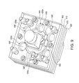
- FIG. 9 shows another partial view of portions of the exemplary system shown in FIG. 4 ;
- FIG. 10 shows another partial view of portions of the exemplary system shown in FIG. 4 ;
- FIG. 11 shows another partial view of portions of the exemplary system shown in FIG. 4 ;
- FIG. 12 shows a partial view of an alternative system according to aspects of the invention.
- FIG. 13 shows another partial view of portions of the exemplary system shown in FIG. 12 ;
- FIG. 14 shows another partial view of portions of the exemplary system shown in FIG. 12 ;
- FIG. 15A shows an exemplary implementation of a thermal interface material according to aspects of the invention.
- FIG. 15B shows a plot of the thermal resistivity of the thermal interface material of FIG. 14A ;
- FIG. 16 shows an exemplary implementation of the thermal interface material according to aspects of the invention.
- FIG. 17 shows another exemplary implementation of the thermal interface material according to aspects of the invention.
- FIG. 18 shows another exemplary implementation of the thermal interface material according to aspects of the invention.
- FIG. 19 shows another exemplary implementation of the thermal interface material according to aspects of the invention.
- FIG. 20 shows another exemplary implementation of the thermal interface material according to aspects of the invention.
- the present disclosure relates to an apparatus and method for providing an advanced interface between a thermal controller and an electronic device, such as a solid state electronic device being tested in a controlled environment, referred to as a device under test (DUT).
- a heat sink is operatively connected to a thermal chuck by a zero influence pusher via a free-floating gimbal attachment.
- the zero influence pusher provides the capability to extend and retract the heat sink into and out of contact with a DUT, without applying an uneven force (e.g., torque, moment, etc.) to the DUT.
- at least the heat sink is removably attached to the thermal chuck.
- a thermal interface material comprising nano tubes is provided.
- heat sink means any heat transfer element or device (e.g., resistive heater, radiator, heat pipe, cross-flow heat exchanger, etc.) structured and arranged to transfer heat to and/or from an object which it is in thermal contact with.
- FIG. 4 shows a thermal controller and an associated zero influence pusher comprising a free-floating gimbal attachment for a heat sink, according to a first embodiment of the invention.
- the zero influence pusher may be used with any suitable thermal controller that is structured and arranged to facilitate bringing a heat sink into contact with a DUT.
- the zero influence pusher is used with the thermal chuck described in Applicants' co-pending application PCT/US07/74727, the disclosure of which is hereby expressly incorporated by reference in its entirety.
- a zero influence pusher 502 operatively connected between a thermal chuck 500 and a heat sink 515 .
- the zero influence pusher 502 allows the heat sink 515 to be brought into contact with a DUT (not shown) at a test site on substrate 508 .
- a mixing chamber 517 is structured and arranged in selective fluid communication with various fluid ports 505 a , 505 b , 505 s , 505 a R, 505 b R, 505 s R, for maintaining the heat sink 515 , and therefore the DUT, at a desired temperature.
- Valve 524 controls the fluid communication between heat sink 515 and fluid ports 505 a , 505 b , 505 s , 505 a R, 505 b R, 505 s R, as described in greater detail below.
- a “fluid” may be any non-solid material, including but not limited to a liquid, a gas, particulates, granules or any combination thereof.
- FIG. 5 shows a schematic view of the exemplary thermal chuck 500 in accordance with a non-limiting embodiment of the invention, which utilizes three fluid sources (also referred to as reservoirs), namely a cold fluid source 510 , a setpoint fluid source 513 and a hot fluid source 520 .
- the fluid in the setpoint fluid source 513 is set at a temperature higher than the fluid in the cold fluid source 510 . More specifically, the fluid in the setpoint fluid source 513 is set at a temperature that is generally the same as a setpoint temperature of a DUT (taking into consideration the thermal loss potentially occurring though the thermal chuck 500 ). For example, if the setpoint of the DUT is 80 degrees Celsius, the temperature of the fluid in the setpoint fluid source 513 may be set at, e.g., 85 degrees Celsius.
- the temperature of the fluid in the hot fluid source is set at a temperature higher than the fluid in the setpoint fluid source 513 .
- the set point fluid temperature may be closer to the cold fluid temperature than it is to the hot fluid temperature. While FIG. 5 shows three fluid sources of three different temperatures 510 , 513 , 520 , it is appreciated by those of skill in the art that more than three fluid sources of more than three different temperatures, or that one or more fluids having a single temperature, may be used in alternative embodiments.
- the system may include a cold fluid source, a first setpoint fluid source, a second setpoint fluid source, a third setpoint fluid source and a hot fluid source, totaling five different fluid sources containing respective fluids of five different temperatures.
- a conduit 505 interconnects the three fluid sources 510 , 513 , 520 to heat sink 515 .
- cold fluid passes though cold fluid conduit 505 a and is directed through the thermal chuck 500 via manifold 580 , where the cold fluid communicates with a valve 524 (including but not limited to a disk valve).
- setpoint fluid exits the setpoint source 513 to enter the hot fluid source 520 via conduit 505 b .
- the hot fluid passes through conduit 505 b and is directed through the thermal chuck 500 via manifold 580 , where the hot fluid communicates with valve 524 .
- Setpoint fluid not directed to the hot fluid source 520 passes through conduit 505 s is directed through the thermal chuck 500 via manifold 580 , where the setpoint fluid communicates with valve 524 .
- setpoint fluid may exclusively mix with cold fluid, for increased energy efficiency. In other words, eliminating the direct mixing of cold and hot fluid results in increased energy efficiency, since directly mixing cold and hot fluid results in significant energy consumption as well as increased chance of thermal gradients across the heat sink 515 .
- FIG. 6 schematically shows a disk valve 524 in communication with cold fluid conduit 505 a , setpoint fluid conduit 505 s and hot fluid conduit 505 b .
- the valve 524 is preferably mounted immediately above the heat sink, and rotates either 180 or 360 degrees to discharge a desired mixture of cold fluid, setpoint fluid and hot fluid, such that combined fluid of a predetermined temperature may flow to the heat sink 515 (shown in FIG. 5 ).
- valve 524 when the valve 524 is at zero degrees of rotation, cold fluid is discharged; when the valve is at 90 degrees of rotation, setpoint fluid is discharged; when the valve is at 180 degrees of rotation, hot fluid is discharged; and when the valve is at 270 degrees of rotation, fluid that has already flowed to the heat sink 515 is returned via return conduit 505 R (shown in FIG. 5 ), thereby enabling fluid to be discharged at a generally constant rate.
- the valve 524 is preferably located at the junction of the fluid supply conduits 505 a , 505 s and 505 b . For optimal fast temperature response, it is preferable for the mixing of fluids to be at the inlet of the heat sink, to minimize fluid transit time.
- the heat sink 515 and mixing chamber 517 (shown in FIG. 4 ) only require a single inlet and a single outlet. Further, problems with incompressibility of the fluid are reduced due to the close proximity of the fluid mixing to the heat sink 515 . Additionally, the above-described configuration reduces problems with repeatability and hysteresis.
- the invention is not limited to the above-described disk valve, and other suitable valves and/or regulators may be used with the invention.
- FIG. 7 is a graph showing the mixing of cold, setpoint and hot fluids in relation to the actuation of the valve 524 .
- FIG. 7 shows the combined flow of to be at a constant rate of approximately two liters per minute; however, those of skill in the art would appreciate that this rate can be greater than or less than two liters per minute and can be varied instead of constant.
- FIGS. 4-7 are described with respect to a three fluid system, it is understood that the invention is not limited to use with a three fluid system.
- a single fluid may be used in which portions of the fluid having different respective temperatures are mixed in varying proportions within a heat sink to maintain and control the temperature of the DUT.
- At least two different fluids may be mixed in varying proportions within the heat sink to maintain and control the temperature of the DUT.
- two or more different fluids in different states of matter may be used in the present invention.
- a gaseous fluid may be mixed with a liquid fluid, in accordance with a non-limiting feature of the present invention.
- the invention may be used with more than three fluids.
- FIG. 5 shows that fluid from return conduit 505 R is returned to the setpoint fluid source 513 via setpoint fluid return conduit 505 s R and is also returned to the cold fluid source 510 via cold fluid return conduit 505 a R.
- three fluid supply conduits 505 a , 505 s , 505 b are supplied to the thermal chuck, only two fluid return conduits 505 a R, 505 s R (or 505 a R, 505 b R; or 505 s R, 505 b R) may be supplied from the thermal chuck.
- FIG. 5 shows that fluid from return conduit 505 R is returned to the setpoint fluid source 513 via setpoint fluid return conduit 505 s R and is also returned to the cold fluid source 510 via cold fluid return conduit 505 a R.
- FIG. 4 shows a schematic perspective view of the thermal chuck 500 having three fluid supply conduits 505 a , 505 s , 505 b supplied to the thermal chuck, and three fluid return conduits 505 a R, 505 s R, 505 b R supplied from the thermal chuck.
- Those of skill in the art would appreciate that in alternative embodiments, only one fluid return conduit may be supplied from the thermal chuck.
- the setpoint fluid return conduit 505 s R is located next to the hot fluid return conduit 505 b R on the upper portion of the thermal chuck 500 , thereby resulting in little thermal loss.
- the aforementioned combined fluid return could be performed either internally or externally to the chuck 500 .
- any method of transferring thermal energy from a fluid i.e., for maintaining a cold delta T and a hot delta T
- the fluids may have any number of different temperatures, or alternatively, the fluid may be a single temperature.
- the fluid flowing through the conduit 305 may be divided into three or more portions, each having a different delta T, which may be mixed in various proportions to achieve a desired mixed fluid portion temperature.
- FIG. 8 shows a partial view of a system according to aspects of the invention.
- the system includes, inter alia, a thermal chuck 500 , cold fluid return conduit 505 a R, set fluid supply conduit 505 s , hot fluid supply conduit 505 b , valve 524 , heat sink 515 , mixing chamber 517 , and substrate 508 (which may be similar to those elements described above with respect to FIGS. 4-7 ).
- Thermal chuck 500 includes an upper plate 605 , pneumatic manifold 610 , fluid manifold 615 , and lower plate 620 , each of which may be composed of any suitable material, such as, for example, metal, plastic, composite, etc.
- the upper plate 605 provides connection locations (e.g., threaded ports) for the fluid supply conduits 505 a , 505 s , 505 b , fluid return conduits 505 a R, 505 s R, 505 b R, and a pressure port 550 (described in greater detail below).
- the pneumatic manifold 610 , fluid manifold 615 , and lower plate 620 comprise axially aligned bores that combine to form six respective chambers 630 that are structured and arranged to operatively connect the thermal chuck 500 to the zero influence pusher 502 .
- chambers 630 are shown substantially symmetrically disposed about coincident central axes of the thermal chuck 500 and zero influence pusher 502 ; however, any suitable number of chambers 630 (e.g., greater than or less than the six shown) may be used with the invention.
- each chamber 630 Disposed within each chamber 630 , between the pneumatic manifold 610 and the fluid manifold 615 , is an upper diaphragm 635 . Also disposed within each chamber 630 , between the fluid manifold 610 and the lower plate 620 , is a lower diaphragm 640 .
- the upper diaphragm 635 and lower diaphragm 640 divide each chamber 630 into an upper chamber portion 630 a , a middle chamber portion 630 b , and a lower chamber portion 630 c .
- the upper diaphragm 635 provides a generally air-tight seal between the upper chamber portion 630 a and the middle chamber portion 630 b
- the lower diaphragm 640 includes a hole that allows fluid communication between the middle chamber portion 630 b and the lower chamber portion 630 c.
- the upper diaphragm 635 and lower diaphragm 640 each comprise respective rolling diaphragms, such as that manufactured by Bellofram Corp., of Newell, W. Va.; although those of ordinary skill in the art will recognize that any suitable rolling diaphragm may be used with the invention.
- a unitary upper diaphragm member 636 that integrally includes each respective upper diaphragm 635 may be sandwiched between the pneumatic manifold 610 and the fluid manifold 615 , as shown in FIGS. 8 and 11 .
- a unitary lower diaphragm member 641 that integrally includes each respective lower diaphragm 640 may be sandwiched between the fluid manifold 615 and the lower plate 620 .
- an upper chamber element 650 a is disposed within each upper chamber portion 630 a ; a middle chamber element 650 b is disposed within each middle chamber portion 630 b ; and a lower chamber element 650 c is disposed within each lower chamber portion 650 c .
- the respective lower chamber elements 650 c are connected to the zero influence pusher body 655 .
- the upper diaphragm 635 and the lower diaphragm 640 are disposed in opposite orientations, which allows for axial displacement of the upper chamber element 650 a , middle chamber element 650 b , and lower chamber element 650 c , in unison, along a central axis of the chamber 630 .
- the diaphragms 635 , 640 and the chamber elements 650 a , 650 b , 650 c , in each respective chamber 630 combine to form a floating attachment of the zero influence pusher 502 to the thermal chuck 500 .
- a central axis of the zero influence pusher 502 is substantially coincident with a central axis of the thermal chuck 500 , and the respective floating attachments are arranged substantially symmetrically about these axes.
- the floating attachments collectively form a free-floating gimbal connection between the thermal chuck 500 and the zero influence pusher 502 .
- This free-floating gimbal connection provides the zero influence pusher 502 with six degree-of-freedom movement relative to the thermal chuck 500 , as described in greater detail below.
- FIG. 9 shows the system of FIG. 8 with the upper plate 605 transparent so that the pneumatic manifold 610 is visible.
- each upper chamber portion 630 a is in communication with pressure port 550 via pneumatic ports 645 formed in the pneumatic manifold 610 .
- the axial position of the zero influence pusher 502 may be controlled by adjusting the pneumatic pressure in the upper chamber portions 630 a .
- the floating fluid attachments are biased toward a neutral position along the z-axis due to the opposed orientation of the upper diaphragm 635 and the lower diaphragm 640 .
- the zero influence pusher 502 may be moved axially downward (i.e., out of the thermal chuck 500 along the z-axis).
- a negative pressure e.g., a vacuum
- the zero influence pusher 502 may be moved axially upward (i.e., into the thermal chuck 500 along the z-axis).
- the zero influence pusher 502 may travel 1 mm in each direction from the neutral position, for a total of 2 mm of travel in the z-axis direction.
- the invention is not limited to this amount of travel, and the respective components may be designed (e.g., sized) to provide any suitable amount of travel in the z-axis direction.
- the travel of the zero influence pusher 502 in the z-axis direction allows the heat sink 515 to be controllably axially moved until it comes into contact the substrate 508 that holds the DUT.
- axially refers to a direction generally parallel to the coincident axis of the zero influence pusher 502 and the thermal chuck 500 . Owing to the free-floating connection between the thermal chuck 500 and the zero influence pusher 502 provided by the diaphragms 635 , 640 , a point of contact between the heat sink and the DUT becomes a center of rotation for the gimbal connection between the thermal chuck 500 and the zero influence pusher 502 .
- the interface surface of the heat sink 515 may be pivoted or rotated, if necessary, to come into a substantially co-planar relationship with the interface surface of the DUT.
- the center of rotation of the free-floating gimbal connection (and, therefore, of the heat sink 515 ) is a contact point between the heat sink 515 and the DUT, any rotation of the heat sink 515 is accomplished without accompanying translation of the heat sink 515 relative to the DUT (e.g., when the heat sink is moving and the DUT is stationary). Accordingly, the heat sink 515 and DUT are brought into a substantially co-planar interface without any undesirable scrubbing (e.g., abrading) of the surface of the DUT by the heat sink 515 .
- any undesirable scrubbing e.g., abrading
- any force applied to the DUT by the heat sink 515 is substantially perpendicular to the surface of the DUT. That is to say, implementations of the invention avoid applying unwanted torque to the DUT.
- the upper diaphragm 635 and lower diaphragm 640 both comprise rolling diaphragms that are substantially free of static friction, axial force is applied evenly to the zero influence pusher 502 , and therefore to the DUT. In this manner, jerk (i.e., a sudden change in acceleration when initially overcoming static friction) is substantially eliminated, and the possibility of jerk-induced damage to the heat sink 515 and/or DUT is minimized.
- FIG. 10 shows the exemplary system of FIG. 8 with the top plate 605 , pneumatic manifold 610 , and unitary upper diaphragm member 636 removed.
- each middle chamber portion 630 b is in fluid communication with a respective fluid conduit (e.g., 505 a , 505 s , 505 b , 505 a R, 505 s R, 505 b R) via cross ports 670 formed in the fluid manifold 615 .
- the upper chamber element 650 a and middle chamber element 650 b are not shown, such that the lower diaphragms 640 are visible in the chambers 630 .
- each middle chamber element 650 b includes a cross bore 675 that intersects with an axial bore 680 .
- the cross bore 675 is in fluid communication with the middle chamber portion 630 b
- the axial bore 680 is in fluid communication with a through bore 685 of the lower chamber element 650 c via a hole in the lower diaphragm 640 .
- each through bore 685 is in fluid communication with a respective fluid channel 690 of the zero influence pusher body 655 , whereby each fluid channel 690 leads to the valve 524 .
- controlled movement of the valve 524 selectively provides fluid communication between the fluid supply conduits 505 a , 505 s , 505 b and an inlet duct 693 of the mixing chamber 517 , and between an outlet duct 695 of the mixing chamber 517 and the fluid return conduits 505 a R, 505 s R, 505 b R.
- the heat sink 515 and therefore the DUT, can be maintained at a desired temperature (as described above with respect to FIGS. 4-7 ).
- the system as described may be used for set point temperatures (e.g., DUT test temperatures) ranging from approximately ⁇ 80° C. to approximately 200° C.
- the invention is not limited to use in this temperature range, and that the system may be designed for use at any suitable temperature.
- pressure fluctuations may occur in the respective fluid conduits (e.g., 505 a , 505 s , 505 b , 505 a R, 505 s R, 505 b R) during operation of the system.
- a supply conduit may momentarily have a higher fluid pressure than a return conduit, and vice versa.
- each diaphragm 635 , 640 of a chamber 630 sees the same (i.e., offsetting) pressure, such that there is no axial force induced to the zero influence pusher 502 by the fluid supply, thereby helping minimize unwanted uneven force (e.g., torque) on the heat sink and/or DUT.
- FIG. 11 shows the exemplary system of FIG. 8 with the top plate 605 removed, such that the unitary upper diaphragm member 636 is visible. While the invention has been described with respect to a unitary upper diaphragm member 636 that collectively embodies the plural diaphragms 635 , it is noted that the invention is not limited to this exemplary embodiment. For example, separate diaphragms 635 , which are not connected by a unitary upper diaphragm member 636 , may be disposed in each respective chamber 630 .
- the mixing chamber 517 (including inlet duct 693 and outlet duct 695 ) and the heat sink 515 are selectively removable as a unit from the zero influence pusher body 655 .
- the mixing chamber 517 may be attached to the zero influence pusher body 655 by a selectively disengageable connection, including but not limited to a friction fit, snap fit, quick-disconnect, or any other suitable connection.
- a selectively disengageable connection including but not limited to a friction fit, snap fit, quick-disconnect, or any other suitable connection.
- FIGS. 12-14 show partial views of an alternative system according to further aspects of the invention.
- the thermal chuck 710 shown in FIG. 12 includes four fluid conduits 715 , instead of the six shown in FIG. 8 .
- the four fluid conduits 715 may comprise, for example, a hot supply conduit, a hot return conduit, a cold supply conduit, and a cold return conduit.
- the four fluid conduits may comprise, for example, a hot supply conduit, a setpoint supply conduit, a cold supply conduit, and a single return conduit.
- the thermal chuck 710 further comprises a pneumatic manifold 720 , fluid manifold 725 , and bottom plate 730 . Connected to the bottom plate 730 is another embodiment of a zero influence pusher 785 comprising at least a mixing chamber 735 and a heat sink 740 .
- the pneumatic manifold 720 , fluid manifold 725 , and bottom plate 730 comprise axially aligned bores that cooperate to form four respective chambers 745 symmetrically spaced about the coincident central axis of the thermal chuck 710 and zero influence pusher 785 .
- Disposed in each chamber 745 is an upper rolling diaphragm 750 and a lower rolling diaphragm 755 , which divide the chamber 745 into an upper chamber portion 745 a , a middle chamber portion 745 b , and a lower chamber portion 745 c .
- An upper chamber element 760 a is disposed in the upper chamber portion 745 a .
- a middle chamber element 760 b is disposed in the middle chamber portion 745 b .
- a lower chamber element 760 c is disposed in the lower chamber portion 745 c.
- the fluid manifold 725 contains respective ports 765 that connect the respective fluid conduits 715 to respective middle chamber portions 745 b .
- Each middle chamber element 760 b has a cross bore 770 that intersects with an axial bore 775 .
- the cross bore 770 is in fluid communication with the middle chamber portion 745 b .
- the axial bore 775 in turn, communicates with a through bore 780 of the lower chamber element 760 c .
- the through bore 780 of each lower chamber element 760 c is provided in fluid communication with the mixing chamber 735 . In this manner, a fluid pathway is provided between each fluid conduit 715 and the heat sink 740 .
- the diaphragms 750 , 755 provide a floating connection of the zero influence pusher 785 to the thermal chuck 710 .
- the zero influence pusher 785 maintains six degree of freedom movement relative to the thermal chuck 710 .
- the pneumatic manifold 720 comprises pneumatic ports 790 that provide a pathway between pressure conduit 795 and the upper chamber portions 745 a .
- the zero influence pusher 785 may be moved axially (i.e., in the z-axis direction) by appropriate application of pressure (or vacuum) to the pressure conduit 795 .
- the mixing chamber 735 and the heat sink 740 are selectively removable as a unit from the thermal chuck 710 .
- the mixing chamber 735 may be attached to the four respective lower chamber elements 760 c by selectively disengageable connections 797 , including but not limited to friction fit, snap fit, quick-disconnect, or any other suitable connections.
- different heat sinks having, for example, different thermal interface areas and/or different thermal interface materials
- the zero influence pusher is not limited to use with any one specific thermal chuck. Rather, implementations of the invention may be used with any desired thermal control system in which it is desired to isolate the heat sink/DUT interface from external forces generated by the remainder of the system. In this way, the zero influence pusher substantially minimizes unwanted influence of the thermal controller structure to the interface between the heat sink and the DUT. Also, the zero influence pusher provides a six degree of freedom gimbaling of the heat sink to the DUT at the interface, thereby eliminating unbalanced force (e.g., torque) at the interface while also eliminating scrubbing (e.g., abrading) of the heat sink against the DUT. Furthermore, the pneumatically controlled axial movement of the zero influence pusher allows substantially jerk-free movement of the heat sink, and the uniform application of a force against the DUT.
- unbalanced force e.g., torque
- scrubbing e.g., abrading
- FIG. 15A shows an exemplary embodiment of a thermal interface material comprising a plurality of nano tubes 805 according to aspects of the invention.
- the nano tubes 805 comprise carbon nano tubes grown on a substrate 810 , although the invention is not limited to this type of nano tube. Because the nano tubes 805 are flexible, yet retain their thermal length when bent, the nano tubes 805 are capable of conforming to deviations in the surface of the DUT 815 (as shown in FIG. 15A ) while providing a substantially uniform thermal resistivity across the surface of the DUT 815 (as shown in FIG. 15B ). Accordingly, the nano tubes 805 minimize unwanted thermal gradients across the DUT 815 .
- the nano tubes 805 comprise approximately 150 ⁇ m height carbon nano tubes that are grown on a substrate 810 .
- the substrate 810 may comprise, for example, a surface of a heat sink (e.g., heat sink 515 described above), such as a copper surface. Growing the carbon nano tubes directly on a surface of a heat sink provides a beneficial low thermal resistance.
- the substrate 810 on which the nano tubes 805 are grown may be attached to a heat sink via re-workable thermal solder or thermal grease.
- the nano tubes 805 have a thermal resistivity of less than or equal to approximately 0.07 C/(W/cm 2 ) (where C is degrees Celsius, W is watts, and cm is centimeters) at operating pressures ranging from about 15 psi to about 75 psi (where psi is pounds per square inch), substantially no thermal mass, and can accommodate greater than 50 ⁇ m flatness.
- the invention is not limited to nano tubes having these specific properties, and other types of nano tubes may be used with the invention.
- nano tubes having a height in the range of about 25 ⁇ m to about 50 ⁇ m are contemplated for use with the invention.
- embodiments of the invention may utilize nano tubes that are either encapsulated or non-encapsulated.
- FIGS. 16 and 17 show further aspects of how the nano tubes 805 act as a flexible thermal interface material between the substrate 810 and DUT 815 .
- a particle 820 e.g., debris
- the nano tubes 805 which act as elongate thermal springs, may flex around the particle 820 .
- a thermal interface material composed of a plurality of nano tubes 805 overlaps a relatively smaller DUT 815 without causing stress concentrations at the edges of the DUT 815 . This minimizes possible damage to the DUT 815 , while also avoiding thermal gradients due to stress concentrations.
- FIG. 18 shows an embodiment in which hard stops 840 are provided on the substrate 810 amongst the nano tubes 805 .
- Such hard stops 840 are employed, for example, when it is desired to transmit a force from the substrate 810 to the DUT 815 , as is required under some testing conditions.
- the hard stops 840 are composed of any suitable material, and may be designed to any suitable size or dimension (e.g., length, width, and height), according to the intended use of the system. However, in a preferred embodiment, the hard stops 840 are shorter than the length of the uncompressed nano tubes 805 , such that the nano tubes 805 must compress to some degree before the hard stops 840 engage the surface of the DUT 815 .
- Such an arrangement ensures a uniform thermal interface between the substrate 810 and the DUT 815 , while allowing a force (e.g., approximately 100 pounds) to be applied to the DUT 815 .
- FIG. 19 shows an embodiment in which hard stops 840 and vacuum channels 845 are provided at the substrate 810 .
- the hard stops 840 function as discussed above with respect to FIG. 18 .
- the vacuum channels 845 allow a negative pressure to be applied to the volume enclosed by the substrate 810 , DUT 815 , and hard stops 840 .
- This provides a vacuum cup that allows the DUT 810 to be transported (e.g., moved) while still maintaining desired thermal properties and/or force application of the interface between the substrate 810 and DUT 815 .
- FIG. 20 shows another embodiment of the thermal interface material according to aspects of the invention.
- the carbon nano tubes 805 a , 805 b are attached to a substrate 850 on an upper side 850 a and a lower side 850 b .
- the substrate 850 and carbon nano tubes 805 may be easily placed between a DUT 815 and a heat sink 855 without the use of thermal grease or other thermal interface materials.
- the substrate may comprise foil, such as, for example, copper foil on which the carbon nano tubes 805 a , 805 b are grown.
- the substrate 850 may have a thickness that allows the substrate 850 to be flexible. Such flexibility of the substrate 850 helps optimize conformance of the also flexible carbon nano tubes 805 a , 805 b to the surfaces of the DUT 815 and the heat sink 855 .
- implementations of the invention comprising a thermal interface material of nano tubes provide a substantially uniform thermal interface that does not damage the DUT surface and can overlap the DUT edges without causing stress concentrations.
- the thermal interface material comprising nano tubes according to aspects of the invention will not bum off or freeze like a thermal interface liquid, and can accommodate debris without damaging the DUT.
Abstract
Description
Claims (6)
Applications Claiming Priority (1)
| Application Number | Priority Date | Filing Date | Title |
|---|---|---|---|
| PCT/US2007/078512 WO2009035459A1 (en) | 2007-09-14 | 2007-09-14 | Advanced thermal control interface |
Publications (2)
| Publication Number | Publication Date |
|---|---|
| US20100163217A1 US20100163217A1 (en) | 2010-07-01 |
| US8757250B2 true US8757250B2 (en) | 2014-06-24 |
Family
ID=40452288
Family Applications (1)
| Application Number | Title | Priority Date | Filing Date |
|---|---|---|---|
| US12/278,843 Active 2030-08-15 US8757250B2 (en) | 2007-09-14 | 2007-09-14 | Advanced thermal control interface |
Country Status (7)
| Country | Link |
|---|---|
| US (1) | US8757250B2 (en) |
| JP (1) | JP5451618B2 (en) |
| KR (1) | KR100996197B1 (en) |
| CN (1) | CN101505861B (en) |
| DE (1) | DE112007003648T5 (en) |
| TW (1) | TWI390375B (en) |
| WO (1) | WO2009035459A1 (en) |
Cited By (2)
| Publication number | Priority date | Publication date | Assignee | Title |
|---|---|---|---|---|
| US20110226442A1 (en) * | 2010-03-17 | 2011-09-22 | Delta Design, Inc. | Alignment mechanism |
| US20140253155A1 (en) * | 2013-03-07 | 2014-09-11 | Advantest Corporation | Adaptive thermal control |
Families Citing this family (9)
| Publication number | Priority date | Publication date | Assignee | Title |
|---|---|---|---|---|
| JP4792546B2 (en) | 2008-10-29 | 2011-10-12 | 株式会社アドバンテスト | Temperature control device for electronic parts |
| WO2012166122A1 (en) * | 2011-05-31 | 2012-12-06 | Aavid Thermalloy, Llc | Heat sink mount with positionable heat sinks |
| US9269603B2 (en) | 2013-05-09 | 2016-02-23 | Globalfoundries Inc. | Temporary liquid thermal interface material for surface tension adhesion and thermal control |
| KR20150108578A (en) * | 2014-03-18 | 2015-09-30 | 가부시키가이샤 어드밴티스트 | Temperature control apparatus and test system |
| US10234409B2 (en) * | 2015-09-17 | 2019-03-19 | Dunan Microstaq, Inc. | Test equipment arrangement having a superheat controller |
| US10022896B2 (en) * | 2015-11-23 | 2018-07-17 | The Boeing Company | Controlling the heating of a composite part |
| TWI755492B (en) * | 2017-03-06 | 2022-02-21 | 美商卡爾拜斯有限公司 | Carbon nanotube-based thermal interface materials and methods of making and using thereof |
| US10753971B2 (en) | 2018-04-03 | 2020-08-25 | Advantest Corporation | Heat exchanger and electronic device handling apparatus including the same |
| WO2020014163A1 (en) * | 2018-07-09 | 2020-01-16 | Delta Design, Inc. | Assembly and sub-assembly for thermal control of electronic devices |
Citations (41)
| Publication number | Priority date | Publication date | Assignee | Title |
|---|---|---|---|---|
| US3463224A (en) * | 1966-10-24 | 1969-08-26 | Trw Inc | Thermal heat switch |
| US3556205A (en) * | 1968-12-02 | 1971-01-19 | Aro Corp | Underwater heat generator |
| US3563307A (en) * | 1970-02-02 | 1971-02-16 | Nasa | Radiator deployment actuator |
| US4676300A (en) * | 1984-11-15 | 1987-06-30 | Kabushiki Kaisha Toshiba | Heat radiation control device |
| US4759403A (en) * | 1986-04-30 | 1988-07-26 | International Business Machines Corp. | Hydraulic manifold for water cooling of multi-chip electric modules |
| US4910642A (en) * | 1988-12-05 | 1990-03-20 | Sundstrand Corporation | Coolant activated contact compact high intensity cooler |
| US4951740A (en) * | 1988-06-27 | 1990-08-28 | Texas A & M University System | Bellows heat pipe for thermal control of electronic components |
| US5050037A (en) * | 1984-01-26 | 1991-09-17 | Fujitsu Limited | Liquid-cooling module system for electronic circuit components |
| US5088980A (en) | 1990-05-31 | 1992-02-18 | The United States Of America As Represented By The Department Of Health And Human Services | Intra-urethral valve with integral spring |
| US5124557A (en) | 1989-10-03 | 1992-06-23 | Superion Limited | Apparatus and methods relating to ion implantation and heat transfer |
| US5365400A (en) * | 1988-09-09 | 1994-11-15 | Hitachi, Ltd. | Heat sinks and semiconductor cooling device using the heat sinks |
| US5394299A (en) * | 1992-12-21 | 1995-02-28 | International Business Machines Corporation | Topology matched conduction cooling module |
| US5420753A (en) * | 1992-11-09 | 1995-05-30 | Nec Corporation | Structure for cooling an integrated circuit |
| US5704416A (en) * | 1993-09-10 | 1998-01-06 | Aavid Laboratories, Inc. | Two phase component cooler |
| US5977785A (en) * | 1996-05-28 | 1999-11-02 | Burward-Hoy; Trevor | Method and apparatus for rapidly varying the operating temperature of a semiconductor device in a testing environment |
| US6173760B1 (en) * | 1998-08-04 | 2001-01-16 | International Business Machines Corporation | Co-axial bellows liquid heatsink for high power module test |
| US6268995B1 (en) * | 2000-06-08 | 2001-07-31 | Jennings Technology | Double-bellows vacuum variable capacitor |
| US20010054893A1 (en) | 2000-06-23 | 2001-12-27 | Tsuyoshi Yamashita | Contact arm and electronic device testing apparatus using the same |
| US20020134542A1 (en) * | 2001-03-20 | 2002-09-26 | Unsworth John Duncan | Heat exchanger with passive in-line temperature control |
| US6616999B1 (en) * | 2000-05-17 | 2003-09-09 | Raymond G. Freuler | Preapplicable phase change thermal interface pad |
| US20040052052A1 (en) * | 2002-09-18 | 2004-03-18 | Rivera Rudy A. | Circuit cooling apparatus |
| US20040139756A1 (en) | 2001-05-31 | 2004-07-22 | Wall Charles B. | Apparatus and method for controlling the temperature of an electronic device under test |
| US20040194944A1 (en) | 2002-09-17 | 2004-10-07 | Hendricks Terry Joseph | Carbon nanotube heat-exchange systems |
| US6817969B2 (en) | 2003-01-31 | 2004-11-16 | Tetra Laval Holdings & Finance, Sa | Carton puller vacuum head and method |
| US20050103040A1 (en) * | 2003-11-14 | 2005-05-19 | Krempel Benjamin J. | Systems for regulating the temperature of a heating or cooling device using non-electric controllers and non-electric controllers therefor |
| US20050252637A1 (en) * | 2004-05-14 | 2005-11-17 | Hon Hai Precision Industry Co., Ltd. | Heat sink and method for making same |
| US6972056B1 (en) | 2002-04-25 | 2005-12-06 | The United States Of America As Represented By The Administration Of The National Aeronautics And Space Administration | Carbon nanotube purification |
| US20060043649A1 (en) | 2002-01-11 | 2006-03-02 | Trustees Of Boston College | Reinforced carbon nanotubes |
| US7055586B2 (en) | 2001-05-25 | 2006-06-06 | Maruyasu Industries Co., Ltd. | Multitubular heat exchanger |
| US20060141308A1 (en) * | 2004-12-23 | 2006-06-29 | Becerra Juan J | Apparatus and method for variable conductance temperature control |
| US7100389B1 (en) * | 2002-07-16 | 2006-09-05 | Delta Design, Inc. | Apparatus and method having mechanical isolation arrangement for controlling the temperature of an electronic device under test |
| US7258160B2 (en) | 2002-09-25 | 2007-08-21 | Sony Corporation | Heat transfer element, cooling device and electronic device having the element |
| US20080042667A1 (en) | 2004-07-23 | 2008-02-21 | Advantest Corporation | Electronic Device Test Apparatus and Method of Configuring Electronic Device Test Apparatus |
| US7411792B2 (en) * | 2002-11-18 | 2008-08-12 | Washington State University Research Foundation | Thermal switch, methods of use and manufacturing methods for same |
| US20080223555A1 (en) * | 2007-03-16 | 2008-09-18 | Centipede Systems, Inc. | Method and apparatus for controlling temperature |
| US7605581B2 (en) * | 2005-06-16 | 2009-10-20 | Delta Design, Inc. | Apparatus and method for controlling die force in a semiconductor device testing assembly |
| US7732918B2 (en) * | 2003-08-25 | 2010-06-08 | Nanoconduction, Inc. | Vapor chamber heat sink having a carbon nanotube fluid interface |
| US7743763B2 (en) * | 2007-07-27 | 2010-06-29 | The Boeing Company | Structurally isolated thermal interface |
| US20100224352A1 (en) * | 2007-07-30 | 2010-09-09 | Advantest Corporation | Thermal controller for electronic devices |
| US7870800B2 (en) * | 2006-05-15 | 2011-01-18 | Centipede Systems, Inc. | Apparatus including a fluid coupler interfaced to a test head |
| US20110198059A1 (en) * | 2008-08-01 | 2011-08-18 | Commissariat A L'energie Atomique Et Aux Ene Alt | Heat exchange structure and cooling device comprising such a structure |
Family Cites Families (1)
| Publication number | Priority date | Publication date | Assignee | Title |
|---|---|---|---|---|
| CN2783540Y (en) * | 2005-04-15 | 2006-05-24 | 吉林省巨力电池有限公司 | Vacuum thermo-pressing shaping machine |
-
2007
- 2007-09-14 KR KR1020087020873A patent/KR100996197B1/en active IP Right Grant
- 2007-09-14 WO PCT/US2007/078512 patent/WO2009035459A1/en active Application Filing
- 2007-09-14 DE DE112007003648T patent/DE112007003648T5/en not_active Withdrawn
- 2007-09-14 JP JP2010524827A patent/JP5451618B2/en not_active Expired - Fee Related
- 2007-09-14 US US12/278,843 patent/US8757250B2/en active Active
- 2007-09-14 CN CN2007800286558A patent/CN101505861B/en active Active
-
2008
- 2008-08-19 TW TW097131556A patent/TWI390375B/en active
Patent Citations (43)
| Publication number | Priority date | Publication date | Assignee | Title |
|---|---|---|---|---|
| US3463224A (en) * | 1966-10-24 | 1969-08-26 | Trw Inc | Thermal heat switch |
| US3556205A (en) * | 1968-12-02 | 1971-01-19 | Aro Corp | Underwater heat generator |
| US3563307A (en) * | 1970-02-02 | 1971-02-16 | Nasa | Radiator deployment actuator |
| US5050037A (en) * | 1984-01-26 | 1991-09-17 | Fujitsu Limited | Liquid-cooling module system for electronic circuit components |
| US4676300A (en) * | 1984-11-15 | 1987-06-30 | Kabushiki Kaisha Toshiba | Heat radiation control device |
| US4759403A (en) * | 1986-04-30 | 1988-07-26 | International Business Machines Corp. | Hydraulic manifold for water cooling of multi-chip electric modules |
| US4951740A (en) * | 1988-06-27 | 1990-08-28 | Texas A & M University System | Bellows heat pipe for thermal control of electronic components |
| US5365400A (en) * | 1988-09-09 | 1994-11-15 | Hitachi, Ltd. | Heat sinks and semiconductor cooling device using the heat sinks |
| US4910642A (en) * | 1988-12-05 | 1990-03-20 | Sundstrand Corporation | Coolant activated contact compact high intensity cooler |
| US5124557A (en) | 1989-10-03 | 1992-06-23 | Superion Limited | Apparatus and methods relating to ion implantation and heat transfer |
| US5088980A (en) | 1990-05-31 | 1992-02-18 | The United States Of America As Represented By The Department Of Health And Human Services | Intra-urethral valve with integral spring |
| US5420753A (en) * | 1992-11-09 | 1995-05-30 | Nec Corporation | Structure for cooling an integrated circuit |
| US5394299A (en) * | 1992-12-21 | 1995-02-28 | International Business Machines Corporation | Topology matched conduction cooling module |
| US5704416A (en) * | 1993-09-10 | 1998-01-06 | Aavid Laboratories, Inc. | Two phase component cooler |
| US5977785A (en) * | 1996-05-28 | 1999-11-02 | Burward-Hoy; Trevor | Method and apparatus for rapidly varying the operating temperature of a semiconductor device in a testing environment |
| US6173760B1 (en) * | 1998-08-04 | 2001-01-16 | International Business Machines Corporation | Co-axial bellows liquid heatsink for high power module test |
| US6616999B1 (en) * | 2000-05-17 | 2003-09-09 | Raymond G. Freuler | Preapplicable phase change thermal interface pad |
| US6268995B1 (en) * | 2000-06-08 | 2001-07-31 | Jennings Technology | Double-bellows vacuum variable capacitor |
| US20010054893A1 (en) | 2000-06-23 | 2001-12-27 | Tsuyoshi Yamashita | Contact arm and electronic device testing apparatus using the same |
| JP2002005990A (en) | 2000-06-23 | 2002-01-09 | Advantest Corp | Contact arm and electronic component testing device using it |
| US20020134542A1 (en) * | 2001-03-20 | 2002-09-26 | Unsworth John Duncan | Heat exchanger with passive in-line temperature control |
| US7055586B2 (en) | 2001-05-25 | 2006-06-06 | Maruyasu Industries Co., Ltd. | Multitubular heat exchanger |
| US20040139756A1 (en) | 2001-05-31 | 2004-07-22 | Wall Charles B. | Apparatus and method for controlling the temperature of an electronic device under test |
| JP2004527764A (en) | 2001-05-31 | 2004-09-09 | クライオテック インコーポレイテッド | Electronic device temperature control apparatus and temperature control method |
| US20060043649A1 (en) | 2002-01-11 | 2006-03-02 | Trustees Of Boston College | Reinforced carbon nanotubes |
| US6972056B1 (en) | 2002-04-25 | 2005-12-06 | The United States Of America As Represented By The Administration Of The National Aeronautics And Space Administration | Carbon nanotube purification |
| US7100389B1 (en) * | 2002-07-16 | 2006-09-05 | Delta Design, Inc. | Apparatus and method having mechanical isolation arrangement for controlling the temperature of an electronic device under test |
| US20040194944A1 (en) | 2002-09-17 | 2004-10-07 | Hendricks Terry Joseph | Carbon nanotube heat-exchange systems |
| US20040052052A1 (en) * | 2002-09-18 | 2004-03-18 | Rivera Rudy A. | Circuit cooling apparatus |
| US7258160B2 (en) | 2002-09-25 | 2007-08-21 | Sony Corporation | Heat transfer element, cooling device and electronic device having the element |
| US7411792B2 (en) * | 2002-11-18 | 2008-08-12 | Washington State University Research Foundation | Thermal switch, methods of use and manufacturing methods for same |
| US6817969B2 (en) | 2003-01-31 | 2004-11-16 | Tetra Laval Holdings & Finance, Sa | Carton puller vacuum head and method |
| US7732918B2 (en) * | 2003-08-25 | 2010-06-08 | Nanoconduction, Inc. | Vapor chamber heat sink having a carbon nanotube fluid interface |
| US20050103040A1 (en) * | 2003-11-14 | 2005-05-19 | Krempel Benjamin J. | Systems for regulating the temperature of a heating or cooling device using non-electric controllers and non-electric controllers therefor |
| US20050252637A1 (en) * | 2004-05-14 | 2005-11-17 | Hon Hai Precision Industry Co., Ltd. | Heat sink and method for making same |
| US20080042667A1 (en) | 2004-07-23 | 2008-02-21 | Advantest Corporation | Electronic Device Test Apparatus and Method of Configuring Electronic Device Test Apparatus |
| US20060141308A1 (en) * | 2004-12-23 | 2006-06-29 | Becerra Juan J | Apparatus and method for variable conductance temperature control |
| US7605581B2 (en) * | 2005-06-16 | 2009-10-20 | Delta Design, Inc. | Apparatus and method for controlling die force in a semiconductor device testing assembly |
| US7870800B2 (en) * | 2006-05-15 | 2011-01-18 | Centipede Systems, Inc. | Apparatus including a fluid coupler interfaced to a test head |
| US20080223555A1 (en) * | 2007-03-16 | 2008-09-18 | Centipede Systems, Inc. | Method and apparatus for controlling temperature |
| US7743763B2 (en) * | 2007-07-27 | 2010-06-29 | The Boeing Company | Structurally isolated thermal interface |
| US20100224352A1 (en) * | 2007-07-30 | 2010-09-09 | Advantest Corporation | Thermal controller for electronic devices |
| US20110198059A1 (en) * | 2008-08-01 | 2011-08-18 | Commissariat A L'energie Atomique Et Aux Ene Alt | Heat exchange structure and cooling device comprising such a structure |
Non-Patent Citations (1)
| Title |
|---|
| Japan Office action, mail date is Feb. 19, 2013. |
Cited By (5)
| Publication number | Priority date | Publication date | Assignee | Title |
|---|---|---|---|---|
| US20110226442A1 (en) * | 2010-03-17 | 2011-09-22 | Delta Design, Inc. | Alignment mechanism |
| US9500701B2 (en) * | 2010-03-17 | 2016-11-22 | Delta Design, Inc. | Alignment mechanism |
| US11802908B2 (en) | 2010-03-17 | 2023-10-31 | Delta Design, Inc. | Alignment mechanism |
| US20140253155A1 (en) * | 2013-03-07 | 2014-09-11 | Advantest Corporation | Adaptive thermal control |
| US9291667B2 (en) * | 2013-03-07 | 2016-03-22 | Advantest Corporation | Adaptive thermal control |
Also Published As
| Publication number | Publication date |
|---|---|
| DE112007003648T5 (en) | 2010-08-26 |
| TWI390375B (en) | 2013-03-21 |
| TW200919127A (en) | 2009-05-01 |
| WO2009035459A1 (en) | 2009-03-19 |
| CN101505861B (en) | 2013-09-11 |
| JP5451618B2 (en) | 2014-03-26 |
| US20100163217A1 (en) | 2010-07-01 |
| KR100996197B1 (en) | 2010-11-24 |
| KR20090102625A (en) | 2009-09-30 |
| JP2011501873A (en) | 2011-01-13 |
| CN101505861A (en) | 2009-08-12 |
Similar Documents
| Publication | Publication Date | Title |
|---|---|---|
| US8757250B2 (en) | Advanced thermal control interface | |
| US8896335B2 (en) | Thermal controller for electronic devices | |
| US7355428B2 (en) | Active thermal control system with miniature liquid-cooled temperature control device for electronic device testing | |
| JP7301903B2 (en) | Substrate carrier using proportional thermal fluid delivery system | |
| US9885747B2 (en) | Substrate inspection apparatus and substrate temperature control method | |
| US6184504B1 (en) | Temperature control system for electronic devices | |
| US8025097B2 (en) | Method and apparatus for setting and controlling temperature | |
| US10126356B2 (en) | Systems and methods for conforming test tooling to integrated circuit device with whirlwind cold plate | |
| US20170030964A1 (en) | Systems and Methods for Conforming Device Testers to Integrated Circuit Device With Pressure Relief Valve | |
| CN109526189B (en) | Annular micro-channel heat exchanger and fluid flow heat exchange experimental device thereof | |
| CA2611700A1 (en) | Temperature controller for small fluid samples having different heat capacities | |
| US20210005479A1 (en) | Temperature controlled substrate carrier and polishing components | |
| US6173760B1 (en) | Co-axial bellows liquid heatsink for high power module test | |
| KR20170073697A (en) | Systems and methods for conforming device testers to integrated circuit device with pressure relief valve | |
| CN113406141B (en) | Supercritical carbon dioxide micro-channel heat exchange experimental system | |
| TW202207355A (en) | Electrostatic chuck device, pressure calculation method, and program recording medium | |
| TW202036012A (en) | Electronic component testing device | |
| CN102423653A (en) | Advanced heat control interface | |
| WO2023112221A1 (en) | Temperature adjusting unit, electronic component handling device, and electronic component testing device | |
| WO2024018536A1 (en) | Heat exchanger, electronic component handling device, and electronic component testing device | |
| CN116184091A (en) | Movable heat sink device, thermal vacuum test equipment and test method | |
| Amiri | FORCED CONVECTIVE HEAT TRANSFER OF NANO FLUIDS IN MICRO CHANNELS |
Legal Events
| Date | Code | Title | Description |
|---|---|---|---|
| AS | Assignment |
Owner name: ADVANTEST CORPORATION,JAPAN Free format text: ASSIGNMENT OF ASSIGNORS INTEREST;ASSIGNOR:STUCKEY, LARRY;REEL/FRAME:021659/0878 Effective date: 20080822 Owner name: ADVANTEST CORPORATION, JAPAN Free format text: ASSIGNMENT OF ASSIGNORS INTEREST;ASSIGNOR:STUCKEY, LARRY;REEL/FRAME:021659/0878 Effective date: 20080822 |
|
| STCF | Information on status: patent grant |
Free format text: PATENTED CASE |
|
| MAFP | Maintenance fee payment |
Free format text: PAYMENT OF MAINTENANCE FEE, 4TH YEAR, LARGE ENTITY (ORIGINAL EVENT CODE: M1551) Year of fee payment: 4 |
|
| AS | Assignment |
Owner name: ADVANTEST CORPORATION, JAPAN Free format text: CHANGE OF ADDRESS;ASSIGNOR:ADVANTEST CORPORATION;REEL/FRAME:047987/0626 Effective date: 20181112 |
|
| MAFP | Maintenance fee payment |
Free format text: PAYMENT OF MAINTENANCE FEE, 8TH YEAR, LARGE ENTITY (ORIGINAL EVENT CODE: M1552); ENTITY STATUS OF PATENT OWNER: LARGE ENTITY Year of fee payment: 8 |