US8757416B2 - Tamper evident container - Google Patents
Tamper evident container Download PDFInfo
- Publication number
- US8757416B2 US8757416B2 US12/350,903 US35090309A US8757416B2 US 8757416 B2 US8757416 B2 US 8757416B2 US 35090309 A US35090309 A US 35090309A US 8757416 B2 US8757416 B2 US 8757416B2
- Authority
- US
- United States
- Prior art keywords
- lid
- wall
- storage element
- flange
- line
- Prior art date
- Legal status (The legal status is an assumption and is not a legal conclusion. Google has not performed a legal analysis and makes no representation as to the accuracy of the status listed.)
- Active, expires
Links
Images


Classifications
-
- B65D17/165—
-
- B—PERFORMING OPERATIONS; TRANSPORTING
- B65—CONVEYING; PACKING; STORING; HANDLING THIN OR FILAMENTARY MATERIAL
- B65D—CONTAINERS FOR STORAGE OR TRANSPORT OF ARTICLES OR MATERIALS, e.g. BAGS, BARRELS, BOTTLES, BOXES, CANS, CARTONS, CRATES, DRUMS, JARS, TANKS, HOPPERS, FORWARDING CONTAINERS; ACCESSORIES, CLOSURES, OR FITTINGS THEREFOR; PACKAGING ELEMENTS; PACKAGES
- B65D43/00—Lids or covers for rigid or semi-rigid containers
- B65D43/02—Removable lids or covers
- B65D43/0235—Removable lids or covers with integral tamper element
- B65D43/0237—Removable lids or covers with integral tamper element secured by snapping over beads or projections before removal of the tamper element
- B65D43/0249—Removable lids or covers with integral tamper element secured by snapping over beads or projections before removal of the tamper element on both the inside and the outside of the mouth of the container
-
- B—PERFORMING OPERATIONS; TRANSPORTING
- B65—CONVEYING; PACKING; STORING; HANDLING THIN OR FILAMENTARY MATERIAL
- B65D—CONTAINERS FOR STORAGE OR TRANSPORT OF ARTICLES OR MATERIALS, e.g. BAGS, BARRELS, BOTTLES, BOXES, CANS, CARTONS, CRATES, DRUMS, JARS, TANKS, HOPPERS, FORWARDING CONTAINERS; ACCESSORIES, CLOSURES, OR FITTINGS THEREFOR; PACKAGING ELEMENTS; PACKAGES
- B65D17/00—Rigid or semi-rigid containers specially constructed to be opened by cutting or piercing, or by tearing of frangible members or portions
- B65D17/28—Rigid or semi-rigid containers specially constructed to be opened by cutting or piercing, or by tearing of frangible members or portions at lines or points of weakness
- B65D17/401—Rigid or semi-rigid containers specially constructed to be opened by cutting or piercing, or by tearing of frangible members or portions at lines or points of weakness characterised by having the line of weakness provided in an end wall
-
- B65D17/161—
-
- B—PERFORMING OPERATIONS; TRANSPORTING
- B65—CONVEYING; PACKING; STORING; HANDLING THIN OR FILAMENTARY MATERIAL
- B65D—CONTAINERS FOR STORAGE OR TRANSPORT OF ARTICLES OR MATERIALS, e.g. BAGS, BARRELS, BOTTLES, BOXES, CANS, CARTONS, CRATES, DRUMS, JARS, TANKS, HOPPERS, FORWARDING CONTAINERS; ACCESSORIES, CLOSURES, OR FITTINGS THEREFOR; PACKAGING ELEMENTS; PACKAGES
- B65D17/00—Rigid or semi-rigid containers specially constructed to be opened by cutting or piercing, or by tearing of frangible members or portions
- B65D17/28—Rigid or semi-rigid containers specially constructed to be opened by cutting or piercing, or by tearing of frangible members or portions at lines or points of weakness
- B65D17/401—Rigid or semi-rigid containers specially constructed to be opened by cutting or piercing, or by tearing of frangible members or portions at lines or points of weakness characterised by having the line of weakness provided in an end wall
- B65D17/4012—Rigid or semi-rigid containers specially constructed to be opened by cutting or piercing, or by tearing of frangible members or portions at lines or points of weakness characterised by having the line of weakness provided in an end wall for opening partially by means of a tearing tab
-
- B—PERFORMING OPERATIONS; TRANSPORTING
- B65—CONVEYING; PACKING; STORING; HANDLING THIN OR FILAMENTARY MATERIAL
- B65D—CONTAINERS FOR STORAGE OR TRANSPORT OF ARTICLES OR MATERIALS, e.g. BAGS, BARRELS, BOTTLES, BOXES, CANS, CARTONS, CRATES, DRUMS, JARS, TANKS, HOPPERS, FORWARDING CONTAINERS; ACCESSORIES, CLOSURES, OR FITTINGS THEREFOR; PACKAGING ELEMENTS; PACKAGES
- B65D2543/00—Lids or covers essentially for box-like containers
- B65D2543/00009—Details of lids or covers for rigid or semi-rigid containers
- B65D2543/00018—Overall construction of the lid
- B65D2543/00064—Shape of the outer periphery
- B65D2543/00074—Shape of the outer periphery curved
- B65D2543/00083—Shape of the outer periphery curved oval
-
- B—PERFORMING OPERATIONS; TRANSPORTING
- B65—CONVEYING; PACKING; STORING; HANDLING THIN OR FILAMENTARY MATERIAL
- B65D—CONTAINERS FOR STORAGE OR TRANSPORT OF ARTICLES OR MATERIALS, e.g. BAGS, BARRELS, BOTTLES, BOXES, CANS, CARTONS, CRATES, DRUMS, JARS, TANKS, HOPPERS, FORWARDING CONTAINERS; ACCESSORIES, CLOSURES, OR FITTINGS THEREFOR; PACKAGING ELEMENTS; PACKAGES
- B65D2543/00—Lids or covers essentially for box-like containers
- B65D2543/00009—Details of lids or covers for rigid or semi-rigid containers
- B65D2543/00018—Overall construction of the lid
- B65D2543/00064—Shape of the outer periphery
- B65D2543/00074—Shape of the outer periphery curved
- B65D2543/00092—Shape of the outer periphery curved circular
-
- B—PERFORMING OPERATIONS; TRANSPORTING
- B65—CONVEYING; PACKING; STORING; HANDLING THIN OR FILAMENTARY MATERIAL
- B65D—CONTAINERS FOR STORAGE OR TRANSPORT OF ARTICLES OR MATERIALS, e.g. BAGS, BARRELS, BOTTLES, BOXES, CANS, CARTONS, CRATES, DRUMS, JARS, TANKS, HOPPERS, FORWARDING CONTAINERS; ACCESSORIES, CLOSURES, OR FITTINGS THEREFOR; PACKAGING ELEMENTS; PACKAGES
- B65D2543/00—Lids or covers essentially for box-like containers
- B65D2543/00009—Details of lids or covers for rigid or semi-rigid containers
- B65D2543/00018—Overall construction of the lid
- B65D2543/00064—Shape of the outer periphery
- B65D2543/0012—Shape of the outer periphery having straight sides, e.g. with curved corners
- B65D2543/00175—Shape of the outer periphery having straight sides, e.g. with curved corners four straight sides, e.g. trapezium or diamond
- B65D2543/00194—Shape of the outer periphery having straight sides, e.g. with curved corners four straight sides, e.g. trapezium or diamond square or rectangular
-
- B—PERFORMING OPERATIONS; TRANSPORTING
- B65—CONVEYING; PACKING; STORING; HANDLING THIN OR FILAMENTARY MATERIAL
- B65D—CONTAINERS FOR STORAGE OR TRANSPORT OF ARTICLES OR MATERIALS, e.g. BAGS, BARRELS, BOTTLES, BOXES, CANS, CARTONS, CRATES, DRUMS, JARS, TANKS, HOPPERS, FORWARDING CONTAINERS; ACCESSORIES, CLOSURES, OR FITTINGS THEREFOR; PACKAGING ELEMENTS; PACKAGES
- B65D2543/00—Lids or covers essentially for box-like containers
- B65D2543/00009—Details of lids or covers for rigid or semi-rigid containers
- B65D2543/00018—Overall construction of the lid
- B65D2543/00259—Materials used
- B65D2543/00296—Plastic
-
- B—PERFORMING OPERATIONS; TRANSPORTING
- B65—CONVEYING; PACKING; STORING; HANDLING THIN OR FILAMENTARY MATERIAL
- B65D—CONTAINERS FOR STORAGE OR TRANSPORT OF ARTICLES OR MATERIALS, e.g. BAGS, BARRELS, BOTTLES, BOXES, CANS, CARTONS, CRATES, DRUMS, JARS, TANKS, HOPPERS, FORWARDING CONTAINERS; ACCESSORIES, CLOSURES, OR FITTINGS THEREFOR; PACKAGING ELEMENTS; PACKAGES
- B65D2543/00—Lids or covers essentially for box-like containers
- B65D2543/00009—Details of lids or covers for rigid or semi-rigid containers
- B65D2543/00342—Central part of the lid
- B65D2543/00398—Reinforcing ribs in the central part of the closure
-
- B—PERFORMING OPERATIONS; TRANSPORTING
- B65—CONVEYING; PACKING; STORING; HANDLING THIN OR FILAMENTARY MATERIAL
- B65D—CONTAINERS FOR STORAGE OR TRANSPORT OF ARTICLES OR MATERIALS, e.g. BAGS, BARRELS, BOTTLES, BOXES, CANS, CARTONS, CRATES, DRUMS, JARS, TANKS, HOPPERS, FORWARDING CONTAINERS; ACCESSORIES, CLOSURES, OR FITTINGS THEREFOR; PACKAGING ELEMENTS; PACKAGES
- B65D2543/00—Lids or covers essentially for box-like containers
- B65D2543/00009—Details of lids or covers for rigid or semi-rigid containers
- B65D2543/00444—Contact between the container and the lid
- B65D2543/00481—Contact between the container and the lid on the inside or the outside of the container
- B65D2543/0049—Contact between the container and the lid on the inside or the outside of the container on the inside, or a part turned to the inside of the mouth of the container
- B65D2543/00509—Cup
-
- B—PERFORMING OPERATIONS; TRANSPORTING
- B65—CONVEYING; PACKING; STORING; HANDLING THIN OR FILAMENTARY MATERIAL
- B65D—CONTAINERS FOR STORAGE OR TRANSPORT OF ARTICLES OR MATERIALS, e.g. BAGS, BARRELS, BOTTLES, BOXES, CANS, CARTONS, CRATES, DRUMS, JARS, TANKS, HOPPERS, FORWARDING CONTAINERS; ACCESSORIES, CLOSURES, OR FITTINGS THEREFOR; PACKAGING ELEMENTS; PACKAGES
- B65D2543/00—Lids or covers essentially for box-like containers
- B65D2543/00009—Details of lids or covers for rigid or semi-rigid containers
- B65D2543/00444—Contact between the container and the lid
- B65D2543/00481—Contact between the container and the lid on the inside or the outside of the container
- B65D2543/00537—Contact between the container and the lid on the inside or the outside of the container on the outside, or a part turned to the outside of the mouth of the container
-
- B—PERFORMING OPERATIONS; TRANSPORTING
- B65—CONVEYING; PACKING; STORING; HANDLING THIN OR FILAMENTARY MATERIAL
- B65D—CONTAINERS FOR STORAGE OR TRANSPORT OF ARTICLES OR MATERIALS, e.g. BAGS, BARRELS, BOTTLES, BOXES, CANS, CARTONS, CRATES, DRUMS, JARS, TANKS, HOPPERS, FORWARDING CONTAINERS; ACCESSORIES, CLOSURES, OR FITTINGS THEREFOR; PACKAGING ELEMENTS; PACKAGES
- B65D2543/00—Lids or covers essentially for box-like containers
- B65D2543/00009—Details of lids or covers for rigid or semi-rigid containers
- B65D2543/00444—Contact between the container and the lid
- B65D2543/00481—Contact between the container and the lid on the inside or the outside of the container
- B65D2543/00555—Contact between the container and the lid on the inside or the outside of the container on both the inside and the outside
-
- B—PERFORMING OPERATIONS; TRANSPORTING
- B65—CONVEYING; PACKING; STORING; HANDLING THIN OR FILAMENTARY MATERIAL
- B65D—CONTAINERS FOR STORAGE OR TRANSPORT OF ARTICLES OR MATERIALS, e.g. BAGS, BARRELS, BOTTLES, BOXES, CANS, CARTONS, CRATES, DRUMS, JARS, TANKS, HOPPERS, FORWARDING CONTAINERS; ACCESSORIES, CLOSURES, OR FITTINGS THEREFOR; PACKAGING ELEMENTS; PACKAGES
- B65D2543/00—Lids or covers essentially for box-like containers
- B65D2543/00009—Details of lids or covers for rigid or semi-rigid containers
- B65D2543/00444—Contact between the container and the lid
- B65D2543/00592—Snapping means
- B65D2543/00601—Snapping means on the container
- B65D2543/00611—Profiles
- B65D2543/0062—Groove or hollow bead
-
- B—PERFORMING OPERATIONS; TRANSPORTING
- B65—CONVEYING; PACKING; STORING; HANDLING THIN OR FILAMENTARY MATERIAL
- B65D—CONTAINERS FOR STORAGE OR TRANSPORT OF ARTICLES OR MATERIALS, e.g. BAGS, BARRELS, BOTTLES, BOXES, CANS, CARTONS, CRATES, DRUMS, JARS, TANKS, HOPPERS, FORWARDING CONTAINERS; ACCESSORIES, CLOSURES, OR FITTINGS THEREFOR; PACKAGING ELEMENTS; PACKAGES
- B65D2543/00—Lids or covers essentially for box-like containers
- B65D2543/00009—Details of lids or covers for rigid or semi-rigid containers
- B65D2543/00444—Contact between the container and the lid
- B65D2543/00592—Snapping means
- B65D2543/00601—Snapping means on the container
- B65D2543/00675—Periphery concerned
- B65D2543/00685—Totality
-
- B—PERFORMING OPERATIONS; TRANSPORTING
- B65—CONVEYING; PACKING; STORING; HANDLING THIN OR FILAMENTARY MATERIAL
- B65D—CONTAINERS FOR STORAGE OR TRANSPORT OF ARTICLES OR MATERIALS, e.g. BAGS, BARRELS, BOTTLES, BOXES, CANS, CARTONS, CRATES, DRUMS, JARS, TANKS, HOPPERS, FORWARDING CONTAINERS; ACCESSORIES, CLOSURES, OR FITTINGS THEREFOR; PACKAGING ELEMENTS; PACKAGES
- B65D2543/00—Lids or covers essentially for box-like containers
- B65D2543/00009—Details of lids or covers for rigid or semi-rigid containers
- B65D2543/00444—Contact between the container and the lid
- B65D2543/00592—Snapping means
- B65D2543/00712—Snapping means on the lid
- B65D2543/00722—Profiles
- B65D2543/00731—Groove or hollow bead
-
- B—PERFORMING OPERATIONS; TRANSPORTING
- B65—CONVEYING; PACKING; STORING; HANDLING THIN OR FILAMENTARY MATERIAL
- B65D—CONTAINERS FOR STORAGE OR TRANSPORT OF ARTICLES OR MATERIALS, e.g. BAGS, BARRELS, BOTTLES, BOXES, CANS, CARTONS, CRATES, DRUMS, JARS, TANKS, HOPPERS, FORWARDING CONTAINERS; ACCESSORIES, CLOSURES, OR FITTINGS THEREFOR; PACKAGING ELEMENTS; PACKAGES
- B65D2543/00—Lids or covers essentially for box-like containers
- B65D2543/00009—Details of lids or covers for rigid or semi-rigid containers
- B65D2543/00444—Contact between the container and the lid
- B65D2543/00592—Snapping means
- B65D2543/00712—Snapping means on the lid
- B65D2543/00787—Periphery concerned
- B65D2543/00796—Totality
-
- B—PERFORMING OPERATIONS; TRANSPORTING
- B65—CONVEYING; PACKING; STORING; HANDLING THIN OR FILAMENTARY MATERIAL
- B65D—CONTAINERS FOR STORAGE OR TRANSPORT OF ARTICLES OR MATERIALS, e.g. BAGS, BARRELS, BOTTLES, BOXES, CANS, CARTONS, CRATES, DRUMS, JARS, TANKS, HOPPERS, FORWARDING CONTAINERS; ACCESSORIES, CLOSURES, OR FITTINGS THEREFOR; PACKAGING ELEMENTS; PACKAGES
- B65D2543/00—Lids or covers essentially for box-like containers
- B65D2543/00009—Details of lids or covers for rigid or semi-rigid containers
- B65D2543/00824—Means for facilitating removing of the closure
- B65D2543/00833—Integral tabs, tongues, handles or similar
- B65D2543/00842—Integral tabs, tongues, handles or similar outside of the lid
Definitions
- the present disclosure is directed to a container for transporting and storing packaged products and, in particular, to a tamper evident container having a release mechanism providing visual evidence that the container has been opened and allowing the container to be reclosed to retain a quantity of a product disposed therein.
- Resealable plastic containers in various forms are known in the art. Such containers are particularly useful for storing and transporting perishable items such as perishable foods, and other items being packaged on a small scale and/or close to the point of sale at a grocery store, convenience store and the like.
- the containers may have a two-piece construction with a bottom bowl, tray, tub or other storage element and a top lid, or may have a one-piece construction with a hinge connecting the lid to the storage element.
- These types of containers are typically made by thermoforming or blow molding plastics, such as polyesters, polyethylene terephthalate (PETE), polylactic acid (PLA), polyvinyl chloride (PVC), polystyrene (PS), polypropylene (PP) and the like.
- the opening of the package may also be more difficult when the consumer attempts to remove the shrink wrap, and may require the use of a tool such as a scissors or a knife. Consequently, the packaging process may be more labor and equipment intensive, opening the package may be more inconvenient for the consumers, and the additional shrink wrap material may increase the cost of the package.
- both the lid and the storage element are modified to provide a locking mechanism that secures the lid to the storage element such that the lid can only be removed by breaking the locking mechanism and thereby providing a visual indication that the container has been opened.
- U.S. Publ. No. 2007/0138180 to Vovan discloses a container including a base that can hold food and a lid that closes on the base that clearly indicates if the lid has been opened after a clerk loaded food into the base and closed the lid.
- the base and lid each have trapping portions and pull-open portions with a tear-tab, or tear-open barrier.
- a tamper evident container for storing a quantity of a product may include a storage element that may have a top edge defining an opening of the storage element and a flange extending outwardly therefrom, and a lid that may have a complimentary shape to the opening of the storage element and a top wall and an outer wall configured to fit over the flange of the storage element with the outer wall extending below a bottom edge of the flange.
- the outer wall may include at least one inwardly extending locking indentation engaging the bottom edge of the flange of the storage element when the lid is disposed on the storage element to retain the lid on the storage element such that the lid cannot be removed from the storage element without permanently deforming at least one of the lid and the storage element.
- the lid may further include a line of reduced strength extending along a portion of at least one of the top wall and the outer wall to detach a portion of the outer wall and disengage the corresponding portion of the at least one locking indentation from the flange to allow the lid to be disengaged from the flange without further permanent deformation of the lid or the storage element.
- a lid for a container for storing a quantity of a product and having a storage element having a top edge defining an opening of the storage element and a flange extending outwardly therefrom may include a base wall having a complimentary shape to the opening of the storage element and an outer wall extending downwardly from the base wall.
- the base wall and the outer wall may be configured to fit over the flange of the storage element with the outer wall extending below a bottom edge of the flange.
- the outer wall may include at least one inwardly extending locking indentation that may engage the bottom edge of the flange of the storage element when the lid is disposed on the storage element to retain the lid on the storage element such that the lid cannot be removed from the storage element without permanently deforming at least one of the lid and the storage element.
- the lid may further include a line of reduced strength extending along a portion of at least one of the base wall and the outer wall to detach a portion of the outer wall and disengage the corresponding portion of the at least one locking indentation from the flange to allow the lid to be disengaged from the flange without further permanent deformation of the lid or the storage element.
- a lid for storing a quantity of a product and having a storage element having a top edge defining an opening of the storage element and a flange extending outwardly therefrom may include a base wall, a side wall extending upwardly from the base wall and having a top edge with a complimentary shape to the opening of the storage element, a top wall extending downwardly from the side wall at the top edge, and an outer wall, wherein the side wall, the top wall and the outer wall may be configured to fit over the flange of the storage element with the outer wall extending below a bottom edge of the flange.
- the outer wall may include at least one inwardly extending locking indentation engaging the bottom edge of the flange of the storage element when the lid is disposed on the storage element to retain the lid on the storage element such that the lid cannot be removed from the storage element without permanently deforming at least one of the lid and the storage element.
- the lid may further include a pull tab disposed adjacent a corner of the outer wall and outwardly extending from the outer wall, and two lines of reduced strength each extending along a portion of at least one of the top wall and the outer wall to detach the corner of the outer wall and disengage the corresponding portion of the at least one locking indentation from the flange to allow the lid to be disengaged from the flange without further permanent deformation of the lid or the storage element.
- FIG. 1 is a perspective view of a tamper evident container in accordance with the present disclosure
- FIGS. 2A-2C are perspective, side, and detail views, respectively, of a bowl, tray or tub of the tamper evident container of FIG. 1 ;
- FIGS. 3A-3C are perspective, top, and side views, respectively, of a lid of the tamper evident container of FIG. 1 ;
- FIG. 4 is a cross-sectional view through line 4 - 4 of FIG. 1 showing the attachment of the lid of the tamper evident container at a corner of the bowl, tray or tub;
- FIG. 5 is the cross-sectional view of FIG. 4 with a force applied to attempt to disengage the lid from the bowl, tray or tub;
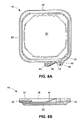
- FIGS. 6A and 6B are perspective and top views, respectively, of the tamper evident container of FIG. 1 with the pull tab and corner of the lid detached along the line of reduced strength;
- FIGS. 7A and 7B are perspective and top views, respectively, of the lid of the tamper evident container of FIG. 1 with an angled portion and a pull tab disposed adjacent the corner of the lid;
- FIGS. 8A and 8B are top and side views, respectively, of the lid of the tamper evident container of FIG. 1 with a gripping tab;
- FIGS. 9A and 9B are top and side views, respectively of the lid of the tamper evident container of FIG. 1 with first and second pull tabs and a gripping tab disposed adjacent one of the pull tabs;
- FIGS. 10A and 10B are perspective and top views of the lid of the tamper evident container of FIG. 1 having a pull tab disposed at the corner of the lid;
- FIGS. 11A-11D are perspective, side, and detail views, respectively, of a tamper evident container in accordance with the present disclosure.
- FIG. 12 is a cross-sectional view of a tamper evident container in accordance with the present disclosure.
- a bowl, tray, tub or other storage element and a corresponding lid have complimentary configurations that require permanent deformation or destruction of one or both components for removal of the lid once the lid is attached to the top of the storage element.
- the storage element may include an outwardly extending flange at a top edge of the storage element
- the lid may include outwardly and downwardly extending walls that wrap around the flange of the storage element with locking portions, such as locking nipples, tabs, tags, nubs, protrusions, or indentations, having negative angles undercutting the flange to secure the lid to the storage element.
- the lid further includes a line of reduced strength formed by a series of punctures, score lines or the like along a portion of the outwardly and/or downwardly extending walls that yields to detach a portion of the lid undercutting the flange of the bowl to allow removal of the lid from the bowl.
- the lid may further include a pull tab extending outwardly and having the line of reduced strength extending between the pull tab and a wall of the lid such that the pull tab may be grasped and pulled away from the lid to break the lid along the line of reduced strength and detach the portion undercutting the flange.
- FIG. 1 illustrates an embodiment of a tamper evident container 10 in accordance with the present disclosure.
- the container 10 includes a bowl, tray, or tub or other storage element 12 and a lid 14 configured to attach to the storage element 12 in a manner that prevents detachment of the lid 14 without a visual indication of the removal of the lid 14 , such as permanent deformation of the storage element 12 and/or the lid 14 , or the destruction of one or both of the components.
- the storage element 12 may be generally concave-shaped and include a bottom wall 16 and one or more side walls 18 . In the illustrated embodiment, the storage element 12 is generally square or rectangular with four side walls 18 .
- the storage element 12 may have other geometric configurations as necessary for the product to be stored therein and to have a desired appearance.
- the storage element 12 may be substantially circular or oval and have a single continuous side wall 18 , or include a flat portion for use in sortation of the containers or standing the containers on end for packaging or display, with the lid 14 having a corresponding shape.
- the side walls 18 extend upwardly from the bottom wall 16 and terminate at an open top edge 20 .
- the side walls 18 may include an inwardly extending ridge 19 disposed near the open top edge 20 .
- the inwardly extending ridge 19 may engage a corresponding inner slot on the lid 14 to retain the lid 14 on the storage element 12 .
- the inwardly extending ridge 19 may extend substantially continuously along the side walls 18 of the storage element 12 .
- a radial flange 22 extends outwardly at the top edge 20 of the side walls 18 and extends beyond the side walls 18 .
- the flange 22 may include a radially extending portion 24 and a downwardly extending annular portion 26 that are best illustrated in the detail view of the corner of the container 10 at FIG. 2C .
- the components of the storage element 12 may have a desired thickness in the range of 0.007′′-0.070′′, or may have varying thicknesses as necessary to contain the product disposed therein and as dictated by the characteristics from which the storage element 12 if formed, by the package size, and by other factors.
- the flange 22 may be thicker and extend radially without having separate portions 24 and 26 .
- the sidewalls 18 may further include one or more gussets or ribs to improve stability and rigidity of the storage element 12 .
- the gussets may be formed as is known in the art. For example, one or more gussets can be formed inwardly extending from the side wall and extending vertically along the side wall.
- the dimensions and geometry of the storage element 12 shown in FIGS. 2A-2C are exemplary only, and the particular dimensions and configuration of the storage element 12 may be dictated by the requirements of a particular implementation of the tamper evident container 10 .
- the same lid 14 may be attached to storage elements 12 of varying sizes and storage capacities, but with similar sized openings at their top edges 20 .
- the storage element 12 and, consequently, the container 10 and lid 14 may have shapes other than the generally square or rectangular shape with one or more curved sides, as shown.
- the container 10 may have a circular or oval opening, or have other desired shape, and may be implemented with a tamper evident lid 14 as discussed below, and such shapes are contemplated by the inventors as having use in containers in accordance with the present disclosure.
- FIGS. 3A-3C One embodiment of a tamper evident lid 14 configured to attach at the top edge 20 of the storage element 12 is illustrated in FIGS. 3A-3C .
- the lid 14 may include a generally flat or slightly concave base wall or surface 30 and an upwardly extending inner wall or walls 32 terminating at an upper edge 34 .
- the inner walls 32 are configured with a complimentary shape to the side walls 18 of the storage element 12 .
- an inner slot 33 can be disposed along the inner wall 32 .
- the inner slot 33 may correspond to and tightly engage the inwardly extending ridge 19 of the storage element 12 to provide an additional locking mechanism and retain the lid 14 on the storage element 12 .
- the ridge 19 may deflect outwardly and/or the slot 33 may deflect inwardly to allow the ridge 19 to be received in and engage the slot 33 .
- the resiliency of the material(s) from which the storage element 12 and the lid 14 are fabricated allow the components to return their normal geometries to lock the lid 14 onto the storage element 12 .
- the tight engagement between the inner slot 33 and ridge 19 may increase the rigidity of the container 10 when the lid 14 is retained on the storage element 14 , thereby securing the lid 14 on the storage element 12 against attempts to open the container in a manner that is not evident to an observer.
- the other adjacent surfaces of the lid 14 and the storage element 12 may tightly engage one another, such as the facing surfaces of the side wall 18 and the inner wall 32 , and the adjacent surfaces of the outer wall 38 and the outer edge of the flange 22 .
- the tight engagement may enhance the locking of the lid on the storage element 12 and increase the rigidity of the container 10 .
- the lid 14 includes an outwardly extending top wall 36 and a downwardly extending outer wall or walls 38 .
- the walls 32 , 36 , 38 are configured to fit over the flange 22 of the storage element 12 .
- the illustrated lid 14 having the concave base surface 30 may have particular application where the containers 10 will be stacked on top of each other.
- the base surface 30 may be substantially flat, and may even be concurrent with the top wall 36 such that the lid 14 is flat with the exception of the downwardly extending outer wall 38 , and with the inner wall 32 being omitted.
- Other configurations of the base surface 30 of the lid 14 are also contemplated by the inventors as having use in containers 10 in accordance with the present invention.
- the lid 14 is secured to the storage element 12 at the rounded corners of the flange 22 by providing inwardly protruding locking indentations 40 at each corner.
- the corners of the flange 22 may be squared off with the lid 14 being shaped accordingly.
- the indentations 40 extend inwardly at a negative angle ⁇ so that the indentations 40 wrap inwardly underneath the annular portion 26 of the flange 22 as shown in FIG. 4 .
- the negative angle ⁇ may be approximately 45°, but other angles may be used as appropriate to ensure that the lid 14 properly engages the flange 22 of the storage element 12 . As shown in FIG.
- one or more gussets 41 may be provided in the indentation 40 to enhance the strength and rigidity of the corner if desired.
- the indentations 40 and the outer wall 38 may deflect outwardly and/or the annular portion 26 of the flange 22 may deflect inwardly to allow the indentations 40 to pass over the flange 22 .
- the resiliency of the material(s) from which the storage element 12 and the lid 14 are fabricated allow the components to return their normal geometries to lock the lid 14 onto the storage element 12 .
- the lid 14 cannot be removed from the storage element 12 in a manner that is not evident to an observer. If a person attempts to lift the lid 14 over one of the corners, the indentation 40 collapses under the flange 22 as a force F is applied as shown in FIG. 5 to further secure the lid 14 to the storage element 12 .
- the lid 14 will only detach from the corner if the lid 14 and/or the flange 22 deform plastically and/or break in a manner that is visually evident. Similar visual indications of tampering with the container 10 will also be present if a person pulls on the lid 14 between the corners or presses the side walls 18 and the flange 22 of the storage element 12 inwardly.
- the lid 14 is configured so that one of the corners may be partially detached from the upper edge 34 and the corresponding corner indentation 40 to disengage from the flange 22 of the storage element 12 . Detachment of one corner is sufficient to allow the remaining indentations 40 of the lid 14 to disengage from the flange 22 and also to reengage the flange 22 to temporarily reattach the lid 14 and reclose the container 10 if desired.
- the lid 14 may include a line of reduced strength 42 , such as a line of punctures, score lines, or a continuous line of reduced thickness.
- the line of punctures may be formed by a series of full or partial punctures extending around a portion of the top wall 36 of the lid 14 at one of the corners.
- the punctures may be formed in the lid 14 at the time the lid 14 is thermoformed, blow-molded or otherwise fabricated by appropriately configuring the die or mold, or may be formed after the lid 14 is fabricated by any appropriate mechanism, such as a stamper or a serrated wheel.
- the punctures have 100% penetration through the top wall 36
- the lid 14 may have a thickness in the range of 0.007′′ to 0.070′′ to allow separation along the line of reduced strength 42 without additional deformation or destruction of the lid 14 .
- the lid 14 may have a thickness in the range of 0.010′′ to 0.040′′, and in some embodiments, the desired thickness may be in the range of 0.013′′ to 0.015′′.
- the line of reduced strength 42 may be formed with less than full penetration if the spacing and size of the punctures are adjusted accordingly to provide detachment of the corner without permanent deformation or destruction of other portions of the lid 14 .
- the line of reduced strength 42 may also be formed as a series of score lines by blade scoring the lid 14 . Blade scoring can be performed with partial penetration, such as in the range of 60% to 80% penetration, or with full penetration through the top wall 36 of the lid 14 .
- a continuous blade score with full penetration through the lid 14 may be performed with intermittent interruptions or bridges in the score line being provided to hold the corner in place until the user detaches the corner to open the container 10 .
- the bridges can be formed with partial penetration or no penetration through the top wall 36 of the lid 14 .
- the line of reduced strength 42 can be formed to include punctures that partially penetrate the top wall 36 and bridges that do not penetrate the top wall 36 , punctures that fully penetrate the top wall 36 and bridges that do not penetrate the top wall 36 , punctures that partially penetrate the top wall 36 and bridges that partially penetrate the top wall 36 , and/or punctures that fully penetrate the top wall 36 and bridges that partially penetrate the top wall 36 .
- the distance between the bridges may range from about 0.05 inches to about 2.0 inches and the length of the bridge may fall within the range of about 0.002 inches to about 0.090 inches.
- Those skilled in the art will understand that other mechanisms for providing the line of reduced strength 42 , such as mechanical or laser scoring, or configuring the dies or molds to form the line of reduced strength 42 in the walls 36 , 38 of the lid 14 that will separate to detach the outer wall 38 , may be used to define the detachable portion of the lid 14 and are contemplated by the inventors as having use in tamper evident containers 10 in accordance with the present disclosure.
- the lid 14 may include a pull tab 44 attached to a portion of the outer wall 38 of the lid 14 proximate the corner having the line of reduced strength 42 .
- the pull tab 44 may be an outward extension of the top wall 36 , or may be angled downwardly from the top wall 36 along the outer wall 38 such that the end of the tab 44 is concurrent with a bottom edge of the outer wall 38 .
- the pull tab 44 slopes downwardly at an angle ⁇ in the range of 5° to 30°, such as at the illustrated angle ⁇ having an approximate value of 17.5°.
- the pull tab can also have other geometries, such as, for example, a non-planar or curved surface.
- the line of reduced strength 42 may extend from the corner of the lid 14 along the pull tab 44 proximate the point of intersection of the pull tab 44 with the outer wall 38 .
- the pull tab 44 may include an arrow 46 formed thereon, or applied after the lid 14 is formed, and pointing in the direction that the pull tab 44 is to be pulled to detach the pull tab 44 and the corner along the line of reduced strength 42 .
- the punctures, score lines, or the like cause the pull tab 44 to detach at the end of the pull tab 44 and then along the line of reduced strength 42 around the corner of the lid 14 .
- the top wall 36 proximate the end of the line of reduced strength 42 may plastically deform or detach such that the corner and pull tab 44 remain disposed away from the side of the container 10 to provide visual evidence of the opening of the container 10 as shown in FIGS. 6A and 6B .
- the adjacent corners may be pulled outwardly away from the flange 22 and lifted over the flange 22 to remove the lid 14 from the storage element 12 .
- the embodiment illustrated in FIGS. 7A and 7B includes a pull tab 44 to facilitate detachment of the corner of the lid 14 along the line of reduced strength 42 .
- the pull tab 44 may be an outward extension of the outer wall 38 , disposed at the corner having the line of reduced strength 42 and concurrent with a bottom edge of the outer wall 38 .
- An angled portion 47 may be disposed along the outer wall 38 to facilitate detachment of the corner of the lid 14 using the pull tab 44 .
- the angled portion 47 may slope downwardly from the top wall 36 along the outer wall 38 such that the end of the angled portion 47 is concurrent with the bottom edge of the outer wall 38 and the pull tab 44 .
- the angled portion 47 may be sloped downwardly at an angle in a range of 10° to 30°.
- the line of reduced strength 42 may extend from the corner of the lid 14 along the angled portion 47 proximate the point of intersection of the angled portion 47 with the outer wall 38 .
- the pull tab 44 can include indicia to assist the user in detaching the corner, such as for example, the word “lift” to indicate that the pull tab 44 is to be lifted to detach the pull tab 44 and the corner along the line of reduced strength 42 .
- the pull tab 44 may also include a gripping pattern formed on the pull tab 44 to further aid the user in gripping and detaching the pull tab 44 .
- the top wall 36 proximate the end of the line of reduced strength 42 may plastically deform or detach such that the corner and pull tab 44 remain disposed away from the side of the container 10 to provide visual evidence of the opening of the container 10 .
- the adjacent corners may be pulled outwardly away from the flange 22 and lifted over the flange 22 to remove the lid 14 from the storage element 12 .
- the lid 14 can further include a gripping tab 48 attached to a portion of the outer wall 38 of the lid 14 .
- the gripping tab 48 can be an outward extension of a bottom edge of the outer wall 38 of the lid 14 .
- the gripping tab 48 can facilitate detachment of the corner of the lid 14 by providing the user with a secondary surface to grasp while detaching the corner using the pull tab 44 .
- the gripping tab 48 can be provided along any portion of the outer wall 38 of the lid 14 .
- the gripping tab 48 can be provided proximate the pull tab 44 .
- the gripping tab 48 may include the number “2” or other indicia 49 formed thereon, or applied after the lid 14 is formed, indicating to the user that the tab is a gripping tab 48 to be held during opening of the container 10 .
- the pull tab 44 may include a number “1” or other indicia 46 formed thereon, or applied after the lid 14 is formed, indicating to the user that the tab is the pull tab 44 .
- the gripping tab 48 may also include a gripping pattern formed on the pull tab 44 to further aid the user in gripping and holding the gripping tab 48 when detaching the pull tab 44 .
- FIGS. 9A and 9B illustrates a further alternative embodiment of the lid 14 wherein a second pull tab 45 may be provided that outwardly extends from the outer wall 38 , such that first and second pull tabs 44 , 45 are disposed on opposite sides of the corner having the line of reduced strength 42 at either end of the line 42 .
- the second pull tab 45 may be an outward extension of the top wall 36 , or may be angled downwardly from the top wall 36 along the outer wall 38 .
- the lid 14 can be configured so that one of the corners may be partially or fully detached from the upper edge 34 and the corresponding corner indentation 40 disengaged from the flange 22 of the storage element 12 using either the first or second pull tab 44 , 45 .
- a line of reduced strength 42 may extend from the corner of the lid 14 along the each of the first and second pull tabs 44 , 45 proximate the point of intersection of the pull tabs 44 , 45 with the outer wall 38 .
- the pull tabs 44 , 45 may include arrows 46 formed thereon, or applied after the lid 14 is formed, and pointing in the direction that the pull tabs 44 , 45 are to be pulled to detach the pull tabs 44 , 45 and the corner along the line of reduced strength 42 .
- the pull tabs 44 , 46 may also include a gripping pattern formed on the pull tabs 44 , 45 to further aid the user in gripping and detaching the pull tabs 44 , 45 .
- Either pull tab 44 , 45 can be grasped by the user and pulled to partially or fully detach the pull tab 44 and the corner along the line of reduced strength 42 .
- the user may pull either the first or second pull tab 44 , 45 until the pull tab 44 , 45 and the corner detach along the line of reduced strength 42 , but before the remaining pull tab 44 , 45 detaches.
- the user may pull the first or second pull tab 44 , 45 , until first or second pull tab 44 , 45 detaches along the line of reduced strength 42 around the corner of the lid 14 , and continue to pull the first or second pull tab 44 , 45 to detach the remaining pull tab 44 , 45 along the line of reduced strength 42 .
- the user can also pull both the first and second pull tabs 44 , 45 causing both pull tabs 44 , 45 to detach from at the end of each of the pull tabs 44 , 45 and then along the line of reduced strength 42 around the corner of the lid 14 .
- the corner of the lid 14 is completely detached from the container 10 to provide visual evidence of the opening of the container 10 .
- two lines of reduced strength 42 can be provided that extend around the corner but do not intersect.
- the remaining pull tab 44 , 45 , and consequently the corner remains attached to the lid 14 .
- the lid 14 having first and second pull tabs 44 , 45 can further include a gripping tab 48 as described above with reference to FIG. 9 , to further facilitate opening of the container 10 .
- the gripping tab 48 can be located adjacent to one or both of the first or second pull tabs 44 , 45 , outwardly extending from the portion of the outer wall 38 from which the pull tab 44 , 45 extends.
- the gripping tab 48 may be disposed in similar locations on the lids 14 having only a single pull tab 44 .
- the lid 14 can include a pull tab 50 disposed at the corner of the lid 14 that may be partially detached and lifted outwardly and/or upwardly to disengage the indentation 40 located at the corner from the corresponding corner of the storage element 12 .
- two lines of reduced strength 52 , 54 may be provided on opposite sides of the pull tab 50 and may extend along the outer wall 38 portions of the top wall 36 . When the user grasps and pulls the pull tab 50 outward and upward, the lines of reduced strength 52 , 54 may cause the pull tab 50 to detach along the lines of reduced strength 52 , 54 to partially detach the corner of the lid 14 .
- the top wall 36 proximate the lines of reduced strength 52 , 54 may plastically deform or detach such that the indentation 40 disengages from the flange 22 and the corner and the pull tab 50 remains disposed away from the side of the container 10 to provide visual evidence of the opening of the container 10 .
- the adjacent corners may be pulled outwardly away from the flange 22 and lifted over the flange 22 to remove the lid 14 from the storage element 12 . If the corner is only partially detached, the corner may be pulled or pressed back down against the corresponding corner of the storage element 12 .
- the indentation 40 disposed at the corner may reengage with the storage element 12 to reseal the container 10 .
- a third line of reduced strength 56 may be provided along the corner, which may aid in preventing a user from using the pull tab 50 to disengage the indentation 40 without detaching the corner along the lines of reduced strength 52 , 54 .
- the third line of reduced strength 56 may be disposed on the top wall 36 of the lid 14 along the corner.
- the third line of reduced strength 56 may be connected to or may be an extension of one or both of the lines of reduced strength 52 , 54 .
- the third line of reduced strength 56 may be disposed on the pull tab 50 so that a portion of the pull tab 50 detaches along the third line of reduced strength 56 , thereby preventing the pull tab 50 from providing leverage for disengaging the lid 14 without detaching the corner along the lines of reduced strength 52 , 56 .
- the container 10 may have a round opening, and a round lid 14 may be provided.
- the lid 14 may have a series of indentations 40 spaced around the outer wall 38 of the lid 14 .
- the lid 14 may have a single indentation 40 around all of or substantially the entire outer wall 38 . In either configuration, the indentation(s) 40 prevent the lid 14 from being removed from the storage element 12 without evidence of the removal.
- the lid 14 also includes a line of reduced strength 42 and a pull tab 44 as discussed above.
- the line of reduced strength 42 may extend in the range of 30° to 120°, and in some embodiments in the range of 60° to 90° around the circumference of the top wall 36 of the lid 14 to ensure a sufficient amount of detachment of the indentation(s) 40 to allow the lid 14 to be removed from the storage element 12 .
- FIGS. 11A-11C illustrate an alternative embodiment of a tamper evident container 110 having a storage element 112 and a lid 114 .
- the lid 114 may include an indentation 140 that may be formed continuously along the outer wall 138 .
- the indentation 140 may be formed as described above, along only the corners of the lid 114 .
- the indentation 140 extend inwardly at a negative angle ⁇ so that the indentation 140 wrap inwardly underneath the flange 122 of the storage element 112 , as is best illustrated in FIG. 11C .
- the indentation 140 functions as described above to secure the lid 114 on the storage element 112 so that the lid 114 cannot be removed in a manner that is not evident to an observer.
- the indentation 140 assists in ensuring that the lid 114 remains locked on the storage element 112 at the center portions of the sidewall 118 of the storage element 112 . This may be advantageous in securing a lid 114 of a larger container having increased sidewall 118 lengths between the corners.
- an internal lock may be formed by the engagement of a ridge 119 of the storage element 112 and a slot 133 of the lid 114 in a similar manner as described above.
- the lid 114 may be secured to the storage element 112 by an internal lock formed by a locking portion 160 of a side wall 118 of the storage element 112 and a locking portion 162 of the inner wall 132 of the lid 114 .
- the locking portion 160 of a side wall 118 of the storage element 112 may be disposed adjacent the top edge 120 and angled outwardly from the center of the storage element 112 as it extends downwardly from the flange 122 .
- the locking portion 162 of the inner wall 132 of the lid 114 may be disposed adjacent the upper edge 134 at a location corresponding to the locking portion 160 of the storage element 112 , and may be angled outwardly from the center of the lid 114 as it extends downward from the top wall 136 at an angle corresponding to the angle of the locking portion 160 of the side wall 118 of the storage element 112 .
- the locking portion 162 of the inner wall 132 may be received and engaged by the locking portion 160 of the side wall 118 of the storage element 112 to retain the lid 114 on the storage element 112 such that the lid 114 cannot be removed from the storage element 112 without permanently deforming at least one of the lid 114 and the storage element 112
- the top wall 136 of lid 114 may extend over the flange 122 of the storage element 112 to further prevent a user from disengaging the internal lock in a manner that is not evident to an observer.
- one or more of the walls 132 , 136 , 138 can include one or more gussets 137 to improve the stability and rigidity of the lid 114 , and further prevent the lid 114 from being removed without first detaching the pull tab 144 and corresponding corner along the line of reduced strength 142 .
- the embodiment illustrated in FIGS. 11A-11C further illustrates the storage element 112 having one or more portions 141 disposed on and outwardly extending from an exterior portion of the side wall 118 in various locations. The portions 141 may provide a foot upon which the container 10 can be propped up on the portions and consequently a side of the container 110 .
- the portions 141 may further improve the stiffness of the storage element 112 and aid in retaining the lid 114 on the storage element 112 by preventing the portions of the side walls 118 from buckling when forces are applied to the adjacent portions of the side wall 118 , or from being forced inward in an attempt to reach under the top wall 136 of the lid 114 to disengage the lid 114 from the storage clement 112 .
- the portions of the side wall 118 having the curved portion 141 is forced inward, the curved portion 141 forces the flange 122 into tighter engagement with top and outer walls 136 , 138 of the lid 114 .
- the lid 114 of the container 110 of FIGS. 11A-11C may also include a raised base wall 130 in contrast to the flat or lowered base wall 30 of lid 14 .
- the raised base wall 130 may be used to increase the volume of the container 110 and the bottom of the storage element 112 may have a complimentary shape to promote stacking of the containers 110 .
- a center portion of the raised base wall 130 may also be recessed to provide a surface for receiving the bottom of the storage element 112 to promote stacking of the containers 110 .
- the base wall 130 may include a raised portion 131 a and a flange 131 b that extends outwardly toward the inner wall 132 .
- the flange 131 b can be angled downwardly from a bottom edge of the raised portion 131 a to the inner wall 132 . When disposed at a downward angle, the flange 131 b may further secure the lid 114 against the storage element 112 . When a downward force is applied to the lid 114 in an attempt to open the container 110 by collapsing the lid 114 , the flange 131 b may flatten and extend toward the inner wall 132 , thereby forcing the inner wall 132 of the lid 114 into tighter engagement against the side wall 118 of the storage element 112 , and further securing the lid 114 on the storage element 112 .
- FIG. 12 illustrates an alternative embodiment of a tamper evident container 210 having a storage element 212 and a lid 214 .
- an internal lock may be formed by the engagement of a ridge 219 of the storage element 212 and a slot 233 of the lid 214 in a similar manner as described above.
- the ridge 219 may extend along an internal surface of the side wall 218 of the storage element 212 .
- the ridge 219 may projected inwardly from the side wall 218 to a width in a range of 0.01′′ to 0.2′′.
- the ridge 219 may have a substantially half-circle cross-sectional shape, a substantially rectangular cross-sectional shape, a substantially triangular cross-sectional shape, or other desired cross-sectional shapes.
- the inner slot 33 may be disposed along the inner wall 32 .
- the inner slot 233 may have a depth corresponding to or slightly less than the width of the ridge 219 so as to provide a tight engagement between the inner slot 233 and the ridge 219 .
- the inner slot 233 may also include a cross-sectional shape substantially corresponding to the cross-sectional shape of the ridge 219 . Other configurations of the slot 233 and ridge 219 are contemplated.
- the slot 233 may formed on the storage element 212
- the ridge 219 may be formed on the lid 214 .
- the tight engagement between the inner slot 233 and ridge 219 may increase the rigidity of the container 210 when the lid 214 is retained on the storage element 214 .
- the other adjacent surfaces of the lid 214 and the storage element may tightly engage one another, such as the facing surfaces of the side wall 218 and the inner wall 232 , and the adjacent surfaces of the outer wall 238 and the outer edge of the glance 222 .
- the tight engagement may enhance the locking of the lid on the tray and increase the rigidity of the container 210 .
- the container 210 may further include an indentation formed as described above, which may further ensure that the lid 214 remains locked on the storage element 214 .
- the ridge 219 may deflect outwardly and/or the slot 233 may deflect inwardly to allow the ridge 219 to be received in and engaged by the slot 233 .
- the resiliency of the material(s) from which the storage element 212 and the lid 214 are fabricated allow the components to return their normal geometries to lock the lid 214 onto the storage element 212 .
- the outwardly extending top wall 236 and downwardly extending outer wall 238 of the lid 214 may extend over the flange 222 of the storage element 212 , which may prevent a user from reaching under the lid and pulling on the flange 222 to separate the flange 222 from the top wall 236 and disengage the ridge 219 from the slot 233 to open the container in a manner not evident to an observer.
- the downwardly extending outer wall 238 may further include an outwardly extending portion disposed at a bottom edge of the outer wall 238 .
- the container 210 may further include a line of reduced strength 242 , such as a line of punctures, score lines, a continuous line of reduced thickness, a blade scoring line having punctures and bridges adjacent the punctures, and combinations thereof.
- the line of reduced strength 242 can be formed as described above and can extend along a portion of the top and outer walls 236 , 238 at one of the corners, along one of the sides, or a combination thereof, to allow for detachment of the portion, and thereby allow a user to reach under the lid and access the flange 222 to disengage the ridge 219 from the slot 233 and, consequently, the lid 214 from the storage element 214 .
- the lid 214 may include a pull tab 244 attached to a portion of the outer wall 238 of the lid 214 proximate the portion of the outer wall and/or top wall having the line of reduced strength 242 .
- the punctures, score lines, or the like cause the pull tab 244 to detach at the end of the pull tab 244 and then along the line of reduced strength 242 along the top and/or outer wall 236 , 238 .
- Detachment of a portion of the top and/or outer wall 236 , 238 may then allow a user reach under the top wall 236 of the lid 214 to disengage the ridge 219 of the storage element 212 from the slot 233 of the lid 214 , and thereby detach the lid 214 from the storage element 212 .
- the detachment of the portion of the top and/or outer wall 236 , 238 may also allow the user access to a portion of the storage element 212 which may be grasped and provide leverage for disengaging the lid 214 from the storage element 212 .
Abstract
Description
Claims (36)
Priority Applications (2)
| Application Number | Priority Date | Filing Date | Title |
|---|---|---|---|
| US12/350,903 US8757416B2 (en) | 2008-01-08 | 2009-01-08 | Tamper evident container |
| US12/610,983 US20100084401A1 (en) | 2008-01-08 | 2009-11-02 | Tamper evident container |
Applications Claiming Priority (2)
| Application Number | Priority Date | Filing Date | Title |
|---|---|---|---|
| US1977708P | 2008-01-08 | 2008-01-08 | |
| US12/350,903 US8757416B2 (en) | 2008-01-08 | 2009-01-08 | Tamper evident container |
Related Child Applications (1)
| Application Number | Title | Priority Date | Filing Date |
|---|---|---|---|
| US12/610,983 Continuation-In-Part US20100084401A1 (en) | 2008-01-08 | 2009-11-02 | Tamper evident container |
Publications (2)
| Publication Number | Publication Date |
|---|---|
| US20090173738A1 US20090173738A1 (en) | 2009-07-09 |
| US8757416B2 true US8757416B2 (en) | 2014-06-24 |
Family
ID=40843748
Family Applications (1)
| Application Number | Title | Priority Date | Filing Date |
|---|---|---|---|
| US12/350,903 Active 2032-03-01 US8757416B2 (en) | 2008-01-08 | 2009-01-08 | Tamper evident container |
Country Status (2)
| Country | Link |
|---|---|
| US (1) | US8757416B2 (en) |
| WO (1) | WO2009089389A1 (en) |
Cited By (15)
| Publication number | Priority date | Publication date | Assignee | Title |
|---|---|---|---|---|
| US9278786B2 (en) | 2011-03-22 | 2016-03-08 | Smart-Tab, Llc | Containers with tamper-evident features |
| US9365331B2 (en) | 2010-08-26 | 2016-06-14 | Dart Container Corporation | Tamper evident container |
| US9580219B2 (en) | 2015-06-30 | 2017-02-28 | Anchor Packaging | Tamper evident plastic food container |
| US9624009B2 (en) | 2010-08-26 | 2017-04-18 | Dart Container Corporation | Tamper evident container |
| US20170341841A1 (en) * | 2016-05-31 | 2017-11-30 | Poni Greentek Co., Ltd. | Plastic package with an open reminder |
| US20180057223A1 (en) * | 2015-06-30 | 2018-03-01 | Anchor Packaging, Inc. | Tamper evident plastic food container |
| US10220985B2 (en) | 2016-10-28 | 2019-03-05 | Genpak, Llc | Tamper-evident container with a tabbed hinge |
| US10351310B2 (en) | 2016-10-28 | 2019-07-16 | Genpak, Llc | Tamper-evident container with a bump near a tabbed hinge |
| US10384843B2 (en) | 2017-01-31 | 2019-08-20 | Smart-Tab, Llc | Pull-tab tamper evident container |
| US10889413B2 (en) | 2016-10-28 | 2021-01-12 | Genpak, Llc | Tamper-evident container with a tab extending beyond a hinge |
| US10894635B2 (en) | 2016-10-28 | 2021-01-19 | Genpak, Llc | Tamper-evident container with a wide tab extending beyond a hinge |
| US11479389B2 (en) | 2020-05-20 | 2022-10-25 | Anchor Packaging, Llc | Tamper evident plastic food container |
| US11479392B2 (en) | 2020-05-20 | 2022-10-25 | Anchor Packaging, Llc | Tamper evident plastic food container |
| US11535428B2 (en) | 2020-07-16 | 2022-12-27 | Placon Corporation | Tamper evident reclosable container |
| US11794966B2 (en) | 2021-12-06 | 2023-10-24 | Tekni-Plex, Inc. | Food container with tamper-proof hinged closure |
Families Citing this family (7)
| Publication number | Priority date | Publication date | Assignee | Title |
|---|---|---|---|---|
| EP2554486A1 (en) * | 2011-08-04 | 2013-02-06 | Nestec S.A. | A packaging with a spout for flowable products |
| TWM454389U (en) * | 2013-01-07 | 2013-06-01 | Wei Mon Ind Co Ltd | Tamper evident container |
| US9187209B1 (en) * | 2013-07-05 | 2015-11-17 | Highland Packaging Solutions, Inc. | Tamper evident container having tear tab and hinged lid |
| USD763105S1 (en) * | 2013-11-11 | 2016-08-09 | Clear Lam Packaging, Inc. | Container |
| USD786674S1 (en) * | 2015-08-31 | 2017-05-16 | Cvs Pharmacy, Inc. | Bottle cap |
| US10451335B2 (en) * | 2016-03-07 | 2019-10-22 | Phase Change Energy Solutions, Inc. | Product transport containers |
| CN206842057U (en) * | 2017-03-07 | 2018-01-05 | 歌乐电磁(深圳)有限公司 | Packing box |
Citations (21)
| Publication number | Priority date | Publication date | Assignee | Title |
|---|---|---|---|---|
| US4202455A (en) * | 1977-11-16 | 1980-05-13 | Three Sisters Ranch Enterprises | Molded plastic container for use with a cap having inner and outer skirts |
| US4836407A (en) * | 1987-08-04 | 1989-06-06 | Cpc-Rexcel, Inc. | Tamper-evident, differential pressure-thermoformed lidded plastic container |
| US4854472A (en) | 1988-06-10 | 1989-08-08 | Plastic Technologies, Inc. | Tamper resistant wide mouth package with dynamic seal |
| US4893452A (en) * | 1987-08-04 | 1990-01-16 | Cpc-Rexel, Inc. | Method for making a tamper-evident, differential pressure-thermoformed lidded plastic container |
| WO1998002362A2 (en) | 1996-07-16 | 1998-01-22 | Alexandre Rey Silveira | A tamper-proof package having a temper-indicating seal |
| JPH11312904A (en) | 1997-11-05 | 1999-11-09 | Murata Mfg Co Ltd | Filter, duplexer and communication equipment |
| US20030189047A1 (en) | 2000-07-19 | 2003-10-09 | Mchutchinson Roy Neil | Tamper proof hinged lid container |
| US20040020929A1 (en) | 2002-04-22 | 2004-02-05 | Morris Glenn H. | Open ended container with tamper indicator |
| US6899245B1 (en) | 2003-07-14 | 2005-05-31 | James L. Nelson | Container with tamper resistant lid |
| EP1559656A1 (en) | 2004-01-28 | 2005-08-03 | Isap Omv Group S.P.A. | Container and lid with tear-away tamper resistant sealing strip |
| US20060006178A1 (en) | 2004-07-08 | 2006-01-12 | Foldesi Steve Sr | Tamper-indicating food container lid |
| US20060060578A1 (en) | 2004-09-03 | 2006-03-23 | Church John R | Secure locking container |
| US20070045317A1 (en) | 2005-08-31 | 2007-03-01 | Rosender Adam K | Tamper evident thermoformed containers |
| US7228979B2 (en) * | 1997-10-30 | 2007-06-12 | International Plastics And Equipment Corp. | Snap-on screw-off closure with retaining member for tamper-indicating band |
| US20070138180A1 (en) | 2005-12-21 | 2007-06-21 | Terry Vovan | Enhanced tamper evident bowl with blocked tab |
| US20080302798A1 (en) * | 2007-06-08 | 2008-12-11 | Foldesi Sr Steve | Single tab lid |
| US20100051620A1 (en) * | 2008-08-29 | 2010-03-04 | Parikh Samir R | Tamper-evident container |
| US20100108680A1 (en) * | 2006-06-05 | 2010-05-06 | Terry Vovan | Enhanced tamper evident container with tear-apart parts |
| US8127961B2 (en) * | 2007-11-10 | 2012-03-06 | Pwp Industries | Double ribbed secure container |
| US8157123B2 (en) * | 2005-02-23 | 2012-04-17 | The Glad Products Company | Container |
| US8254242B2 (en) * | 2008-05-02 | 2012-08-28 | Princeton University | System and method for initial ranging in wireless communication systems |
Family Cites Families (1)
| Publication number | Priority date | Publication date | Assignee | Title |
|---|---|---|---|---|
| TW440536B (en) * | 1998-05-12 | 2001-06-16 | Maeda Seisakusho | Sealing means for a plastics container and lid, and to a product using such sealing means |
-
2009
- 2009-01-08 US US12/350,903 patent/US8757416B2/en active Active
- 2009-01-08 WO PCT/US2009/030496 patent/WO2009089389A1/en active Application Filing
Patent Citations (22)
| Publication number | Priority date | Publication date | Assignee | Title |
|---|---|---|---|---|
| US4202455A (en) * | 1977-11-16 | 1980-05-13 | Three Sisters Ranch Enterprises | Molded plastic container for use with a cap having inner and outer skirts |
| US4836407A (en) * | 1987-08-04 | 1989-06-06 | Cpc-Rexcel, Inc. | Tamper-evident, differential pressure-thermoformed lidded plastic container |
| US4893452A (en) * | 1987-08-04 | 1990-01-16 | Cpc-Rexel, Inc. | Method for making a tamper-evident, differential pressure-thermoformed lidded plastic container |
| US4854472A (en) | 1988-06-10 | 1989-08-08 | Plastic Technologies, Inc. | Tamper resistant wide mouth package with dynamic seal |
| WO1998002362A2 (en) | 1996-07-16 | 1998-01-22 | Alexandre Rey Silveira | A tamper-proof package having a temper-indicating seal |
| US7228979B2 (en) * | 1997-10-30 | 2007-06-12 | International Plastics And Equipment Corp. | Snap-on screw-off closure with retaining member for tamper-indicating band |
| JPH11312904A (en) | 1997-11-05 | 1999-11-09 | Murata Mfg Co Ltd | Filter, duplexer and communication equipment |
| US20030189047A1 (en) | 2000-07-19 | 2003-10-09 | Mchutchinson Roy Neil | Tamper proof hinged lid container |
| US20040020929A1 (en) | 2002-04-22 | 2004-02-05 | Morris Glenn H. | Open ended container with tamper indicator |
| US6899245B1 (en) | 2003-07-14 | 2005-05-31 | James L. Nelson | Container with tamper resistant lid |
| EP1559656A1 (en) | 2004-01-28 | 2005-08-03 | Isap Omv Group S.P.A. | Container and lid with tear-away tamper resistant sealing strip |
| US20060006178A1 (en) | 2004-07-08 | 2006-01-12 | Foldesi Steve Sr | Tamper-indicating food container lid |
| US20060060578A1 (en) | 2004-09-03 | 2006-03-23 | Church John R | Secure locking container |
| US8157123B2 (en) * | 2005-02-23 | 2012-04-17 | The Glad Products Company | Container |
| US20070045317A1 (en) | 2005-08-31 | 2007-03-01 | Rosender Adam K | Tamper evident thermoformed containers |
| US20070138180A1 (en) | 2005-12-21 | 2007-06-21 | Terry Vovan | Enhanced tamper evident bowl with blocked tab |
| US8056750B2 (en) * | 2005-12-21 | 2011-11-15 | Pwp Industries | Advanced tamper evident bowl |
| US20100108680A1 (en) * | 2006-06-05 | 2010-05-06 | Terry Vovan | Enhanced tamper evident container with tear-apart parts |
| US20080302798A1 (en) * | 2007-06-08 | 2008-12-11 | Foldesi Sr Steve | Single tab lid |
| US8127961B2 (en) * | 2007-11-10 | 2012-03-06 | Pwp Industries | Double ribbed secure container |
| US8254242B2 (en) * | 2008-05-02 | 2012-08-28 | Princeton University | System and method for initial ranging in wireless communication systems |
| US20100051620A1 (en) * | 2008-08-29 | 2010-03-04 | Parikh Samir R | Tamper-evident container |
Cited By (18)
| Publication number | Priority date | Publication date | Assignee | Title |
|---|---|---|---|---|
| US9365331B2 (en) | 2010-08-26 | 2016-06-14 | Dart Container Corporation | Tamper evident container |
| US9409683B2 (en) | 2010-08-26 | 2016-08-09 | Dart Container Corporation | Tamper evident container |
| US9624009B2 (en) | 2010-08-26 | 2017-04-18 | Dart Container Corporation | Tamper evident container |
| US9278786B2 (en) | 2011-03-22 | 2016-03-08 | Smart-Tab, Llc | Containers with tamper-evident features |
| US10450112B2 (en) * | 2015-06-30 | 2019-10-22 | Anchor Packaging, Llc | Tamper evident plastic food container |
| US9580219B2 (en) | 2015-06-30 | 2017-02-28 | Anchor Packaging | Tamper evident plastic food container |
| US20180057223A1 (en) * | 2015-06-30 | 2018-03-01 | Anchor Packaging, Inc. | Tamper evident plastic food container |
| US20170341841A1 (en) * | 2016-05-31 | 2017-11-30 | Poni Greentek Co., Ltd. | Plastic package with an open reminder |
| US9868576B2 (en) * | 2016-05-31 | 2018-01-16 | Poni Greentek Co., Ltd. | Plastic package with an open reminder |
| US10220985B2 (en) | 2016-10-28 | 2019-03-05 | Genpak, Llc | Tamper-evident container with a tabbed hinge |
| US10351310B2 (en) | 2016-10-28 | 2019-07-16 | Genpak, Llc | Tamper-evident container with a bump near a tabbed hinge |
| US10889413B2 (en) | 2016-10-28 | 2021-01-12 | Genpak, Llc | Tamper-evident container with a tab extending beyond a hinge |
| US10894635B2 (en) | 2016-10-28 | 2021-01-19 | Genpak, Llc | Tamper-evident container with a wide tab extending beyond a hinge |
| US10384843B2 (en) | 2017-01-31 | 2019-08-20 | Smart-Tab, Llc | Pull-tab tamper evident container |
| US11479389B2 (en) | 2020-05-20 | 2022-10-25 | Anchor Packaging, Llc | Tamper evident plastic food container |
| US11479392B2 (en) | 2020-05-20 | 2022-10-25 | Anchor Packaging, Llc | Tamper evident plastic food container |
| US11535428B2 (en) | 2020-07-16 | 2022-12-27 | Placon Corporation | Tamper evident reclosable container |
| US11794966B2 (en) | 2021-12-06 | 2023-10-24 | Tekni-Plex, Inc. | Food container with tamper-proof hinged closure |
Also Published As
| Publication number | Publication date |
|---|---|
| WO2009089389A1 (en) | 2009-07-16 |
| US20090173738A1 (en) | 2009-07-09 |
Similar Documents
| Publication | Publication Date | Title |
|---|---|---|
| US8757416B2 (en) | Tamper evident container | |
| US20100084401A1 (en) | Tamper evident container | |
| US10384843B2 (en) | Pull-tab tamper evident container | |
| US8672166B2 (en) | Resealable food container with lid having a tamper evident tear away band | |
| US8251242B2 (en) | Tamper-evident container with extended band | |
| US7992743B2 (en) | Edge-tearing tamper-evident container | |
| US11530079B2 (en) | Tamper-resistant and tamper-evident containers | |
| US20150028033A1 (en) | Tamper Evident Packaging | |
| US9944436B2 (en) | Tamper-evident container and method | |
| US5002198A (en) | Tamper evident closure for container | |
| US20180057223A1 (en) | Tamper evident plastic food container | |
| US9624009B2 (en) | Tamper evident container | |
| CN108861029B (en) | Tamper-evident plastic food container | |
| US20100140267A1 (en) | Container with hang tab and method of forming the same | |
| EP1868909A1 (en) | Container closure with deformable region in skirt to allow pivoting | |
| US20100224630A1 (en) | Tamper Evident Container With Pull Tab | |
| US20110174819A1 (en) | Tamper evident container | |
| US10723524B2 (en) | Tamper-evident lock for thermoformed container | |
| US10669078B2 (en) | Tamper-evident container and method | |
| US8322555B2 (en) | Resealable tamper-evident container assembly and lid | |
| US11505373B2 (en) | Receptacle having a tamper resistant locking mechanism for produce and foodstuff | |
| US11794966B2 (en) | Food container with tamper-proof hinged closure | |
| US20180079568A1 (en) | Plastic packaging with tamper evidence | |
| US20230133280A1 (en) | Tamper-Resistant and Tamper-Evident Containers | |
| CA2720376C (en) | Tamper-evident container with extended band |
Legal Events
| Date | Code | Title | Description |
|---|---|---|---|
| AS | Assignment |
Owner name: CLEAR LAM PACKAGING, INC., ILLINOIS Free format text: ASSIGNMENT OF ASSIGNORS INTEREST;ASSIGNORS:GOLOTA, GEORGE;DROZEK, MICHAEL;SANFILIPPO, JAMES J.;AND OTHERS;REEL/FRAME:022312/0178;SIGNING DATES FROM 20090114 TO 20090128 Owner name: CLEAR LAM PACKAGING, INC., ILLINOIS Free format text: ASSIGNMENT OF ASSIGNORS INTEREST;ASSIGNORS:GOLOTA, GEORGE;DROZEK, MICHAEL;SANFILIPPO, JAMES J.;AND OTHERS;SIGNING DATES FROM 20090114 TO 20090128;REEL/FRAME:022312/0178 |
|
| AS | Assignment |
Owner name: HARRIS N.A., AS AGENT, ILLINOIS Free format text: SECURITY AGREEMENT;ASSIGNOR:CLEAR LAM PACKAGING, INC.;REEL/FRAME:025877/0424 Effective date: 20110228 |
|
| AS | Assignment |
Owner name: D&W FINE PACK ACQUISITION (II) LLC, SOUTH CAROLINA Free format text: ASSIGNMENT OF ASSIGNORS INTEREST;ASSIGNOR:CLEAR LAM PACKAGING, INC.;REEL/FRAME:028230/0060 Effective date: 20120515 |
|
| AS | Assignment |
Owner name: D&W FINE PACK LLC, ILLINOIS Free format text: ASSIGNMENT OF ASSIGNORS INTEREST;ASSIGNOR:D&W FINE PACK ACQUISITION (II) LLC;REEL/FRAME:032528/0857 Effective date: 20140319 |
|
| STCF | Information on status: patent grant |
Free format text: PATENTED CASE |
|
| AS | Assignment |
Owner name: D&W FINE PACK LLC, ILLINOIS Free format text: RELEASE BY SECURED PARTY;ASSIGNOR:BMO HARRIS BANK N.A. F/K/A HARRIS N.A.;REEL/FRAME:034674/0454 Effective date: 20150109 |
|
| AS | Assignment |
Owner name: D&W FINE PACK ACQUISITION (II) LLC, ILLINOIS Free format text: RELEASE BY SECURED PARTY;ASSIGNOR:WELLS FARGO BANK, NATIONAL ASSOCIATION;REEL/FRAME:034859/0809 Effective date: 20150115 Owner name: WELLS FARGO BANK, NATIONAL ASSOCIATION, ILLINOIS Free format text: SECURITY INTEREST;ASSIGNORS:D&W FINE PACK HOLDINGS LLC;D&W FINE PACK LLC;REEL/FRAME:034861/0938 Effective date: 20150115 |
|
| FEPP | Fee payment procedure |
Free format text: PAYOR NUMBER ASSIGNED (ORIGINAL EVENT CODE: ASPN); ENTITY STATUS OF PATENT OWNER: LARGE ENTITY |
|
| MAFP | Maintenance fee payment |
Free format text: PAYMENT OF MAINTENANCE FEE, 4TH YEAR, LARGE ENTITY (ORIGINAL EVENT CODE: M1551) Year of fee payment: 4 |
|
| AS | Assignment |
Owner name: CALLODINE COMMERCIAL FINANCE, LLC, AS AGENT, MASSACHUSETTS Free format text: SECURITY INTEREST;ASSIGNOR:D&W FINE PACK LLC;REEL/FRAME:054884/0185 Effective date: 20201231 |
|
| AS | Assignment |
Owner name: D&W FINE PACK LLC, ILLINOIS Free format text: RELEASE BY SECURED PARTY;ASSIGNOR:WELLS FARGO BANK, NATIONAL ASSOCIATION;REEL/FRAME:054888/0309 Effective date: 20201231 Owner name: D&W FINE PACK HOLDINGS LLC, ILLINOIS Free format text: RELEASE BY SECURED PARTY;ASSIGNOR:WELLS FARGO BANK, NATIONAL ASSOCIATION;REEL/FRAME:054888/0309 Effective date: 20201231 |
|
| AS | Assignment |
Owner name: ENCINA BUSINESS CREDIT, LLC, ILLINOIS Free format text: SECURITY INTEREST;ASSIGNOR:D&W FINE PACK LLC;REEL/FRAME:055307/0681 Effective date: 20201231 |
|
| FEPP | Fee payment procedure |
Free format text: 7.5 YR SURCHARGE - LATE PMT W/IN 6 MO, LARGE ENTITY (ORIGINAL EVENT CODE: M1555); ENTITY STATUS OF PATENT OWNER: LARGE ENTITY |
|
| MAFP | Maintenance fee payment |
Free format text: PAYMENT OF MAINTENANCE FEE, 8TH YEAR, LARGE ENTITY (ORIGINAL EVENT CODE: M1552); ENTITY STATUS OF PATENT OWNER: LARGE ENTITY Year of fee payment: 8 |
|
| AS | Assignment |
Owner name: PNC BANK, NATIONAL ASSOCIATION, PENNSYLVANIA Free format text: SECURITY INTEREST;ASSIGNOR:D&W FINE PACK LLC;REEL/FRAME:061894/0568 Effective date: 20221107 Owner name: D&W FINE PACK, LLC, ILLINOIS Free format text: RELEASE BY SECURED PARTY;ASSIGNOR:CALLODINE COMMERCIAL FINANCE, LLC;REEL/FRAME:061680/0697 Effective date: 20221107 Owner name: D&W FINE PACK, LLC, ILLINOIS Free format text: RELEASE BY SECURED PARTY;ASSIGNOR:ECLIPSE BUSINESS CAPITAL LLC (F/K/A) ENCINA BUSINESS CREDIT, LLC);REEL/FRAME:061680/0672 Effective date: 20221107 |