US8767379B2 - Recreational vehicle user interface system and method - Google Patents
Recreational vehicle user interface system and method Download PDFInfo
- Publication number
- US8767379B2 US8767379B2 US13/794,088 US201313794088A US8767379B2 US 8767379 B2 US8767379 B2 US 8767379B2 US 201313794088 A US201313794088 A US 201313794088A US 8767379 B2 US8767379 B2 US 8767379B2
- Authority
- US
- United States
- Prior art keywords
- ucsm
- cuid
- battery
- rvees
- control
- Prior art date
- Legal status (The legal status is an assumption and is not a legal conclusion. Google has not performed a legal analysis and makes no representation as to the accuracy of the status listed.)
- Expired - Fee Related
Links
- 238000000034 method Methods 0.000 title claims abstract description 111
- 238000012544 monitoring process Methods 0.000 claims abstract description 70
- 230000007613 environmental effect Effects 0.000 claims abstract description 39
- 238000003860 storage Methods 0.000 claims abstract description 31
- 238000012546 transfer Methods 0.000 claims abstract description 23
- 238000009826 distribution Methods 0.000 claims abstract description 17
- 230000006870 function Effects 0.000 claims description 32
- 238000004891 communication Methods 0.000 claims description 27
- 230000004913 activation Effects 0.000 claims description 11
- 238000010295 mobile communication Methods 0.000 claims description 9
- 238000009434 installation Methods 0.000 claims description 8
- 239000011159 matrix material Substances 0.000 claims description 6
- 230000004044 response Effects 0.000 claims description 6
- 230000000007 visual effect Effects 0.000 claims description 5
- 230000005540 biological transmission Effects 0.000 claims description 4
- 230000011664 signaling Effects 0.000 claims description 4
- 230000037361 pathway Effects 0.000 claims description 3
- 230000003190 augmentative effect Effects 0.000 description 26
- 238000007429 general method Methods 0.000 description 16
- 238000013461 design Methods 0.000 description 14
- 238000005516 engineering process Methods 0.000 description 13
- 230000003466 anti-cipated effect Effects 0.000 description 10
- 238000007726 management method Methods 0.000 description 10
- 230000010354 integration Effects 0.000 description 9
- 230000008569 process Effects 0.000 description 9
- 238000010276 construction Methods 0.000 description 7
- 230000003213 activating effect Effects 0.000 description 6
- 238000013507 mapping Methods 0.000 description 6
- 230000007935 neutral effect Effects 0.000 description 6
- 230000008901 benefit Effects 0.000 description 5
- 238000010586 diagram Methods 0.000 description 5
- 230000003993 interaction Effects 0.000 description 5
- 238000010521 absorption reaction Methods 0.000 description 4
- 238000003066 decision tree Methods 0.000 description 4
- 230000007812 deficiency Effects 0.000 description 4
- 230000006872 improvement Effects 0.000 description 4
- 239000000463 material Substances 0.000 description 4
- 230000002349 favourable effect Effects 0.000 description 3
- 238000010348 incorporation Methods 0.000 description 3
- 238000004519 manufacturing process Methods 0.000 description 3
- 239000002253 acid Substances 0.000 description 2
- 230000009471 action Effects 0.000 description 2
- 230000001976 improved effect Effects 0.000 description 2
- 238000005259 measurement Methods 0.000 description 2
- 230000007246 mechanism Effects 0.000 description 2
- 238000013021 overheating Methods 0.000 description 2
- 238000010248 power generation Methods 0.000 description 2
- 230000008093 supporting effect Effects 0.000 description 2
- 230000001960 triggered effect Effects 0.000 description 2
- 239000002351 wastewater Substances 0.000 description 2
- 239000000853 adhesive Substances 0.000 description 1
- 230000001070 adhesive effect Effects 0.000 description 1
- 230000000712 assembly Effects 0.000 description 1
- 238000000429 assembly Methods 0.000 description 1
- 230000004397 blinking Effects 0.000 description 1
- 230000001413 cellular effect Effects 0.000 description 1
- 230000008859 change Effects 0.000 description 1
- 239000003086 colorant Substances 0.000 description 1
- 238000004590 computer program Methods 0.000 description 1
- 239000004020 conductor Substances 0.000 description 1
- 238000012790 confirmation Methods 0.000 description 1
- 230000001351 cycling effect Effects 0.000 description 1
- 230000009849 deactivation Effects 0.000 description 1
- 238000011161 development Methods 0.000 description 1
- 238000007599 discharging Methods 0.000 description 1
- 230000008030 elimination Effects 0.000 description 1
- 238000003379 elimination reaction Methods 0.000 description 1
- 238000004146 energy storage Methods 0.000 description 1
- 239000013505 freshwater Substances 0.000 description 1
- 239000000446 fuel Substances 0.000 description 1
- 230000000977 initiatory effect Effects 0.000 description 1
- 230000003278 mimic effect Effects 0.000 description 1
- 238000012986 modification Methods 0.000 description 1
- 230000004048 modification Effects 0.000 description 1
- 238000005457 optimization Methods 0.000 description 1
- 230000000306 recurrent effect Effects 0.000 description 1
- 238000011160 research Methods 0.000 description 1
- 238000012552 review Methods 0.000 description 1
- 239000000523 sample Substances 0.000 description 1
- 239000004065 semiconductor Substances 0.000 description 1
- 239000007787 solid Substances 0.000 description 1
- 238000012358 sourcing Methods 0.000 description 1
- 230000036413 temperature sense Effects 0.000 description 1
- 210000003813 thumb Anatomy 0.000 description 1
- 238000012795 verification Methods 0.000 description 1
Images


Classifications
-
- B—PERFORMING OPERATIONS; TRANSPORTING
- B60—VEHICLES IN GENERAL
- B60L—PROPULSION OF ELECTRICALLY-PROPELLED VEHICLES; SUPPLYING ELECTRIC POWER FOR AUXILIARY EQUIPMENT OF ELECTRICALLY-PROPELLED VEHICLES; ELECTRODYNAMIC BRAKE SYSTEMS FOR VEHICLES IN GENERAL; MAGNETIC SUSPENSION OR LEVITATION FOR VEHICLES; MONITORING OPERATING VARIABLES OF ELECTRICALLY-PROPELLED VEHICLES; ELECTRIC SAFETY DEVICES FOR ELECTRICALLY-PROPELLED VEHICLES
- B60L53/00—Methods of charging batteries, specially adapted for electric vehicles; Charging stations or on-board charging equipment therefor; Exchange of energy storage elements in electric vehicles
- B60L53/10—Methods of charging batteries, specially adapted for electric vehicles; Charging stations or on-board charging equipment therefor; Exchange of energy storage elements in electric vehicles characterised by the energy transfer between the charging station and the vehicle
- B60L53/14—Conductive energy transfer
-
- B—PERFORMING OPERATIONS; TRANSPORTING
- B60—VEHICLES IN GENERAL
- B60L—PROPULSION OF ELECTRICALLY-PROPELLED VEHICLES; SUPPLYING ELECTRIC POWER FOR AUXILIARY EQUIPMENT OF ELECTRICALLY-PROPELLED VEHICLES; ELECTRODYNAMIC BRAKE SYSTEMS FOR VEHICLES IN GENERAL; MAGNETIC SUSPENSION OR LEVITATION FOR VEHICLES; MONITORING OPERATING VARIABLES OF ELECTRICALLY-PROPELLED VEHICLES; ELECTRIC SAFETY DEVICES FOR ELECTRICALLY-PROPELLED VEHICLES
- B60L1/00—Supplying electric power to auxiliary equipment of vehicles
- B60L1/003—Supplying electric power to auxiliary equipment of vehicles to auxiliary motors, e.g. for pumps, compressors
-
- B—PERFORMING OPERATIONS; TRANSPORTING
- B60—VEHICLES IN GENERAL
- B60L—PROPULSION OF ELECTRICALLY-PROPELLED VEHICLES; SUPPLYING ELECTRIC POWER FOR AUXILIARY EQUIPMENT OF ELECTRICALLY-PROPELLED VEHICLES; ELECTRODYNAMIC BRAKE SYSTEMS FOR VEHICLES IN GENERAL; MAGNETIC SUSPENSION OR LEVITATION FOR VEHICLES; MONITORING OPERATING VARIABLES OF ELECTRICALLY-PROPELLED VEHICLES; ELECTRIC SAFETY DEVICES FOR ELECTRICALLY-PROPELLED VEHICLES
- B60L1/00—Supplying electric power to auxiliary equipment of vehicles
- B60L1/02—Supplying electric power to auxiliary equipment of vehicles to electric heating circuits
-
- B—PERFORMING OPERATIONS; TRANSPORTING
- B60—VEHICLES IN GENERAL
- B60L—PROPULSION OF ELECTRICALLY-PROPELLED VEHICLES; SUPPLYING ELECTRIC POWER FOR AUXILIARY EQUIPMENT OF ELECTRICALLY-PROPELLED VEHICLES; ELECTRODYNAMIC BRAKE SYSTEMS FOR VEHICLES IN GENERAL; MAGNETIC SUSPENSION OR LEVITATION FOR VEHICLES; MONITORING OPERATING VARIABLES OF ELECTRICALLY-PROPELLED VEHICLES; ELECTRIC SAFETY DEVICES FOR ELECTRICALLY-PROPELLED VEHICLES
- B60L1/00—Supplying electric power to auxiliary equipment of vehicles
- B60L1/14—Supplying electric power to auxiliary equipment of vehicles to electric lighting circuits
-
- B—PERFORMING OPERATIONS; TRANSPORTING
- B60—VEHICLES IN GENERAL
- B60L—PROPULSION OF ELECTRICALLY-PROPELLED VEHICLES; SUPPLYING ELECTRIC POWER FOR AUXILIARY EQUIPMENT OF ELECTRICALLY-PROPELLED VEHICLES; ELECTRODYNAMIC BRAKE SYSTEMS FOR VEHICLES IN GENERAL; MAGNETIC SUSPENSION OR LEVITATION FOR VEHICLES; MONITORING OPERATING VARIABLES OF ELECTRICALLY-PROPELLED VEHICLES; ELECTRIC SAFETY DEVICES FOR ELECTRICALLY-PROPELLED VEHICLES
- B60L3/00—Electric devices on electrically-propelled vehicles for safety purposes; Monitoring operating variables, e.g. speed, deceleration or energy consumption
- B60L3/04—Cutting off the power supply under fault conditions
-
- B—PERFORMING OPERATIONS; TRANSPORTING
- B60—VEHICLES IN GENERAL
- B60L—PROPULSION OF ELECTRICALLY-PROPELLED VEHICLES; SUPPLYING ELECTRIC POWER FOR AUXILIARY EQUIPMENT OF ELECTRICALLY-PROPELLED VEHICLES; ELECTRODYNAMIC BRAKE SYSTEMS FOR VEHICLES IN GENERAL; MAGNETIC SUSPENSION OR LEVITATION FOR VEHICLES; MONITORING OPERATING VARIABLES OF ELECTRICALLY-PROPELLED VEHICLES; ELECTRIC SAFETY DEVICES FOR ELECTRICALLY-PROPELLED VEHICLES
- B60L53/00—Methods of charging batteries, specially adapted for electric vehicles; Charging stations or on-board charging equipment therefor; Exchange of energy storage elements in electric vehicles
- B60L53/30—Constructional details of charging stations
- B60L53/305—Communication interfaces
-
- B—PERFORMING OPERATIONS; TRANSPORTING
- B60—VEHICLES IN GENERAL
- B60L—PROPULSION OF ELECTRICALLY-PROPELLED VEHICLES; SUPPLYING ELECTRIC POWER FOR AUXILIARY EQUIPMENT OF ELECTRICALLY-PROPELLED VEHICLES; ELECTRODYNAMIC BRAKE SYSTEMS FOR VEHICLES IN GENERAL; MAGNETIC SUSPENSION OR LEVITATION FOR VEHICLES; MONITORING OPERATING VARIABLES OF ELECTRICALLY-PROPELLED VEHICLES; ELECTRIC SAFETY DEVICES FOR ELECTRICALLY-PROPELLED VEHICLES
- B60L53/00—Methods of charging batteries, specially adapted for electric vehicles; Charging stations or on-board charging equipment therefor; Exchange of energy storage elements in electric vehicles
- B60L53/50—Charging stations characterised by energy-storage or power-generation means
- B60L53/51—Photovoltaic means
-
- B—PERFORMING OPERATIONS; TRANSPORTING
- B60—VEHICLES IN GENERAL
- B60L—PROPULSION OF ELECTRICALLY-PROPELLED VEHICLES; SUPPLYING ELECTRIC POWER FOR AUXILIARY EQUIPMENT OF ELECTRICALLY-PROPELLED VEHICLES; ELECTRODYNAMIC BRAKE SYSTEMS FOR VEHICLES IN GENERAL; MAGNETIC SUSPENSION OR LEVITATION FOR VEHICLES; MONITORING OPERATING VARIABLES OF ELECTRICALLY-PROPELLED VEHICLES; ELECTRIC SAFETY DEVICES FOR ELECTRICALLY-PROPELLED VEHICLES
- B60L53/00—Methods of charging batteries, specially adapted for electric vehicles; Charging stations or on-board charging equipment therefor; Exchange of energy storage elements in electric vehicles
- B60L53/50—Charging stations characterised by energy-storage or power-generation means
- B60L53/53—Batteries
-
- B—PERFORMING OPERATIONS; TRANSPORTING
- B60—VEHICLES IN GENERAL
- B60L—PROPULSION OF ELECTRICALLY-PROPELLED VEHICLES; SUPPLYING ELECTRIC POWER FOR AUXILIARY EQUIPMENT OF ELECTRICALLY-PROPELLED VEHICLES; ELECTRODYNAMIC BRAKE SYSTEMS FOR VEHICLES IN GENERAL; MAGNETIC SUSPENSION OR LEVITATION FOR VEHICLES; MONITORING OPERATING VARIABLES OF ELECTRICALLY-PROPELLED VEHICLES; ELECTRIC SAFETY DEVICES FOR ELECTRICALLY-PROPELLED VEHICLES
- B60L58/00—Methods or circuit arrangements for monitoring or controlling batteries or fuel cells, specially adapted for electric vehicles
- B60L58/10—Methods or circuit arrangements for monitoring or controlling batteries or fuel cells, specially adapted for electric vehicles for monitoring or controlling batteries
- B60L58/12—Methods or circuit arrangements for monitoring or controlling batteries or fuel cells, specially adapted for electric vehicles for monitoring or controlling batteries responding to state of charge [SoC]
- B60L58/14—Preventing excessive discharging
-
- B—PERFORMING OPERATIONS; TRANSPORTING
- B60—VEHICLES IN GENERAL
- B60L—PROPULSION OF ELECTRICALLY-PROPELLED VEHICLES; SUPPLYING ELECTRIC POWER FOR AUXILIARY EQUIPMENT OF ELECTRICALLY-PROPELLED VEHICLES; ELECTRODYNAMIC BRAKE SYSTEMS FOR VEHICLES IN GENERAL; MAGNETIC SUSPENSION OR LEVITATION FOR VEHICLES; MONITORING OPERATING VARIABLES OF ELECTRICALLY-PROPELLED VEHICLES; ELECTRIC SAFETY DEVICES FOR ELECTRICALLY-PROPELLED VEHICLES
- B60L58/00—Methods or circuit arrangements for monitoring or controlling batteries or fuel cells, specially adapted for electric vehicles
- B60L58/10—Methods or circuit arrangements for monitoring or controlling batteries or fuel cells, specially adapted for electric vehicles for monitoring or controlling batteries
- B60L58/12—Methods or circuit arrangements for monitoring or controlling batteries or fuel cells, specially adapted for electric vehicles for monitoring or controlling batteries responding to state of charge [SoC]
- B60L58/15—Preventing overcharging
-
- B—PERFORMING OPERATIONS; TRANSPORTING
- B60—VEHICLES IN GENERAL
- B60P—VEHICLES ADAPTED FOR LOAD TRANSPORTATION OR TO TRANSPORT, TO CARRY, OR TO COMPRISE SPECIAL LOADS OR OBJECTS
- B60P3/00—Vehicles adapted to transport, to carry or to comprise special loads or objects
- B60P3/32—Vehicles adapted to transport, to carry or to comprise special loads or objects comprising living accommodation for people, e.g. caravans, camping, or like vehicles
- B60P3/36—Auxiliary arrangements; Arrangements of living accommodation; Details
-
- B—PERFORMING OPERATIONS; TRANSPORTING
- B60—VEHICLES IN GENERAL
- B60R—VEHICLES, VEHICLE FITTINGS, OR VEHICLE PARTS, NOT OTHERWISE PROVIDED FOR
- B60R16/00—Electric or fluid circuits specially adapted for vehicles and not otherwise provided for; Arrangement of elements of electric or fluid circuits specially adapted for vehicles and not otherwise provided for
- B60R16/02—Electric or fluid circuits specially adapted for vehicles and not otherwise provided for; Arrangement of elements of electric or fluid circuits specially adapted for vehicles and not otherwise provided for electric constitutive elements
- B60R16/023—Electric or fluid circuits specially adapted for vehicles and not otherwise provided for; Arrangement of elements of electric or fluid circuits specially adapted for vehicles and not otherwise provided for electric constitutive elements for transmission of signals between vehicle parts or subsystems
- B60R16/0231—Circuits relating to the driving or the functioning of the vehicle
-
- B—PERFORMING OPERATIONS; TRANSPORTING
- B60—VEHICLES IN GENERAL
- B60R—VEHICLES, VEHICLE FITTINGS, OR VEHICLE PARTS, NOT OTHERWISE PROVIDED FOR
- B60R16/00—Electric or fluid circuits specially adapted for vehicles and not otherwise provided for; Arrangement of elements of electric or fluid circuits specially adapted for vehicles and not otherwise provided for
- B60R16/02—Electric or fluid circuits specially adapted for vehicles and not otherwise provided for; Arrangement of elements of electric or fluid circuits specially adapted for vehicles and not otherwise provided for electric constitutive elements
- B60R16/03—Electric or fluid circuits specially adapted for vehicles and not otherwise provided for; Arrangement of elements of electric or fluid circuits specially adapted for vehicles and not otherwise provided for electric constitutive elements for supply of electrical power to vehicle subsystems or for
- B60R16/0315—Electric or fluid circuits specially adapted for vehicles and not otherwise provided for; Arrangement of elements of electric or fluid circuits specially adapted for vehicles and not otherwise provided for electric constitutive elements for supply of electrical power to vehicle subsystems or for using multiplexing techniques
-
- G—PHYSICS
- G01—MEASURING; TESTING
- G01M—TESTING STATIC OR DYNAMIC BALANCE OF MACHINES OR STRUCTURES; TESTING OF STRUCTURES OR APPARATUS, NOT OTHERWISE PROVIDED FOR
- G01M17/00—Testing of vehicles
-
- H—ELECTRICITY
- H01—ELECTRIC ELEMENTS
- H01M—PROCESSES OR MEANS, e.g. BATTERIES, FOR THE DIRECT CONVERSION OF CHEMICAL ENERGY INTO ELECTRICAL ENERGY
- H01M10/00—Secondary cells; Manufacture thereof
- H01M10/42—Methods or arrangements for servicing or maintenance of secondary cells or secondary half-cells
- H01M10/48—Accumulators combined with arrangements for measuring, testing or indicating the condition of cells, e.g. the level or density of the electrolyte
-
- H—ELECTRICITY
- H04—ELECTRIC COMMUNICATION TECHNIQUE
- H04L—TRANSMISSION OF DIGITAL INFORMATION, e.g. TELEGRAPHIC COMMUNICATION
- H04L67/00—Network arrangements or protocols for supporting network services or applications
- H04L67/01—Protocols
- H04L67/12—Protocols specially adapted for proprietary or special-purpose networking environments, e.g. medical networks, sensor networks, networks in vehicles or remote metering networks
-
- B—PERFORMING OPERATIONS; TRANSPORTING
- B60—VEHICLES IN GENERAL
- B60L—PROPULSION OF ELECTRICALLY-PROPELLED VEHICLES; SUPPLYING ELECTRIC POWER FOR AUXILIARY EQUIPMENT OF ELECTRICALLY-PROPELLED VEHICLES; ELECTRODYNAMIC BRAKE SYSTEMS FOR VEHICLES IN GENERAL; MAGNETIC SUSPENSION OR LEVITATION FOR VEHICLES; MONITORING OPERATING VARIABLES OF ELECTRICALLY-PROPELLED VEHICLES; ELECTRIC SAFETY DEVICES FOR ELECTRICALLY-PROPELLED VEHICLES
- B60L2200/00—Type of vehicles
- B60L2200/28—Trailers
-
- B—PERFORMING OPERATIONS; TRANSPORTING
- B60—VEHICLES IN GENERAL
- B60L—PROPULSION OF ELECTRICALLY-PROPELLED VEHICLES; SUPPLYING ELECTRIC POWER FOR AUXILIARY EQUIPMENT OF ELECTRICALLY-PROPELLED VEHICLES; ELECTRODYNAMIC BRAKE SYSTEMS FOR VEHICLES IN GENERAL; MAGNETIC SUSPENSION OR LEVITATION FOR VEHICLES; MONITORING OPERATING VARIABLES OF ELECTRICALLY-PROPELLED VEHICLES; ELECTRIC SAFETY DEVICES FOR ELECTRICALLY-PROPELLED VEHICLES
- B60L2210/00—Converter types
- B60L2210/30—AC to DC converters
-
- B—PERFORMING OPERATIONS; TRANSPORTING
- B60—VEHICLES IN GENERAL
- B60L—PROPULSION OF ELECTRICALLY-PROPELLED VEHICLES; SUPPLYING ELECTRIC POWER FOR AUXILIARY EQUIPMENT OF ELECTRICALLY-PROPELLED VEHICLES; ELECTRODYNAMIC BRAKE SYSTEMS FOR VEHICLES IN GENERAL; MAGNETIC SUSPENSION OR LEVITATION FOR VEHICLES; MONITORING OPERATING VARIABLES OF ELECTRICALLY-PROPELLED VEHICLES; ELECTRIC SAFETY DEVICES FOR ELECTRICALLY-PROPELLED VEHICLES
- B60L2210/00—Converter types
- B60L2210/40—DC to AC converters
-
- B—PERFORMING OPERATIONS; TRANSPORTING
- B60—VEHICLES IN GENERAL
- B60L—PROPULSION OF ELECTRICALLY-PROPELLED VEHICLES; SUPPLYING ELECTRIC POWER FOR AUXILIARY EQUIPMENT OF ELECTRICALLY-PROPELLED VEHICLES; ELECTRODYNAMIC BRAKE SYSTEMS FOR VEHICLES IN GENERAL; MAGNETIC SUSPENSION OR LEVITATION FOR VEHICLES; MONITORING OPERATING VARIABLES OF ELECTRICALLY-PROPELLED VEHICLES; ELECTRIC SAFETY DEVICES FOR ELECTRICALLY-PROPELLED VEHICLES
- B60L2240/00—Control parameters of input or output; Target parameters
- B60L2240/10—Vehicle control parameters
- B60L2240/34—Cabin temperature
-
- B—PERFORMING OPERATIONS; TRANSPORTING
- B60—VEHICLES IN GENERAL
- B60L—PROPULSION OF ELECTRICALLY-PROPELLED VEHICLES; SUPPLYING ELECTRIC POWER FOR AUXILIARY EQUIPMENT OF ELECTRICALLY-PROPELLED VEHICLES; ELECTRODYNAMIC BRAKE SYSTEMS FOR VEHICLES IN GENERAL; MAGNETIC SUSPENSION OR LEVITATION FOR VEHICLES; MONITORING OPERATING VARIABLES OF ELECTRICALLY-PROPELLED VEHICLES; ELECTRIC SAFETY DEVICES FOR ELECTRICALLY-PROPELLED VEHICLES
- B60L2240/00—Control parameters of input or output; Target parameters
- B60L2240/40—Drive Train control parameters
- B60L2240/54—Drive Train control parameters related to batteries
- B60L2240/545—Temperature
-
- B—PERFORMING OPERATIONS; TRANSPORTING
- B60—VEHICLES IN GENERAL
- B60L—PROPULSION OF ELECTRICALLY-PROPELLED VEHICLES; SUPPLYING ELECTRIC POWER FOR AUXILIARY EQUIPMENT OF ELECTRICALLY-PROPELLED VEHICLES; ELECTRODYNAMIC BRAKE SYSTEMS FOR VEHICLES IN GENERAL; MAGNETIC SUSPENSION OR LEVITATION FOR VEHICLES; MONITORING OPERATING VARIABLES OF ELECTRICALLY-PROPELLED VEHICLES; ELECTRIC SAFETY DEVICES FOR ELECTRICALLY-PROPELLED VEHICLES
- B60L2240/00—Control parameters of input or output; Target parameters
- B60L2240/40—Drive Train control parameters
- B60L2240/54—Drive Train control parameters related to batteries
- B60L2240/547—Voltage
-
- B—PERFORMING OPERATIONS; TRANSPORTING
- B60—VEHICLES IN GENERAL
- B60L—PROPULSION OF ELECTRICALLY-PROPELLED VEHICLES; SUPPLYING ELECTRIC POWER FOR AUXILIARY EQUIPMENT OF ELECTRICALLY-PROPELLED VEHICLES; ELECTRODYNAMIC BRAKE SYSTEMS FOR VEHICLES IN GENERAL; MAGNETIC SUSPENSION OR LEVITATION FOR VEHICLES; MONITORING OPERATING VARIABLES OF ELECTRICALLY-PROPELLED VEHICLES; ELECTRIC SAFETY DEVICES FOR ELECTRICALLY-PROPELLED VEHICLES
- B60L2240/00—Control parameters of input or output; Target parameters
- B60L2240/40—Drive Train control parameters
- B60L2240/54—Drive Train control parameters related to batteries
- B60L2240/549—Current
-
- B—PERFORMING OPERATIONS; TRANSPORTING
- B60—VEHICLES IN GENERAL
- B60L—PROPULSION OF ELECTRICALLY-PROPELLED VEHICLES; SUPPLYING ELECTRIC POWER FOR AUXILIARY EQUIPMENT OF ELECTRICALLY-PROPELLED VEHICLES; ELECTRODYNAMIC BRAKE SYSTEMS FOR VEHICLES IN GENERAL; MAGNETIC SUSPENSION OR LEVITATION FOR VEHICLES; MONITORING OPERATING VARIABLES OF ELECTRICALLY-PROPELLED VEHICLES; ELECTRIC SAFETY DEVICES FOR ELECTRICALLY-PROPELLED VEHICLES
- B60L2240/00—Control parameters of input or output; Target parameters
- B60L2240/60—Navigation input
- B60L2240/66—Ambient conditions
- B60L2240/662—Temperature
-
- B—PERFORMING OPERATIONS; TRANSPORTING
- B60—VEHICLES IN GENERAL
- B60L—PROPULSION OF ELECTRICALLY-PROPELLED VEHICLES; SUPPLYING ELECTRIC POWER FOR AUXILIARY EQUIPMENT OF ELECTRICALLY-PROPELLED VEHICLES; ELECTRODYNAMIC BRAKE SYSTEMS FOR VEHICLES IN GENERAL; MAGNETIC SUSPENSION OR LEVITATION FOR VEHICLES; MONITORING OPERATING VARIABLES OF ELECTRICALLY-PROPELLED VEHICLES; ELECTRIC SAFETY DEVICES FOR ELECTRICALLY-PROPELLED VEHICLES
- B60L2250/00—Driver interactions
- B60L2250/10—Driver interactions by alarm
-
- B—PERFORMING OPERATIONS; TRANSPORTING
- B60—VEHICLES IN GENERAL
- B60L—PROPULSION OF ELECTRICALLY-PROPELLED VEHICLES; SUPPLYING ELECTRIC POWER FOR AUXILIARY EQUIPMENT OF ELECTRICALLY-PROPELLED VEHICLES; ELECTRODYNAMIC BRAKE SYSTEMS FOR VEHICLES IN GENERAL; MAGNETIC SUSPENSION OR LEVITATION FOR VEHICLES; MONITORING OPERATING VARIABLES OF ELECTRICALLY-PROPELLED VEHICLES; ELECTRIC SAFETY DEVICES FOR ELECTRICALLY-PROPELLED VEHICLES
- B60L2250/00—Driver interactions
- B60L2250/16—Driver interactions by display
-
- G—PHYSICS
- G01—MEASURING; TESTING
- G01R—MEASURING ELECTRIC VARIABLES; MEASURING MAGNETIC VARIABLES
- G01R31/00—Arrangements for testing electric properties; Arrangements for locating electric faults; Arrangements for electrical testing characterised by what is being tested not provided for elsewhere
- G01R31/005—Testing of electric installations on transport means
- G01R31/006—Testing of electric installations on transport means on road vehicles, e.g. automobiles or trucks
- G01R31/007—Testing of electric installations on transport means on road vehicles, e.g. automobiles or trucks using microprocessors or computers
-
- Y—GENERAL TAGGING OF NEW TECHNOLOGICAL DEVELOPMENTS; GENERAL TAGGING OF CROSS-SECTIONAL TECHNOLOGIES SPANNING OVER SEVERAL SECTIONS OF THE IPC; TECHNICAL SUBJECTS COVERED BY FORMER USPC CROSS-REFERENCE ART COLLECTIONS [XRACs] AND DIGESTS
- Y02—TECHNOLOGIES OR APPLICATIONS FOR MITIGATION OR ADAPTATION AGAINST CLIMATE CHANGE
- Y02E—REDUCTION OF GREENHOUSE GAS [GHG] EMISSIONS, RELATED TO ENERGY GENERATION, TRANSMISSION OR DISTRIBUTION
- Y02E60/00—Enabling technologies; Technologies with a potential or indirect contribution to GHG emissions mitigation
- Y02E60/10—Energy storage using batteries
-
- Y—GENERAL TAGGING OF NEW TECHNOLOGICAL DEVELOPMENTS; GENERAL TAGGING OF CROSS-SECTIONAL TECHNOLOGIES SPANNING OVER SEVERAL SECTIONS OF THE IPC; TECHNICAL SUBJECTS COVERED BY FORMER USPC CROSS-REFERENCE ART COLLECTIONS [XRACs] AND DIGESTS
- Y02—TECHNOLOGIES OR APPLICATIONS FOR MITIGATION OR ADAPTATION AGAINST CLIMATE CHANGE
- Y02T—CLIMATE CHANGE MITIGATION TECHNOLOGIES RELATED TO TRANSPORTATION
- Y02T10/00—Road transport of goods or passengers
- Y02T10/60—Other road transportation technologies with climate change mitigation effect
- Y02T10/70—Energy storage systems for electromobility, e.g. batteries
-
- Y—GENERAL TAGGING OF NEW TECHNOLOGICAL DEVELOPMENTS; GENERAL TAGGING OF CROSS-SECTIONAL TECHNOLOGIES SPANNING OVER SEVERAL SECTIONS OF THE IPC; TECHNICAL SUBJECTS COVERED BY FORMER USPC CROSS-REFERENCE ART COLLECTIONS [XRACs] AND DIGESTS
- Y02—TECHNOLOGIES OR APPLICATIONS FOR MITIGATION OR ADAPTATION AGAINST CLIMATE CHANGE
- Y02T—CLIMATE CHANGE MITIGATION TECHNOLOGIES RELATED TO TRANSPORTATION
- Y02T10/00—Road transport of goods or passengers
- Y02T10/60—Other road transportation technologies with climate change mitigation effect
- Y02T10/7072—Electromobility specific charging systems or methods for batteries, ultracapacitors, supercapacitors or double-layer capacitors
-
- Y—GENERAL TAGGING OF NEW TECHNOLOGICAL DEVELOPMENTS; GENERAL TAGGING OF CROSS-SECTIONAL TECHNOLOGIES SPANNING OVER SEVERAL SECTIONS OF THE IPC; TECHNICAL SUBJECTS COVERED BY FORMER USPC CROSS-REFERENCE ART COLLECTIONS [XRACs] AND DIGESTS
- Y02—TECHNOLOGIES OR APPLICATIONS FOR MITIGATION OR ADAPTATION AGAINST CLIMATE CHANGE
- Y02T—CLIMATE CHANGE MITIGATION TECHNOLOGIES RELATED TO TRANSPORTATION
- Y02T10/00—Road transport of goods or passengers
- Y02T10/60—Other road transportation technologies with climate change mitigation effect
- Y02T10/72—Electric energy management in electromobility
-
- Y—GENERAL TAGGING OF NEW TECHNOLOGICAL DEVELOPMENTS; GENERAL TAGGING OF CROSS-SECTIONAL TECHNOLOGIES SPANNING OVER SEVERAL SECTIONS OF THE IPC; TECHNICAL SUBJECTS COVERED BY FORMER USPC CROSS-REFERENCE ART COLLECTIONS [XRACs] AND DIGESTS
- Y02—TECHNOLOGIES OR APPLICATIONS FOR MITIGATION OR ADAPTATION AGAINST CLIMATE CHANGE
- Y02T—CLIMATE CHANGE MITIGATION TECHNOLOGIES RELATED TO TRANSPORTATION
- Y02T90/00—Enabling technologies or technologies with a potential or indirect contribution to GHG emissions mitigation
- Y02T90/10—Technologies relating to charging of electric vehicles
- Y02T90/12—Electric charging stations
-
- Y—GENERAL TAGGING OF NEW TECHNOLOGICAL DEVELOPMENTS; GENERAL TAGGING OF CROSS-SECTIONAL TECHNOLOGIES SPANNING OVER SEVERAL SECTIONS OF THE IPC; TECHNICAL SUBJECTS COVERED BY FORMER USPC CROSS-REFERENCE ART COLLECTIONS [XRACs] AND DIGESTS
- Y02—TECHNOLOGIES OR APPLICATIONS FOR MITIGATION OR ADAPTATION AGAINST CLIMATE CHANGE
- Y02T—CLIMATE CHANGE MITIGATION TECHNOLOGIES RELATED TO TRANSPORTATION
- Y02T90/00—Enabling technologies or technologies with a potential or indirect contribution to GHG emissions mitigation
- Y02T90/10—Technologies relating to charging of electric vehicles
- Y02T90/14—Plug-in electric vehicles
-
- Y—GENERAL TAGGING OF NEW TECHNOLOGICAL DEVELOPMENTS; GENERAL TAGGING OF CROSS-SECTIONAL TECHNOLOGIES SPANNING OVER SEVERAL SECTIONS OF THE IPC; TECHNICAL SUBJECTS COVERED BY FORMER USPC CROSS-REFERENCE ART COLLECTIONS [XRACs] AND DIGESTS
- Y02—TECHNOLOGIES OR APPLICATIONS FOR MITIGATION OR ADAPTATION AGAINST CLIMATE CHANGE
- Y02T—CLIMATE CHANGE MITIGATION TECHNOLOGIES RELATED TO TRANSPORTATION
- Y02T90/00—Enabling technologies or technologies with a potential or indirect contribution to GHG emissions mitigation
- Y02T90/10—Technologies relating to charging of electric vehicles
- Y02T90/16—Information or communication technologies improving the operation of electric vehicles
Landscapes
- Engineering & Computer Science (AREA)
- Power Engineering (AREA)
- Mechanical Engineering (AREA)
- Transportation (AREA)
- Life Sciences & Earth Sciences (AREA)
- Sustainable Energy (AREA)
- Sustainable Development (AREA)
- Health & Medical Sciences (AREA)
- Chemical & Material Sciences (AREA)
- Manufacturing & Machinery (AREA)
- General Chemical & Material Sciences (AREA)
- Public Health (AREA)
- Electrochemistry (AREA)
- Chemical Kinetics & Catalysis (AREA)
- Computer Networks & Wireless Communication (AREA)
- General Physics & Mathematics (AREA)
- Signal Processing (AREA)
- Medical Informatics (AREA)
- Automation & Control Theory (AREA)
- General Health & Medical Sciences (AREA)
- Computing Systems (AREA)
- Physics & Mathematics (AREA)
- Charge And Discharge Circuits For Batteries Or The Like (AREA)
- Electric Propulsion And Braking For Vehicles (AREA)
Abstract
Description
-
- sensors such as cabin temperature (0131), storage tank levels (0132) and the like;
- switching functions such as AC distribution (0141), transfer switches (0142), AC load management (0143), AC load shedding control (0144), and the like;
- load functions such as RV electrics/electronics (0151), pumps (0152), and other electrical loads;
- power generation functions such as AC generator controls (0161), solar panels (0162), house batteries (0163), AC-DC converters (0164), temperature sensitive AC/DC converters (such as described in U.S. Pat. No. 7,245,109) (0165), and other power generation subsystems.
All of these subsystems (0120) typically involve their own control systems and display/monitor/control user interfaces. These subsystem-specific user interfaces are often incompatible and incorporate a wide variety of incompatible displays, controls, and user interfaces.
-
- Prior art RV user interfaces tend to be subsystem specific and do not provide a means of integrating monitoring and control of electrical/environmental subsystems throughout an entire RV context.
- Prior art RV user interfaces lack the ability to be reconfigurable based on application context.
- Prior art RV user interfaces lack the ability to adapt to the addition of new electrical/environmental subsystems.
- Prior art RV user interfaces are generally subsystem specific and cannot be easily reconfigured to support other subsystem monitoring/control.
- Prior art RV user interfaces do not support remote access or access via mobile communication devices.
-
- (1) Provide for a recreational vehicle user interface system and method that permits a generic hardware interface to monitor and control a wide variety of electrical/environmental subsystems within an RV.
- (2) Provide for a recreational vehicle user interface system and method that permits the user hardware interface to be reconfigurable.
- (3) Provide for a recreational vehicle user interface system and method that permits monitoring/control of RV electrical/environmental subsystems using a mobile communication device.
-
- (1) electrically interconnecting the electrical inputs of the UCSM to monitoring nodes within the electrical system of the RVEES (0301);
- (2) electrically interconnecting the electrical outputs of the UCSM to control nodes within the electrical system of the RVEES (0302);
- (3) configuring the CUID to provide a customized user hardware interface to the UCSM consistent with the interconnections in step (1) and step (2) (0303);
- (4) configuring the CIBP with legends and indicia to conform to the CUID customized user hardware interface (0304);
- (5) relaying status information from the RVEES to the UCSM for presentation on the CUID status display as presented by the CIBP to a user (0305); and
- (6) relaying control inputs from the CUID to the UCSM for transmission to the RVEES to control RVEES functions defined by the user interface presented on the CIBP (0306).
-
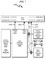
- A TempAssure equipped PARALLAX AC to DC converter. These signal lines are provided by the umbilical connection from the TempAssure unit to a modular jack or connection point (J1 in this exemplary embodiment).
- System connections for the RV (RVEES) as provided by terminals or other connection means. (J3 in this exemplary embodiment).
- A combination of these signal lines, and additional lines as necessary provided from terminals on an expansion module to monitor and control RVEES elements as required.
-
- All non-TempAssure converters either manufactured by PARALLAX or some other manufacturer will interface (and be provide power for) by connecting to the SYS+ (Positive) and SYS− (Negative) terminals on J3 (
FIG. 10 (1000)). This will power the user interface, as well as provide the voltage signal for the voltage meter portion of the interface. This voltage is considered to be the system voltage in most embodiments, and will be used to determine functions based on system voltage levels (i.e. high voltage alarm). - Automatic Transfer Switches and Energy Management Devices. These type of devices from any manufacturer currently must be hard wired from a sensing device or direct connection at the device or device cabling to the I/O lines of the UCSM or additionally the UCSM expansion module (such as in the power monitoring set up of an automatic transfer switch which is illustrated as requiring 12 I/O lines, the additional termination points would be made available as part of the expansion module). As PARALLAX (or other RVEES) products evolve, the present invention anticipates that they may include design-in functionality to devices allowing them to more directly integrate with the user interface panel.
- The interfacing techniques shown in the Transfer Switch Integration drawing (
FIG. 28 (2800),FIG. 29 (2900)) would be common for many high voltage or high current devices in the RVEES. - Low voltage or signal level inputs may be wired directly to I/O terminals on the USCM or USCM module. This would include most low power 12VDC devices or signals obtained from storage tank probes for example.
One skilled in the art will recognize that by providing the expansion module landing array and plug matrix the UCSM permits incorporation of additional sensing/control functions to the RVEES environment without major hardware modifications to the RVUI.
- All non-TempAssure converters either manufactured by PARALLAX or some other manufacturer will interface (and be provide power for) by connecting to the SYS+ (Positive) and SYS− (Negative) terminals on J3 (
-
- (1) determining if a cycle delay has elapsed, and if not, proceeding to step (1) (1601);
- (2) incrementing a counter (1602);
- (3) determining if the counter value is equal to a preset count parameter C2 (nominally 2), and if not, proceeding to step (5) (1603);
- (4) disconnecting the battery and proceeding to step (1) (1604);
- (5) determining if battery storage mode is enabled, and if not, proceeding to step (7) (1605);
- (6) determining if the counter value is equal to a preset count parameter C8 (nominally 8), and if so, proceeding to step (8), otherwise proceeding to step (4) (1606);
- (7) determining if the counter value is equal to a preset count parameter C6 (nominally 6), and if not, proceeding to step (12) (1607);
- (8) determining if the battery voltage is greater than a predetermined upper voltage VH (nominally 12.7V), and if so, proceeding to step (1) (1608);
- (9) determining if the battery voltage is greater than a predetermined lower voltage VL (nominally 12.5V), and if not, proceeding to step (11) (1609);
- (10) enabling battery boost charging (1610);
- (11) connecting the battery to the charger and proceeding to step (1) (1611);
- (12) determining if the counter value is equal to a preset count parameter C9 (nominally 9), and if not, proceeding to step (1) (1612); and
- (13) resetting the counter value to zero and proceeding to step (1) (1613).
One skilled in the art will recognize that these method steps may be augmented or rearranged without limiting the teachings of the present invention. This general method summary may be augmented by the various elements described herein to produce a wide variety of invention embodiments consistent with this overall design description.
-
- (1) determine if the battery charge converter and the load system are both active, and if not, proceeding to step (1) (1701);
- (2) continuously monitor the converter voltage and if the converter voltage falls below an upper threshold VH (13.0V nominal) and the battery voltage is greater than a lower threshold VL (12.3V nominal), then connect the battery to the battery charge converter regardless of any other state (1702);
- (3) wait a first time period T1 (nominally 0.5 hour) (1703);
- (4) disconnect the battery from the charge converter (1704);
- (5) wait a time period T2 (nominally 1.0 hour) (1705);
- (6) wait a time period T3 (nominally 0.25 hour) (1706);
- (7) measure the battery voltage (or conclude measurement in monitoring application) (1707);
- (8) determine if the measured battery voltage indicates a charge mode is necessary, and if so, proceeding to step (10) (1708);
- (9) connect the battery to the converter system and adjusting the converter voltage to the proper battery charging stage based on the measured battery voltage (1709); and
- (10) disconnecting the battery from the converter and proceed to step (6) (1710).
One skilled in the art will recognize that these method steps may be augmented or rearranged without limiting the teachings of the present invention. This general method summary may be augmented by the various elements described herein to produce a wide variety of invention embodiments consistent with this overall design description.
-
- (1) disconnecting the battery from the battery charging converter (2201);
- (2) measuring the no-load battery voltage (2202);
- (3) deciding on a battery charging method based on the measured no-load battery voltage (2203);
- (4) connecting the battery to the battery charging converter (2204);
- (5) activating the battery charge cycle (2205); and
- (6) waiting a selected battery charging interval and then proceeding to step (1) (2206).
One skilled in the art will recognize that these method steps may be augmented or rearranged without limiting the teachings of the present invention. This general method summary may be augmented by the various elements described herein to produce a wide variety of invention embodiments consistent with this overall design description.
-
- (1) continuously monitoring the utility power connection status (LINE1, LINE2, NEUTRAL, GROUND) (2301);
- (2) determining if good utility power is detected for approximately 90 s, and if not, proceeding to step (5) (2302);
- (3) activating the shore contactor (K1) (2303);
- (4) continuously monitoring the generator power connection status (LINE1, LINE2, NEUTRAL, GROUND) (2304);
- (5) determining if generator power is detected, and if not, proceeding to step (3) (2305);
- (6) determining if good generator power is detected for approximately 90 s, and if not, proceeding to step (5) (2306);
- (7) releasing the shore contactor (K1) (2307);
- (8) activating the generator contactor (K2) (2308);
- (9) determining if generator power is detected, and if so, proceeding to step (8) (2309); and
- (10) deactivating the generator contactor (K2) and proceeding to step (1) (2310).
One skilled in the art will recognize that these method steps may be augmented or rearranged without limiting the teachings of the present invention. This general method summary may be augmented by the various elements described herein to produce a wide variety of invention embodiments consistent with this overall design description.
-
- The ability to control the UCSM functionality remotely via a wireless mobile device.
- The ability to monitor UCSM functions as displayed on the CUID.
- The ability to provide user interface on the mobile device (4134) that may mimic the CUID display or some other user-selected interface.
- The ability to relay alarms relating to monitored UCSM functions to the mobile device (4134).
-
- (1) Scanning for a wireless remote access request (4501). This step may this step involves determining the presence of a compatible mobile device that is attempting to communicate with the UCSM.
- (2) Determining if a remote mobile device is attempting to login to the UCSM for access control, and if not, proceeding to step (1) (4502).
- (3) Validating access by the mobile RVDMA device to determine if it is properly authorized to access the UCSM (4503).
- (4) Determining if remote access is validated, and if so, proceeding to step (6) (4504).
- (5) Denying remote mobile access to the UCSM, posting an error message to the RVDMA, and proceeding to step (1) (4505).
- (6) Posting an access granted message to the RVDMA via the wireless connection (4506).
- (7) Determining if wireless communication is still active between the UCSM and the RVDMA, and if not, proceeding to step (1) (4607).
- (8) Gathering RVEES sensor information (4608).
- (9) Determining if a RVEES sensor alarm is detected, and if not, proceeding to step (12) (4609).
- (10) Sending an alarm message via the wireless link to the RVDMA (4610).
- (11) Clearing the RVDMA associated with the alarm condition (to prevent recurrent RVDMA alarms) and proceeding to step (8) (4611).
- (12) Determining if RVEES status information is initially unknown to the RVDMA or changed since the last RVDMA display update, and if not, proceeding to step (15) (4612).
- (13) Formatting status display information based on collected RVEES status information (4613).
- (14) Transmitting the formatted status display information to the RVDMA via the wireless link (4614).
- (15) Determining if a RVDMA keyboard/keypad input has been received, and if not, proceeding to step (7) (4715).
- (16) Mapping the RVDMA keyboard/keypad input to an equivalent RVEES control function (4716).
- (17) Determining if the mapped RVEES control function is available for execution or allowed to the user based on access control limitations configured within the RVWUI, and if so, proceeding to step (19) (4717).
- (18) Sending an error/warning message to the RVDMA via the wireless communication link (4718).
- (19) Determining if an alarm function command has been received, and if not, proceeding to step (21) (4719).
- (20) Setting/clearing the alarm threshold in the UCSM based on the RVDMA alarm message content and proceeding to step (7) (4720).
- (21) Setting the UCSM control function based on the RVDMA control message content and proceeding to step (7) (4721).
One skilled in the art will recognize that these method steps may be augmented or rearranged without limiting the teachings of the present invention. This general method summary may be augmented by the various elements described herein to produce a wide variety of invention embodiments consistent with this overall design description.
-
- (1) Presenting a user configuration screen to the remote mobile user and permitting the user to enter presentation interface parameters (4801). This step may include selection of a given user interface from among a variety of possible user interfaces, and may involve mapping a variety of different controls associated with the RVEES to a preselected set of modal dialog screens that are presented to the user for configuration/monitoring of RVEES components. This information may be stored in a user interface setup dataset (4811). Thus, there may exist differences between the form and function of the RVEES displays/controls associated with the CUID and the user interface selected for use by the mobile user in this context.
- (2) Presenting the mobile user with an access screen and entering RVWUI access information (4802).
- (3) Establishing or maintaining wireless communication between the mobile RVDMA and the RVWUI host system (4803).
- (4) Determining if remote access is granted, and if not, proceeding to step (2) (4804).
- (5) Determining if communication between the RVWUI and the RVDMA is active (or data is received) and if not, proceeding to step (3) (4805).
- (6) Determining if a display update has been received, and if not, proceeding to step (8) (4806).
- (7) Presenting updated display information to the mobile user interface (4807) using data provided by the RVWUI and the display formatting defined by the RVDMA UI setup parameters (4811) and proceeding to step (5).
- (8) Determining if a mobile user keyboard/keypad entry has been detected, and if not, proceeding to step (5) (4808).
- (9) Decoding the mobile keyboard/keypad entry (4809) as defined by the RVDMA UI parameters (4811).
- (10) Wirelessly transmitting the decode keyboard/keypad entry to the RVWUI (4810) and proceeding to step (5).
One skilled in the art will recognize that these method steps may be augmented or rearranged without limiting the teachings of the present invention. This general method summary may be augmented by the various elements described herein to produce a wide variety of invention embodiments consistent with this overall design description.
-
- 120VAC rated at 30 amps.
- 120/240VAC rated at 50 amps (typically this is configured as two 120VAC lines capable of 50 amps each).
Monitoring the voltage, amperage, and load balance, polarity, and open conductors on 120/240 volt systems is desirable to prevent accidental breaker tripping, or possible equipment damage due to improper input voltage.
Generator Supply
-
- Presence of source AC voltage at shoreline input.
- Presence of source AC voltage at generator input.
- Verification of output AC voltage at output to RV AC electrical system.
- Subsystems such as the PARALLAX POWER SUPPLY ATS501 Transfer Switch contain logic that indicates when there is a switching fault. This feature (and others present in various other power supply subsystems) may be monitored in some preferred invention embodiments.
- Forcing the switch to return to shore connection even though the generator is still running.
This list is only exemplary of the types of monitoring and control that are possible using the present invention.
Nominal 12VDC (24VDC) Electrical System
-
- Different battery technologies ideally have different charging parameters. The ability to select the type of battery technology could modify the operation of a power supply converter subsystem (such as the PARALLAX POWER SUPPLY CONVERTER SYSTEM) to provide more suitable charging for the selected battery type.
- Battery voltage monitoring.
- Battery drain or charge rate (current) monitoring.
- Battery temperature monitoring.
This list is only exemplary of the types of monitoring and control that are possible using the present invention.
RV Converter
-
- input voltage
- input current;
- output voltage;
- output current;
- the ability to shut off the converter's output; and/or
- control of special converter functions.
Examples of special converter functions may include: - In PARALLAX CONVERTERS, turning the high charge rate function on and off, incorporating the monitoring/control functions as listed above, and/or incorporating monitoring/control functions in addition to those listed above.
- In other converter systems having special control features which may be controlled remotely through the monitoring/control functions of the present invention. These monitoring and control parameters may be performed by the use of sensing wires run to the output of the converter in addition to a current shunt being installed in the DC output of the converter system and sensing wires being connected to the shunts.
Current Shunts
-
- Monitoring of the status open or closed.
- Control of the status open or closed.
Storage Tanks
-
- Provide for advanced battery charging techniques within the context of RVEES subsystems.
- Offer a RV manufacturer a customized monitoring/control solution based on the specific needs of their application. This solution would allow for the elimination of many if not all of the individual switches and displays currently being used, thus reducing mounting space and installation time significantly.
- As an individual aftermarket retrofit application, the present invention incorporating the Standard Alarm Module described herein would produce a general purpose configuration, allowing the connection of any converter system readily available as well as the ability to control any currently installed battery disconnect relay. In a situation such as this the RVUI unit could easily be upgraded in the future by incorporating TrueSense a charging module and adding a TempAssure converter system.
- While it is not practical to illustrate every conceivable possibility of the present invention, key functions and features of the invention have been illustrated herein. The ability for any element desirable in the RVEES to be monitored either as an on/off condition or as a signal level of some sort (typically voltage or current) within the context of a universal monitoring/control system is extremely powerful given the current diversity in monitoring/control within RVEES subsystems currently on the market. Additionally, based on the outcome of the monitored signal(s) some action be taken whether it is in the form of an indicator, alarm, the adjustment of some other device with in the RVEES, or combination of these responses. The control of these signals and responses can be performed in a variety of means, the simplest being primarily from the use of comparator circuits that will either turn on or off when a certain threshold or set point is met, along with logic gates to perform math when multiple signals may be involved, these methods have been illustrated in a manner of ways. Other methods of signal monitoring could be by the use of mixed signal technology such as analog-to-digital converters, to ultimately, software programmed microcontrollers in the more advanced invention design embodiments. The manner and technology that is employed will depend largely on the technical and financial requirements of the client application.
- The incorporation of a “True Sense” battery charging module and system (as described herein), with the system consisting of a TempAssure converter, controller (in this case the user interface described herein) and battery disconnect relay provides a substantially improved control and optimization of battery charging within an RV context that is currently not available in the prior art.
-
- (a) universal control/sensor motherboard (UCSM);
- (b) customizable user interface daughterboard (CUID); and
- (c) custom indicia bezel/panel (CIBP);
- wherein
- the UCSM is configured to accept electrical inputs from and distribute electrical outputs to electrical controls and environmental sensors within a plethora of recreational vehicle electrical/environmental subsystems (RVEES);
- the UCSM is configured to electrically communicate with the CUID to send status information regarding the RVEES to the CUID;
- the UCSM is configured to electrically communicate with the CUID to accept command inputs from the CUID for configuration of the RVEES;
- the CUID comprises a status display that presents the status information to a user;
- the CUID comprises a control input configured to provide the command inputs;
- the CIBP is configured to cover the PCB of the CUID;
- the CIBP is configured to present custom legends and indicia proximal to the status display; and
- the CIBP is configured to present custom legends and indicia proximal to the control input.
-
- (a) universal control/sensor motherboard (UCSM);
- (b) customizable user interface daughterboard (CUID); and
- (c) custom indicia bezel/panel (CIBP);
- wherein
- the UCSM is configured to accept electrical inputs from and distribute electrical outputs to electrical controls and environmental sensors within a plethora of recreational vehicle electrical/environmental subsystems (RVEES);
- the UCSM is configured to electrically communicate with the CUID to send status information regarding the RVEES to the CUID;
- the UCSM is configured to electrically communicate with the CUID to accept command inputs from the CUID for configuration of the RVEES;
- the CUID comprises a status display that presents the status information to a user;
- the CUID comprises a control input configured to provide the command inputs;
- the CIBP is configured to cover the PCB of the CUID;
- the CIBP is configured to present custom legends and indicia proximal to the status display; and
- the CIBP is configured to present custom legends and indicia proximal to the control input;
- the UCSM comprises a wireless communication interface (WCI);
- the WCI is electrically connected to and communicates with the UCSM;
- the WCI is configured to interact with a mobile communication device (MCD) via wireless communication;
- the MCD executes application software read from a computer readable medium;
- the application software is configured to present a graphical user interface (GUI) on the MCD;
- the GUI is configured to permit a user to receive RVEES status from the UCSM; and
- the GUI is configured to permit a user to direct RVEES operation of the UCSM.
-
- (a) universal control/sensor motherboard (UCSM);
- (b) customizable user interface daughterboard (CUID); and
- (c) custom indicia bezel/panel (CIBP);
- wherein
- the UCSM is configured to accept electrical inputs from and distribute electrical outputs to electrical controls and environmental sensors within a plethora of recreational vehicle electrical/environmental subsystems (RVEES);
- the UCSM is configured to electrically communicate with the CUID to send status information regarding the RVEES to the CUID;
- the UCSM is configured to electrically communicate with the CUID to accept command inputs from the CUID for configuration of the RVEES;
- the CUID comprises a status display that presents the status information to a user;
- the CUID comprises a control input configured to provide the command inputs;
- the CIBP is configured to cover the PCB of the CUID;
- the CIBP is configured to present custom legends and indicia proximal to the status display; and
- the CIBP is configured to present custom legends and indicia proximal to the control input;
- wherein the method comprises the steps of:
- (1) electrically interconnecting the electrical inputs of the UCSM to monitoring nodes within the electrical system of the RVEES;
- (2) electrically interconnecting the electrical outputs of the UCSM to control nodes within the electrical system of the RVEES;
- (3) configuring the CUID to provide a customized user hardware interface to the UCSM consistent with the interconnections in step (1) and step (2);
- (4) configuring the CIBP with legends and indicia to conform to the CUID customized user hardware interface;
- (5) relaying status information from the RVEES to the UCSM for presentation on the CUID status display as presented by the CIBP to a user; and
- (6) relaying control inputs from the CUID to the UCSM for transmission to the RVEES to control RVEES functions defined by the user interface presented on the CIBP.
One skilled in the art will recognize that these method steps may be augmented or rearranged without limiting the teachings of the present invention. This general method summary may be augmented by the various elements described herein to produce a wide variety of invention embodiments consistent with this overall design description.
-
- (1) determining if a cycle delay has elapsed, and if not, proceeding to step (1);
- (2) incrementing a counter value;
- (3) determining if the counter value is equal to a preset count parameter C2, and if not, proceeding to step (5);
- (4) disconnecting the battery from a battery charger and proceeding to step (1);
- (5) determining if battery storage mode is enabled, and if not, proceeding to step (7);
- (6) determining if the counter value is equal to a preset count parameter C8, and if so, proceeding to step (8), otherwise proceeding to step (4);
- (7) determining if the counter value is equal to a preset count parameter C6, and if not, proceeding to step (12);
- (8) determining if the battery voltage is greater than a predetermined upper voltage VH, and if so, proceeding to step (1);
- (9) determining if the battery voltage is greater than a predetermined lower voltage VL, and if not, proceeding to step (11);
- (10) enabling battery boost charging;
- (11) connecting the battery to the charger and proceeding to step (1);
- (12) determining if the counter value is equal to a preset count parameter C9, and if not, proceeding to step (1); and
- (13) resetting the counter value to zero and proceeding to step (1).
One skilled in the art will recognize that these method steps may be augmented or rearranged without limiting the teachings of the present invention. This general method summary may be augmented by the various elements described herein to produce a wide variety of invention embodiments consistent with this overall design description.
-
- (1) determining if a battery charge converter and associated load system are both active, and if not, proceed to step (1);
- (2) continuously monitoring the converter voltage and if the converter voltage falls below an upper threshold VH and the battery voltage is greater than a lower threshold VL, then connecting the battery to the battery charge converter regardless of any other state;
- (3) waiting a first time period T1;
- (4) disconnecting the battery from the charge converter;
- (5) waiting a time period T2;
- (6) waiting a time period T3;
- (7) measuring the battery voltage;
- (8) determining if the measured battery voltage indicates a charge mode is necessary, and if so, proceeding to step (10);
- (9) connecting the battery to the converter system and adjusting the converter voltage to the proper battery charging stage based on the measured battery voltage; and
- (10) disconnecting the battery from the converter and proceed to step (6).
One skilled in the art will recognize that these method steps may be augmented or rearranged without limiting the teachings of the present invention. This general method summary may be augmented by the various elements described herein to produce a wide variety of invention embodiments consistent with this overall design description.
-
- (1) disconnecting the battery from a battery charging converter;
- (2) measuring the no-load battery voltage;
- (3) deciding on a battery charging method based on the measured no-load battery voltage;
- (4) connecting the battery to the battery charging converter;
- (5) activating a battery charge cycle for the battery; and
- (6) waiting a selected battery charging interval and then proceeding to step (1).
One skilled in the art will recognize that these method steps may be augmented or rearranged without limiting the teachings of the present invention. This general method summary may be augmented by the various elements described herein to produce a wide variety of invention embodiments consistent with this overall design description.
-
- (1) continuously monitoring the utility power connection status (LINE1, LINE2, NEUTRAL, GROUND);
- (2) determining if good utility power is detected for approximately 90 s, and if not, proceeding to step (5);
- (3) activating a shore contactor (K1);
- (4) continuously monitoring the generator power connection status (LINE1, LINE2, NEUTRAL, GROUND);
- (5) determining if generator power is detected, and if not, proceeding to step (3);
- (6) determining if good generator power is detected for approximately 90 s, and if not, proceeding to step (5);
- (7) releasing the shore contactor (K1);
- (8) activating a generator contactor (K2);
- (9) determining if generator power is detected, and if so, proceeding to step (8); and
- (10) deactivating the generator contactor (K2) and proceeding to step (1).
One skilled in the art will recognize that these method steps may be augmented or rearranged without limiting the teachings of the present invention. This general method summary may be augmented by the various elements described herein to produce a wide variety of invention embodiments consistent with this overall design description.
-
- An embodiment wherein the RVEES is selected from a group consisting of: battery temperature, battery voltage, overall system voltage, battery disconnect relay, vent fan, solar panel, cabin temperature, temperature alarm, power converter module, temperature sensitive power converter, PARALLAX POWER SUPPLY, load management controller, AC distribution controller, transfer switch, AC/generator input, storage tank sensor, pump motor, 12V electrical load, and 24V electrical load.
- An embodiment wherein the status display comprises an indicator selected from a group consisting of: battery voltage bar graph; battery low voltage alarm display; battery high voltage alarm display; battery voltage digital display; battery temperature bar graph; battery low temperature alarm display; battery high temperature alarm display; battery voltage digital display; storage tank level bar graph; storage tank low level alarm display; storage tank high level alarm display; storage tank level digital display.
- An embodiment wherein the status display and the control input comprise a touch screen display/control.
- An embodiment wherein the CUID comprises an alarm indicator selected from a group consisting of: audible alarm; audible alarm that is enabled in response to activation of the status display.
- An embodiment wherein the UCSM comprises a printed circuit board (PCB) further comprising an Expansion Module Landing Array (EMLA).
- An embodiment wherein the UCSM comprises a wireless communication interface (WCI) wherein the WCI is configured to interact with a mobile communication device (MCD) via wireless communication; the MCD executes application software read from a computer readable medium; the application software is configured to present a graphical user interface (GUI) on the MCD; the GUI is configured to permit a user to receive RVEES status from the UCSM; and the GUI is configured to permit a user to direct RVEES operation of the UCSM.
- An embodiment wherein the WCI comprises a wireless interface selected from a group consisting of: BLUETOOTH® wireless communication interface; and WiFi wireless communication interface.
- An embodiment wherein the MCD comprises a device selected from a group consisting of: laptop computer; tablet computer; cellphone; mobile phone; and smartphone.
- An embodiment wherein the application software is configured to interrogate the UCSM and reconfigure the GUI based on the configuration status of the CUID.
- An embodiment wherein the count parameter C2 has a value of approximately 2.
- An embodiment wherein the count parameter C6 has a value of approximately 6.
- An embodiment wherein the count parameter C8 has a value of approximately 8.
- An embodiment wherein the count parameter C9 has a value of approximately 9.
- An embodiment wherein the voltage VL has a value of approximately 12.5V.
- An embodiment wherein the voltage VH has a value of approximately 12.7V.
- An embodiment wherein the lower threshold has a value of approximately 12.3V.
- An embodiment wherein the upper threshold has a value of approximately 13.0V.
- An embodiment wherein the time period T1 has a value of approximately 0.5 hour.
- An embodiment wherein the time period T2 has a value of approximately 1.5 hour.
- An embodiment wherein the time period T3 has a value of approximately 0.25 hour.
Claims (20)
Priority Applications (2)
| Application Number | Priority Date | Filing Date | Title |
|---|---|---|---|
| US13/794,088 US8767379B2 (en) | 2013-02-11 | 2013-03-11 | Recreational vehicle user interface system and method |
| US14/285,091 US20140253050A1 (en) | 2013-02-11 | 2014-05-22 | Recreational Vehicle User Interface System and Method |
Applications Claiming Priority (2)
| Application Number | Priority Date | Filing Date | Title |
|---|---|---|---|
| US201361763230P | 2013-02-11 | 2013-02-11 | |
| US13/794,088 US8767379B2 (en) | 2013-02-11 | 2013-03-11 | Recreational vehicle user interface system and method |
Related Child Applications (1)
| Application Number | Title | Priority Date | Filing Date |
|---|---|---|---|
| US14/285,091 Division US20140253050A1 (en) | 2013-02-11 | 2014-05-22 | Recreational Vehicle User Interface System and Method |
Publications (2)
| Publication Number | Publication Date |
|---|---|
| US20130197748A1 US20130197748A1 (en) | 2013-08-01 |
| US8767379B2 true US8767379B2 (en) | 2014-07-01 |
Family
ID=48870969
Family Applications (2)
| Application Number | Title | Priority Date | Filing Date |
|---|---|---|---|
| US13/794,088 Expired - Fee Related US8767379B2 (en) | 2013-02-11 | 2013-03-11 | Recreational vehicle user interface system and method |
| US14/285,091 Abandoned US20140253050A1 (en) | 2013-02-11 | 2014-05-22 | Recreational Vehicle User Interface System and Method |
Family Applications After (1)
| Application Number | Title | Priority Date | Filing Date |
|---|---|---|---|
| US14/285,091 Abandoned US20140253050A1 (en) | 2013-02-11 | 2014-05-22 | Recreational Vehicle User Interface System and Method |
Country Status (1)
| Country | Link |
|---|---|
| US (2) | US8767379B2 (en) |
Cited By (29)
| Publication number | Priority date | Publication date | Assignee | Title |
|---|---|---|---|---|
| US9762012B1 (en) | 2016-06-11 | 2017-09-12 | Gus Roy LeGros, Jr. | Vehicular electrical adapter cord having a standard 110/120 volt residential receptacle |
| US9896106B1 (en) | 2016-10-24 | 2018-02-20 | Toyota Motor Engineering & Manufacturing North America, Inc. | Coasting distance determination for coasting assistance system |
| US9898928B1 (en) | 2016-10-25 | 2018-02-20 | Toyota Motor Engineering & Manufacturing North America, Inc. | Coasting guidance timing and learning based on approach lane |
| US9908122B2 (en) | 2014-07-24 | 2018-03-06 | Thetford Corporation | Waste fluid holding tank drain system and method |
| CN108099818A (en) * | 2016-11-25 | 2018-06-01 | 比亚迪股份有限公司 | The self-learning method and self learning system and vehicle of vehicle configuration information |
| US10017172B2 (en) | 2016-11-02 | 2018-07-10 | Toyota Motor Engineering & Manufacturing North America, Inc. | System and method for pulsing display to provide coasting coach guidance |
| US10189453B2 (en) | 2016-10-05 | 2019-01-29 | Toyota Motor Engineering & Manufacturing North America, Inc. | Coasting guidance timing and drive force adjustment |
| WO2019140483A1 (en) * | 2018-01-17 | 2019-07-25 | Redarc Technologies Pty Ltd | A power distribution system and method |
| WO2019143756A1 (en) * | 2018-01-19 | 2019-07-25 | Thor Tech, Inc. | Integrated body control and weight sensing system |
| US20210070135A1 (en) * | 2019-09-09 | 2021-03-11 | Thermo King Corporation | System and method for managing power and efficiently sourcing a variable voltage for a transport climate control system |
| US10985511B2 (en) | 2019-09-09 | 2021-04-20 | Thermo King Corporation | Optimized power cord for transferring power to a transport climate control system |
| US10988026B2 (en) | 2018-09-26 | 2021-04-27 | Ford Global Technologies, Llc | Vehicle electrical load shed |
| US11034213B2 (en) | 2018-09-29 | 2021-06-15 | Thermo King Corporation | Methods and systems for monitoring and displaying energy use and energy cost of a transport vehicle climate control system or a fleet of transport vehicle climate control systems |
| US11192451B2 (en) | 2018-09-19 | 2021-12-07 | Thermo King Corporation | Methods and systems for energy management of a transport climate control system |
| US11203262B2 (en) | 2019-09-09 | 2021-12-21 | Thermo King Corporation | Transport climate control system with an accessory power distribution unit for managing transport climate control loads |
| US11214118B2 (en) | 2019-09-09 | 2022-01-04 | Thermo King Corporation | Demand-side power distribution management for a plurality of transport climate control systems |
| US11260723B2 (en) | 2018-09-19 | 2022-03-01 | Thermo King Corporation | Methods and systems for power and load management of a transport climate control system |
| USD947699S1 (en) | 2019-03-11 | 2022-04-05 | Dometic Sweden Ab | Controller |
| US11332084B2 (en) * | 2019-04-02 | 2022-05-17 | Psa Automobiles Sa | Method for adapting a wiring harness for a motor-driven land vehicle |
| US11376922B2 (en) | 2019-09-09 | 2022-07-05 | Thermo King Corporation | Transport climate control system with a self-configuring matrix power converter |
| USD961611S1 (en) | 2020-06-30 | 2022-08-23 | Thor Tech, Inc. | Electronic device with graphical user interface |
| US11420495B2 (en) | 2019-09-09 | 2022-08-23 | Thermo King Corporation | Interface system for connecting a vehicle and a transport climate control system |
| US11440556B2 (en) | 2019-12-12 | 2022-09-13 | Thor Tech, Inc. | Trailed vehicles, mobile devices, and weight sensing system user interfaces comprised therein |
| US11458802B2 (en) | 2019-09-09 | 2022-10-04 | Thermo King Corporation | Optimized power management for a transport climate control energy source |
| US11489431B2 (en) | 2019-12-30 | 2022-11-01 | Thermo King Corporation | Transport climate control system power architecture |
| US11626734B2 (en) | 2022-01-05 | 2023-04-11 | Paul Spivak | Energy management system for a recreational vehicle |
| US11695275B2 (en) | 2019-09-09 | 2023-07-04 | Thermo King Llc | Prioritized power delivery for facilitating transport climate control |
| US11691475B2 (en) | 2021-04-30 | 2023-07-04 | Haier Us Appliance Solutions, Inc. | Universal control for recreational vehicle air conditioner |
| US11794551B2 (en) | 2019-09-09 | 2023-10-24 | Thermo King Llc | Optimized power distribution to transport climate control systems amongst one or more electric supply equipment stations |
Families Citing this family (28)
| Publication number | Priority date | Publication date | Assignee | Title |
|---|---|---|---|---|
| DE102013006254A1 (en) * | 2013-04-11 | 2014-10-16 | Audi Ag | Voltage release of a high voltage vehicle |
| WO2015080683A1 (en) * | 2013-11-26 | 2015-06-04 | Otokar Otomotiv Ve Savunma Sanayi Anonim Sirketi | Battery charge warning system |
| CN104198950B (en) * | 2014-09-27 | 2017-07-11 | 奇瑞汽车股份有限公司 | A kind of method for real-time monitoring of battery condition |
| US20160233707A1 (en) * | 2015-02-06 | 2016-08-11 | Michael Kidakarn | Power Adapter with Charging Data Display |
| CN104808621B (en) * | 2015-03-11 | 2018-05-08 | 中国科学院微电子研究所 | A kind of wireless intelligent monitoring system and method for kitchen truck |
| US9701200B2 (en) * | 2015-07-31 | 2017-07-11 | Ford Global Technologies, Llc | Selectable cabin conditioning during electrified vehicle charging |
| CN105140985B (en) * | 2015-08-05 | 2017-08-25 | 青岛海信移动通信技术股份有限公司 | Mobile terminal, can directly charge source adapter and charging method |
| CN104993565B (en) | 2015-08-05 | 2017-12-05 | 青岛海信移动通信技术股份有限公司 | Can directly be charged source adapter |
| CN105098900B (en) | 2015-08-05 | 2018-05-29 | 青岛海信移动通信技术股份有限公司 | Mobile terminal, can directly charge source adapter and charging method |
| GB2537274B (en) * | 2015-10-16 | 2018-02-14 | Ford Global Tech Llc | A vehicle electrical system |
| US9842448B1 (en) * | 2016-09-23 | 2017-12-12 | Honda Motor Co., Ltd. | Real-time vehicle feature customization at point of access |
| CN106740595A (en) * | 2016-12-08 | 2017-05-31 | 甄华伟 | Automobile storage battery pile crown end power alarm self-help apparatus |
| CA2988160A1 (en) | 2016-12-09 | 2018-06-09 | Southwire Company, Llc | Open neutral detector |
| CN109510965A (en) * | 2017-11-09 | 2019-03-22 | 蔚来汽车有限公司 | Electricity changing monitoring system |
| GB2572941A (en) * | 2018-02-28 | 2019-10-23 | Christopher Rees John | Caravan monitor |
| US10882411B2 (en) * | 2018-01-18 | 2021-01-05 | Ford Global Technologies, Llc | Smart charging schedules for battery systems and associated methods for electrified vehicles |
| CN108045333A (en) * | 2018-01-18 | 2018-05-18 | 智慧式控股有限公司 | A kind of vehicle comprehensive safety monitor control system of integrated form |
| US20210273447A1 (en) * | 2018-03-09 | 2021-09-02 | Hughes Autoformers LLC | Recreational vehicle power monitoring and reporting device and method |
| US11128934B2 (en) * | 2018-03-09 | 2021-09-21 | Hughes Autoformers, Llc | Recreational vehicle power monitor and reporting device and method |
| DE102018114906A1 (en) * | 2018-06-21 | 2019-12-24 | Eberspächer Climate Control Systems GmbH & Co. KG | Vehicle auxiliary equipment control system |
| CN108928213B (en) * | 2018-07-17 | 2022-04-19 | 深圳市汇川技术股份有限公司 | Parameter configuration method of control panel, control panel and controlled equipment |
| CN109933025A (en) * | 2018-12-29 | 2019-06-25 | 丰疆智慧农业股份有限公司 | Intelligent agricultural machinery electric quantity managing method and power management system |
| US10414357B1 (en) * | 2019-06-03 | 2019-09-17 | Wild Energy, Inc. | System to selectively provide power to recreational vehicles with a SaaS application accessed via mobile devices |
| CN110374852B (en) * | 2019-07-25 | 2020-11-24 | 中车青岛四方车辆研究所有限公司 | Frequency calculation method for variable-frequency air conditioner compressor |
| US20210155142A1 (en) * | 2019-11-26 | 2021-05-27 | Christopher Greer | Smart recreational vehicle power center |
| WO2022034358A1 (en) * | 2020-08-12 | 2022-02-17 | Provazek Michal | Hybrid modular system for complex surveillance, control and safety of mobile housing objects, in particular caravans, recreational vehicles and vessels |
| CN112506150A (en) * | 2020-12-01 | 2021-03-16 | 深圳铭薪房车科技有限公司 | Car as a house intelligence control system |
| US11766949B2 (en) * | 2021-06-01 | 2023-09-26 | Ford Global Technologies, Llc | Charging notification strategies for vehicle-to-recreational vehicle energy transfer systems |
Citations (8)
| Publication number | Priority date | Publication date | Assignee | Title |
|---|---|---|---|---|
| US6107696A (en) * | 1994-12-19 | 2000-08-22 | Robert Bosch Gmbh | Circuitry for function modules which can be fitted in a motor vehicle |
| US6249425B1 (en) * | 1998-07-21 | 2001-06-19 | Harness System Technologies Research, Ltd. | Wiring structure for instrument panel of vehicle |
| US6469404B1 (en) * | 1997-11-14 | 2002-10-22 | Iws International Inc. | Intelligent control system for current distribution in a vehicle |
| US6879895B2 (en) * | 2002-04-23 | 2005-04-12 | Rick W. Capps | Method and handling apparatus for a vehicular electrical system |
| US6965818B2 (en) * | 2001-11-28 | 2005-11-15 | Onan Corporation | Mobile energy management system |
| US7245109B2 (en) | 2005-11-30 | 2007-07-17 | Parailax Power Supply, Llc | Temperature sensitive power converter |
| US7592713B2 (en) * | 2005-02-25 | 2009-09-22 | Marathon Coach, Inc. | Electrical system for controlling coach resources |
| US8199507B2 (en) * | 2008-12-19 | 2012-06-12 | Openpeak Inc. | Telephony and digital media services device |
Family Cites Families (7)
| Publication number | Priority date | Publication date | Assignee | Title |
|---|---|---|---|---|
| US4152635A (en) * | 1977-07-14 | 1979-05-01 | Research Development Systems, Inc. | Battery charger |
| US5998968A (en) * | 1997-01-07 | 1999-12-07 | Ion Control Solutions, Llc | Method and apparatus for rapidly charging and reconditioning a battery |
| US6111389A (en) * | 1998-06-18 | 2000-08-29 | Lucent Technologies Inc. | Rapidly charging a battery without overcharging |
| JP3929264B2 (en) * | 2001-07-30 | 2007-06-13 | 富士通株式会社 | Secondary battery charging device and method thereof |
| US6867568B1 (en) * | 2001-08-13 | 2005-03-15 | John Olson | Battery finish charge device |
| US20110082621A1 (en) * | 2009-10-02 | 2011-04-07 | Eric Berkobin | Method and system for predicting battery life based on vehicle battery, usage, and environmental data |
| US8310205B1 (en) * | 2011-03-21 | 2012-11-13 | Google Inc. | Managed battery charging |
-
2013
- 2013-03-11 US US13/794,088 patent/US8767379B2/en not_active Expired - Fee Related
-
2014
- 2014-05-22 US US14/285,091 patent/US20140253050A1/en not_active Abandoned
Patent Citations (8)
| Publication number | Priority date | Publication date | Assignee | Title |
|---|---|---|---|---|
| US6107696A (en) * | 1994-12-19 | 2000-08-22 | Robert Bosch Gmbh | Circuitry for function modules which can be fitted in a motor vehicle |
| US6469404B1 (en) * | 1997-11-14 | 2002-10-22 | Iws International Inc. | Intelligent control system for current distribution in a vehicle |
| US6249425B1 (en) * | 1998-07-21 | 2001-06-19 | Harness System Technologies Research, Ltd. | Wiring structure for instrument panel of vehicle |
| US6965818B2 (en) * | 2001-11-28 | 2005-11-15 | Onan Corporation | Mobile energy management system |
| US6879895B2 (en) * | 2002-04-23 | 2005-04-12 | Rick W. Capps | Method and handling apparatus for a vehicular electrical system |
| US7592713B2 (en) * | 2005-02-25 | 2009-09-22 | Marathon Coach, Inc. | Electrical system for controlling coach resources |
| US7245109B2 (en) | 2005-11-30 | 2007-07-17 | Parailax Power Supply, Llc | Temperature sensitive power converter |
| US8199507B2 (en) * | 2008-12-19 | 2012-06-12 | Openpeak Inc. | Telephony and digital media services device |
Non-Patent Citations (1)
| Title |
|---|
| Power Control System Model 100 Brochure; Precision Circuits, Inc., Lisle, IL 60532; [Date Unknown]; 2 pp. |
Cited By (36)
| Publication number | Priority date | Publication date | Assignee | Title |
|---|---|---|---|---|
| US9908122B2 (en) | 2014-07-24 | 2018-03-06 | Thetford Corporation | Waste fluid holding tank drain system and method |
| US9762012B1 (en) | 2016-06-11 | 2017-09-12 | Gus Roy LeGros, Jr. | Vehicular electrical adapter cord having a standard 110/120 volt residential receptacle |
| US10189453B2 (en) | 2016-10-05 | 2019-01-29 | Toyota Motor Engineering & Manufacturing North America, Inc. | Coasting guidance timing and drive force adjustment |
| US9896106B1 (en) | 2016-10-24 | 2018-02-20 | Toyota Motor Engineering & Manufacturing North America, Inc. | Coasting distance determination for coasting assistance system |
| US9898928B1 (en) | 2016-10-25 | 2018-02-20 | Toyota Motor Engineering & Manufacturing North America, Inc. | Coasting guidance timing and learning based on approach lane |
| US10017172B2 (en) | 2016-11-02 | 2018-07-10 | Toyota Motor Engineering & Manufacturing North America, Inc. | System and method for pulsing display to provide coasting coach guidance |
| CN108099818A (en) * | 2016-11-25 | 2018-06-01 | 比亚迪股份有限公司 | The self-learning method and self learning system and vehicle of vehicle configuration information |
| WO2019140483A1 (en) * | 2018-01-17 | 2019-07-25 | Redarc Technologies Pty Ltd | A power distribution system and method |
| WO2019143756A1 (en) * | 2018-01-19 | 2019-07-25 | Thor Tech, Inc. | Integrated body control and weight sensing system |
| US10486711B2 (en) | 2018-01-19 | 2019-11-26 | Thor Tech, Inc. | Integrated body control and weight sensing system |
| US11260723B2 (en) | 2018-09-19 | 2022-03-01 | Thermo King Corporation | Methods and systems for power and load management of a transport climate control system |
| US11192451B2 (en) | 2018-09-19 | 2021-12-07 | Thermo King Corporation | Methods and systems for energy management of a transport climate control system |
| US10988026B2 (en) | 2018-09-26 | 2021-04-27 | Ford Global Technologies, Llc | Vehicle electrical load shed |
| US11034213B2 (en) | 2018-09-29 | 2021-06-15 | Thermo King Corporation | Methods and systems for monitoring and displaying energy use and energy cost of a transport vehicle climate control system or a fleet of transport vehicle climate control systems |
| USD947699S1 (en) | 2019-03-11 | 2022-04-05 | Dometic Sweden Ab | Controller |
| USD1013546S1 (en) | 2019-03-11 | 2024-02-06 | Dometic Sweden Ab | Controller |
| US11332084B2 (en) * | 2019-04-02 | 2022-05-17 | Psa Automobiles Sa | Method for adapting a wiring harness for a motor-driven land vehicle |
| US11420495B2 (en) | 2019-09-09 | 2022-08-23 | Thermo King Corporation | Interface system for connecting a vehicle and a transport climate control system |
| US11135894B2 (en) * | 2019-09-09 | 2021-10-05 | Thermo King Corporation | System and method for managing power and efficiently sourcing a variable voltage for a transport climate control system |
| US11214118B2 (en) | 2019-09-09 | 2022-01-04 | Thermo King Corporation | Demand-side power distribution management for a plurality of transport climate control systems |
| US11203262B2 (en) | 2019-09-09 | 2021-12-21 | Thermo King Corporation | Transport climate control system with an accessory power distribution unit for managing transport climate control loads |
| US11376922B2 (en) | 2019-09-09 | 2022-07-05 | Thermo King Corporation | Transport climate control system with a self-configuring matrix power converter |
| US20210070135A1 (en) * | 2019-09-09 | 2021-03-11 | Thermo King Corporation | System and method for managing power and efficiently sourcing a variable voltage for a transport climate control system |
| US10985511B2 (en) | 2019-09-09 | 2021-04-20 | Thermo King Corporation | Optimized power cord for transferring power to a transport climate control system |
| US11712943B2 (en) | 2019-09-09 | 2023-08-01 | Thermo King Llc | System and method for managing power and efficiently sourcing a variable voltage for a transport climate control system |
| US11458802B2 (en) | 2019-09-09 | 2022-10-04 | Thermo King Corporation | Optimized power management for a transport climate control energy source |
| US11827106B2 (en) | 2019-09-09 | 2023-11-28 | Thermo King Llc | Transport climate control system with an accessory power distribution unit for managing transport climate control loads |
| US11794551B2 (en) | 2019-09-09 | 2023-10-24 | Thermo King Llc | Optimized power distribution to transport climate control systems amongst one or more electric supply equipment stations |
| US11695275B2 (en) | 2019-09-09 | 2023-07-04 | Thermo King Llc | Prioritized power delivery for facilitating transport climate control |
| US11440556B2 (en) | 2019-12-12 | 2022-09-13 | Thor Tech, Inc. | Trailed vehicles, mobile devices, and weight sensing system user interfaces comprised therein |
| US11843303B2 (en) | 2019-12-30 | 2023-12-12 | Thermo King Llc | Transport climate control system power architecture |
| US11489431B2 (en) | 2019-12-30 | 2022-11-01 | Thermo King Corporation | Transport climate control system power architecture |
| USD961611S1 (en) | 2020-06-30 | 2022-08-23 | Thor Tech, Inc. | Electronic device with graphical user interface |
| USD973713S1 (en) | 2020-06-30 | 2022-12-27 | Thor Tech, Inc. | Electronic device with graphical user interface |
| US11691475B2 (en) | 2021-04-30 | 2023-07-04 | Haier Us Appliance Solutions, Inc. | Universal control for recreational vehicle air conditioner |
| US11626734B2 (en) | 2022-01-05 | 2023-04-11 | Paul Spivak | Energy management system for a recreational vehicle |
Also Published As
| Publication number | Publication date |
|---|---|
| US20140253050A1 (en) | 2014-09-11 |
| US20130197748A1 (en) | 2013-08-01 |
Similar Documents
| Publication | Publication Date | Title |
|---|---|---|
| US8767379B2 (en) | Recreational vehicle user interface system and method | |
| US10263436B2 (en) | Electrical energy storage unit and control system and applications thereof | |
| US10938224B2 (en) | Hardware/software reconfigurable, intelligent and versatile electrical energy provisioning system for on-grid and off-grid applications | |
| KR102558030B1 (en) | Automated Robotic Battery Tug | |
| US9457791B2 (en) | Charging cable with controller | |
| US9331497B2 (en) | Electrical energy storage unit and control system and applications thereof | |
| JP6081375B2 (en) | Energy interface system | |
| CN114556734A (en) | System and method for managing electrical loads | |
| EP2871730B1 (en) | Distribution board system | |
| EP3748810B1 (en) | Intelligent power distribution system and method | |
| CN102687362A (en) | Systems and methods for optimizing power loads in a power distribution unit | |
| JP2013532465A (en) | Electric load management system and method | |
| US20170214225A1 (en) | Interconnect and metering for renewables, storage and additional loads with electronically controlled disconnect capability for increased functionality | |
| CN206060518U (en) | A kind of miniature power supply for communication site | |
| KR20160138925A (en) | Modular energy storage method and system | |
| CN113491048A (en) | Integrated electrical management system and architecture | |
| US8086357B2 (en) | Offline configuration using USB download in an integrated power distribution system | |
| US20230120740A1 (en) | Integrated home energy management and electric vehicle charging | |
| KR102186878B1 (en) | Socket apparatus for charging battery | |
| KR20230028199A (en) | power distribution panel | |
| Durrani et al. | A smart framework for power distribution and load balancing using Arduino | |
| CN113574766A (en) | Modular device for supplying power | |
| CN207611262U (en) | Integrated electrical system | |
| JP2020061802A (en) | Charge control system, and charge control method and program | |
| JP7285445B2 (en) | Notification system, notification method, and program |
Legal Events
| Date | Code | Title | Description |
|---|---|---|---|
| AS | Assignment |
Owner name: CONNECTICUT ELECTRIC, INC., INDIANA Free format text: ASSIGNMENT OF ASSIGNORS INTEREST;ASSIGNOR:WHITAKER, CHUCK C.;REEL/FRAME:030215/0947 Effective date: 20130326 |
|
| STCF | Information on status: patent grant |
Free format text: PATENTED CASE |
|
| MAFP | Maintenance fee payment |
Free format text: PAYMENT OF MAINTENANCE FEE, 4TH YR, SMALL ENTITY (ORIGINAL EVENT CODE: M2551) Year of fee payment: 4 |
|
| AS | Assignment |
Owner name: BYLINE BANK, AS AGENT, ILLINOIS Free format text: SECURITY INTEREST;ASSIGNOR:CONNECTICUT ELECTRIC, INC.;REEL/FRAME:045141/0169 Effective date: 20180308 Owner name: MIDWEST MEZZANINE FUND V, L.P., AS ADMINISTRATIVE Free format text: SECURITY INTEREST;ASSIGNOR:CONECTICUT ELECTRIC, INC.;REEL/FRAME:045150/0775 Effective date: 20180308 |
|
| AS | Assignment |
Owner name: MIDWEST MEZZANINE FUND V, L.P., AS ADMINISTRATIVE Free format text: CORRECTIVE ASSIGNMENT TO CORRECT THE ASSIGNOR NAME PREVIOUSLY RECORDED AT REEL: 045150 FRAME: 0775. ASSIGNOR(S) HEREBY CONFIRMS THE SECURITY INTEREST;ASSIGNOR:CONNECTICUT ELECTRIC, INC.;REEL/FRAME:045594/0683 Effective date: 20180308 |
|
| AS | Assignment |
Owner name: CONNECTICUT ELECTRIC, INC., INDIANA Free format text: RELEASE BY SECURED PARTY;ASSIGNOR:MIDWEST MEZZANINE FUND V, L.P.;REEL/FRAME:054467/0844 Effective date: 20201123 |
|
| FEPP | Fee payment procedure |
Free format text: MAINTENANCE FEE REMINDER MAILED (ORIGINAL EVENT CODE: REM.); ENTITY STATUS OF PATENT OWNER: SMALL ENTITY |
|
| LAPS | Lapse for failure to pay maintenance fees |
Free format text: PATENT EXPIRED FOR FAILURE TO PAY MAINTENANCE FEES (ORIGINAL EVENT CODE: EXP.); ENTITY STATUS OF PATENT OWNER: SMALL ENTITY |
|
| STCH | Information on status: patent discontinuation |
Free format text: PATENT EXPIRED DUE TO NONPAYMENT OF MAINTENANCE FEES UNDER 37 CFR 1.362 |
|
| FP | Lapsed due to failure to pay maintenance fee |
Effective date: 20220701 |
|
| AS | Assignment |
Owner name: CONNECTICUT ELECTRIC, INC., INDIANA Free format text: TERMINATION AND RELEASE OF SECURITY INTEREST IN INTELLECTUAL PROPERTY;ASSIGNOR:BYLINE BANK, AS AGENT;REEL/FRAME:066173/0922 Effective date: 20231229 Owner name: CONNECTICUT ELECTRIC, INC., INDIANA Free format text: TERMINATION AND RELEASE OF SECURITY INTEREST IN INTELLECTUAL PROPERTY;ASSIGNOR:MIDWEST MEZZANINE FUND V, L.P., AS AGENT;REEL/FRAME:066173/0205 Effective date: 20231229 |