US8826973B2 - Method and system for advancement of a borehole using a high power laser - Google Patents
Method and system for advancement of a borehole using a high power laser Download PDFInfo
- Publication number
- US8826973B2 US8826973B2 US12/543,986 US54398609A US8826973B2 US 8826973 B2 US8826973 B2 US 8826973B2 US 54398609 A US54398609 A US 54398609A US 8826973 B2 US8826973 B2 US 8826973B2
- Authority
- US
- United States
- Prior art keywords
- spool
- laser beam
- optical
- laser
- transmitting
- Prior art date
- Legal status (The legal status is an assumption and is not a legal conclusion. Google has not performed a legal analysis and makes no representation as to the accuracy of the status listed.)
- Active, expires
Links
- 238000000034 method Methods 0.000 title abstract description 73
- 239000012530 fluid Substances 0.000 claims abstract description 182
- 230000003287 optical effect Effects 0.000 claims description 218
- 239000013307 optical fiber Substances 0.000 claims description 121
- 230000005540 biological transmission Effects 0.000 claims description 61
- 230000033001 locomotion Effects 0.000 claims description 21
- 230000008878 coupling Effects 0.000 claims description 19
- 238000010168 coupling process Methods 0.000 claims description 19
- 238000005859 coupling reaction Methods 0.000 claims description 19
- 238000002955 isolation Methods 0.000 claims description 8
- 230000007704 transition Effects 0.000 claims description 8
- 238000004804 winding Methods 0.000 claims description 5
- 238000005553 drilling Methods 0.000 abstract description 107
- 239000000463 material Substances 0.000 abstract description 78
- 238000000429 assembly Methods 0.000 abstract description 7
- 230000000712 assembly Effects 0.000 abstract description 7
- 239000000835 fiber Substances 0.000 description 267
- 239000011435 rock Substances 0.000 description 205
- 230000015572 biosynthetic process Effects 0.000 description 46
- 238000005755 formation reaction Methods 0.000 description 46
- 238000005520 cutting process Methods 0.000 description 44
- 230000008021 deposition Effects 0.000 description 33
- 239000007788 liquid Substances 0.000 description 31
- 238000005286 illumination Methods 0.000 description 30
- 239000007789 gas Substances 0.000 description 29
- XLYOFNOQVPJJNP-UHFFFAOYSA-N water Substances O XLYOFNOQVPJJNP-UHFFFAOYSA-N 0.000 description 22
- 239000002699 waste material Substances 0.000 description 21
- 230000000694 effects Effects 0.000 description 18
- 230000035882 stress Effects 0.000 description 18
- 238000004891 communication Methods 0.000 description 17
- 230000003993 interaction Effects 0.000 description 16
- 238000004901 spalling Methods 0.000 description 16
- 235000019738 Limestone Nutrition 0.000 description 15
- 239000010438 granite Substances 0.000 description 15
- 239000006028 limestone Substances 0.000 description 15
- 230000000670 limiting effect Effects 0.000 description 14
- 238000007493 shaping process Methods 0.000 description 13
- 229910000831 Steel Inorganic materials 0.000 description 12
- 238000012544 monitoring process Methods 0.000 description 12
- 239000010959 steel Substances 0.000 description 12
- 238000001069 Raman spectroscopy Methods 0.000 description 11
- VYPSYNLAJGMNEJ-UHFFFAOYSA-N Silicium dioxide Chemical compound O=[Si]=O VYPSYNLAJGMNEJ-UHFFFAOYSA-N 0.000 description 11
- 238000000576 coating method Methods 0.000 description 11
- 238000001816 cooling Methods 0.000 description 11
- 210000003128 head Anatomy 0.000 description 11
- IJGRMHOSHXDMSA-UHFFFAOYSA-N Atomic nitrogen Chemical compound N#N IJGRMHOSHXDMSA-UHFFFAOYSA-N 0.000 description 10
- 239000011248 coating agent Substances 0.000 description 10
- 230000002829 reductive effect Effects 0.000 description 10
- 238000001228 spectrum Methods 0.000 description 10
- 230000006870 function Effects 0.000 description 9
- 230000001965 increasing effect Effects 0.000 description 9
- 229920000642 polymer Polymers 0.000 description 9
- 230000001902 propagating effect Effects 0.000 description 8
- 238000009826 distribution Methods 0.000 description 7
- 238000002844 melting Methods 0.000 description 7
- 230000008018 melting Effects 0.000 description 7
- 230000035939 shock Effects 0.000 description 7
- 238000012360 testing method Methods 0.000 description 7
- 230000008016 vaporization Effects 0.000 description 7
- OKTJSMMVPCPJKN-UHFFFAOYSA-N Carbon Chemical compound [C] OKTJSMMVPCPJKN-UHFFFAOYSA-N 0.000 description 6
- 230000009471 action Effects 0.000 description 6
- 230000003321 amplification Effects 0.000 description 6
- 238000013459 approach Methods 0.000 description 6
- 229910052799 carbon Inorganic materials 0.000 description 6
- 230000008859 change Effects 0.000 description 6
- 239000013078 crystal Substances 0.000 description 6
- 239000010459 dolomite Substances 0.000 description 6
- 229910000514 dolomite Inorganic materials 0.000 description 6
- 238000003199 nucleic acid amplification method Methods 0.000 description 6
- 239000004038 photonic crystal Substances 0.000 description 6
- -1 rhyolite Substances 0.000 description 6
- 239000000523 sample Substances 0.000 description 6
- 239000004576 sand Substances 0.000 description 6
- RTAQQCXQSZGOHL-UHFFFAOYSA-N Titanium Chemical compound [Ti] RTAQQCXQSZGOHL-UHFFFAOYSA-N 0.000 description 5
- 230000008901 benefit Effects 0.000 description 5
- 229910003460 diamond Inorganic materials 0.000 description 5
- 239000010432 diamond Substances 0.000 description 5
- 229910052757 nitrogen Inorganic materials 0.000 description 5
- 239000003921 oil Substances 0.000 description 5
- 210000001747 pupil Anatomy 0.000 description 5
- 238000010926 purge Methods 0.000 description 5
- 239000003381 stabilizer Substances 0.000 description 5
- 239000010935 stainless steel Substances 0.000 description 5
- 229910001220 stainless steel Inorganic materials 0.000 description 5
- 229910052719 titanium Inorganic materials 0.000 description 5
- 239000010936 titanium Substances 0.000 description 5
- UONOETXJSWQNOL-UHFFFAOYSA-N tungsten carbide Chemical compound [W+]#[C-] UONOETXJSWQNOL-UHFFFAOYSA-N 0.000 description 5
- 239000004809 Teflon Substances 0.000 description 4
- 229920006362 Teflon® Polymers 0.000 description 4
- 238000004458 analytical method Methods 0.000 description 4
- 238000010494 dissociation reaction Methods 0.000 description 4
- 230000005593 dissociations Effects 0.000 description 4
- 239000000428 dust Substances 0.000 description 4
- 238000002474 experimental method Methods 0.000 description 4
- 230000001939 inductive effect Effects 0.000 description 4
- 239000004973 liquid crystal related substance Substances 0.000 description 4
- 239000002245 particle Substances 0.000 description 4
- 230000008569 process Effects 0.000 description 4
- 230000005855 radiation Effects 0.000 description 4
- 229910052761 rare earth metal Inorganic materials 0.000 description 4
- 239000007787 solid Substances 0.000 description 4
- 230000003595 spectral effect Effects 0.000 description 4
- 238000009834 vaporization Methods 0.000 description 4
- NIXOWILDQLNWCW-UHFFFAOYSA-M Acrylate Chemical compound [O-]C(=O)C=C NIXOWILDQLNWCW-UHFFFAOYSA-M 0.000 description 3
- 229910052691 Erbium Inorganic materials 0.000 description 3
- 239000004642 Polyimide Substances 0.000 description 3
- 229910052775 Thulium Inorganic materials 0.000 description 3
- 229910052769 Ytterbium Inorganic materials 0.000 description 3
- 238000010521 absorption reaction Methods 0.000 description 3
- 238000013528 artificial neural network Methods 0.000 description 3
- 230000007423 decrease Effects 0.000 description 3
- 230000003247 decreasing effect Effects 0.000 description 3
- 238000010586 diagram Methods 0.000 description 3
- UYAHIZSMUZPPFV-UHFFFAOYSA-N erbium Chemical compound [Er] UYAHIZSMUZPPFV-UHFFFAOYSA-N 0.000 description 3
- 239000006260 foam Substances 0.000 description 3
- 230000002452 interceptive effect Effects 0.000 description 3
- 230000007246 mechanism Effects 0.000 description 3
- 229910052751 metal Inorganic materials 0.000 description 3
- 239000002184 metal Substances 0.000 description 3
- 238000004806 packaging method and process Methods 0.000 description 3
- 229920001721 polyimide Polymers 0.000 description 3
- 229910052594 sapphire Inorganic materials 0.000 description 3
- 239000010980 sapphire Substances 0.000 description 3
- 239000000377 silicon dioxide Substances 0.000 description 3
- 238000004611 spectroscopical analysis Methods 0.000 description 3
- 238000003860 storage Methods 0.000 description 3
- 239000000126 substance Substances 0.000 description 3
- 230000001629 suppression Effects 0.000 description 3
- NAWDYIZEMPQZHO-UHFFFAOYSA-N ytterbium Chemical compound [Yb] NAWDYIZEMPQZHO-UHFFFAOYSA-N 0.000 description 3
- 229910052692 Dysprosium Inorganic materials 0.000 description 2
- 229910052689 Holmium Inorganic materials 0.000 description 2
- UFHFLCQGNIYNRP-UHFFFAOYSA-N Hydrogen Chemical compound [H][H] UFHFLCQGNIYNRP-UHFFFAOYSA-N 0.000 description 2
- 229910052779 Neodymium Inorganic materials 0.000 description 2
- 229910052777 Praseodymium Inorganic materials 0.000 description 2
- 238000005452 bending Methods 0.000 description 2
- 230000009286 beneficial effect Effects 0.000 description 2
- 239000004568 cement Substances 0.000 description 2
- 238000005253 cladding Methods 0.000 description 2
- 230000001427 coherent effect Effects 0.000 description 2
- 238000010276 construction Methods 0.000 description 2
- 239000002826 coolant Substances 0.000 description 2
- 230000001419 dependent effect Effects 0.000 description 2
- KBQHZAAAGSGFKK-UHFFFAOYSA-N dysprosium atom Chemical compound [Dy] KBQHZAAAGSGFKK-UHFFFAOYSA-N 0.000 description 2
- 229920001746 electroactive polymer Polymers 0.000 description 2
- 230000007613 environmental effect Effects 0.000 description 2
- 239000012634 fragment Substances 0.000 description 2
- 150000008282 halocarbons Chemical class 0.000 description 2
- 238000010438 heat treatment Methods 0.000 description 2
- KJZYNXUDTRRSPN-UHFFFAOYSA-N holmium atom Chemical compound [Ho] KJZYNXUDTRRSPN-UHFFFAOYSA-N 0.000 description 2
- 239000001257 hydrogen Substances 0.000 description 2
- 229910052739 hydrogen Inorganic materials 0.000 description 2
- 229910052500 inorganic mineral Inorganic materials 0.000 description 2
- 238000009434 installation Methods 0.000 description 2
- 230000001678 irradiating effect Effects 0.000 description 2
- 238000004519 manufacturing process Methods 0.000 description 2
- VNWKTOKETHGBQD-UHFFFAOYSA-N methane Chemical compound C VNWKTOKETHGBQD-UHFFFAOYSA-N 0.000 description 2
- 238000004476 mid-IR spectroscopy Methods 0.000 description 2
- 239000011707 mineral Substances 0.000 description 2
- QEFYFXOXNSNQGX-UHFFFAOYSA-N neodymium atom Chemical compound [Nd] QEFYFXOXNSNQGX-UHFFFAOYSA-N 0.000 description 2
- 230000010287 polarization Effects 0.000 description 2
- 229920003229 poly(methyl methacrylate) Polymers 0.000 description 2
- 239000004926 polymethyl methacrylate Substances 0.000 description 2
- 238000010248 power generation Methods 0.000 description 2
- PUDIUYLPXJFUGB-UHFFFAOYSA-N praseodymium atom Chemical compound [Pr] PUDIUYLPXJFUGB-UHFFFAOYSA-N 0.000 description 2
- 238000003825 pressing Methods 0.000 description 2
- 239000011044 quartzite Substances 0.000 description 2
- 230000009467 reduction Effects 0.000 description 2
- 150000003839 salts Chemical class 0.000 description 2
- 239000004065 semiconductor Substances 0.000 description 2
- 230000006641 stabilisation Effects 0.000 description 2
- 238000011105 stabilization Methods 0.000 description 2
- 239000004575 stone Substances 0.000 description 2
- 238000010408 sweeping Methods 0.000 description 2
- 238000012546 transfer Methods 0.000 description 2
- 238000010977 unit operation Methods 0.000 description 2
- 229920004943 Delrin® Polymers 0.000 description 1
- 108010010803 Gelatin Proteins 0.000 description 1
- 101000878916 Homo sapiens Uncharacterized protein C17orf80 Proteins 0.000 description 1
- 229910000990 Ni alloy Inorganic materials 0.000 description 1
- 239000004952 Polyamide Substances 0.000 description 1
- 206010037211 Psychomotor hyperactivity Diseases 0.000 description 1
- 238000001237 Raman spectrum Methods 0.000 description 1
- 102100037950 Uncharacterized protein C17orf80 Human genes 0.000 description 1
- 230000002411 adverse Effects 0.000 description 1
- 238000004873 anchoring Methods 0.000 description 1
- 239000012237 artificial material Substances 0.000 description 1
- 230000015556 catabolic process Effects 0.000 description 1
- 239000003795 chemical substances by application Substances 0.000 description 1
- UUAGAQFQZIEFAH-UHFFFAOYSA-N chlorotrifluoroethylene Chemical group FC(F)=C(F)Cl UUAGAQFQZIEFAH-UHFFFAOYSA-N 0.000 description 1
- SZMZREIADCOWQA-UHFFFAOYSA-N chromium cobalt nickel Chemical compound [Cr].[Co].[Ni] SZMZREIADCOWQA-UHFFFAOYSA-N 0.000 description 1
- 239000003086 colorant Substances 0.000 description 1
- 239000002131 composite material Substances 0.000 description 1
- 230000001276 controlling effect Effects 0.000 description 1
- 239000008367 deionised water Substances 0.000 description 1
- 238000013461 design Methods 0.000 description 1
- 238000011161 development Methods 0.000 description 1
- 230000018109 developmental process Effects 0.000 description 1
- 239000013070 direct material Substances 0.000 description 1
- 230000026058 directional locomotion Effects 0.000 description 1
- 230000009977 dual effect Effects 0.000 description 1
- 239000000975 dye Substances 0.000 description 1
- 230000005684 electric field Effects 0.000 description 1
- 238000004880 explosion Methods 0.000 description 1
- 239000002360 explosive Substances 0.000 description 1
- 238000001413 far-infrared spectroscopy Methods 0.000 description 1
- 238000001914 filtration Methods 0.000 description 1
- 238000005242 forging Methods 0.000 description 1
- 238000013467 fragmentation Methods 0.000 description 1
- 238000006062 fragmentation reaction Methods 0.000 description 1
- 239000005350 fused silica glass Substances 0.000 description 1
- 229920000159 gelatin Polymers 0.000 description 1
- 239000008273 gelatin Substances 0.000 description 1
- 235000019322 gelatine Nutrition 0.000 description 1
- 235000011852 gelatine desserts Nutrition 0.000 description 1
- 239000011521 glass Substances 0.000 description 1
- 230000012447 hatching Effects 0.000 description 1
- 239000011551 heat transfer agent Substances 0.000 description 1
- 229930195733 hydrocarbon Natural products 0.000 description 1
- 150000002430 hydrocarbons Chemical class 0.000 description 1
- 230000002706 hydrostatic effect Effects 0.000 description 1
- 239000012535 impurity Substances 0.000 description 1
- 238000011065 in-situ storage Methods 0.000 description 1
- 230000004941 influx Effects 0.000 description 1
- 238000009413 insulation Methods 0.000 description 1
- GQYHUHYESMUTHG-UHFFFAOYSA-N lithium niobate Chemical compound [Li+].[O-][Nb](=O)=O GQYHUHYESMUTHG-UHFFFAOYSA-N 0.000 description 1
- 239000000289 melt material Substances 0.000 description 1
- 230000005499 meniscus Effects 0.000 description 1
- 230000005012 migration Effects 0.000 description 1
- 238000013508 migration Methods 0.000 description 1
- 239000003595 mist Substances 0.000 description 1
- 238000002156 mixing Methods 0.000 description 1
- 238000012986 modification Methods 0.000 description 1
- 230000004048 modification Effects 0.000 description 1
- 239000003345 natural gas Substances 0.000 description 1
- 239000008239 natural water Substances 0.000 description 1
- 238000000253 optical time-domain reflectometry Methods 0.000 description 1
- 238000005457 optimization Methods 0.000 description 1
- 230000035515 penetration Effects 0.000 description 1
- 229920011301 perfluoro alkoxyl alkane Polymers 0.000 description 1
- 230000000737 periodic effect Effects 0.000 description 1
- 239000004033 plastic Substances 0.000 description 1
- 229920003023 plastic Polymers 0.000 description 1
- 239000013308 plastic optical fiber Substances 0.000 description 1
- 238000009428 plumbing Methods 0.000 description 1
- 229920002647 polyamide Polymers 0.000 description 1
- 229920001296 polysiloxane Polymers 0.000 description 1
- 238000012545 processing Methods 0.000 description 1
- 230000001681 protective effect Effects 0.000 description 1
- 238000005086 pumping Methods 0.000 description 1
- 238000002310 reflectometry Methods 0.000 description 1
- 239000003507 refrigerant Substances 0.000 description 1
- 230000001105 regulatory effect Effects 0.000 description 1
- 230000002441 reversible effect Effects 0.000 description 1
- 238000005070 sampling Methods 0.000 description 1
- 238000007790 scraping Methods 0.000 description 1
- SBIBMFFZSBJNJF-UHFFFAOYSA-N selenium;zinc Chemical compound [Se]=[Zn] SBIBMFFZSBJNJF-UHFFFAOYSA-N 0.000 description 1
- 238000001179 sorption measurement Methods 0.000 description 1
- 230000007480 spreading Effects 0.000 description 1
- 238000003892 spreading Methods 0.000 description 1
- 238000000859 sublimation Methods 0.000 description 1
- 230000008022 sublimation Effects 0.000 description 1
- 239000008399 tap water Substances 0.000 description 1
- 235000020679 tap water Nutrition 0.000 description 1
- 238000005979 thermal decomposition reaction Methods 0.000 description 1
- 230000008646 thermal stress Effects 0.000 description 1
- 239000010409 thin film Substances 0.000 description 1
- 238000002834 transmittance Methods 0.000 description 1
- 230000032258 transport Effects 0.000 description 1
- 238000009827 uniform distribution Methods 0.000 description 1
Images


Classifications
-
- E—FIXED CONSTRUCTIONS
- E21—EARTH DRILLING; MINING
- E21B—EARTH DRILLING, e.g. DEEP DRILLING; OBTAINING OIL, GAS, WATER, SOLUBLE OR MELTABLE MATERIALS OR A SLURRY OF MINERALS FROM WELLS
- E21B7/00—Special methods or apparatus for drilling
- E21B7/14—Drilling by use of heat, e.g. flame drilling
- E21B7/15—Drilling by use of heat, e.g. flame drilling of electrically generated heat
-
- E—FIXED CONSTRUCTIONS
- E21—EARTH DRILLING; MINING
- E21B—EARTH DRILLING, e.g. DEEP DRILLING; OBTAINING OIL, GAS, WATER, SOLUBLE OR MELTABLE MATERIALS OR A SLURRY OF MINERALS FROM WELLS
- E21B10/00—Drill bits
- E21B10/60—Drill bits characterised by conduits or nozzles for drilling fluids
-
- E—FIXED CONSTRUCTIONS
- E21—EARTH DRILLING; MINING
- E21B—EARTH DRILLING, e.g. DEEP DRILLING; OBTAINING OIL, GAS, WATER, SOLUBLE OR MELTABLE MATERIALS OR A SLURRY OF MINERALS FROM WELLS
- E21B21/00—Methods or apparatus for flushing boreholes, e.g. by use of exhaust air from motor
- E21B21/10—Valve arrangements in drilling-fluid circulation systems
- E21B21/103—Down-hole by-pass valve arrangements, i.e. between the inside of the drill string and the annulus
-
- E—FIXED CONSTRUCTIONS
- E21—EARTH DRILLING; MINING
- E21B—EARTH DRILLING, e.g. DEEP DRILLING; OBTAINING OIL, GAS, WATER, SOLUBLE OR MELTABLE MATERIALS OR A SLURRY OF MINERALS FROM WELLS
- E21B29/00—Cutting or destroying pipes, packers, plugs, or wire lines, located in boreholes or wells, e.g. cutting of damaged pipes, of windows; Deforming of pipes in boreholes or wells; Reconditioning of well casings while in the ground
-
- E—FIXED CONSTRUCTIONS
- E21—EARTH DRILLING; MINING
- E21B—EARTH DRILLING, e.g. DEEP DRILLING; OBTAINING OIL, GAS, WATER, SOLUBLE OR MELTABLE MATERIALS OR A SLURRY OF MINERALS FROM WELLS
- E21B43/00—Methods or apparatus for obtaining oil, gas, water, soluble or meltable materials or a slurry of minerals from wells
- E21B43/11—Perforators; Permeators
-
- E—FIXED CONSTRUCTIONS
- E21—EARTH DRILLING; MINING
- E21B—EARTH DRILLING, e.g. DEEP DRILLING; OBTAINING OIL, GAS, WATER, SOLUBLE OR MELTABLE MATERIALS OR A SLURRY OF MINERALS FROM WELLS
- E21B7/00—Special methods or apparatus for drilling
- E21B7/14—Drilling by use of heat, e.g. flame drilling
Definitions
- the present invention relates to methods, apparatus and systems for delivering advancing boreholes using high power laser energy that is delivered over long distances, while maintaining the power of the laser energy to perform desired tasks.
- the present invention relates to providing high power laser energy to create and advance a borehole in the earth and to perform other tasks in the borehole.
- the present invention is useful with and may be employed in conjunction with the systems, apparatus and methods that are disclosed in greater detail in co-pending U.S. patent application Ser. No. 12/544,136 , titled Method and Apparatus for Delivering High Power Laser Energy Over Long Distances, U.S. patent application Ser. No. 12/544,038 , titled Apparatus for Advancing a Wellbore using High Power Laser Energy, U.S. patent application Ser. No. 12/544,094 , titled Methods and Apparatus for Delivering High Power Laser Energy to a Surface, and U.S. patent application Ser. No. 12/543,968, titled Methods and Apparatus for Removal and Control of Material in Laser Drilling of a Borehole, filed contemporaneously herewith, the disclosures of which are incorporate herein by reference in their entirety.
- boreholes have been formed in the earth's surface and the earth, i.e., the ground, to access resources that are located at and below the surface.
- resources would include hydrocarbons, such as oil and natural gas, water, and geothermal energy sources, including hydrothermal wells.
- Boreholes have also been formed in the ground to study, sample and explore materials and formations that are located below the surface. They have also been formed in the ground to create passageways for the placement of cables and other such items below the surface of the earth.
- borehole includes any opening that is created in the ground that is substantially longer than it is wide, such as a well, a well bore, a well hole, and other terms commonly used or known in the art to define these types of narrow long passages in the earth.
- boreholes are generally oriented substantially vertically, they may also be oriented on an angle from vertical, to and including horizontal.
- a borehole can range in orientation from 0° i.e., a vertical borehole, to 90°, i.e., a horizontal borehole and greater than 90° e.g., such as a heel and toe.
- Boreholes may further have segments or sections that have different orientations, they may be arcuate, and they may be of the shapes commonly found when directional drilling is employed.
- the “bottom” of the borehole, the “bottom” surface of the borehole and similar terms refer to the end of the borehole, i.e., that portion of the borehole farthest along the path of the borehole from the borehole's opening, the surface of the earth, or the borehole's beginning.
- Advancing a borehole means to increase the length of the borehole.
- the depth of the borehole is also increased.
- Boreholes are generally formed and advanced by using mechanical drilling equipment having a rotating drilling bit.
- the drilling bit is extending to and into the earth and rotated to create a hole in the earth.
- a diamond tip tool is used to perform the drilling operation. That tool must be forced against the rock or earth to be cut with a sufficient force to exceed the shear strength of that material.
- mechanical forces exceeding the shear strength of the rock or earth must be applied to that material.
- cuttings i.e., waste
- fluids which fluids can be liquids, foams or gases.
- Well casing refers to the tubulars or other material that are used to line a wellbore.
- a well plug is a structure, or material that is placed in a borehole to fill and block the borehole.
- a well plug is intended to prevent or restrict materials from flowing in the borehole.
- perforating i.e., the perforation activity
- perforating tools may use an explosive charge to create, or drive projectiles into the casing and the sides of the borehole to create such openings or porosities.
- lasers could be adapted for use to form and advance a borehole.
- laser energy from a laser source could be used to cut rock and earth through spalling, thermal dissociation, melting, vaporization and combinations of these phenomena.
- Melting involves the transition of rock and earth from a solid to a liquid state.
- Vaporization involves the transition of rock and earth from either a solid or liquid state to a gaseous state.
- Spalling involves the fragmentation of rock from localized heat induced stress effects.
- Thermal dissociation involves the breaking of chemical bonds at the molecular level.
- the present invention provides solutions to this need by providing parameters, equipment and techniques for using a laser for advancing a borehole in a highly efficient manner through harder rock formations, such as basalt and granite.
- the environment and great distances that are present inside of a borehole in the earth can be very harsh and demanding upon optical fibers, optics, and packaging.
- the present inventions address these needs by providing a long distance high powered laser beam transmission means.
- a conventional drilling rig which delivers power from the surface by mechanical means, must create a force on the rock that exceeds the shear strength of the rock being drilled.
- a laser has been shown to effectively spall and chip such hard rocks in the laboratory under laboratory conditions, and it has been theorized that a laser could cut such hard rocks at superior net rates than mechanical drilling, to date it is believed that no one has developed the apparatus systems or methods that would enable the delivery of the laser beam to the bottom of a borehole that is greater than about 1,640 ft (0.5 km) in depth with sufficient power to cut such hard rocks, let alone cut such hard rocks at rates that were equivalent to and faster than conventional mechanical drilling. It is believed that this failure of the art was a fundamental and long standing problem for which the present invention provides a solution.
- the present invention addresses and provides solutions to these and other needs in the drilling arts by providing, among other things: spoiling the coherence of the Stimulated Brillioun Scattering (SBS) phenomenon, e.g. a bandwidth broadened laser source, such as an FM modulated laser or spectral beam combined laser sources, to suppress the SBS, which enables the transmission of high power down a long >1000 ft (0.30 km) optical fiber; the use of a fiber laser, disk laser, or high brightness semiconductor laser for drilling rock with the bandwidth broadened to enable the efficient delivery of the optical power via a >1000 ft (0.30 km) long optical fiber; the use of phased array laser sources with its bandwidth broadened to suppress the Stimulated Brillioun Gain (SBG) for power transmission down fibers that are >1000 ft (0.30 km) in length; a fiber spooling technique that enables the fiber to be powered from the central axis of the spool by a laser beam while the spool is turning; a method
- the present invention solves these needs by providing the system, apparatus and methods taught herein.
- a high power laser drilling system for use in association with a drilling rig, drilling platform, drilling derrick, a snubbing platform, or coiled tubing drilling rig for advancing a borehole, in hard rock, the system comprising: a source of high power laser energy, the laser source capable of providing a laser beam having at least 10 kW of power, at least about 20 kW of power or more; a bottom hole assembly, the bottom hole assembly having an optical assembly, the optical assembly configured to provide a predetermined energy deposition profile to a borehole surface and the optical assembly configured to provide a predetermined laser shot pattern; a means for advancing the bottom hole assembly into and down the borehole; a downhole high power laser transmission cable, the transmission cable having a length of at least about 500 feet, at least about 1000 feet, at least about 3000 feet, at least about 4000 feet or more; the downhole cable in optical communication with the laser source; and, the downhole cable in optical communication with the bottom hole assembly.
- a high power laser drilling system for use in association with a drilling rig, drilling platform, snubbing platform, drilling derrick, or coiled tubing drilling rig for advancing a borehole, the system comprising: a source of high power laser energy; the laser source capable of providing a laser beam having at least 5 kW, at least about 10 kW, at least about 15 kW and at least about 20 kW or more of power; the laser source comprising at least one laser; a bottom hole assembly; configured to provide a predetermined energy deposition profile of laser energy to a borehole surface; configured to provide a predetermined laser shot pattern; comprising an optical assembly; and, comprising a means to mechanically remove borehole material; a means for advancing the bottom hole assembly into and down the borehole; a source of fluid for use in advancing a borehole; a downhole high power laser transmission cable, the transmission cable having a length of at least about 1000 feet; the downhole cable in optical communication with the laser source; the downhole cable in optical communication with the
- a high power laser drilling system for use in association with a drilling rig, drilling platform, drilling derrick, a snubbing platform, or coiled tubing drilling rig for advancing a borehole
- the system comprising: a source of high power laser energy; a bottom hole assembly; the bottom hole assembly having an optical assembly; the optical assembly configured to provide an energy deposition profile to a borehole surface; and, the optical assembly configured to provide a laser shot pattern; comprising a means for directing a fluid; a means for advancing the bottom hole assembly into and down the borehole; a source of fluid for use in advancing a borehole; a downhole high power laser transmission cable; the downhole cable in optical communication with the laser source; the downhole cable in optical communication with the bottom hole assembly; and, the means for directing in fluid communications with the fluid source; wherein the system is capable of cutting, spalling, or chipping rock by illuminating a surface of the borehole with laser energy and remove waste material created from said cutting, spalling or chip
- a laser bottom hole assembly comprising: a first rotating housing; a second fixed housing; the first housing being rotationally associated with the second housing; a fiber optic cable for transmitting a laser beam, the cable having a proximal end and a distal end, the proximal end adapted to receive a laser beam from a laser source, the distal end optically associated with an optical assembly; at least a portion of the optical assembly fixed to the first rotating housing, whereby the fixed portion rotates with the first housing; a mechanical assembly fixed to the first rotating housing, whereby the assembly rotates with the first housing and is capable of applying mechanical forces to a surface of a borehole upon rotation; and, a fluid path associated with first and second housings, the fluid path having a distal and proximal opening, the distal opening adapted to discharge the fluid toward the surface of the borehole, whereby fluid for removal of waste material is transmitted by the fluid path and discharged from the distal opening toward the borehole surface to remove waste material from the borehole.
- a laser bottom hole assembly comprising: a first rotating housing; a second fixed housing; the first housing being rotationally associated with the second housing; an optical assembly, the assembly having a first portion and a second portion; a fiber optic cable for transmitting a laser beam, the cable having a proximal end and a distal end, the proximal end adapted to receive a laser beam from a laser source, the distal end optically associated with the optical assembly; the fiber proximal and distal ends fixed to the second housing; the first portion of the optical assembly fixed to the first rotating housing; the second portion of the optical assembly fixed to the second fixed housing, whereby the first portion of the optical assembly rotates with the first housing; a mechanical assembly fixed to the first rotating housing, whereby the assembly rotates with the first housing and is capable of apply mechanical forces to a surface of a borehole upon rotation; and, a fluid path associated with first and second housings, the fluid path having a distal and proximal opening, the distal opening adapted to discharge the fluid
- a laser bottom hole assembly comprising: a housing; a means for providing a high power laser beam; an optical assembly, the optical assembly providing an optical path upon which the laser beam travels; and, a an air flow and chamber for creating an area of high pressure along the optical path; and, a an air flow through a housing of the bottom hole assembly with ports that function as an aspiration pumping for the removal of waste material from the area of high pressure.
- these systems and assemblies may further have rotating laser optics, a rotating mechanical interaction device, a rotating fluid delivery means, one or all three of these devices rotating together, beam shaping optic, housings, a means for directing a fluid for removal of waste material, a means for keeping a laser path free of debris, a means for reducing the interference of waste material with the laser beam, optics comprising a scanner; a stand-off mechanical device, a conical stand-off device, a mechanical assembly comprises a drill bit, a mechanical assembly comprising a three-cone drill bit, a mechanical assembly comprises a PDC bit, a PDC tool or a PDC cutting tool.
- a system for creating a borehole in the earth having a high power laser source, a bottom hole assembly and, a fiber optically connecting the laser source with the bottom hole assembly, such that a laser beam from the laser source is transmitted to the bottom hole assembly the bottom hole assembly comprising: a means for providing the laser beam to a bottom surface of the borehole; the providing means comprising beam power deposition optics; wherein, the laser beam as delivered from the bottom hole assembly illuminates the bottom surface of the borehole with a substantially even energy deposition profile.
- a method of advancing a borehole using a laser comprising: advancing a high power laser beam transmission means into a borehole; the borehole having a bottom surface, a top opening, and a length extending between the bottom surface and the top opening of at least about 1000 feet; the transmission means comprising a distal end, a proximal end, and a length extending between the distal and proximal ends, the distal end being advanced down the borehole; the transmission means comprising a means for transmitting high power laser energy; providing a high power laser beam to the proximal end of the transmission means; transmitting substantially all of the power of the laser beam down the length of the transmission means so that the beam exits the distal end; transmitting the laser beam from the distal end to an optical assembly in a laser bottom hole assembly, the laser bottom hole assembly directing the laser beam to the bottom surface of the borehole; and, providing a predetermined energy deposition profile to the bottom of the borehole; whereby the length of the borehole
- a method of removing debris from a borehole during laser drilling of the borehole comprising: directing a laser beam comprising a wavelength, and having a power of at least about 10 kW, down a borehole and towards a surface of a borehole; the surface being at least 1000 feet within the borehole; the laser beam illuminating an area of the surface; the laser beam displacing material from the surface in the area of illumination; directing a fluid into the borehole and to the borehole surface; the fluid being substantially transmissive to the laser wavelength; the directed fluid having a first and a second flow path; the fluid flowing in the first flow path removing the displaced material from the area of illumination at a rate sufficient to prevent the displaced material from interfering with the laser illumination of the area of illumination; and, the fluid flowing in the second flow path removing displaced material form borehole.
- the forging method may also have the illumination area rotated, the fluid in the first fluid flow path directed in the direction of the rotation, the fluid in the first fluid flow path directed in a direction opposite of the rotation, a third fluid flow path, the third fluid low path and the first fluid flow path in the direction of rotation, the third fluid low path and the first fluid flow path in a direction opposite to the direction of rotation, the fluid directed directly at the area of illumination, the fluid in the first flow path directed near the area of illumination, and the fluid in the first fluid flow path directed near the area of illumination, which area is ahead of the rotation.
- a method of removing debris from a borehole during laser drilling of the borehole comprising: directing a laser beam having at least about 10 kW of power towards a borehole surface; illuminating an area of the borehole surface; displacing material from the area of illumination; providing a fluid; directing the fluid toward a first area within the borehole; directing the fluid toward a second area; the directed fluid removing the displaced material from the area of illumination at a rate sufficient to prevent the displaced material from interfering with the laser illumination; and, the fluid removing displaced material form borehole.
- This further method may additionally have the first area as the area of illumination, the second area on a sidewall of a bottom hole assembly, the second area near the first area and the second area located on a bottom surface of the borehole, the second area near the first area when the second area is located on a bottom surface of the borehole, a first fluid directed to the area of illumination and a second fluid directed to the second area, the first fluid as nitrogen, the first fluid as a gas, the second fluid as a liquid, and the second fluid as an aqueous liquid.
- a method of removing debris from a borehole during laser drilling of the borehole comprising: directing a laser beam towards a borehole surface; illuminating an area of the borehole surface; displacing material from the area of illumination; providing a fluid; directing the fluid in a first path toward a first area within the borehole; directing the fluid in a second path toward a second area; amplifying the flow of the fluid in the second path; the directed fluid removing the displaced material from the area of illumination at a rate sufficient to prevent the displaced material from interfering with the laser illumination; and, the amplified fluid removing displaced material form borehole.
- a laser bottom hole assembly for drilling a borehole in the earth comprising: a housing; optics for shaping a laser beam; an opening for delivering a laser beam to illuminate the surface of a borehole; a first fluid opening in the housing; a second fluid opening in the housing; and, the second fluid opening comprising a fluid amplifier.
- This system may be supplemented by also having the fluid directing opening as an air knife, the fluid directing opening as a fluid amplifier, the fluid directing opening is an air amplifier, a plurality of fluid directing apparatus, the bottom hole assembly comprising a plurality of fluid directing openings, the housing comprising a first housing and a second housing; the fluid directing opening located in the first housing, and a means for rotating the first housing, such as a motor,
- a high power laser drilling system for advancing a borehole comprising: a source of high power laser energy, the laser source capable of providing a laser beam; a tubing assembly, the tubing assembly having at least 500 feet of tubing, having a distal end and a proximal; a source of fluid for use in advancing a borehole; the proximal end of the tubing being in fluid communication with the source of fluid, whereby fluid is transported in association with the tubing from the proximal end of the tubing to the distal end of the tubing; the proximal end of the tubing being in optical communication with the laser source, whereby the laser beam can be transported in association with the tubing; the tubing comprising a high power laser transmission cable, the transmission cable having a distal end and a proximal end, the proximal end being in optical communication with the laser source, whereby the laser beam is transmitted by the cable from the proximal end to the distal end of the cable; and, a laser bottom hole
- Such systems may additionally have the fluid directing means located in the laser bottom hole assembly, the laser bottom hole assembly having a means for reducing the interference of waste material with the laser beam, the laser bottom hole assembly with rotating laser optics, and the laser bottom hole assembly with rotating laser optics and rotating fluid directing means.
- FIG. 1 is a. cross sectional view of the earth, a borehole and an example of a system of the present invention for advancing a borehole.
- FIG. 1A is an enlarged cross sectional view of a section of the coiled tubing of the embodiment of FIG. 1 .
- FIG. 2 is a view of a spool.
- FIGS. 3A and 3B are views of a creel.
- FIG. 4 is schematic diagram for a configuration of lasers.
- FIG. 5 is a schematic diagram for a configuration of lasers.
- FIG. 6 is a perspective cutaway of a spool and optical rotatable coupler.
- FIG. 6A is an enlarged cross sectional view of a section of the optical cable of FIG. 6 .
- FIG. 7 is a schematic diagram of a laser fiber amplifier.
- FIG. 8 is a perspective cutaway of a bottom hole assembly.
- FIG. 9 is a cross sectional view of a portion of an LBHA.
- FIG. 10 is a cross sectional view of a portion of an LBHA
- FIG. 11 is an LBHA.
- FIG. 12 is a perspective view of a fluid outlet.
- FIG. 13 is a perspective view of an air knife assembly fluid outlet.
- FIG. 14A is a perspective view of an LBHA.
- FIG. 14B is a cross sectional view of the LBHA of FIG. 14A taken along B-B.
- FIGS. 15A and 15B is a graphic representation of an example of a laser beam basalt illumination.
- FIGS. 16A and 16B illustrate the energy deposition profile of an elliptical spot rotated about its center point for a beam that is either uniform or Gaussian.
- FIG. 17A shows the energy deposition profile with no rotation.
- FIG. 17B shows the substantially even and uniform energy deposition profile upon rotation of the beam that provides the energy deposition profile of FIG. 17A .
- FIGS. 18A to 18D illustrate an optical assembly
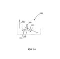
- FIG. 19 illustrates an optical assembly
- FIG. 20 illustrates an optical assembly
- FIGS. 21A and 21B illustrate an optical assembly
- FIG. 22 illustrates a multi-rotating laser shot pattern
- FIG. 23 illustrates an elliptical shaped shot.
- FIG. 24 illustrates a rectangular shaped spot.
- FIG. 25 illustrates a multi-shot shot pattern
- FIG. 26 illustrates a shot pattern
- FIGS. 27 to 36 illustrate LBHAs.
- the present inventions relate to methods, apparatus and systems for use in laser drilling of a borehole in the earth, and further, relate to equipment, methods and systems for the laser advancing of such boreholes deep into the earth and at highly efficient advancement rates. These highly efficient advancement rates are obtainable because the present invention provides for a means to get high power laser energy to the bottom of the borehole, even when the bottom is at great depths.
- FIG. 1 there is provided in FIG. 1 a high efficiency laser drilling system 1000 for creating a borehole 1001 in the earth 1002 .
- the term “earth” should be given its broadest possible meaning (unless expressly stated otherwise) and would include, without limitation, the ground, all natural materials, such as rocks, and artificial materials, such as concrete, that are or may be found in the ground, including without limitation rock layer formations, such as, granite, basalt, sandstone, dolomite, sand, salt, limestone, rhyolite, quartzite and shale rock.
- FIG. 1 provides a cut away perspective view showing the surface of the earth 1030 and a cut away of the earth below the surface 1002 .
- a source of electrical power 1003 which provides electrical power by cables 1004 and 1005 to a laser 1006 and a chiller 1007 for the laser 1006 .
- the laser provides a laser beam, i.e., laser energy, that can be conveyed by a laser beam transmission means 1008 to a spool of coiled tubing 1009 .
- a source of fluid 1010 is provided. The fluid is conveyed by fluid conveyance means 1011 to the spool of coiled tubing 1009 .
- the spool of coiled tubing 1009 is rotated to advance and retract the coiled tubing 1012 .
- the laser beam transmission means 1008 and the fluid conveyance means 1011 are attached to the spool of coiled tubing 1009 by means of rotating coupling means 1013 .
- the coiled tubing 1012 contains a means to transmit the laser beam 1030 along the entire length of the coiled tubing, i.e.,“long distance high power laser beam transmission means,” to the bottom hole assembly, 1014 .
- the coiled tubing 1012 also contains a means to convey the fluid 1031 along the entire length of the coiled tubing 1012 to the bottom hole assembly 1014 .
- a support structure 1015 which holds an injector 1016 , to facilitate movement of the coiled tubing 1012 in the borehole 1001 .
- Further other support structures may be employed for example such structures could be derrick, crane, mast, tripod, or other similar type of structure or hybrid and combinations of these.
- BOP blow out preventer
- the coiled tubing 1012 is passed from the injector 1016 through the diverter 1017 , the BOP 1018 , a wellhead 1020 and into the borehole 1001 .
- the fluid is conveyed to the bottom 1021 of the borehole 1001 . At that point the fluid exits at or near the bottom hole assembly 1014 and is used, among other things, to carry the cuttings, which are created from advancing a borehole, back up and out of the borehole.
- the diverter 1017 directs the fluid as it returns carrying the cuttings to the fluid and/or cuttings handling system 1019 through connector 1022 .
- This handling system 1019 is intended to prevent waste products from escaping into the environment and separates and cleans waste products and either vents the cleaned fluid to the air, if permissible environmentally and economically, as would be the case if the fluid was nitrogen, or returns the cleaned fluid to the source of fluid 1010 , or otherwise contains the used fluid for later treatment and/or disposal.
- the BOP 1018 serves to provide multiple levels of emergency shut off and/or containment of the borehole should a high-pressure event occur in the borehole, such as a potential blow-out of the well.
- the BOP is affixed to the wellhead 1020 .
- the wellhead in turn may be attached to casing.
- casing For the purposes of simplification the structural components of a borehole such as casing, hangers, and cement are not shown. It is understood that these components may be used and will vary based upon the depth, type, and geology of the borehole, as well as, other factors.
- the downhole end 1023 of the coiled tubing 1012 is connected to the bottom hole assembly 1014 .
- the bottom hole assembly 1014 contains optics for delivering the laser beam 1024 to its intended target, in the case of FIG. 1 , the bottom 1021 of the borehole 1001 .
- the bottom hole assembly 1014 for example, also contains means for delivering the fluid.
- this system operates to create and/or advance a borehole by having the laser create laser energy in the form of a laser beam.
- the laser beam is then transmitted from the laser through the spool and into the coiled tubing. At which point, the laser beam is then transmitted to the bottom hole assembly where it is directed toward the surfaces of the earth and/or borehole.
- the laser beam Upon contacting the surface of the earth and/or borehole the laser beam has sufficient power to cut, or otherwise effect, the rock and earth creating and/or advancing the borehole.
- the laser beam at the point of contact has sufficient power and is directed to the rock and earth in such a manner that it is capable of borehole creation that is comparable to or superior to a conventional mechanical drilling operation.
- this cutting occurs through spalling, thermal dissociation, melting, vaporization and combinations of these phenomena.
- the laser material interaction entails the interaction of the laser and a fluid or media to clear the area of laser illumination.
- the laser illumination creates a surface event and the fluid impinging on the surface rapidly transports the debris, i.e. cuttings and waste, out of the illumination region.
- the fluid is further believed to remove heat either on the macro or micro scale from the area of illumination, the area of post-illumination, as well as the borehole, or other media being cut, such as in the case of perforation.
- the fluid then carries the cuttings up and out of the borehole.
- the coiled tubing is unspooled and lowered further into the borehole. In this way the appropriate distance between the bottom hole assembly and the bottom of the borehole can be maintained. If the bottom hole assembly needs to be removed from the borehole, for example to case the well, the spool is wound up, resulting in the coiled tubing being pulled from the borehole.
- the laser beam may be directed by the bottom hole assembly or other laser directing tool that is placed down the borehole to perform operations such as perforating, controlled perforating, cutting of casing, and removal of plugs.
- This system may be mounted on readily mobile trailers or trucks, because its size and weight are substantially less than conventional mechanical rigs.
- the laser may be any high powered laser that is capable of providing sufficient energy to perform the desired functions, such advancing the borehole into and through the earth and rock believed to be present in the geology corresponding to the borehole.
- the laser source of choice is a single mode laser or low order multi-mode laser with a low M 2 to facilitate launching into a small core optical fiber, i.e. about 50 microns. However, larger core fibers are preferred.
- Examples of a laser source include fiber lasers, chemical lasers, disk lasers, thin slab lasers, high brightness diode lasers, as well as, the spectral beam combination of these laser sources or a coherent phased array laser of these sources to increase the brightness of the individual laser source.
- FIG. 4 Illustrates a spectral beam combination of lasers sources to enable high power transmission down a fiber by allocating a predetermined amount of power per color as limited by the Stimulated Brillioun Scattering (SBS) phenomena.
- a first laser source 4001 having a first wavelength of “x”, where x is less than 1 micron.
- a second laser 4002 having a second wavelength of x+ ⁇ 1 microns, where ⁇ 1 is a predetermined shift in wavelength, which shift could be positive or negative.
- a third laser 4003 having a third wavelength of x+ ⁇ 1 + ⁇ 2 microns and a fourth laser 4004 having a wavelength of x+ ⁇ 1 + ⁇ 2 + ⁇ 3 microns.
- the laser beams are combined by a beam combiner 4005 and transmitted by an optical fiber 4006 .
- the combined beam having a spectrum show in 4007 .
- FIG. 5 Illustrates a frequency modulated phased array of lasers.
- a master oscillator than can be frequency modulated, directly or indirectly, that is then used to injection-lock lasers or amplifiers to create a higher power composite beam than can be achieved by any individual laser.
- lasers 5001 , 5002 , 5003 , and 5004 which have the same wavelength.
- the laser beams are combined by a beam combiner 5005 and transmitted by an optical fiber 5006 .
- the lasers 5001 , 5002 , 5003 and 5004 are associated with a master oscillator 5008 that is FM modulated.
- the combined beam having a spectrum show in 5007 , where ⁇ is the frequency excursion of the FM modulation.
- Such lasers are disclosed in U.S. Pat. No. 5,694,408, the disclosure of which is incorporated here in reference in its entirety.
- the laser source may be a low order mode source (M 2 ⁇ 2)so it can be focused into an optical fiber with a mode diameter of ⁇ 100 microns.
- Optical fibers with small mode field diameters ranging from 50 microns to 6 microns have the lowest transmission losses. However, this should be balanced by the onset of non-linear phenomenon and the physical damage of the face of the optical fiber requiring that the fiber diameter be as large as possible while the transmission losses have to be as small as possible.
- the laser source should have total power of at least about 1 kW, from about 1 kW to about 20 kW, from about 10 kW to about 20 kW, at least about 10 kW, and preferably about 20 or more kW. Moreover, combinations of various lasers may be used to provide the above total power ranges. Further, the laser source should have beam parameters in mm millirad as large as is feasible with respect to bendability and manufacturing substantial lengths of the fiber, thus the beam parameters may be less than about 100 mm millirad, from single mode to about 50 mm millirad, less than about 50 mm millirad, less than about 15 mm millirad, and most preferably about 12 mm millirad.
- the laser source should have at least a 10% electrical optical efficiency, at least about 50% optical efficiency, at least about 70% optical efficiency, whereby it is understood that greater optical efficiency, all other factors being equal, is preferred, and preferably at least about 25%.
- the laser source can be run in either pulsed or continuous wave (CW) mode.
- the laser source is preferably capable of being fiber coupled.
- IPG 20000 YB having the following specifications set forth in Table 1 herein.
- the laser may be any of the above referenced lasers, and it may further be any smaller lasers that would be only used for workover and completion downhole activities.
- Laser selection may generally be based on the intended application or desired operating parameters. Average power, specific power, irradiance, operation wavelength, pump source, beam spot size, exposure time, and associated specific energy may be considerations in selecting a laser.
- the material to be drilled such as rock formation type, may also influence laser selection.
- the type of rock may be related to the type of resource being pursued. Hard rocks such as limestone and granite may generally be associated with hydrothermal sources, whereas sandstone and shale may generally be associated with gas or oil sources.
- the laser may be a solid-state laser, it may be a gas, chemical, dye or metal-vapor laser, or it may be a semiconductor laser. Further, the laser may produce a kilowatt level laser beam, and it may be a pulsed laser.
- the laser further may be a Nd:YAG laser, a CO 2 laser, a diode laser, such as an infrared diode laser, or a fiber laser, such as a ytterbium-doped multi-clad fiber laser.
- the infrared fiber laser emits light in the wavelengths ranges from 800 nm to 1600 nm.
- the fiber laser is doped with an active gain medium comprising rare earth elements, such as holmium, erbium, ytterbium, neodymium, dysprosium, praseodymium, thulium or combinations thereof. Combinations of one or more types of lasers may be implemented.
- rare earth elements such as holmium, erbium, ytterbium, neodymium, dysprosium, praseodymium, thulium or combinations thereof. Combinations of one or more types of lasers may be implemented.
- Fiber lasers of the type useful in the present invention are generally built around dual-core fibers.
- the inner core may be composed of rare-earth elements; ytterbium, erbium, thulium, holmium or a combination.
- the optical gain medium emits wavelengths of 1064 nm, 1360 nm, 1455 nm, and 1550 nm, and can be diffraction limited.
- An optical diode may be coupled into the outer core (generally referred to as the inner cladding) to pump the rare earth ion in the inner core.
- the outer core can be a multi-mode waveguide.
- the inner core serves two purposes: to guide the high power laser; and, to provide gain to the high power laser via the excited rare earth ions.
- the outer cladding of the outer core may be a low index polymer to reduce losses and protect the fiber.
- Typical pumped laser diodes emit in the range of about 915-980 nm (generally—940 nm).
- Fiber lasers are manufactured from IPG Photonics or Southhampton Photonics. High power fibers were demonstrated to produce 50 kW by IPG Photonics when multiplexed.
- one or more laser beams generated or illuminated by the one or more lasers may spall, vaporize or melt material, such as rock.
- the laser beam may be pulsed by one or a plurality of waveforms or it may be continuous.
- the laser beam may generally induce thermal stress in a rock formation due to characteristics of the material, such as rock including, for example, the thermal conductivity.
- the laser beam may also induce mechanical stress via superheated steam explosions of moisture in the subsurface of the rock formation. Mechanical stress may also be induced by thermal decompositions and sublimation of part of the in situ mineral of the material. Thermal and/or mechanical stress at or below a laser-material interface may promote spallation of the material, such as rock.
- the laser may be used to effect well casings, cement or other bodies of material as desired.
- a laser beam may generally act on a surface at a location where the laser beam contacts the surface, which may be referred to as a region of laser illumination.
- the region of laser illumination may have any preselected shape and intensity distribution that is required to accomplish the desired outcome, the laser illumination region may also be referred to as a laser beam spot.
- Boreholes of any depth and/or diameter may be formed, such as by spalling multiple points or layers. Thus, by way of example, consecutive points may be targeted or a strategic pattern of points may be targeted to enhance laser/rock interaction.
- the position or orientation of the laser or laser beam may be moved or directed so as to intelligently act across a desired area such that the laser/material interactions are most efficient at causing rock removal.
- One or more lasers may further be positioned downhole, i.e., down the borehole.
- the laser may be located at any depth within the borehole.
- the laser may be maintained relatively close to the surface, it may be positioned deep within the borehole, it may be maintained at a constant depth within the borehole or it may be positioned incrementally deeper as the borehole deepens.
- the laser may be maintained at a certain distance from the material, such as rock to be acted upon.
- the laser When the laser is deployed downhole, the laser may generally be shaped and/or sized to fit in the borehole.
- Some lasers may be better suited than others for use downhole. For example, the size of some lasers may deem them unsuitable for use downhole, however, such lasers may be engineered or modified for use downhole. Similarly, the power or cooling of a laser may be modified for use downhole.
- a borehole drilling system may include a cooling system.
- the cooling system may generally function to cool the laser.
- the cooling system may cool a downhole laser, for example to a temperature below the ambient temperature or to an operating temperature of the laser.
- the laser may be cooled using sorption cooling to the operating temperature of the infrared diode laser, for example, about 20° C. to about 100° C.
- the operating temperature may be between about 20° C. to about 50° C.
- a liquid at a lower temperature may be used for cooling when a temperature higher than the operating diode laser temperature is reached to cool the laser.
- Heat may also be sent uphole, i.e., out of the borehole and to the surface, by a liquid heat transfer agent.
- the liquid transfer agent may then be cooled by mixing with a lower temperature liquid uphole.
- One or multiple heat spreading fans may be attached to the laser diode to spread heat away from the infrared diode laser. Fluids may also be used as a coolant, while an external coolant may also be used.
- the laser may be protected from downhole pressure and environment by being encased in an appropriate material.
- materials may include steel, titanium, diamond, tungsten carbide and the like.
- the fiber head for an infrared diode laser or fiber laser may have an infrared transmissive window.
- Such transmissive windows may be made of a material that can withstand the downhole environment, while retaining transmissive qualities.
- One such material may be sapphire or other material with similar qualities.
- One or more infrared diode lasers or fiber lasers may be entirely encased by sapphire.
- an infrared diode laser or fiber laser may be made of diamond, tungsten carbide, steel, and titanium other than the part where the laser beam is emitted.
- the infrared diode laser or fiber laser is not in contact with the borehole while drilling.
- a downhole laser may be spaced from a wall of the borehole.
- the chiller which is used to cool the laser, in the systems of the general type illustrated in FIG. 1 is chosen to have a cooling capacity dependent on the size of the laser, the efficiency of the laser, the operating temperature, and environmental location, and preferably the chiller will be selected to operate over the entirety of these parameters.
- a chiller that is useful for a 20 kW laser will have the following specifications set forth in Table 2 herein.
- the laser beam is transmitted to the spool of coiled tubing by a laser beam transmission means.
- a transmittance means may be by a commercially available industrial hardened fiber optic cabling with QBH connectors at each end.
- this coiled conduit may be a hollow tube, it may be an optical fiber, it may be a bundle of optical fibers, it may be an armored optical fiber, it may be other types of optically transmitting cables or it may be a hollow tube that contains the aforementioned optically transmitting cables.
- the spool in this configuration has a hollow central axis where the optical power is transmitted to the input end of the optical fiber.
- the beam will be launched down the center of the spool, the spool rides on precision bearings, e.g., FIG. 6 , non-load bearing bearing 6008 , in either a horizontal or vertical orientation to prevent any tilt of the spool as the fiber is spooled out.
- the beam when launched into the fiber is launched by a lens which is rotating with the fiber at the Fourier Transform plane of the launch lens, which is insensitive to movement in the position of the lens with respect the laser beam, but sensitive to the tilt of the incoming laser beam.
- the beam, which is launched in the fiber is launched by a lens that is stationary with respect to the fiber at the Fourier Transform plane of the launch lens, which is insensitive to movement of the fiber with respect to the launch lens.
- a second approach is to use a stationary spool similar to a creel and rotate the laser head as the fiber spools out to keep the fiber from twisting as it is extracted from the spool. If the fiber can be designed to accept a reasonable amount of twist along its length, then this would be the preferred method. Using the second approach if the fiber could be pre-twisted around the spool then as the fiber is extracted from the spool, the fiber straightens out and there is no need for the fiber and the drill head to be rotated as the fiber is played out.
- the spool of coiled tubing can contain the following exemplary lengths of coiled tubing: from 1 km (3,280 ft) to 9 km (29,528 ft); from 2 km (6,561 ft) to 5 km (16,404 ft); at least about 5 km (16,404 ft); and from about 5 km (16,404 ft) to at least about 9 km (29,528 ft).
- the spool may be any standard type spool using 2.875 steel pipe.
- commercial spools typically include 4-6 km of steel 27 ⁇ 8′′ tubing, Tubing is available in commercial sizes ranging from 1′′ to 27 ⁇ 8′′.
- the Spool will have a standard type 27 ⁇ 8′′ hollow steel pipe, i.e., the coiled tubing.
- the coiled tubing will have in it at least one optical fiber for transmitting the laser beam to the bottom hole assembly.
- the coiled tubing may also carry other cables for other downhole purposes or to transmit material or information back up the borehole to the surface.
- the coiled tubing may also carry the fluid or a conduit for carrying the fluid. To protect and support the optical fibers and other cables that are carried in the coiled tubing stabilizers may be employed.
- the spool may have QBH fibers and a collimator. Vibration isolation means are desirable in the construction of the spool, and in particular for the fiber slip ring, thus for example the spool's outer plate mounts to the spool support using a Delrin plate, while the inner plate floats on the spool and pins rotate the assembly.
- the fiber slip ring is the stationary fiber, which communicates power across the rotating spool hub to the rotating fiber.
- the mechanical axis of the spool is used to transmit optical power from the input end of the optical fiber to the distal end.
- This calls for a precision optical bearing system (the fiber slip ring) to maintain a stable alignment between the external fiber providing the optical power and the optical fiber mounted on the spool.
- the laser can be mounted inside of the spool, or as shown in FIG. 1 it can be mounted external to the spool or if multiple lasers are employed both internal and external locations may be used.
- the internally mounted laser may be a probe laser, used for analysis and monitoring of the system and methods performed by the system. Further, sensing and monitoring equipment may be located inside of or otherwise affixed to the rotating elements of the spool.
- rotating coupling means to connect the coiled tubing, which is rotating, to the laser beam transmission means 1008 , and the fluid conveyance means 1011 , which are not rotating.
- a spool of coiled tubing 2009 has two rotating coupling means 2013 .
- One of said coupling means has an optical rotating coupling means 2002 and the other has a fluid rotating coupling means 2003 .
- the optical rotating coupling means 2002 can be in the same structure as the fluid rotating coupling means 2003 or they can be separate. Thus, preferably, two separate coupling means are employed. Additional rotating coupling means may also be added to handle other cables, such as for example cables for downhole probes.
- the optical rotating coupling means 2002 is connected to a hollow precision ground axle 2004 with bearing surfaces 2005 , 2006 .
- the laser transmission means 2008 is optically coupled to the hollow axle 2004 by optical rotating coupling means 2002 , which permits the laser beam to be transmitted from the laser transmission means 2008 into the hollow axle 2004 .
- the optical rotating coupling means for example may be made up of a QBH connector, a precision collimator, and a rotation stage, for example a Precitec collimator through a Newport rotation stage to another Precitec collimator and to a QBH collimator. To the extent that excessive heat builds up in the optical rotating coupling cooling should be applied to maintain the temperature at a desired level.
- the hollow axle 2004 then transmits the laser beam to an opening 2007 in the hollow axle 2004 , which opening contains an optical coupler 2010 that optically connects the hollow axle 2004 to the long distance high power laser beam transmission means 2025 that is located inside of the coiled tubing 2012 .
- the laser transmission means 2008 , the hollow axle 2004 and the long distance high power laser beam transmission means 2025 are rotatably optically connected, so that the laser beam can be transmitted from the laser to the long distance high power laser beam transmission means 2025 .
- FIG. 6 A further illustration of an optical connection for a rotation spool is provided in FIG. 6 , wherein there is illustrated a spool 6000 and a support 6001 for the spool 6000 .
- the spool 6000 is rotatably mounted to the support 6001 by load bearing bearings 6002 .
- An input optical cable 6003 which transmits a laser beam from a laser source (not shown in this figure) to an optical coupler 6005 .
- the laser beam exits the connector 6005 and passes through optics 6009 and 6010 into optical coupler 6006 , which is optically connected to an output optical cable 6004 .
- the fiber 6004 a can be encased in a buoyant casing 6004 b .
- the optical coupler 6005 is mounted to the spool by a preferably non-load bearing bearing 6008
- coupler 6006 is mounted to the spool by device 6007 in a manner that provides for its rotation with the spool.
- the load bearing bearing 6002 , front plate 6021 , and the non-load bearing bearing 6008 provide a vibrational isolation assembly 6020 . In this way as the spool is rotated, the weight of the spool and coiled tubing is supported by the load bearing bearings 6002 , while the rotatable optical coupling assembly 6022 allows the laser beam to be transmitted from cable 6003 which does not rotate to cable 6004 which rotates with the spool.
- FIGS. 3A and 3B there is provided a creel 3009 that is stationary and which contains coiled within the long distance high power laser beam transmission means 3025 . That means is connected to the laser beam transmission means 3008 , which is connected to the laser (not shown in this figure). In this way the laser beam may be transmitted into the long distance high power laser beam transmission means and that means may be deployed down a borehole. Similarly, the long distance high power laser beam transmission means may be contained within coiled tubing on the creel.
- the long distance means would be an armored optical cable of the type provided herein.
- the optical cable In using the creel consideration should be given to the fact that the optical cable will be twisted when it is deployed. To address this consideration the bottom hole assembly, or just the laser drill head, may be slowly rotated to keep the optical cable untwisted, the optical cable may be pre-twisted, and the optical cable may be designed to tolerate the twisting.
- the source of fluid may be either a gas, a liquid, a foam, or system having multiple capabilities.
- the fluid may serve many purposes in the advancement of the borehole.
- the fluid is primarily used for the removal of cuttings from the bottom of the borehole, for example as is commonly referred to as drilling fluid or drilling mud, and to keep the area between the end of the laser optics in the bottom hole assembly and the bottom of the borehole sufficiently clear of cuttings so as to not interfere with the path and power of the laser beam. It also may function to cool the laser optics and the bottom hole assembly, as well as, in the case of an incompressible fluid, or a compressible fluid under pressure.
- the fluid further provides a means to create hydrostatic pressure in the well bore to prevent influx of gases and fluids.
- the rate of removal of cuttings by the fluid not be a limiting factor to the systems rate of advancing a borehole.
- fluids that may be employed with the present invention include conventional drilling muds, water (provided they are not in the optical path of the laser), and fluids that are transmissive to the laser, such as halocarbons, (halocarbon are low molecular weight polymers of chlorotrifluoroethylene (PCTFE)), oils and N 2 .
- halocarbons halocarbon are low molecular weight polymers of chlorotrifluoroethylene (PCTFE)
- oils and N 2 e.g., oils, oils and N 2 .
- these fluids can be employed and preferred and should be delivered at rates from a couple to several hundred CFM at a pressure ranging from atmospheric to several hundred psi. If combinations of these fluids are used flow rates should be employed to balance the objects of maintaining the trasmissiveness of the optical path and removal of debris.
- the long distance high powered laser beam transmission means is an optical fiber or plurality of optical fibers in an armored casing to conduct optical power from about 1 kW to about 20 kW, from about 10 kW to about 20 kW, at least about 10 kW, and preferably about 20 or more kW average power down into a borehole for the purpose of sensing the lithology, testing the lithology, boring through the lithology and other similar applications relating in general to the creation, advancement and testing of boreholes in the earth.
- the armored optical fiber comprises a 0.64 cm (1 ⁇ 4′′) stainless steel tube that has 1, 2, 1 to 10, at least 2, more than 2, at least about 50, at least about 100, and most preferably between 2 to 15 optical fibers in it.
- these will be about 500 micron core diameter baseline step index fibers
- Industrial lasers use high power optical fibers armored with steel coiled around the fiber and a polymer jacket surrounding the steel jacket to prevent unwanted dust and dirt from entering the optical fiber environment.
- the optical fibers are coated with a thin coating of metal or a thin wire is run along with the fiber to detect a fiber break.
- a fiber break can be dangerous because it can result in the rupture of the armor jacket and would pose a danger to an operator.
- this type of fiber protection is designed for ambient conditions and will not withstand the harsh environment of the borehole.
- Fiber optic sensors for the oil and gas industry are deployed both unarmored and armored. At present it is believed that the currently available unarmored approaches are unacceptable for the high power applications contemplated by this application.
- the current manifestations of the armored approach are similarly inadequate, as they do not take into consideration the method for conducting high optical power and the method for detecting a break in the optical fiber, both of which are important for a reliable and safe system.
- the current method for armoring an optical fiber is to encase it in a stainless steel tube, coat the fiber with carbon to prevent hydrogen migration, and finally fill the tube with a gelatin that both cushions the fiber and absorbs hydrogen from the environment.
- this packaging has been performed with only small diameter core optical fibers (50 microns) and with very low power levels ⁇ 1 Watt optical power.
- a novel armored fiber and method to encase a large core optical fiber having a diameter equal to or greater than 50 microns, equal to or greater than 75 microns and most preferably equal to or greater than 100 microns, or a plurality of optical fibers into a metal tube, where each fiber may have a carbon coating, as well as a polymer, and may include Teflon coating to cushion the fibers when rubbing against each other during deployment.
- the fiber, or bundle of fibers can have a diameter of from about greater than or equal to 150 microns to about 700 microns, 700 microns to about 1.5 mm, or greater than 1.5 mm.
- the carbon coating can range in thicknesses from 10 microns to >600 microns.
- the polymer or Teflon coating can range in thickness from 10 microns to >600 microns and preferred types of such coating are acrylate, silicone, polyimide, PFA and others.
- the carbon coating can be adjacent the fiber, with the polymer or Teflon coating being applied to it. Polymer or Teflon coatings are applied last to reduce binding of the fibers during deployment.
- fiber optics may send up to 10 kW per a fiber, up to 20 kW per a fiber, up to and greater than 50 kw per fiber.
- the fibers may transmit any desired wavelength or combination of wavelengths. In some embodiments, the range of wavelengths the fiber can transmit may preferably be between about 800 nm and 2100 nm.
- the fiber can be connected by a connector to another fiber to maintain the proper fixed distance between one fiber and neighboring fibers. For example, fibers can be connected such that the beam spot from neighboring optical fibers when irradiating the material, such as a rock surface are under 2′′ and non-overlapping to the particular optical fiber.
- the fiber may have any desired core size.
- the core size may range from about 50 microns to 1 mm or greater.
- the fiber can be single mode or multimode. If multimode, the numerical aperture of some embodiments may range from 0.1 to 0.6. A lower numerical aperture may be preferred for beam quality, and a higher numerical aperture may be easier to transmit higher powers with lower interface losses.
- a fiber laser emitted light at wavelengths comprised of 1060 nm to 1080 nm, 1530 nm to 1600 nm, 1800 nm to 2100 nm, diode lasers from 800 nm to 2100 nm, CO 2 Laser at 10,600 nm, or Nd:YAG Laser emitting at 1064 nm can couple to the optical fibers.
- the fiber can have a low water content.
- the fiber can be jacketed, such as with polyimide, acrylate, carbon polyamide, and carbon/dual acrylate or other material. If requiring high temperatures, a polyimide or a derivative material may be used to operate at temperatures over 300 degrees Celsius.
- the fibers can be a hollow core photonic crystal or solid core photonic crystal. In some embodiments, using hollow core photonic crystal fibers at wavelengths of 1500 nm or higher may minimize absorption losses.
- the use of the plurality of optical fibers can be bundled into a number of configurations to improve power density.
- the optical fibers forming a bundle may range from two at hundreds of watts to kilowatt powers in each fiber to millions at milliwatts or microwatts of power.
- the plurality of optical fibers may be bundled and spliced at powers below 2.5 kW to step down the power.
- Power can be spliced to increase the power densities through a bundle, such as preferably up to 10 kW, more preferably up to 20 kW, and even more preferably up to or greater than 50 kW.
- the step down and increase of power allows the beam spot to increase or decrease power density and beam spot sizes through the fiber optics.
- splicing the power to increase total power output may be beneficial so that power delivered through fibers does not reach past the critical power thresholds for fiber optics.
- a thin wire may also be packaged, for example in the 1 ⁇ 4′′ stainless tubing, along with the optical fibers to test the fiber for continuity.
- a metal coating of sufficient thickness is applied to allow the fiber continuity to be monitored.
- the configurations in Table 3 can be of lengths equal to or greater than 1 m, equal to or greater than 1 km, equal to or greater than 2 km, equal to or greater than 3 km, equal to or greater than 4 km and equal to or greater than 5 km. These configuration can be used to transmit there through power levels from about 0.5 kW to about 10 kW, from greater than or equal to 1 kW, greater than or equal to 2 kW, greater than or equal to 5 kW, greater than or equal to 8 kW, greater than or equal to 10 kW and preferable at least about 20 kW.
- Raleigh Scattering is the intrinsic losses of the fiber due to the impurities in the fiber.
- Raman Scattering can result in Stimulated Raman Scattering in a Stokes or Anti-Stokes wave off of the vibrating molecules of the fiber.
- Raman Scattering occurs preferentially in the forward direction and results in a wavelength shift of up to +25 nm from the original wavelength of the source.
- the third mechanism Brillioun Scattering
- the Brillioun Scattering can give rise to Stimulated Brillioun Scattering (SBS) where the pump light is preferentially scattered backwards in the fiber with a frequency shift of approximately 1 to about 20 GHz from the original source frequency.
- SBS Stimulated Brillioun Scattering
- This Stimulated Brillioun effect can be sufficiently strong to backscafter substantially all of the incident pump light if given the right conditions. Therefore it is desirable to suppress this non-linear phenomenon.
- the threshold for SBS There are essentially four primary variables that determine the threshold for SBS: the length of the gain medium (the fiber); the linewidth of the source laser; the natural Brillioun linewidth of the fiber the pump light is propagating in; and, the mode field diameter of the fiber.
- the length of the fiber is inversely proportional to the power threshold, so the longer the fiber, the lower the threshold.
- the power threshold is defined as the power at which a high percentage of incident pump radiation will be scattered such that a positive feedback takes place whereby acoustic waves are generated by the scattering process. These acoustic waves then act as a grating to incite further SBS. Once the power threshold is passed, exponential growth of scattered light occurs and the ability to transmit higher power is greatly reduced.
- novel and unique means for suppressing nonlinear scattering phenomena such as the SBS and Stimulated Raman Scattering phenomena, means for increasing power threshold, and means for increasing the maximum transmission power are set forth for use in transmitting high power laser energy over great distances for, among other things, the advancement of boreholes.
- the mode field diameter needs to be as large as practical without causing undue attenuation of the propagating source laser.
- Large core single mode fibers are currently available with mode diameters up to 30 microns, however bending losses are typically high and propagation losses are higher than desired.
- Small core step index fibers, with mode field diameters of 50 microns are of interest because of the low intrinsic losses, the significantly reduced launch fluence and the decreased SBS gain because the fiber is not polarization preserving, it also has a multi-mode propagation constant and a large mode field diameter. All of these factors effectively increase the SBS power threshold. Consequently, a larger core fiber with low Raleigh Scattering losses is a potential solution for transmitting high powers over great distances, preferably where the mode field diameter is 50 microns or greater in diameter.
- the next consideration is the natural Brillioun linewidth of the fiber.
- the Brillioun linewidth can be broadened by varying the temperature along the length of the fiber, modulating the strain on the fiber and inducing acoustic vibrations in the fiber. Varying the temperature along the fiber results in a change in the index of refraction of the fiber and the background (kT) vibration of the atoms in the fiber effectively broadening the Brillioun spectrum.
- the temperature along the fiber will vary naturally as a result of the geothermal energy that the fiber will be exposed to as the depths ranges expressed herein. The net result will be a suppression of the SBS gain.
- Applying a thermal gradient along the length of the fiber could be a means to suppress SBS by increasing the Brillioun linewidth of the fiber.
- such means could include using a thin film heating element or variable insulation along the length of the fiber to control the actual temperature at each point along the fiber.
- Applied thermal gradients and temperature distributions can be, but are not limited to, linear, step-graded, and periodic functions along the length of the fiber.
- Modulating the strain for the suppression of nonlinear scattering phenomena, on the fiber can be achieved, but those means are not limited to anchoring the fiber in its jacket in such a way that the fiber is strained.
- the Brillioun spectrum will either red shift or blue shift from the natural center frequency effectively broadening the spectrum and decreasing the gain. If the fiber is allowed to hang freely from a tensioner, then the strain will vary from the top of the hole to the bottom of the hole, effectively broadening the Brillioun gain spectrum and suppressing SBS.
- Means for applying strain to the fiber include, but are not limited to, twisting the fiber, stretching the fiber, applying external pressure to the fiber, and bending the fiber.
- twisting the fiber can occur through the use of a creel.
- twisting of the fiber may occur through use of downhole stabilizers designed to provide rotational movement.
- Stretching the fiber can be achieved, for example as described above, by using support elements along the length of the fiber. Downhole pressures may provide a pressure gradient along the length of the fiber thus inducing strain.
- Acoustic modulation of the fiber can alter the Brillioun linewidth.
- acoustic generators such as piezo crystals along the length of the fiber and modulating them at a predetermined frequency
- the Brillioun spectrum can be broadened effectively decreasing the SBS gain.
- crystals, speakers, mechanical vibrators, or any other mechanism for inducing acoustic vibrations into the fiber may be used to effectively suppress the SBS gain.
- acoustic radiation can be created by the escape of compressed air through predefined holes, creating a whistle effect.
- the interaction of the source linewidth and the Brillioun linewidth in part defines the gain function. Varying the linewidth of the source can suppress the gain function and thus suppress nonlinear phenomena such as SBS.
- the source linewidth can be varied, for example, by FM modulation or closely spaced wavelength combined sources, an example of which is illustrated in FIG. 5 .
- a fiber laser can be directly FM modulated by a number of means, one method is simply stretching the fiber with a piezo-electric element which induces an index change in the fiber medium, resulting in a change in the length of the cavity of the laser which produces a shift in the natural frequency of the fiber laser.
- This FM modulation scheme can achieve very broadband modulation of the fiber laser with relatively slow mechanical and electrical components.
- a more direct method for FM modulating these laser sources can be to pass the beam through a non-linear crystal such as Lithium Niobate, operating in a phase modulation mode, and modulate the phase at the desired frequency for suppressing the gain.
- a spectral beam combination of laser sources which may be used to suppress Stimulated Brillioun Scattering.
- the spaced wavelength beams, the spacing as described herein can suppress the Stimulated Brillioun Scattering through the interference in the resulting acoustic waves, which will tend to broaden the Stimulated Brillioun Spectrum and thus resulting in lower Stimulated Brillioun Gain.
- the total maximum transmission power can be increased by limiting SBS phenomena within each color. An example of such a laser system is illustrated in FIG. 4 .
- Raman scattering can be suppressed by the inclusion of a wavelength-selective filter in the optical path.
- This filter can be a reflective, transmissive, or absorptive filter.
- an optical fiber connector can include a Raman rejection filter. Additionally a Raman rejection filter could be integral to the fiber.
- These filters may be, but are not limited to, a bulk filter, such as a dichroic filter or a transmissive grating filter, such as a Bragg grating filter, or a reflective grating filter, such as a ruled grating.
- any backward propagating Raman energy as well as, a means to introduce pump energy to an active fiber amplifier integrated into the overall fiber path, is contemplated, which, by way of example, could include a method for integrating a rejection filter with a coupler to suppress Raman Radiation, which suppresses the Raman Gain.
- Brillioun scattering can be suppressed by filtering as well.
- Faraday isolators for example, could be integrated into the system.
- a Bragg Grating reflector tuned to the Brillioun Scattering frequency could also be integrated into the coupler to suppress the Brillioun radiation.
- An active fiber amplifier can provide gain along the optical fiber to offset the losses in the fiber. For example, by combining active fiber sections with passive fiber sections, where sufficient pump light is provided to the active, i.e., amplified section, the losses in the passive section will be offset.
- a means to integrate signal amplification into the system In FIG. 7 there is illustrated an example of such a means having a first passive fiber section 8000 with, for example, ⁇ 1 dB loss, a pump source 8001 optically associated with the fiber amplifier 8002 , which may be introduced into the outer clad, to provide for example, a +1 dB gain of the propagating signal power.
- the fiber amplifier 8002 is optically connected to a coupler 8003 , which can be free spaced or fused, which is optically connected to a passive section 8004 .
- This configuration may be repeated numerous times, for varying lengths, power losses, and downhole conditions. Additionally, the fiber amplifier could act as the delivery fiber for the entirety of the transmission length.
- the pump source may be uphole, downhole, or combinations of uphole and downhole for various borehole configurations.
- a further method is to use dense wavelength beam combination of multiple laser sources to create an effective linewidth that is many times the natural linewidth of the individual laser effectively suppressing the SBS gain.
- multiple lasers each operating at a predetermined wavelength and at a predetermined wavelength spacing are superimposed on each other, for example by a grating.
- the grating can be transmissive or reflective.
- the optical fiber or fiber bundle can be encased in an environmental shield to enable it to survive at high pressures and temperatures.
- the cable could be similar in construction to the submarine cables that are laid across the ocean floor and maybe buoyant if the hole is filled with water.
- the cable may consist of one or many optical fibers in the cable, depending on the power handling capability of the fiber and the power required to achieve economic drilling rates. It being understood that in the field several km of optical fiber will have to be delivered down the borehole.
- the fiber cables maybe made in varying lengths such that shorter lengths are used for shallower depths so higher power levels can be delivered and consequently higher drilling rates can be achieved. This method requires the fibers to be changed out when transitioning to depths beyond the length of the fiber cable.
- a series of connectors could be employed if the connectors could be made with low enough loss to allow connecting and reconnecting the fiber(s) with minimal losses.
- the optical fibers are preferably placed inside the coiled tubing for advancement into and removal from the borehole.
- the coiled tubing would be the primary load bearing and support structure as the tubing is lowered into the well. It can readily be appreciated that in wells of great depth the tubing will be bearing a significant amount of weight because of its length.
- the optical fibers including the optical fiber bundle contained in the, for example, 1 ⁇ 4′′ stainless steel tubing, inside the coiled tubing stabilization devices are desirable.
- the coiled tubing supports can be located inside the coiled tubing that fix or hold the optical fiber in place relative to the coiled tubing.
- These supports should not interfere with, or otherwise obstruct, the flow of fluid, if fluid is being transmitted through the coiled tubing.
- An example of a commercially available stabilization system is the ELECTROCOIL System.
- the fibers may also be associated with the tubing by, for example, being run parallel to the tubing, and being affixed thereto, by being run parallel to the tubing and being slidably affixed thereto, or by being placed in a second tubing that is associated or not associated with the first tubing.
- various combinations of tubulars may be employed to optimize the delivery of laser energy, fluids, and other cabling and devices into the borehole.
- the optical fiber may be segmented and employed with conventional strands of drilling pipe and thus be readily adapted for use with a conventional mechanical drilling rig outfitted with connectable tubular drill pipe.
- the use of an optical pulse, train of pulses, or continuous signal that are continuously monitored that reflect from the distal end of the fiber and are used to determine the continuity of the fiber.
- the fluorescence from the illuminated surface as a means to determine the continuity of the optical fiber.
- a high power laser will sufficiently heat the rock material to the point of emitting light. This emitted light can be monitored continuously as a means to determine the continuity of the optical fiber.
- This method is faster than the method of transmitting a pulse through the fiber because the light only has to propagate along the fiber in one direction. Additionally there is provided the use of a separate fiber to send a probe signal to the distal end of the armored fiber bundle at a wavelength different than the high power signal and by monitoring the return signal on the high power optical fiber, the integrity of the fiber can be determined.
- These monitoring signals may transmit at wavelengths substantially different from the high power signal such that a wavelength selective filter may be placed in the beam path uphole or downhole to direct the monitoring signals into equipment for analysis.
- this selective filter may be placed in the creel or spool described herein.
- An Optical Spectrum Analyzer or Optical Time Domain Reflectometer or combinations thereof may be used.
- An AnaritsuMS9710C Optical Spectrum Analyzer having: a wavelength range of 600 nm-1.7 microns; a noise floor of 90 dBm @ 10 Hz, ⁇ 40 dBm @ 1 MHz; a 70 dB dynamic range at 1 nm resolution; and a maximum sweep width: 1200 nm and an Anaritsu CMA 4500 OTDR may be used.
- the efficiency of the laser's cutting action can also be determined by monitoring the ratio of emitted light to the reflected light.
- Materials undergoing melting, spallation, thermal dissociation, or vaporization will reflect and absorb different ratios of light.
- the ratio of emitted to reflected light may vary by material further allowing analysis of material type by this method.
- cutting efficiency, or both may be determined. This monitoring may be performed uphole, downhole, or a combination thereof.
- electrical power generation may take place in the borehole including at or near the bottom of the borehole.
- This power generation may take place using equipment known to those skilled in the art, including generators driven by drilling muds or other downhole fluids, means to convert optical to electrical power, and means to convert thermal to electrical power.
- the bottom hole assembly contains the laser optics, the delivery means for the fluid and other equipment.
- the bottom hole assembly contains the output end, also referred to as the distal end, of the long distance high power laser beam transmission means and preferably the optics for directing the laser beam to the earth or rock to be removed for advancing the borehole, or the other structure intended to be cut.
- the present systems and in particular the bottom hole assembly may include one or more optical manipulators.
- An optical manipulator may generally control a laser beam, such as by directing or positioning the laser beam to spall material, such as rock.
- an optical manipulator may strategically guide a laser beam to spall material, such as rock. For example, spatial distance from a borehole wall or rock may be controlled, as well as the impact angle.
- one or more steerable optical manipulators may control the direction and spatial width of the one or more laser beams by one or more reflective mirrors or crystal reflectors.
- the optical manipulator can be steered by an electro-optic switch, electroactive polymers, galvanometers, piezoelectrics, and/or rotary/linear motors.
- an infrared diode laser or fiber laser optical head may generally rotate about a vertical axis to increase aperture contact length.
- Various programmable values such as specific energy, specific power, pulse rate, duration and the like maybe implemented as a function of time.
- to apply energy may be strategically determined, programmed and executed so as to enhance a rate of penetration and/or laser/rock interaction, to enhance the overall efficiency of borehole advancement, and to enhance the overall efficiency of borehole completion, including reducing the number of steps on the critical path for borehole completion.
- One or more algorithms may be used to control the optical manipulator.
- the bottom hole assembly comprises an upper part 9000 and a lower part 9001 .
- the upper part 9000 may be connected to the lower end of the coiled tubing, drill pipe, or other means to lower and retrieve the bottom hole assembly from the borehole. Further, it may be connected to stabilizers, drill collars, or other types of downhole assemblies (not shown in the figure) which in turn are connected to the lower end of the coiled tubing, drill pipe, or other means to lower and retrieve the bottom hole assembly from the borehole.
- the upper part 9000 further contains the means 9002 that transmitted the high power energy down the borehole and the lower end 9003 of the means. In FIG. 8 this means is shown as a bundle of four optical cables.
- the upper part 9000 may also have air amplification nozzles 9005 that discharge a portion up to 100% of the fluid, for example N 2 .
- the upper part 9000 is joined to the lower part 9001 with a sealed chamber 9004 that is transparent to the laser beam and forms a pupil plane for the beam shaping optics 9006 in the lower part 9001 .
- the lower part 9001 may be designed to rotate and in this way for example an elliptical shaped laser beam spot can be rotated around the bottom of the borehole.
- the lower part 9001 has a laminar flow outlet 9007 for the fluid and two hardened rollers 9008 , 9009 at its lower end, although non-laminar flows and turbulent flows may be employed.
- the high energy laser beam for example greater than 10 kW, would travel down the fibers 9002 , exit the ends of the fibers 9003 and travel through the sealed chamber and pupil plane 9004 into the optics 9006 , where it would be shaped and focused into an elliptical spot.
- the laser beam would then strike the bottom of the borehole spalling, melting, thermally dissociating, and/or vaporizing the rock and earth struck and thus advance the borehole.
- the lower part 9001 would be rotating and this rotation would cause the elliptical laser spot to rotate around the bottom of the borehole.
- This rotation would also cause the rollers 9008 , 9009 to physically dislodge any material that was crystallized by the laser or otherwise sufficiently fixed to not be able to be removed by the flow of the fluid alone.
- the cuttings would be cleared from the laser path by the laminar flow of the fluid, as well as, by the action of the rollers 9008 , 9009 and the cuttings would then be carried up the borehole by the action of the fluid from the air amplifier 9005 , as well as, the laminar flow opening 9007 .
- the LBHA may contain an outer housing that is capable of withstanding the conditions of a downhole environment, a source of a high power laser beam, and optics for the shaping and directing a laser beam on the desired surfaces of the borehole, casing, or formation.
- the high power laser beam may be greater than about 1 kW, from about 2 kW to about 20 kW, greater than about 5 kW, from about 5 kW to about 10 kW, preferably at least about 10 kW, at least about 15 kW, and at least about 20 kW.
- the assembly may further contain or be associated with a system for delivering and directing fluid to the desired location in the borehole, a system for reducing or controlling or managing debris in the laser beam path to the material surface, a means to control or manage the temperature of the optics, a means to control or manage the pressure surrounding the optics, and other components of the assembly, and monitoring and measuring equipment and apparatus, as well as, other types of downhole equipment that are used in conventional mechanical drilling operations.
- the LBHA may incorporate a means to enable the optics to shape and propagate the beam which for example would include a means to control the index of refraction of the environment through which the laser is propagating.
- control and manage are understood to be used in their broadest sense and would include active and passive measures as well as design choices and materials choices.
- the LBHA should be construed to withstand the conditions found in boreholes including boreholes having depths of about 1,640 ft (0.5 km) or more, about 3,280 ft (1 km) or more, about 9,830 ft (3 km) or more, about 16,400 ft (5 km) or more, and up to and including about 22,970 ft (7 km) or more. While drilling, i.e. advancement of the borehole, is taking place the desired location in the borehole may have dust, drilling fluid, and/or cuttings present.
- the LBHA should be constructed of materials that can withstand these pressures, temperatures, flows, and conditions, and protect the laser optics that are contained in the LBHA. Further, the LBHA should be designed and engineered to withstand the downhole temperatures, pressures, and flows and conditions while managing the adverse effects of the conditions on the operation of the laser optics and the delivery of the laser beam.
- the LBHA should also be constructed to handle and deliver high power laser energy at these depths and under the extreme conditions present in these deep downhole environments.
- the LBHA and its laser optics should be capable of handling and delivering laser beams having energies of 1 kW or more, 5 kW or more, 10 kW or more and 20 kW or more.
- This assembly and optics should also be capable of delivering such laser beams at depths of about 1,640 ft (0.5 km) or more, about 3,280 ft (1 km) or more, about 9,830 ft (3 km) or more, about 16,400 ft (5 km) or more, and up to and including about 22,970 ft (7 km) or more.
- the LBHA should also be able to operate in these extreme downhole environments for extended periods of time.
- the lowering and raising of a bottom hole assembly has been referred to as tripping in and tripping out. While the bottom hole assembling is being tripped in or out the borehole is not being advanced.
- reducing the number of times that the bottom hole assembly needs to be tripped in and out will reduce the critical path for advancing the borehole, i.e., drilling the well, and thus will reduce the cost of such drilling. (As used herein the critical path referrers to the least number of steps that must be performed in serial to complete the well.) This cost savings equates to an increase in the drilling rate efficiency.
- the LBHA and its laser optics should be capable of handling and delivering laser beams having energies of 1 kW or more, 5 kW or more, 10 kW or more and 20 kW or more at depths of about 1,640 ft (0.5 km) or more, about 3,280 ft (1 km) or more, about 9,830 ft (3 km) or more, about 16,400 ft (5 km) or more, and up to and including about 22,970 ft (7 km) or more, for at least about 1 ⁇ 2 hr or more, at least about 1 hr or more, at least about 2 hours or more, at least about 5 hours or more, and at least about 10 hours or more, and preferably longer than any other limiting factor in the advancement of a borehole.
- using the LBHA of the present invention could reduce tripping activities to only those that are related to casing and completion activities, greatly reducing the cost for drilling the well.
- the cutting removal system may be typical of that used in an oil drilling system. These would include by way of example a shale shaker. Further, desanders and desilters and then centrifuges may be employed. The purpose of this equipment is to remove the cuttings so that the fluid can be recirculated and reused. If the fluid, i.e., circulating medium is gas, than a water misting systems may also be employed.
- FIG. 9 An illustration of an example of a LBHA configuration with two fluid outlet ports shown in the Figure.
- This example employees the use of fluid amplifiers and in particular for this illustration air amplifier techniques to remove material from the borehole.
- a section of an LBHA 9101 having a first outlet port 9103 , and a second outlet port 9105 .
- the second outlet port as configured, provides a means to amplify air, or a fluid amplification means.
- the first outlet port 9103 also provides an opening for the laser beam and laser path.
- the distance between the first outlet 9103 and the bottom of the borehole 9112 is shown by distance y and the distance between the second outlet port 9105 and the side wall of the borehole 9114 is shown by distance x.
- Having the curvature of the upper side 9115 of the second port 9105 is important to provide for the flow of the fluid to curve around and move up the borehole.
- having the angle 9116 formed by angled surface 9117 of the lower side 9119 is similarly important to have the boundary layer 9111 associate with the fluid flow 9109 .
- the second flow path 9109 is primarily responsible for moving waste material up and out of the borehole.
- the first flow path 9117 is primarily responsible for keeping the optical path optically open from debris and reducing debris in that path and further responsible for moving waste material from the area below the LBHA to its sides and a point where it can be carried out of the borehole by second flow 9105 .
- the ratio of the flow rates between the first and the second flow paths should be from about 100% for the first flow path, 1:1, 1:10, to 1:100.
- fluid amplifiers are exemplary and it should be understood that a LBHA, or laser drilling in general, may be employed without such amplifiers.
- fluid jets, air knives, or similar fluid directing means many be used in association with the LBHA, in conjunction with amplifiers or in lieu of amplifiers.
- a further example of a use of amplifiers would be to position the amplifier locations where the diameter of the borehole changes or the area of the annulus formed by the tubing and borehole change, such as the connection between the LBHA and the tubing.
- any number of amplifiers, jets or air knifes, or similar fluid directing devices may be used, thus no such devices may be used, a pair of such devices may be used, and a plurality of such devices may be use and combination of these devices may be used.
- the cuttings or waste that is created by the laser (and the laser-mechanical means interaction) have terminal velocities that must be overcome by the flow of the fluid up the borehole to remove them from the borehole.
- cuttings have terminal velocities of for sandstone waste from about 4 m/sec. to about 7 m/sec., granite waste from about 3.5 m/sec. to 7 m/sec., basalt waste from about 3 m/sec. to 8 m/sec., and for limestone waste less than 1 m/sec these terminal velocities would have to be overcome.
- FIG. 10 there is provided an example of a LBHA.
- a portion of a LBHA 100 having a first port 103 and a second port 105 .
- the second port 105 in comparison to the configuration of the example in FIG. 3 , is moved down to the bottom of the LBHA.
- There second port provides for a flow path 109 that can be viewed has two paths; an essentially horizontal path 113 and a vertical path 111 .
- There is also a flow path 107 which is primarily to keep the laser path optically clear of debris. Flow paths 113 and 107 combine to become part of path 111 .
- FIG. 12 There is provided in FIG. 12 an example of a rotating outlet port that may be part of or associated with a LBHA, or employed in laser drilling.
- a port 1201 having an opening 1203 .
- the port rotates in the direction of arrows 1205 .
- the fluid is then expelled from the port in two different angularly directed flow paths. Both flow paths are generally in the direction of rotation.
- a first flow path 1207 and a second flow path 1209 there is provided a first flow path 1207 and a second flow path 1209 .
- the first flow path has an angle “a” with respect to and relative to the outlet's rotation.
- the second flow path has an angle “b” with respect to and relative to the outlet's rotation.
- the fluid may act like a knife or pusher and assist in removal of the material.
- the illustrative outlet port of FIG. 12 may be configured to provide flows 1207 and 1209 to be in the opposite direction of rotation, the outlet may be configured to provide flow 1207 in the direction of the rotation and flow 1209 in a direction opposite to the rotation. Moreover, the outlet may be configured to provide a flow angles a and b that are the same or are different, which flow angles can range from 90° to almost 0° and may be in the ranges from about 80° to 10°, about 70° to 20°, about 60° to 30°, and about 50° to 40°, including variations of these where “a” is a different angle and/or direction than “b.”
- FIG. 13 There is provided in FIG. 13 an example of an air knife configuration that is associated with a LBHA.
- an air knife 1301 that is associated with a LBHA 1313 .
- the air knife and its related fluid flow can be directed in a predetermined manner, both with respect to angle and location of the flow.
- other fluid directing and delivery devices such as fluid jets may be employed.
- Test exposure times of 0.05 s, 0.1 s, 0.2 s, 0.5 s and 1 s will be used for granite and limestone. Power density will be varied by changing the beam spot diameter (circular) and elliptical area of 12.5 mm ⁇ 0.5 mm with a time-average power of 0.5 kW, 1.6 kW, 3 kW, 5 kW will be used. In addition to continuous wave beam, pulsed power will also be tested for spallation zones.
- Example 1 The general parameters of Example 1 will be repeated using sandstone and shale.
- Experimental Setup Fiber Laser IPG Photonics 5 kW ytterbium-doped mufti-clad fiber laser Berea Gray (or Yellow) 12′′ ⁇ 12′′ ⁇ 5′′ and 5′′ ⁇ 5′′ ⁇ 5′′ Sandstone Shale 12′′ ⁇ 12′′ ⁇ 5′′ and 5′′ ⁇ 5′′ ⁇ 5′′ Beam Type CW/Collimated Beam Spot Size (or 0.0625′′ (12.5 mm ⁇ 0.5 mm), 0.1′′ diameter) Power 0.25 kW, 0.5 kW, 1.6 kW, 3 kW, 5 kW Exposure Times 1 s, 0.5 s. 0.1 s
- Patterns utilizing a linear spot approximately 1 cm ⁇ 15.24 cm, an elliptical spot with major axis approximately 15.24 cm and minor axis approximately 1 cm, a single circular spot having a diameter of 1 cm, an array of spots having a diameter of 1 cm with the spacing between the spots being approximately equal to the spot diameter, the array having 4 spots spaced in a square, spaced along a line.
- the laser beam will be delivered to the rock surface in a shot sequence pattern wherein the laser is fired until spallation occurs and then the laser is directed to the next shot in the pattern and then fired until spallation occurs with this process being repeated.
- the spots are in effect rotated about their central axis.
- the spots may be rotated about their central axis, and rotated about an axis point as in the hands of a clock moving around a face.
- one or more laser beams may spall, chip, vaporize, or melt the material, such as rock in a pattern using an optical manipulator.
- the rock may be patterned by spalling to form rock fractures surrounding a segment of the rock to chip that piece of rock.
- the laser beam spot size may spall, vaporize, or melt the rock at one angle when interacting with rock at high power.
- the optical manipulator system may control two or more laser beams to converge at an angle so as to meet close to a point near a targeted piece of rock. Spallation may then form rock fractures overlapping and surrounding the target rock to chip the target rock and enable removal of larger rock pieces, such as incrementally.
- the laser energy may chip a piece of rock up to 1′′ depth and 1′′ width or greater.
- larger or smaller rock pieces may be chipped depending on factors such as the type of rock formation, and the strategic determination of the most efficient technique.
- one or more laser beams may form a ledge out of material, such as rock by spalling the rock in a pattern.
- One or more laser beams may spall rock at an angle to the ledge forming rock fractures surrounding the ledge to chip the piece of rock surrounding the ledge.
- Two or more beams may chip the rock to create a ledge.
- the laser beams can spall the rock at an angle to the ledge forming rock fractures surrounding the ledge to further chip the rock.
- Multiple rocks can be chipped simultaneously by more than one laser beams after one or more rock ledges are created to chip the piece of rock around the ledge or without a ledge by converging two beams near a point by spalling; further a technique known as kerfing may be employed.
- a fiber laser or liquid crystal laser may be optically pumped in a range from 750 nm to 2100 nm wavelength by an infrared laser diode.
- a fiber laser or liquid crystal laser may be supported or extend from the infrared laser diode downhole connected by an optical fiber transmitting from infrared diode laser to fiber laser or liquid crystal laser at the infrared diode laser wavelength.
- the fiber cable may be composed of a material such as silica, PMMA/perfluirnated polymers, hollow core photonic crystals, or solid core photonic crystals that are in single-mode or multimode.
- the optical fiber may be encased by a coiled tubing or reside in a rigid drill-string.
- the light may be transmitted from the infrared diode range from the surface to the fiber laser or liquid crystal laser downhole.
- One or more infrared diode lasers may be on the surface.
- a laser may be conveyed into the wellbore by a conduit made of coiled tubing or rigid drill-string.
- a power cable may be provided.
- a circulation system may also be provided. The circulation system may have a rigid or flexible tubing to send a liquid or gas downhole. A second tube may be used to raise the rock cuttings up to the surface.
- a pipe may send or convey gas or liquid in the conduit to another pipe, tube or conduit. The gas or liquid may create an air knife by removing material, such as rock debris from the laser head.
- a nozzle, such as a Laval nozzle may be included. For example, a Laval-type nozzle may be attached to the optical head to provide pressurized gas or liquid.
- the pressurized gas or liquid may be transmissive to the working wavelength of the infrared diode laser or fiber laser light to force drilling muds away from the laser path.
- Additional tubing in the conduit may send a lower temperature liquid downhole than ambient temperature at a depth to cool the laser in the conduit.
- One or more liquid pumps may be used to return cuttings and debris to the surface by applying pressure uphole drawing incompressible fluid to the surface.
- the drilling mud in the well may be transmissive to visible, near-IR range, and mid-IR wavelengths so that the laser beam has a clear optical path to the rock without being absorbed by the drilling mud.
- spectroscopic sample data may be detected and analyzed. Analysis may be conducted simultaneously while drilling from the heat of the rock being emitted. Spectroscopic samples may be collected by laser-induced breakdown derivative spectroscopy. Pulsed power may be supplied to the laser-rock impingement point by the infrared diode laser. The light may be analyzed by a single wavelength detector attached to the infrared diode laser. For example, Raman-shifted light may be measured by a Raman spectrometer.
- a tunable diode laser using a few-mode fiber Bragg grating may be implemented to analyze the band of frequencies of the fluid sample by using ytterbium, thulium, neodymium, dysprosium, praseodymium, or erbium as the active medium.
- a chemometric equation, or least mean square fit may be used to analyze the Raman spectra. Temperature, specific heat, and thermal diffusivity may be determined.
- data may be analyzed by a neural network. The neural network may be updated real-time while drilling. Updating the diode laser power output from the neural network data may optimize drilling performance through rock formation type.
- An apparatus to geo-navigate the well for logging may be included or associated with the drilling system.
- a magnemometer, 3-axis accelerometer, and/or gyroscope may be provided.
- the geo-navigation device may be encased, such as with steel, titanium, diamond, or tungsten carbide.
- the geo-navigation device may be encased together with the laser or independently.
- data from the geo-navigation device may direct the directional movement of the apparatus downhole from a digital signal processor.
- a high power optical fiber bundle may, by way of example, hang from an infrared diode laser or fiber laser downhole.
- the fiber may generally be coupled with the diode laser to transmit power from the laser to the rock formation.
- the infrared diode laser may be fiber coupled at a wavelength range between 800 nm to 1000 nm.
- the fiber optical head may not be in contact with the borehole.
- the optical cable may be a hollow core photonic crystal fiber, silica fiber, or plastic optical fibers including PMMA/perfluorinated polymers that are in single or multimode.
- the optical fiber may be encased by a coiled or rigid tubing.
- the optical fiber may be attached to a conduit with a first tube to apply gas or liquid to circulate the cuttings.
- a second tube may supply gas or liquid to, for example, a Laval nozzle jet to clear debris from the laser head.
- the ends of the optical fibers are encased in a head composed of a steerable optical manipulator and mirrors or crystal reflector.
- the encasing of the head may be composed of sapphire or a related material.
- An optical manipulator may be provided to rotate the optical fiber head.
- the infrared diode laser may be fully encased by steel, titanium, diamond, or tungsten carbide residing above the optical fibers in the borehole. In other embodiments, it may be partially encased.
- Single or multiple fiber optical cables may be tuned to wavelengths of the near-IR, mid-IR, and far-IR received from the infrared diode laser inducement of the material, such as rock for derivative spectroscopy sampling.
- a second optical head powered by the infrared diode laser above the optical head drilling may case the formation liner.
- the second optical head may extend from the infrared diode laser with light being transmitted through a fiber optic.
- the fiber optic may be protected by coiled tubing.
- the infrared diode laser optical head may perforate the steel and concrete casing.
- a second infrared diode laser above the first infrared diode laser may case the formation liner while drilling.
- a fiber laser or infrared diode laser downhole may transmit coherent light down a hollow tube without the light coming in contact with the tube when placed downhole.
- the hollow tube may be composed of any material.
- the hollow tube may be composed of steel, titanium or silica.
- a mirror or reflective crystal may be placed at the end of the hollow tube to direct collimated light to the material, such as a rock surface being drilled.
- the optical manipulator can be steered by an electro-optic switch, electroactive polymers, galvanometers, piezoelectrics, or rotary/linear motors.
- a circulation system may be used to raise cuttings.
- One or more liquid pumps may be used to return cuttings to the surface by applying pressure uphole, drawing incompressible fluid to the surface.
- the optical fiber may be attached to a conduit with two tubes, one to apply gas or liquid to circulate the cuttings and one to supply gas or liquid to a Laval nozzle jet to clear debris from the laser head.
- a drilling rig for making a borehole in the earth to a depth of from about 1 km to about 5 km or greater, the rig comprising an armored fiber optic delivery bundle, consisting of from 1 to a plurality of coated optical fibers, having a length that is equal to or greater than the depth of the borehole, and having a means to coil and uncoil the bundle while maintaining an optical connection with a laser source.
- the novel and innovative armored bundles and associated coiling and uncoiling apparatus and methods of the present invention may be used with conventional drilling rigs and apparatus for drilling, completion and related and associated operations.
- the apparatus and methods of the present invention may be used with drilling rigs and equipment such as in exploration and field development activities. Thus, they may be used with, by way of example and without limitation, land based rigs, mobile land based rigs, fixed tower rigs, barge rigs, drill ships, jack-up platforms, and semi-submersible rigs. They may be used in operations for advancing the well bore, finishing the well bore and work over activities, including perforating the production casing. They may further be used in window cutting and pipe cutting and in any application where the delivery of the laser beam to a location, apparatus or component that is located deep in the well bore may be beneficial or useful.
- FIGS. 14A and B which are collectively referred as FIG. 14 .
- a LBHA 14100 which has an upper part 1400 and a lower part 1401 .
- the upper part 1400 has housing 1418 and the lower part 1401 has housing 1419 .
- the LBHA 14100 , the upper part 1400 , the lower part 1401 and in particular the housings 1418 , 1419 should be constructed of materials and designed structurally to withstand the extreme conditions of the deep downhole environment and protect any of the components that are contained within them.
- the upper part 1400 may be connected to the lower end of the coiled tubing, drill pipe, or other means to lower and retrieve the LBHA 14100 from the borehole. Further, it may be connected to stabilizers, drill collars, or other types of downhole assemblies (not shown in the figure), which in turn are connected to the lower end of the coiled tubing, drill pipe, or other means to lower and retrieve the LBHA 14100 from the borehole.
- the upper part 1400 further contains, is connect to, or otherwise optically associated with the means 1402 that transmitted the high power laser beam down the borehole so that the beam exits the lower end 1403 of the means 1402 and ultimately exits the LBHA 14100 to strike the intended surface of the borehole.
- the beam path of the high power laser beam is shown by arrow 1415 .
- the means 1402 is shown as a single optical fiber.
- the upper part 1400 may also have air amplification nozzles 1405 that discharge the drilling fluid, for example N 2 , to among other things assist in the removal of cuttings up the borehole.
- a mud motor is the CAVO 1.7′′ diameter mud motor. This motor is about 7 ft long and has the following specifications: 7 horsepower @ 110 ft-lbs full torque; motor speed 0-700 rpm; motor can run on mud, air, N 2 , mist, or foam; 180 SCFM, 500-800 psig drop; support equipment extends length to 12 ft; 10:1 gear ratio provides 0-70 rpm capability; and has the capability to rotate the lower part 1401 of the LBHA through potential stall conditions.
- the upper part 1400 of the LBHA 14100 is joined to the lower part 1401 with a sealed chamber 1404 that is transparent to the laser beam and forms a pupil plane 1420 to permit unobstructed transmission of the laser beam to the beam shaping optics 1406 in the lower part 1401 .
- the lower part 1401 is designed to rotate.
- the sealed chamber 1404 is in fluid communication with the lower chamber 1401 through port 1414 .
- Port 1414 may be a one way valve that permits clean transmissive fluid and preferably gas to flow from the upper part 1400 to the lower part 1401 , but does not permit reverse flow, or if may be another type of pressure and/or flow regulating value that meets the particular requirements of desired flow and distribution of fluid in the downhole environment.
- a first fluid flow path shown by arrows 1416
- a second fluid flow path shown by arrows 1417 .
- the second fluid flow path is a laminar flow although other flows including turbulent flows may be employed.
- the lower part 1401 has a means for receiving rotational force from the motor 1410 , which in the example of the figure is a gear 1412 located around the lower part housing 1419 and a drive gear 1413 located at the lower end of the axle 1411 .
- Other means for transferring rotational power may be employed or the motor may be positioned directly on the lower part.
- an equivalent apparatus may be employed which provide for the rotation of the portion of the LBHA to facilitate rotation or movement of the laser beam spot while that he same time not providing undue rotation, or twisting forces, to the optical fiber or other means transmitting the high power laser beam down the hole to the LBHA. In his way laser beam spot can be rotated around the bottom of the borehole.
- the lower part 1401 has a laminar flow outlet 1407 for the fluid to exit the LBHA 14100 , and two hardened rollers 1408 , 1409 at its lower end.
- a laminar flow is contemplated in this example, it should be understood that non-laminar flows, and turbulent flows may also be employed.
- the two hardened rollers may be made of a stainless steel or a steel with a hard face coating such as tungsten carbide, chromium-cobalt-nickel alloy, or other similar materials. They may also contain a means for mechanically cutting rock that has been thermally degraded by the laser. They may range in length, i.e., from about 1 in to about 4 in and preferably are about 2-3 in and may be as large as or larger than 6 inches. Moreover in LBHAs for drilling larger diameter boreholes they may be in the range of 10-20 inches in diameter or greater.
- FIG. 14 provides for a high power laser beam path 1415 that enters the LBHA 14100 , travels through beam spot shaping optics 1406 , and then exits the LBHA to strike its intended target on the surface of a borehole.
- the beam spot shaping optics may also provide a rotational element to the spot, and if so, would be considered to be beam rotational and shaping spot optics.
- the high energy laser beam for example greater than 15 kW, would enter the LBHA 14100 , travel down fiber 1402 , exit the end of the fiber 1403 and travel through the sealed chamber 1404 and pupil plane 1420 into the optics 1406 , where it would be shaped and focused into a spot, the optics 1406 would further rotate the spot.
- the laser beam would then illuminate, in a potentially rotating manner, the bottom of the borehole spalling, chipping, melting, and/or vaporizing the rock and earth illuminated and thus advance the borehole.
- the lower part would be rotating and this rotation would further cause the rollers 1408 , 1409 to physically dislodge any material that was effected by the laser or otherwise sufficiently fixed to not be able to be removed by the flow of the drilling fluid alone.
- the cuttings would be cleared from the laser path by the flow of the fluid along the path 1417 , as well as, by the action of the rollers 1408 , 1409 and the cuttings would then be carried up the borehole by the action of the drilling fluid from the air amplifiers 1405 , as well as, the laminar flow opening 1407 .
- the configuration of the LBHA is FIG. 14 is by way of example and that other configurations of its components are available to accomplish the same results.
- the motor may be located in the lower part rather than the upper part, the motor may be located in the upper part but only turn the optics in the lower part and not the housing.
- the optics may further be located in both the upper and lower parts, which the optics for rotation being positioned in that part which rotates.
- the motor may be located in the lower part but only rotate the optics and the rollers. In this later configuration the upper and lower parts could be the same, i.e., there would only be one part to the LBHA.
- the inner portion of the LBHA may rotate while the outer portion is stationary or vice versa, similarly the top and/or bottom portions may rotate or various combinations of rotating and non-rotating components may be employed, to provide for a means for the laser beam spot to be moved around the bottom of the borehole.
- the optics 1406 should be selected to avoid or at least minimize the loss of power as the laser beam travels through them.
- the optics should further be designed to handle the extreme conditions present in the downhole environment, at least to the extent that those conditions are not mitigated by the housing 1419 .
- the optics may provide laser beam spots of differing power distributions and shapes as set forth herein above.
- the optics may further provide a sign spot or multiple spots as set forth herein above.
- Drilling may be conducted in a dry environment or a wet environment. An important factor is that the path from the laser to the rock surface should be kept as clear as practical of debris and dust particles or other material that would interfere with the delivery of the laser beam to the rock surface.
- the use of high brightness lasers provides another advantage at the process head, where long standoff distances from the last optic to the work piece are important to keeping the high pressure optical window clean and intact through the drilling process.
- the beam can either be positioned statically or moved mechanically, opto-mechanically, electro-optically, electromechanically, or any combination of the above to illuminate the earth region of interest.
- the LBHA may comprise a housing, which may by way of example, be made up of sub-housings. These sub-housings may be integral, they may be separable, they may be removably fixedly connected, they may be rotatable, or there may be any combination of one or more of these types of relationships between the sub-housings.
- the LBHA may be connected to the lower end of the coiled tubing, drill pipe, or other means to lower and retrieve the LBHA from the borehole.
- the LBHA may also have associated with, or in, it means to handle and deliver drilling fluids. These means may be associated with some or all of the sub-housings.
- mechanical scraping means e.g. a PDC bit, to remove and/or direct material in the borehole, although other types of known bits and/or mechanical drilling heads by also be employed in conjunction with the laser beam.
- These scrapers or bits may be mechanically interacted with the surface or parts of the borehole to loosen, remove, scrap or manipulate such borehole material as needed. These scrapers may be from less than about 1 in to about 20 in.
- the high energy laser beam for example greater than 15 kW, would travel down the fibers through optics and then out the lower end of the LBHA to illuminate the intended part of the borehole, or structure contained therein, spalling, melting and/or vaporizing the material so illuminated and thus advance the borehole or otherwise facilitating the removal of the material so illuminated.
- FIGS. 15A and 15B there is provided a graphic representation of an example of a laser beam-borehole surface interaction.
- a laser beam 1500 an area of beam illumination 1501 , i.e., a spot (as used herein unless expressly provided otherwise the term “spot” is not limited to a circle), on a borehole wall or bottom 1502 .
- a spot as used herein unless expressly provided otherwise the term “spot” is not limited to a circle
- FIG. 1B There is further provided in FIG. 1B a more detailed representation of the interaction and a corresponding chart 1510 categorizing the stress created in the area of illumination.
- Chart 1510 provides von Mises Stress in ⁇ M 10 8 N/m 2 wherein the cross hatching and shading correspond to the stress that is created in the illuminated area for a 30 mill-second illumination period, under down hole conditions of 2000 psi and a temperature of 150 F, with a beam having a fluence of 2 kW/cm 2 . Under these conditions the compressive strength of basalt is about 2.6 ⁇ 10 8 N/m 2 , and the cohesive strength is about 0.66 ⁇ 10 8 N/m 2 .
- the profiles of the beam interaction with the borehole to obtain a maximum amount of stress in the borehole in an efficient manner, and thus, increase the rate of advancement of the borehole can be obtained.
- an elliptical spot is rotated about its center point for a beam that is either uniform or Gaussian
- the energy deposition profile is illustrated in FIGS. 16A and 16B .
- the area of the borehole from the center point of the beam is shown as x and y axes 1601 and 1602 and the amount of energy deposited is shown on the z axis 1603 . From this it is seen that inefficiencies are present in the deposition of energy to the borehole, with the outer sections of the borehole 1605 and 1606 being the limiting factor in the rate of advancement.
- FIG. 17A and 17B An example of such a preferred beam deposition profile is provided in FIG. 17A and 17B , where FIG. 17A shows the energy deposition profile with no rotation, and FIG. 17B shows the energy deposition profile when the beam profile of 17 A is rotated through one rotation, i.e., 360 degrees; having x and y axes 1701 and 1702 and energy on z axis 1703 . This energy deposition distribution would be considered substantially uniform.
- FIGS. 18A to 18D having x and y axes 1801 and 1802 and z axis 1803 , wherein there is provided a laser beam 1805 having a plurality of rays 1807 .
- the laser beam 1805 enters an optical assembly 1820 , having a culminating lens 1809 , having input curvature 1811 and an output curvature 1813 .
- the optical assembly of Example 1 would provide a desired beam intensity profile from an input beam having a substantially Gaussian, Gaussian, or super-Gaussian distribution for applying the beam spot to a borehole surface 1830 .
- FIG. 19 A further example is illustrated in FIG. 19 and has an optical assembly 1920 for providing the desired beam intensity profile of FIGS. 17A and energy deposition of FIG. 17B to a borehole surface from a laser beam having a uniform distribution.
- a laser beam 1905 having a uniform profile and rays 1907 , that enters a spherical lens 1913 , which collimates the output of the laser from the downhole end of the fiber, the beam then exits 1913 and enters a toroidal lens 1915 , which has power in the x-axis to form the minor-axis of the elliptical beam.
- the beam then exits 1915 and enters a pair of aspherical toroidal lens 1917 , which has power in the y-axis to map the y-axis intensity profiles form the pupil plane to the image plane.
- the beam then exits the lens 1917 and enters flat window 1919 , which protects the optics from the outside environment.
- FIG. 20 provides a further optical assembly for providing predetermined beam energy profiles.
- a laser beam 205 having rays 207 , which enters collimating lens 209 , spot shape forming lens 211 , which is preferably an ellipse, and a micro optic array 213 .
- the micro optic array 213 may be a micro-prism array, or a micro lens array. Further the micro optic array may be specifically designed to provide a predetermined energy deposition profile, such as the profile of FIGS. 17 .
- FIG. 21 provides an optical assembly for providing a predetermined beam pattern.
- a laser beam 2105 exiting the downhole end of fiber 2140 , having rays 2107 , which enters collimating lens 2109 , a diffractive optic 2111 , which could be a micro optic, or a corrective optic to a micro optic, that provides pattern 2120 , which may but not necessary pass through reimaging lens 2113 , which provides pattern 2121 .
- the first and second axis of rotation simultaneously rotate around the center of the borehole 2212 in a rotational direction, shown by arrows 2212 , that is preferably in counter-rotation to the direction of rotation 2208 , 2204 .
- 2212 should be counter-clockwise. This shot pattern provides for a substantially uniform energy deposition.
- one or more fiber optic distal fiber ends may be arranged in a pattern.
- the multiplexed beam shape may comprise a cross, an x shape, a viewfinder, a rectangle, a hexagon, lines in an array, or a related shape where lines, squares, and cylinders are connected or spaced at different distances.
- one or more refractive lenses, diffractive elements, transmissive gratings, and/or reflective lenses may be added to focus, scan, and/or change the beam spot pattern from the beam spots emitting from the fiber optics that are positioned in a pattern.
- One or more refractive lenses, diffractive elements, transmissive gratings, and/or reflective lenses may be added to focus, scan, and/or change the one or more continuous beam shapes from the light emitted from the beam shaping optics.
- a collimator may be positioned after the beam spot shaper lens in the transversing optical path plane.
- the collimator may be an aspheric lens, spherical lens system composed of a convex lens, thick convex lens, negative meniscus, and bi-convex lens, gradient refractive lens with an aspheric profile and achromatic doublets.
- the collimator may be made of the said materials, fused silica, ZnSe, SF glass, or a related material.
- the collimator may be coated to reduce or enhance reflectivity or transmission. Said optical elements may be cooled by a purging liquid or gas.
- lens and optic(al) elements as used herein is used in its broadest terms and thus may also refer to any optical elements with power, such as reflective, transmissive or refractive elements,
- the refractive positive lens may be a microlens.
- the microlens can be steered in the light propagating plane to increase/decrease the focal length as well as perpendicular to the light propagating plane to translate the beam.
- the microlens may receive incident light to focus to multiple foci from one or more optical fibers, optical fiber bundle pairs, fiber lasers, diode lasers; and receive and send light from one or more collimators, positive refractive lenses, negative refractive lenses, one or more mirrors, diffractive and reflective optical beam expanders, and prisms.
- a diffractive optical element beam splitter could be used in conjunction with a refractive lens.
- the diffractive optical element beam splitter may form double beam spots or a pattern of beam spots comprising the shapes and patterns set forth above.
- a system and method for creating a borehole in the earth employ means for providing the laser beam to the bottom surface in a predetermined energy deposition profile, including having thee laser beam as delivered from the bottom hole assembly illuminating the bottom surface of the borehole with a predetermined energy deposition profile, illuminating the bottom surface with an any one of or combination of: a predetermined energy deposition profile biased toward the outside area of the borehole surface; a predetermined energy deposition profile biased toward the inside area of the borehole surface; a predetermined energy deposition profile comprising at least two concentric areas having different energy deposition profiles; a predetermined energy deposition profile provided by a scattered laser shot pattern; a predetermined energy deposition profile based upon the mechanical stresses applied by a mechanical removal means; a predetermined energy deposition profile having at least two areas of differing energy and the energies in the areas correspond inversely to the mechanical forces applied by a mechanical means.
- a method of advancing a borehole using a laser comprising: advancing a high power laser beam transmission means into a borehole; the borehole having a bottom surface, a top opening, and a length extending between the bottom surface and the top opening of at least about 1000 feet; the transmission means comprising a distal end, a proximal end, and a length extending between the distal and proximal ends, the distal end being advanced down the borehole; the transmission means comprising a means for transmitting high power laser energy; providing a high power laser beam to the proximal end of the transmission means; transmitting substantially all of the power of the laser beam down the length of the transmission means so that the beam exits the distal end; transmitting the laser beam from the distal end to an optical assembly in a laser bottom hole assembly, the laser bottom hole assembly directing the laser beam to the bottom surface of the borehole; and, providing a predetermined energy deposition profile to the bottom of the borehole; whereby the length of the borehole
- a method of advancing a borehole using a laser wherein the laser beam is directed to the bottom surface of the borehole in a substantially uniform energy deposition profile and thereby the length of the borehole is increased, in part, based upon the interaction of the laser beam with the bottom of the borehole.
- a method for laser drilling using an optical pattern to chip rock formations may comprise irradiating the rock to spall, melt, or vaporize with one or more lasing beam spots, beam spot patterns and beam shapes at non-overlapping distances and timing patterns to induce overlapping thermal rock fractures that cause rock chipping of rock fragments.
- Single or multiple beam spots and beam patterns and shapes may be formed by refractive and reflective optics or fiber optics.
- the optical pattern, the pattern's timing, and spatial distance between non-overlapping beam spots and beam shapes may be controlled by the rock type thermal absorption at specific wavelength, relaxation time to position the optics, and interference from rock removal.
- a beam spot pattern may comprise three or more beam spots in a grid pattern, a rectangular grid pattern, a hexagonal grid pattern, lines in an array pattern, a circular pattern, a triangular grid pattern, a cross grid pattern, a star grid pattern, a swivel grid pattern, a viewfinder grid pattern or a related geometrically shaped pattern.
- each lasing beam spot in the beam spot pattern has an area in the range of 0.1 cm 2 and 25 cm 2 . To chip the rock formation all the neighboring lasing beam spots to each lasing beam spot in the beam spot pattern may be less than a fixed position of 2′′ and non-overlapping in one or more aspects.
- a beam shape may be a continuous optical beam spot forming a geometrical shape that comprises of, a cross shape, hexagonal shape, a spiral shape, a circular shape, a triangular shape, a star shape, a line shape, a rectangular shape, or a related continuous beam spot shape.
- positioning one line either linear or non-linear to one or more neighboring lines either linear or non-linear at a fixed distance less than 2′′ and non-overlapping may be used to chip the rock formation.
- Lasing the rock surface with two or more beam shapes may be used to chip the rock formation.
- the relaxation times when moving the one or more beam spot shapes to their next subsequent lasing location may range between 0.05 ms and 2 s.
- rock fractures may be created to promote chipping away of rock segments for efficient borehole drilling.
- beam spots, shapes, and patterns may be used to create the rock fractures so as to enable multiple rock segments to be chipped away.
- the rock fractures may be strategically patterned.
- drilling rock formations may comprise applying one or more non-overlapping beam spots, shapes, or patterns to create the rock fractures. Selection of one or more beam spots, shapes, and patterns may generally be based on the intended application or desired operating parameters. Average power, specific power, timing pattern, beam spot size, exposure time, associated specific energy, and optical generator elements may be considerations when selecting one or more beam spots, a shape, or a pattern.
- the material to be drilled, such as rock formation type may also influence the one or more beam spot, a shape, or a pattern selected to chip the rock formation. For example, shale will absorb light and convert to heat at different rates than sandstone.
- rock may be patterned with one or more beam spots.
- beam spots may be considered one or more beam spots moving from one location to the next subsequent location lasing the rock surface in a timing pattern.
- Beam spots may be spaced apart at any desired distance.
- the fixed position between one beam spot and neighboring beam spots may be non-overlapping.
- the distance between neighboring beam spots may be less than 2′′.
- rock may be patterned with one or more beam shapes.
- beam shapes may be continuous optical shapes forming one or more geometric patterns.
- a pattern may comprise the geometric shapes of a line, cross, viewfinder, swivel, star, rectangle, hexagon, circular, ellipse, squiggly line, or any other desired shape or pattern.
- Elements of a beam shape may be spaced apart at any desired distance.
- the fixed position between each line linear or non-linear and the neighboring lines linear or non-linear are in a fixed position may be less than 2′′ and non-overlapping.
- rock may be patterned with a beam pattern.
- Beam patterns may comprise a grid or array of beam spots that may comprise the geometric patterns of line, cross, viewfinder, swivel, star, rectangle, hexagon, circular, ellipse, squiggly line. Beam spots of a beam pattern may be spaced apart at any desired distance. In some non-limiting aspects, the fixed position between each beam spot and the neighboring beam spots in the beam spot pattern may be less than 2′′ and non-overlapping.
- the beam spot being scanned may have any desired area.
- the area may be in a range between about 0.1 cm 2 and about 25 cm 2 .
- the beam line may have any desired specific diameter and any specific and predetermined power distribution.
- the specific diameter of some non-limiting aspects may be in a range between about 0.05 cm 2 and about 25 cm 2 .
- the maximum length of a line may generally be the diameter of a borehole to be drilled. Any desired wavelength may be used.
- the wavelength of one or more beam spots, a shape, or pattern may range from 800 nm to 2000 nm. Combinations of one or more beam spots, shapes, and patterns are possible and may be implemented.
- the timing patterns and location to chip the rock may vary based on known rock chipping speeds and/or rock removal systems.
- relaxation scanning times when positioning one or more beam spot patterns to their next subsequent lasing location may range between 0.05 ms and 2 s.
- a camera using fiber optics or spectroscopy techniques can image the rock height to determine the peak rock areas to be chipped.
- the timing pattern can be calibrated to then chip the highest peaks of the rock surface to lowest or peaks above a defined height using signal processing, software recognition, and numeric control to the optical lens system.
- timing patterns can be defined by a rock removal system.
- the timing should be chipping the rock from left to right to avoid rock removal interference to the one or more beam spots, shape, or pattern lasing the rock formation or vice-a-versa.
- the rock at the center should be chipped first and the direction of rock chipping should move then away from the center.
- the speed of rock removal will define the relaxation times.
- the rock surface may be affected by the gas or fluids used to clear the head and raise the cuttings downhole.
- heat from the optical elements and losses from the fiber optics downhole or diode laser can be used to increase the temperature of the borehole. This could lower the required temperature to induce spallation making it easier to spall rocks.
- a liquid may saturate the chipping location, in this situation the liquid would be turned to steam and expand rapidly, this rapid expansion would thus create thermal shocks improving the growth of fractures in the rock.
- an organic, volatile components, minerals or other materials subject to rapid and differential heating from the laser energy may expand rapidly, this rapid expansion would thus create thermal shocks improving the growth of fractures in the rock.
- the fluids of higher index of refraction may be sandwiched between two streams of liquid with lower index of refraction.
- the fluids used to clear the rock can act as a wavelength to guide the light.
- a gas may be used with a particular index of refraction lower than a fluid or another gas.
- the thermal shocks can range from lasing powers between one and another beam spot, shape, or pattern.
- the thermal shocks may reach 10 kW/cm 2 of continuous lasing power density.
- the thermal shocks may reach up to 10 MW/cm 2 of pulsed lasing power density, for instance, at 10 nanoseconds per pulse.
- two or more beam spots, shapes, and patterns may have different power levels to thermally shock the rock. In this way, a temperature gradient may be formed between lasing of the rock surface.
- FIG. 28 illustrates removing rock segments by sweeping liquid or gas flow 2801 when chipping a rock formation 2802 .
- the rock segments are chipped by a pattern 1606 of non-overlapping beam spot shaped lines 2803 , 2804 , 2805 .
- the optical head 2807 optically associated with an optical fiber bundle, the optical head 2807 having an optical element system irradiates the rock surface 2808 .
- a sweeping from left to right with gas or liquid flow 2801 raises the rock fragments 2809 chipped by the thermal shocks to the surface.
- FIG. 29 illustrates removing rock segments by liquid or gas flow directed from the optical head when chipping a rock formation 2901 .
- the rock segments are chipped by a pattern 2902 of non-overlapping beam spot shaped lines 2903 , 2904 , 2905 .
- the optical head 2907 with an optical element system irradiates the rock surface 2908 .
- Rock segment debris 2909 is swept from a nozzle 2915 flowing a gas or liquid 2911 from the center of the rock formation and away.
- the optical head 2907 is shown attached to a rotating motor 2920 and fiber optics 2924 spaced in a pattern.
- the optical head also has rails 2928 for z-axis motion if necessary to focus.
- the optical refractive and reflective optical elements form the beam path.
- FIG. 30 illustrates optical mirrors scanning a lasing beam spot or shape to chip a rock formation in the XY-plane.
- a first motor of rotating 3001 a plurality of fiber optics in a pattern 3003 , a gimbal 3005 , a second rotational motor 3007 and a third rotational motor 3010 .
- the second rotational motor 3007 having a stepper motor 3011 and a mirror 3015 associated therewith.
- the third rotational motor 3010 having a stepper motor 3013 and a mirror 3017 associated therewith.
- the optical elements 3019 optically associated with optical fibers 3003 and capable of providing laser beam along optical path 3021 .
- the gimbal rotates around the z-axis and repositions the mirrors in the XY-plane.
- the mirrors are attached to a stepper motor to rotate stepper motors and mirrors in the XY-plane.
- fiber optics are spaced in a pattern forming three beam spots manipulated by optical elements that scan the rock formation a distance apart and non-overlapping to cause rock chipping. Other fiber optic patterns, shapes, or a diode laser can be used.
- FIG. 31 illustrates using a beam splitter lens to form multiple beam foci to chip a rock formation.
- fibers 3101 in a pattern a rail 3105 for providing z direction movement shown by arrow 3103 , a fiber connector 3107 , an optical head 3109 , having a beam expander 3119 , which comprises a DOE/ROE 3115 , a positive lens 3117 , a collimator 3113 , a beam expander 3111 .
- This assembly is capable of delivering one or more laser beams, as spots 3131 in a pattern, along optical paths 3129 to a rock formation 3123 having a surface 3125 .
- Fiber optics are spaced a distance apart in a pattern.
- An optical element system composed of a beam expander and collimator feed a diffractive optical element attached to a positive lens to focus multiple beam spots to multiple foci.
- the distance between beam spots are non-overlapping and will cause chipping.
- rails move in the z-axis to focus the optical path.
- the fibers are connected by a connector.
- an optical element can be attached to each fiber optic as shown in this figure to more than one fiber optics.
- FIG. 32 illustrates using a beam spot shaper lens to shape a pattern to chip a rock formation.
- the optical head having a rail 3203 for facilitating movement in the z direction, shown by arrow 3205 , a fiber connector 3207 , an optics assembly 3201 for shaping the laser beam that is transmitted by the fibers 3201 .
- the optical head capable of transmitting a laser beam along optical path 3213 to illuminate a surface 3219 with a laser beam shot pattern 3221 that has separate, but intersection lines in a grid like pattern. Fiber optics are spaced a distance apart in a pattern connected by a connector.
- the fiber optics emit a beam spot to a beam spot shaper lens attached to the fiber optic.
- the beam spot shaper lens forms a line in this figure overlapping to form a tick-tack-toe laser pattern on the rock surface.
- the optical fiber bundle wires are attached to rails moving in the z-axis to focus the beam spots.
- FIG. 33 illustrates using a F-theta objective to focus a laser beam pattern to a rock formation to cause chipping.
- an optical head 3301 There is provided an optical head 3301 , a first motor for providing rotation 3303 , a plurality of optical fibers 3305 , a connector 3307 , which positions the fibers in a predetermined pattern 3309 .
- the laser beam exits the fibers and travels along optical path 3311 through F-Theta optics 3315 and illuminates rock surface 3313 in shot pattern 3310 .
- rails 3317 for providing z-direction movement. Fiber optics connected by connectors in a pattern are rotated in the z-axis by a gimbal attached to the optical casing head.
- the beam path is then refocused by an F-theta objective to the rock formation.
- the beam spots are a distance apart and non-overlapping to induce rock chipping in the rock formation.
- a rail is attached to the optical fibers and F-theta objective moving in the z-axis to focus the beam spot size.
- z-direction movement i.e. movement toward or away from the bottom of the borehole may be obtained by other means, for example winding and unwinding the spool or raising and lowering the drill string that is used to advance the LBHA into or remove the LBHA from the borehole.
- FIG. 34 illustrates mechanical control of fiber optics attached to beam shaping optics to cause rock chipping.
- a bundle of a plurality of fibers 3401 first motor 3405 for providing rotational movement a power cable 3403 , an optical head 3406 , and rails 3407 .
- a second motor 3409 There is further provided a fiber connector 3413 and a lens 3421 for each fiber to shape the beam.
- the laser beams exit the fibers and travel along optical paths 3415 and illumate the rock surface 3419 in a plurality of individual line shaped shot patterns 3417 .
- Fiber optics are connected by connectors in a pattern and are attached to a rotating gimbal motor around the z-axis.
- Rails are attached to the motor moving in the z-axis.
- the rails are structurally attached to the optical head casing and a support rail.
- a power cable powers the motors.
- the fiber optics emit a beam spot to a beam spot shaper lens forming three non-overlapping lines to the rock formation to induce rock chipping.
- FIG. 35 illustrates using a plurality of fiber optics to form a beam shape line.
- an optical assembly 3511 having a source of laser energy 3501 , a power cable 3503 , a first rotational motor 3505 , which is mounted as a gimbal, a second motor 3507 , and rails 3517 for z-direction movement.
- a plurality of fiber bundles 3521 with each bundle containing a plurality of individual fibers 3523 .
- the bundles 3521 are held in a predetermined position by connector 3525 .
- Each bundle 3521 is optically associated with a beam shaping optics 3509 .
- the motors 3507 , 3505 provide for the ability to move the plurality of beam spots in a plurality of predetermined and desired patterns on the surface 3519 , which may be the surface the borehole, such as the bottom surface, side surface, or casing in the borehole.
- a plurality of fiber optics are connected by connectors in a pattern and are attached to a rotating gimbal motor around the z-axis. Rails are attached to the motor moving in the z-axis. The rails are structurally attached to the optical head casing and a support rail.
- a power cable powers the motors.
- the plurality of fiber optics emits a beam spot to a beam spot shaper lens forming three lines that are non-overlapping to the rock formation.
- the beam shapes induce rock chipping.
- FIG. 36 illustrates using a plurality of fiber optics to form multiple beam spot foci being rotated on an axis.
- a laser source 3601 There is provided a laser source 3601 , a first motor 3603 , which is gimbal mounted, a second motor 3605 and a means for z-direction movement 3607 .
- a plurality of fiber bundles 3613 and a connector 3609 for positioning the plurality of bundles 3613 the laser beam exits the fibers and illuminates a surface in a diverging and crossing laser shot pattern.
- the fiber optics are connected by connectors at an angle being rotated by a motor attached to a gimbal that is attached to a second motor moving in the z-axis on rails.
- the motors receive power by a power cable.
- the rails are attached to the optical casing head and support rail beam.
- a collimator sends the beam spot originating from the plurality of optical fibers to a beam splitter.
- the beam splitter is a diffractive optical element that is attached to positive refractive lens.
- the beam splitter forms multiple beam spot foci to the rock formation at non-overlapping distances to chip the rock formation. The foci is repositioned in the z-axis by the rails.
- FIG. 11 illustrates scanning the rock surface with a beam pattern and XY scanner system.
- An optical path 1101 for a laser beam a scanner 1103 , a diffractive optics 1105 and a collimator optics 1107 .
- An optical fiber emits a beam spot that is expanded by a beam expander unit and focused by a collimator to a refractive optical element.
- the refractive optical element is positioned in front of an XY scanner unit to form a beam spot pattern or shape.
- the XY scanner composed of two mirrors controlled by galvanometer mirrors 1109 irradiate the rock surface 1113 to induce chipping.
Abstract
Description
| TABLE 1 |
| Optical Characteristics |
| Characteristics | Test conditions | Symbol | Min. | Typ. | Max | Unit |
| Operation Mode | CW, QCW | |
| Polarization | Random |
| Nominal Output Power | PNOM | 20000* | W | |||
| Output Power Tuning Range | 10 | 100 | % | |||
| Emission Wavelength | POUT = 20 kW | 1070 | 1080 | nm | ||
| Emission Linewidth | POUT = 20 |
3 | 6 | nm | ||
| Switching ON/OFF Time | POUT = 20 kW | 80 | 100 | μsec | ||
| Output Power Modulation Rate | POUT = 20 kW | 5.0 | kHz | |||
| Output Power Stability | Over 8 hrs, | 1.0 | 2.0 | % | ||
| TWATER = | ||||||
| Const |
| Feeding Fiber Core Diameter | 200 | μm |
| Beam Parameter Product | 200 μm | BPP | 12 | 14 | mm * mrad | ||
| Feeding Fiber | |||||||
| Fiber Length | L | 10 | m | ||||
| Fiber Cable Bend Radius: | |||||||
| | R | 100 | mm | ||||
| stressed | 200 |
| Output Termination | IPG HLC-8 Connector | |
| (QBH compatible) |
| Aiming Laser Wavelength | 640 | 680 | nm | |||
| Aiming Laser Output Power | 0.5 | 1 | mW | |||
| Parameters | Test conditions | Min. | Typ. | Max | Unit |
| Operation Voltage (3 phases) | 440 V | 480 | 520 | VAC | |
| Frequency | 50/60 | Hz |
| Power Consumption | POUT = 20 kW | 75 | 80 | kW | |
| Operating Temperature Range | +15 | +40 | ° C. | ||
| Humidity: | |||||
| without conditioner | T < 25° C. | 90 | % | ||
| with built-in conditioner | T < 40° C. | 95 | |||
| Storage Temperature | Without water | −40 | +75 | ° C. |
| Dimensions, H × W × D | NEMA-12; IP-55 | 1490 × 1480 × 810 | mm |
| Weight | 1200 | kg |
| Plumbing | NPT Threaded Stainless Steel | |
| and/or Plastic Tubing | ||
| *Output power tested at connector at distance not greater than 50 meters from laser. | ||
| TABLE 2 | |
| Chiller | PC400.01-NZ-DIS |
| Technical Data for 60 Hz operation: | |
| IPG-Laser type | |
| Cooling capacity net | YLR-15000, YLR-20000 |
| Refrigerant | 60.0 kW |
| Necessary air flow | R407C |
| Installation | 26100 m3/h |
| Number of compressors | Outdoor installation |
| Number of |
2 |
| Number of |
3 |
| 2 | |
| Operation Limits | |
| Designed Operating Temperature | 33° C. (92 F.) |
| Operating Temperature min. | (−) 20° C. (−4 F.) |
| Operating Temperature max. | 39° C. (102 F.) |
| Storage Temperature min. (with empty water | (−) 40° C. (−40 F.) |
| tank) | |
| Storage Temperature max. | 70° C. (158 F.) |
| Tank volume regular water | 240 Liter (63.50 Gallon) |
| Tank volume DI water | 25 Liter (6.61 Gallon) |
| Electrical Data for 60 Hz operation: | |
| Designed power consumption without heater | 29.0 kW |
| Designed power consumption with heater | 33.5 kW |
| Power consumption max. | 41.0 kW |
| Current max. | 60.5 A |
| Fuse max. | 80.0 A |
| Starting current | 141.0 A |
| Connecting voltage | 460 V/3 Ph/PE |
| Frequency | 60 Hz |
| Tolerance connecting voltage | +/−10% |
| Dimensions, weights and sound level | |
| Weight with empty tank | 900 KG (1984 lbs) |
| Sound level at distance of 5 m | 68 dB(A) |
| Width | 2120 mm (83½ inches) |
| Depth | 860 mm (33⅞ inches) |
| Height | 1977 mm (77⅞ inches) |
| Tap water circuit | 0 |
| Cooling capacity | 56.0 kW |
| Water outlet temperature | 21° C. (70 F.) |
| Water inlet temperature | 26° C. (79 F.) |
| Temperature stability | +/−1.0 K |
| Water flow vs. water pressure free available | 135 l/min at 3.0 bar (35.71 |
| GPM at 44 PSI) | |
| Water flow vs. water pressure free available | 90 l/min at 1.5 bar |
| (23.81 GPM at 21 PSI) | |
| De-ionized water circuit | |
| Cooling capacity | 4.0 kW |
| Water outlet temperature | 26° C. (79 F.) |
| Water inlet temperature | 31° C. (88 F.) |
| Temperature stability | +/−1.0 K |
| Water flow vs. water pressure free available | 20 l/min at 1.5 bar |
| (5.28 GPM at 21 PSI) | |
| Water flow vs. water pressure free available | 15 l/min at 4.0 bar |
| (3.96 GPM at 58 PSI) | |
| Options (included) | |
| Bifrequent version: | |
| 400 V/3 Ph/50 Hz | |
| 460 V/3 Ph 60 Hz | |
| TABLE 3 | ||
| Number of | ||
| Diameter of bundle | fibers in |
|
| 100 |
1 | |
| 200 microns-1 |
2 to 100 | |
| 100 microns-1 |
1 | |
| TABLE 4 | ||||
| Power | # of fibers | |||
| in | Length of fiber(s) | Diameter of bundle | in bundle | Power out |
| 20 kW | 5 km | 500 |
1 | 15 kW |
| 20 kW | 7 km | 500 |
1 | 13 kW |
| 20 kW | 5 km | 200 microns-1 |
2 to 100 | 15 kW |
| 20 kW | 7 km | 200 microns-1 |
2 to 100 | 13 kW |
| 20 kW | 5 km | 100-200 |
1 | 10 kW |
| 20 kW | 7 km | 100-200 |
1 | 8 kW |
| TABLE 5 |
| (with active amplification) |
| Power | # of fibers | |||
| in | Length of fiber(s) | Diameter of bundle | in bundle | Power out |
| 20 kW | 5 km | 500 |
1 | 17 kW |
| 20 kW | 7 km | 500 |
1 | 15 kW |
| 20 kW | 5 km | 200 microns-1 |
2 to 100 | 20 kW |
| 20 kW | 7 km | 200 microns-1 |
2 to 100 | 18 kW |
| 20 kW | 5 km | 100-200 |
1 | 15 kW |
| 20 kW | 7 km | 100-200 |
1 | 13 kW |
| Experimental Setup |
| Fiber Laser | IPG Photonics 5 kW ytterbium-doped |
| multi-clad fiber laser | |
| Dolomite/Barre Granite | 12″ × 12″ × 5″ or and 5″ × 5″ × 5″ |
| Rock Size | |
| Limestone | 12″ × 12″ × 5″ or and 5″ × 5″ × 5″ |
| Beam Spot Size (or | 0.3585″, 0.0625″ (12.5 mm, 0.5 mm), 0.1″, |
| diameter) | |
| Exposure Times | 0.05 s, 0.1 s, 0.2 s, 0.5 s, 1 s |
| Time-average Power | 0.25 kW, 0.5 kW, 1.6 kW, 3 kW, 5 kW |
| Pulse | 0.5 J/pulse to 20 J/pulse at 40 to 600 1/s |
| The general parameters of Example 1 will be repeated using sandstone |
| and shale. Experimental Setup |
| Fiber Laser | IPG Photonics 5 kW ytterbium-doped | |
| mufti-clad fiber laser | ||
| Berea Gray (or Yellow) | 12″ × 12″ × 5″ and 5″ × 5″ × 5″ | |
| Sandstone | ||
| Shale | 12″ × 12″ × 5″ and 5″ × 5″ × 5″ | |
| Beam Type | CW/Collimated | |
| Beam Spot Size (or | 0.0625″ (12.5 mm × 0.5 mm), 0.1″ | |
| diameter) | ||
| Power | 0.25 kW, 0.5 kW, 1.6 kW, 3 kW, 5 kW | |
| Exposure Times | 1 s, 0.5 s. 0.1 s | |
| Experimental Setup |
| Fixed: |
| Fiber Laser | IPG Photonics 5 kW ytterbium-doped multi-clad | |
| fiber laser | ||
| Dolomite/Barre | 12″ × 12″ × 12″ and 12″ × 12″ × 24″ | |
| Granite Rock Size | ||
| Limestone | 12″ × 12″ × 12″ and 12″ × 12″ × 24″ | |
| Berea Gray (or | 12″ × 12″ × 12″ and 12″ × 12″ × 24″ | |
| Yellow) | ||
| Sandstone | ||
| Shale | 12″ × 12″ × 12″ and 12″ × 12″ × 24″ | |
| Beam Type | CW/Collimated and Pulsed at Spallation Zones | |
| Specific Power | Spallation zones (920 W/cm2 at ~2.6 kJ/cc for | |
| Sandstone & 4 kW/cm2 at ~0.52 kJ/cc for Limestone) | ||
| Beam Size | 12.5 mm × 0.5 mm | |
| Exposure | See Experiments | 1 & 2 |
| Purging | 189 l/min Nitrogen Flow | |
| Experimental Setup |
| Fiber Laser | IPG Photonics 5 kW ytterbium-doped multi- | |
| clad fiber laser | ||
| Dolomite/Barre Granite | 5″ × 5″ × 5″ | |
| Rock Size | ||
| Limestone | 5″ × 5″ × 5″ | |
| Berea Gray (or Yellow) | 5″ × 5″ × 5″ | |
| Sandstone | ||
| Shale | 5″ × 5″ × 5″ | |
| Beam Type | CW/Collimated or Pulsed at Spallation | |
| Zones | ||
| Specific Power | Spallation zones (~920 W/cm2 at ~2.6 kJ/cc | |
| for Sandstone & 4 kW/cm2 at ~0.52 kJ/cc for | ||
| Limestone) | ||
| Beam Size | 12.5 mm × 0.5 mm | |
| Exposure | See Experiments | 1 & 2 |
| Purging | 1891/min Nitrogen Flow | |
| Distance between two | 0.2″, 0.5″, 1″, 1.5″ | |
| laser beams | ||
| Experimental Setup |
| Fiber Laser | IPG Photonics 5 kW ytterbium-doped | |
| multi-clad fiber laser | ||
| Dolomite/Barre Granite | 12″ × 12″ × 12″ and 12″ × 12″ × 5″ | |
| Rock Size | ||
| Limestone | 12″ × 12″ × 12″ and 12″ × 12″ × 5″ | |
| Berea Gray (or Yellow) | 12″ × 12″ × 12″ and 12″ × 12″ × 5″ | |
| Sandstone | ||
| Shale | 12″ × 12″ × 12″ and 12″ × 12″ × 5″ | |
| Beam Type | CW/Collimated or Pulsed at Spallation | |
| Zones | ||
| Specific Power | Spallation zones {~920 W/cm2 at −2.6 kJ/cc | |
| for Sandstone & 4 kW/cm2 at | ||
| ~0.52 kJ/cc for Limestone) | ||
| Beam Size | 12.5 mm × 0.5 mm | |
| Exposure | See Experiments | 1 & 2 |
| Purging | 189 l/min Nitrogen Flow | |
| Drilling | |||
| type/Laser | |||
| power down | |||
| Depth | Rock type | hole | |
| Drill 17½ | Surface - | Sand and | Conventional |
| inch hole | 3000 ft | shale | mechanical |
| drilling | |||
| Run 13⅜ | Length 3000 ft | ||
| inch casing | |||
| Drill 12¼ inch | 3000 ft-8,000 ft | basalt | 40 kW |
| hole | (minimum) | ||
| Run 9⅝ inch | Length 8,000 ft | ||
| casing | |||
| Drill 8½ inch | 8,000 ft-11,000 ft | limestone | Conventional |
| hole | mechanical | ||
| drilling | |||
| Run 7 inch | Length 11,000 ft | ||
| casing | |||
| Drill 6¼ inch | 11,000 ft-14,000 ft | Sand stone | Conventional |
| hole | mechanical | ||
| drilling | |||
| Run 5 inch | Length 3000 ft | ||
| liner | |||
| Drilling | |||
| type/Laser | |||
| power down | |||
| Depth | Rock type | hole | |
| Drill 17½ | Surface - | Sand and | Conventional |
| inch hole | 500 ft | shale | mechanical |
| drilling | |||
| Run 13⅜ | Length 500 ft | ||
| casing | |||
| Drill 12¼ hole | 500 ft-4,000 ft | granite | 40 kW |
| (minimum) | |||
| Run 9⅝ inch | Length 4,000 ft | ||
| casing | |||
| Drill 8½ inch | 4,000 ft-11,000 ft | basalt | 20 kW |
| hole | (minimum) | ||
| Run 7 inch | Length 11,000 ft | ||
| casing | |||
| Drill 6¼ inch | 11,000 ft-14,000 ft | Sand stone | Conventional |
| hole | mechanical | ||
| drilling | |||
| Run 5 inch | Length 3000 ft | ||
| liner | |||
Claims (54)
Priority Applications (37)
| Application Number | Priority Date | Filing Date | Title |
|---|---|---|---|
| US12/543,986 US8826973B2 (en) | 2008-08-20 | 2009-08-19 | Method and system for advancement of a borehole using a high power laser |
| US13/211,729 US20120067643A1 (en) | 2008-08-20 | 2011-08-17 | Two-phase isolation methods and systems for controlled drilling |
| US13/222,931 US20120074110A1 (en) | 2008-08-20 | 2011-08-31 | Fluid laser jets, cutting heads, tools and methods of use |
| US13/366,882 US9138786B2 (en) | 2008-10-17 | 2012-02-06 | High power laser pipeline tool and methods of use |
| US13/403,132 US20120261188A1 (en) | 2008-08-20 | 2012-02-23 | Method of high power laser-mechanical drilling |
| US13/403,692 US9027668B2 (en) | 2008-08-20 | 2012-02-23 | Control system for high power laser drilling workover and completion unit |
| US13/403,509 US9360631B2 (en) | 2008-08-20 | 2012-02-23 | Optics assembly for high power laser tools |
| US13/403,615 US9562395B2 (en) | 2008-08-20 | 2012-02-23 | High power laser-mechanical drilling bit and methods of use |
| US13/565,345 US9089928B2 (en) | 2008-08-20 | 2012-08-02 | Laser systems and methods for the removal of structures |
| US13/782,869 US9719302B2 (en) | 2008-08-20 | 2013-03-01 | High power laser perforating and laser fracturing tools and methods of use |
| US13/782,942 US9244235B2 (en) | 2008-10-17 | 2013-03-01 | Systems and assemblies for transferring high power laser energy through a rotating junction |
| US13/966,969 US9669492B2 (en) | 2008-08-20 | 2013-08-14 | High power laser offshore decommissioning tool, system and methods of use |
| US14/080,722 US9545692B2 (en) | 2008-08-20 | 2013-11-14 | Long stand off distance high power laser tools and methods of use |
| US14/082,026 US10053967B2 (en) | 2008-08-20 | 2013-11-15 | High power laser hydraulic fracturing, stimulation, tools systems and methods |
| US14/105,949 US9664012B2 (en) | 2008-08-20 | 2013-12-13 | High power laser decomissioning of multistring and damaged wells |
| US14/139,680 US10195687B2 (en) | 2008-08-20 | 2013-12-23 | High power laser tunneling mining and construction equipment and methods of use |
| US14/214,304 US10301912B2 (en) | 2008-08-20 | 2014-03-14 | High power laser flow assurance systems, tools and methods |
| US14/330,980 US20150308194A1 (en) | 2008-08-20 | 2014-07-14 | Method and system for advancement of a borehole using a high power laser |
| US14/803,228 US9492885B2 (en) | 2008-08-20 | 2015-07-20 | Laser systems and apparatus for the removal of structures |
| US14/958,864 US10199798B2 (en) | 2008-08-20 | 2015-12-03 | Downhole laser systems, apparatus and methods of use |
| US14/997,072 US20160187588A1 (en) | 2008-10-17 | 2016-01-15 | System and assemblies for transferring high power laser energy through a rotating junction |
| US15/064,165 US20160186524A1 (en) | 2009-08-19 | 2016-03-08 | Subsea in situ laser for laser assisted blow out preventer and methods of use |
| US15/140,412 US20170059854A1 (en) | 2008-08-20 | 2016-04-27 | Optics assembly for high power laser tools |
| US15/349,914 US10953491B2 (en) | 2008-08-20 | 2016-11-11 | High power laser offshore decommissioning tool, system and methods of use |
| US15/445,238 US20170191314A1 (en) | 2008-08-20 | 2017-02-28 | Methods and Systems for the Application and Use of High Power Laser Energy |
| US15/603,192 US10711580B2 (en) | 2008-08-20 | 2017-05-23 | High power laser decommissioning of multistring and damaged wells |
| US15/612,679 US20170266760A1 (en) | 2008-08-20 | 2017-06-02 | High Power Laser Offshore Decommissioning Tool, System and Methods of Use |
| US15/656,976 US10683703B2 (en) | 2008-08-20 | 2017-07-21 | High power laser perforating and laser fracturing tools and methods of use |
| US16/058,546 US20190040726A1 (en) | 2008-08-20 | 2018-08-08 | High power laser hydraulic fracturing, stimulation, tools systems and methods |
| US16/237,691 US11590606B2 (en) | 2008-08-20 | 2019-01-01 | High power laser tunneling mining and construction equipment and methods of use |
| US16/267,327 US20190178036A1 (en) | 2008-08-20 | 2019-02-04 | Downhole laser systems, apparatus and methods of use |
| US16/409,815 US20190383120A1 (en) | 2008-08-20 | 2019-05-11 | High power laser flow assurance systems, tools and methods |
| US16/786,600 US20200232309A1 (en) | 2008-08-20 | 2020-02-10 | High power laser hydraulic fracturing, stimulation, tools systems and methods |
| US16/807,016 US11060378B2 (en) | 2008-08-20 | 2020-03-02 | High power laser flow assurance systems, tools and methods |
| US16/901,276 US11761265B2 (en) | 2008-08-20 | 2020-06-15 | High power laser perforating and laser fracturing tools and methods of use |
| US17/209,105 US20220105592A1 (en) | 2009-08-19 | 2021-03-22 | High power laser offshore decommissioning tool, system and methods of use |
| US18/114,869 US20230321749A1 (en) | 2008-08-20 | 2023-02-27 | High power laser tunneling mining and construction equipment and methods of use |
Applications Claiming Priority (5)
| Application Number | Priority Date | Filing Date | Title |
|---|---|---|---|
| US9038408P | 2008-08-20 | 2008-08-20 | |
| US10273008P | 2008-10-03 | 2008-10-03 | |
| US10647208P | 2008-10-17 | 2008-10-17 | |
| US15327109P | 2009-02-17 | 2009-02-17 | |
| US12/543,986 US8826973B2 (en) | 2008-08-20 | 2009-08-19 | Method and system for advancement of a borehole using a high power laser |
Related Parent Applications (9)
| Application Number | Title | Priority Date | Filing Date |
|---|---|---|---|
| US12/544,136 Continuation-In-Part US8511401B2 (en) | 2008-08-20 | 2009-08-19 | Method and apparatus for delivering high power laser energy over long distances |
| US12/544,094 Continuation-In-Part US8424617B2 (en) | 2008-08-20 | 2009-08-19 | Methods and apparatus for delivering high power laser energy to a surface |
| US12/544,038 Continuation-In-Part US8820434B2 (en) | 2008-08-20 | 2009-08-19 | Apparatus for advancing a wellbore using high power laser energy |
| US13/366,882 Continuation-In-Part US9138786B2 (en) | 2008-08-20 | 2012-02-06 | High power laser pipeline tool and methods of use |
| US13/403,741 Continuation-In-Part US20120273470A1 (en) | 2008-08-20 | 2012-02-23 | Method of protecting high power laser drilling, workover and completion systems from carbon gettering deposits |
| US14/082,026 Continuation-In-Part US10053967B2 (en) | 2008-08-20 | 2013-11-15 | High power laser hydraulic fracturing, stimulation, tools systems and methods |
| US14/099,948 Continuation-In-Part US20170214213A1 (en) | 2008-08-20 | 2013-12-07 | High power lasers, wavelength conversions, and matching wavelengths for use environments |
| US14/330,980 Continuation-In-Part US20150308194A1 (en) | 2008-08-20 | 2014-07-14 | Method and system for advancement of a borehole using a high power laser |
| US14/791,172 Continuation-In-Part US9327810B2 (en) | 2008-08-20 | 2015-07-02 | High power laser ROV systems and methods for treating subsea structures |
Related Child Applications (19)
| Application Number | Title | Priority Date | Filing Date |
|---|---|---|---|
| US12/320,581 Continuation-In-Part US20090195209A1 (en) | 2008-01-31 | 2009-01-29 | Radiation conversion device |
| US12/544,094 Continuation-In-Part US8424617B2 (en) | 2008-08-20 | 2009-08-19 | Methods and apparatus for delivering high power laser energy to a surface |
| US12/543,968 Continuation-In-Part US8636085B2 (en) | 2008-08-20 | 2009-08-19 | Methods and apparatus for removal and control of material in laser drilling of a borehole |
| US12/544,136 Continuation-In-Part US8511401B2 (en) | 2008-08-20 | 2009-08-19 | Method and apparatus for delivering high power laser energy over long distances |
| US12/544,136 Division US8511401B2 (en) | 2008-08-20 | 2009-08-19 | Method and apparatus for delivering high power laser energy over long distances |
| US12/544,038 Continuation-In-Part US8820434B2 (en) | 2008-08-20 | 2009-08-19 | Apparatus for advancing a wellbore using high power laser energy |
| US12/706,576 Continuation-In-Part US9347271B2 (en) | 2008-08-20 | 2010-02-16 | Optical fiber cable for transmission of high power laser energy over great distances |
| US12/840,978 Continuation-In-Part US8571368B2 (en) | 2008-08-20 | 2010-07-21 | Optical fiber configurations for transmission of laser energy over great distances |
| US13/210,581 Continuation-In-Part US8662160B2 (en) | 2008-08-20 | 2011-08-16 | Systems and conveyance structures for high power long distance laser transmission |
| US13/222,931 Continuation-In-Part US20120074110A1 (en) | 2008-08-20 | 2011-08-31 | Fluid laser jets, cutting heads, tools and methods of use |
| US13/366,882 Continuation-In-Part US9138786B2 (en) | 2008-08-20 | 2012-02-06 | High power laser pipeline tool and methods of use |
| US13/403,741 Continuation-In-Part US20120273470A1 (en) | 2008-08-20 | 2012-02-23 | Method of protecting high power laser drilling, workover and completion systems from carbon gettering deposits |
| US13/403,741 Continuation US20120273470A1 (en) | 2008-08-20 | 2012-02-23 | Method of protecting high power laser drilling, workover and completion systems from carbon gettering deposits |
| US13/403,692 Continuation-In-Part US9027668B2 (en) | 2008-08-20 | 2012-02-23 | Control system for high power laser drilling workover and completion unit |
| US13/782,869 Continuation-In-Part US9719302B2 (en) | 2008-08-20 | 2013-03-01 | High power laser perforating and laser fracturing tools and methods of use |
| US13/966,969 Continuation US9669492B2 (en) | 2008-08-20 | 2013-08-14 | High power laser offshore decommissioning tool, system and methods of use |
| US14/105,949 Continuation-In-Part US9664012B2 (en) | 2008-08-20 | 2013-12-13 | High power laser decomissioning of multistring and damaged wells |
| US14/214,304 Continuation-In-Part US10301912B2 (en) | 2008-08-20 | 2014-03-14 | High power laser flow assurance systems, tools and methods |
| US14/330,980 Division US20150308194A1 (en) | 2008-08-20 | 2014-07-14 | Method and system for advancement of a borehole using a high power laser |
Publications (2)
| Publication Number | Publication Date |
|---|---|
| US20100044103A1 US20100044103A1 (en) | 2010-02-25 |
| US8826973B2 true US8826973B2 (en) | 2014-09-09 |
Family
ID=41695291
Family Applications (14)
| Application Number | Title | Priority Date | Filing Date |
|---|---|---|---|
| US12/544,038 Active 2032-07-20 US8820434B2 (en) | 2008-08-20 | 2009-08-19 | Apparatus for advancing a wellbore using high power laser energy |
| US12/544,094 Active 2029-11-22 US8424617B2 (en) | 2008-08-20 | 2009-08-19 | Methods and apparatus for delivering high power laser energy to a surface |
| US12/544,136 Active 2031-03-10 US8511401B2 (en) | 2008-08-20 | 2009-08-19 | Method and apparatus for delivering high power laser energy over long distances |
| US12/543,968 Active 2032-01-17 US8636085B2 (en) | 2008-08-20 | 2009-08-19 | Methods and apparatus for removal and control of material in laser drilling of a borehole |
| US12/543,986 Active 2031-07-26 US8826973B2 (en) | 2008-08-20 | 2009-08-19 | Method and system for advancement of a borehole using a high power laser |
| US13/777,650 Active US8997894B2 (en) | 2008-08-20 | 2013-02-26 | Method and apparatus for delivering high power laser energy over long distances |
| US13/800,933 Active US8757292B2 (en) | 2008-08-20 | 2013-03-13 | Methods for enhancing the efficiency of creating a borehole using high power laser systems |
| US13/800,820 Active US8869914B2 (en) | 2008-08-20 | 2013-03-13 | High power laser workover and completion tools and systems |
| US13/800,559 Active US8701794B2 (en) | 2008-08-20 | 2013-03-13 | High power laser perforating tools and systems |
| US13/800,879 Active US8936108B2 (en) | 2008-08-20 | 2013-03-13 | High power laser downhole cutting tools and systems |
| US13/852,719 Active 2030-03-29 US9284783B1 (en) | 2008-08-20 | 2013-03-28 | High power laser energy distribution patterns, apparatus and methods for creating wells |
| US14/104,395 Active 2030-04-22 US9512679B2 (en) | 2008-08-20 | 2013-12-12 | Methods and apparatus for removal and control of material in laser drilling of a borehole |
| US14/330,980 Abandoned US20150308194A1 (en) | 2008-08-20 | 2014-07-14 | Method and system for advancement of a borehole using a high power laser |
| US14/335,627 Active 2030-03-03 US9534447B2 (en) | 2008-08-20 | 2014-07-18 | Apparatus for performing oil field laser operations |
Family Applications Before (4)
| Application Number | Title | Priority Date | Filing Date |
|---|---|---|---|
| US12/544,038 Active 2032-07-20 US8820434B2 (en) | 2008-08-20 | 2009-08-19 | Apparatus for advancing a wellbore using high power laser energy |
| US12/544,094 Active 2029-11-22 US8424617B2 (en) | 2008-08-20 | 2009-08-19 | Methods and apparatus for delivering high power laser energy to a surface |
| US12/544,136 Active 2031-03-10 US8511401B2 (en) | 2008-08-20 | 2009-08-19 | Method and apparatus for delivering high power laser energy over long distances |
| US12/543,968 Active 2032-01-17 US8636085B2 (en) | 2008-08-20 | 2009-08-19 | Methods and apparatus for removal and control of material in laser drilling of a borehole |
Family Applications After (9)
| Application Number | Title | Priority Date | Filing Date |
|---|---|---|---|
| US13/777,650 Active US8997894B2 (en) | 2008-08-20 | 2013-02-26 | Method and apparatus for delivering high power laser energy over long distances |
| US13/800,933 Active US8757292B2 (en) | 2008-08-20 | 2013-03-13 | Methods for enhancing the efficiency of creating a borehole using high power laser systems |
| US13/800,820 Active US8869914B2 (en) | 2008-08-20 | 2013-03-13 | High power laser workover and completion tools and systems |
| US13/800,559 Active US8701794B2 (en) | 2008-08-20 | 2013-03-13 | High power laser perforating tools and systems |
| US13/800,879 Active US8936108B2 (en) | 2008-08-20 | 2013-03-13 | High power laser downhole cutting tools and systems |
| US13/852,719 Active 2030-03-29 US9284783B1 (en) | 2008-08-20 | 2013-03-28 | High power laser energy distribution patterns, apparatus and methods for creating wells |
| US14/104,395 Active 2030-04-22 US9512679B2 (en) | 2008-08-20 | 2013-12-12 | Methods and apparatus for removal and control of material in laser drilling of a borehole |
| US14/330,980 Abandoned US20150308194A1 (en) | 2008-08-20 | 2014-07-14 | Method and system for advancement of a borehole using a high power laser |
| US14/335,627 Active 2030-03-03 US9534447B2 (en) | 2008-08-20 | 2014-07-18 | Apparatus for performing oil field laser operations |
Country Status (10)
| Country | Link |
|---|---|
| US (14) | US8820434B2 (en) |
| EP (1) | EP2315904B1 (en) |
| JP (2) | JP2012500350A (en) |
| CN (1) | CN102187046B (en) |
| AU (1) | AU2009340454A1 (en) |
| BR (1) | BRPI0918403A2 (en) |
| CA (1) | CA2734492C (en) |
| MX (1) | MX355677B (en) |
| RU (1) | RU2522016C2 (en) |
| WO (1) | WO2010096086A1 (en) |
Cited By (16)
| Publication number | Priority date | Publication date | Assignee | Title |
|---|---|---|---|---|
| US20140090846A1 (en) * | 2008-08-20 | 2014-04-03 | Ford Energy, Inc. | High power laser decommissioning of multistring and damaged wells |
| US20150129203A1 (en) * | 2008-08-20 | 2015-05-14 | Foro Energy, Inc. | High power laser hydraulic fracturing, stimulation, tools systems and methods |
| US20170191314A1 (en) * | 2008-08-20 | 2017-07-06 | Foro Energy, Inc. | Methods and Systems for the Application and Use of High Power Laser Energy |
| US20180259302A1 (en) * | 2017-01-04 | 2018-09-13 | Rolls-Royce North American Technologies Inc. | Optical thermal profile |
| US10323460B2 (en) | 2015-12-11 | 2019-06-18 | Foro Energy, Inc. | Visible diode laser systems, apparatus and methods of use |
| US10481339B2 (en) | 2011-06-03 | 2019-11-19 | Foro Energy, Inc. | High average power optical fiber cladding mode stripper, methods of making and uses |
| US10564101B1 (en) | 2018-11-02 | 2020-02-18 | Optomak, Inc. | Cable movement-isolated multi-channel fluorescence measurement system |
| US20200150307A1 (en) * | 2016-05-13 | 2020-05-14 | Gas Sensing Technology Corp. | Gross mineralogy and petrology using raman spectroscopy |
| US10941618B2 (en) | 2018-10-10 | 2021-03-09 | Saudi Arabian Oil Company | High power laser completion drilling tool and methods for upstream subsurface applications |
| US11111727B2 (en) | 2019-06-12 | 2021-09-07 | Saudi Arabian Oil Company | High-power laser drilling system |
| US11236612B2 (en) * | 2018-07-12 | 2022-02-01 | China Institute Of Water Resources And Hydropower Research | Advanced monitoring device for whole-process deformation curve of surrounding rock of tunnel excavation and implementation method thereof |
| US11619097B2 (en) | 2021-05-24 | 2023-04-04 | Saudi Arabian Oil Company | System and method for laser downhole extended sensing |
| US11725504B2 (en) | 2021-05-24 | 2023-08-15 | Saudi Arabian Oil Company | Contactless real-time 3D mapping of surface equipment |
| US11739616B1 (en) | 2022-06-02 | 2023-08-29 | Saudi Arabian Oil Company | Forming perforation tunnels in a subterranean formation |
| US11867629B2 (en) | 2021-03-30 | 2024-01-09 | Saudi Arabian Oil Company | 4D chemical fingerprint well monitoring |
| US11903673B1 (en) * | 2017-12-30 | 2024-02-20 | PhotonEdge Inc. | Systems and methods of a head mounted camera with fiber bundle for optical stimulation |
Families Citing this family (191)
| Publication number | Priority date | Publication date | Assignee | Title |
|---|---|---|---|---|
| US20120300057A1 (en) * | 2008-06-06 | 2012-11-29 | Epl Solutions, Inc. | Self-contained signal carrier for plumbing & methods of use thereof |
| US9080425B2 (en) | 2008-10-17 | 2015-07-14 | Foro Energy, Inc. | High power laser photo-conversion assemblies, apparatuses and methods of use |
| US9244235B2 (en) * | 2008-10-17 | 2016-01-26 | Foro Energy, Inc. | Systems and assemblies for transferring high power laser energy through a rotating junction |
| US10301912B2 (en) * | 2008-08-20 | 2019-05-28 | Foro Energy, Inc. | High power laser flow assurance systems, tools and methods |
| US9089928B2 (en) | 2008-08-20 | 2015-07-28 | Foro Energy, Inc. | Laser systems and methods for the removal of structures |
| US9027668B2 (en) | 2008-08-20 | 2015-05-12 | Foro Energy, Inc. | Control system for high power laser drilling workover and completion unit |
| US20190178036A1 (en) * | 2008-08-20 | 2019-06-13 | Foro Energy, Inc. | Downhole laser systems, apparatus and methods of use |
| US9545692B2 (en) | 2008-08-20 | 2017-01-17 | Foro Energy, Inc. | Long stand off distance high power laser tools and methods of use |
| US9242309B2 (en) | 2012-03-01 | 2016-01-26 | Foro Energy Inc. | Total internal reflection laser tools and methods |
| US8571368B2 (en) | 2010-07-21 | 2013-10-29 | Foro Energy, Inc. | Optical fiber configurations for transmission of laser energy over great distances |
| US9669492B2 (en) | 2008-08-20 | 2017-06-06 | Foro Energy, Inc. | High power laser offshore decommissioning tool, system and methods of use |
| US9719302B2 (en) * | 2008-08-20 | 2017-08-01 | Foro Energy, Inc. | High power laser perforating and laser fracturing tools and methods of use |
| US9138786B2 (en) | 2008-10-17 | 2015-09-22 | Foro Energy, Inc. | High power laser pipeline tool and methods of use |
| US9074422B2 (en) * | 2011-02-24 | 2015-07-07 | Foro Energy, Inc. | Electric motor for laser-mechanical drilling |
| US8820434B2 (en) * | 2008-08-20 | 2014-09-02 | Foro Energy, Inc. | Apparatus for advancing a wellbore using high power laser energy |
| US9347271B2 (en) * | 2008-10-17 | 2016-05-24 | Foro Energy, Inc. | Optical fiber cable for transmission of high power laser energy over great distances |
| US10195687B2 (en) | 2008-08-20 | 2019-02-05 | Foro Energy, Inc. | High power laser tunneling mining and construction equipment and methods of use |
| US10199798B2 (en) * | 2008-08-20 | 2019-02-05 | Foro Energy, Inc. | Downhole laser systems, apparatus and methods of use |
| US8627901B1 (en) | 2009-10-01 | 2014-01-14 | Foro Energy, Inc. | Laser bottom hole assembly |
| US11590606B2 (en) * | 2008-08-20 | 2023-02-28 | Foro Energy, Inc. | High power laser tunneling mining and construction equipment and methods of use |
| US9267330B2 (en) | 2008-08-20 | 2016-02-23 | Foro Energy, Inc. | Long distance high power optical laser fiber break detection and continuity monitoring systems and methods |
| US20120067643A1 (en) * | 2008-08-20 | 2012-03-22 | Dewitt Ron A | Two-phase isolation methods and systems for controlled drilling |
| US9360631B2 (en) | 2008-08-20 | 2016-06-07 | Foro Energy, Inc. | Optics assembly for high power laser tools |
| DE102008049943A1 (en) * | 2008-10-02 | 2010-04-08 | Werner Foppe | Method and device for melt drilling |
| US8887803B2 (en) * | 2012-04-09 | 2014-11-18 | Halliburton Energy Services, Inc. | Multi-interval wellbore treatment method |
| US8783360B2 (en) * | 2011-02-24 | 2014-07-22 | Foro Energy, Inc. | Laser assisted riser disconnect and method of use |
| US8684088B2 (en) | 2011-02-24 | 2014-04-01 | Foro Energy, Inc. | Shear laser module and method of retrofitting and use |
| US8783361B2 (en) * | 2011-02-24 | 2014-07-22 | Foro Energy, Inc. | Laser assisted blowout preventer and methods of use |
| US8720584B2 (en) | 2011-02-24 | 2014-05-13 | Foro Energy, Inc. | Laser assisted system for controlling deep water drilling emergency situations |
| US8261855B2 (en) * | 2009-11-11 | 2012-09-11 | Flanders Electric, Ltd. | Methods and systems for drilling boreholes |
| US8967298B2 (en) * | 2010-02-24 | 2015-03-03 | Gas Technology Institute | Transmission of light through light absorbing medium |
| US9677338B2 (en) | 2010-07-08 | 2017-06-13 | Faculdades Católicas, Associacão Sem Fins Lucrativos, Mantenedora Da Pontifícia Universidade Católica Do Rio De Janeiro-Puc-Rio | Device for laser drilling |
| BRPI1002337B1 (en) * | 2010-07-08 | 2017-02-14 | Faculdades Católicas | laser drilling equipment |
| EP2606201A4 (en) * | 2010-08-17 | 2018-03-07 | Foro Energy Inc. | Systems and conveyance structures for high power long distance laster transmission |
| EP2611566A4 (en) * | 2010-08-31 | 2017-11-08 | Foro Energy Inc. | Fluid laser jets, cutting heads, tools and methods of use |
| US9022115B2 (en) * | 2010-11-11 | 2015-05-05 | Gas Technology Institute | Method and apparatus for wellbore perforation |
| US9090315B1 (en) * | 2010-11-23 | 2015-07-28 | Piedra—Sombra Corporation, Inc. | Optical energy transfer and conversion system |
| US8664563B2 (en) | 2011-01-11 | 2014-03-04 | Gas Technology Institute | Purging and debris removal from holes |
| US9168612B2 (en) * | 2011-01-28 | 2015-10-27 | Gas Technology Institute | Laser material processing tool |
| WO2012116189A2 (en) * | 2011-02-24 | 2012-08-30 | Foro Energy, Inc. | Tools and methods for use with a high power laser transmission system |
| BR112013021478A2 (en) * | 2011-02-24 | 2016-10-11 | Foro Energy Inc | High power laser-mechanical drilling method |
| US8503070B1 (en) * | 2011-05-24 | 2013-08-06 | The United States Of America As Represented By The Secretary Of The Air Force | Fiber active path length synchronization |
| WO2012167102A1 (en) * | 2011-06-03 | 2012-12-06 | Foro Energy Inc. | Rugged passively cooled high power laser fiber optic connectors and methods of use |
| CN102322216A (en) * | 2011-06-03 | 2012-01-18 | 东北石油大学 | Laser drilling device |
| HU230571B1 (en) * | 2011-07-15 | 2016-12-28 | Sld Enhanced Recovery, Inc. | Method and apparatus for refusing molted rock arisen during the processing rock by laser |
| JP5276699B2 (en) * | 2011-07-29 | 2013-08-28 | ファナック株式会社 | Laser processing method and laser processing apparatus for piercing |
| US9399269B2 (en) | 2012-08-02 | 2016-07-26 | Foro Energy, Inc. | Systems, tools and methods for high power laser surface decommissioning and downhole welding |
| US9181754B2 (en) | 2011-08-02 | 2015-11-10 | Haliburton Energy Services, Inc. | Pulsed-electric drilling systems and methods with formation evaluation and/or bit position tracking |
| US20130032398A1 (en) * | 2011-08-02 | 2013-02-07 | Halliburton Energy Services, Inc. | Pulsed-Electric Drilling Systems and Methods with Reverse Circulation |
| WO2013019959A2 (en) | 2011-08-02 | 2013-02-07 | Foro Energy Inc. | Laser systems and methods for the removal of structures |
| US8807218B2 (en) * | 2011-08-10 | 2014-08-19 | Gas Technology Institute | Telescopic laser purge nozzle |
| NO338637B1 (en) * | 2011-08-31 | 2016-09-26 | Reelwell As | Pressure control using fluid on top of a piston |
| US8875807B2 (en) * | 2011-09-30 | 2014-11-04 | Elwha Llc | Optical power for self-propelled mineral mole |
| US8746369B2 (en) | 2011-09-30 | 2014-06-10 | Elwha Llc | Umbilical technique for robotic mineral mole |
| JP5256369B2 (en) * | 2011-10-04 | 2013-08-07 | 独立行政法人石油天然ガス・金属鉱物資源機構 | Laser drilling rig |
| US9850711B2 (en) | 2011-11-23 | 2017-12-26 | Stone Aerospace, Inc. | Autonomous laser-powered vehicle |
| US9535211B2 (en) | 2011-12-01 | 2017-01-03 | Raytheon Company | Method and apparatus for fiber delivery of high power laser beams |
| US9664869B2 (en) | 2011-12-01 | 2017-05-30 | Raytheon Company | Method and apparatus for implementing a rectangular-core laser beam-delivery fiber that provides two orthogonal transverse bending degrees of freedom |
| AU2014253495B2 (en) * | 2011-12-01 | 2016-01-21 | Halliburton Energy Services, Inc. | Source spectrum control of nonlinearities in optical waveguides |
| US8908266B2 (en) * | 2011-12-01 | 2014-12-09 | Halliburton Energy Services, Inc. | Source spectrum control of nonlinearities in optical waveguides |
| TWI453086B (en) * | 2011-12-02 | 2014-09-21 | Ind Tech Res Inst | Annealing and immediately monitoring method and system using laser ray |
| CN104136952B (en) | 2011-12-09 | 2018-05-25 | 朗美通运营有限责任公司 | The optical device and method accumulated for changing the light beam parameters of laser beam |
| EP2801131A4 (en) * | 2011-12-14 | 2016-02-17 | Services Petroliers Schlumberger | Solid state lasers |
| HUP1200062A2 (en) * | 2012-01-26 | 2013-09-30 | Sld Enhanced Recovery Inc Houston | Method for laser drilling |
| US8675694B2 (en) | 2012-02-16 | 2014-03-18 | Raytheon Company | Multi-media raman resonators and related system and method |
| US8983259B2 (en) | 2012-05-04 | 2015-03-17 | Raytheon Company | Multi-function beam delivery fibers and related system and method |
| US9252559B2 (en) * | 2012-07-10 | 2016-02-02 | Honeywell International Inc. | Narrow bandwidth reflectors for reducing stimulated Brillouin scattering in optical cavities |
| WO2014032006A1 (en) | 2012-08-23 | 2014-02-27 | Ramax, Llc | Drill with remotely controlled operating modes and system and method for providing the same |
| US10094172B2 (en) | 2012-08-23 | 2018-10-09 | Ramax, Llc | Drill with remotely controlled operating modes and system and method for providing the same |
| BR112015004458A8 (en) * | 2012-09-01 | 2019-08-27 | Chevron Usa Inc | well control system, laser bop and bop set |
| US9207405B2 (en) * | 2012-11-27 | 2015-12-08 | Optomak, Inc. | Hybrid fiber-optic and fluid rotary joint |
| EP2929602A4 (en) * | 2012-12-07 | 2016-12-21 | Foro Energy Inc | High power lasers, wavelength conversions, and matching wavelengths use environments |
| WO2014149114A2 (en) * | 2012-12-24 | 2014-09-25 | Foro Energy, Inc. | High power laser tunneling mining and construction equipment and methods of use |
| CN104364691B (en) * | 2012-12-27 | 2017-03-15 | 松下知识产权经营株式会社 | Signal transmission connector, the cable for possessing the signal transmission connector, the display device for possessing the cable and signal of video signal output device |
| CA2838720C (en) * | 2013-01-07 | 2022-05-10 | Henry Research & Development | Electric motor systems and methods |
| JP6227676B2 (en) * | 2013-02-08 | 2017-11-15 | レイセオン カンパニー | Method and apparatus for fiber delivery of a high power laser beam |
| WO2014204535A1 (en) | 2013-03-15 | 2014-12-24 | Foro Energy, Inc. | High power laser fluid jets and beam paths using deuterium oxide |
| US20160158817A1 (en) * | 2013-03-15 | 2016-06-09 | Foro Energy, Inc. | High power laser systems and methods for mercury, heavy metal and hazardous material removal |
| US9048632B1 (en) | 2013-03-15 | 2015-06-02 | Board Of Trustees Of Michigan State University | Ultrafast laser apparatus |
| WO2014189491A1 (en) | 2013-05-21 | 2014-11-27 | Halliburton Energy Serviices, Inc. | High-voltage drilling methods and systems using hybrid drillstring conveyance |
| US9217291B2 (en) * | 2013-06-10 | 2015-12-22 | Saudi Arabian Oil Company | Downhole deep tunneling tool and method using high power laser beam |
| US9425575B2 (en) * | 2013-06-11 | 2016-08-23 | Halliburton Energy Services, Inc. | Generating broadband light downhole for wellbore application |
| EP2860503A3 (en) * | 2013-06-27 | 2015-06-03 | Rüeger S.A. | Method and apparatus for measuring the temperature of rotating machining tools |
| WO2015041700A1 (en) * | 2013-09-23 | 2015-03-26 | Sld Enhanced Recovery, Inc. | Method of extending a bore using a laser drill head |
| WO2015088553A1 (en) | 2013-12-13 | 2015-06-18 | Foro Energy, Inc. | High power laser decommissioning of multistring and damaged wells |
| JP2015141090A (en) * | 2014-01-28 | 2015-08-03 | 日本海洋掘削株式会社 | Processing apparatus installation method and removal target removal method |
| GB2522654B (en) * | 2014-01-31 | 2021-03-03 | Silixa Ltd | Method and system for determining downhole object orientation |
| US9719344B2 (en) * | 2014-02-14 | 2017-08-01 | Melfred Borzall, Inc. | Direct pullback devices and method of horizontal drilling |
| US10012759B2 (en) * | 2014-03-20 | 2018-07-03 | Halliburton Energy Services, Inc. | Downhole sensing using parametric amplification with squeezed or entangled light for internal mode input |
| DE102014106843B4 (en) * | 2014-05-15 | 2020-09-17 | Thyssenkrupp Ag | Method of drilling a borehole |
| MX363011B (en) * | 2014-05-23 | 2019-03-04 | Halliburton Energy Services Inc | Band-limited integrated computational elements based on hollow-core fiber. |
| EP3186468B1 (en) | 2014-11-26 | 2019-06-12 | Halliburton Energy Services, Inc. | Hybrid mechanical-laser drilling equipment |
| US9932803B2 (en) * | 2014-12-04 | 2018-04-03 | Saudi Arabian Oil Company | High power laser-fluid guided beam for open hole oriented fracturing |
| US9873495B2 (en) | 2014-12-19 | 2018-01-23 | Stone Aerospace, Inc. | System and method for automated rendezvous, docking and capture of autonomous underwater vehicles |
| CA2966398A1 (en) * | 2014-12-30 | 2016-07-07 | Halliburton Energy Services, Inc. | Correction of chromatic dispersion in remote distributed sensing |
| CA2974703C (en) * | 2015-01-27 | 2022-02-15 | Schlumberger Canada Limited | Downhole cutting and sealing apparatus |
| JP5980367B1 (en) * | 2015-03-31 | 2016-08-31 | 大王製紙株式会社 | Method for manufacturing absorbent article |
| US10081446B2 (en) | 2015-03-11 | 2018-09-25 | William C. Stone | System for emergency crew return and down-mass from orbit |
| WO2016154348A1 (en) | 2015-03-24 | 2016-09-29 | Cameron International Corporation | Seabed drilling system |
| WO2016183219A1 (en) * | 2015-05-11 | 2016-11-17 | Smith International, Inc. | Method of testing cutting elements using intermittent cut of material |
| JP6025917B1 (en) * | 2015-06-10 | 2016-11-16 | 株式会社アマダホールディングス | Laser cutting method |
| US10221687B2 (en) * | 2015-11-26 | 2019-03-05 | Merger Mines Corporation | Method of mining using a laser |
| US10088422B2 (en) | 2015-12-28 | 2018-10-02 | Schlumberger Technology Corporation | Raman spectroscopy for determination of composition of natural gas |
| WO2017151090A1 (en) * | 2016-02-29 | 2017-09-08 | Halliburton Energy Services, Inc. | Fixed-wavelength fiber optic telemetry |
| CA3025845A1 (en) * | 2016-06-03 | 2017-12-07 | Afl Telecommunications Llc | Downhole strain sensing cables |
| CN107620566B (en) * | 2016-07-14 | 2019-07-26 | 中国兵器装备研究院 | Ultrasonic laser drilling rig |
| US11171432B2 (en) | 2016-08-15 | 2021-11-09 | Samtec, Inc. | Anti-backout latch for interconnect system |
| US20180051548A1 (en) * | 2016-08-19 | 2018-02-22 | Shell Oil Company | A method of performing a reaming operation at a wellsite using reamer performance metrics |
| US11493233B2 (en) | 2016-09-26 | 2022-11-08 | Stone Aerospace, Inc. | Direct high voltage water heater |
| CN106437845B (en) * | 2016-11-14 | 2019-01-22 | 武汉光谷航天三江激光产业技术研究院有限公司 | A kind of tunnel rock stress release system |
| US10385668B2 (en) | 2016-12-08 | 2019-08-20 | Saudi Arabian Oil Company | Downhole wellbore high power laser heating and fracturing stimulation and methods |
| US20180230049A1 (en) * | 2017-02-13 | 2018-08-16 | Baker Hughes Incorporated | Downhole optical fiber with array of fiber bragg gratings and carbon-coating |
| CN106837176B (en) * | 2017-03-22 | 2023-10-03 | 中国矿业大学(北京) | Laser rock breaking method and device for drilling |
| EP3610311A4 (en) * | 2017-04-10 | 2020-12-09 | Samtec Inc. | Interconnect system having retention features |
| WO2019216867A2 (en) * | 2017-05-15 | 2019-11-14 | Landmark Graphics Corporation | Method and system to drill a wellbore and identify drill bit failure by deconvoluting sensor data |
| CN109138936B (en) * | 2017-06-15 | 2021-01-01 | 中国石油天然气股份有限公司 | Perforation operation auxiliary device |
| US10415338B2 (en) * | 2017-07-27 | 2019-09-17 | Saudi Arabian Oil Company | Downhole high power laser scanner tool and methods |
| CN107339084B (en) * | 2017-08-02 | 2020-03-10 | 武汉大学 | Controllable and movable device and method for exploiting shale gas by double laser beams |
| CN107420074A (en) * | 2017-09-06 | 2017-12-01 | 中国矿业大学(北京) | A kind of lower combustible ice reservoir recovery method in sea and device |
| US11197666B2 (en) * | 2017-09-15 | 2021-12-14 | Cilag Gmbh International | Surgical coated needles |
| CN109726371B (en) * | 2017-10-30 | 2023-10-31 | 中国石油化工集团公司 | Method for establishing water-heating type geothermal well water-warm water quantity analysis plate and application method |
| BR112019027385A2 (en) * | 2017-12-12 | 2020-07-07 | Petróleo Brasileiro S.A. - Petrobras | high power optical slip ring laser drilling system and method |
| WO2019117867A1 (en) * | 2017-12-12 | 2019-06-20 | Foro Energy, Inc. | Laser drilling systems |
| BR112019027409A2 (en) * | 2017-12-12 | 2020-07-07 | Petróleo Brasileiro S.A. - Petrobras | perforation methods and application of laser beam firing patterns |
| WO2019117869A1 (en) * | 2017-12-12 | 2019-06-20 | Foro Energy, Inc. | Laser drilling kerfing bit |
| WO2019117871A1 (en) * | 2017-12-12 | 2019-06-20 | Foro Energy, Inc. | Methods and systems for laser kerfing drilling |
| US10758415B2 (en) * | 2018-01-17 | 2020-09-01 | Topcon Medical Systems, Inc. | Method and apparatus for using multi-clad fiber for spot size selection |
| BR112020016316A2 (en) * | 2018-02-20 | 2021-02-23 | Subsurface Technologies, Inc. | water well rehabilitation method |
| US10968704B2 (en) * | 2018-02-22 | 2021-04-06 | Saudi Arabian Oil Company | In-situ laser generator cooling system for downhole application and stimulations |
| US11629556B2 (en) | 2018-02-23 | 2023-04-18 | Melfred Borzall, Inc. | Directional drill bit attachment tools and method |
| CN108167244A (en) * | 2018-02-26 | 2018-06-15 | 泸州市博力机械设备有限公司 | Ultrahigh-pressure hydraulic rock rupture system |
| WO2019172863A1 (en) * | 2018-03-05 | 2019-09-12 | Shell Oil Company | Method and system for placing an elongated element inside tubing |
| CN108547583B (en) * | 2018-03-13 | 2019-05-31 | 海洋石油工程股份有限公司 | The installation method of the production riser of self-elevating drilling platform |
| US11732547B2 (en) | 2018-04-03 | 2023-08-22 | Schlumberger Technology Corporation | Methods, apparatus and systems for creating wellbore plugs for abandoned wells |
| JP7095390B2 (en) * | 2018-05-11 | 2022-07-05 | 富士通株式会社 | Wavelength converters, optical parametric amplifiers, transmission devices, and optical transmission systems |
| CN108755645B (en) * | 2018-07-09 | 2024-02-02 | 中国石油大学(北京) | Device for reducing pile pulling resistance of jack-up drilling platform and drilling platform |
| CN112368627B (en) * | 2018-07-12 | 2022-07-29 | 深圳源光科技有限公司 | Optical scanner |
| DE102018118225A1 (en) | 2018-07-27 | 2020-01-30 | Schott Ag | Optical-electrical conductor arrangement with optical waveguide and electrical conductive layer |
| US10822879B2 (en) * | 2018-08-07 | 2020-11-03 | Saudi Arabian Oil Company | Laser tool that combines purging medium and laser beam |
| US11111726B2 (en) * | 2018-08-07 | 2021-09-07 | Saudi Arabian Oil Company | Laser tool configured for downhole beam generation |
| JP7165337B2 (en) * | 2018-08-23 | 2022-11-04 | 株式会社島津製作所 | optical coupler |
| US11090765B2 (en) * | 2018-09-25 | 2021-08-17 | Saudi Arabian Oil Company | Laser tool for removing scaling |
| CN111035386B (en) * | 2018-10-12 | 2024-03-22 | 中国科学院物理研究所 | Miniature SERF magnetometer, use method and application thereof |
| CN109184726B (en) * | 2018-10-19 | 2020-04-07 | 中铁隧道局集团有限公司 | Tunnel boring machine excavated by laser |
| CN109723373B (en) * | 2018-12-26 | 2020-09-25 | 中铁二十五局集团第五工程有限公司 | Hole forming construction process for rotary drilling bored pile in slightly weathered granite stratum |
| WO2020142458A1 (en) * | 2018-12-30 | 2020-07-09 | Nuburu, Inc. | Methods and systems for welding copper and other metals using blue lasers |
| CN111558779B (en) * | 2019-01-29 | 2022-08-05 | 长城汽车股份有限公司 | Paint layer removing device and method |
| RU2701253C1 (en) * | 2019-02-18 | 2019-09-25 | Николай Борисович Болотин | Method and device for drilling oil and gas wells |
| CN109787148A (en) * | 2019-02-20 | 2019-05-21 | 中国电子科技集团公司第十一研究所 | Laser obstacle eliminating system |
| CN110018101B (en) * | 2019-04-11 | 2021-11-02 | 中海石油(中国)有限公司 | Mechanical experiment system for impact wave blockage removal evaluation |
| RU2698752C1 (en) * | 2019-04-19 | 2019-08-29 | Федеральное государственное автономное образовательное учреждение высшего образования "Северо-Восточный федеральный университет имени М.К.Аммосова" | Method for driving of inclined shafts and horizontal underground mines in cryolithozone conditions |
| WO2020222030A1 (en) * | 2019-04-30 | 2020-11-05 | Franco Di Matteo | Self-drilling expandable rock bolt arrangement and related method of manufacture |
| CN110094158A (en) * | 2019-05-05 | 2019-08-06 | 西南石油大学 | A kind of laser engine combination drilling device |
| US11408282B2 (en) * | 2019-05-10 | 2022-08-09 | Baker Hughes Oilfield Operations Llc | Bi-conical optical sensor for obtaining downhole fluid properties |
| CN110344765A (en) * | 2019-07-13 | 2019-10-18 | 金华职业技术学院 | A kind of drilling pile drill with laser cutter |
| CN110434876B (en) * | 2019-08-09 | 2024-03-22 | 南京工程学院 | Six-degree-of-freedom ROV simulation driving system and simulation method thereof |
| EP3789809A1 (en) * | 2019-09-03 | 2021-03-10 | ASML Netherlands B.V. | Assembly for collimating broadband radiation |
| CN110700777B (en) * | 2019-10-22 | 2021-08-31 | 东营汇聚丰石油科技有限公司 | System and method for flushing coal ash in coal-bed gas well by using nitrogen foam flushing fluid |
| US11299950B2 (en) * | 2020-02-26 | 2022-04-12 | Saudi Arabian Oil Company | Expended laser tool |
| BR102020003955A2 (en) * | 2020-02-27 | 2021-09-08 | Petróleo Brasileiro S.A. - Petrobras | LASER JETTING TUBE TOOL |
| CN111173444B (en) * | 2020-02-29 | 2021-09-10 | 长江大学 | Direction-controllable laser-mechanical coupling rock breaking drill bit |
| CN112196553B (en) * | 2020-03-04 | 2022-02-08 | 中铁工程装备集团有限公司 | Hob-free hard rock tunneling machine for breaking rock by utilizing laser and liquid nitrogen jet |
| US20210286227A1 (en) * | 2020-03-11 | 2021-09-16 | Saudi Arabian Oil Company | Reconfigurable optics for beam transformation |
| US11248426B2 (en) * | 2020-03-13 | 2022-02-15 | Saudi Arabian Oil Company | Laser tool with purging head |
| AU2020449877A1 (en) * | 2020-05-28 | 2022-10-13 | Halliburton Energy Services, Inc. | Fiber optic telemetry system |
| US11220876B1 (en) | 2020-06-30 | 2022-01-11 | Saudi Arabian Oil Company | Laser cutting tool |
| DE102020117655A1 (en) | 2020-07-03 | 2022-01-05 | Arno Romanowski | Method and device for driving a borehole into a rock formation |
| US11572751B2 (en) | 2020-07-08 | 2023-02-07 | Saudi Arabian Oil Company | Expandable meshed component for guiding an untethered device in a subterranean well |
| CN111982657A (en) * | 2020-08-03 | 2020-11-24 | 西南石油大学 | Rock breaking test device of laser-assisted machine |
| US20220088704A1 (en) * | 2020-09-18 | 2022-03-24 | Standex International Corporation | Multi-source laser head for laser engraving |
| CN112360433B (en) * | 2020-11-11 | 2023-11-07 | 中石化石油工程技术服务有限公司 | Method for arranging monitoring optical fiber in horizontal well |
| CN112582940A (en) * | 2020-12-07 | 2021-03-30 | 国网黑龙江省电力有限公司鹤岗供电公司 | Portable system for removing obstacles of high-voltage transmission line |
| CN112705494A (en) * | 2020-12-10 | 2021-04-27 | 博峰汽配科技(芜湖)有限公司 | Vibration belt cleaning device with defeated material function of intermittent type nature |
| US20220213754A1 (en) * | 2021-01-05 | 2022-07-07 | Saudi Arabian Oil Company | Downhole ceramic disk rupture by laser |
| CN112855025B (en) * | 2021-01-19 | 2022-03-25 | 西南石油大学 | High-efficient broken rock drilling acceleration system of auxiliary drill bit is split to heat |
| CN112893327A (en) * | 2021-01-22 | 2021-06-04 | 温州职业技术学院 | Convenient and practical's mould laser belt cleaning device |
| CN112943135B (en) * | 2021-02-20 | 2023-03-14 | 中国铁建重工集团股份有限公司 | Rope coring method suitable for pneumatic down-the-hole hammer |
| US11905778B2 (en) | 2021-02-23 | 2024-02-20 | Saudi Arabian Oil Company | Downhole laser tool and methods |
| CN112977730B (en) * | 2021-03-08 | 2022-02-25 | 凯若普(厦门)技术服务有限公司 | Jacket transportation and installation system |
| US11753870B2 (en) * | 2021-04-07 | 2023-09-12 | Saudi Arabian Oil Company | Directional drilling tool |
| US11525347B2 (en) | 2021-04-28 | 2022-12-13 | Saudi Arabian Oil Company | Method and system for downhole steam generation using laser energy |
| CN113236126B (en) * | 2021-05-24 | 2022-04-05 | 中国工程物理研究院激光聚变研究中心 | Underground light source drilling system |
| CN113653447A (en) * | 2021-06-17 | 2021-11-16 | 西南石油大学 | Laser-mechanical drill bit for efficient rock breaking by combining laser and machine |
| CN113622813B (en) * | 2021-08-09 | 2023-12-19 | 洛阳三旋智能装备有限公司 | Online calibration device and calibration method for middle driver and clamping wheel pre-compression of drill rod |
| CN113899537B (en) * | 2021-09-09 | 2024-03-08 | 西南石油大学 | Rock breaking drilling experimental device and method for electric pulse-mechanical composite drill bit |
| CN114011804B (en) * | 2021-11-01 | 2022-08-19 | 温州大学 | Laser cleaning machine for cleaning inner wall and outer wall of pipeline |
| US20230193696A1 (en) * | 2021-12-17 | 2023-06-22 | Saudi Arabian Oil Company | Hybrid drilling and trimming tool and methods |
| CN114699992B (en) * | 2022-02-17 | 2023-01-06 | 四川马边龙泰磷电有限责任公司 | Calcium nitrate pyrolysis device |
| CN114745046B (en) * | 2022-03-16 | 2023-09-01 | 中国科学院西安光学精密机械研究所 | Method for analyzing pointing deviation of laser beam emitted from randomly-fluctuated sea surface |
| CN114352245B (en) * | 2022-03-22 | 2022-06-03 | 新疆新易通石油科技有限公司 | Pressurizing device for oil exploitation |
| US11913303B2 (en) | 2022-06-21 | 2024-02-27 | Saudi Arabian Oil Company | Wellbore drilling and completion systems using laser head |
Citations (428)
| Publication number | Priority date | Publication date | Assignee | Title |
|---|---|---|---|---|
| US914636A (en) | 1908-04-20 | 1909-03-09 | Case Tunnel & Engineering Company | Rotary tunneling-machine. |
| US2548463A (en) | 1947-12-13 | 1951-04-10 | Standard Oil Dev Co | Thermal shock drilling bit |
| US2742555A (en) | 1952-10-03 | 1956-04-17 | Robert W Murray | Flame boring apparatus |
| US3122212A (en) | 1960-06-07 | 1964-02-25 | Northern Natural Gas Co | Method and apparatus for the drilling of rock |
| US3383491A (en) | 1964-05-05 | 1968-05-14 | Hrand M. Muncheryan | Laser welding machine |
| US3461964A (en) | 1966-09-09 | 1969-08-19 | Dresser Ind | Well perforating apparatus and method |
| US3493060A (en) | 1968-04-16 | 1970-02-03 | Woods Res & Dev | In situ recovery of earth minerals and derivative compounds by laser |
| US3503804A (en) | 1967-04-25 | 1970-03-31 | Hellmut Schneider | Method and apparatus for the production of sonic or ultrasonic waves on a surface |
| US3539221A (en) | 1967-11-17 | 1970-11-10 | Robert A Gladstone | Treatment of solid materials |
| US3544165A (en) | 1967-04-18 | 1970-12-01 | Mason & Hanger Silas Mason Co | Tunneling by lasers |
| US3556600A (en) | 1968-08-30 | 1971-01-19 | Westinghouse Electric Corp | Distribution and cutting of rocks,glass and the like |
| US3574357A (en) | 1969-02-27 | 1971-04-13 | Grupul Ind Pentru Foray Si Ext | Thermal insulating tubing |
| US3586413A (en) | 1969-03-25 | 1971-06-22 | Dale A Adams | Apparatus for providing energy communication between a moving and a stationary terminal |
| US3652447A (en) | 1969-04-18 | 1972-03-28 | Samuel S Williams | Process for extracting oil from oil shale |
| US3693718A (en) | 1970-08-17 | 1972-09-26 | Washburn Paul C | Laser beam device and method for subterranean recovery of fluids |
| US3699649A (en) | 1969-11-05 | 1972-10-24 | Donald A Mcwilliams | Method of and apparatus for regulating the resistance of film resistors |
| US3802203A (en) | 1970-11-12 | 1974-04-09 | Yoshio Ichise | High pressure jet-grouting method |
| US3820605A (en) | 1971-02-16 | 1974-06-28 | Upjohn Co | Apparatus and method for thermally insulating an oil well |
| US3821510A (en) | 1973-02-22 | 1974-06-28 | H Muncheryan | Hand held laser instrumentation device |
| US3823788A (en) | 1973-04-02 | 1974-07-16 | Smith International | Reverse circulating sub for fluid flow systems |
| US3871485A (en) | 1973-11-02 | 1975-03-18 | Sun Oil Co Pennsylvania | Laser beam drill |
| US3882945A (en) | 1973-11-02 | 1975-05-13 | Sun Oil Co Pennsylvania | Combination laser beam and sonic drill |
| US3938599A (en) | 1974-03-27 | 1976-02-17 | Hycalog, Inc. | Rotary drill bit |
| US3960448A (en) | 1975-06-09 | 1976-06-01 | Trw Inc. | Holographic instrument for measuring stress in a borehole wall |
| US3977478A (en) | 1975-10-20 | 1976-08-31 | The Unites States Of America As Represented By The United States Energy Research And Development Administration | Method for laser drilling subterranean earth formations |
| US3992095A (en) | 1975-06-09 | 1976-11-16 | Trw Systems & Energy | Optics module for borehole stress measuring instrument |
| US3998281A (en) | 1974-11-10 | 1976-12-21 | Salisbury Winfield W | Earth boring method employing high powered laser and alternate fluid pulses |
| US4019331A (en) | 1974-12-30 | 1977-04-26 | Technion Research And Development Foundation Ltd. | Formation of load-bearing foundations by laser-beam irradiation of the soil |
| US4025091A (en) | 1975-04-30 | 1977-05-24 | Ric-Wil, Incorporated | Conduit system |
| US4026356A (en) | 1976-04-29 | 1977-05-31 | The United States Energy Research And Development Administration | Method for in situ gasification of a subterranean coal bed |
| US4047580A (en) | 1974-09-30 | 1977-09-13 | Chemical Grout Company, Ltd. | High-velocity jet digging method |
| US4057118A (en) | 1975-10-02 | 1977-11-08 | Walker-Neer Manufacturing Co., Inc. | Bit packer for dual tube drilling |
| US4061190A (en) | 1977-01-28 | 1977-12-06 | The United States Of America As Represented By The United States National Aeronautics And Space Administration | In-situ laser retorting of oil shale |
| US4066138A (en) | 1974-11-10 | 1978-01-03 | Salisbury Winfield W | Earth boring apparatus employing high powered laser |
| US4090572A (en) | 1976-09-03 | 1978-05-23 | Nygaard-Welch-Rushing Partnership | Method and apparatus for laser treatment of geological formations |
| US4113036A (en) | 1976-04-09 | 1978-09-12 | Stout Daniel W | Laser drilling method and system of fossil fuel recovery |
| US4125757A (en) | 1977-11-04 | 1978-11-14 | The Torrington Company | Apparatus and method for laser cutting |
| US4151393A (en) | 1978-02-13 | 1979-04-24 | The United States Of America As Represented By The Secretary Of The Navy | Laser pile cutter |
| US4162400A (en) | 1977-09-09 | 1979-07-24 | Texaco Inc. | Fiber optic well logging means and method |
| US4189705A (en) | 1978-02-17 | 1980-02-19 | Texaco Inc. | Well logging system |
| US4194536A (en) | 1976-12-09 | 1980-03-25 | Eaton Corporation | Composite tubing product |
| US4199034A (en) | 1978-04-10 | 1980-04-22 | Magnafrac | Method and apparatus for perforating oil and gas wells |
| US4227582A (en) | 1979-10-12 | 1980-10-14 | Price Ernest H | Well perforating apparatus and method |
| US4228856A (en) | 1979-02-26 | 1980-10-21 | Reale Lucio V | Process for recovering viscous, combustible material |
| US4243298A (en) | 1978-10-06 | 1981-01-06 | International Telephone And Telegraph Corporation | High-strength optical preforms and fibers with thin, high-compression outer layers |
| US4249925A (en) | 1978-05-12 | 1981-02-10 | Fujitsu Limited | Method of manufacturing an optical fiber |
| US4252015A (en) | 1979-06-20 | 1981-02-24 | Phillips Petroleum Company | Wellbore pressure testing method and apparatus |
| US4256146A (en) | 1978-02-21 | 1981-03-17 | Coflexip | Flexible composite tube |
| US4266609A (en) | 1978-11-30 | 1981-05-12 | Technion Research & Development Foundation Ltd. | Method of extracting liquid and gaseous fuel from oil shale and tar sand |
| US4280535A (en) | 1978-01-25 | 1981-07-28 | Walker-Neer Mfg. Co., Inc. | Inner tube assembly for dual conduit drill pipe |
| US4281891A (en) | 1978-03-27 | 1981-08-04 | Nippon Electric Co., Ltd. | Device for excellently coupling a laser beam to a transmission medium through a lens |
| US4282940A (en) | 1978-04-10 | 1981-08-11 | Magnafrac | Apparatus for perforating oil and gas wells |
| US4332401A (en) | 1979-12-20 | 1982-06-01 | General Electric Company | Insulated casing assembly |
| US4336415A (en) | 1980-05-16 | 1982-06-22 | Walling John B | Flexible production tubing |
| US4340245A (en) | 1980-07-24 | 1982-07-20 | Conoco Inc. | Insulated prestressed conduit string for heated fluids |
| US4367917A (en) | 1980-01-17 | 1983-01-11 | Gray Stanley J | Multiple sheath cable and method of manufacture |
| US4370886A (en) | 1981-03-20 | 1983-02-01 | Halliburton Company | In situ measurement of gas content in formation fluid |
| US4374530A (en) | 1982-02-01 | 1983-02-22 | Walling John B | Flexible production tubing |
| US4375164A (en) | 1981-04-22 | 1983-03-01 | Halliburton Company | Formation tester |
| US4389645A (en) | 1980-09-08 | 1983-06-21 | Schlumberger Technology Corporation | Well logging fiber optic communication system |
| US4415184A (en) | 1981-04-27 | 1983-11-15 | General Electric Company | High temperature insulated casing |
| US4417603A (en) | 1980-02-06 | 1983-11-29 | Technigaz | Flexible heat-insulated pipe-line for in particular cryogenic fluids |
| US4436177A (en) | 1982-03-19 | 1984-03-13 | Hydra-Rig, Inc. | Truck operator's cab with equipment control station |
| US4444420A (en) | 1981-06-10 | 1984-04-24 | Baker International Corporation | Insulating tubular conduit apparatus |
| US4453570A (en) | 1981-06-29 | 1984-06-12 | Chevron Research Company | Concentric tubing having bonded insulation within the annulus |
| US4459731A (en) | 1980-08-29 | 1984-07-17 | Chevron Research Company | Concentric insulated tubing string |
| US4477106A (en) | 1980-08-29 | 1984-10-16 | Chevron Research Company | Concentric insulated tubing string |
| US4504112A (en) | 1982-08-17 | 1985-03-12 | Chevron Research Company | Hermetically sealed optical fiber |
| US4522464A (en) | 1982-08-17 | 1985-06-11 | Chevron Research Company | Armored cable containing a hermetically sealed tube incorporating an optical fiber |
| US4531552A (en) | 1983-05-05 | 1985-07-30 | Baker Oil Tools, Inc. | Concentric insulating conduit |
| US4565351A (en) | 1984-06-28 | 1986-01-21 | Arnco Corporation | Method for installing cable using an inner duct |
| US4662437A (en) | 1985-11-14 | 1987-05-05 | Atlantic Richfield Company | Electrically stimulated well production system with flexible tubing conductor |
| US4694865A (en) | 1983-10-31 | 1987-09-22 | Otto Tauschmann | Conduit |
| US4725116A (en) | 1985-08-14 | 1988-02-16 | Nova Scotia Research Foundation Corp. | Multiple pass optical rotary joint |
| US4741405A (en) | 1987-01-06 | 1988-05-03 | Tetra Corporation | Focused shock spark discharge drill using multiple electrodes |
| US4744420A (en) | 1987-07-22 | 1988-05-17 | Atlantic Richfield Company | Wellbore cleanout apparatus and method |
| US4770493A (en) | 1985-03-07 | 1988-09-13 | Doroyokuro Kakunenryo Kaihatsu Jigyodan | Heat and radiation resistant optical fiber |
| EP0295045A2 (en) | 1987-06-09 | 1988-12-14 | Reed Tool Company | Rotary drag bit having scouring nozzles |
| US4793383A (en) | 1986-02-25 | 1988-12-27 | Koolajkutato Vallalat | Heat insulating tube |
| US4830113A (en) | 1987-11-20 | 1989-05-16 | Skinny Lift, Inc. | Well pumping method and apparatus |
| US4860654A (en) | 1985-05-22 | 1989-08-29 | Western Atlas International, Inc. | Implosion shaped charge perforator |
| US4860655A (en) | 1985-05-22 | 1989-08-29 | Western Atlas International, Inc. | Implosion shaped charge perforator |
| US4872520A (en) | 1987-01-16 | 1989-10-10 | Triton Engineering Services Company | Flat bottom drilling bit with polycrystalline cutters |
| US4924870A (en) | 1989-01-13 | 1990-05-15 | Fiberoptic Sensor Technologies, Inc. | Fiber optic sensors |
| US4952771A (en) | 1986-12-18 | 1990-08-28 | Aesculap Ag | Process for cutting a material by means of a laser beam |
| US4989236A (en) | 1988-01-18 | 1991-01-29 | Sostel Oy | Transmission system for telephone communications or data transfer |
| US4997250A (en) | 1989-11-17 | 1991-03-05 | General Electric Company | Fiber output coupler with beam shaping optics for laser materials processing system |
| US5003144A (en) | 1990-04-09 | 1991-03-26 | The United States Of America As Represented By The Secretary Of The Interior | Microwave assisted hard rock cutting |
| US5004166A (en) | 1989-09-08 | 1991-04-02 | Sellar John G | Apparatus for employing destructive resonance |
| US5033545A (en) | 1987-10-28 | 1991-07-23 | Sudol Tad A | Conduit of well cleaning and pumping device and method of use thereof |
| US5049738A (en) | 1988-11-21 | 1991-09-17 | Conoco Inc. | Laser-enhanced oil correlation system |
| US5084617A (en) | 1990-05-17 | 1992-01-28 | Conoco Inc. | Fluorescence sensing apparatus for determining presence of native hydrocarbons from drilling mud |
| US5086842A (en) | 1989-09-07 | 1992-02-11 | Institut Francais Du Petrole | Device and installation for the cleaning of drains, particularly in a petroleum production well |
| US5107936A (en) | 1987-01-22 | 1992-04-28 | Technologies Transfer Est. | Rock melting excavation process |
| US5121872A (en) | 1991-08-30 | 1992-06-16 | Hydrolex, Inc. | Method and apparatus for installing electrical logging cable inside coiled tubing |
| US5125061A (en) | 1990-07-19 | 1992-06-23 | Alcatel Cable | Undersea telecommunications cable having optical fibers in a tube |
| US5125063A (en) | 1990-11-08 | 1992-06-23 | At&T Bell Laboratories | Lightweight optical fiber cable |
| US5128882A (en) | 1990-08-22 | 1992-07-07 | The United States Of America As Represented By The Secretary Of The Army | Device for measuring reflectance and fluorescence of in-situ soil |
| US5140664A (en) | 1990-07-02 | 1992-08-18 | Pirelli Cavi S.P.A. | Optical fiber cables and components thereof containing an homogeneous barrier mixture suitable to protect optical fibers from hydrogen, and relative homogeneous barrier mixture |
| US5163321A (en) | 1989-10-17 | 1992-11-17 | Baroid Technology, Inc. | Borehole pressure and temperature measurement system |
| EP0515983A1 (en) | 1991-05-28 | 1992-12-02 | Lasag Ag | Device for ablation of material, particularly used in dentistry |
| US5168940A (en) | 1987-01-22 | 1992-12-08 | Technologie Transfer Est. | Profile melting-drill process and device |
| US5172112A (en) | 1991-11-15 | 1992-12-15 | Abb Vetco Gray Inc. | Subsea well pressure monitor |
| US5212755A (en) | 1992-06-10 | 1993-05-18 | The United States Of America As Represented By The Secretary Of The Navy | Armored fiber optic cables |
| EP0565287A1 (en) | 1992-03-31 | 1993-10-13 | Philip Frederick Head | Undulated conduit anchored in coiled tubing |
| US5269377A (en) | 1992-11-25 | 1993-12-14 | Baker Hughes Incorporated | Coil tubing supported electrical submersible pump |
| US5285204A (en) | 1992-07-23 | 1994-02-08 | Conoco Inc. | Coil tubing string and downhole generator |
| US5348097A (en) | 1991-11-13 | 1994-09-20 | Institut Francais Du Petrole | Device for carrying out measuring and servicing operations in a well bore, comprising tubing having a rod centered therein, process for assembling the device and use of the device in an oil well |
| US5351533A (en) | 1993-06-29 | 1994-10-04 | Halliburton Company | Coiled tubing system used for the evaluation of stimulation candidate wells |
| US5353875A (en) | 1992-08-31 | 1994-10-11 | Halliburton Company | Methods of perforating and testing wells using coiled tubing |
| US5356081A (en) | 1993-02-24 | 1994-10-18 | Electric Power Research Institute, Inc. | Apparatus and process for employing synergistic destructive powers of a water stream and a laser beam |
| US5355967A (en) | 1992-10-30 | 1994-10-18 | Union Oil Company Of California | Underbalance jet pump drilling method |
| US5396805A (en) | 1993-09-30 | 1995-03-14 | Halliburton Company | Force sensor and sensing method using crystal rods and light signals |
| US5411085A (en) | 1993-11-01 | 1995-05-02 | Camco International Inc. | Spoolable coiled tubing completion system |
| US5411105A (en) | 1994-06-14 | 1995-05-02 | Kidco Resources Ltd. | Drilling a well gas supply in the drilling liquid |
| US5413045A (en) | 1992-09-17 | 1995-05-09 | Miszewski; Antoni | Detonation system |
| US5419188A (en) | 1991-05-20 | 1995-05-30 | Otis Engineering Corporation | Reeled tubing support for downhole equipment module |
| US5435395A (en) | 1994-03-22 | 1995-07-25 | Halliburton Company | Method for running downhole tools and devices with coiled tubing |
| US5463711A (en) | 1994-07-29 | 1995-10-31 | At&T Ipm Corp. | Submarine cable having a centrally located tube containing optical fibers |
| US5469878A (en) | 1993-09-03 | 1995-11-28 | Camco International Inc. | Coiled tubing concentric gas lift valve assembly |
| WO1995032834A1 (en) | 1994-05-30 | 1995-12-07 | Bernold Richerzhagen | Device for machining material with a laser |
| US5479860A (en) | 1994-06-30 | 1996-01-02 | Western Atlas International, Inc. | Shaped-charge with simultaneous multi-point initiation of explosives |
| US5483988A (en) | 1994-05-11 | 1996-01-16 | Camco International Inc. | Spoolable coiled tubing mandrel and gas lift valves |
| US5500768A (en) | 1993-04-16 | 1996-03-19 | Bruce McCaul | Laser diode/lens assembly |
| US5503370A (en) | 1994-07-08 | 1996-04-02 | Ctes, Inc. | Method and apparatus for the injection of cable into coiled tubing |
| US5503014A (en) | 1994-07-28 | 1996-04-02 | Schlumberger Technology Corporation | Method and apparatus for testing wells using dual coiled tubing |
| US5505259A (en) | 1993-11-15 | 1996-04-09 | Institut Francais Du Petrole | Measuring device and method in a hydrocarbon production well |
| US5515926A (en) | 1994-09-19 | 1996-05-14 | Boychuk; Randy J. | Apparatus and method for installing coiled tubing in a well |
| US5526887A (en) | 1992-12-16 | 1996-06-18 | Rogalandsforskning | Device for drilling holes in the crust of the earth, especially for drilling oil wells |
| US5561516A (en) | 1994-07-29 | 1996-10-01 | Iowa State University Research Foundation, Inc. | Casingless down-hole for sealing an ablation volume and obtaining a sample for analysis |
| US5566764A (en) | 1995-06-16 | 1996-10-22 | Elliston; Tom | Improved coil tubing injector unit |
| US5573225A (en) | 1994-05-06 | 1996-11-12 | Dowell, A Division Of Schlumberger Technology Corporation | Means for placing cable within coiled tubing |
| US5577560A (en) | 1991-06-14 | 1996-11-26 | Baker Hughes Incorporated | Fluid-actuated wellbore tool system |
| US5586609A (en) | 1994-12-15 | 1996-12-24 | Telejet Technologies, Inc. | Method and apparatus for drilling with high-pressure, reduced solid content liquid |
| US5599004A (en) | 1994-07-08 | 1997-02-04 | Coiled Tubing Engineering Services, Inc. | Apparatus for the injection of cable into coiled tubing |
| US5615052A (en) | 1993-04-16 | 1997-03-25 | Bruce W. McCaul | Laser diode/lens assembly |
| US5638904A (en) | 1995-07-25 | 1997-06-17 | Nowsco Well Service Ltd. | Safeguarded method and apparatus for fluid communiction using coiled tubing, with application to drill stem testing |
| US5655745A (en) | 1995-01-13 | 1997-08-12 | Hydril Company | Low profile and lightweight high pressure blowout preventer |
| US5694408A (en) | 1995-06-07 | 1997-12-02 | Mcdonnell Douglas Corporation | Fiber optic laser system and associated lasing method |
| US5699974A (en) * | 1987-06-22 | 1997-12-23 | British Telecommunications Public Limited Company | Fibre coiling |
| WO1997049893A1 (en) | 1996-06-27 | 1997-12-31 | Alexandr Petrovich Linetsky | Method for increasing crude-oil and gas extraction and for drilling in and monitoring field beds |
| US5707939A (en) | 1995-09-21 | 1998-01-13 | M-I Drilling Fluids | Silicone oil-based drilling fluids |
| US5757484A (en) | 1995-03-09 | 1998-05-26 | The United States Of America As Represented By The Secretary Of The Army | Standoff laser induced-breakdown spectroscopy penetrometer system |
| US5759859A (en) | 1996-07-15 | 1998-06-02 | United States Of America As Represented By The Secretary Of The Army | Sensor and method for detecting trace underground energetic materials |
| US5773791A (en) | 1996-09-03 | 1998-06-30 | Kuykendal; Robert | Water laser machine tool |
| US5771984A (en) | 1995-05-19 | 1998-06-30 | Massachusetts Institute Of Technology | Continuous drilling of vertical boreholes by thermal processes: including rock spallation and fusion |
| US5794703A (en) | 1996-07-03 | 1998-08-18 | Ctes, L.C. | Wellbore tractor and method of moving an item through a wellbore |
| US5813465A (en) | 1996-07-15 | 1998-09-29 | Halliburton Energy Services, Inc. | Apparatus for completing a subterranean well and associated methods of using same |
| US5828003A (en) | 1996-01-29 | 1998-10-27 | Dowell -- A Division of Schlumberger Technology Corporation | Composite coiled tubing apparatus and methods |
| US5832006A (en) | 1997-02-13 | 1998-11-03 | Mcdonnell Douglas Corporation | Phased array Raman laser amplifier and operating method therefor |
| US5833003A (en) | 1996-07-15 | 1998-11-10 | Halliburton Energy Services, Inc. | Apparatus for completing a subterranean well and associated methods of using same |
| WO1998050673A1 (en) | 1997-05-09 | 1998-11-12 | Cidra Corporation | Packer having sensors for downhole inflation monitoring |
| US5847825A (en) | 1996-09-25 | 1998-12-08 | Board Of Regents University Of Nebraska Lincoln | Apparatus and method for detection and concentration measurement of trace metals using laser induced breakdown spectroscopy |
| WO1998056534A1 (en) | 1997-06-13 | 1998-12-17 | Lt Ultra-Precision-Technology Gmbh | Nozzle system for laser beam cutting |
| US5862273A (en) | 1996-02-23 | 1999-01-19 | Kaiser Optical Systems, Inc. | Fiber optic probe with integral optical filtering |
| US5862862A (en) | 1996-07-15 | 1999-01-26 | Halliburton Energy Services, Inc. | Apparatus for completing a subterranean well and associated methods of using same |
| FR2716924B1 (en) | 1993-11-01 | 1999-03-19 | Camco Int | Sliding sleeve, intended to be positioned in a flexible production tube. |
| US5896482A (en) | 1994-12-20 | 1999-04-20 | Lucent Technologies Inc. | Optical fiber cable for underwater use using terrestrial optical fiber cable |
| US5896938A (en) | 1995-12-01 | 1999-04-27 | Tetra Corporation | Portable electrohydraulic mining drill |
| US5909306A (en) | 1996-02-23 | 1999-06-01 | President And Fellows Of Harvard College | Solid-state spectrally-pure linearly-polarized pulsed fiber amplifier laser system useful for ultraviolet radiation generation |
| US5913337A (en) | 1990-03-15 | 1999-06-22 | Fiber Spar And Ture Corporation | Spoolable composite tubular member with energy conductors |
| US5924489A (en) | 1994-06-24 | 1999-07-20 | Hatcher; Wayne B. | Method of severing a downhole pipe in a well borehole |
| US5929986A (en) | 1996-08-26 | 1999-07-27 | Kaiser Optical Systems, Inc. | Synchronous spectral line imaging methods and apparatus |
| US5938954A (en) | 1995-11-24 | 1999-08-17 | Hitachi, Ltd. | Submerged laser beam irradiation equipment |
| US5946788A (en) * | 1996-12-11 | 1999-09-07 | Koninklijke Kpn N.V. | Method and device for inserting a cable-shaped member into an elongated, tubular sheathing wound around, or in, a holder |
| US5950298A (en) * | 1996-12-11 | 1999-09-14 | Koninklijke Kpn N.V. | Method for inserting a cable-like element into a tube coiled in or on a holder |
| US5973783A (en) | 1998-07-31 | 1999-10-26 | Litton Systems, Inc. | Fiber optic gyroscope coil lead dressing and method for forming the same |
| US5986756A (en) | 1998-02-27 | 1999-11-16 | Kaiser Optical Systems | Spectroscopic probe with leak detection |
| US6015015A (en) | 1995-06-20 | 2000-01-18 | Bj Services Company U.S.A. | Insulated and/or concentric coiled tubing |
| US6038363A (en) | 1996-08-30 | 2000-03-14 | Kaiser Optical Systems | Fiber-optic spectroscopic probe with reduced background luminescence |
| US6060662A (en) | 1998-01-23 | 2000-05-09 | Western Atlas International, Inc. | Fiber optic well logging cable |
| US6059037A (en) | 1996-07-15 | 2000-05-09 | Halliburton Energy Services, Inc. | Apparatus for completing a subterranean well and associated methods of using same |
| US6076602A (en) | 1996-07-15 | 2000-06-20 | Halliburton Energy Services, Inc. | Apparatus for completing a subterranean well and associated methods of using same |
| US6092601A (en) | 1996-07-15 | 2000-07-25 | Halliburton Energy Services, Inc. | Apparatus for completing a subterranean well and associated methods of using same |
| US6104022A (en) | 1996-07-09 | 2000-08-15 | Tetra Corporation | Linear aperture pseudospark switch |
| US6116344A (en) | 1996-07-15 | 2000-09-12 | Halliburton Energy Services, Inc. | Apparatus for completing a subterranean well and associated methods of using same |
| US6135206A (en) | 1996-07-15 | 2000-10-24 | Halliburton Energy Services, Inc. | Apparatus for completing a subterranean well and associated methods of using same |
| US6147754A (en) | 1995-03-09 | 2000-11-14 | The United States Of America As Represented By The Secretary Of The Navy | Laser induced breakdown spectroscopy soil contamination probe |
| US6157893A (en) | 1995-03-31 | 2000-12-05 | Baker Hughes Incorporated | Modified formation testing apparatus and method |
| JP2000334590A (en) | 1999-05-24 | 2000-12-05 | Amada Eng Center Co Ltd | Machining head for laser beam machine |
| US6166546A (en) | 1999-09-13 | 2000-12-26 | Atlantic Richfield Company | Method for determining the relative clay content of well core |
| US6215734B1 (en) | 1996-08-05 | 2001-04-10 | Tetra Corporation | Electrohydraulic pressure wave projectors |
| US6227300B1 (en) | 1997-10-07 | 2001-05-08 | Fmc Corporation | Slimbore subsea completion system and method |
| US6250391B1 (en) | 1999-01-29 | 2001-06-26 | Glenn C. Proudfoot | Producing hydrocarbons from well with underground reservoir |
| JP2001208924A (en) | 2000-01-24 | 2001-08-03 | Mitsubishi Electric Corp | Optical fiber |
| US6275645B1 (en) | 1998-06-15 | 2001-08-14 | Forschungszentrum Julich Gmbh | Method of and apparatus for subsurface exploration |
| US6273193B1 (en) | 1997-12-16 | 2001-08-14 | Transocean Sedco Forex, Inc. | Dynamically positioned, concentric riser, drilling method and apparatus |
| US6281489B1 (en) | 1997-05-02 | 2001-08-28 | Baker Hughes Incorporated | Monitoring of downhole parameters and tools utilizing fiber optics |
| US6301423B1 (en) | 2000-03-14 | 2001-10-09 | 3M Innovative Properties Company | Method for reducing strain on bragg gratings |
| US6309195B1 (en) | 1998-06-05 | 2001-10-30 | Halliburton Energy Services, Inc. | Internally profiled stator tube |
| US6321839B1 (en) | 1998-08-21 | 2001-11-27 | Forschungszentrum Julich Gmbh | Method of and probe for subsurface exploration |
| US20020007945A1 (en) | 2000-04-06 | 2002-01-24 | David Neuroth | Composite coiled tubing with embedded fiber optic sensors |
| US6352114B1 (en) | 1998-12-11 | 2002-03-05 | Ocean Drilling Technology, L.L.C. | Deep ocean riser positioning system and method of running casing |
| US6356683B1 (en) | 1999-06-14 | 2002-03-12 | Industrial Technology Research Institute | Optical fiber grating package |
| US6355928B1 (en) | 1999-03-31 | 2002-03-12 | Halliburton Energy Services, Inc. | Fiber optic tomographic imaging of borehole fluids |
| US20020039465A1 (en) | 2000-10-03 | 2002-04-04 | Skinner Neal G. | Multiplexed distribution of optical power |
| US6377591B1 (en) | 1998-12-09 | 2002-04-23 | Mcdonnell Douglas Corporation | Modularized fiber optic laser system and associated optical amplification modules |
| US6384738B1 (en) | 1997-04-07 | 2002-05-07 | Halliburton Energy Services, Inc. | Pressure impulse telemetry apparatus and method |
| US6386300B1 (en) | 2000-09-19 | 2002-05-14 | Curlett Family Limited Partnership | Formation cutting method and system |
| US6401825B1 (en) | 1997-05-22 | 2002-06-11 | Petroleum Equipment Supply Engineering Company Limited | Marine riser |
| US6409155B1 (en) * | 1997-12-30 | 2002-06-25 | Emtelle Uk Limited | Method of inserting a light transmitting member into a tube |
| WO2002057805A2 (en) | 2000-06-29 | 2002-07-25 | Tubel Paulo S | Method and system for monitoring smart structures utilizing distributed optical sensors |
| US6437326B1 (en) | 2000-06-27 | 2002-08-20 | Schlumberger Technology Corporation | Permanent optical sensor downhole fluid analysis systems |
| EP0950170B1 (en) | 1996-12-31 | 2002-09-11 | Weatherford/Lamb, Inc. | Apparatus for enhancing strain in intrinsic fiber optic sensors and packaging same for harsh environments |
| US6450257B1 (en) | 2000-03-25 | 2002-09-17 | Abb Offshore Systems Limited | Monitoring fluid flow through a filter |
| US6494259B2 (en) | 2001-03-30 | 2002-12-17 | Halliburton Energy Services, Inc. | Downhole flame spray welding tool system and method |
| US20020189806A1 (en) | 2001-06-15 | 2002-12-19 | Davidson Kenneth C. | System and technique for monitoring and managing the deployment of subsea equipment |
| US20030000741A1 (en) | 2001-04-24 | 2003-01-02 | Rosa Robert John | Dry geothermal drilling and recovery system |
| US20030053783A1 (en) | 2001-09-18 | 2003-03-20 | Masataka Shirasaki | Optical fiber having temperature independent optical characteristics |
| US20030056990A1 (en) | 2001-09-27 | 2003-03-27 | Oglesby Kenneth D. | Inverted motor for drilling rocks, soils and man-made materials and for re-entry and cleanout of existing wellbores and pipes |
| US6557249B1 (en) | 2000-04-22 | 2003-05-06 | Halliburton Energy Services, Inc. | Optical fiber deployment system and cable |
| US20030085040A1 (en) | 2001-05-04 | 2003-05-08 | Edward Hemphill | Mounts for blowout preventer bonnets |
| US6564046B1 (en) | 2000-06-30 | 2003-05-13 | Texas Instruments Incorporated | Method of maintaining mobile terminal synchronization during idle communication periods |
| US6561289B2 (en) | 1997-02-20 | 2003-05-13 | Bj Services Company | Bottomhole assembly and methods of use |
| US6591046B2 (en) | 2001-06-06 | 2003-07-08 | The United States Of America As Represented By The Secretary Of The Navy | Method for protecting optical fibers embedded in the armor of a tow cable |
| US20030132029A1 (en) | 2002-01-11 | 2003-07-17 | Parker Richard A. | Downhole lens assembly for use with high power lasers for earth boring |
| US20030145991A1 (en) | 2000-03-20 | 2003-08-07 | Olsen Geir Inge | Subsea production system |
| JP2003239673A (en) | 2002-02-12 | 2003-08-27 | Japan Marine Sci & Technol Center | Crustal core sampling method, and antibacterial polymeric gel and gel material for use therein |
| US20030159283A1 (en) | 2000-04-22 | 2003-08-28 | White Craig W. | Optical fiber cable |
| US20030160164A1 (en) | 2002-02-26 | 2003-08-28 | Christopher Jones | Method and apparatus for performing rapid isotopic analysis via laser spectroscopy |
| US6615922B2 (en) | 2000-06-23 | 2003-09-09 | Noble Drilling Corporation | Aluminum riser apparatus, system and method |
| US6644848B1 (en) | 1998-06-11 | 2003-11-11 | Abb Offshore Systems Limited | Pipeline monitoring systems |
| US6661815B1 (en) | 2002-12-31 | 2003-12-09 | Intel Corporation | Servo technique for concurrent wavelength locking and stimulated brillouin scattering suppression |
| US20030226826A1 (en) | 2002-06-10 | 2003-12-11 | Toshio Kobayashi | Laser boring method and system |
| US20040006429A1 (en) | 1999-07-09 | 2004-01-08 | Brown George Albert | Method and apparatus for determining flow rates |
| US20040016295A1 (en) | 2002-07-23 | 2004-01-29 | Skinner Neal G. | Subterranean well pressure and temperature measurement |
| WO2004009958A1 (en) | 2002-07-22 | 2004-01-29 | Institute For Applied Optics Foundation | Apparatus and method for collecting underground hydrocarbon gas resources |
| US20040020643A1 (en) | 2002-07-30 | 2004-02-05 | Thomeer Hubertus V. | Universal downhole tool control apparatus and methods |
| US20040026382A1 (en) | 2000-04-04 | 2004-02-12 | Bernold Richerzhagen | Method for cutting an object and or futher processing the cut material an carrier for holding the object and the cut material |
| US20040033017A1 (en) | 2000-09-12 | 2004-02-19 | Kringlebotn Jon Thomas | Apparatus for a coustic detection of particles in a flow using a fibre optic interferometer |
| US6712150B1 (en) | 1999-09-10 | 2004-03-30 | Bj Services Company | Partial coil-in-coil tubing |
| US20040074979A1 (en) | 2002-10-16 | 2004-04-22 | Mcguire Dennis | High impact waterjet nozzle |
| US20040093950A1 (en) | 2000-10-18 | 2004-05-20 | Klaus Bohnert | Anisotropic distributed feedback fiber laser sensor |
| US6747743B2 (en) | 2000-11-10 | 2004-06-08 | Halliburton Energy Services, Inc. | Multi-parameter interferometric fiber optic sensor |
| US20040112642A1 (en) | 2001-09-20 | 2004-06-17 | Baker Hughes Incorporated | Downhole cutting mill |
| US20040119471A1 (en) | 2001-07-20 | 2004-06-24 | Baker Hughes Incorporated | Downhole high resolution NMR spectroscopy with polarization enhancement |
| US20040129418A1 (en) | 2002-08-15 | 2004-07-08 | Schlumberger Technology Corporation | Use of distributed temperature sensors during wellbore treatments |
| US20040195003A1 (en) | 2003-04-04 | 2004-10-07 | Samih Batarseh | Laser liner creation apparatus and method |
| US20040207731A1 (en) | 2003-01-16 | 2004-10-21 | Greg Bearman | High throughput reconfigurable data analysis system |
| US20040206505A1 (en) | 2003-04-16 | 2004-10-21 | Samih Batarseh | Laser wellbore completion apparatus and method |
| US6808023B2 (en) | 2002-10-28 | 2004-10-26 | Schlumberger Technology Corporation | Disconnect check valve mechanism for coiled tubing |
| US20040211894A1 (en) | 2003-01-22 | 2004-10-28 | Hother John Anthony | Imaging sensor optical system |
| US20040218176A1 (en) | 2003-05-02 | 2004-11-04 | Baker Hughes Incorporated | Method and apparatus for an advanced optical analyzer |
| US20040244970A1 (en) | 2003-06-09 | 2004-12-09 | Halliburton Energy Services, Inc. | Determination of thermal properties of a formation |
| US20040252748A1 (en) | 2003-06-13 | 2004-12-16 | Gleitman Daniel D. | Fiber optic sensing systems and methods |
| US6832654B2 (en) | 2001-06-29 | 2004-12-21 | Bj Services Company | Bottom hole assembly |
| US20040256103A1 (en) | 2003-06-23 | 2004-12-23 | Samih Batarseh | Fiber optics laser perforation tool |
| US20050007583A1 (en) | 2003-05-06 | 2005-01-13 | Baker Hughes Incorporated | Method and apparatus for a tunable diode laser spectrometer for analysis of hydrocarbon samples |
| US20050012244A1 (en) | 2003-07-14 | 2005-01-20 | Halliburton Energy Services, Inc. | Method for preparing and processing a sample for intensive analysis |
| US6847034B2 (en) | 2002-09-09 | 2005-01-25 | Halliburton Energy Services, Inc. | Downhole sensing with fiber in exterior annulus |
| US20050034857A1 (en) | 2002-08-30 | 2005-02-17 | Harmel Defretin | Optical fiber conveyance, telemetry, and/or actuation |
| US6867858B2 (en) | 2002-02-15 | 2005-03-15 | Kaiser Optical Systems | Raman spectroscopy crystallization analysis method |
| US6874361B1 (en) | 2004-01-08 | 2005-04-05 | Halliburton Energy Services, Inc. | Distributed flow properties wellbore measurement system |
| US20050094129A1 (en) | 2003-10-29 | 2005-05-05 | Macdougall Trevor | Combined Bragg grating wavelength interrogator and brillouin backscattering measuring instrument |
| US20050099618A1 (en) | 2003-11-10 | 2005-05-12 | Baker Hughes Incorporated | Method and apparatus for a downhole spectrometer based on electronically tunable optical filters |
| US20050115741A1 (en) | 1997-10-27 | 2005-06-02 | Halliburton Energy Services, Inc. | Well system |
| US20050121235A1 (en) | 2003-12-05 | 2005-06-09 | Smith International, Inc. | Dual property hydraulic configuration |
| US6912898B2 (en) | 2003-07-08 | 2005-07-05 | Halliburton Energy Services, Inc. | Use of cesium as a tracer in coring operations |
| US20050201652A1 (en) | 2004-02-12 | 2005-09-15 | Panorama Flat Ltd | Apparatus, method, and computer program product for testing waveguided display system and components |
| US20050230107A1 (en) | 2004-04-14 | 2005-10-20 | Mcdaniel Billy W | Methods of well stimulation during drilling operations |
| US20050252286A1 (en) | 2004-05-12 | 2005-11-17 | Ibrahim Emad B | Method and system for reservoir characterization in connection with drilling operations |
| US20050263281A1 (en) | 2004-05-28 | 2005-12-01 | Lovell John R | System and methods using fiber optics in coiled tubing |
| US20050272513A1 (en) | 2004-06-07 | 2005-12-08 | Laurent Bissonnette | Launch monitor |
| US20050272512A1 (en) | 2004-06-07 | 2005-12-08 | Laurent Bissonnette | Launch monitor |
| US20050272514A1 (en) | 2004-06-07 | 2005-12-08 | Laurent Bissonnette | Launch monitor |
| US20050269132A1 (en) | 2004-05-11 | 2005-12-08 | Samih Batarseh | Laser spectroscopy/chromatography drill bit and methods |
| US20050268704A1 (en) | 2004-06-07 | 2005-12-08 | Laurent Bissonnette | Launch monitor |
| US20050279511A1 (en) * | 2003-06-20 | 2005-12-22 | Sarmad Adnan | Method and apparatus for deploying a line in coiled tubing |
| US20050282645A1 (en) | 2004-06-07 | 2005-12-22 | Laurent Bissonnette | Launch monitor |
| US6978832B2 (en) | 2002-09-09 | 2005-12-27 | Halliburton Energy Services, Inc. | Downhole sensing with fiber in the formation |
| WO2006008155A1 (en) | 2004-07-23 | 2006-01-26 | Scandinavian Highlands A/S | Analysis of rock formations by means of laser induced plasma spectroscopy |
| US6994162B2 (en) | 2003-01-21 | 2006-02-07 | Weatherford/Lamb, Inc. | Linear displacement measurement method and apparatus |
| JP2006039147A (en) | 2004-07-26 | 2006-02-09 | Sumitomo Electric Ind Ltd | Fiber component and optical device |
| US20060038997A1 (en) | 2004-08-19 | 2006-02-23 | Julian Jason P | Multi-channel, multi-spectrum imaging spectrometer |
| US20060049345A1 (en) | 2004-09-09 | 2006-03-09 | Halliburton Energy Services, Inc. | Radiation monitoring apparatus, systems, and methods |
| JP2006509253A (en) | 2002-12-10 | 2006-03-16 | マサチューセッツ インスティテュート オブ テクノロジー | High power low loss fiber waveguide |
| US20060065815A1 (en) | 2004-09-20 | 2006-03-30 | Jurca Marius C | Process and arrangement for superimposing ray bundles |
| US20060070770A1 (en) | 2004-10-05 | 2006-04-06 | Halliburton Energy Services, Inc. | Measuring the weight on a drill bit during drilling operations using coherent radiation |
| US7040746B2 (en) | 2003-10-30 | 2006-05-09 | Lexmark International, Inc. | Inkjet ink having yellow dye mixture |
| US20060102343A1 (en) | 2004-11-12 | 2006-05-18 | Skinner Neal G | Drilling, perforating and formation analysis |
| WO2006054079A1 (en) | 2004-11-17 | 2006-05-26 | Schlumberger Holdings Limited | System and method for drilling a borehole |
| US20060118303A1 (en) | 2004-12-06 | 2006-06-08 | Halliburton Energy Services, Inc. | Well perforating for increased production |
| US20060137875A1 (en) | 2003-05-16 | 2006-06-29 | Halliburton Energy Services, Inc. | Methods useful for controlling fluid loss in subterranean formations |
| US7087865B2 (en) | 2004-10-15 | 2006-08-08 | Lerner William S | Heat warning safety device using fiber optic cables |
| US7088437B2 (en) | 2001-08-15 | 2006-08-08 | Optoskand Ab | Optical fibre means |
| US20060204188A1 (en) | 2003-02-07 | 2006-09-14 | Clarkson William A | Apparatus for providing optical radiation |
| US20060207799A1 (en) | 2003-08-29 | 2006-09-21 | Applied Geotech, Inc. | Drilling tool for drilling web of channels for hydrocarbon recovery |
| US20060231257A1 (en) | 2005-04-19 | 2006-10-19 | The University Of Chicago | Methods of using a laser to perforate composite structures of steel casing, cement and rocks |
| US20060237233A1 (en) | 2005-04-19 | 2006-10-26 | The University Of Chicago | Methods of using a laser to spall and drill holes in rocks |
| JP2006307481A (en) | 2005-04-27 | 2006-11-09 | Japan Drilling Co Ltd | Method and device for excavating stratum under liquid |
| US7134488B2 (en) | 2004-04-22 | 2006-11-14 | Bj Services Company | Isolation assembly for coiled tubing |
| US7134514B2 (en) | 2003-11-13 | 2006-11-14 | American Augers, Inc. | Dual wall drill string assembly |
| US20060260832A1 (en) | 2005-04-27 | 2006-11-23 | Mckay Robert F | Off-axis rotary joint |
| US20060266522A1 (en) | 2003-05-16 | 2006-11-30 | Halliburton Energy Services, Inc. | Methods useful for controlling fluid loss during sand control operations |
| US20060283592A1 (en) | 2003-05-16 | 2006-12-21 | Halliburton Energy Services, Inc. | Method useful for controlling fluid loss in subterranean formations |
| US7152700B2 (en) | 2003-11-13 | 2006-12-26 | American Augers, Inc. | Dual wall drill string assembly |
| US20060289724A1 (en) | 2005-06-20 | 2006-12-28 | Skinner Neal G | Fiber optic sensor capable of using optical power to sense a parameter |
| US7174067B2 (en) | 2001-12-06 | 2007-02-06 | Florida Institute Of Technology | Method and apparatus for spatial domain multiplexing in optical fiber communications |
| US7172026B2 (en) | 2004-04-01 | 2007-02-06 | Bj Services Company | Apparatus to allow a coiled tubing tractor to traverse a horizontal wellbore |
| US20070034409A1 (en) | 2003-03-10 | 2007-02-15 | Dale Bruce A | Method and apparatus for a downhole excavation in a wellbore |
| US7188687B2 (en) | 1998-12-22 | 2007-03-13 | Weatherford/Lamb, Inc. | Downhole filter |
| US7201222B2 (en) | 2004-05-27 | 2007-04-10 | Baker Hughes Incorporated | Method and apparatus for aligning rotor in stator of a rod driven well pump |
| US20070081157A1 (en) | 2003-05-06 | 2007-04-12 | Baker Hughes Incorporated | Apparatus and method for estimating filtrate contamination in a formation fluid |
| JP2007120048A (en) | 2005-10-26 | 2007-05-17 | Graduate School For The Creation Of New Photonics Industries | Rock excavating method |
| US20070125163A1 (en) | 2005-11-21 | 2007-06-07 | Dria Dennis E | Method for monitoring fluid properties |
| US7249633B2 (en) | 2001-06-29 | 2007-07-31 | Bj Services Company | Release tool for coiled tubing |
| US20070193990A1 (en) | 2004-05-19 | 2007-08-23 | Synova Sa | Laser machining of a workpiece |
| US7264057B2 (en) | 2000-08-14 | 2007-09-04 | Schlumberger Technology Corporation | Subsea intervention |
| US7270195B2 (en) | 2002-02-12 | 2007-09-18 | University Of Strathclyde | Plasma channel drilling process |
| US20070217736A1 (en) | 2006-03-17 | 2007-09-20 | Zhang Boying B | Two-channel, dual-mode, fiber optic rotary joint |
| US7273108B2 (en) | 2004-04-01 | 2007-09-25 | Bj Services Company | Apparatus to allow a coiled tubing tractor to traverse a horizontal wellbore |
| WO2007112387A2 (en) | 2006-03-27 | 2007-10-04 | Potter Drilling, Inc. | Method and system for forming a non-circular borehole |
| US20070227741A1 (en) | 2006-04-03 | 2007-10-04 | Lovell John R | Well servicing methods and systems |
| US20070242265A1 (en) | 2005-09-12 | 2007-10-18 | Schlumberger Technology Corporation | Borehole Imaging |
| US20070247701A1 (en) | 1998-07-23 | 2007-10-25 | The Furukawa Electric Co., Ltd. | Raman amplifier, optical repeater, and raman amplification method |
| US20070267220A1 (en) | 2006-05-16 | 2007-11-22 | Northrop Grumman Corporation | Methane extraction method and apparatus using high-energy diode lasers or diode-pumped solid state lasers |
| US20070278195A1 (en) | 2004-11-10 | 2007-12-06 | Synova Sa | Method and Device for Generating a Jet of Fluid for Material Processing and Fluid Nozzle for Use in Said Device |
| US20070280615A1 (en) | 2006-04-10 | 2007-12-06 | Draka Comteq B.V. | Single-mode Optical Fiber |
| US20080023202A1 (en) | 2006-07-31 | 2008-01-31 | M-I Llc | Method for removing oilfield mineral scale from pipes and tubing |
| US20080073077A1 (en) | 2004-05-28 | 2008-03-27 | Gokturk Tunc | Coiled Tubing Tractor Assembly |
| US20080112760A1 (en) | 2006-09-01 | 2008-05-15 | Curlett Harry B | Method of storage of sequestered greenhouse gasses in deep underground reservoirs |
| US20080128123A1 (en) | 2006-12-01 | 2008-06-05 | Baker Hughes Incorporated | Downhole power source |
| US20080135818A1 (en) * | 2006-11-22 | 2008-06-12 | Draka Comteq B.V. | Method and Device for Installing Cable Into Cable Guide Tubing |
| US20080138022A1 (en) | 2004-05-12 | 2008-06-12 | Francesco Maria Tassone | Microstructured Optical Fiber |
| US20080165356A1 (en) | 2003-05-06 | 2008-07-10 | Baker Hughes Incorporated | Laser diode array downhole spectrometer |
| US20080166132A1 (en) | 2007-01-10 | 2008-07-10 | Baker Hughes Incorporated | Method and Apparatus for Performing Laser Operations Downhole |
| US20080180787A1 (en) | 2007-01-26 | 2008-07-31 | Digiovanni David John | High power optical apparatus employing large-mode-area, multimode, gain-producing optical fibers |
| US7416032B2 (en) | 2004-08-20 | 2008-08-26 | Tetra Corporation | Pulsed electric rock drilling apparatus |
| US7424190B2 (en) | 2003-04-24 | 2008-09-09 | Weatherford/Lamb, Inc. | Fiber optic cable for use in harsh environments |
| JP2008242012A (en) | 2007-03-27 | 2008-10-09 | Mitsubishi Cable Ind Ltd | Laser guide optical fiber and laser guide equipped with the same |
| US20080273852A1 (en) | 2005-12-06 | 2008-11-06 | Sensornet Limited | Sensing System Using Optical Fiber Suited to High Temperatures |
| US20090033176A1 (en) | 2007-07-30 | 2009-02-05 | Schlumberger Technology Corporation | System and method for long term power in well applications |
| US20090031870A1 (en) | 2007-08-02 | 2009-02-05 | Lj's Products, Llc | System and method for cutting a web to provide a covering |
| US20090049345A1 (en) | 2007-08-16 | 2009-02-19 | Mock Michael W | Tool for reporting the status and drill-down of a control application in an automated manufacturing environment |
| US20090050371A1 (en) | 2004-08-20 | 2009-02-26 | Tetra Corporation | Pulsed Electric Rock Drilling Apparatus with Non-Rotating Bit and Directional Control |
| US20090078467A1 (en) | 2007-09-25 | 2009-03-26 | Baker Hughes Incorporated | Apparatus and Methods For Continuous Coring |
| US7527108B2 (en) | 2004-08-20 | 2009-05-05 | Tetra Corporation | Portable electrocrushing drill |
| US20090133929A1 (en) | 2003-12-01 | 2009-05-28 | Arild Rodland | Method, Drilling Machine, Drill bit and Bottom Hole Assembly for Drilling by Electrical Discharge by Electrical Discharge Pulses |
| US20090166042A1 (en) | 2007-12-28 | 2009-07-02 | Welldynamics, Inc. | Purging of fiber optic conduits in subterranean wells |
| US7559378B2 (en) | 2004-08-20 | 2009-07-14 | Tetra Corporation | Portable and directional electrocrushing drill |
| US20090190887A1 (en) | 2002-12-19 | 2009-07-30 | Freeland Riley S | Fiber Optic Cable Having a Dry Insert |
| US20090194292A1 (en) | 2008-02-02 | 2009-08-06 | Regency Technologies Llc | Inverted drainholes |
| US20090205675A1 (en) | 2008-02-18 | 2009-08-20 | Diptabhas Sarkar | Methods and Systems for Using a Laser to Clean Hydrocarbon Transfer Conduits |
| US7603011B2 (en) | 2006-11-20 | 2009-10-13 | Schlumberger Technology Corporation | High strength-to-weight-ratio slickline and multiline cables |
| US7600564B2 (en) | 2005-12-30 | 2009-10-13 | Schlumberger Technology Corporation | Coiled tubing swivel assembly |
| US20090260834A1 (en) | 2004-07-07 | 2009-10-22 | Sensornet Limited | Intervention Rod |
| WO2009131584A1 (en) | 2008-04-25 | 2009-10-29 | Halliburton Energy Services, Inc. | Multimodal geosteering systems and methods |
| US20090266562A1 (en) | 2008-04-23 | 2009-10-29 | Schlumberger Technology Corporation | System and method for deploying optical fiber |
| US20090272424A1 (en) | 2002-05-17 | 2009-11-05 | Ugur Ortabasi | Integrating sphere photovoltaic receiver (powersphere) for laser light to electric power conversion |
| US20090279835A1 (en) | 2008-05-06 | 2009-11-12 | Draka Comteq B.V. | Single-Mode Optical Fiber Having Reduced Bending Losses |
| US7624743B2 (en) | 2006-09-14 | 2009-12-01 | Halliburton Energy Services, Inc. | Methods and compositions for thermally treating a conduit used for hydrocarbon production or transmission to help remove paraffin wax buildup |
| US20090294050A1 (en) | 2008-05-30 | 2009-12-03 | Precision Photonics Corporation | Optical contacting enhanced by hydroxide ions in a non-aqueous solution |
| US20090308852A1 (en) | 2008-06-17 | 2009-12-17 | Electro Scientific Industries, Inc. | Reducing back-reflections in laser processing systems |
| US20090324183A1 (en) | 2005-07-29 | 2009-12-31 | Bringuier Anne G | Dry Fiber Optic Cables and Assemblies |
| US20100001179A1 (en) | 2007-01-26 | 2010-01-07 | Japan Drilling Co., Ltd. | Method of processing rock with laser and apparatus for the same |
| US20100000790A1 (en) | 2004-08-20 | 2010-01-07 | Tetra Corporation | Apparatus and Method for Electrocrushing Rock |
| US7646953B2 (en) | 2003-04-24 | 2010-01-12 | Weatherford/Lamb, Inc. | Fiber optic cable systems and methods to prevent hydrogen ingress |
| US20100008631A1 (en) | 2006-08-30 | 2010-01-14 | Afl Telecommunications, Llc | Downhole cables with both fiber and copper elements |
| US7647948B2 (en) | 1995-09-28 | 2010-01-19 | Fiberspar Corporation | Composite spoolable tube |
| US20100013663A1 (en) | 2008-07-16 | 2010-01-21 | Halliburton Energy Services, Inc. | Downhole Telemetry System Using an Optically Transmissive Fluid Media and Method for Use of Same |
| US20100025032A1 (en) | 2002-08-30 | 2010-02-04 | Schlumberger Technology Corporation | Methods and systems to activate downhole tools with light |
| US20100044105A1 (en) | 2008-08-20 | 2010-02-25 | Faircloth Brian O | Methods and apparatus for delivering high power laser energy to a surface |
| US20100071794A1 (en) | 2008-09-22 | 2010-03-25 | Homan Dean M | Electrically non-conductive sleeve for use in wellbore instrumentation |
| WO2010036318A1 (en) | 2008-09-29 | 2010-04-01 | Gas Technology Institute | Laser assisted drilling |
| US20100084132A1 (en) | 2004-05-28 | 2010-04-08 | Jose Vidal Noya | Optical Coiled Tubing Log Assembly |
| US20100089576A1 (en) | 2008-10-08 | 2010-04-15 | Potter Drilling, Inc. | Methods and Apparatus for Thermal Drilling |
| US20100089571A1 (en) | 2004-05-28 | 2010-04-15 | Guillaume Revellat | Coiled Tubing Gamma Ray Detector |
| US20100096124A1 (en) * | 2008-10-22 | 2010-04-22 | Bj Services Company | Systems and methods for injecting or retrieving tubewire into or out of coiled tubing |
| US7715664B1 (en) | 2007-10-29 | 2010-05-11 | Agiltron, Inc. | High power optical isolator |
| US7720323B2 (en) | 2004-12-20 | 2010-05-18 | Schlumberger Technology Corporation | High-temperature downhole devices |
| WO2010060177A1 (en) | 2008-11-28 | 2010-06-03 | FACULDADES CATÓLICAS, SOCIEDADE CIVIL MANTENEDORA DA PUC Rio | Laser drilling method and system |
| US20100155059A1 (en) | 2008-12-22 | 2010-06-24 | Kalim Ullah | Fiber Optic Slickline and Tools |
| US20100170680A1 (en) | 2005-09-16 | 2010-07-08 | Halliburton Energy Services, Inc., A Delaware Corporation | Modular Well Tool System |
| US20100170672A1 (en) | 2008-07-14 | 2010-07-08 | Schwoebel Jeffrey J | Method of and system for hydrocarbon recovery |
| US20100187010A1 (en) | 2009-01-28 | 2010-07-29 | Gas Technology Institute | Process and apparatus for subterranean drilling |
| US20100197116A1 (en) | 2008-03-21 | 2010-08-05 | Imra America, Inc. | Laser-based material processing methods and systems |
| US20100215326A1 (en) | 2008-10-17 | 2010-08-26 | Zediker Mark S | Optical Fiber Cable for Transmission of High Power Laser Energy Over Great Distances |
| US20100224408A1 (en) | 2007-06-29 | 2010-09-09 | Ivan Kocis | Equipment for excavation of deep boreholes in geological formation and the manner of energy and material transport in the boreholes |
| US20100226135A1 (en) | 2009-03-04 | 2010-09-09 | Hon Hai Precision Industry Co., Ltd. | Water jet guided laser device having light guide pipe |
| US20100236785A1 (en) | 2007-12-04 | 2010-09-23 | Sarah Lai-Yue Collis | Method for removing hydrate plug from a flowline |
| US7848368B2 (en) | 2007-10-09 | 2010-12-07 | Ipg Photonics Corporation | Fiber laser system |
| US20100326659A1 (en) | 2009-06-29 | 2010-12-30 | Schultz Roger L | Wellbore laser operations |
| US20100326665A1 (en) | 2009-06-24 | 2010-12-30 | Redlinger Thomas M | Methods and apparatus for subsea well intervention and subsea wellhead retrieval |
| US20110030957A1 (en) | 2009-08-07 | 2011-02-10 | Brent Constantz | Carbon capture and storage |
| US20110048743A1 (en) | 2004-05-28 | 2011-03-03 | Schlumberger Technology Corporation | Dissolvable bridge plug |
| US7900699B2 (en) | 2002-08-30 | 2011-03-08 | Schlumberger Technology Corporation | Method and apparatus for logging a well using a fiber optic line and sensors |
| US20110061869A1 (en) | 2009-09-14 | 2011-03-17 | Halliburton Energy Services, Inc. | Formation of Fractures Within Horizontal Well |
| US20110079437A1 (en) | 2007-11-30 | 2011-04-07 | Chris Hopkins | System and method for drilling and completing lateral boreholes |
| US20110127028A1 (en) | 2008-01-04 | 2011-06-02 | Intelligent Tools Ip, Llc | Downhole Tool Delivery System With Self Activating Perforation Gun |
| US20110139450A1 (en) | 2006-09-18 | 2011-06-16 | Ricardo Vasques | Adjustable testing tool and method of use |
| WO2011075247A2 (en) | 2009-12-18 | 2011-06-23 | Halliburton Energy Services, Inc. | Retrieval method for opposed slip type packers |
| US20110162854A1 (en) | 2007-10-03 | 2011-07-07 | Schlumberger Technology Corporation | Open-hole wellbore lining |
| US20110168443A1 (en) | 2010-01-13 | 2011-07-14 | Peter Paul Smolka | Bitless Drilling System |
| US20110186298A1 (en) | 2006-06-28 | 2011-08-04 | Schlumberger Technology Corporation | Method And System For Treating A Subterranean Formation Using Diversion |
| US20110198075A1 (en) | 2010-02-15 | 2011-08-18 | Kabushiki Kaisha Toshiba | In-pipe work device |
| US20110205652A1 (en) | 2010-02-24 | 2011-08-25 | Gas Technology Institute | Transmission of light through light absorbing medium |
| US20110220409A1 (en) | 2008-10-02 | 2011-09-15 | Werner Foppe | Method and device for fusion drilling |
| US20110266062A1 (en) | 2010-04-14 | 2011-11-03 | V Robert Hoch Shuman | Latching configuration for a microtunneling apparatus |
| US20110278070A1 (en) | 2007-11-30 | 2011-11-17 | Christopher Hopkins | System and method for drilling lateral boreholes |
| US20110290563A1 (en) | 2009-02-05 | 2011-12-01 | Igor Kocis | Device for performing deep drillings and method of performing deep drillings |
| US20110303460A1 (en) | 2008-12-23 | 2011-12-15 | Eth Zurich | Rock drilling in great depths by thermal fragmentation using highly exothermic reactions evolving in the environment of a water-based drilling fluid |
| WO2012003146A2 (en) | 2010-07-01 | 2012-01-05 | National Oilwell Varco, L.P. | Blowout preventer monitoring system and method of using same |
| US20120012392A1 (en) | 2010-07-19 | 2012-01-19 | Baker Hughes Incorporated | Small Core Generation and Analysis At-Bit as LWD Tool |
| US20120020631A1 (en) | 2010-07-21 | 2012-01-26 | Rinzler Charles C | Optical fiber configurations for transmission of laser energy over great distances |
| US20120048568A1 (en) | 2010-08-27 | 2012-03-01 | Baker Hughes Incorporated | Upgoing drainholes for reducing liquid-loading in gas wells |
| US20120061091A1 (en) | 2008-02-11 | 2012-03-15 | Vetco Gray Inc. | Riser Lifecycle Management System, Program Product, and Related Methods |
| US20120068086A1 (en) | 2008-08-20 | 2012-03-22 | Dewitt Ronald A | Systems and conveyance structures for high power long distance laser transmission |
| US20120068523A1 (en) | 2010-09-22 | 2012-03-22 | Charles Ashenhurst Bowles | Guidance system for a mining machine |
| US20120067643A1 (en) | 2008-08-20 | 2012-03-22 | Dewitt Ron A | Two-phase isolation methods and systems for controlled drilling |
| US20120074110A1 (en) | 2008-08-20 | 2012-03-29 | Zediker Mark S | Fluid laser jets, cutting heads, tools and methods of use |
| US8175433B2 (en) | 2007-07-31 | 2012-05-08 | Corning Cable Systems Llc | Fiber optic cables coupling and methods therefor |
| US20120111578A1 (en) | 2009-04-03 | 2012-05-10 | Statoil Asa | Equipment and method for reinforcing a borehole of a well while drilling |
| US20120118568A1 (en) | 2010-11-11 | 2012-05-17 | Halliburton Energy Services, Inc. | Method and apparatus for wellbore perforation |
| US20120217018A1 (en) | 2011-02-24 | 2012-08-30 | Foro Energy, Inc. | Laser assisted blowout preventer and methods of use |
| WO2012116189A2 (en) | 2011-02-24 | 2012-08-30 | Foro Energy, Inc. | Tools and methods for use with a high power laser transmission system |
| US20120217015A1 (en) | 2011-02-24 | 2012-08-30 | Foro Energy, Inc. | Laser assisted riser disconnect and method of use |
| US20120217017A1 (en) | 2011-02-24 | 2012-08-30 | Foro Energy, Inc. | Laser assisted system for controlling deep water drilling emergency situations |
| US20120217019A1 (en) | 2011-02-24 | 2012-08-30 | Foro Energy, Inc. | Shear laser module and method of retrofitting and use |
| US20120248078A1 (en) | 2008-08-20 | 2012-10-04 | Zediker Mark S | Control system for high power laser drilling workover and completion unit |
| US20120255774A1 (en) | 2008-08-20 | 2012-10-11 | Grubb Daryl L | High power laser-mechanical drilling bit and methods of use |
| US20120255993A1 (en) * | 2009-12-22 | 2012-10-11 | International Business Machines Corporation | Label-controlled system configuration |
| US20120255933A1 (en) | 2008-10-17 | 2012-10-11 | Mckay Ryan P | High power laser pipeline tool and methods of use |
| US20120266803A1 (en) | 2008-10-17 | 2012-10-25 | Zediker Mark S | High power laser photo-conversion assemblies, apparatuses and methods of use |
| US20120267168A1 (en) | 2011-02-24 | 2012-10-25 | Grubb Daryl L | Electric motor for laser-mechanical drilling |
| US20120273470A1 (en) | 2011-02-24 | 2012-11-01 | Zediker Mark S | Method of protecting high power laser drilling, workover and completion systems from carbon gettering deposits |
| US20120273269A1 (en) | 2008-08-20 | 2012-11-01 | Rinzler Charles C | Long distance high power optical laser fiber break detection and continuity monitoring systems and methods |
| US20120275159A1 (en) | 2008-08-20 | 2012-11-01 | Fraze Jason D | Optics assembly for high power laser tools |
| US20130011102A1 (en) | 2011-06-03 | 2013-01-10 | Rinzler Charles C | Rugged passively cooled high power laser fiber optic connectors and methods of use |
Family Cites Families (83)
| Publication number | Priority date | Publication date | Assignee | Title |
|---|---|---|---|---|
| US3639221A (en) * | 1969-12-22 | 1972-02-01 | Kaiser Aluminium Chem Corp | Process for integral color anodizing |
| US4046191A (en) | 1975-07-07 | 1977-09-06 | Exxon Production Research Company | Subsea hydraulic choke |
| JPS5378901A (en) * | 1976-12-21 | 1978-07-12 | Uinfuiirudo W Sarisuberii | Boring method and its device |
| JPS6211804Y2 (en) | 1978-12-25 | 1987-03-20 | ||
| SU848603A1 (en) * | 1979-06-18 | 1981-07-23 | Всесоюзный Нефтегазовый Научно- Исследовательский Институт | Thermal perforation apparatus |
| EP0088501B1 (en) | 1982-02-12 | 1986-04-16 | United Kingdom Atomic Energy Authority | Laser pipe welder/cutter |
| JPS61150434A (en) | 1984-12-24 | 1986-07-09 | Matsushita Electric Ind Co Ltd | Bus access control system |
| JPS6211804A (en) | 1985-07-10 | 1987-01-20 | Sumitomo Electric Ind Ltd | Optical power transmission equipment |
| JPH0533574Y2 (en) | 1985-12-18 | 1993-08-26 | ||
| US4774420A (en) | 1986-11-06 | 1988-09-27 | Texas Instruments Incorporated | SCR-MOS circuit for driving electroluminescent displays |
| JP2567951B2 (en) | 1989-08-30 | 1996-12-25 | 古河電気工業株式会社 | Manufacturing method of metal coated optical fiber |
| US5574815A (en) | 1991-01-28 | 1996-11-12 | Kneeland; Foster C. | Combination cable capable of simultaneous transmission of electrical signals in the radio and microwave frequency range and optical communication signals |
| US5153887A (en) * | 1991-02-15 | 1992-10-06 | Krapchev Vladimir B | Infrared laser system |
| JPH0533574A (en) * | 1991-08-02 | 1993-02-09 | Atlantic Richfield Co <Arco> | Assembly for auger screen well tool and method for finishing well thereby |
| US5182785A (en) | 1991-10-10 | 1993-01-26 | W. L. Gore & Associates, Inc. | High-flex optical fiber coil cable |
| JPH05118185A (en) * | 1991-10-28 | 1993-05-14 | Mitsubishi Heavy Ind Ltd | Excavator |
| US5226107A (en) | 1992-06-22 | 1993-07-06 | General Dynamics Corporation, Space Systems Division | Apparatus and method of using fiber-optic light guide for heating enclosed test articles |
| US5397372A (en) | 1993-11-30 | 1995-03-14 | At&T Corp. | MCVD method of making a low OH fiber preform with a hydrogen-free heat source |
| JP3066275B2 (en) * | 1995-01-31 | 2000-07-17 | 佐藤工業株式会社 | Detection of obstacles ahead and shield excavation with its destruction in the shield method |
| FR2735056B1 (en) | 1995-06-09 | 1997-08-22 | Bouygues Offshore | INSTALLATION FOR WORKING A ZONE OF A TUBE BY MEANS OF A LASER BEAM AND APPLICATION TO TUBES OF A PIPING ON A BARGE LAYING AT SEA OR OF RECOVERING FROM THIS PIPING. |
| JPH0972738A (en) | 1995-09-05 | 1997-03-18 | Fujii Kiso Sekkei Jimusho:Kk | Method and equipment for inspecting properties of wall surface of bore hole |
| JPH09242453A (en) | 1996-03-06 | 1997-09-16 | Tomoo Fujioka | Drilling method |
| IT1287906B1 (en) | 1996-05-22 | 1998-08-26 | L C G Srl | CUTTING UNIT FOR CONTINUOUSLY PRODUCED PIPES |
| FR2752180B1 (en) | 1996-08-08 | 1999-04-16 | Axal | WELDING STEERING METHOD AND DEVICE FOR WELDING BEAM |
| US5735502A (en) | 1996-12-18 | 1998-04-07 | Varco Shaffer, Inc. | BOP with partially equalized ram shafts |
| US6227200B1 (en) | 1998-09-21 | 2001-05-08 | Ballard Medical Products | Respiratory suction catheter apparatus |
| US6269108B1 (en) * | 1999-05-26 | 2001-07-31 | University Of Central Florida | Multi-wavelengths infrared laser |
| US6463198B1 (en) | 2000-03-30 | 2002-10-08 | Corning Cable Systems Llc | Micro composite fiber optic/electrical cables |
| UA717U (en) * | 2000-05-15 | 2001-02-15 | Вадим Васильович Вада | Auger drill beam “polyn-lazer” |
| JP2002029786A (en) | 2000-07-13 | 2002-01-29 | Shin Etsu Chem Co Ltd | Coated optical fiber and method for manufacturing optical fiber tape |
| EP1353199A4 (en) | 2001-01-16 | 2005-08-17 | Japan Science & Tech Agency | Optical fiber for transmitting ultraviolet ray, optical fiber probe, and method of manufacturing the optical fiber and optical fiber probe |
| US6954575B2 (en) * | 2001-03-16 | 2005-10-11 | Imra America, Inc. | Single-polarization high power fiber lasers and amplifiers |
| JP2002296189A (en) * | 2001-03-30 | 2002-10-09 | Kajima Corp | Method and device for surveying ground |
| US7127182B2 (en) * | 2001-10-17 | 2006-10-24 | Broadband Royalty Corp. | Efficient optical transmission system |
| US7066284B2 (en) * | 2001-11-14 | 2006-06-27 | Halliburton Energy Services, Inc. | Method and apparatus for a monodiameter wellbore, monodiameter casing, monobore, and/or monowell |
| US6707832B2 (en) * | 2002-01-15 | 2004-03-16 | Hrl Laboratories, Llc | Fiber coupling enhancement via external feedback |
| WO2003098295A1 (en) * | 2002-05-17 | 2003-11-27 | The Board Of Trustees Of The Leland Stanford Junior University | Double-clad fiber lasers and amplifiers having long-period fiber gratings |
| US6820702B2 (en) * | 2002-08-27 | 2004-11-23 | Noble Drilling Services Inc. | Automated method and system for recognizing well control events |
| CN100335516C (en) | 2002-09-05 | 2007-09-05 | 富士胶片株式会社 | Optical member, method, composition and polymer for manufacturing the same |
| US7395866B2 (en) | 2002-09-13 | 2008-07-08 | Dril-Quip, Inc. | Method and apparatus for blow-out prevention in subsea drilling/completion systems |
| US6661814B1 (en) * | 2002-12-31 | 2003-12-09 | Intel Corporation | Method and apparatus for suppressing stimulated brillouin scattering in fiber links |
| US6737605B1 (en) | 2003-01-21 | 2004-05-18 | Gerald L. Kern | Single and/or dual surface automatic edge sensing trimmer |
| GB0315574D0 (en) * | 2003-07-03 | 2003-08-13 | Sensor Highway Ltd | Methods to deploy double-ended distributed temperature sensing systems |
| US20050024716A1 (en) | 2003-07-15 | 2005-02-03 | Johan Nilsson | Optical device with immediate gain for brightness enhancement of optical pulses |
| JP2005039480A (en) * | 2003-07-18 | 2005-02-10 | Toshiba Corp | Contents recording method, recording medium and contents recorder |
| US8040929B2 (en) * | 2004-03-25 | 2011-10-18 | Imra America, Inc. | Optical parametric amplification, optical parametric generation, and optical pumping in optical fibers systems |
| US7310466B2 (en) | 2004-04-08 | 2007-12-18 | Omniguide, Inc. | Photonic crystal waveguides and systems using such waveguides |
| US20060005579A1 (en) | 2004-07-08 | 2006-01-12 | Crystal Fibre A/S | Method of making a preform for an optical fiber, the preform and an optical fiber |
| WO2006112937A2 (en) * | 2005-02-17 | 2006-10-26 | Overland Storage, Inc. | Tape library emulation with automatic configuration and data retention |
| US20060239604A1 (en) * | 2005-03-01 | 2006-10-26 | Opal Laboratories | High Average Power High Efficiency Broadband All-Optical Fiber Wavelength Converter |
| US7340135B2 (en) | 2005-03-31 | 2008-03-04 | Sumitomo Electric Industries, Ltd. | Light source apparatus |
| JP2006313858A (en) | 2005-05-09 | 2006-11-16 | Sumitomo Electric Ind Ltd | Laser source, laser oscillation method, and laser processing method |
| KR100970241B1 (en) * | 2005-06-07 | 2010-07-16 | 닛산 다나카 가부시키가이샤 | Laser piercing method and machining equipment |
| US7099533B1 (en) | 2005-11-08 | 2006-08-29 | Chenard Francois | Fiber optic infrared laser beam delivery system |
| US8045259B2 (en) * | 2005-11-18 | 2011-10-25 | Nkt Photonics A/S | Active optical fibers with wavelength-selective filtering mechanism, method of production and their use |
| US7519253B2 (en) | 2005-11-18 | 2009-04-14 | Omni Sciences, Inc. | Broadband or mid-infrared fiber light sources |
| DE602006002028D1 (en) * | 2006-05-12 | 2008-09-11 | Schlumberger Technology Bv | Method and device for locating a plug in the borehole |
| US7718989B2 (en) | 2006-12-28 | 2010-05-18 | Macronix International Co., Ltd. | Resistor random access memory cell device |
| US7782911B2 (en) * | 2007-02-21 | 2010-08-24 | Deep Photonics Corporation | Method and apparatus for increasing fiber laser output power |
| US8062986B2 (en) | 2007-07-27 | 2011-11-22 | Corning Incorporated | Fused silica having low OH, OD levels and method of making |
| CA2703750C (en) * | 2007-10-25 | 2017-04-04 | Martin A. Stuart | Laser energy source device and method |
| US7946341B2 (en) * | 2007-11-02 | 2011-05-24 | Schlumberger Technology Corporation | Systems and methods for distributed interferometric acoustic monitoring |
| ES2480190T3 (en) | 2007-11-09 | 2014-07-25 | Draka Comteq B.V. | Microcurvature resistant fiber optic |
| US8393410B2 (en) * | 2007-12-20 | 2013-03-12 | Massachusetts Institute Of Technology | Millimeter-wave drilling system |
| GB0803021D0 (en) | 2008-02-19 | 2008-03-26 | Isis Innovation | Linear multi-cylinder stirling cycle machine |
| US7949017B2 (en) * | 2008-03-10 | 2011-05-24 | Redwood Photonics | Method and apparatus for generating high power visible and near-visible laser light |
| US8056633B2 (en) | 2008-04-28 | 2011-11-15 | Barra Marc T | Apparatus and method for removing subsea structures |
| BRPI0903049B1 (en) | 2008-07-10 | 2019-02-19 | Vetco Gray, Inc. | RECOVERY METHOD AND TOOL TO RECOVER A WEAR BUSHING |
| US10195687B2 (en) | 2008-08-20 | 2019-02-05 | Foro Energy, Inc. | High power laser tunneling mining and construction equipment and methods of use |
| US9244235B2 (en) | 2008-10-17 | 2016-01-26 | Foro Energy, Inc. | Systems and assemblies for transferring high power laser energy through a rotating junction |
| US9242309B2 (en) | 2012-03-01 | 2016-01-26 | Foro Energy Inc. | Total internal reflection laser tools and methods |
| US9719302B2 (en) | 2008-08-20 | 2017-08-01 | Foro Energy, Inc. | High power laser perforating and laser fracturing tools and methods of use |
| US9089928B2 (en) | 2008-08-20 | 2015-07-28 | Foro Energy, Inc. | Laser systems and methods for the removal of structures |
| US9669492B2 (en) | 2008-08-20 | 2017-06-06 | Foro Energy, Inc. | High power laser offshore decommissioning tool, system and methods of use |
| US9664012B2 (en) | 2008-08-20 | 2017-05-30 | Foro Energy, Inc. | High power laser decomissioning of multistring and damaged wells |
| WO2010040142A1 (en) | 2008-10-03 | 2010-04-08 | Lockheed Martin Corporation | Nerve stimulator and method using simultaneous electrical and optical signals |
| US20100158457A1 (en) | 2008-12-19 | 2010-06-24 | Amphenol Corporation | Ruggedized, lightweight, and compact fiber optic cable |
| US20100158459A1 (en) | 2008-12-24 | 2010-06-24 | Daniel Homa | Long Lifetime Optical Fiber and Method |
| US9450373B2 (en) | 2009-03-05 | 2016-09-20 | Lawrence Livermore National Security, Llc | Apparatus and method for enabling quantum-defect-limited conversion efficiency in cladding-pumped Raman fiber lasers |
| WO2011046780A1 (en) * | 2009-10-13 | 2011-04-21 | Nanda Nathan | Pulsed high-power laser apparatus and methods |
| US9399269B2 (en) | 2012-08-02 | 2016-07-26 | Foro Energy, Inc. | Systems, tools and methods for high power laser surface decommissioning and downhole welding |
| BR112015004458A8 (en) | 2012-09-01 | 2019-08-27 | Chevron Usa Inc | well control system, laser bop and bop set |
| US20140069896A1 (en) | 2012-09-09 | 2014-03-13 | Foro Energy, Inc. | Light weight high power laser presure control systems and methods of use |
-
2009
- 2009-08-19 US US12/544,038 patent/US8820434B2/en active Active
- 2009-08-19 US US12/544,094 patent/US8424617B2/en active Active
- 2009-08-19 CN CN200980141304.7A patent/CN102187046B/en active Active
- 2009-08-19 AU AU2009340454A patent/AU2009340454A1/en not_active Abandoned
- 2009-08-19 US US12/544,136 patent/US8511401B2/en active Active
- 2009-08-19 RU RU2011110388/03A patent/RU2522016C2/en active
- 2009-08-19 EP EP09840554.1A patent/EP2315904B1/en active Active
- 2009-08-19 WO PCT/US2009/054295 patent/WO2010096086A1/en active Application Filing
- 2009-08-19 US US12/543,968 patent/US8636085B2/en active Active
- 2009-08-19 CA CA2734492A patent/CA2734492C/en active Active
- 2009-08-19 BR BRPI0918403A patent/BRPI0918403A2/en not_active Application Discontinuation
- 2009-08-19 JP JP2011523959A patent/JP2012500350A/en active Pending
- 2009-08-19 US US12/543,986 patent/US8826973B2/en active Active
- 2009-08-19 MX MX2011001908A patent/MX355677B/en active IP Right Grant
-
2013
- 2013-02-26 US US13/777,650 patent/US8997894B2/en active Active
- 2013-03-13 US US13/800,933 patent/US8757292B2/en active Active
- 2013-03-13 US US13/800,820 patent/US8869914B2/en active Active
- 2013-03-13 US US13/800,559 patent/US8701794B2/en active Active
- 2013-03-13 US US13/800,879 patent/US8936108B2/en active Active
- 2013-03-28 US US13/852,719 patent/US9284783B1/en active Active
- 2013-12-12 US US14/104,395 patent/US9512679B2/en active Active
-
2014
- 2014-07-14 US US14/330,980 patent/US20150308194A1/en not_active Abandoned
- 2014-07-18 US US14/335,627 patent/US9534447B2/en active Active
- 2014-09-19 JP JP2014191026A patent/JP5844868B2/en active Active
Patent Citations (570)
| Publication number | Priority date | Publication date | Assignee | Title |
|---|---|---|---|---|
| US914636A (en) | 1908-04-20 | 1909-03-09 | Case Tunnel & Engineering Company | Rotary tunneling-machine. |
| US2548463A (en) | 1947-12-13 | 1951-04-10 | Standard Oil Dev Co | Thermal shock drilling bit |
| US2742555A (en) | 1952-10-03 | 1956-04-17 | Robert W Murray | Flame boring apparatus |
| US3122212A (en) | 1960-06-07 | 1964-02-25 | Northern Natural Gas Co | Method and apparatus for the drilling of rock |
| US3383491A (en) | 1964-05-05 | 1968-05-14 | Hrand M. Muncheryan | Laser welding machine |
| US3461964A (en) | 1966-09-09 | 1969-08-19 | Dresser Ind | Well perforating apparatus and method |
| US3544165A (en) | 1967-04-18 | 1970-12-01 | Mason & Hanger Silas Mason Co | Tunneling by lasers |
| US3503804A (en) | 1967-04-25 | 1970-03-31 | Hellmut Schneider | Method and apparatus for the production of sonic or ultrasonic waves on a surface |
| US3539221A (en) | 1967-11-17 | 1970-11-10 | Robert A Gladstone | Treatment of solid materials |
| US3493060A (en) | 1968-04-16 | 1970-02-03 | Woods Res & Dev | In situ recovery of earth minerals and derivative compounds by laser |
| GB1284454A (en) | 1968-08-30 | 1972-08-09 | Westinghouse Electric Corp | Corpuscular beam in the atmosphere |
| US3556600A (en) | 1968-08-30 | 1971-01-19 | Westinghouse Electric Corp | Distribution and cutting of rocks,glass and the like |
| US3574357A (en) | 1969-02-27 | 1971-04-13 | Grupul Ind Pentru Foray Si Ext | Thermal insulating tubing |
| US3586413A (en) | 1969-03-25 | 1971-06-22 | Dale A Adams | Apparatus for providing energy communication between a moving and a stationary terminal |
| US3652447A (en) | 1969-04-18 | 1972-03-28 | Samuel S Williams | Process for extracting oil from oil shale |
| US3699649A (en) | 1969-11-05 | 1972-10-24 | Donald A Mcwilliams | Method of and apparatus for regulating the resistance of film resistors |
| US3693718A (en) | 1970-08-17 | 1972-09-26 | Washburn Paul C | Laser beam device and method for subterranean recovery of fluids |
| US3802203A (en) | 1970-11-12 | 1974-04-09 | Yoshio Ichise | High pressure jet-grouting method |
| US3820605A (en) | 1971-02-16 | 1974-06-28 | Upjohn Co | Apparatus and method for thermally insulating an oil well |
| US3821510A (en) | 1973-02-22 | 1974-06-28 | H Muncheryan | Hand held laser instrumentation device |
| US3823788A (en) | 1973-04-02 | 1974-07-16 | Smith International | Reverse circulating sub for fluid flow systems |
| US3871485A (en) | 1973-11-02 | 1975-03-18 | Sun Oil Co Pennsylvania | Laser beam drill |
| US3882945A (en) | 1973-11-02 | 1975-05-13 | Sun Oil Co Pennsylvania | Combination laser beam and sonic drill |
| US3938599A (en) | 1974-03-27 | 1976-02-17 | Hycalog, Inc. | Rotary drill bit |
| US4047580A (en) | 1974-09-30 | 1977-09-13 | Chemical Grout Company, Ltd. | High-velocity jet digging method |
| US4066138A (en) | 1974-11-10 | 1978-01-03 | Salisbury Winfield W | Earth boring apparatus employing high powered laser |
| US3998281A (en) | 1974-11-10 | 1976-12-21 | Salisbury Winfield W | Earth boring method employing high powered laser and alternate fluid pulses |
| US4019331A (en) | 1974-12-30 | 1977-04-26 | Technion Research And Development Foundation Ltd. | Formation of load-bearing foundations by laser-beam irradiation of the soil |
| US4025091A (en) | 1975-04-30 | 1977-05-24 | Ric-Wil, Incorporated | Conduit system |
| US3960448A (en) | 1975-06-09 | 1976-06-01 | Trw Inc. | Holographic instrument for measuring stress in a borehole wall |
| US3992095A (en) | 1975-06-09 | 1976-11-16 | Trw Systems & Energy | Optics module for borehole stress measuring instrument |
| US4057118A (en) | 1975-10-02 | 1977-11-08 | Walker-Neer Manufacturing Co., Inc. | Bit packer for dual tube drilling |
| US3977478A (en) | 1975-10-20 | 1976-08-31 | The Unites States Of America As Represented By The United States Energy Research And Development Administration | Method for laser drilling subterranean earth formations |
| US4113036A (en) | 1976-04-09 | 1978-09-12 | Stout Daniel W | Laser drilling method and system of fossil fuel recovery |
| US4026356A (en) | 1976-04-29 | 1977-05-31 | The United States Energy Research And Development Administration | Method for in situ gasification of a subterranean coal bed |
| US4090572A (en) | 1976-09-03 | 1978-05-23 | Nygaard-Welch-Rushing Partnership | Method and apparatus for laser treatment of geological formations |
| US4194536A (en) | 1976-12-09 | 1980-03-25 | Eaton Corporation | Composite tubing product |
| US4061190A (en) | 1977-01-28 | 1977-12-06 | The United States Of America As Represented By The United States National Aeronautics And Space Administration | In-situ laser retorting of oil shale |
| US4162400A (en) | 1977-09-09 | 1979-07-24 | Texaco Inc. | Fiber optic well logging means and method |
| US4125757A (en) | 1977-11-04 | 1978-11-14 | The Torrington Company | Apparatus and method for laser cutting |
| US4280535A (en) | 1978-01-25 | 1981-07-28 | Walker-Neer Mfg. Co., Inc. | Inner tube assembly for dual conduit drill pipe |
| US4151393A (en) | 1978-02-13 | 1979-04-24 | The United States Of America As Represented By The Secretary Of The Navy | Laser pile cutter |
| US4189705A (en) | 1978-02-17 | 1980-02-19 | Texaco Inc. | Well logging system |
| US4256146A (en) | 1978-02-21 | 1981-03-17 | Coflexip | Flexible composite tube |
| US4281891A (en) | 1978-03-27 | 1981-08-04 | Nippon Electric Co., Ltd. | Device for excellently coupling a laser beam to a transmission medium through a lens |
| US4199034A (en) | 1978-04-10 | 1980-04-22 | Magnafrac | Method and apparatus for perforating oil and gas wells |
| US4282940A (en) | 1978-04-10 | 1981-08-11 | Magnafrac | Apparatus for perforating oil and gas wells |
| US4249925A (en) | 1978-05-12 | 1981-02-10 | Fujitsu Limited | Method of manufacturing an optical fiber |
| US4243298A (en) | 1978-10-06 | 1981-01-06 | International Telephone And Telegraph Corporation | High-strength optical preforms and fibers with thin, high-compression outer layers |
| US4266609A (en) | 1978-11-30 | 1981-05-12 | Technion Research & Development Foundation Ltd. | Method of extracting liquid and gaseous fuel from oil shale and tar sand |
| US4228856A (en) | 1979-02-26 | 1980-10-21 | Reale Lucio V | Process for recovering viscous, combustible material |
| US4252015A (en) | 1979-06-20 | 1981-02-24 | Phillips Petroleum Company | Wellbore pressure testing method and apparatus |
| US4227582A (en) | 1979-10-12 | 1980-10-14 | Price Ernest H | Well perforating apparatus and method |
| US4332401A (en) | 1979-12-20 | 1982-06-01 | General Electric Company | Insulated casing assembly |
| US4367917A (en) | 1980-01-17 | 1983-01-11 | Gray Stanley J | Multiple sheath cable and method of manufacture |
| US4417603A (en) | 1980-02-06 | 1983-11-29 | Technigaz | Flexible heat-insulated pipe-line for in particular cryogenic fluids |
| US4336415A (en) | 1980-05-16 | 1982-06-22 | Walling John B | Flexible production tubing |
| US4340245A (en) | 1980-07-24 | 1982-07-20 | Conoco Inc. | Insulated prestressed conduit string for heated fluids |
| US4477106A (en) | 1980-08-29 | 1984-10-16 | Chevron Research Company | Concentric insulated tubing string |
| US4459731A (en) | 1980-08-29 | 1984-07-17 | Chevron Research Company | Concentric insulated tubing string |
| US4389645A (en) | 1980-09-08 | 1983-06-21 | Schlumberger Technology Corporation | Well logging fiber optic communication system |
| US4370886A (en) | 1981-03-20 | 1983-02-01 | Halliburton Company | In situ measurement of gas content in formation fluid |
| US4375164A (en) | 1981-04-22 | 1983-03-01 | Halliburton Company | Formation tester |
| US4415184A (en) | 1981-04-27 | 1983-11-15 | General Electric Company | High temperature insulated casing |
| US4444420A (en) | 1981-06-10 | 1984-04-24 | Baker International Corporation | Insulating tubular conduit apparatus |
| US4453570A (en) | 1981-06-29 | 1984-06-12 | Chevron Research Company | Concentric tubing having bonded insulation within the annulus |
| US4374530A (en) | 1982-02-01 | 1983-02-22 | Walling John B | Flexible production tubing |
| US4436177A (en) | 1982-03-19 | 1984-03-13 | Hydra-Rig, Inc. | Truck operator's cab with equipment control station |
| US4522464A (en) | 1982-08-17 | 1985-06-11 | Chevron Research Company | Armored cable containing a hermetically sealed tube incorporating an optical fiber |
| US4504112A (en) | 1982-08-17 | 1985-03-12 | Chevron Research Company | Hermetically sealed optical fiber |
| US4531552A (en) | 1983-05-05 | 1985-07-30 | Baker Oil Tools, Inc. | Concentric insulating conduit |
| US4694865A (en) | 1983-10-31 | 1987-09-22 | Otto Tauschmann | Conduit |
| US4565351A (en) | 1984-06-28 | 1986-01-21 | Arnco Corporation | Method for installing cable using an inner duct |
| US4565351B1 (en) | 1984-06-28 | 1992-12-01 | Arnco Corp | |
| US4770493A (en) | 1985-03-07 | 1988-09-13 | Doroyokuro Kakunenryo Kaihatsu Jigyodan | Heat and radiation resistant optical fiber |
| US4860655A (en) | 1985-05-22 | 1989-08-29 | Western Atlas International, Inc. | Implosion shaped charge perforator |
| US4860654A (en) | 1985-05-22 | 1989-08-29 | Western Atlas International, Inc. | Implosion shaped charge perforator |
| US4725116A (en) | 1985-08-14 | 1988-02-16 | Nova Scotia Research Foundation Corp. | Multiple pass optical rotary joint |
| US4662437A (en) | 1985-11-14 | 1987-05-05 | Atlantic Richfield Company | Electrically stimulated well production system with flexible tubing conductor |
| US4793383A (en) | 1986-02-25 | 1988-12-27 | Koolajkutato Vallalat | Heat insulating tube |
| US4952771A (en) | 1986-12-18 | 1990-08-28 | Aesculap Ag | Process for cutting a material by means of a laser beam |
| US4741405A (en) | 1987-01-06 | 1988-05-03 | Tetra Corporation | Focused shock spark discharge drill using multiple electrodes |
| US4872520A (en) | 1987-01-16 | 1989-10-10 | Triton Engineering Services Company | Flat bottom drilling bit with polycrystalline cutters |
| US5168940A (en) | 1987-01-22 | 1992-12-08 | Technologie Transfer Est. | Profile melting-drill process and device |
| US5107936A (en) | 1987-01-22 | 1992-04-28 | Technologies Transfer Est. | Rock melting excavation process |
| EP0295045A2 (en) | 1987-06-09 | 1988-12-14 | Reed Tool Company | Rotary drag bit having scouring nozzles |
| US5699974A (en) * | 1987-06-22 | 1997-12-23 | British Telecommunications Public Limited Company | Fibre coiling |
| US4744420A (en) | 1987-07-22 | 1988-05-17 | Atlantic Richfield Company | Wellbore cleanout apparatus and method |
| US5033545A (en) | 1987-10-28 | 1991-07-23 | Sudol Tad A | Conduit of well cleaning and pumping device and method of use thereof |
| US4830113A (en) | 1987-11-20 | 1989-05-16 | Skinny Lift, Inc. | Well pumping method and apparatus |
| US4989236A (en) | 1988-01-18 | 1991-01-29 | Sostel Oy | Transmission system for telephone communications or data transfer |
| US5049738A (en) | 1988-11-21 | 1991-09-17 | Conoco Inc. | Laser-enhanced oil correlation system |
| US4924870A (en) | 1989-01-13 | 1990-05-15 | Fiberoptic Sensor Technologies, Inc. | Fiber optic sensors |
| US5086842A (en) | 1989-09-07 | 1992-02-11 | Institut Francais Du Petrole | Device and installation for the cleaning of drains, particularly in a petroleum production well |
| US5004166A (en) | 1989-09-08 | 1991-04-02 | Sellar John G | Apparatus for employing destructive resonance |
| US5163321A (en) | 1989-10-17 | 1992-11-17 | Baroid Technology, Inc. | Borehole pressure and temperature measurement system |
| US4997250A (en) | 1989-11-17 | 1991-03-05 | General Electric Company | Fiber output coupler with beam shaping optics for laser materials processing system |
| US5913337A (en) | 1990-03-15 | 1999-06-22 | Fiber Spar And Ture Corporation | Spoolable composite tubular member with energy conductors |
| US5003144A (en) | 1990-04-09 | 1991-03-26 | The United States Of America As Represented By The Secretary Of The Interior | Microwave assisted hard rock cutting |
| US5084617A (en) | 1990-05-17 | 1992-01-28 | Conoco Inc. | Fluorescence sensing apparatus for determining presence of native hydrocarbons from drilling mud |
| US5140664A (en) | 1990-07-02 | 1992-08-18 | Pirelli Cavi S.P.A. | Optical fiber cables and components thereof containing an homogeneous barrier mixture suitable to protect optical fibers from hydrogen, and relative homogeneous barrier mixture |
| US5125061A (en) | 1990-07-19 | 1992-06-23 | Alcatel Cable | Undersea telecommunications cable having optical fibers in a tube |
| US5128882A (en) | 1990-08-22 | 1992-07-07 | The United States Of America As Represented By The Secretary Of The Army | Device for measuring reflectance and fluorescence of in-situ soil |
| US5125063A (en) | 1990-11-08 | 1992-06-23 | At&T Bell Laboratories | Lightweight optical fiber cable |
| US5419188A (en) | 1991-05-20 | 1995-05-30 | Otis Engineering Corporation | Reeled tubing support for downhole equipment module |
| EP0515983A1 (en) | 1991-05-28 | 1992-12-02 | Lasag Ag | Device for ablation of material, particularly used in dentistry |
| US5577560A (en) | 1991-06-14 | 1996-11-26 | Baker Hughes Incorporated | Fluid-actuated wellbore tool system |
| US5121872A (en) | 1991-08-30 | 1992-06-16 | Hydrolex, Inc. | Method and apparatus for installing electrical logging cable inside coiled tubing |
| US5348097A (en) | 1991-11-13 | 1994-09-20 | Institut Francais Du Petrole | Device for carrying out measuring and servicing operations in a well bore, comprising tubing having a rod centered therein, process for assembling the device and use of the device in an oil well |
| US5172112A (en) | 1991-11-15 | 1992-12-15 | Abb Vetco Gray Inc. | Subsea well pressure monitor |
| US5435351A (en) | 1992-03-31 | 1995-07-25 | Head; Philip F. | Anchored wavey conduit in coiled tubing |
| EP0565287A1 (en) | 1992-03-31 | 1993-10-13 | Philip Frederick Head | Undulated conduit anchored in coiled tubing |
| US5212755A (en) | 1992-06-10 | 1993-05-18 | The United States Of America As Represented By The Secretary Of The Navy | Armored fiber optic cables |
| US5285204A (en) | 1992-07-23 | 1994-02-08 | Conoco Inc. | Coil tubing string and downhole generator |
| US5353875A (en) | 1992-08-31 | 1994-10-11 | Halliburton Company | Methods of perforating and testing wells using coiled tubing |
| US5413045A (en) | 1992-09-17 | 1995-05-09 | Miszewski; Antoni | Detonation system |
| US5355967A (en) | 1992-10-30 | 1994-10-18 | Union Oil Company Of California | Underbalance jet pump drilling method |
| US5269377A (en) | 1992-11-25 | 1993-12-14 | Baker Hughes Incorporated | Coil tubing supported electrical submersible pump |
| US5526887A (en) | 1992-12-16 | 1996-06-18 | Rogalandsforskning | Device for drilling holes in the crust of the earth, especially for drilling oil wells |
| US5356081A (en) | 1993-02-24 | 1994-10-18 | Electric Power Research Institute, Inc. | Apparatus and process for employing synergistic destructive powers of a water stream and a laser beam |
| US5615052A (en) | 1993-04-16 | 1997-03-25 | Bruce W. McCaul | Laser diode/lens assembly |
| US5500768A (en) | 1993-04-16 | 1996-03-19 | Bruce McCaul | Laser diode/lens assembly |
| US5351533A (en) | 1993-06-29 | 1994-10-04 | Halliburton Company | Coiled tubing system used for the evaluation of stimulation candidate wells |
| US5469878A (en) | 1993-09-03 | 1995-11-28 | Camco International Inc. | Coiled tubing concentric gas lift valve assembly |
| US5396805A (en) | 1993-09-30 | 1995-03-14 | Halliburton Company | Force sensor and sensing method using crystal rods and light signals |
| US5488992A (en) | 1993-11-01 | 1996-02-06 | Camco International Inc. | Spoolable flexible sliding sleeve |
| US5411085A (en) | 1993-11-01 | 1995-05-02 | Camco International Inc. | Spoolable coiled tubing completion system |
| US5411081A (en) | 1993-11-01 | 1995-05-02 | Camco International Inc. | Spoolable flexible hydraulically set, straight pull release well packer |
| USRE36880E (en) | 1993-11-01 | 2000-09-26 | Camco International Inc. | Spoolable flexible hydraulic controlled coiled tubing safety valve |
| USRE36723E (en) | 1993-11-01 | 2000-06-06 | Camco International Inc. | Spoolable coiled tubing completion system |
| US5465793A (en) | 1993-11-01 | 1995-11-14 | Camco International Inc. | Spoolable flexible hydraulic controlled annular control valve |
| US5425420A (en) | 1993-11-01 | 1995-06-20 | Camco International Inc. | Spoolable coiled tubing completion system |
| USRE36525E (en) | 1993-11-01 | 2000-01-25 | Camco International Inc. | Spoolable flexible hydraulically set, straight pull release well packer |
| FR2716924B1 (en) | 1993-11-01 | 1999-03-19 | Camco Int | Sliding sleeve, intended to be positioned in a flexible production tube. |
| US5413170A (en) | 1993-11-01 | 1995-05-09 | Camco International Inc. | Spoolable coiled tubing completion system |
| US5423383A (en) | 1993-11-01 | 1995-06-13 | Camco International Inc. | Spoolable flexible hydraulic controlled coiled tubing safety valve |
| US5505259A (en) | 1993-11-15 | 1996-04-09 | Institut Francais Du Petrole | Measuring device and method in a hydrocarbon production well |
| US5435395A (en) | 1994-03-22 | 1995-07-25 | Halliburton Company | Method for running downhole tools and devices with coiled tubing |
| US5573225A (en) | 1994-05-06 | 1996-11-12 | Dowell, A Division Of Schlumberger Technology Corporation | Means for placing cable within coiled tubing |
| US5699996A (en) * | 1994-05-06 | 1997-12-23 | Schlumberger Technology Corporation | Method for placing cable within coiled tubing |
| US5483988A (en) | 1994-05-11 | 1996-01-16 | Camco International Inc. | Spoolable coiled tubing mandrel and gas lift valves |
| WO1995032834A1 (en) | 1994-05-30 | 1995-12-07 | Bernold Richerzhagen | Device for machining material with a laser |
| US5902499A (en) | 1994-05-30 | 1999-05-11 | Richerzhagen; Bernold | Method and apparatus for machining material with a liquid-guided laser beam |
| US5411105A (en) | 1994-06-14 | 1995-05-02 | Kidco Resources Ltd. | Drilling a well gas supply in the drilling liquid |
| US5924489A (en) | 1994-06-24 | 1999-07-20 | Hatcher; Wayne B. | Method of severing a downhole pipe in a well borehole |
| US5479860A (en) | 1994-06-30 | 1996-01-02 | Western Atlas International, Inc. | Shaped-charge with simultaneous multi-point initiation of explosives |
| US5599004A (en) | 1994-07-08 | 1997-02-04 | Coiled Tubing Engineering Services, Inc. | Apparatus for the injection of cable into coiled tubing |
| US5503370A (en) | 1994-07-08 | 1996-04-02 | Ctes, Inc. | Method and apparatus for the injection of cable into coiled tubing |
| US5503014A (en) | 1994-07-28 | 1996-04-02 | Schlumberger Technology Corporation | Method and apparatus for testing wells using dual coiled tubing |
| US5561516A (en) | 1994-07-29 | 1996-10-01 | Iowa State University Research Foundation, Inc. | Casingless down-hole for sealing an ablation volume and obtaining a sample for analysis |
| US5463711A (en) | 1994-07-29 | 1995-10-31 | At&T Ipm Corp. | Submarine cable having a centrally located tube containing optical fibers |
| US5515926A (en) | 1994-09-19 | 1996-05-14 | Boychuk; Randy J. | Apparatus and method for installing coiled tubing in a well |
| US5586609A (en) | 1994-12-15 | 1996-12-24 | Telejet Technologies, Inc. | Method and apparatus for drilling with high-pressure, reduced solid content liquid |
| US5896482A (en) | 1994-12-20 | 1999-04-20 | Lucent Technologies Inc. | Optical fiber cable for underwater use using terrestrial optical fiber cable |
| US5655745A (en) | 1995-01-13 | 1997-08-12 | Hydril Company | Low profile and lightweight high pressure blowout preventer |
| US6147754A (en) | 1995-03-09 | 2000-11-14 | The United States Of America As Represented By The Secretary Of The Navy | Laser induced breakdown spectroscopy soil contamination probe |
| US5757484A (en) | 1995-03-09 | 1998-05-26 | The United States Of America As Represented By The Secretary Of The Army | Standoff laser induced-breakdown spectroscopy penetrometer system |
| US6157893A (en) | 1995-03-31 | 2000-12-05 | Baker Hughes Incorporated | Modified formation testing apparatus and method |
| US5771984A (en) | 1995-05-19 | 1998-06-30 | Massachusetts Institute Of Technology | Continuous drilling of vertical boreholes by thermal processes: including rock spallation and fusion |
| US5694408A (en) | 1995-06-07 | 1997-12-02 | Mcdonnell Douglas Corporation | Fiber optic laser system and associated lasing method |
| US5566764A (en) | 1995-06-16 | 1996-10-22 | Elliston; Tom | Improved coil tubing injector unit |
| US6015015A (en) | 1995-06-20 | 2000-01-18 | Bj Services Company U.S.A. | Insulated and/or concentric coiled tubing |
| US6497290B1 (en) | 1995-07-25 | 2002-12-24 | John G. Misselbrook | Method and apparatus using coiled-in-coiled tubing |
| US5638904A (en) | 1995-07-25 | 1997-06-17 | Nowsco Well Service Ltd. | Safeguarded method and apparatus for fluid communiction using coiled tubing, with application to drill stem testing |
| US5707939A (en) | 1995-09-21 | 1998-01-13 | M-I Drilling Fluids | Silicone oil-based drilling fluids |
| US7647948B2 (en) | 1995-09-28 | 2010-01-19 | Fiberspar Corporation | Composite spoolable tube |
| US5938954A (en) | 1995-11-24 | 1999-08-17 | Hitachi, Ltd. | Submerged laser beam irradiation equipment |
| US5896938A (en) | 1995-12-01 | 1999-04-27 | Tetra Corporation | Portable electrohydraulic mining drill |
| US6065540A (en) | 1996-01-29 | 2000-05-23 | Schlumberger Technology Corporation | Composite coiled tubing apparatus and methods |
| US5828003A (en) | 1996-01-29 | 1998-10-27 | Dowell -- A Division of Schlumberger Technology Corporation | Composite coiled tubing apparatus and methods |
| US5933945A (en) | 1996-01-29 | 1999-08-10 | Dowell Schlumberger | Composite coiled tubing apparatus and methods |
| US5862273A (en) | 1996-02-23 | 1999-01-19 | Kaiser Optical Systems, Inc. | Fiber optic probe with integral optical filtering |
| US5909306A (en) | 1996-02-23 | 1999-06-01 | President And Fellows Of Harvard College | Solid-state spectrally-pure linearly-polarized pulsed fiber amplifier laser system useful for ultraviolet radiation generation |
| WO1997049893A1 (en) | 1996-06-27 | 1997-12-31 | Alexandr Petrovich Linetsky | Method for increasing crude-oil and gas extraction and for drilling in and monitoring field beds |
| US5794703A (en) | 1996-07-03 | 1998-08-18 | Ctes, L.C. | Wellbore tractor and method of moving an item through a wellbore |
| US6104022A (en) | 1996-07-09 | 2000-08-15 | Tetra Corporation | Linear aperture pseudospark switch |
| US6076602A (en) | 1996-07-15 | 2000-06-20 | Halliburton Energy Services, Inc. | Apparatus for completing a subterranean well and associated methods of using same |
| US5759859A (en) | 1996-07-15 | 1998-06-02 | United States Of America As Represented By The Secretary Of The Army | Sensor and method for detecting trace underground energetic materials |
| US5813465A (en) | 1996-07-15 | 1998-09-29 | Halliburton Energy Services, Inc. | Apparatus for completing a subterranean well and associated methods of using same |
| US6135206A (en) | 1996-07-15 | 2000-10-24 | Halliburton Energy Services, Inc. | Apparatus for completing a subterranean well and associated methods of using same |
| US5862862A (en) | 1996-07-15 | 1999-01-26 | Halliburton Energy Services, Inc. | Apparatus for completing a subterranean well and associated methods of using same |
| US5833003A (en) | 1996-07-15 | 1998-11-10 | Halliburton Energy Services, Inc. | Apparatus for completing a subterranean well and associated methods of using same |
| US6116344A (en) | 1996-07-15 | 2000-09-12 | Halliburton Energy Services, Inc. | Apparatus for completing a subterranean well and associated methods of using same |
| US6059037A (en) | 1996-07-15 | 2000-05-09 | Halliburton Energy Services, Inc. | Apparatus for completing a subterranean well and associated methods of using same |
| US6092601A (en) | 1996-07-15 | 2000-07-25 | Halliburton Energy Services, Inc. | Apparatus for completing a subterranean well and associated methods of using same |
| US6215734B1 (en) | 1996-08-05 | 2001-04-10 | Tetra Corporation | Electrohydraulic pressure wave projectors |
| US5929986A (en) | 1996-08-26 | 1999-07-27 | Kaiser Optical Systems, Inc. | Synchronous spectral line imaging methods and apparatus |
| US6038363A (en) | 1996-08-30 | 2000-03-14 | Kaiser Optical Systems | Fiber-optic spectroscopic probe with reduced background luminescence |
| US5773791A (en) | 1996-09-03 | 1998-06-30 | Kuykendal; Robert | Water laser machine tool |
| US5847825A (en) | 1996-09-25 | 1998-12-08 | Board Of Regents University Of Nebraska Lincoln | Apparatus and method for detection and concentration measurement of trace metals using laser induced breakdown spectroscopy |
| US5950298A (en) * | 1996-12-11 | 1999-09-14 | Koninklijke Kpn N.V. | Method for inserting a cable-like element into a tube coiled in or on a holder |
| US5946788A (en) * | 1996-12-11 | 1999-09-07 | Koninklijke Kpn N.V. | Method and device for inserting a cable-shaped member into an elongated, tubular sheathing wound around, or in, a holder |
| EP0950170B1 (en) | 1996-12-31 | 2002-09-11 | Weatherford/Lamb, Inc. | Apparatus for enhancing strain in intrinsic fiber optic sensors and packaging same for harsh environments |
| US5832006A (en) | 1997-02-13 | 1998-11-03 | Mcdonnell Douglas Corporation | Phased array Raman laser amplifier and operating method therefor |
| US6561289B2 (en) | 1997-02-20 | 2003-05-13 | Bj Services Company | Bottomhole assembly and methods of use |
| US6384738B1 (en) | 1997-04-07 | 2002-05-07 | Halliburton Energy Services, Inc. | Pressure impulse telemetry apparatus and method |
| US6710720B2 (en) | 1997-04-07 | 2004-03-23 | Halliburton Energy Services, Inc. | Pressure impulse telemetry apparatus and method |
| US6977367B2 (en) | 1997-05-02 | 2005-12-20 | Sensor Highway Limited | Providing a light cell in a wellbore |
| US6281489B1 (en) | 1997-05-02 | 2001-08-28 | Baker Hughes Incorporated | Monitoring of downhole parameters and tools utilizing fiber optics |
| WO1998050673A1 (en) | 1997-05-09 | 1998-11-12 | Cidra Corporation | Packer having sensors for downhole inflation monitoring |
| US6401825B1 (en) | 1997-05-22 | 2002-06-11 | Petroleum Equipment Supply Engineering Company Limited | Marine riser |
| WO1998056534A1 (en) | 1997-06-13 | 1998-12-17 | Lt Ultra-Precision-Technology Gmbh | Nozzle system for laser beam cutting |
| US6426479B1 (en) | 1997-06-13 | 2002-07-30 | Lt Ultra-Precision-Technology Gmbh | Nozzle system for laser beam cutting |
| US6227300B1 (en) | 1997-10-07 | 2001-05-08 | Fmc Corporation | Slimbore subsea completion system and method |
| US7172038B2 (en) | 1997-10-27 | 2007-02-06 | Halliburton Energy Services, Inc. | Well system |
| US6923273B2 (en) | 1997-10-27 | 2005-08-02 | Halliburton Energy Services, Inc. | Well system |
| US20050115741A1 (en) | 1997-10-27 | 2005-06-02 | Halliburton Energy Services, Inc. | Well system |
| US6273193B1 (en) | 1997-12-16 | 2001-08-14 | Transocean Sedco Forex, Inc. | Dynamically positioned, concentric riser, drilling method and apparatus |
| US6409155B1 (en) * | 1997-12-30 | 2002-06-25 | Emtelle Uk Limited | Method of inserting a light transmitting member into a tube |
| US6060662A (en) | 1998-01-23 | 2000-05-09 | Western Atlas International, Inc. | Fiber optic well logging cable |
| US5986756A (en) | 1998-02-27 | 1999-11-16 | Kaiser Optical Systems | Spectroscopic probe with leak detection |
| US6309195B1 (en) | 1998-06-05 | 2001-10-30 | Halliburton Energy Services, Inc. | Internally profiled stator tube |
| US6644848B1 (en) | 1998-06-11 | 2003-11-11 | Abb Offshore Systems Limited | Pipeline monitoring systems |
| US6275645B1 (en) | 1998-06-15 | 2001-08-14 | Forschungszentrum Julich Gmbh | Method of and apparatus for subsurface exploration |
| US20070247701A1 (en) | 1998-07-23 | 2007-10-25 | The Furukawa Electric Co., Ltd. | Raman amplifier, optical repeater, and raman amplification method |
| US5973783A (en) | 1998-07-31 | 1999-10-26 | Litton Systems, Inc. | Fiber optic gyroscope coil lead dressing and method for forming the same |
| US6321839B1 (en) | 1998-08-21 | 2001-11-27 | Forschungszentrum Julich Gmbh | Method of and probe for subsurface exploration |
| US6377591B1 (en) | 1998-12-09 | 2002-04-23 | Mcdonnell Douglas Corporation | Modularized fiber optic laser system and associated optical amplification modules |
| US6352114B1 (en) | 1998-12-11 | 2002-03-05 | Ocean Drilling Technology, L.L.C. | Deep ocean riser positioning system and method of running casing |
| US7188687B2 (en) | 1998-12-22 | 2007-03-13 | Weatherford/Lamb, Inc. | Downhole filter |
| US6250391B1 (en) | 1999-01-29 | 2001-06-26 | Glenn C. Proudfoot | Producing hydrocarbons from well with underground reservoir |
| US6355928B1 (en) | 1999-03-31 | 2002-03-12 | Halliburton Energy Services, Inc. | Fiber optic tomographic imaging of borehole fluids |
| JP2000334590A (en) | 1999-05-24 | 2000-12-05 | Amada Eng Center Co Ltd | Machining head for laser beam machine |
| US6356683B1 (en) | 1999-06-14 | 2002-03-12 | Industrial Technology Research Institute | Optical fiber grating package |
| US6920395B2 (en) | 1999-07-09 | 2005-07-19 | Sensor Highway Limited | Method and apparatus for determining flow rates |
| US20040006429A1 (en) | 1999-07-09 | 2004-01-08 | Brown George Albert | Method and apparatus for determining flow rates |
| US6712150B1 (en) | 1999-09-10 | 2004-03-30 | Bj Services Company | Partial coil-in-coil tubing |
| US6166546A (en) | 1999-09-13 | 2000-12-26 | Atlantic Richfield Company | Method for determining the relative clay content of well core |
| JP2001208924A (en) | 2000-01-24 | 2001-08-03 | Mitsubishi Electric Corp | Optical fiber |
| US6301423B1 (en) | 2000-03-14 | 2001-10-09 | 3M Innovative Properties Company | Method for reducing strain on bragg gratings |
| US20030145991A1 (en) | 2000-03-20 | 2003-08-07 | Olsen Geir Inge | Subsea production system |
| US6450257B1 (en) | 2000-03-25 | 2002-09-17 | Abb Offshore Systems Limited | Monitoring fluid flow through a filter |
| US20040026382A1 (en) | 2000-04-04 | 2004-02-12 | Bernold Richerzhagen | Method for cutting an object and or futher processing the cut material an carrier for holding the object and the cut material |
| US7163875B2 (en) | 2000-04-04 | 2007-01-16 | Synova S.A. | Method of cutting an object and of further processing the cut material, and carrier for holding the object and the cut material |
| US20020007945A1 (en) | 2000-04-06 | 2002-01-24 | David Neuroth | Composite coiled tubing with embedded fiber optic sensors |
| US20030159283A1 (en) | 2000-04-22 | 2003-08-28 | White Craig W. | Optical fiber cable |
| US6557249B1 (en) | 2000-04-22 | 2003-05-06 | Halliburton Energy Services, Inc. | Optical fiber deployment system and cable |
| US6615922B2 (en) | 2000-06-23 | 2003-09-09 | Noble Drilling Corporation | Aluminum riser apparatus, system and method |
| US6437326B1 (en) | 2000-06-27 | 2002-08-20 | Schlumberger Technology Corporation | Permanent optical sensor downhole fluid analysis systems |
| WO2002057805A2 (en) | 2000-06-29 | 2002-07-25 | Tubel Paulo S | Method and system for monitoring smart structures utilizing distributed optical sensors |
| US6913079B2 (en) | 2000-06-29 | 2005-07-05 | Paulo S. Tubel | Method and system for monitoring smart structures utilizing distributed optical sensors |
| US20030094281A1 (en) | 2000-06-29 | 2003-05-22 | Tubel Paulo S. | Method and system for monitoring smart structures utilizing distributed optical sensors |
| US6564046B1 (en) | 2000-06-30 | 2003-05-13 | Texas Instruments Incorporated | Method of maintaining mobile terminal synchronization during idle communication periods |
| US7264057B2 (en) | 2000-08-14 | 2007-09-04 | Schlumberger Technology Corporation | Subsea intervention |
| US7072044B2 (en) | 2000-09-12 | 2006-07-04 | Optopian As | Apparatus for acoustic detection of particles in a flow using a fiber optic interferometer |
| US20040033017A1 (en) | 2000-09-12 | 2004-02-19 | Kringlebotn Jon Thomas | Apparatus for a coustic detection of particles in a flow using a fibre optic interferometer |
| US6386300B1 (en) | 2000-09-19 | 2002-05-14 | Curlett Family Limited Partnership | Formation cutting method and system |
| US7072588B2 (en) | 2000-10-03 | 2006-07-04 | Halliburton Energy Services, Inc. | Multiplexed distribution of optical power |
| US20020039465A1 (en) | 2000-10-03 | 2002-04-04 | Skinner Neal G. | Multiplexed distribution of optical power |
| US6885784B2 (en) | 2000-10-18 | 2005-04-26 | Vetco Gray Controls Limited | Anisotropic distributed feedback fiber laser sensor |
| US20040093950A1 (en) | 2000-10-18 | 2004-05-20 | Klaus Bohnert | Anisotropic distributed feedback fiber laser sensor |
| US6747743B2 (en) | 2000-11-10 | 2004-06-08 | Halliburton Energy Services, Inc. | Multi-parameter interferometric fiber optic sensor |
| US6494259B2 (en) | 2001-03-30 | 2002-12-17 | Halliburton Energy Services, Inc. | Downhole flame spray welding tool system and method |
| US6626249B2 (en) | 2001-04-24 | 2003-09-30 | Robert John Rosa | Dry geothermal drilling and recovery system |
| US20030000741A1 (en) | 2001-04-24 | 2003-01-02 | Rosa Robert John | Dry geothermal drilling and recovery system |
| US20030085040A1 (en) | 2001-05-04 | 2003-05-08 | Edward Hemphill | Mounts for blowout preventer bonnets |
| US6591046B2 (en) | 2001-06-06 | 2003-07-08 | The United States Of America As Represented By The Secretary Of The Navy | Method for protecting optical fibers embedded in the armor of a tow cable |
| US20020189806A1 (en) | 2001-06-15 | 2002-12-19 | Davidson Kenneth C. | System and technique for monitoring and managing the deployment of subsea equipment |
| US6725924B2 (en) | 2001-06-15 | 2004-04-27 | Schlumberger Technology Corporation | System and technique for monitoring and managing the deployment of subsea equipment |
| US7249633B2 (en) | 2001-06-29 | 2007-07-31 | Bj Services Company | Release tool for coiled tubing |
| US6832654B2 (en) | 2001-06-29 | 2004-12-21 | Bj Services Company | Bottom hole assembly |
| US20040119471A1 (en) | 2001-07-20 | 2004-06-24 | Baker Hughes Incorporated | Downhole high resolution NMR spectroscopy with polarization enhancement |
| US7126332B2 (en) | 2001-07-20 | 2006-10-24 | Baker Hughes Incorporated | Downhole high resolution NMR spectroscopy with polarization enhancement |
| US7088437B2 (en) | 2001-08-15 | 2006-08-08 | Optoskand Ab | Optical fibre means |
| US20030053783A1 (en) | 2001-09-18 | 2003-03-20 | Masataka Shirasaki | Optical fiber having temperature independent optical characteristics |
| US6981561B2 (en) | 2001-09-20 | 2006-01-03 | Baker Hughes Incorporated | Downhole cutting mill |
| US20040112642A1 (en) | 2001-09-20 | 2004-06-17 | Baker Hughes Incorporated | Downhole cutting mill |
| US20050189146A1 (en) | 2001-09-27 | 2005-09-01 | Oglesby Kenneth D. | Inverted motor for drilling rocks, soils and man-made materials and for re-entry and cleanout of existing wellbores and pipes |
| US6920946B2 (en) | 2001-09-27 | 2005-07-26 | Kenneth D. Oglesby | Inverted motor for drilling rocks, soils and man-made materials and for re-entry and cleanout of existing wellbores and pipes |
| US20030056990A1 (en) | 2001-09-27 | 2003-03-27 | Oglesby Kenneth D. | Inverted motor for drilling rocks, soils and man-made materials and for re-entry and cleanout of existing wellbores and pipes |
| WO2003027433A1 (en) | 2001-09-27 | 2003-04-03 | Oglesby Kenneth D | An inverted motor for drilling |
| US7055629B2 (en) | 2001-09-27 | 2006-06-06 | Oglesby Kenneth D | Inverted motor for drilling rocks, soils and man-made materials and for re-entry and cleanout of existing wellbores and pipes |
| US7174067B2 (en) | 2001-12-06 | 2007-02-06 | Florida Institute Of Technology | Method and apparatus for spatial domain multiplexing in optical fiber communications |
| US6755262B2 (en) | 2002-01-11 | 2004-06-29 | Gas Technology Institute | Downhole lens assembly for use with high power lasers for earth boring |
| WO2003060286A1 (en) | 2002-01-11 | 2003-07-24 | Gas Technology Institute | Downhole lens assembly for use with high power lasers for earth boring |
| US20030132029A1 (en) | 2002-01-11 | 2003-07-17 | Parker Richard A. | Downhole lens assembly for use with high power lasers for earth boring |
| US7270195B2 (en) | 2002-02-12 | 2007-09-18 | University Of Strathclyde | Plasma channel drilling process |
| JP2003239673A (en) | 2002-02-12 | 2003-08-27 | Japan Marine Sci & Technol Center | Crustal core sampling method, and antibacterial polymeric gel and gel material for use therein |
| US7013993B2 (en) | 2002-02-12 | 2006-03-21 | Independent Administrative Institution, Japan Agency For Marine-Earth Science And Technology | Method of coring crustal core sample, and antimicrobial polymeric gel and gel material used in the method |
| US20040026127A1 (en) | 2002-02-12 | 2004-02-12 | Japan Marine Science & Technology Center | Method of coring crustal core sample, and antimicrobial polymeric gel and gel material used in the method |
| US6867858B2 (en) | 2002-02-15 | 2005-03-15 | Kaiser Optical Systems | Raman spectroscopy crystallization analysis method |
| US20030160164A1 (en) | 2002-02-26 | 2003-08-28 | Christopher Jones | Method and apparatus for performing rapid isotopic analysis via laser spectroscopy |
| US6888127B2 (en) | 2002-02-26 | 2005-05-03 | Halliburton Energy Services, Inc. | Method and apparatus for performing rapid isotopic analysis via laser spectroscopy |
| US6967322B2 (en) | 2002-02-26 | 2005-11-22 | Halliburton Energy Services, Inc. | Method and apparatus for performing rapid isotopic analysis via laser spectroscopy |
| US20090272424A1 (en) | 2002-05-17 | 2009-11-05 | Ugur Ortabasi | Integrating sphere photovoltaic receiver (powersphere) for laser light to electric power conversion |
| US20030226826A1 (en) | 2002-06-10 | 2003-12-11 | Toshio Kobayashi | Laser boring method and system |
| US6870128B2 (en) | 2002-06-10 | 2005-03-22 | Japan Drilling Co., Ltd. | Laser boring method and system |
| WO2004009958A1 (en) | 2002-07-22 | 2004-01-29 | Institute For Applied Optics Foundation | Apparatus and method for collecting underground hydrocarbon gas resources |
| JP2004108132A (en) | 2002-07-22 | 2004-04-08 | Oyo Kogaku Kenkyusho | Underground reserve hydrocarbon gas resource collection system and collection method |
| US20040016295A1 (en) | 2002-07-23 | 2004-01-29 | Skinner Neal G. | Subterranean well pressure and temperature measurement |
| US6957576B2 (en) | 2002-07-23 | 2005-10-25 | Halliburton Energy Services, Inc. | Subterranean well pressure and temperature measurement |
| US20040020643A1 (en) | 2002-07-30 | 2004-02-05 | Thomeer Hubertus V. | Universal downhole tool control apparatus and methods |
| US7055604B2 (en) | 2002-08-15 | 2006-06-06 | Schlumberger Technology Corp. | Use of distributed temperature sensors during wellbore treatments |
| US20040129418A1 (en) | 2002-08-15 | 2004-07-08 | Schlumberger Technology Corporation | Use of distributed temperature sensors during wellbore treatments |
| US7140435B2 (en) | 2002-08-30 | 2006-11-28 | Schlumberger Technology Corporation | Optical fiber conveyance, telemetry, and/or actuation |
| US20100025032A1 (en) | 2002-08-30 | 2010-02-04 | Schlumberger Technology Corporation | Methods and systems to activate downhole tools with light |
| US20050034857A1 (en) | 2002-08-30 | 2005-02-17 | Harmel Defretin | Optical fiber conveyance, telemetry, and/or actuation |
| US7900699B2 (en) | 2002-08-30 | 2011-03-08 | Schlumberger Technology Corporation | Method and apparatus for logging a well using a fiber optic line and sensors |
| US6978832B2 (en) | 2002-09-09 | 2005-12-27 | Halliburton Energy Services, Inc. | Downhole sensing with fiber in the formation |
| US6847034B2 (en) | 2002-09-09 | 2005-01-25 | Halliburton Energy Services, Inc. | Downhole sensing with fiber in exterior annulus |
| US20040074979A1 (en) | 2002-10-16 | 2004-04-22 | Mcguire Dennis | High impact waterjet nozzle |
| US6808023B2 (en) | 2002-10-28 | 2004-10-26 | Schlumberger Technology Corporation | Disconnect check valve mechanism for coiled tubing |
| JP2006509253A (en) | 2002-12-10 | 2006-03-16 | マサチューセッツ インスティテュート オブ テクノロジー | High power low loss fiber waveguide |
| US20090190887A1 (en) | 2002-12-19 | 2009-07-30 | Freeland Riley S | Fiber Optic Cable Having a Dry Insert |
| US6661815B1 (en) | 2002-12-31 | 2003-12-09 | Intel Corporation | Servo technique for concurrent wavelength locking and stimulated brillouin scattering suppression |
| US7471831B2 (en) | 2003-01-16 | 2008-12-30 | California Institute Of Technology | High throughput reconfigurable data analysis system |
| US20040207731A1 (en) | 2003-01-16 | 2004-10-21 | Greg Bearman | High throughput reconfigurable data analysis system |
| US6994162B2 (en) | 2003-01-21 | 2006-02-07 | Weatherford/Lamb, Inc. | Linear displacement measurement method and apparatus |
| US20040211894A1 (en) | 2003-01-22 | 2004-10-28 | Hother John Anthony | Imaging sensor optical system |
| US7212283B2 (en) | 2003-01-22 | 2007-05-01 | Proneta Limited | Imaging sensor optical system |
| US20060204188A1 (en) | 2003-02-07 | 2006-09-14 | Clarkson William A | Apparatus for providing optical radiation |
| US20070034409A1 (en) | 2003-03-10 | 2007-02-15 | Dale Bruce A | Method and apparatus for a downhole excavation in a wellbore |
| US20090272547A1 (en) | 2003-03-10 | 2009-11-05 | Dale Bruce A | Method and apparatus for a downhole excavation in a wellbore |
| US6851488B2 (en) | 2003-04-04 | 2005-02-08 | Gas Technology Institute | Laser liner creation apparatus and method |
| US20040195003A1 (en) | 2003-04-04 | 2004-10-07 | Samih Batarseh | Laser liner creation apparatus and method |
| US6880646B2 (en) | 2003-04-16 | 2005-04-19 | Gas Technology Institute | Laser wellbore completion apparatus and method |
| US20040206505A1 (en) | 2003-04-16 | 2004-10-21 | Samih Batarseh | Laser wellbore completion apparatus and method |
| WO2004094786A1 (en) | 2003-04-16 | 2004-11-04 | Gas Technology Institute | Laser wellbore completion apparatus and method |
| US7424190B2 (en) | 2003-04-24 | 2008-09-09 | Weatherford/Lamb, Inc. | Fiber optic cable for use in harsh environments |
| US7646953B2 (en) | 2003-04-24 | 2010-01-12 | Weatherford/Lamb, Inc. | Fiber optic cable systems and methods to prevent hydrogen ingress |
| US20040218176A1 (en) | 2003-05-02 | 2004-11-04 | Baker Hughes Incorporated | Method and apparatus for an advanced optical analyzer |
| US7671983B2 (en) | 2003-05-02 | 2010-03-02 | Baker Hughes Incorporated | Method and apparatus for an advanced optical analyzer |
| US7210343B2 (en) | 2003-05-02 | 2007-05-01 | Baker Hughes Incorporated | Method and apparatus for obtaining a micro sample downhole |
| US7196786B2 (en) | 2003-05-06 | 2007-03-27 | Baker Hughes Incorporated | Method and apparatus for a tunable diode laser spectrometer for analysis of hydrocarbon samples |
| US20080165356A1 (en) | 2003-05-06 | 2008-07-10 | Baker Hughes Incorporated | Laser diode array downhole spectrometer |
| US20070081157A1 (en) | 2003-05-06 | 2007-04-12 | Baker Hughes Incorporated | Apparatus and method for estimating filtrate contamination in a formation fluid |
| US20050007583A1 (en) | 2003-05-06 | 2005-01-13 | Baker Hughes Incorporated | Method and apparatus for a tunable diode laser spectrometer for analysis of hydrocarbon samples |
| US8091638B2 (en) | 2003-05-16 | 2012-01-10 | Halliburton Energy Services, Inc. | Methods useful for controlling fluid loss in subterranean formations |
| US20060283592A1 (en) | 2003-05-16 | 2006-12-21 | Halliburton Energy Services, Inc. | Method useful for controlling fluid loss in subterranean formations |
| US20120048550A1 (en) | 2003-05-16 | 2012-03-01 | Halliburton Energy Services, Inc. | Methods Useful for Controlling Fluid Loss in Subterranean Formations |
| US20060266522A1 (en) | 2003-05-16 | 2006-11-30 | Halliburton Energy Services, Inc. | Methods useful for controlling fluid loss during sand control operations |
| US20060137875A1 (en) | 2003-05-16 | 2006-06-29 | Halliburton Energy Services, Inc. | Methods useful for controlling fluid loss in subterranean formations |
| US7334637B2 (en) | 2003-06-09 | 2008-02-26 | Halliburton Energy Services, Inc. | Assembly and method for determining thermal properties of a formation and forming a liner |
| WO2005001232A2 (en) | 2003-06-09 | 2005-01-06 | Halliburton Energy Services, Inc. | Determination of thermal properties of a formation |
| US7086484B2 (en) | 2003-06-09 | 2006-08-08 | Halliburton Energy Services, Inc. | Determination of thermal properties of a formation |
| US7516802B2 (en) | 2003-06-09 | 2009-04-14 | Halliburton Energy Services, Inc. | Assembly and method for determining thermal properties of a formation and forming a liner |
| US20080053702A1 (en) | 2003-06-09 | 2008-03-06 | Halliburton Energy Services, Inc. | Assembly and Method for Determining Thermal Properties of a Formation and Forming a Liner |
| US20060185843A1 (en) | 2003-06-09 | 2006-08-24 | Halliburton Energy Services, Inc. | Assembly and method for determining thermal properties of a formation and forming a liner |
| US20060191684A1 (en) | 2003-06-09 | 2006-08-31 | Halliburton Energy Services, Inc. | Assembly for determining thermal properties of a formation while drilling or perforating |
| US20040244970A1 (en) | 2003-06-09 | 2004-12-09 | Halliburton Energy Services, Inc. | Determination of thermal properties of a formation |
| US20040252748A1 (en) | 2003-06-13 | 2004-12-16 | Gleitman Daniel D. | Fiber optic sensing systems and methods |
| US20050279511A1 (en) * | 2003-06-20 | 2005-12-22 | Sarmad Adnan | Method and apparatus for deploying a line in coiled tubing |
| US7152685B2 (en) * | 2003-06-20 | 2006-12-26 | Schlumberger Technology Corp. | Method and apparatus for deploying a line in coiled tubing |
| US20040256103A1 (en) | 2003-06-23 | 2004-12-23 | Samih Batarseh | Fiber optics laser perforation tool |
| WO2005001239A1 (en) | 2003-06-23 | 2005-01-06 | Gas Technology Institute | Fiber optics laser perforation tool |
| US6888097B2 (en) | 2003-06-23 | 2005-05-03 | Gas Technology Institute | Fiber optics laser perforation tool |
| US6912898B2 (en) | 2003-07-08 | 2005-07-05 | Halliburton Energy Services, Inc. | Use of cesium as a tracer in coring operations |
| US20050012244A1 (en) | 2003-07-14 | 2005-01-20 | Halliburton Energy Services, Inc. | Method for preparing and processing a sample for intensive analysis |
| US7195731B2 (en) | 2003-07-14 | 2007-03-27 | Halliburton Energy Services, Inc. | Method for preparing and processing a sample for intensive analysis |
| US20060207799A1 (en) | 2003-08-29 | 2006-09-21 | Applied Geotech, Inc. | Drilling tool for drilling web of channels for hydrocarbon recovery |
| US7199869B2 (en) | 2003-10-29 | 2007-04-03 | Weatherford/Lamb, Inc. | Combined Bragg grating wavelength interrogator and Brillouin backscattering measuring instrument |
| US20050094129A1 (en) | 2003-10-29 | 2005-05-05 | Macdougall Trevor | Combined Bragg grating wavelength interrogator and brillouin backscattering measuring instrument |
| US7040746B2 (en) | 2003-10-30 | 2006-05-09 | Lexmark International, Inc. | Inkjet ink having yellow dye mixture |
| US20050099618A1 (en) | 2003-11-10 | 2005-05-12 | Baker Hughes Incorporated | Method and apparatus for a downhole spectrometer based on electronically tunable optical filters |
| US7362422B2 (en) | 2003-11-10 | 2008-04-22 | Baker Hughes Incorporated | Method and apparatus for a downhole spectrometer based on electronically tunable optical filters |
| US7152700B2 (en) | 2003-11-13 | 2006-12-26 | American Augers, Inc. | Dual wall drill string assembly |
| US7134514B2 (en) | 2003-11-13 | 2006-11-14 | American Augers, Inc. | Dual wall drill string assembly |
| US20090133929A1 (en) | 2003-12-01 | 2009-05-28 | Arild Rodland | Method, Drilling Machine, Drill bit and Bottom Hole Assembly for Drilling by Electrical Discharge by Electrical Discharge Pulses |
| US20050121235A1 (en) | 2003-12-05 | 2005-06-09 | Smith International, Inc. | Dual property hydraulic configuration |
| US6874361B1 (en) | 2004-01-08 | 2005-04-05 | Halliburton Energy Services, Inc. | Distributed flow properties wellbore measurement system |
| US20050201652A1 (en) | 2004-02-12 | 2005-09-15 | Panorama Flat Ltd | Apparatus, method, and computer program product for testing waveguided display system and components |
| US7172026B2 (en) | 2004-04-01 | 2007-02-06 | Bj Services Company | Apparatus to allow a coiled tubing tractor to traverse a horizontal wellbore |
| US7273108B2 (en) | 2004-04-01 | 2007-09-25 | Bj Services Company | Apparatus to allow a coiled tubing tractor to traverse a horizontal wellbore |
| US7503404B2 (en) | 2004-04-14 | 2009-03-17 | Halliburton Energy Services, Inc, | Methods of well stimulation during drilling operations |
| US20050230107A1 (en) | 2004-04-14 | 2005-10-20 | Mcdaniel Billy W | Methods of well stimulation during drilling operations |
| US7134488B2 (en) | 2004-04-22 | 2006-11-14 | Bj Services Company | Isolation assembly for coiled tubing |
| US20050269132A1 (en) | 2004-05-11 | 2005-12-08 | Samih Batarseh | Laser spectroscopy/chromatography drill bit and methods |
| US7147064B2 (en) | 2004-05-11 | 2006-12-12 | Gas Technology Institute | Laser spectroscopy/chromatography drill bit and methods |
| US20050252286A1 (en) | 2004-05-12 | 2005-11-17 | Ibrahim Emad B | Method and system for reservoir characterization in connection with drilling operations |
| US20080138022A1 (en) | 2004-05-12 | 2008-06-12 | Francesco Maria Tassone | Microstructured Optical Fiber |
| US7337660B2 (en) | 2004-05-12 | 2008-03-04 | Halliburton Energy Services, Inc. | Method and system for reservoir characterization in connection with drilling operations |
| US20070193990A1 (en) | 2004-05-19 | 2007-08-23 | Synova Sa | Laser machining of a workpiece |
| US7201222B2 (en) | 2004-05-27 | 2007-04-10 | Baker Hughes Incorporated | Method and apparatus for aligning rotor in stator of a rod driven well pump |
| US20100018703A1 (en) | 2004-05-28 | 2010-01-28 | Lovell John R | System and Methods Using Fiber Optics in Coiled Tubing |
| US20050263281A1 (en) | 2004-05-28 | 2005-12-01 | Lovell John R | System and methods using fiber optics in coiled tubing |
| US7617873B2 (en) | 2004-05-28 | 2009-11-17 | Schlumberger Technology Corporation | System and methods using fiber optics in coiled tubing |
| US20100084132A1 (en) | 2004-05-28 | 2010-04-08 | Jose Vidal Noya | Optical Coiled Tubing Log Assembly |
| US20100089571A1 (en) | 2004-05-28 | 2010-04-15 | Guillaume Revellat | Coiled Tubing Gamma Ray Detector |
| US20110048743A1 (en) | 2004-05-28 | 2011-03-03 | Schlumberger Technology Corporation | Dissolvable bridge plug |
| US20080073077A1 (en) | 2004-05-28 | 2008-03-27 | Gokturk Tunc | Coiled Tubing Tractor Assembly |
| US7395696B2 (en) | 2004-06-07 | 2008-07-08 | Acushnet Company | Launch monitor |
| US20050268704A1 (en) | 2004-06-07 | 2005-12-08 | Laurent Bissonnette | Launch monitor |
| US20050272512A1 (en) | 2004-06-07 | 2005-12-08 | Laurent Bissonnette | Launch monitor |
| US20050282645A1 (en) | 2004-06-07 | 2005-12-22 | Laurent Bissonnette | Launch monitor |
| US20050272514A1 (en) | 2004-06-07 | 2005-12-08 | Laurent Bissonnette | Launch monitor |
| US20050272513A1 (en) | 2004-06-07 | 2005-12-08 | Laurent Bissonnette | Launch monitor |
| US7769260B2 (en) | 2004-07-07 | 2010-08-03 | Sensornet Limited | Intervention rod |
| US20090260834A1 (en) | 2004-07-07 | 2009-10-22 | Sensornet Limited | Intervention Rod |
| WO2006008155A1 (en) | 2004-07-23 | 2006-01-26 | Scandinavian Highlands A/S | Analysis of rock formations by means of laser induced plasma spectroscopy |
| JP2006039147A (en) | 2004-07-26 | 2006-02-09 | Sumitomo Electric Ind Ltd | Fiber component and optical device |
| US7518722B2 (en) | 2004-08-19 | 2009-04-14 | Headwall Photonics, Inc. | Multi-channel, multi-spectrum imaging spectrometer |
| US20060038997A1 (en) | 2004-08-19 | 2006-02-23 | Julian Jason P | Multi-channel, multi-spectrum imaging spectrometer |
| US7530406B2 (en) | 2004-08-20 | 2009-05-12 | Tetra Corporation | Method of drilling using pulsed electric drilling |
| US7559378B2 (en) | 2004-08-20 | 2009-07-14 | Tetra Corporation | Portable and directional electrocrushing drill |
| US20100000790A1 (en) | 2004-08-20 | 2010-01-07 | Tetra Corporation | Apparatus and Method for Electrocrushing Rock |
| US7416032B2 (en) | 2004-08-20 | 2008-08-26 | Tetra Corporation | Pulsed electric rock drilling apparatus |
| US7527108B2 (en) | 2004-08-20 | 2009-05-05 | Tetra Corporation | Portable electrocrushing drill |
| US20090050371A1 (en) | 2004-08-20 | 2009-02-26 | Tetra Corporation | Pulsed Electric Rock Drilling Apparatus with Non-Rotating Bit and Directional Control |
| US20060049345A1 (en) | 2004-09-09 | 2006-03-09 | Halliburton Energy Services, Inc. | Radiation monitoring apparatus, systems, and methods |
| US20060065815A1 (en) | 2004-09-20 | 2006-03-30 | Jurca Marius C | Process and arrangement for superimposing ray bundles |
| US7394064B2 (en) | 2004-10-05 | 2008-07-01 | Halliburton Energy Services, Inc. | Measuring the weight on a drill bit during drilling operations using coherent radiation |
| US20060070770A1 (en) | 2004-10-05 | 2006-04-06 | Halliburton Energy Services, Inc. | Measuring the weight on a drill bit during drilling operations using coherent radiation |
| WO2006041565A1 (en) | 2004-10-05 | 2006-04-20 | Halliburton Energy Services, Inc. | Measuring weight on bit using coherent radiation |
| US20090020333A1 (en) | 2004-10-05 | 2009-01-22 | Halliburton Energy Services, Inc. | Measuring the weight on a drill bit during drilling operations using coherent radiation |
| US7628227B2 (en) | 2004-10-05 | 2009-12-08 | Halliburton Energy Services, Inc. | Measuring the weight on a drill bit during drilling operations using coherent radiation |
| US7087865B2 (en) | 2004-10-15 | 2006-08-08 | Lerner William S | Heat warning safety device using fiber optic cables |
| US20070278195A1 (en) | 2004-11-10 | 2007-12-06 | Synova Sa | Method and Device for Generating a Jet of Fluid for Material Processing and Fluid Nozzle for Use in Said Device |
| US20060102343A1 (en) | 2004-11-12 | 2006-05-18 | Skinner Neal G | Drilling, perforating and formation analysis |
| US20090133871A1 (en) | 2004-11-12 | 2009-05-28 | Skinner Neal G | Drilling, perforating and formation analysis |
| US7938175B2 (en) | 2004-11-12 | 2011-05-10 | Halliburton Energy Services Inc. | Drilling, perforating and formation analysis |
| US7490664B2 (en) | 2004-11-12 | 2009-02-17 | Halliburton Energy Services, Inc. | Drilling, perforating and formation analysis |
| GB2420358B (en) | 2004-11-17 | 2008-09-03 | Schlumberger Holdings | System and method for drilling a borehole |
| WO2006054079A1 (en) | 2004-11-17 | 2006-05-26 | Schlumberger Holdings Limited | System and method for drilling a borehole |
| US20080245568A1 (en) | 2004-11-17 | 2008-10-09 | Benjamin Peter Jeffryes | System and Method for Drilling a Borehole |
| US8109345B2 (en) | 2004-11-17 | 2012-02-07 | Schlumberger Technology Corporation | System and method for drilling a borehole |
| US20120103693A1 (en) | 2004-11-17 | 2012-05-03 | Benjamin Peter Jeffryes | System and method for drilling a borehole |
| US20060118303A1 (en) | 2004-12-06 | 2006-06-08 | Halliburton Energy Services, Inc. | Well perforating for increased production |
| US7720323B2 (en) | 2004-12-20 | 2010-05-18 | Schlumberger Technology Corporation | High-temperature downhole devices |
| US7416258B2 (en) | 2005-04-19 | 2008-08-26 | Uchicago Argonne, Llc | Methods of using a laser to spall and drill holes in rocks |
| US7487834B2 (en) | 2005-04-19 | 2009-02-10 | Uchicago Argonne, Llc | Methods of using a laser to perforate composite structures of steel casing, cement and rocks |
| US20060231257A1 (en) | 2005-04-19 | 2006-10-19 | The University Of Chicago | Methods of using a laser to perforate composite structures of steel casing, cement and rocks |
| US20060237233A1 (en) | 2005-04-19 | 2006-10-26 | The University Of Chicago | Methods of using a laser to spall and drill holes in rocks |
| US7372230B2 (en) | 2005-04-27 | 2008-05-13 | Focal Technologies Corporation | Off-axis rotary joint |
| JP2006307481A (en) | 2005-04-27 | 2006-11-09 | Japan Drilling Co Ltd | Method and device for excavating stratum under liquid |
| US20060260832A1 (en) | 2005-04-27 | 2006-11-23 | Mckay Robert F | Off-axis rotary joint |
| US20090126235A1 (en) | 2005-04-27 | 2009-05-21 | Japan Drilling Co., Ltd. | Method and device for excavating submerged stratum |
| US7802384B2 (en) | 2005-04-27 | 2010-09-28 | Japan Drilling Co., Ltd. | Method and device for excavating submerged stratum |
| US20060289724A1 (en) | 2005-06-20 | 2006-12-28 | Skinner Neal G | Fiber optic sensor capable of using optical power to sense a parameter |
| WO2007002064A1 (en) | 2005-06-20 | 2007-01-04 | Halliburton Energy Services, Inc. | Fiber optic sensor capable of using optical power to sense a parameter |
| US20090324183A1 (en) | 2005-07-29 | 2009-12-31 | Bringuier Anne G | Dry Fiber Optic Cables and Assemblies |
| US20070242265A1 (en) | 2005-09-12 | 2007-10-18 | Schlumberger Technology Corporation | Borehole Imaging |
| US20100170680A1 (en) | 2005-09-16 | 2010-07-08 | Halliburton Energy Services, Inc., A Delaware Corporation | Modular Well Tool System |
| JP2007120048A (en) | 2005-10-26 | 2007-05-17 | Graduate School For The Creation Of New Photonics Industries | Rock excavating method |
| US20070125163A1 (en) | 2005-11-21 | 2007-06-07 | Dria Dennis E | Method for monitoring fluid properties |
| US20080273852A1 (en) | 2005-12-06 | 2008-11-06 | Sensornet Limited | Sensing System Using Optical Fiber Suited to High Temperatures |
| US7600564B2 (en) | 2005-12-30 | 2009-10-13 | Schlumberger Technology Corporation | Coiled tubing swivel assembly |
| US7515782B2 (en) | 2006-03-17 | 2009-04-07 | Zhang Boying B | Two-channel, dual-mode, fiber optic rotary joint |
| US20070217736A1 (en) | 2006-03-17 | 2007-09-20 | Zhang Boying B | Two-channel, dual-mode, fiber optic rotary joint |
| WO2007112387A2 (en) | 2006-03-27 | 2007-10-04 | Potter Drilling, Inc. | Method and system for forming a non-circular borehole |
| US20110174537A1 (en) | 2006-03-27 | 2011-07-21 | Potter Drilling, Llc | Method and System for Forming a Non-Circular Borehole |
| US20100032207A1 (en) | 2006-03-27 | 2010-02-11 | Jared Michael Potter | Method and System for Forming a Non-Circular Borehole |
| US20080093125A1 (en) | 2006-03-27 | 2008-04-24 | Potter Drilling, Llc | Method and System for Forming a Non-Circular Borehole |
| US20070227741A1 (en) | 2006-04-03 | 2007-10-04 | Lovell John R | Well servicing methods and systems |
| US20070280615A1 (en) | 2006-04-10 | 2007-12-06 | Draka Comteq B.V. | Single-mode Optical Fiber |
| US7587111B2 (en) | 2006-04-10 | 2009-09-08 | Draka Comteq B.V. | Single-mode optical fiber |
| WO2007136485A2 (en) | 2006-05-16 | 2007-11-29 | Northrop Grumman Corporation | Methane extraction method and apparatus using high-energy diode lasers or diode-pumped solid state lasers |
| US20070267220A1 (en) | 2006-05-16 | 2007-11-22 | Northrop Grumman Corporation | Methane extraction method and apparatus using high-energy diode lasers or diode-pumped solid state lasers |
| US20110186298A1 (en) | 2006-06-28 | 2011-08-04 | Schlumberger Technology Corporation | Method And System For Treating A Subterranean Formation Using Diversion |
| US8074332B2 (en) | 2006-07-31 | 2011-12-13 | M-I Production Chemicals Uk Limited | Method for removing oilfield mineral scale from pipes and tubing |
| US20080023202A1 (en) | 2006-07-31 | 2008-01-31 | M-I Llc | Method for removing oilfield mineral scale from pipes and tubing |
| WO2008016852A1 (en) | 2006-07-31 | 2008-02-07 | M-I Production Chemicals Uk Limited | Method for removing oilfield mineral scale from pipes and tubing |
| US20100008631A1 (en) | 2006-08-30 | 2010-01-14 | Afl Telecommunications, Llc | Downhole cables with both fiber and copper elements |
| US20080112760A1 (en) | 2006-09-01 | 2008-05-15 | Curlett Harry B | Method of storage of sequestered greenhouse gasses in deep underground reservoirs |
| US7624743B2 (en) | 2006-09-14 | 2009-12-01 | Halliburton Energy Services, Inc. | Methods and compositions for thermally treating a conduit used for hydrocarbon production or transmission to help remove paraffin wax buildup |
| US20110139450A1 (en) | 2006-09-18 | 2011-06-16 | Ricardo Vasques | Adjustable testing tool and method of use |
| US7603011B2 (en) | 2006-11-20 | 2009-10-13 | Schlumberger Technology Corporation | High strength-to-weight-ratio slickline and multiline cables |
| US8118282B2 (en) * | 2006-11-22 | 2012-02-21 | Draka Comteq, B.V. | Method and device for installing cable into cable guide tubing |
| US20080135818A1 (en) * | 2006-11-22 | 2008-06-12 | Draka Comteq B.V. | Method and Device for Installing Cable Into Cable Guide Tubing |
| US7834777B2 (en) | 2006-12-01 | 2010-11-16 | Baker Hughes Incorporated | Downhole power source |
| WO2008070509A2 (en) | 2006-12-01 | 2008-06-12 | Baker Hughes Incorporated | Downhole power source |
| US20080128123A1 (en) | 2006-12-01 | 2008-06-05 | Baker Hughes Incorporated | Downhole power source |
| WO2008085675A1 (en) | 2007-01-10 | 2008-07-17 | Baker Hughes Incorporated | Method and apparatus for performing laser operations downhole |
| US20080166132A1 (en) | 2007-01-10 | 2008-07-10 | Baker Hughes Incorporated | Method and Apparatus for Performing Laser Operations Downhole |
| US20080180787A1 (en) | 2007-01-26 | 2008-07-31 | Digiovanni David John | High power optical apparatus employing large-mode-area, multimode, gain-producing optical fibers |
| US20100001179A1 (en) | 2007-01-26 | 2010-01-07 | Japan Drilling Co., Ltd. | Method of processing rock with laser and apparatus for the same |
| US20100111474A1 (en) | 2007-03-27 | 2010-05-06 | Takeshi Satake | Laser guide optical fiber and laser guide including the same |
| JP2008242012A (en) | 2007-03-27 | 2008-10-09 | Mitsubishi Cable Ind Ltd | Laser guide optical fiber and laser guide equipped with the same |
| US8082996B2 (en) | 2007-06-29 | 2011-12-27 | Ivan Kocis | Equipment for excavation of deep boreholes in geological formation and the manner of energy and material transport in the boreholes |
| US20100224408A1 (en) | 2007-06-29 | 2010-09-09 | Ivan Kocis | Equipment for excavation of deep boreholes in geological formation and the manner of energy and material transport in the boreholes |
| US20090033176A1 (en) | 2007-07-30 | 2009-02-05 | Schlumberger Technology Corporation | System and method for long term power in well applications |
| US8175433B2 (en) | 2007-07-31 | 2012-05-08 | Corning Cable Systems Llc | Fiber optic cables coupling and methods therefor |
| US20090031870A1 (en) | 2007-08-02 | 2009-02-05 | Lj's Products, Llc | System and method for cutting a web to provide a covering |
| US20090049345A1 (en) | 2007-08-16 | 2009-02-19 | Mock Michael W | Tool for reporting the status and drill-down of a control application in an automated manufacturing environment |
| US20090105955A1 (en) | 2007-09-25 | 2009-04-23 | Baker Hughes Incorporated | Sensors For Estimating Properties Of A Core |
| US20090078467A1 (en) | 2007-09-25 | 2009-03-26 | Baker Hughes Incorporated | Apparatus and Methods For Continuous Coring |
| WO2009042774A2 (en) | 2007-09-25 | 2009-04-02 | Baker Hughes Incorporated | Apparatus and methods for continuous coring |
| WO2009042781A2 (en) | 2007-09-25 | 2009-04-02 | Baker Hughes Incorporated | Apparatus and methods for continuous tomography of cores |
| US8011454B2 (en) | 2007-09-25 | 2011-09-06 | Baker Hughes Incorporated | Apparatus and methods for continuous tomography of cores |
| US20090139768A1 (en) | 2007-09-25 | 2009-06-04 | Baker Hughes Incorporated | Apparatus and Methods for Continuous Tomography of Cores |
| WO2009042785A2 (en) | 2007-09-25 | 2009-04-02 | Baker Hughes Incorporated | Sensors for estimating properties of a core |
| US20110162854A1 (en) | 2007-10-03 | 2011-07-07 | Schlumberger Technology Corporation | Open-hole wellbore lining |
| US7848368B2 (en) | 2007-10-09 | 2010-12-07 | Ipg Photonics Corporation | Fiber laser system |
| US7715664B1 (en) | 2007-10-29 | 2010-05-11 | Agiltron, Inc. | High power optical isolator |
| US20110079437A1 (en) | 2007-11-30 | 2011-04-07 | Chris Hopkins | System and method for drilling and completing lateral boreholes |
| US20110278070A1 (en) | 2007-11-30 | 2011-11-17 | Christopher Hopkins | System and method for drilling lateral boreholes |
| US20100236785A1 (en) | 2007-12-04 | 2010-09-23 | Sarah Lai-Yue Collis | Method for removing hydrate plug from a flowline |
| US20120118578A1 (en) | 2007-12-28 | 2012-05-17 | Skinner Neal G | Purging of Fiber Optic Conduits in Subterranean Wells |
| US20090166042A1 (en) | 2007-12-28 | 2009-07-02 | Welldynamics, Inc. | Purging of fiber optic conduits in subterranean wells |
| US20110127028A1 (en) | 2008-01-04 | 2011-06-02 | Intelligent Tools Ip, Llc | Downhole Tool Delivery System With Self Activating Perforation Gun |
| US20090194292A1 (en) | 2008-02-02 | 2009-08-06 | Regency Technologies Llc | Inverted drainholes |
| US20120061091A1 (en) | 2008-02-11 | 2012-03-15 | Vetco Gray Inc. | Riser Lifecycle Management System, Program Product, and Related Methods |
| US20090205675A1 (en) | 2008-02-18 | 2009-08-20 | Diptabhas Sarkar | Methods and Systems for Using a Laser to Clean Hydrocarbon Transfer Conduits |
| US20100197116A1 (en) | 2008-03-21 | 2010-08-05 | Imra America, Inc. | Laser-based material processing methods and systems |
| US20090266562A1 (en) | 2008-04-23 | 2009-10-29 | Schlumberger Technology Corporation | System and method for deploying optical fiber |
| US20110240314A1 (en) | 2008-04-23 | 2011-10-06 | Schlumberger Technology Corporation | System and method for deploying optical fiber |
| WO2009131584A1 (en) | 2008-04-25 | 2009-10-29 | Halliburton Energy Services, Inc. | Multimodal geosteering systems and methods |
| US20090279835A1 (en) | 2008-05-06 | 2009-11-12 | Draka Comteq B.V. | Single-Mode Optical Fiber Having Reduced Bending Losses |
| US20090294050A1 (en) | 2008-05-30 | 2009-12-03 | Precision Photonics Corporation | Optical contacting enhanced by hydroxide ions in a non-aqueous solution |
| US20090308852A1 (en) | 2008-06-17 | 2009-12-17 | Electro Scientific Industries, Inc. | Reducing back-reflections in laser processing systems |
| US20100170672A1 (en) | 2008-07-14 | 2010-07-08 | Schwoebel Jeffrey J | Method of and system for hydrocarbon recovery |
| US20100013663A1 (en) | 2008-07-16 | 2010-01-21 | Halliburton Energy Services, Inc. | Downhole Telemetry System Using an Optically Transmissive Fluid Media and Method for Use of Same |
| US20120074110A1 (en) | 2008-08-20 | 2012-03-29 | Zediker Mark S | Fluid laser jets, cutting heads, tools and methods of use |
| US20100044103A1 (en) | 2008-08-20 | 2010-02-25 | Moxley Joel F | Method and system for advancement of a borehole using a high power laser |
| US20120261188A1 (en) | 2008-08-20 | 2012-10-18 | Zediker Mark S | Method of high power laser-mechanical drilling |
| US20120067643A1 (en) | 2008-08-20 | 2012-03-22 | Dewitt Ron A | Two-phase isolation methods and systems for controlled drilling |
| US20120275159A1 (en) | 2008-08-20 | 2012-11-01 | Fraze Jason D | Optics assembly for high power laser tools |
| US20100044105A1 (en) | 2008-08-20 | 2010-02-25 | Faircloth Brian O | Methods and apparatus for delivering high power laser energy to a surface |
| US20120255774A1 (en) | 2008-08-20 | 2012-10-11 | Grubb Daryl L | High power laser-mechanical drilling bit and methods of use |
| US20100044106A1 (en) | 2008-08-20 | 2010-02-25 | Zediker Mark S | Method and apparatus for delivering high power laser energy over long distances |
| US20120248078A1 (en) | 2008-08-20 | 2012-10-04 | Zediker Mark S | Control system for high power laser drilling workover and completion unit |
| US20100044102A1 (en) | 2008-08-20 | 2010-02-25 | Rinzler Charles C | Methods and apparatus for removal and control of material in laser drilling of a borehole |
| US20120273269A1 (en) | 2008-08-20 | 2012-11-01 | Rinzler Charles C | Long distance high power optical laser fiber break detection and continuity monitoring systems and methods |
| US20120068086A1 (en) | 2008-08-20 | 2012-03-22 | Dewitt Ronald A | Systems and conveyance structures for high power long distance laser transmission |
| US20100044104A1 (en) | 2008-08-20 | 2010-02-25 | Zediker Mark S | Apparatus for Advancing a Wellbore Using High Power Laser Energy |
| US20100071794A1 (en) | 2008-09-22 | 2010-03-25 | Homan Dean M | Electrically non-conductive sleeve for use in wellbore instrumentation |
| US20100078414A1 (en) | 2008-09-29 | 2010-04-01 | Gas Technology Institute | Laser assisted drilling |
| WO2010036318A1 (en) | 2008-09-29 | 2010-04-01 | Gas Technology Institute | Laser assisted drilling |
| US20110220409A1 (en) | 2008-10-02 | 2011-09-15 | Werner Foppe | Method and device for fusion drilling |
| US20100089576A1 (en) | 2008-10-08 | 2010-04-15 | Potter Drilling, Inc. | Methods and Apparatus for Thermal Drilling |
| US20100218993A1 (en) | 2008-10-08 | 2010-09-02 | Wideman Thomas W | Methods and Apparatus for Mechanical and Thermal Drilling |
| US20100089574A1 (en) | 2008-10-08 | 2010-04-15 | Potter Drilling, Inc. | Methods and Apparatus for Wellbore Enhancement |
| US20100089577A1 (en) | 2008-10-08 | 2010-04-15 | Potter Drilling, Inc. | Methods and Apparatus for Thermal Drilling |
| US20100215326A1 (en) | 2008-10-17 | 2010-08-26 | Zediker Mark S | Optical Fiber Cable for Transmission of High Power Laser Energy Over Great Distances |
| US20120255933A1 (en) | 2008-10-17 | 2012-10-11 | Mckay Ryan P | High power laser pipeline tool and methods of use |
| US20120266803A1 (en) | 2008-10-17 | 2012-10-25 | Zediker Mark S | High power laser photo-conversion assemblies, apparatuses and methods of use |
| US7845419B2 (en) * | 2008-10-22 | 2010-12-07 | Bj Services Company Llc | Systems and methods for injecting or retrieving tubewire into or out of coiled tubing |
| US20100096124A1 (en) * | 2008-10-22 | 2010-04-22 | Bj Services Company | Systems and methods for injecting or retrieving tubewire into or out of coiled tubing |
| WO2010060177A1 (en) | 2008-11-28 | 2010-06-03 | FACULDADES CATÓLICAS, SOCIEDADE CIVIL MANTENEDORA DA PUC Rio | Laser drilling method and system |
| US20100155059A1 (en) | 2008-12-22 | 2010-06-24 | Kalim Ullah | Fiber Optic Slickline and Tools |
| US20110303460A1 (en) | 2008-12-23 | 2011-12-15 | Eth Zurich | Rock drilling in great depths by thermal fragmentation using highly exothermic reactions evolving in the environment of a water-based drilling fluid |
| WO2010087944A1 (en) | 2009-01-28 | 2010-08-05 | Gas Technology Institute | Process and apparatus for subterranean drilling |
| US20100187010A1 (en) | 2009-01-28 | 2010-07-29 | Gas Technology Institute | Process and apparatus for subterranean drilling |
| US20110290563A1 (en) | 2009-02-05 | 2011-12-01 | Igor Kocis | Device for performing deep drillings and method of performing deep drillings |
| US20100226135A1 (en) | 2009-03-04 | 2010-09-09 | Hon Hai Precision Industry Co., Ltd. | Water jet guided laser device having light guide pipe |
| US20120111578A1 (en) | 2009-04-03 | 2012-05-10 | Statoil Asa | Equipment and method for reinforcing a borehole of a well while drilling |
| US20100326665A1 (en) | 2009-06-24 | 2010-12-30 | Redlinger Thomas M | Methods and apparatus for subsea well intervention and subsea wellhead retrieval |
| US20100326659A1 (en) | 2009-06-29 | 2010-12-30 | Schultz Roger L | Wellbore laser operations |
| WO2011008544A2 (en) | 2009-06-29 | 2011-01-20 | Halliburton Energy Services, Inc. | Wellbore laser operations |
| US20110030957A1 (en) | 2009-08-07 | 2011-02-10 | Brent Constantz | Carbon capture and storage |
| US20110035154A1 (en) | 2009-08-07 | 2011-02-10 | Treavor Kendall | Utilizing salts for carbon capture and storage |
| WO2011032083A1 (en) | 2009-09-14 | 2011-03-17 | Halliburton Energy Services, Inc. | Formation of fractures within horizontal well |
| US20110061869A1 (en) | 2009-09-14 | 2011-03-17 | Halliburton Energy Services, Inc. | Formation of Fractures Within Horizontal Well |
| WO2011041390A2 (en) | 2009-09-29 | 2011-04-07 | Schlumberger Canada Limited | Optical coiled tubing log assembly |
| WO2011075247A2 (en) | 2009-12-18 | 2011-06-23 | Halliburton Energy Services, Inc. | Retrieval method for opposed slip type packers |
| US20110147013A1 (en) | 2009-12-18 | 2011-06-23 | Marion Dewey Kilgore | Retrieval Method For Opposed Slip Type Packers |
| US20120255993A1 (en) * | 2009-12-22 | 2012-10-11 | International Business Machines Corporation | Label-controlled system configuration |
| US20110168443A1 (en) | 2010-01-13 | 2011-07-14 | Peter Paul Smolka | Bitless Drilling System |
| US20110198075A1 (en) | 2010-02-15 | 2011-08-18 | Kabushiki Kaisha Toshiba | In-pipe work device |
| WO2011106078A2 (en) | 2010-02-24 | 2011-09-01 | Gas Technology Institute | Transmission of light through light absorbing medium |
| US20110205652A1 (en) | 2010-02-24 | 2011-08-25 | Gas Technology Institute | Transmission of light through light absorbing medium |
| US20110266062A1 (en) | 2010-04-14 | 2011-11-03 | V Robert Hoch Shuman | Latching configuration for a microtunneling apparatus |
| US20120000646A1 (en) | 2010-07-01 | 2012-01-05 | National Oilwell Varco, L.P. | Blowout preventer monitoring system and method of using same |
| WO2012003146A2 (en) | 2010-07-01 | 2012-01-05 | National Oilwell Varco, L.P. | Blowout preventer monitoring system and method of using same |
| WO2012012006A1 (en) | 2010-07-19 | 2012-01-26 | Baker Hughes Incorporated | Small core generation and analysis at-bit as lwd tool |
| US20120012393A1 (en) | 2010-07-19 | 2012-01-19 | Baker Hughes Incorporated | Small Core Generation and Analysis At-Bit as LWD Tool |
| US20120012392A1 (en) | 2010-07-19 | 2012-01-19 | Baker Hughes Incorporated | Small Core Generation and Analysis At-Bit as LWD Tool |
| US20120020631A1 (en) | 2010-07-21 | 2012-01-26 | Rinzler Charles C | Optical fiber configurations for transmission of laser energy over great distances |
| US20120048568A1 (en) | 2010-08-27 | 2012-03-01 | Baker Hughes Incorporated | Upgoing drainholes for reducing liquid-loading in gas wells |
| WO2012027699A1 (en) | 2010-08-27 | 2012-03-01 | Baker Hughes Incorporated | Upgoing drainholes for reducing liquid-loading in gas wells |
| US20120068523A1 (en) | 2010-09-22 | 2012-03-22 | Charles Ashenhurst Bowles | Guidance system for a mining machine |
| WO2012064356A1 (en) | 2010-11-11 | 2012-05-18 | Gas Technology Institute | Method and apparatus for wellbore perforation |
| US20120118568A1 (en) | 2010-11-11 | 2012-05-17 | Halliburton Energy Services, Inc. | Method and apparatus for wellbore perforation |
| US20120217019A1 (en) | 2011-02-24 | 2012-08-30 | Foro Energy, Inc. | Shear laser module and method of retrofitting and use |
| US20120217017A1 (en) | 2011-02-24 | 2012-08-30 | Foro Energy, Inc. | Laser assisted system for controlling deep water drilling emergency situations |
| US20120217015A1 (en) | 2011-02-24 | 2012-08-30 | Foro Energy, Inc. | Laser assisted riser disconnect and method of use |
| WO2012116189A2 (en) | 2011-02-24 | 2012-08-30 | Foro Energy, Inc. | Tools and methods for use with a high power laser transmission system |
| US20120217018A1 (en) | 2011-02-24 | 2012-08-30 | Foro Energy, Inc. | Laser assisted blowout preventer and methods of use |
| US20120267168A1 (en) | 2011-02-24 | 2012-10-25 | Grubb Daryl L | Electric motor for laser-mechanical drilling |
| US20120273470A1 (en) | 2011-02-24 | 2012-11-01 | Zediker Mark S | Method of protecting high power laser drilling, workover and completion systems from carbon gettering deposits |
| US20130011102A1 (en) | 2011-06-03 | 2013-01-10 | Rinzler Charles C | Rugged passively cooled high power laser fiber optic connectors and methods of use |
Non-Patent Citations (542)
| Title |
|---|
| A Built-for-Purpose Coiled Tubing Rig, by Schulumberger Wells,No. DE-PS26-03NT15474, 2006, 1 pg. |
| Abdulagatova, Z. et al., "Effect of Temperature and Pressure on the Thermal Conductivity of Sandstone", International Journal of Rock Mechanics & Mining Sciences, vol. 46, 2009, pp. 1055-1071. |
| Abousleiman, Y. et al., "Poroelastic Solution of an Inclined Borehole in a Transversely Isotropic Medium", Rock Mechanics, Daemen & Schultz (eds), 1995, pp. 313-318. |
| Ackay, H. et al., Paper titled "Orthonormal Basis Functions for Continuous-Time Systems and Lp Convergence", date unknown but prior to Aug. 19, 2009, pp. 1-12. |
| Acosta, A. et al., paper from X Brazilian MRS meeting titled "Drilling Granite With Laser Light", X Encontro da SBPMat Granado-RS, Sep. 2011, 4 pages including pp. 56 and 59. |
| Agrawal Dinesh et al., "Microstructural by TEM of WC/Co composites Prepared by Conventional and Microwave Processes", Materials Research Lab, The Pennsylvania State University, 15th International Plansee Seminar, vol. 2, , 2001, pp. 677-684. |
| Agrawal Dinesh et al., Report on "Development of Advanced Drill Components for BHA Using Mircowave Technology Incorporating Carbide Diamond Composites and Functionally Graded Materials", Microwave Processing and Engineering Center, Material Research Institute, The Pennsylvania State University, 2003, 10 pgs. |
| Agrawal Dinesh et al., Report on "Graded Steele-Tungsten Cardide/Cobalt-Diamond Systems Using Microwave Heating", Material Research Institute, Penn State University, Proceedings of the 2002 International Conference on Functionally Graded Materials, 2002, pp. 50-58. |
| Agrawal, Govind P., "Nonlinear Fiber Optics", Chap. 9, Fourth Edition, Academic Press copyright 2007, pp. 334-337. |
| Ahmadi, M. et al., "The Effect of Interaction Time and Saturation of Rock on Specific Energy in ND:YAG Laser Perforating", Optics and Laser Technology, vol. 43, 2011, pp. 226-231. |
| Ai, H.A. et al., "Simulation of dynamic response of granite: A numerical approach of shock-induced damage beneath impact craters", International Journal of Impact Engineering, vol. 33, 2006, pp. 1-10. |
| Akhatov, I. et al., "Collapse and Rebound of a Laser-Induced Cavitation Bubble", Physics of Fluids, vol. 13, No. 10, Oct. 2001, pp. 2805-2819. |
| Albertson, M. L. et al., "Diffusion of Submerged Jets", a paper for the American Society of Civil Engineers, Nov. 5, 1852, pp. 1571-1596. |
| Al-Harthi, A. A. et al., "The Porosity and Engineering Properties of Vesicular Basalt in Saudi Arabia", Engineering Geology, vol. 54, 1999, pp. 313-320. |
| Anand, U. et al., "Prevention of Nozzle Wear in Abrasive Water Suspension Jets (AWSJ) Using Porous Lubricated Nozzles", Transactions of the ASME, vol. 125, Jan. 2003, pp. 168-181. |
| Andersson, J. C. et al., "The Aspo Pillar Stability Experiment: Part II-Rock Mass Response to Coupled Excavation-Induced and Thermal-Induced Stresses", International Journal of Rock Mechanics & Mining Sciences, vol. 46, 2009, pp. 879-895. |
| Anovitz, L. M. et al., "A New Approach to Quantification of Metamorphism Using Ultra-Small and Small Angle Neutron Scattering", Geochimica et Cosmochimica Acta, vol. 73, 2009, pp. 7303-7324. |
| Anton, Richard J. et al., "Dynamic Vickers indentation of brittle materials", Wear, vol. 239, 2000, pp. 27-35. |
| Antonucci, V. et al., "Numerical and Experimental Study of a Concentrated Indentation Force on Polymer Matrix Composites", an excerpt from the Proceedings of the Comsol Conference, 2009, 4 pages. |
| Aptukov, V. N., "Two Stages of Spallation", publisher unknown, while the date of the publication is unknown, it is believed to be prior to Aug. 19, 2009, 6 pages. |
| Ashby, M. F. et al., "The Failure of Brittle Solids Containing Small Cracks Under Compressive Stress States", Acta Metall., vol. 34, No. 3,1986, pp. 497-510. |
| ASTM International, "Standard Test Method for Thermal Conductivity of Solids by Means of the Guarded-Comparative-Longitudinal Heat Flow Technique", Standard under the fixed Designation E1225-09, 2009, pp. 1-9. |
| Atkinson, B. K., "Introduction to Fracture Mechanics and Its Geophysical Applications", Fracture Mechanics of Rock, 1987, pp. 1-26. |
| Aubertin, M. et al., "A Multiaxial Stress Criterion for Short- and Long-Term Strength of Isotropic Rock Media", International Journal of Rock Mechanics & Mining Sciences, vol. 37, 2000, pp. 1169-1193. |
| Author known, "Heat Capacity Analysis", published by Bechtel SAIC Company LLC, a report prepared for US Department of Energy, Nov. 2004, 100 pages. |
| Author unknown, "Chapter 7: Energy Conversion Systems—Options and Issues", publisher ubknown, while the date of the publication is unknown, it is believed to be prior to Aug. 19, 2009, pp. 7-1 to 7-32 and table of contents page. |
| Author unknown, "Chapter I—Laser-Assisted Rock-Cutting Tests", publisher unknown, while the date of the publication is unknown, it is believed to be prior to Aug. 19, 2009, 64 pages. |
| Author unknown, "Cross Process Innovations", Obtained from the Internat at: http://www.mrl.columbia.edu/ntm/CrossProcess/CrossProcessSect5.htm, on Feb. 2, 2010, 11 pages. |
| Author unknown, "Fourier Series, Generalized Functions, Laplace Transform", publisher unknown, while the date of the publication is unknown, it is believed to be prior to Aug. 19, 2009, 6 pages. |
| Author unknown, "Introduction to Optical Liquids", Cargille-Sacher Laboratories Inc., Obtained from the Internet at: http://www.cargille.com/opticalintro.shtml, on Dec. 23, 2008, 5 pages. |
| Author unknown, "Laser Drilling", Oil & Natural Gas Projects (Exploration & Production Technologies) Technical Paper, Dept. of Energy, Jul. 2007, 3 pages. |
| Author unknown, "Leaders in Industry Luncheon", IPAA & TIPRO, Jul. 8, 2009, 19 pages. |
| Author unknown, "Measurement and Control of Abrasive Water-Jet Velocity", publisher unknown, while the date of the publication is unknown, it is believed to be prior to Aug. 19, 2009, 8 pages. |
| Author unknown, "Nonhomogeneous PDE—Heat Equation with a Forcing Term", a lecture, 2010, 6 pages. |
| Author unknown, "Performance Indicators for Geothermal Power Plants", prepared by International Geothermal Association for World Energy Council Working Group on Performance of Renewable Energy Plants, author unknown, Mar. 2011, 7 pages. |
| Author unknown, "Rock Mechanics and Rock Engineering", publisher unknown, while the date of the publication is unknown, it is believed to be prior to Aug. 19, 2009, 69 pages. |
| Author unknown, "Shock Tube Solved With Cosmol Multiphysics 3.5a", published by Cosmol Multiphysics, 2008, 5 pages. |
| Author unknown, "Silicone Fluids: Stable, Inert Media", published by Gelest, Inc., while the date of the publication is unknown, it is believed to be prior to Aug. 19, 2009, 27 pages. |
| Author unknown, "Stimulated Brillouin Scattering (SBS) in Optical Fibers", published by Centro de Pesquisa em Optica e Fotonica, Obtained from the Internet at: http://cepof.ifi.unicamp.br/index.php . . . ), on Jun. 25, 2012, 2 pages. |
| Author unknown, "Underwater Laser Cutting", published by TWI Ltd, May/Jun. 2011, 2 pages. |
| Author unknown, by RIO Technical Services, "Sub-Task 1: Current Capabilities of Hydraulic Motors, Air/Nitrogen Motors, and Electric Downhole Motors", a final report for Department of Energy National Petroleum Technology Office for the Contract Task 03NT30429, Jan. 30, 2004, 26 pages. |
| Avar, B. B. et al., "Porosity Dependence of the Elastic Modulus of Lithophysae-rich Tuff: Numerical and Experimental Investigations", International Journal of Rock Mechanics & Mining Sciences, vol. 40, 2003, pp. 919-928. |
| Aydin, A. et al., "The Schmidt hammer in rock material characterization", Engineering Geology, vol. 81, 2005, pp. 1-14. |
| Backers, T. et al., "Tensile Fracture Propagation and Acoustic Emission Activity in Sandstone: The Effect of Loading Rate", International Journal of Rock Mechanics & Mining Sciences, vol. 42, 2005, pp. 1094-1101. |
| Baek, S. Y. et al., "Simulation of the Coupled Thermal/Optical Effects for Liquid Immersion Micro-/Nanolithography", source unknown, believed to be publically available prior to 2012,13 pages. |
| Baflon, Jean-Paul et al., "On the Relationship Between the Parameters of Paris' Law for Fatigue Crack Growth in Aluminium Alloys", Scripta Metallurgica, vol. 11, No. 12, 1977, pp. 1101-1106. |
| Bagatur, T. et al., "Air-entrainment Characteristics in a Plunging Water Jet System Using Rectangular Nozzles with Rounded Ends", Water SA, vol. 29, No. 1, Jan. 2003, pp. 35-38. |
| Bailo, El Tahir et al., "Spectral signatures and optic coefficients of surface and reservoir shales and limestones at COIL, CO2 and ND:YAG laser wavelengths", Petroleum Engineering Department, Colorado School of Mines, 2004, 13 pgs. |
| Baird, J. A. "GEODYN: A Geological Formation/Drillstring Dynamics Computer Program", Society of Petroleum Engineers of AIME, 1964, 9 pgs. |
| Baird, J. A. et al., "Analyzing the Dynamic Behavior of Downhole Equipment During Drilling", US government Sandia Report, SAND-84-0758C, DE84 008840, 7 pages. |
| Baird, Jerold et al., Phase 1 Theoretical Description, A Geological Formation Drill String Dynamic Interaction Finite Element Program (GEODYN), Sandia National Laboratories, Report No. SAND-84-7101, 1984, 196 pgs. |
| Batarseh, S. et al. "Well Perforation Using High-Power Lasers", Society of Petroleum Engineers, SPE 84418, 2003, pp. 1-10. |
| Batarseh, S. et al., "Well Perforation Using High-Power Lasers", a paper prepared for presentation at the SPE (Society of Petroleum Engineers) Annual Technical Conference and Exhibition, SPE No. 84418, Oct. 2003, 10 pages. |
| Batarseh, S. I. et al, "Innovation in Wellbore Perforation Using High-Power Laser", International Petroleum Technology Conference, IPTC No. 10981, Nov. 2005, 7 pages. |
| Baykasoglu, A. et al., "Prediction of Compressive and Tensile Strength of Limestone via Genetic Programming", Expert Systems with Applications, vol. 35, 2008, pp. 111-123. |
| BDM Corporation, Geothermal Completion Technology Life-Cycle Cost Model (GEOCOM), Sandia National Laboratories, for the U.S. Dept. of Energy, vols. 1 and 2, 1982, 222 pgs. |
| Belushi, F. et al., "Demonstration of the Power of Inter-Disciplinary Integration to Beat Field Development Challenges in Complex Brown Field-South Oman", Society of Petroleum Engineers, a paper prepared for presentation at the Abu Dhabi International Petroleum Exhibition & Conference, SPE No. 137154, Nov. 2010, 18 pages. |
| Belyaev, V. V., "Spall Damage Modelling and Dynamic Fracture Specificities of Ceramics", Journal of Materials Processing Technology, vol. 32, 1992, pp. 135-144. |
| Benavente, D. et al., "The Combined Influence of Mineralogical, Hygric and Thermal Properties on the Durability of Porous Building Stones", Eur. J. Mineral, vol. 20, Aug. 2008, pp. 673-685. |
| Beste, U. et al., "Micro-scratch evaluation of rock types—a means to comprehend rock drill wear", Tribology International, vol. 37, 2004, pp. 203-210. |
| Bieniawski, Z. T., "Mechanism of Brittle Fracture of Rock: Part I-Theory of the Fracture Process", Int. J. Rock Mech. Min. Sci., vol. 4, 1967, pp. 395-406. |
| Bilotsky, Y. et al., "Modelling Multilayers Systems with Time-Depended Heaviside and New Transition Functions", excerpt from the Proceedings of the 2006 Nordic Comsol Conference, 2006, 4 pages. |
| Birkholzer, J. T. et al., "The Impact of Fracture-Matrix Interaction on Thermal-Hydrological Conditions in Heated Fractured Rock", an origial research paper published online http://vzy.scijournals.org/cgi/content/full/5/2/657, May 26, 2006, 27 pages. |
| Blackwell, B. F., "Temperature Profile in Semi-infinite Body With Exponential Source and Convective Boundary Condition", Journal of Heat Transfer, Transactions of the ASME, vol. 112, 1990, pp. 567-571. |
| Blackwell, D. D. et al., "Geothermal Resources in Sedimentary Basins", a presentation for the Geothermal Energy Generation in Oil and Gas Settings, Mar. 13, 2006, 28 pages. |
| Blair, S. C. et al., "Analysis of Compressive Fracture in Rock Using Statistical Techniques: Part I. A Non-linear Rule-based Model", Int. J. Rock Mech. Min. Sci., vol. 35 No. 7, 1998, pp. 837-848. |
| Blomqvist, M. et al., "All-in-Quartz Optics for Low Focal Shifts", SPIE Photonics West Conference in San Francisco, Jan. 2011, 12 pages. |
| Boechat, A. A. P. et al., "Bend Loss in Large Core Multimode Optical Fiber Beam Delivery Systems", Applied Optics., vol. 30 No. 3, Jan. 20, 1991, pp. 321-327. |
| Bolme, C. A., "Ultrafast Dynamic Ellipsometry of Laser Driven Shock Waves", a dissertation for the degree of Doctor of Philosophy in Physical Chemistry at Massachusetts Institute of Technology, Sep. 2008, pp. 1-229. |
| Britz, Dieter, "Digital Simulation in Electrochemistry", Lect. Notes Phys., vol. 666, 2005, pp. 103-117. |
| Brown, G., "Development, Testing and Track Record of Fiber-Optic, Wet-Mate, Connectors", IEEE, 2003, pp. 83-88. |
| Browning, J. A. et al., "Recent Advances in Flame Jet Working of Minerals", 7th Symposium on Rock Mechanics, Pennsylvania State Univ., 1965, pp. 281-313. |
| Brujan, E. A. et al., "Dynamics of Laser-Induced Cavitation Bubbles Near an Elastic Boundar", J. Fluid Mech., vol. 433, 2001, pp. 251-281. |
| Burdine, N. T., "Rock Failure Under Dynamic Loading Conditions", Society of Petroleum Engineers Journal, Mar. 1963, pp. 1-8. |
| Bybee, K., "Modeling Laser-Spallation Rock Drilling", JPT, an SPE available at www.spe.org/jpt, Feb. 2006, 2 pages 62-63. |
| Bybee, Karen, highlight of "Drilling a Hole in Granite Submerged in Water by Use of CO2 Laser", an SPE available at www.spe.org/jpt, JPT, Feb. 2010, pp. 48, 50 and 51. |
| Cai, W. et al., "Strength of Glass from Hertzian Line Contact", Optomechanics 2011: Innovations and Solutions, 2011, 5 pages. |
| Capetta, I. S. et al., "Fatigue Damage Evaluation on Mechanical Components Under Multiaxial Loadings", European Comsol Conference, University of Ferrara, Oct. 16, 2009, 25 pages. |
| Cardenas, R., "Protected Polycrystalline Diamond Compact Bits for Hard Rock Drilling", Report No. DOE-99049-1381, U.S. Department of Energy, 2000, pp. 1-79. |
| Carstens, J. P. et al., "Rock Cutting by Laser", a paper of Society of Petroleum Engineers of AIME, 1971, 11 pages. |
| Carstens, Jeffrey et al., "Heat-Assisted Tunnel Boring Machines", Federal Railroad Administration and Urban Mass Transportation Administration, U.S. Dept. of Transportation, Report No. FRA-RT-71-63, 1970, 340 pgs. |
| Caruso, C. et al., "Dynamic Crack Propagation in Fiber Reinforced Composites", Excerpt from the Proceedings of the Comsol Conference, 2009, 5 pages. |
| Chastain, T. et al., "Deepwater Drilling Riser System", SPE Drilling Engineering, Aug. 1986, pp. 325-328. |
| Chen, H. Y. et al., "Characterization of the Austin Chalk Producing Trend", SPE, a paper prepared for presentation at the 61st Annual Technical Conference and Exhibition of the Society of Petroleum Engineers, SPE No. 15533, Oct. 1986, pp. 1-12. |
| Chen, K., paper titled "Analysis of Oil Film Interferometry Implementation in Non-Ideal Conditions", source unknown, Jan. 7, 2010, pp. 1-18. |
| Chraplyvy, A. R., "Limitations on Lightwave Communications Imposed by Optical-Fiber Nonlinearities", Journal of Lightwave Technology, vol. 8 No. 10, Oct. 1990, pp. 1548-1557. |
| Churcher, P. L. et al., "Rock Properties of Berea Sandstone, Baker Dolomite, and Indiana Limestone", a paper prepared for presentation at the SPE International Symposium on Oilfield Chemistry), SPE, SPE No. 21044, Feb. 1991, pp. 431-446 and 3 additional pages. |
| Cimetiere, A. et al., "A Damage Model for Concrete Beams in Compression", Mechanics Research Communications, vol. 34, 2007, pp. 91-96. |
| Clegg, John et al., "Improved Optimisation of Bit Selection Using Mathematically Modelled Bit-Performance Indices", IADC/SPE International 102287, 2006, pp. 1-10. |
| Close, F. et al., "Successful Drilling of Basalt in a West of Shetland Deepwater Discovery", a paper prepared for presentation at Offshore Europe 2005 by SPE (Society of Petroleum Engineers) Program Committee, SPE No. 96575, Sep. 2005, pp. 1-10. |
| Close, F. et al., "Successful Drilling of Basalt in a West of Shetland Deepwater Discovery", SPE International 96575, Society of Petroleum Engineers, 2006, pp. 1-10. |
| Cobern, Martin E., "Downhole Vibration Monitoring & Control System Quarterly Technical Report #1", APS Technology, Inc., Quarterly Technical Report #1, DCMCS, 2003, pp. 1-15. |
| Cogotsi, G. A. et al., "Use of Nondestructive Testing Methods in Evaluation of Thermal Damage for Ceramics Under Conditions of Nonstationary Thermal Effects", Institute of Strength Problems, Academy of Sciences of the Ukrainian SSR, 1985, pp. 52-56. |
| Cohen, J. H., "High-Power Slim-Hole Drilling System", a paper presented at the conference entitled Natural Gas RD&D Contractor's Review Meeting, Office of Scientific and Technical Information, Apr. 1995, 10 pages. |
| Cone, C., "Case History of the University Block 9 (Wolfcamp) Field—Gas-Water Injection Secondary Recovery Project", Journal of Petroleum Technology, Dec. 1970, pp. 1485-1491. |
| Contreras, E. et al., "Effects of Temperature and Stress on the Compressibilities, Thermal Expansivities, and Porosities of Cerro Prieto and Berea Sandstones to 9000 PSI and 208 degrees Celsius", Proceedings Eighth Workshop Geothermal Reservoir Engineering, Leland Stanford Junior University, Dec. 1982, pp. 197-203. |
| Cook, Troy, "Chapter 23, Calculation of Estimated Ultimate Recovery (EUR) for Wells in Continuous-Type Oil and Gas Accumulations", U.S. Geological Survey Digital Data Series DDS-69-D, Denver, Colorado: Version 1, 2005, pp. 1-9. |
| Cooper, R., "Coiled Tubing Deployed ESPs Utilizing Internally Installed Power Cable—A Project Update", a paper prepared by SPE (Society of Petroleum Engineers) Program Committee for presentation at the 2nd North American Coiled Tubing Roundtable, SPE 38406, Apr. 1997, pp. 1-6. |
| Coray, P. S. et al., "Measurements on 5:1 Scale Abrasive Water Jet Cutting Head Models", source unknown, available prior to 2012, 15 pages. |
| Cruden, D. M., "The Static Fatigue of Brittle Rock Under Uniaxial Compression", Int. J. Rock Mech. Min. Sci. & Geomech. Abstr., vol. 11, 1974, pp. 67-73. |
| da Silva, B. M. G., "Modeling of Crack Initiation, Propagation and Coalescence in Rocks", a thesis for the degree of Master of Science in Civil and Environmental Engineering at the Massachusetts Institute of Technology, Sep. 2009, pp. 1-356. |
| Dahl, F. et al., "Development of a New Direct Test Method for Estimating Cutter Life, Based on the Sievers' J Miniature Drill Test", Tunnelling and Underground Space Technology, vol. 22, 2007, pp. 106-116. |
| Dahl, Filip et al., "Development of a new direct test method for estimating cutter life, based on the Sievers J miniature drill test", Tunnelling and Underground Space Technology, vol. 22, 2007, pp. 106-116. |
| Damzen, M. J. et al., "Stimulated Brillion Scattering", Chapter 8—SBS in Optical Fibres, OP Publishing Ltd, Published by Institute of Physics, London, England, 2003, pp. 137-153. |
| Das, A. C. et al., "Acousto-ultrasonic study of thermal shock damage in castable refractory", Journal of Materials Science Letters, vol. 10, 1991, pp. 173-175. |
| de Castro Lima, J. J. et al., "Linear Thermal Expansion of Granitic Rocks: Influence of Apparent Porosity, Grain Size and Quartz Content", Bull Eng Geol Env., 2004, vol. 63, pp. 215-220. |
| De Guire, Mark R., "Thermal Expansion Coefficient (start)", EMSE 201—Introduction to Materials Science & Engineering, 2003, pp. 15.1-15.15. |
| Degallaix, J. et al., "Simulation of Bulk-Absorption Thermal Lensing in Transmissive Optics of Gravitational Waves Detector", Appl. Phys., B77, 2003, pp. 409-414. |
| Dey, T. N. et al., "Some Mechanisms of Microcrack Growth and Interaction in Compressive Rock Failure", Int. J. Rock Mech. Min. Sci. & Geomech. Abstr., vol. 18, 1981, pp. 199-209. |
| Diamond-Cutter Drill Bits, by Geothermal Energy Program, Office of Geothermal and Wind Technologies, 2000, 2 pgs. |
| Dimotakis, P. E. et al., "Flow Structure and Optical Beam Propagation in High-Reynolds-Number Gas-Phase Shear Layers and Jets", J. Fluid Mech., vol. 433, 2001, pp. 105-134. |
| Dinçer, Ismail et al., "Correlation between Schmidt hardness, uniaxial compressive strength and Young's modulus for andesites, basalts and tuffs", Bull Eng Geol Env, vol. 63, 2004, pp. 141-148. |
| Dole, L. et al., "Cost-Effective Cementitious Material Compatible with Yucca Mountain Repository Geochemistry", a paper prepared by Oak Ridge National Laboratory for the US Department of Energy, No. ORNL/TM-2004/296, Dec. 2004, 128 pages. |
| Dumans, C. F. F. et al., "PDC Bit Selection Method Through the Analysis of Past Bit Performances", a paper prepared for presentation at the SPE (Society of Petroleum Engineers—Latin American Petroleum Engineering Conference), Oct. 1990, pp. 1-6. |
| Dunn, James C., "Geothermal Technology Development at Sandia", Geothermal Research Division, Sandia National Laboratories, 1987, pp. 1-6. |
| Dutton, S. P. et al., "Evolution of Porosity and Permeability in the Lower Cretaceous Travis Peak Formation, East Texas", The American Association of Petroleum Geologists Bulletin, vol. 76, No. 2, Feb. 1992, pp. 252-269. |
| Dyskin, A. V. et al., "Asymptotic Analysis of Crack Interaction with Free Boundary", International Journal of Solids and Structure, vol. 37, 2000, pp. 857-886. |
| Eckel, J. R. et al., "Nozzle Design and its Effect on Drilling Rate and Pump Operation", a paper presented at the spring meeting of the Southwestern District, Division of Production, Beaumont, Texas, Mar. 1951, pp. 28-46. |
| Ehrenberg, S. N. et al., "Porosity-Permeability Relationship in Interlayered Limestone-Dolostone Reservoir", The American Association of Petroleum Geologists Bulletin, vol. 90, No. 1, Jan. 2006, pp. 91-114. |
| Eichler, H.J. et al., "Stimulated Brillouin Scattering in Multimode Fibers for Optical Phase Conjugation", Optics Communications, vol. 208, 2002, pp. 427-431. |
| Eighmy, T. T. et al., "Microfracture Surface Charaterizations: Implications for In Situ Remedial Methods in Fractured Rock", Bedrock Bioremediation Center, Final Report, National Risk Management Research Laboratory, Office of Research and Development, U.S. Environmental Protection Agency, EPA/600/R-05/121, 2006, pp. 1-99. |
| Elsayed, M.A. et al., "Measurement and analysis of Chatter in a Compliant Model of a Drillstring Equipped With a PDC Bit", Mechanical Engineering Dept., University of Southwestern Louisiana and Sandia National Laboratories, 2000, pp. 1-10. |
| Ersoy, A., "Wear Characteristics of PDC Pin and Hybrid Core Bits in Rock Drilling", Wear, vol. 188, 1995, pp. 150-165. |
| Extreme Coil Drilling, by Extreme Drilling Corporation, 2009, 10 pgs. |
| Falcao, J. L. et al., "PDC Bit Selection Through Cost Prediction Estimates Using Crossplots and Sonic Log Data", SPE, a paper prepared for presentation at the 1993 SPE/IADC Drilling Conference, Feb. 1993, pp. 525-535. |
| Falconer, I. G. et al., "Separating Bit and Lithology Effects from Drilling Mechanics Data", SPE, a paper prepared for presentation at the 1988 IADC/SPE Drilling Conference, Feb./Mar. 1988, pp. 123-136. |
| Farra, G., "Experimental Observations of Rock Failure Due to Laser Radiation", a thesis for the degree of Master of Science at Massachusetts Institute of Technology, Jan. 1969, 128 pages. |
| Farrow, R. L. et al., "Peak-Power Limits on Fiber Amplifiers Imposed by Self-Focusing", Optics Letters, vol. 31, No. 23, Dec. 1, 2006, pp. 3423-3425. |
| Ferro, D. et al., "Vickers and Knoop hardness of electron beam deposited ZrC and HfC thin films on titanium", Surface & Coatings Technology, vol. 200, 2006, pp. 4701-4707. |
| Fertl, W. H. et al., "Spectral Gamma-Ray Logging in the Texas Austin Chalk Trend", SPE of AIME, a paper for Journal of Petroleum Technology, Mar. 1980, pp. 481-488. |
| Field, F. A., "A Simple Crack-Extension Criterion for Time-Dependent Spallation", J. Mech. Phys. Solids, vol. 19, 1971, pp. 61-70. |
| Figueroa, H. et al., "Rock removal using high power lasers for petroleum exploitation purposes", Gas Technology Institute, Colorado School of Mines, Halliburton Energy Services, Argonne National Laboratory, 2002, pp. 1-13. |
| Finger, J. T. et al., "PDC Bit Research at Sandia National Laboratories", Sandia Report No. SAND89-0079-UC-253, a report prepared for US Department of Energy, Jun. 1989, 88 pages. |
| Finger, John T. et al., "PDC Bit Research at Sandia National Laboratories", Sandia Report, Geothermal Research Division 6252, Sandia National Laboratories, SAND89-0079-UC-253, 1989, pp. 1-88. |
| Freeman, T. T. et al., "THM Modeling for Reservoir Geomechanical Applications", presented at the Comsol Conference, Oct. 2008, 22 pages. |
| Friant, J. E. et al., "Disc Cutter Technology Applied to Drill Bits", a paper prepared by Exacavation Engineering Associates, Inc. for the US Department of Energy's Natural Gas Conference, Mar. 1997, pp. 1-16. |
| Fuerschbach, P. W. et al., "Understanding Metal Vaporization from Laser Welding", Sandia Report No. SAND-2003-3490, a report prepared for DOE, Sep. 2003, pp. 1-70. |
| Gahan, B. C. et al., "Analysis of Efficient High-Power Fiber Lasers for Well Perforation", SPE, No. 90661, a paper prepared for presentation at the SPE Annual Technical Conference and Exhibition, Sep. 2004, 9 pages. |
| Gahan, B. C. et al., "Effect of Downhole Pressure Conditions on High-Power Laser Perforation", SPE, No. 97093, a paper prepared for the 2005 SPE (Society of Petroleum Engineers) Annual Technical Conference and Exhibition, Oct. 12, 2005, 7 pages. |
| Gahan, B. C. et al., "Laser Drilling: Determination of Energy Required to Remove Rock", Society of Petroleum Engineers International, SPE 71466, 2001, pp. 1-11. |
| Gahan, B. C. et al., "Laser Drilling: Drilling with the Power of Light, Phase 1: Feasibility Study", a Topical Report by the Gas Technology Institute, for the US Government under Cooperative Agreement No. DE-FC26-00NT40917, Sep. 30, 2001, 107 pages. |
| Gahan, B. C., et al., "Laser Drilling—Drilling with the Power of Light: High Energy Laser Perforation and Completion Techniques", Annual Technical Progress Report by the Gas Technology Institute, to the Department of Energy, Nov. 2006, 94 pages. |
| Gahan, Brian C. et al. "Analysis of Efficient High-Power Fiber Lasers for Well Perforation", Society of Petroleum Engineers, SPE 90661, 2004, pp. 1-9. |
| Gahan, Brian C. et al. "Efficient of Downhole Pressure Conditions on High-Power Laser Perforation", Society of Petroleum Engineers, SPE 97093, 2005, pp. 1-7. |
| Gahan, Brian C. et al., "Laser Drilling: Drilling with the Power of Light, Phase 1: Feasibility Study", Topical Report, Cooperative Agreement No. DE-FC26-00NT40917, 2000-2001, pp. 1-148. |
| Gale, J. F. W. et al., "Natural Fractures in the Barnett Shale and Their Importance for Hydraulic Fracture Treatments", The American Assoction of Petroleum Geologists, AAPG Bulletin, vol. 91, No. 4, Apr. 2007, pp. 603-622. |
| Gardner, R. D. et al., "Flourescent Dye Penetrants Applied to Rock Fractures", Int. J. Rock Mech. Min. Sci., vol. 5, 1968, pp. 155-158 with 2 additional pages. |
| Gelman, A., "Multi-level (hierarchical) modeling: what it can and can't do", source unknown, Jun. 1, 2005, pp. 1-6. |
| Gerbaud, L. et al., "PDC Bits: All Comes From the Cutter/Rock Interaction", SPE, No. IADC/SPE 98988, a paper presented at the IADC/SPE Drilling Conference, Feb. 2006, pp. 1-9. |
| Glowka, David A. et al., "Program Plan for the Development of Advanced Synthetic-Diamond Drill Bits for Hard-Rock Drilling", Sandia National Laboratories, SAND 93-1953, 1993, pp. 1-50. |
| Glowka, David A. et al., "Progress in the Advanced Synthetic-Diamond Drill Bit Program", Sandia National Laboratories, SAND95-2617C, 1994, pp. 1-9. |
| Glowka, David A., "Design Considerations for a Hard-Rock PDC Drill Bit", Geothermal Technology Development Division 6241, Sandia National Laboratories, SAND-85-0666C, DE85 008313, 1985, pp. 1-23. |
| Glowka, David A., "Development of a Method for Predicting the Performance and Wear of PDC Drill Bits", Sandia National Laboratories, SAND86-1745-UC-66c, 1987, pp. 1-206. |
| Glowka, David A., "The Use of Single—Cutter Data in the Analysis of PDC Bit Designs", 61st Annual Technical Conference and Exhibition of Society of Petroleum Engineers, 1986, pp. 1-37. |
| Gonthier, F. "High-power All-Fiber® components: The missing link for high power fiber fasers", source unknown, 11 pages. |
| Graves, R. M. et al., "Comparison of Specific Energy Between Drilling With High Power Lasers and Other Drilling Methods", SPE, No. SPE 77627, a paper presented at the SPE (Society of Petroleum Engineers) Annual Technical Conference and Exhibiton, Sep. 2002, pp. 1-8. |
| Graves, R. M. et al., "Spectral signatures and optic coeffecients of surface and reservoir rocks at COIL, CO2 and ND:YAG laser wavelenghts", source unknown, 13 pages. |
| Graves, R. M. et al., "StarWars Laser Technology Applied to Drilling and Completing Gas Wells", SPE, No. 49259, a paper prepared for presentation at the 1998 SPE Annual Technical Conference and Exhibition, 1998, 761-770. |
| Graves, Ramona M. et al., "Application of High Power Laser Technology to Laser/Rock Destruction: Where Have We Been? Where Are We Now?", SW AAPG Convention, 2002, pp. 213-224. |
| Graves, Ramona M. et al., "Laser Parameters That Effect Laser-Rock Interaction: Determining the Benefits of Applying Star Wars Laser Technology for Drilling and Completing Oil and Natural Gas Wells", Topical Report, Petroleum Engineering Department, Colorado School of Mines, 2001, pp. 1-157. |
| Green, D. J. et al., "Crack Arrest and Multiple Crackling in Glass Through the Use of Designed Residual Stress Profiles", Science, vol. 283, No. 1295, 1999, pp. 1295-1297. |
| Grigoryan, V., "Inhomogeneous Boundary Value Problems", a lecture for Math 124B, Jan. 26, 2010, pp. 1-5. |
| Grigoryan, V., "Separathion of variables: Neumann Condition", a lecture for Math 124A, Dec. 1, 2009, pp. 1-3. |
| Gunn, D. A. et al., "Laboratory Measurement and Correction of Thermal Properties for Application to the Rock Mass", Geotechnical and Geological Engineering, vol. 23, 2005, pp. 773-791. |
| Guo, B. et al., "Chebyshev Rational Spectral and Pseudospectral Methods on a Semi-infinite Interval", Int. J. Numer. Meth. Engng, vol. 53, 2002, pp. 65-84. |
| Gurarie, V. N., "Stress Resistance Parameters of Brittle Solids Under Laser/Plasma Pulse Heating", Materials Science and Engineering, vol. A288, 2000, pp. 168-172. |
| Habib, P. et al., "The Influence of Residual Stresses on Rock Hardness", Rock Mechanics, vol. 6, 1974, pp. 15-24. |
| Hagan, P. C., "The Cuttability of Rock Using a High Pressure Water Jet", University of New South Wales, Sydney, Australia, obtained form the Internet on Sep. 7, 2010, at: http://www.mining.unsw.edu.au/Publications/publications—staff/Paper—Hagan—WASM.htm, 16 pages. |
| Hall, K. et al., "Rock Albedo and Monitoring of Thermal Conditions in Respect of Weathering: Some Expected and Some Unexpected Results", Earth Surface Processes and Landforms, vol. 30, 2005, pp. 801-811. |
| Hall, Kevin, "The role of thermal stress fatigue in the breakdown of rock in cold regions", Geomorphology, vol. 31, 1999, pp. 47-63. |
| Hammer, D. X. et al., "Shielding Properties of Laser-Induced Breakdown in Water for Pulse Durations from 5 ns to 125 fs", Applied Optics, vol. 36, No. 22, Aug. 1, 1997, pp. 5630-5640. |
| Han, Wei, "Computational and experimental investigations of laser drilling and welding for microelectronic packaging", Dorchester Polytechnic Institute, A Dissertation submitted in May 2004, 242 pgs. |
| Hancock, M. J., "The 1-D Heat Equation: 18.303 Linear Partial Differential Equations", source unknown, 2004, pp. 1-41. |
| Hareland, G. et al., "Cutting Efficiency of a Single PDC Cutter on Hard Rock", Journal of Canadian Petroleum Technology, vol. 48, No. 6, 2009, pp. 1-6. |
| Hareland, G. et al., "Drag—Bit Model Including Wear", SPE, No. 26957, a paper prepared for presentation at the Latin American/Caribbean Petroleum Engineering Conference, Apr. 1994, pp. 657-667. |
| Hareland, G., et al., "A Drilling Rate Model for Roller Cone Bits and Its Application", SPE, No. 129592, a paper prepared for presentation at the CPS/SPE International Oil and Gas Conference and Exhibition, Jun. 2010, pp. 1-7. |
| Harrison, C. W. III et al., "Reservoir Characterization of the Frontier Tight Gas Sand, Green River Basin, Wyoming", SPE, No. 21879, a paper prepared for presentation at the Rocky Mountain Regional Meeting and Low-Permeability Reservoirs Symposium, Apr. 1991, pp. 717-725. |
| Hashida, T. et al., "Numerical Simulation with Experimental Verification of the Fracture Behavior in Granite Under Confining Pressures based on the Tension-Softening Model", International Journal of Fracture, vol. 59, 1993, pp. 227-244. |
| Hasting, M. A. et al., "Evaluation of the Environmental Impacts of Induced Seismicity at the Naknek Geothermal Energy Project, Naknek, Alaska", a final report prepared for ASRC Energy Services Alaska Inc., May 2010, pp. 1-33. |
| Head, P. et al., "Electric Coiled Tubing Drilling (E-CTD) Project Update", SPE, No. 68441, a paper prepared for presentation at the SPE/CoTA Coiled Tubing Roundtable, Mar. 2001, pp. 1-9. |
| Healy, Thomas E., "Fatigue Crack Growth in Lithium Hydride", Lawrence Livermore National Laboratory, 1993, pp. 1-32. |
| Hettema, M. H. H. et al., "The Influence of Steam Pressure on Thermal Spalling of Sedimentary Rock: Theory and Experiments", Int. J. Rock Mech. Min. Sci., vol. 35, No. 1, 1998, pp. 3-15. |
| Hibbs, Louis E. et al., "Wear Machanisms for Polycrystalline-Diamond Compacts as Utilized fro Drilling in Geothermal Environments", Sandia National Laboratories, for the United States Government, Report No. SAND-82-7213, 1983, 287 pgs. |
| Hoek, E., "Fracture of Anisotropic Rock", Journal of the South African Institute of Mining and Metallurgy, vol. 64, No. 10, 1964, pp. 501-523. |
| Hood, M., "Waterjet-Assisted Rock Cutting Systems—The Present State of the Art", International Journal of Mining Engineering, vol. 3, 1985, pp. 91-111. |
| Hoover, Ed R. et al., "Failure Mechanisms of Polycrystalline-Diamond Compact Drill Bits in Geothermal Environments", Sandia Report, Sandia National Laboratories, SAND81-1404, 1981, pp. 1-35. |
| Howard, A. D. et al., "VOLAN Interpretation and Application in the Bone Spring Formation (Leonard Series) in Southeastern New Mexico", SPE, No. 13397, a paper presented at the 1984 SPE Production Technology Symposium, Nov. 1984, 10 pages. |
| Howells, G., "Super-Water [R] Jetting Applications from 1974 to 1999", paper presented st the Proceedings of the 10th American Waterjet Confeence in Houston, Texas, 1999, 25 pages. |
| Hu, H. et al., "Simultaneous Velocity and Concentration Measurements of a Turbulent Jet Mixing Flow",Ann. N. Y. Acad. Sci., vol. 972, 2002, pp. 254-259. |
| Huang, C. et al., "A Dynamic Damage Growth Model for Uniaxial Compressive Response of Rock Aggregates", Mechanics of Materials, vol. 34, 2002, pp. 267-277. |
| Huang, H. et al., "Intrinsic Length Scales in Tool-Rock Interaction", International Journal of Geomechanics, Jan./Feb. 2008, pp. 39-44. |
| Huenges, E. et al., "The Stimulation of a Sedimentary Geothermal Reservoir in the North German Basin: Case Study Grob Schonebeck", Proceedings, Twenty-Ninth Workshop on Geothermal Reservoir Engineering, Stanford University, Stanford, California, Jan. 26-28, 2004, 4 pages. |
| Huff, C. F. et al., "Recent Developments in Polycrystalline Diamond-Drill-Bit Design", Drilling Technology Division—4741, Sandia National Laboratories, 1980, pp. 1-29. |
| Hutchinson, J. W., "Mixed Mode Cracking in Layered Materials", Advances in Applied Mechanics, vol. 29, 1992, pp. 63-191. |
| IADC Dull Grading System for Fixed Cutter Bits, by Hughes Christensen, 1996, 14 pgs. |
| Imbt, W. C. et al., "Porosity in Limestone and Dolomite Petroleum Reservoirs", paper presented at the Mid Continent District, Division of Production, Oklahoma City, Oklahoma, Jun. 1946, pp. 364-372. |
| International Search Report and Written Opinion for PCT App. No. PCT/US10/24368, dated Nov. 2, 2010, 16 pgs. |
| International Search Report for PCT Application No. PCT/US09/54295, dated Apr. 26, 2010, 16 pgs. Brochures. |
| International Search Report for PCT Application No. PCT/US2011/044548, dated Jan. 24, 2012, 17 pgs. |
| International Search Report for PCT Application No. PCT/US2011/047902, dated Jan. 17, 2012, 9 pgs. |
| International Search Report for PCT Application No. PCT/US2011/050044, dated Feb. 1, 2012, 26 pgs. |
| International Search Report for PCT Application No. PCT/US2012/020789, dated Jun. 29, 2012, 9 pgs. |
| International Search Report for PCT Application No. PCT/US2012/026265, dated May 30, 2012, 14 pgs. |
| International Search Report for PCT Application No. PCT/US2012/026277, dated May 30, 2012, 11 pgs. |
| International Search Report for PCT Application No. PCT/US2012/026280, dated May 30, 2012, 12 pgs. |
| International Search Report for PCT Application No. PCT/US2012/026337, dated Jun. 7, 2012, 21 pgs. |
| International Search Report for PCT Application No. PCT/US2012/026471, dated May 30, 2012, 13 pgs. |
| International Search Report for PCT Application No. PCT/US2012/026494, dated May 31, 2012, 12 pgs. |
| International Search Report for PCT Application No. PCT/US2012/026525, dated May 31, 2012, 8 pgs. |
| International Search Report for PCT Application No. PCT/US2012/026526, dated May 31, 2012, 10 pgs. |
| International Search Report for PCT Application No. PCT/US2012/040490, dated Oct. 22, 2012, 14 pgs. |
| International Search Report for related application case No. PCT/US2012/049338, dated Jan. 22, 2013, 14 pgs. |
| Jackson, M. K. et al., "Nozzle Design for Coherent Water Jet Production", source unknown, believed to be published prior to 2012, pp. 53-89. |
| Jadoun, R. S., "Study on Rock-Drilling Using PDC Bits for the Prediction of Torque and Rate of Penetration", Int. J. Manufacturing Technology and Management, vol. 17, No. 4, 2009, pp. 408-418. |
| Jain, R. K. et al., "Development of Underwater Laser Cutting Technique for Steel and Zircaloy for Nuclear Applications", Journal of Physics for Indian Academy of Sciences, vol. 75 No. 6, Dec. 2010, pp. 1253-1258. |
| Jen, C. K. et al., "Leaky Modes in Weakly Guiding Fiber Acoustic Waveguides", IEEE Transactions on Ultrasonic Ferroelectrics and Frequency Control, vol. UFFC-33 No. 6, Nov. 1986, pp. 634-643. |
| Jimeno, Carlos Lopez et al., Drilling and Blasting of Rocks, a. a. Balkema Publishers, 1995, 30 pgs. |
| Judzis, A. et al., "Investigation of Smaller Footprint Drilling System; Ultra-High Rotary Speed Diamond Drilling Has Potential for Reduced Energy Requirements", IADC/SPE No. 99020, 33 pages. |
| Jurewicz, B. R., "Rock Excavation with Laser Assistance", Int. J. Rock Mech. Min. Sci. & Geomech. Abstr., vol. 13, 1976, pp. 207-219. |
| Kahraman, S. et al., "Dominant rock properties affecting the penetration rate of percussive drills", International Journal of Rock Mechanics and Mining Sciences, 2003, vol. 40, pp. 711-723. |
| Karakas, M., "Semianalytical Productivity Models for Perforated Completions", SPE, No. 18247, a paper for SPE (Society of Petroleum Engineers) Production Engineering, Feb. 1991, pp. 73-82. |
| Karasawa, H. et al., "Development of PDC Bits for Downhole Motors", Proceedings 17th NZ Geothermal Workshop, 1995, pp. 145-150. |
| Kelsey, James R., "Drilling Technology/GDO", Sandia National Laboratories, SAND-85-1866c, DE85 017231, 1985, pp. 1-7. |
| Kemeny, J. M., "A Model for Non-linear Rock Deformation Under Compression Due to Sub-critical Crack Growth", Int. J. Rock Mech. Min. Sci. & Geomech. Abstr., vol. 28 No. 6, 1991, pp. 459-467. |
| Kerr, Callin Joe, "PDC Drill Bit Design and Field Application Evolution", Journal of Petroleum Technology, 1988, pp. 327-332. |
| Ketata, C. et al., "Knowledge Selection for Laser Drilling in the Oil and Gas Industry", Computer Society, 2005, pp. 1-6. |
| Khan, Ovais U. et al., "Laser heating of sheet metal and thermal stress development", Journal of Materials Processing Technology, vol. 155-156, 2004, pp. 2045-2050. |
| Khandelwal, M., "Prediction of Thermal Conductivity of Rocks by Soft Computing", Int. J. Earth Sci. (Geol. Rundsch), May 11, 2010, 7 pages. |
| Kim, C. B. et al., "Measurement of the Refractive Index of Liquids at 1.3 and 1.5 Micron Using a Fibre Optic Fresnel Ratio Meter", Meas. Sci. Technol.,vol. 5, 2004, pp. 1683-1686. |
| Kim, K. R. et al., "CO2 laser-plume interaction in materials processing", Journal of Applied Physics, vol. 89, No. 1, 2001, pp. 681-688. |
| Kiwata, T. et al., "Flow Visualization and Characteristics of a Coaxial Jet with a Tabbed Annular Nozzle", JSME International Journal Series B, vol. 49, No. 4, 2006, pp. 906-913. |
| Klotz, K. et al., "Coatings with intrinsic stress profile: Refined creep analysis of (Ti,A1)N and cracking due to cyclic laser heating", Thin Solid Films, vol. 496, 2006, pp. 469-474. |
| Kobayashi, T. et al., "Drilling a 2-inch in Diameter Hole in Granites Submerged in Water by CO2 Lasers", SPE, No. 119914, a paper prepared for presentation at the SPE/IADC Drilling Conference and Exhibition, Mar. 2009, 6 pages. |
| Kobayashi, Toshio et al., "Drilling a 2-inch in Diameter Hole in Granites Submerged in Water by CO2 Lasers", SPE International, IADC 119914 Drilling Conference and Exhibition, 2009, pp. 1-11. |
| Kobyakov, A. et al., "Design Concept for Optical Fibers with Enhanced SBS Threshold", Optics Express, vol. 13, No. 14, Jul. 11, 2005, pp. 5338-5346. |
| Kolari, K., "Damage Mechanics Model for Brittle Failure of Transversely Isotropic Solids (Finite Element Implementation)", VTT Publications 628, 2007, 210 pages. |
| Kollé, J. J., "A Comparison of Water Jet, Abrasive Jet and Rotary Diamond Drilling in Hard Rock", Tempress Technologies Inc., 1999, pp. 1-8. |
| Kolle, J. J., "HydroPulse Drilling", a Final Report for US Department of Energy under Cooperative Development Agreement No. DE-FC26-FT34367, Apr. 2004, 28 pages. |
| Kovalev, V. I. et al., "Observation of Hole Burning in Spectrum in SBS in Optical Fibres Under CW Monochromatic Laser Excitation", IEEE, Jun. 3, 2010, pp. 56-57. |
| Koyamada, Y. et al., "Simulating and Designing Brillouin Gain Spectrum in Single-Mode Fibers", Journal of Lightwave Technology, vol. 22, No. 2, Feb. 2004, pp. 631-639. |
| Krajcinovic, D. et al., "A Micromechanical Damage Model for Concrete", Engineering Fracture Mechanics, vol. 25, No. 5/6, 1986, pp. 585-596. |
| Kranz, R. L., "Microcracks in Rocks: A Review", Tectonophysics, vol. 100, 1983, pp. 449-480. |
| Kubacki, Emily et al., "Optics for Fiber Laser Applications", CVI Laser, LLC, Technical Reference Document #20050415, 2005, 5 pgs. |
| Kujawski, Daniel, "A fatigue crack driving force parameter with load ratio effects", International Journal of Fatigue, vol. 23, 2001, pp. S239-S246. |
| Labuz, J. F. et al., "Experiments with Rock: Remarks on Strength and Stability Issues", International Journal of Rock Mechanics & Mining Science, vol. 44, 2007, pp. 525-537. |
| Labuz, J. F. et al., "Microrack-dependent fracture of damaged rock", International Journal of Fracture, vol. 51, 1991, pp. 231-240. |
| Labuz, J. F. et al., "Size Effects in Fracture of Rock", Rock Mechanics for Industry, Amadei, Kranz, Scott & Smeallie (eds), 1999, pp. 1137-1143. |
| Lacy, Lewis L., "Dynamic Rock Mechanics Testing for Optimized Fracture Designs", Society of Petroleum Engineers International, Annual Technical Conference and Exhibition, 1997, pp. 23-36. |
| Lally, Evan M., "A Narrow-Linewidth Laser at 1550 nm Using the Pound-Drever-Hall Stabilization Technique", Thesis, submitted to Virginia Polytechnic Institute and State University, Blacksburg, Virginia, 2006, 92 pgs. |
| Langeveld, C. J., "PDC Bit Dynamics", a paper prepared for presentation at the 1992 IADC/SPE Drilling Conference, Feb. 1992, pp. 227-241. |
| Lau, John H., "Thermal Fatigue Life Prediction of Flip Chip Solder Joints by Fracture Mechanics Method", Engineering Fracture Mechanics, vol. 45, No. 5, 1993, pp. 643-654. |
| Lee, S. H. et al., "Themo-Poroelastic Analysis of Injection-Induced Rock Deformation and Damage Evolution", Proceedings Thirty-Fifth Workshop on Geothermal Reservoir Engineering, Feb. 2010, 9 pages. |
| Lee, Y. W. et al., "High-Power Yb3+ Doped Phosphate Fiber Amplifier", IEEE Journal of Selected Topics in Quantum Electronics, vol. 15, No. 1, Jan./Feb. 2009, pp. 93-102. |
| Legarth, B. et al., "Hydraulic Fracturing in a Sedimentary Geothermal Reservoir: Results and Implications", International Journal of Rock Mechanics & Mining Sciences, vol. 42 , 2005, pp. 1028-1041. |
| Lehnhoff, T. F. et al., "The Influence of Temperature Dependent Properties on Thermal Rock Fragmentation", Int. J. Rock Mech. Min. Sci. & Geomech. Abstr., vol. 12, 1975, pp. 255-260. |
| Leong, K. H. et al., "Lasers and Beam Delivery for Rock Drilling", Argonne National Laboratory, ANL/TD/TM03-01, 2003, pp. 1-35. |
| Leong, K. H., "Modeling Laser Beam-Rock Interaction", a report prepared for US Department of Energy (http://www.doe.gov/bridge), while publication date is unknown, it is believed to be prior to Jul. 21, 2010, 8 pages including pp. 1-6. |
| Leung, M. et al., "Theoretical study of heat transfer with moving phase-change interface in thawing of frozen food", Journal of Physics D: Applied Physics, vol. 38, 2005, pp. 477-482. |
| Li, Q. et al., "Experimental Research on Crack Propagation and Failure in Rock-type Materials under Compression", EJGE, vol. 13, Bund. D, 2008, p. 1-13. |
| Li, X. B. et al., "Experimental Investigation in the Breakage of Hard Rock by the PDC Cutters with Combined Action Modes", Tunnelling and Underground Space Technology, vol. 16, 2001, pp. 107-114. |
| Liddle, D. et al., "Cross Sector Decommissioning Workshop", presentation, Mar. 23, 2011, 14 pages. |
| Lima, R. S. et al., "Elastic Modulus Measurements via Laser-Ultrasonic and Knoop Indentation Techniques in Thermally Sprayed Coatings", Journal of Thermal Spray Technology, vol. 14(1), 2005, pp. 52-60. |
| Lin, Y. T., "The Impact of Bit Performance on Geothermal-Well Cost", Sandia National Laboratories, SAND-81-1470C, 1981, pp. 1-6. |
| Lindholm, U. S. et al., "The Dynamic Strength and Fracture Properties of Dresser Basalt", Int. J. Rock Mech. Min. Sci. & Geomech. Abstr., vol. 11, 1974, pp. 181-191. |
| Loland, K. E., "Continuous Damage Model for Load-Response Estimation of Concrete", Cement and Concrete Research, vol. 10, 1980, pp. 395-402. |
| Lomov, I. N. et al., "Explosion in the Granite Field: Hardening and Softening Behavior in Rocks", U.S. Department of Energy, Lawrence Livermore National Laboratory, 2001, pp. 1-7. |
| Long, S. G. et al., "Thermal fatigue of particle reinforced metal-matrix composite induced by laser heating and mechanical load", Composites Science and Technology, vol. 65, 2005, pp. 1391-1400. |
| Lorenzana, H. E. et al., "Metastability of Molecular Phases of Nitrogen: Implications to the Phase Diagram", a manuscript submitted to the European Hight Pressure Research Group 39 Conference, Advances on High Pressure, Sep. 21, 2001, 18 pages. |
| Lubarda, V. A. et al., "Damage Model for Brittle Elastic Solids with Unequal Tensile and Compressive Strengths", Engineering Fracture Mechanics, vol. 29, No. 5, 1994, pp. 681-692. |
| Lucia, F. J. et al., "Characterization of Diagenetically Altered Carbonate Reservoirs, South Cowden Grayburg Reservoir, West Texas", a paper prepared for presentation at the 1996 SPE Annual Technical Conference and Exhibition, Oct. 1996, pp. 883-893. |
| Luffel, D. L. et al., "Travis Peak Core Permeability and Porosity Relationships at Reservoir Stress", SPE Formation Evaluation, Sep. 1991, pp. 310-318. |
| Luft, H. B. et al., "Development and Operation of a New Insulated Concentric Coiled Tubing String for Continuous Steam Injection in Heavy Oil Production", Conference Paper published by Society of Petroleum Engineers on the Internet at: (http://www.onepetro.org/mslib/servlet/onepetropreview?id=00030322), on Aug. 8, 2012, 1 page. |
| Lund, M. et al., "Specific Ion Binding to Macromolecules: Effect of Hydrophobicity and Ion Pairing", Langmuir, 2008 vol. 24, 2008, pp. 3387-3391. |
| Lyons, K. David et al., "NETL Extreme Drilling Laboratory Studies High Pressure High Temperature Drilling Phenomena", U.S. Department of Energy, National Energy Technology Laboratory, 2007, pp. 1-6. |
| Manrique, E. J. et al., "EOR Field Experiences in Carbonate Reservoirs in the United States", SPE Reservoir Evaluation & Engineering, Dec. 2007, pp. 667-686. |
| Maqsood, A. et al., "Thermophysical Properties of Porous Sandstones: Measurement and Comparative Study of Some Representative Thermal Conductivity Models", International Journal of Thermophysics, vol. 26, No. 5, Sep. 2005, pp. 1617-1632. |
| Marcuse, D., "Curvature Loss Formula for Optical Fibers", J. Opt. Soc. Am., vol. 66, No. 3, 1976, pp. 216-220. |
| Marshall, David B. et al., "Indentation of Brittle Materials", Microindentation Techniques in Materials Science and Engineering, ASTM STP 889; American Society for Testing and Materials, 1986, pp. 26-46. |
| Martin, C. D., "Seventeenth Canadian Geotechnical Colloquium: The Effect of Cohesion Loss and Stress Path on Brittle Rock Strength", Canadian Geotechnical Journal, vol. 34, 1997, pp. 698-725. |
| Martins, A. et al., "Modeling of Bend Losses in Single-Mode Optical Fibers", Institutu de Telecomunicacoes, Portugal, while the date of publication is unknown, it is believed to be prior to Aug. 19, 2009, 3 pages. |
| Maurer, W. C. et al., "Laboratory Testing of High-Pressure, High-Speed PDC Bits", a paper prepared for presentation at the 61st Annual Technical Conference and Exhibition of the Society of Petroleum Engineers, Oct. 1986, pp. 1-8. |
| Maurer, William C., "Advanced Drilling Techniques", published by Petroleum Publishing Co., copyright 1980, 26 pgs. |
| Maurer, William C., "Novel Drilling Techniques", published by Pergamon Press, UK, copyright 1968, pp. 1-64. |
| Mazerov, Katie, "Bigger coil sizes, hybrid rigs, rotary steerable advances push coiled tubing drilling to next level", Drilling Contractor, 2008, pp. 54-60. |
| McElhenny, John E. et al., "Unique Characteristic Features of Stimulated Brillouin Scattering in Small-Core Photonic Crystal Fibers", J. Opt. Soc. Am. B, vol. 25, No. 4, 2008, pp. 582-593. |
| McKenna, T. E. et al., "Thermal Conductivity of Wilcox and Frio Sandstones in South Texas (Gulf of Mexico Basin)", AAPG Bulletin, vol. 80, No. 8, Aug. 1996, pp. 1203-1215. |
| Medvedev, I. F. et al., "Optimum Force Characteristics of Rotary-Percussive Machines for Drilling Blast Holes", Moscow, Translated from Fiziko-Tekhnicheskie Problemy Razrabotki Poleznykh Iskopaemykh, No. 1, 1967, pp. 77-80. |
| Meister, S. et al., "Glass Fibers for Stimulated Brillouin Scattering and Phase Conjugation", Laser and Particle Beams, vol. 25, 2007, pp. 15-21. |
| Mejia-Rodriguez, G. et al., "Multi-Scale Material Modeling of Fracture and Crack Propagation", Final Project Report in Multi-Scale Methods in Applied Mathematics, while the date of the publication is unknown, it is believed to be prior to Aug. 19, 2009, pp. 1-9. |
| Mensa-Wilmot, G. et al., "New PDC Bit Technology, Improved Drillability Analysis, and Operational Practices Improve Drilling Performance in Hard and Highly Heterogeneous Applications", a paper prepared for the 2004 SPE (Society of Petroleum Engineers) Eastern Regional Meeting, Sep. 2004, pp. 1-14. |
| Mensa-Wilmot, Graham et al., "Advanced Cutting Structure Improves PDC Bit Performance in Hard and Abrasive Drilling Environments", Society of Petroleum Engineers International, 2003, pp. 1-13. |
| Messaoud, Louafi, "Influence of Fluids on the Essential Parameters of Rotary Percussive Drilling", Laboratoire d'Environnement (Tébessa), vol. 14, 2009, pp. 1-8. |
| Messica, A. et al., "Theory of Fiber-Optic Evanescent-Wave Spectroscopy and Sensor", Applied Optics, vol. 35, No. 13, May 1, 1996, pp. 2274-2284. |
| Mills, W. R. et al., "Pulsed Neutron Porosity Logging", SPWLA Twenty-Ninth Annual Logging Symposium, Jun. 1988, pp. 1-21. |
| Mirkovich, V. V., "Experimental Study Relating Thermal Conductivity to Thermal Piercing of Rocks", Int. J. Rock Mech. Min. Sci., vol. 5, 1968, pp. 205-218. |
| Mittelstaedt, E. et al., "A Noninvasive Method for Measuring the Velocity of Diffuse Hydrothermal Flow by Tracking Moving Refractive Index Anomalies", Geochemistry Geophysics Geosystems, vol. 11, No. 10, Oct. 8, 2010, pp. 1-18. |
| Moavenzadeh, F. et al., "Thin Disk Technique for Analyzing Fock Fractures Induced by Laser Irradiation", a report prepared for the US Department of Transportation under Contract C-85-65, May 1968, 91 pages. |
| Mocofanescu, A. et al., "SBS threshold for single mode and multimode GRIN fibers in an all fiber configuration", Optics Express, vol. 13, No. 6, 2005, pp. 2019-2024. |
| Montross, C. S. et al., "Laser-Induced Shock Wave Generation and Shock Wave Enhancement in Basalt", International Journal of Rock Mechanics and Mining Sciences, 1999, pp. 849-855. |
| Moradian, Z. A. et al., "Predicting the Uniaxial Compressive Strength and Static Young's Modulus of Intact Sedimentary Rocks Using the Ultrasonic Test", International Journal of Geomechanics, vol. 9, No. 1, 2009, pp. 14-19. |
| Morozumi, Y. et al., "Growth and Structures of Surface Disturbances of a Round Liquid Jet in a Coaxial Airflow", Fluid Dynamics Research, vol. 34, 2004, pp. 217-231. |
| Morse, J. W. et al., "Experimental and Analytic Studies to Model Reaction Kinetics and Mass Transport of Carbon Dioxide Sequestration in Depleted Carbonate Reservoirs", a Final Scientific/Technical Report for DOE, while the date of the publication is unknown, it is believed to be prior to Aug. 19, 2009, 158 pages. |
| Moshier, S. O., "Microporosity in Micritic Limestones: A Review", Sedimentary Geology, vol. 63, 1989, pp. 191-213. |
| Mostafa, M. S. et al., "Investigation of Thermal Properties of Some Basalt Samples in Egypt", Journal of Thermal Analysis and Calorimetry, vol. 75, 2004, pp. 178-188. |
| Mukhin, I. B. et al., "Experimental Study of Kilowatt-Average-Power Faraday Isolators", OSA/ASSP, 2007, 3 pages. |
| Multari, R. A. et al., "Effect of Sampling Geometry on Elemental Emissions in Laser-Induced Breakdown Spectroscopy", Applied Spectroscopy, vol. 50, No. 12, 1996, pp. 1483-1499. |
| Munro, R. G., "Effective Medium Theory of the Porosity Dependence of Bulk Moduli", Communications of American Ceramic Society, vol. 84, No. 5, 2001, pp. 1190-1192. |
| Murphy, H. D., "Thermal Stress Cracking and Enhancement of Heat Extraction from Fractured Geothermal Reservoirs", a paper submitted to the Geothermal Resource Council for its 1978 Annual Meeting, Jul. 1978, 7 pages. |
| Murrell, S. A. F. et al., "The Effect of Temperature on the Strength at High Confining Pressure of Granodiorite Containing Free and Chemically-Bound Water", Mineralogy and Petrology, vol. 55, 1976, pp. 317-330. |
| Muto, Shigeki et al., "Laser cutting for thick concrete by multi-pass technique", Chinese Optics Letters, vol. 5 Supplement, 2007, pp. S39-S41. |
| Myung, I. J., "Tutorial on Maximum Likelihood Estimation", Journal of Mathematical Psychology, vol. 47, 2003, pp. 90-100. |
| Nakano, A. et al., "Visualization for Heat and Mass Transport Phenomena in Supercritical Artificial Air", Cryogenics, vol. 45, 2005, pp. 557-565. |
| Naqavi, I. Z. et al., "Laser heating of multilayer assembly and stress levels: elasto-plastic consideration", Heat and Mass Transfer, vol. 40, 2003, pp. 25-32. |
| Nara, Y. et al., "Study of Subcritical Crack Growth in Andesite Using the Double Torsion Test", International Journal of Rock Mechanics & Mining Sciences, vol. 42, 2005, pp. 521-530. |
| Nara, Y. et al., "Sub-critical crack growth in anisotropic rock", International Journal of Rock Mechanics and Mining Sciences, vol. 43, 2006, pp. 437-453. |
| Nemat-Nasser, S. et al., "Compression-Induced Nonplanar Crack Extension With Application to Splitting, Exfoliation, and Rockburst", Journal of Geophysical Research, vol. 87, No. B8, 1982, pp. 6805-6821. |
| Nicklaus, K. et al., "Optical Isolator for Unpolarized Laser Radiation at Multi-Kilowatt Average Power", Optical Society of America, 2005, 3 pages. |
| Nikles, M. et al., "Brillouin Gain Spectrum Characterization in Single-Mode Optical Fibers", Journal of Lightwave Technology, vol. 15, No. 10, Oct. 1997, pp. 1842-1851. |
| Nilsen, B. et al., "Recent Developments in Site Investigation and Testing for Hard Rock TBM Projects", 1999 RETC Proceedings, 1999, pp. 715-731. |
| Nimick, F. B., "Empirical Relationships Between Porosity and the Mechanical Properties of Tuff", Key Questions in Rock Mechanics, Cundall et al. (eds), 1988, pp. 741-742. |
| Nolen-Hoeksema, R., "Fracture Development and Mechnical Stratigraphy of Austin Chalk, Texas: Discussion", a discussion for the American Association of Petroleum Geologists Bulletin, vol. 73, No. 6, Jun. 1989, pp. 792-793. |
| Office Action from JP Application No. 2011-523959 dated Aug. 27, 2013. |
| Office Action from JP Application No. 2011-551172 dated Sep. 17, 2013. |
| Office Action regarding corresponding Chinese Patent Application 200980141304.7 dated Mar. 5, 2013, 6 pages with English-language translation, 11 pages. |
| Oglesby, K. et al., "Advanced Ultra High Speed Motor for Drilling", a project update by Impact Technologies LLC for the US Department of Energy, Sep. 12, 2005, 36 pages. |
| O'Hare, Jim et al., "Design Index: A Systematic Method of PDC Drill-Bit Selection", Society of Petroleum Engineers International, IADC/SPE Drilling Conference, 2000, pp. 1-15. |
| Okon, P. et al., "Laser Welding of Aluminium Alloy 5083", 21st International Congress on Applications of Lasers and Electro-Optics, 2002, pp. 1-9. |
| Olsen, F. O., "Fundamental Mechanisms of Cutting Front Formation in Laser Cutting", SPIE, vol. 2207, while publication date is unknown, it is believed to be prior to Jul. 21, 2010, pp. 402-413. |
| Ortega, Alfonso et al., "Frictional Heating and Convective Cooling of Polycrystalline Diamond Drag Tools During Rock Cutting", Report No. SAND 82-0675c, Sandia National Laboratories, 1982, 23 pgs. |
| Ortega, Alfonso et al., "Studies of the Frictional Heating of Polycrystalline Diamond Compact Drag Tools During Rock Cutting", Sandia National Laboratories, SAND-80-2677, 1982, pp. 1-151. |
| Ortiz, Blas et al., Improved Bit Stability Reduces Downhole Harmonics (Vibrations), International Association of Drilling Contractors/Society of Petroleum Engineers Inc., 1996, pp. 379-389. |
| Ouyang, L. B. et al., "General Single Phase Wellbore Flow Model", a report prepared for the US COE/PETC, May 2, 1997, 51 pages. |
| Palashchenko, Yuri A., "Pure Rolling of Bit Cones Doubles Performance",I & Gas Journal, vol. 106, 2008, 8 pgs. |
| Palchaev, D. K. et al., "Thermal Expansion of Silicon Carbide Materials", Journal of Engineering Physics and Thermophysics, vol. 66, No. 6, 1994, 3 pages. |
| Pardoen, T. et al., "An extended model for void growth and Coalescence", Journal of the Mechanics and Physics of Solids, vol. 48, 2000, pp. 2467-2512. |
| Park, Un-Chul et al., "Thermal Analysis of Laser Drilling Processes", IEEE Journal of Quantum Electronics, 1972, vol. QK-8, No. 2, 1972, pp. 112-119. |
| Parker, R. et al., "Drilling Large Diameter Holes in Rocks Using Multiple Laser Beams (504)", while the date of the publication is unknown, it is believed to be prior to Aug. 19, 2009, 6 pages. |
| Parker, Richard A. et al., "Laser Drilling Effects of Beam Application Methods on Improving Rock Removal", Society of Petroleum Engineers, SPE 84353, 2003, pp. 1-7. |
| Patricio, M. et al., "Crack Propagation Analysis", while the date of the publication is unknown, it is believed to be prior to Aug. 19, 2009, 24 pages. |
| Pavlina, E. J. et al., "Correlation of Yield Strength and Tensile Strength with Hardness for Steels", Journals of Materials Engineering and Performance, vol. 17, No. 6, 2008, pp. 888-893. |
| Peebler, R. P. et al., "Formation Evaluation with Logs in the Deep Anadarko Basin", SPE of AIME, 1972, 15 pages. |
| Pepper, D. W. et al., "Benchmarking Comsol Multiphysics 3.5a—CFD Problems", a presentation, Oct. 10, 2009, 54 pages. |
| Percussion Drilling Manual, by Smith Tools, 2002, 67 pgs. |
| Pettitt, R. et al., "Evolution of a Hybrid Roller Cone/PDC Core Bit", a paper prepared for Geothermal Resources Council 1980 Annual Meeting, Sep. 1980, 7 pages. |
| Phani, K. K. et al., "Porosity Dependence of Ultrasonic Velocity and Elastic Modulus in Sintered Uranium Dioxide—a discussion", Journal of Materials Science Letters, vol. 5, 1986, pp. 427-430. |
| Ping, Cao et al., "Testing study of subcritical crack growth rate and fracture toughness in different rocks", Transactions of Nonferrous Metals Society of China, vol. 16, 2006, pp. 709-714. |
| Plinninger, Dr. Ralf J. et al., "Wear Prediction in Hardrock Excavation Using the CERCHAR Abrasiveness Index (CAI)", EUROCK 2004 & 53rd Geomechanics Colloquium. Schubert (ed.), VGE, 2004, pp. 1-6. |
| Plinninger, R. J. et al., "Wear Prediction in Hardrock Excavation Using the CERCHAR Abrasiveness Index (CAI)", EUROCK 2004 & 53rd Geomechanics Colloquium, 2004, 6 pages. |
| Plinninger, Ralf J. et al., "Predicting Tool Wear in Drill and Blast", Tunnels & Tunneling International Magazine, 2002, pp. 1-5. |
| Plumb, R. A. et al., "Influence of Composition and Texture on Compressive Strength Variations in the Travis Peak Formation", a paper prepared for presentation at the 67th Annual Technical Conference and Exhibition of the Society of Petroleum Engineers, Oct. 1992, pp. 985-998. |
| Polsky, Yarom et al., "Enhanced Geothermal Systems (EGS) Well Construction Technology Evaluation Report", Sandia National Laboratories, Sandia Report, SAND2008-7866, 2008, pp. 1-108. |
| Pooniwala, S. et al., "Lasers: The Next Bit", a paper prepared for the presentation at the 2006 SPE (Society of Petroleum Engineers) Eastern Regional Meeting, Oct. 2006, pp. 1-10. |
| Pooniwala, Shahvir, "Lasers: The Next Bit", Society of Petroleum Engineers, No. SPE 104223, 2006, 10 pgs. |
| Porter, J. A. et al., "Cutting Thin Sheet Metal with a Water Jet Guided Laser Using Various Cutting Distances, Feed Speeds and Angles of Incidence", Int. J. Adv. Manuf. Technol., vol. 33, 2007, pp. 961-967. |
| Potyondy, D. O. et al., "A Bonded-particle model for rock", International Journal of Rock Mechanics and Mining Sciences, vol. 41, 2004, pp. 1329-1364. |
| Potyondy, D. O., "Simulating Stress Corrosion with a Bonded-Particle Model for Rock", International Journal of Rock Mechanics & Mining Sciences, vol. 44, 2007, pp. 677-691. |
| Potyondy, D., "Internal Technical Memorandum—Molecular Dynamics with PFC", a Technical Memorandum to PFC Development Files and Itasca Website, Molecular Dynamics with PFC, Jan. 6, 2010, 35 pages. |
| Powell, M. et al., "Optimization of UHP Waterjet Cutting Head, The Orifice", Flow International, while the date of the publication is unknown, it is believed to be prior to Aug. 19, 2009, 19 pages. |
| Price, R. H. et al., "Analysis of the Elastic and Strength Properties of Yuccs Mountain tuff, Nevada", 26th US Symposium on Rock Mechanics, Jun. 1985, pp. 89-96. |
| Qixian, Luo et al., "Using compression wave ultrasonic transducers to measure the velocity of surface waves and hence determine dynamic modulus of elasticity for concrete", Construction and Building Materials, vol. 10, No. 4, 1996, pp. 237-242. |
| Quinn, R. D. et al., "A Method for Calculating Transient Surface Temperatures and Surface Heating Rates for High-Speed Aircraft", NASA, Dec. 2000, 35 pages. |
| Radkte, Robert, "New High Strength and faster Drilling TSP Diamond Cutters", Report by Technology International, Inc., DOE Award No. DE-FC26-97FT34368, 2006, 97 pgs. |
| Ramadan, K. et al., "On the Analysis of Short-Pulse Laser Heating of Metals Using the Dual Phase Lag Heat Conduction Model", Journal of Heat Transfer, vol. 131, Nov. 2009, pp. 111301-1 to 111301-7. |
| Rao, M. V. M. S. et al., "A Study of Progressive Failure of Rock Under Cyclic Loading by Ultrasonic and AE Monitoring Techniques", Rock Mechanics and Rock Engineering, vol. 25, No. 4, 1992, pp. 237-251. |
| Rauenzahn, R. M. et al., "Rock Failure Mechanisms of Flame-Jet Thermal Spallation Drilling—Theory and Experimental Testing", Int. J. Rock Mech. Min. Sci. & Geomech. Abstr., vol. 26, No. 5, 1989, pp. 381-399. |
| Rauenzahn, R. M. et al., "Rock Failure Mechanisms of Flame-Jet Thermal Spallation Drilling—Theory and Experimental Testing", Int. J. Rock Merch. Min. Sci. & Geomech. Abstr., vol. 26, No. 5, 1989, pp. 381-399. |
| Rauenzahn, R. M., "Analysis of Rock Mechanics and Gas Dynamics of Flame-Jet Thermal Spallation Drilling", a dissertation for the degree of Doctor of Philosophy at Massachusettes Institute of Technology, Sep. 1986, pp. 1-524. |
| Rauenzahn, R. M., "Analysis of Rock Mechanics and Gas Dynamics of Flame-Jet Thermal Spallation Drilling", Massachusetts Institute of Technology, submitted in partial fulfillment of doctorate degree, 1986 583 pgs. |
| Ravishankar, M. K., "Some Results on Search Complexity vs Accuracy", DARPA Spoken Systems Technology Workshop, Feb. 1997, 4 pages. |
| Raymond, David W., "PDC Bit Testing at Sandia Reveals Influence of Chatter in Hard-Rock Drilling", Geothermal Resources Council Monthly Bulletin, SAND99-2655J, 1999, 7 pgs. |
| Ream, S. et al., "Zinc Sulfide Optics for High Power Laser Applications", Paper 1609, while the date of the publication is unknown, it is believed to be prior to Aug. 19, 2009, 7 pages. |
| Related utility U.S. Appl. No. 13/565,345, filed on Aug. 2, 2012, 112 pages. |
| Related utility U.S. Appl. No. 13/777,650, filed on Feb. 26, 2013, 73 pages. |
| Related utility U.S. Appl. No. 13/800,559, filed on Mar. 13, 2013, 73 pages. |
| Related utility U.S. Appl. No. 13/800,820, filed on Mar. 13, 2013, 73 pages. |
| Related utility U.S. Appl. No. 13/800,879, filed on Mar. 13, 2013, 73 pages. |
| Related utility U.S. Appl. No. 13/800,933, filed on Mar. 13, 2013, 73 pages. |
| Related utility U.S. Appl. No. 13/849,831, filed on Mar. 25, 2013, 77 pages. |
| Rice, J. R., "On the Stability of Dilatant Hardening for Saturated Rock Masses", Journal of Geophysical Research, vol. 80, No. 11, Apr. 10, 1975, pp. 1531-1536. |
| Richter, D. et al., "Thermal Expansion Behavior of Igneous Rocks", Int. J. Rock Mech. Min. Sci. & Geomech. Abstr., vol. 11, 1974, pp. 403-411. |
| Rietman, N. D. et al., "Comparative Economics of Deep Drilling in Anadarka Basin", a paper presented at the 1979 Society of Petroleum Engineers of AIME Deep Drilling and Production Symposium, Apr. 1979, 5 pages. |
| Rijken, P. et al., "Predicting Fracture Attributes in the Travis Peak Formation Using Quantitative Mechanical Modeling and Stractural Diagenesis", Gulf Coast Association of Geological Societies Transactions vol. 52, 2002, pp. 837-847. |
| Rijken, P. et al., "Role of Shale Thickness on Vertical Connectivity of Fractures: Application of Crack-Bridging Theory to the Austin Chalk, Texas", Tectonophysics, vol. 337, 2001, pp. 117-133. |
| Rosler, M., "Generalized Hermite Polynomials and the Heat Equation for Dunkl Operators", a paper, while the date of the publication is unknown, it is believed to be prior to Aug. 19, 2009, pp. 1-24. |
| Rossmanith, H. P. et al., "Fracture Mechanics Applications to Drilling and Blasting", Fatigue & Fracture Engineering Materials & Structures, vol. 20, No. 11, 1997, pp. 1617-1636. |
| Rossmanith, H. P. et al., "Wave Propagation, Damage Evolution, and Dynamic Fracture Extension. Part I. Percussion Drilling", Materials Science, vol. 32, No. 3, 1996, pp. 350-358. |
| Rubin, A. M. et al., "Dynamic Tensile-Failure-Induced Velocity Deficits in Rock", Geophysical Research Letters, vol. 18, No. 2, Feb. 1991, pp. 219-222. |
| Sachpazis, C. I, M. Sc., Ph. D., "Correlating Schmidt Hardness With Compressive Strength and Young's Modulus of Carbonate Rocks", International Association of Engineering Geology, Bulletin, No. 42, 1990, pp. 75-83. |
| Salehi, I. A. et al., "Laser Drilling—Drilling with the Power Light", a final report a contract with DOE with award No. DE-FC26-00NT40917, May 2007, in parts 1-4 totaling 318 pages. |
| Sandler, I. S. et al., "An Algorithm and a Modular Subroutine for the Cap Model", International Journal for Numerical and Analytical Methods in Geomechanics, vol. 3, 1979, pp. 173-186. |
| Sano, Osam et al., "Acoustic Emission During Slow Crack Growth", Department Mining and Mineral Engineering, NII-Electronic Library Service, 1980, pp. 381-388. |
| Santarelli, F. J. et al., "Formation Evaluation From Logging on Cuttings", SPE Reservoir Evaluation & Engineering, Jun. 1998, pp. 238-244. |
| Sattler, A. R., "Core Analysis in a Low Permeability Sandstone Reservoir: Results from the Multiwell Experiment", a report by Sandia National Laboratories for the US Department of Energy, Apr. 1989, 69 pages. |
| Scaggs, M. et al., "Thermal Lensing Compensation Objective for High Power Lasers", published by Haas Lasers Technologies, Inc., while the date of the publication is unknown, it is believed to be prior to Aug. 19, 2009, 7 pages. |
| Schaff, D. P. et al., "Waveform Cross-Correlation-Based Differential Travel-Time Measurements at the Northern California Seismic Network", Bulletin of the Seismological Society of America, vol. 95, No. 6, Dec. 2005, pp. 2446-2461. |
| Schaffer, C. B. et al., "Dynamics of Femtosecond Laser-Induced Breakdown in Water from Femtoseconds to Microseconds", Optics Express, vol. 10, No. 3, Feb. 11, 2002, pp. 196-203. |
| Scholz, C. H., "Microfracturing of Rock in Compression", a dissertation for the degree of Doctor of Philosophy at Massachusettes Instutute of Trechnology, Sep. 1967, 177 pages. |
| Schormair, Nik et al., "The influence of anisotropy on hard rock drilling and cutting", The Geological Society of London, IAEG, Paper No. 491, 2006, pp. 1-11. |
| Schroeder, R. J. et al., "High Pressure and Temperature Sensing for the Oil Industry Using Fiber Bragg Gratings Written onto Side Hole Single Mode Fiber", publisher unknown, while the date of the publication is unknown, it is believed to be prior to Aug. 19, 2009, 4 pages. |
| Shannon, G. J. et al., "High power laser welding in hyperbaric gas and water environments", Journal of Laser Applications, vol. 9, 1997, pp. 129-136. |
| Shiraki, K. et al., "SBS Threshold of a Fiber with a Brillouin Frequency Shift Distribution", Journal of Lightwave Technology, vol. 14, No. 1, Jan. 1996, pp. 50-57. |
| Shuja, S. Z. et al., "Laser heating of semi-infinite solid with consecutive pulses: Influence of materaial properties on temperature field", Optics & Laser Technology, vol. 40, 2008, pp. 472-480. |
| Simple Drilling Methods, WEDC Loughborough University, United Kingdom, 1995, 4 pgs. |
| Singh, T. N. et al., "Prediction of Thermal Conductivity of Rock Through Physico-Mechanical Properties", Building and Environment, vol. 42, 2007, pp. 146-155. |
| Sinha, D., "Cantilever Drilling—Ushering a New Genre of Drilling", a paper prepared for presentation at the SPE/IADC Middle East Drilling Technology Conference and Exhibition, Oct. 2003, 6 pages. |
| Sinor, A. et al., "Drag Bit Wear Model", SPE Drilling Engineering, Jun. 1989, pp. 128-136. |
| Smith, D., "Using Coupling Variables to Solve Compressible Flow, Multiphase Flow and Plasma Processing Problems", Comsol Users Conference 2006, Nov. 1, 2006, 38 pages. |
| Smith, E., "Crack Propagation at a Constant Crack Tip Stress Intensity Factor", Int. Journal of Fracture, vol. 16, 1980, pp. R215-R218. |
| Sneider, RM et al., "Rock Types, Depositional History, and Diangenetic Effects, Ivishak reservoir Prudhoe Bay Field", SPE Reservoir Engineering, Feb. 1997, pp. 23-30. |
| Soeder, D. J. et al., "Pore Geometry in High- and Low-Permeability Sandstones, Travis Peak Formation, East Texas", SPE Formation Evaluation, Dec. 1990, pp. 421-430. |
| Solomon, A. D. et al., "Moving Boundary Problems in Phase Change Models Current Research Questions", Engineering Physics and Mathematics Division, ACM Signum Newsletter, vol. 20, Issue 2, 1985, pp. 8-12. |
| Somerton, W. H. et al., "Thermal Expansion of Fluid Saturated Rocks Under Stress", SPWLA Twenty-Second Annual Logging Symposium, Jun. 1981, pp. 1-8. |
| Sousa, L. M. O. et al., "Influence of Microfractures and Porosity on the Physico-Mechanical Properties and Weathering of Ornamental Granites", Engineering Geology, vol. 77, 2005, pp. 153-168. |
| Sousa, Luis M. O. et al., "Influence of microfractures and porosity on the physico-mechanical properties and weathering of ornamental granites", Engineering Geology, vol. 77, 2005, pp. 153-168. |
| Stone, Charles M. et al., "Qualification of a Computer Program for Drill String Dynamics", Sandia National Laboratories, SAND-85-0633C, 1985, pp. 1-20. |
| Stowell, J. F. W., "Characterization of Opening-Mode Fracture Systems in the Austin Chalk", Gulf Coast Association of Geological Societies Transactions, vol. L1, 2001, pp. 313-320. |
| Straka, W. A. et al., "Cavitation Inception in Quiescent and Co-Flow Nozzle Jets", 9th International Conference on Hydrodynamics, Oct. 2010, pp. 813-819. |
| Suarez, M. C. et al., "Comsol in a New Tensorial Formulation of Non-Isothermal Poroelasticity", publisher unknown, while the date of the publication is unknown, it is believed to be prior to Aug. 19, 2009,2 pages. |
| Summers, D. A., "Water Jet Cutting Related to Jet & Rock Properties", publisher unknown, while the date of the publication is unknown, it is believed to be prior to Aug. 19, 2009, 13 pages. |
| Suwarno, et al., "Dielectric Properties of Mixtures Between Mineral Oil and Natural Ester from Palm Oil", WSEAS Transactions on Power Systems, vol. 3, Issue 2, Feb. 2008, pp. 37-46. |
| Takarli, Mokhfi et al., "Damage in granite under heating/cooling cycles and water freeze-thaw condition", International Journal of Rock Mechanics and Mining Sciences, vol. 45, 2008, pp. 1164-1175. |
| Tanaka, K. et al., "The Generalized Relationship Between the Parameters C and m of Paris' Law for Fatigue Crack Growth", Scripta Metallurgica, vol. 15, No. 3, 1981, pp. 259-264. |
| Tang, C. A. et al., "Coupled analysis of flow, stress and damage (FSD) in rock failure", International Journal of Rock Mechanics and Mining Sciences, vol. 39, 2002, pp. 477-489. |
| Tang, C. A. et al., "Numerical Studies of the Influence of Microstructure on Rock Failure in Uniaxial Compression—Park I: Effect of Heterogeneity", International Journal of Rock Mechanics and Mining Sciences, vol. 37, 2000, pp. 555-569. |
| Tao, Q. et al., "A Chemo-Poro-Thermoelastic Model for Stress/Pore Pressure Analysis around a Wellbore in Shale", a paper prepared for presentation at the US Symposium on Rock Mechanics (USRMS): Rock Mechanics for Energy, Mineral and Infrastracture Development in the Northern Regions, Jun. 2005, 7 pages. |
| Terra, O. et al., "Brillouin Amplification in Phase Coherent Transfer of Optical Frequencies over 480 km Fiber", publisher unknown, while the date of the publication is unknown, it is believed to be prior to Aug. 19, 2009, 9 pages. |
| Terzopoulos, D. et al., "Modeling Inelastic Deformation: Viscoelasticity, Plasticity, Fracture", SIGGRAPH '88, Aug. 1988, pp. 269-278. |
| Thomas, R. P., "Heat Flow Mapping at the Geysers Geothermal Field", published by the California Department of Conservation Division of Oil and Gas, 1986, 56 pages. |
| Thompson, G. D., "Effects of Formation Compressive Strength on Perforator Performance", a paper presented of the Southern District API Division of Production, Mar. 1962, pp. 191-197. |
| Thorsteinsson, Hildigunnur et al., "The Impacts of Drilling and Reservoir Technology Advances on EGS Exploitation", Proceedings, Thirty-Third Workshop on Geothermal Reservoir Engineering, Institute for Sustainable Energy, Environment, and Economy (ISEEE), 2008, pp. 1-14. |
| Tovo, R. et al., "Fatigue Damage Evaluation on Mechanical Components Under Multiaxial Loadings", excerpt from the Proceedings of the Comsol Conference, 2009, 8 pages. |
| Tuler, F. R. et al., "A Criterion for the Time Dependence of Dynamic Fracture", The International Journal of Fracture Mechanics, vol. 4, No. 4, Dec. 1968, pp. 431-437. |
| Turner, D. et al., "New DC Motor for Downhole Drilling and Pumping Applications", a paper prepared for presentation at the SPE/ICoTA Coiled Tubing Roundtable, Mar. 2001, pp. 1-7. |
| Turner, D. R. et al., "The All Electric BHA: Recent Developments Toward an Intelligent Coiled-Tubing Drilling System", a paper prepared for presentation at the 1999 SPE/ICoTA Coiled Tubing Roundtable, May 1999, pp. 1-10. |
| Tutuncu, A. N. et al., "An Experimental Investigation of Factors Influencing Compressional- and Shear-Wave Velocities and Attenuations in Tight Gas Sandstones", Geophysics, vol. 59, No. 1, Jan. 1994, pp. 77-86. |
| U.S. Appl. No. 12/543,968, filed Aug. 19, 2009, Rinzler et al. |
| U.S. Appl. No. 12/544,038, filed Aug. 19, 2009, Zediker et al. |
| U.S. Appl. No. 12/544,094, filed Aug. 19, 2009, Faircloth et al. |
| U.S. Appl. No. 12/544,136, filed Aug. 19, 2009, Zediker et al. |
| U.S. Appl. No. 12/706,576, filed Feb. 16, 2010, 28 pgs. |
| U.S. Appl. No. 12/706,576, filed Feb. 16, 2010, Zediker et al. |
| U.S. Appl. No. 12/840,978, filed Jul. 21, 2009, 61 pgs. |
| U.S. Appl. No. 12/840,978, filed Jul. 21, 2010, Rinzler et al. |
| U.S. Appl. No. 12/896,021, filed Oct. 1, 2010, Underwood et al. |
| U.S. Appl. No. 13/034,017, filed Feb. 24, 2011, Zediker et al. |
| U.S. Appl. No. 13/034,037, filed Feb. 24, 2011, Zediker et al. |
| U.S. Appl. No. 13/034,175, filed Feb. 24, 2011, Zediker et al. |
| U.S. Appl. No. 13/034,183, filed Feb. 24, 2011, Zediker et al. |
| U.S. Appl. No. 13/210,581, filed Aug. 16, 2011, DeWitt et al. |
| U.S. Appl. No. 13/211,729, filed Aug. 17, 2011, DeWitt et al. |
| U.S. Appl. No. 13/222,931, filed Aug. 31, 2011, Zediker et al. |
| U.S. Appl. No. 13/347,445, filed Jan. 10, 2012, Zediker et al. |
| U.S. Appl. No. 13/366,882, filed Feb. 6, 2012, McKay et al. |
| U.S. Appl. No. 13/403,132, filed Feb. 23, 2012, Zediker et al. |
| U.S. Appl. No. 13/403,287, filed Feb. 23, 2012, Grubb et al. |
| U.S. Appl. No. 13/403,509, filed Feb. 23, 2012, Fraze et al. |
| U.S. Appl. No. 13/403,615, filed Feb. 23, 2012, Grubb et al. |
| U.S. Appl. No. 13/403,692, filed Feb. 23, 2012, Zediker et al. |
| U.S. Appl. No. 13/403,723, filed Feb. 23, 2012, Rinzler et al. |
| U.S. Appl. No. 13/403,741, filed Feb. 23, 2012, Zediker et al. |
| U.S. Appl. No. 13/486,795, filed Jun. 1, 2012, Rinzler et al. |
| U.S. Appl. No. 13/565,345, filed Aug. 2, 2012, Zediker et al. |
| U.S. Appl. No. 13/768,149, filed Feb. 15, 2013, Zediker et al. |
| U.S. Appl. No. 13/777,650, filed Feb. 26, 2013, Zediker et al. |
| U.S. Appl. No. 13/782,869, filed Mar. 1, 2013, Schroit et al. |
| U.S. Appl. No. 13/782,942, filed Mar. 1, 2013, Norton et al. |
| U.S. Appl. No. 13/800,559, filed Mar. 13, 2013, Zediker et al. |
| U.S. Appl. No. 13/800,820, filed Mar. 13, 2013, Zediker et al. |
| U.S. Appl. No. 13/800,879, filed Mar. 13, 2013, Zediker et al. |
| U.S. Appl. No. 13/800,933, filed Mar. 13, 2013, Zediker et al. |
| U.S. Appl. No. 13/849,831, filed Mar. 25, 2013, Zediker et al. |
| U.S. Dept of Energy, "Chapter 6—Drilling Technology and Costs", from Report for the Future of Geothermal Energy, 2005, 53 pgs. |
| Udd, E. et al., "Fiber Optic Distributed Sensing Systems for Harsh Aerospace Environments", publisher unknown, while the date of the publication is unknown, it is believed to be prior to Aug. 19, 2009, 12 pages. |
| Valsangkar, A. J. et al., Stress-Strain Relationship for Empirical Equations of Creep in Rocks, Engineering Geology, Mar. 29, 1971, 5 pages. |
| Varnado, S. G. et al., "The Design and Use of Polycrystalline Diamond Compact Drag Bits in the Geothermal Environment", Society of Petroleum Engineers of AIME, SPE 8378, 1979, pp. 1-11. |
| Wagh, A. S. et al., "Dependence of Ceramic Fracture Properties on Porosity", Journal of Material Sience, vol. 28, 1993, pp. 3589-3593. |
| Wagner, F. et al., "The Laser Microjet Technology—10 Years of Development (M401)", publisher unknown, while the date of the publication is unknown, it is believed to be prior to Aug. 19, 2009, 9 pages. |
| Waldron, K. et al., "The Microstructures of Perthitic Alkali Feldspars Revealed by Hydroflouric Acid Etching", Contributions to Mineralogy and Petrology, vol. 116, 1994, pp. 360-364. |
| Walker, B. H. et al., "Roller-Bit Penetration Rate Response as a Function of Rock Properties and Well Depth", a paper prepared for presentation at the 61st Annual Technical Conference and Exhibition of the Society of Petroleum Engineers, Oct. 1986, 12 pages. |
| Wandera, C. et al., "Characterization of the Melt Removal Rate in Laser Cutting of Thick-Section Stainless Steel", Journal of Laser Applications, vol. 22, No. 2, May 2010, pp. 62-70. |
| Wandera, C. et al., "Inert Gas Cutting of Thick-Section Stainless Steel and Medium Section Aluminun Using a High Power Fiber Laser", Journal of Chemical Physics, vol. 116, No. 4, Jan. 22, 2002, pp. 154-161. |
| Wandera, C. et al., "Laser Power Requirement for Cutting of Thick-Section Steel and Effects of Processing Parameters on Mild Steel Cut Quality", a paper accepted for publication in the Proceedings IMechE Part B, Journal of Engineering Manufacture, vol. 225, 2011, 23 pages. |
| Wandera, C. et al., "Optimization of Parameters for Fiber Laser Cutting of 10mm Stainless Steel Plate", a paper for publication in the Proceeding IMechE Part B, Journal of Engineering Manufacture, vol. 225, 2011, 22 pages. |
| Wandera, C., "Performance of High Power Fibre Laser Cutting of Thick-Section Steel and Medium-Section Aluminium", a thesis for the degree of Doctor of Science (Technology) at , Lappeenranta University of Technology, Oct. 2010, 74 pages. |
| Wang, C. H., "Introduction to Fractures Mechanics", published by DSTO Aeronautical and Maritime Research Laboratory, Jul. 1996, 82 pages. |
| Wang, G. et al., "Particle Modeling Simulation of Thermal Effects on Ore Breakage", Computational Materials Science, vol. 43, 2008, pp. 892-901. |
| Waples, D. W. et al., "A Review and Evaluation of Specific Heat Capacities of Rocks, Minerals, and Subsurface Fluids. Part 1: Minerals and Nonporous Rocks", Natural Resources Research, vol. 13, No. 2, Jun. 2004, pp. 97-122. |
| Waples, D. W. et al., "A Review and Evaluation of Specific Heat Capacities of Rocks, Minerals, and Subsurface Fluids. Part 2: Fluids and Porous Rocks", Natural Resources Research, vol. 13 No. 2, Jun. 2004, pp. 123-130. |
| Warren, T. M. et al., "Laboratory Drilling Performance of PDC Bits", SPE Drilling Engineering, Jun. 1988, pp. 125-135. |
| Wen-gui, Cao et al., "Damage constituitive model for strain-softening rock based on normal distribution and its parameter determination", J. Cent. South Univ. Technol., vol. 14, No. 5, 2007, pp. 719-724. |
| White, E. J. et al., "Reservoir Rock Characteristics of the Madison Limestone in the Williston Basin", The Log Analyst, Sep.-Oct. 1970, pp. 17-25. |
| White, E. J. et al., "Rock Matrix Properties of the Ratcliffe Interval (Madison Limestone) Flat Lake Field, Montana", SPE of AIME, Jun. 1968, 16 pages. |
| Wiercigroch, M., "Dynamics of ultrasonic percussive drilling of hard rocks", Journal of Sound and Vibration, vol. 280, 2005, pp. 739-757. |
| Wilkinson, M. A. et al., "Experimental Measurement of Surface Temperatures During Flame-Jet Induced Thermal Spallation", Rock Mechanics and Rock Engineering, 1993, pp. 29-62. |
| Williams, R. E. et al., "Experiments in Thermal Spallation of Various Rocks", Transactions of the ASME, vol. 118, 1996, pp. 2-8. |
| Willis, David A. et al., "Heat transfer and phase change during picosecond laser ablation of nickel", International Journal of Heat and Mass Transfer, vol. 45, 2002, pp. 3911-3918. |
| Winters, W. J. et al., "Roller Bit Model with Rock Ductility and Cone Offset", a paper prepared for presentation at 62nd Annual Technical Conference and Exhibition of the Society of Petroleum Engineers, Sep. 1987, 12 pages. |
| Wippich, M. et al., "Tunable Lasers and Fiber-Bragg-Grating Sensors", Obatined from the at: from the Internet website of the Industrial Physicist at: http://www.aip.org/tip/INPHFA/vol-9/iss-3/p24.html, on May 18, 2010, pp. 1-5. |
| Wong, Teng-fong et al., "Microcrack statistics, Weibull distribution and micromechanical modeling of compressive failure in rock", Mechanics of Materials, vol. 38, 2006, pp. 664-681. |
| Wood, Tom, "Dual Purpose COTD™ Rigs Establish New Operational Records", Treme Coil Drilling Corp., Drilling Technology Without Borders, 2009, pp. 1-18. |
| Wu, X. Y. et al., "The Effects of Thermal Softening and Heat Conductin on the Dynamic Growth of Voids", International Journal of Solids and Structures, vol. 40, 2003, pp. 4461-4478. |
| Xia, K. et al., "Effects of microstructures on dynamic compression of Barre granite", International Journal of Rock Mechanics and Mining Sciences, vol. 45, 2008. pp. 879-887, available at: www.sciencedirect.com. |
| Xiao, J. Q. et al., "Inverted S-Shaped Model for Nonlinear Fatigue Damage of Rock", International Journal of Rock Mechanics & Mining Sciences, vol. 46, 2009, pp. 643-648. |
| Xu, Z et al. "Modeling of Laser Spallation Drilling of Rocks fro gas- and Oilwell Drilling", Society of Petroleum Engineers, SPE 95746, 2005, pp. 1-6. |
| Xu, Z. et al., "Application of High Powered Lasers to Perforated Completions", International Congress on Applications of Laser & Electro-Optics, Oct. 2003, 6 pages. |
| Xu, Z. et al., "Laser Rock Drilling by a Super-Pulsed CO2 Laser Beam", a manuscript created for the US Department of Energy, while the date of the publication is unknown, it is believed to be prior to Aug. 19, 2009, 9 pages. |
| Xu, Z. et al., "Laser Spallation of Rocks for Oil Well Drilling", Proceedings of the 23rd International Congress on Applications of Lasers and Electro-Optics, 2004, pp. 1-6. |
| Xu, Z. et al., "Modeling of Laser Spallation Drilling of Rocks for Gas-and Oilwell Drilling", a paper prepared for the presentation at the 2005 SPE (Society of Petroleum Engineers) Annual Technical Conference and Exhibition, Oct. 2005, 6 pages. |
| Xu, Z. et al., "Rock Perforation by Pulsed Nd: YAG Laser", Proceedings of the 23rd International Congress on Applications of Lasers and Electro-Optics 2004, 5 pages. |
| Xu, Z. et al., "Specific Energy for Laser Removal of Rocks", Proceedings of the 20th International Congress on Applications of Lasers & Electro-Optics, 2001, pp. 1-8. |
| Xu, Z. et al., "Specific energy for pulsed laser rock drilling", Journal of Laser Applications, vol. 15, No. 1, 2003, pp. 25-30. |
| Xu, Z. et al., "Specific Energy for Pulsed Laser Rock Drilling", Journal of Laser Applications, vol. 15, No. 1, Feb. 2003, pp. 25-30. |
| Xu, Zhiyue et al., "Laser Spallation of Rocks for Oil Well Drilling", Proceedings of the 23rd International Congress on Applications of Lasers and Electro-Optics, 2004, pp. 1-6. |
| Yabe, T. et al., "The Constrained Interpolation Profile Method for Multiphase Analysis", Journal of Computational Physics, vol. 169, 2001, pp. 556-593. |
| Yamamoto, K. Y. et al., "Detection of Metals in the Environment Using a Portable Laser-Induced Breakdown Spectroscopy Instrument", Applied Spectroscopy, vol. 50, No. 2, 1996, pp. 222-233. |
| Yamashita, Y. et al., "Underwater Laser Welding by 4kW CW YAG Laser", Journal of Nuclear Science and Technology, vol. 38, No. 10, Oct. 2001, pp. 891-895. |
| Yamshchikov, V. S. et al., "An Evaluation of the Microcrack Density of Rocks by Ultrasonic Velocimetric Method", Moscow Mining Institute. (Translated from Fiziko-Tekhnicheskie Problemy Razrabotki Poleznykh Iskopaemykh), 1985, pp. 363-366. |
| Yasar, E. et al., "Determination of the Thermal Conductivity from Physico-Mechanical Properties", Bull Eng. Geol. Environ., vol. 67, 2008, pp. 219-225. |
| Yilbas, B. S. et al., "Laser short pulse heating: Influence of pulse intensity on temperature and stress fields", Applied Surface Science, vol. 252, 2006, pp. 8428-8437. |
| Yilbas, B. S. et al., "Laser treatment of aluminum surface: Analysis of thermal stress field in the irradiated región", Journal of Materials Processing Technology, vol. 209, 2009, pp. 77-88. |
| Yilbas, B. S. et al., "Nano-second laser pulse heating and assisting gas jet considerations", International Journal of Machine Tools & Manufacture, vol. 40, 2000, pp. 1023-1038. |
| Yilbas, B. S. et al., "Repetitive laser pulse heating with a convective boundary condition at the surface", Journal of Physics D: Applied Physics, vol. 34, 2001, pp. 222-231. |
| York, J. L. et al., "The Influence of Flashing and Cavitation on Spray Formation", a progress report for UMRI Project 2815 with Delavan Manufacturing Company, Oct. 1959, 27 pages. |
| Yun, Yingwei et al., "Thermal Stress Distribution in Thick Wall Cylinder Under Thermal Shock", Journal of Pressure Vessel Technology, Transactions of the ASME, 2009, vol. 131, pp. 1-6. |
| Zamora, M. et al., "An Empirical Relationship Between Thermal Conductivity and Elastic Wave Velocities in Sandstone", Geophysical Research Letters, vol. 20, No. 16, Aug. 20, 1993, pp. 1679-1682. |
| Zehnder, A. T., "Lecture Notes on Fracture Mechanics", 2007, 227 pages. |
| Zeng, Z. W. et al., "Experimental Determination of Geomechanical and Petrophysical Properties of Jackfork Sandstone—A Tight Gas Formation", a paper prepared for the presentation at the 6th North American Rock Mechanics Symposium (NARMS): Rock Mechanics Across Borders and Disciplines, Jun. 2004, 9 pages. |
| Zeuch, D. H. et al., "Rock Breakage Mechanisms With a PDC Cutter", a paper prepared for presentation at the 60th Annual Technical Conference and Exhibition of the Society of Petroleum Engineers, Sep. 1985, 12 pages. |
| Zeuch, D.H. et al., "Rock Breakage Mechanism Wirt a PDC Cutter", Society of Petroleum Engineers, 60th Annual Technical Conference, Las Vegas, Sep. 22-25, 1985, 11 pgs. |
| Zhai, Yue et al., "Dynamic failure analysis on granite under uniaxial impact compressive load", Front. Archit. Civ. Eng. China, vol. 2, No. 3, 2008, pp. 253-260. |
| Zhang, L. et al., "Energy from Abandoned Oil and Gas Reservoirs", a paper prepared for presentation at the 2008 SPE (Society of Petroleum Engineers) Asia Pacific Oil & Gas Conference and Exhibition, 2008, pp. 1-10. |
| Zheleznov, D. S. et al., "Faraday Rotators With Short Magneto-Optical Elements for 50-kW Laser Power", IEEE Journal of Quantum Electronics, vol. 43, No. 6, Jun. 2007, pp. 451-457. |
| Zhou, T. et al., "Analysis of Stimulated Brillouin Scattering in Multi-Mode Fiber by Numerical Solution", Journal of Zhejiang University of Science, vol. 4 No. 3, May-Jun. 2003, pp. 254-257. |
| Zhou, X.P., "Microcrack Interaction Brittle Rock Subjected to Uniaxial Tensile Loads", Theoretical and Applied Fracture Mechanics, vol. 47, 2007, pp. 68-76. |
| Zhou, Zehua et al., "A New Thermal-Shock-Resistance Model for Ceramics: Establishment and validation", Materials Science and Engineering, A 405, 2005, pp. 272-276. |
| Zhu, Dongming et al., "Influence of High Cycle Thermal Loads on Thermal Fatigue Behavior of Thick Thermal Barrier Coatings", National Aeronautics and Space Administration, Army Research Laboratory, Technical Report ARL-TR-1341, NASA TP-3676, 1997, pp. 1-50. |
| Zhu, Dongming et al., "Investigation of thermal fatigue behavior of thermal barrier coating systems", Surface and Coatings Technology, vol. 94-95, 1997, pp. 94-101. |
| Zhu, Dongming et al., "Investigation of Thermal High Cycle and Low Cycle Fatigue Mechanisms of Thick Thermal Barrier Coatings", National Aeronautics and Space Administration, Lewis Research Center, NASA/TM-1998-206633, 1998, pp. 1-31. |
| Zhu, Dongming et al., "Thermophysical and Thermomechanical Properties of Thermal Barrier Coating Systems", National Aeronautics and Space Administration, Glenn Research Center, NASA/TM-2000-210237, 2000, pp. 1-22. |
| Zhu, X. et al., "High-Power ZBLAN Glass Fiber Lasers: Review and Prospect", Advances in OptoElectronics, vol. 2010, pp. 1-23. |
| Zietz, J. et al., "Determinants of House Prices: A Quantile Regression Approach", Department of Economics and Finance Working Paper Series, May 2007, 27 pages. |
| Zuckerman, N. et al., "Jet Impingement Heat Transfer: Physics, Correlations, and Numerical Modeling", Advances in Heat Transfer, vol. 39, 2006, pp. 565-631. |
Cited By (22)
| Publication number | Priority date | Publication date | Assignee | Title |
|---|---|---|---|---|
| US20150129203A1 (en) * | 2008-08-20 | 2015-05-14 | Foro Energy, Inc. | High power laser hydraulic fracturing, stimulation, tools systems and methods |
| US9664012B2 (en) * | 2008-08-20 | 2017-05-30 | Foro Energy, Inc. | High power laser decomissioning of multistring and damaged wells |
| US20170191314A1 (en) * | 2008-08-20 | 2017-07-06 | Foro Energy, Inc. | Methods and Systems for the Application and Use of High Power Laser Energy |
| US10053967B2 (en) * | 2008-08-20 | 2018-08-21 | Foro Energy, Inc. | High power laser hydraulic fracturing, stimulation, tools systems and methods |
| US20140090846A1 (en) * | 2008-08-20 | 2014-04-03 | Ford Energy, Inc. | High power laser decommissioning of multistring and damaged wells |
| US20190040726A1 (en) * | 2008-08-20 | 2019-02-07 | Foro Energy, Inc. | High power laser hydraulic fracturing, stimulation, tools systems and methods |
| US10481339B2 (en) | 2011-06-03 | 2019-11-19 | Foro Energy, Inc. | High average power optical fiber cladding mode stripper, methods of making and uses |
| US10323460B2 (en) | 2015-12-11 | 2019-06-18 | Foro Energy, Inc. | Visible diode laser systems, apparatus and methods of use |
| US20200150307A1 (en) * | 2016-05-13 | 2020-05-14 | Gas Sensing Technology Corp. | Gross mineralogy and petrology using raman spectroscopy |
| US11585958B2 (en) * | 2016-05-13 | 2023-02-21 | Gas Sensing Tech Corp | Gross mineralogy and petrology using Raman spectroscopy |
| US20180259302A1 (en) * | 2017-01-04 | 2018-09-13 | Rolls-Royce North American Technologies Inc. | Optical thermal profile |
| US10794667B2 (en) * | 2017-01-04 | 2020-10-06 | Rolls-Royce Corporation | Optical thermal profile |
| US11903673B1 (en) * | 2017-12-30 | 2024-02-20 | PhotonEdge Inc. | Systems and methods of a head mounted camera with fiber bundle for optical stimulation |
| US11236612B2 (en) * | 2018-07-12 | 2022-02-01 | China Institute Of Water Resources And Hydropower Research | Advanced monitoring device for whole-process deformation curve of surrounding rock of tunnel excavation and implementation method thereof |
| US10941618B2 (en) | 2018-10-10 | 2021-03-09 | Saudi Arabian Oil Company | High power laser completion drilling tool and methods for upstream subsurface applications |
| US11359438B2 (en) | 2018-10-10 | 2022-06-14 | Saudi Arabian Oil Company | High power laser completion drilling tool and methods for upstream subsurface applications |
| US10564101B1 (en) | 2018-11-02 | 2020-02-18 | Optomak, Inc. | Cable movement-isolated multi-channel fluorescence measurement system |
| US11111727B2 (en) | 2019-06-12 | 2021-09-07 | Saudi Arabian Oil Company | High-power laser drilling system |
| US11867629B2 (en) | 2021-03-30 | 2024-01-09 | Saudi Arabian Oil Company | 4D chemical fingerprint well monitoring |
| US11619097B2 (en) | 2021-05-24 | 2023-04-04 | Saudi Arabian Oil Company | System and method for laser downhole extended sensing |
| US11725504B2 (en) | 2021-05-24 | 2023-08-15 | Saudi Arabian Oil Company | Contactless real-time 3D mapping of surface equipment |
| US11739616B1 (en) | 2022-06-02 | 2023-08-29 | Saudi Arabian Oil Company | Forming perforation tunnels in a subterranean formation |
Also Published As
Similar Documents
| Publication | Publication Date | Title |
|---|---|---|
| US8826973B2 (en) | Method and system for advancement of a borehole using a high power laser | |
| US20170191314A1 (en) | Methods and Systems for the Application and Use of High Power Laser Energy | |
| US10199798B2 (en) | Downhole laser systems, apparatus and methods of use | |
| US20120074110A1 (en) | Fluid laser jets, cutting heads, tools and methods of use | |
| WO2012031009A1 (en) | Fluid laser jets, cutting heads, tools and methods of use | |
| US20190178036A1 (en) | Downhole laser systems, apparatus and methods of use | |
| CA2823922A1 (en) | Method and system for advancement of a borehole using a high power laser | |
| WO2019117868A1 (en) | Laser beam shot pattern delivery and drilling methods | |
| WO2019117867A1 (en) | Laser drilling systems |
Legal Events
| Date | Code | Title | Description |
|---|---|---|---|
| AS | Assignment |
Owner name: FORO ENERGY INC.,COLORADO Free format text: ASSIGNMENT OF ASSIGNORS INTEREST;ASSIGNORS:MOXLEY, JOEL F.;LAND, MARK S.;RINZLER, CHARLES C.;AND OTHERS;SIGNING DATES FROM 20090818 TO 20090819;REEL/FRAME:023640/0326 Owner name: FORO ENERGY INC., COLORADO Free format text: ASSIGNMENT OF ASSIGNORS INTEREST;ASSIGNORS:MOXLEY, JOEL F.;LAND, MARK S.;RINZLER, CHARLES C.;AND OTHERS;SIGNING DATES FROM 20090818 TO 20090819;REEL/FRAME:023640/0326 |
|
| XAS | Not any more in us assignment database |
Free format text: ASSIGNMENT OF ASSIGNORS INTEREST;ASSIGNORS:MOXLEY, JOEL F.;LAND, MARK S.;RINZLER, CHARLES C.;AND OTHERS;SIGNING DATES FROM 20090818 TO 20090819;REEL/FRAME:023131/0023 |
|
| STCF | Information on status: patent grant |
Free format text: PATENTED CASE |
|
| MAFP | Maintenance fee payment |
Free format text: PAYMENT OF MAINTENANCE FEE, 4TH YR, SMALL ENTITY (ORIGINAL EVENT CODE: M2551) Year of fee payment: 4 |
|
| MAFP | Maintenance fee payment |
Free format text: PAYMENT OF MAINTENANCE FEE, 8TH YR, SMALL ENTITY (ORIGINAL EVENT CODE: M2552); ENTITY STATUS OF PATENT OWNER: SMALL ENTITY Year of fee payment: 8 |