US8827237B2 - Metered fill valve - Google Patents
Metered fill valve Download PDFInfo
- Publication number
- US8827237B2 US8827237B2 US13/100,716 US201113100716A US8827237B2 US 8827237 B2 US8827237 B2 US 8827237B2 US 201113100716 A US201113100716 A US 201113100716A US 8827237 B2 US8827237 B2 US 8827237B2
- Authority
- US
- United States
- Prior art keywords
- piston
- assembly
- metered
- fluid flow
- flow
- Prior art date
- Legal status (The legal status is an assumption and is not a legal conclusion. Google has not performed a legal analysis and makes no representation as to the accuracy of the status listed.)
- Expired - Fee Related, expires
Links
- XLYOFNOQVPJJNP-UHFFFAOYSA-N water Substances O XLYOFNOQVPJJNP-UHFFFAOYSA-N 0.000 claims abstract description 108
- 239000012530 fluid Substances 0.000 claims abstract description 86
- 230000037361 pathway Effects 0.000 claims abstract description 40
- 238000007789 sealing Methods 0.000 claims description 6
- 238000011144 upstream manufacturing Methods 0.000 claims description 6
- 230000004044 response Effects 0.000 claims description 4
- 230000000977 initiatory effect Effects 0.000 claims 2
- 230000000712 assembly Effects 0.000 abstract 1
- 238000000429 assembly Methods 0.000 abstract 1
- 239000000463 material Substances 0.000 description 6
- 238000010276 construction Methods 0.000 description 5
- 239000011324 bead Substances 0.000 description 4
- 230000009471 action Effects 0.000 description 3
- 229920001971 elastomer Polymers 0.000 description 3
- 239000007788 liquid Substances 0.000 description 3
- 239000000806 elastomer Substances 0.000 description 2
- 238000012986 modification Methods 0.000 description 2
- 230000004048 modification Effects 0.000 description 2
- 238000005452 bending Methods 0.000 description 1
- 230000008901 benefit Effects 0.000 description 1
- 230000005465 channeling Effects 0.000 description 1
- 230000008878 coupling Effects 0.000 description 1
- 238000010168 coupling process Methods 0.000 description 1
- 238000005859 coupling reaction Methods 0.000 description 1
- 230000000881 depressing effect Effects 0.000 description 1
- 238000013461 design Methods 0.000 description 1
- 230000000694 effects Effects 0.000 description 1
- 238000011010 flushing procedure Methods 0.000 description 1
- 230000005484 gravity Effects 0.000 description 1
- 238000004519 manufacturing process Methods 0.000 description 1
- 230000007246 mechanism Effects 0.000 description 1
- 238000000034 method Methods 0.000 description 1
- 238000003825 pressing Methods 0.000 description 1
- 238000012552 review Methods 0.000 description 1
- 238000007788 roughening Methods 0.000 description 1
- 230000003068 static effect Effects 0.000 description 1
- 238000013022 venting Methods 0.000 description 1
Images


Classifications
-
- G—PHYSICS
- G05—CONTROLLING; REGULATING
- G05D—SYSTEMS FOR CONTROLLING OR REGULATING NON-ELECTRIC VARIABLES
- G05D7/00—Control of flow
- G05D7/01—Control of flow without auxiliary power
- G05D7/0166—Control of flow without auxiliary power the sensing element being a float or a ball placed outside the flow path to be controlled
-
- Y—GENERAL TAGGING OF NEW TECHNOLOGICAL DEVELOPMENTS; GENERAL TAGGING OF CROSS-SECTIONAL TECHNOLOGIES SPANNING OVER SEVERAL SECTIONS OF THE IPC; TECHNICAL SUBJECTS COVERED BY FORMER USPC CROSS-REFERENCE ART COLLECTIONS [XRACs] AND DIGESTS
- Y10—TECHNICAL SUBJECTS COVERED BY FORMER USPC
- Y10T—TECHNICAL SUBJECTS COVERED BY FORMER US CLASSIFICATION
- Y10T137/00—Fluid handling
- Y10T137/2496—Self-proportioning or correlating systems
- Y10T137/2559—Self-controlled branched flow systems
- Y10T137/2562—Dividing and recombining
Definitions
- Fill valves namely, a metered fill valve.
- Fill valves are typically used to fill a container with a pre-selected quantity or volume of a fluid, typically a liquid. Fill valves, for example, may be used in toilets to fill the tank that provides water for flushing the commode. Fill valves also have a number of other uses, including automatic faucet turnoff, metered liquid dispensers, manually reset flow limiters, timers, etc.
- Applicant provides a metered fill valve, wherein a pressurized water source engaged to the metered fill valve provides an adjustable, metered flow of water or other fluid to a volume metering chamber which, when it fills, will begin a timed cycle of metered main flow to refill a tank or other receptacle. Applicant further provides this fill valve with a main water flow pathway having a fluid pressure responsive annulus area, and a two position main flow stop.
- FIG. 1 is a perspective view of the front left-side of a toilet having Applicant's novel metered fill valve engaged therewith illustrating a toilet holding tank being full at line A, substantially empty at line B, and filling or emptying between lines A and B, in the area designated C.
- FIG. 2 is a perspective exterior view of Applicant's metered fill valve as assembled and having a lever engaged therewith.
- FIG. 3 is an exploded perspective view of Applicant's metered fill valve viewed from the top left side.
- FIG. 4 is an exploded perspective view of Applicant's metered fill valve viewed from the bottom right side.
- FIG. 5 a is an exploded perspective top side view of the piston diaphragm assembly engaging the inner housing upper member.
- FIG. 5 b illustrates the piston diaphragm assembly in cross-section.
- FIGS. 6 a , 6 b , 6 c , and 6 d illustrate cross sectional views showing elements of the valve as assembled and conditions of Applicant's metered fill valve as it controls the flow of metering water and the main flow of water therethrough in various positions.
- FIG. 6 e is a perspective view of the manner in which elements 16 and 18 engage and how water may flow through them.
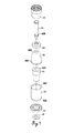
- FIG. 7 is an exploded perspective view of the piston chamber assembly.
- FIG. 8 a is a cross sectional view of Applicant's piston chamber assembly apart from the rest of the metered fill valve.
- FIG. 8 b is an exploded cross sectional view of the reset plunger meter pin assembly.
- FIGS. 9 a and 9 b are exterior side elevational and cross sectional views of the piston sleeve.
- FIGS. 10 a and 10 b are top elevational and side cross sectional views of the inner housing upper member.
- FIGS. 11 a and 11 b are top elevational and side cross sectional views of intermediate housing cap.
- FIGS. 12 a and 12 b are side elevational and cross sectional views of intermediate housing.
- FIGS. 13 a and 13 b are side elevational and cross sectional views of inner housing lower member.
- FIGS. 14 a and 14 b are side, upper perspective, and side cross sectional views of inlet channel member.
- FIGS. 15 a and 15 b are side, upper perspective, and side cross sectional views of lower housing section.
- FIGS. 16 a and 16 b are side, upper perspective, and side cross sectional views of upper housing section.
- FIG. 17 a illustrates prior art side elevational cutaway view of fluid flow through a main fluid flow pathway.
- FIG. 17 b is a side elevational cutaway view of fluid flow and pressure (arrows) against Applicant's biasing member.
- FIG. 18 illustrates a partial, side elevational cross-sectional view, of an alternate embodiment of a piston chamber using a seal instead of a diaphragm.
- FIG. 19 illustrates a side elevational, cross-section of the valve assembly with an alternate embodiment of a biasing member.
- FIGS. 1-4 illustrate a metered fill valve assembly (sometimes “valve assembly”) 10 including lever 56 used in the holding tank of a commode.
- a flush handle FH mounted on the tank is seen to engage and actuate a flush lever FL mounted in the tank, and also lever 56 .
- Applicant's metered fill valve assembly may adjust the flow of the water from a pressurized water source PWS such as a water supply line. In metering the flow from PWS to the holding tank, with the use of Applicant's novel metering fill valve, water volume from the pressurized water source PWS to the tank may be accurately controlled.
- Applicant may adjust valve assembly 10 to provide for a small amount of water in the holding tank or a large amount of water in the holding tank or selectively set the amount of water in the holding tank between these extremes.
- the metering of the water flow between PWS and the tank is selectively set by the user for a desired tank volume.
- the metering of the flow between an ON and OFF position uses the actual pressure of the PWS along with a biasing member 44 to control the time that it takes to fill a metered diaphragm or piston cavity PC volume, which is then used to control the flow of water into the tank.
- valve assembly 10 dispenses water or other fluid under pressure in a manner that can control the volume of fluid expelled from valve assembly 10 .
- volume of liquid can be controlled by simple adjustment of the valve assembly.
- FIG. 6 a may be referred to as the “ready state.”
- the commode bowl has been filled, it can be seen that there is no flow of fluid through the valve, no flow of fluid into a metered flow or piston chamber PC (that is to say, no metered flow MTF), and no flow past main seal 46 (that is to say, no main flow MNF).
- the parts of valve assembly 10 are not moving.
- Reset outlet/metered pin seal 54 prevents the pressurized fluid in piston chamber PC from escaping therefrom.
- fluid pressure on piston cap 38 urges piston diaphragm assembly 22 (see FIG. 8 a ) down, thus urging main seal 46 against lower main seal seat 18 a of inlet channel member 18 .
- the area of piston cap 38 and exposed area of the piston core 40 is greater than the exposed area of the seal 46 and the lower end of piston core 40 and, the pressure trying to unseat seal 46 being the same as the pressure pushing down, the net effect will be for the pressurized water source PWS to maintain the seal of (that is, preventing) the main flow MNF as illustrated in FIG. 6 a.
- FIG. 6 a provides for the valve in a ready-to-flush position with no fluid flowing therethrough at all. The instant the lever 56 is raised and, therefore, plunger 50 urged downward, seal 54 is broken and there is a rapid emptying of the piston chamber with the resultant movement of the piston diaphragm assembly upward to the position seen in FIG. 6 c.
- FIG. 6 d the main filling position of the valve, it will be seen that there are two types of flow pathways into the valve and one flow pathway out of the valve.
- FIG. 6 d illustrates the valve in the position where it is actively filling a container, such as the holding tank and bowl of a toilet. Further, it can be seen in FIG. 6 d that metering flow MTF is occurring in channel 40 a and into metered flow or piston chamber PC. However, since seal 54 is sealing the piston chamber (plunger 50 having been released) that, as the piston chamber PC fills with metering flow, piston diaphragm assembly 22 and the piston are moving downward as shown by the arrows, and main seal 46 is approaching lower main seal seat 18 a .
- main fluid flow MNF
- flap 44 a of biasing member 44 is lifted, by fluid pressure, slightly off outer surface 42 a of piston sleeve 42 .
- main fluid flow MNF it is seen that there is nowhere for the flow to go except through holes 26 a along the lower edge of inner housing lower member 26 and up the annulus created between inner housing lower member 26 and intermediate housing 30 . Moving up through the annulus, there is nowhere else to go except through openings or slots 30 a of the upper perimeter of intermediate housing 30 .
- FIG. 6 d illustrates another view of main flow MNF moving up channel 18 c of inlet channel member 18 . Fluid flow is seen passing through bays 16 b (see also FIG.
- valve assembly 10 may leave valve assembly 10 through bowl refill outlet 15 , which may be connected to an overflow pipe in the tank to help refill the toilet bowl.
- a piston chamber assembly 20 includes a piston diaphragm assembly 22 , inner housing lower member 26 , inner housing upper member 24 , and biasing member 44 .
- Piston diaphragm assembly 22 includes piston cap 38 , piston sleeve 42 , piston core 40 , seal 46 , and diaphragm 36 .
- Inner housing upper member 24 is seen to engage inner housing lower member 26 , which in turn engages biasing member 44 to provide a chamber that will serve several functions.
- the large chamber defined by the foregoing elements 24 / 26 / 44 is seen to provide a chamber in which piston diaphragm assembly 22 can move up and down as illustrated in FIG. 8 a , and as explained with reference to FIGS. 6 a - 6 d .
- the piston chamber PC is almost empty and the metering cycle, which is shown at the very beginning in FIG. 6 c and at a mid-point in FIG. 6 d , can begin.
- a reset plunger meter pin assembly 28 to initiate the MNF and meter the MTF and the movement of the piston diaphragm assembly 22 for shutting off the main flow MNF after a metered amount of water has filled the piston chamber PC and seated seal 46 of seat 18 a.
- FIGS. 3 , 6 d , 8 a , 10 a , and 10 b show how intermediate housing cap 36 lies between upper housing section 14 (above) and inner housing upper member 24 (below).
- This structure is designed to achieve a number of functions, including providing a path for metered fluid in piston chamber PC to empty from the piston chamber PC and out as set forth above with reference to FIG. 6 b .
- Inner housing upper member 24 includes: reset plunger seal seat 24 a ; outer uprights 24 b ; inner uprights 24 c ; channels 24 d ; and bays 24 e .
- Outer and inner uprights 24 b / 24 c are seen in FIG. 6 a . These provide a seat for vacuum breaker disc 33 as seen in FIG. 6 a .
- the underside of intermediate housing cap 32 is urged downward by engagement with the upper housing section 14 , downward meaning urged against the upper perimeter or edge of intermediate housing 30 c .
- Channels 24 d are created between bays 24 e and adjacent inner and outer uprights to expel metering fluid as set forth above into the annulus and downward between intermediate housing 30 and upper housing section 14 (see FIG. 6 b ).
- inner housing upper member 24 is seen to have a recess 24 f therein for receiving spring 52 therein (see FIG. 6 d ).
- Inner housing upper member 24 is further seen to have a cylindrical thin-sided skirt 24 g extending downward therefrom for sandwiching diaphragm 36 against the inner wall of inner housing lower member 26 as seen in FIG. 8 a .
- This skirt 24 g helps prevent diaphragm 36 from wrinkling or otherwise deforming during movement of the piston diaphragm assembly 20 .
- diaphragm 36 has an outer bead 36 a for receipt into upper recess 26 b in inner housing lower member 26 .
- Diaphragm 36 is usually made with an elastomeric flexible rubber, rubber-like material or other suitable material. Bead 36 a helps provide a fluid tight seal especially when the underside of inner housing upper member 24 sits against the bead as seen in FIG. 8 a.
- Piston diaphragm assembly 22 may include a piston 34 , which may be comprised of piston core 40 received tightly within a piston sleeve 42 to which is tightly fitted a piston cap 38 .
- Piston core 40 is seen to have metering channel 40 a therein for carrying metering fluid from the pressurized water source PWS, here typically connected to the lower end of inlet channel member 18 .
- piston diaphragm assembly 22 is seen here to be comprised of separate members, it is possible to make them from a single member or several members with the diaphragm separate from the unitary elements 34 / 36 / 38 / 40 / 46 or any number of other structures to serve the same functions.
- FIG. 8 a also illustrates notch 40 b for carrying main seal 46 therein, such that main seal 46 moves with and may be seen to be part of piston diaphragm assembly 22 .
- Plunger 50 is seen to include an inner threaded section 50 a for threadable receipt of the meter pin 48 therein.
- Meter pin 48 has a threaded section 48 a that is designed to threadably engage threaded section 50 a of plunger 50 .
- Metering pin 48 may also have, at a near end thereof, adjusting tool receiving cutout 48 b for receiving a tool so that pin 48 may be rotated with respect to plunger 50 . Manual adjustment will cause pin 48 to move axially along reset plunger 50 .
- Plunger 50 may have a lever receiving cutout 50 b near the upper end thereof for receipt of a lever 56 as seen in FIG. 3 .
- Spring shoulder 50 c may also be provided near a removed end of plunger 50 for receipt of spring 52 there into.
- Metering pin 48 is also seen to have an elongated or lower portion 48 c as seen in FIG. 8 b , and also as seen in the “Series 6” figures, for example, FIG. 6 a , which lower portion 48 c typically extends at least partially into channel 40 a of piston diaphragm assembly 22 . In such a position, lower portion will restrict the flow of fluid in channel 40 a as it is urged towards piston chamber PC. Typically, a gap of 1 to 10 mil (that is, 1 thousandth to 10 thousands of an inch), for example, between the walls of channel 40 a and lower portion 48 c may be provided. During fabrication, this may be adjusted according to need. The distance lower portion 48 c extends into channel 40 a is adjustable.
- moving downward or moving upward metering pin 48 will alter the extent to which lower portion 48 c extends into channel 40 a .
- the less the metering pin 48 extends into the channel 40 a the faster the piston chamber will fill and the quicker it will cause seal 46 to shut off main flow MNF.
- extending metering pin 48 far into channel 40 a will provide a slower filling and a longer period of time that the main seal 46 remains unseated, and therefore will provide more fluid entering whatever container is being filled, be it a commode, tank or any other container.
- plunger 50 is seen to include a seal receiving cutout 50 d dimensioned to receive tightly thereon skirt 54 a of reset outlet/meter pin seal 54 .
- reset outlet/meter pin seal 54 sits tightly in cutout 50 d against the removed end of plunger 50 , so that as plunger 50 moves downward in response to moving the lever or handle of a commode, seal 54 will unseat and open the piston chamber as seen in FIG. 6 b .
- Reset outlet/meter pin seal 54 also has a pin seal portion 54 c , which rides against meter pin 48 when the meter pin is being adjusted up or down, but is sufficient to prevent fluid under pressure in the piston chamber PC from finding its way up and out between the inner channel of the plunger 50 and the metering pin 48 .
- reset outlet/meter pin seal 54 prevents fluid from leaking out past the metering pin 48 and out the inner bore of plunger 50 .
- piston cap 38 is dimensioned to slide over diaphragm inner skirt 36 b to wedge or jam and seal skirt 36 b against an upper surface 42 a of piston sleeve 42 as can be seen, also, in FIG. 8 a . It is also seen with reference to FIGS. 7 and 8 a how bead 36 a of diaphragm 36 sits in upper recess 26 b . Other suitable methods of sealing the diaphragm 36 may be used.
- FIGS. 11 a , 11 b , 12 a , and 12 b these are seen to illustrate structure of intermediate housing 30 and intermediate housing cap 32 .
- the position of these two elements with respect to one another and with respect to the upper housing section 14 and the piston chamber assembly 20 may be further appreciated with respect to the “Series 6 ” figures. It is seen, for example, that slots 30 a are provided for the flow of the metering fluid MTF out through hole 24 h across through channels 24 d , the top of inner housing upper member 24 , and out the slots 30 a . It is also seen how removed end 30 b seats snugly on upper end 18 h of inlet channel member 18 (see Detail A, FIG. 6 d ).
- Intermediate housing cap 32 is seen to include recess 32 a on an underside thereof for loose receipt of vacuum breaker disc 33 thereonto.
- Vent holes 32 b are provided for venting if there is need for a vacuum break as set forth in more detail below.
- Seal cutout 32 c is provided for receipt of plunger seal 51 thereinto as seen, for example, in FIG. 6 a .
- Hole 32 d is dimensioned for slideable engagement with plunger 50 therethrough as seen in FIG. 6 a.
- FIGS. 13 a and 13 b further details of inner housing lower member 26 may be seen, including the structure and location of holes 26 a , upper recess 26 b , and lower cutout 26 c . Functional details of the operation of these elements in flow control may be seen with reference to other sections of these specifications.
- lower inlet channel member 18 may be provided.
- Upper end 18 h is dimensioned to slideably engage, couple with, and positionally locate intermediate housing 30 (see Detail A, FIG. 6 d ) .
- Threaded removed end 18 b may be provided for threadably coupling a fitting on a support structure, such as a holding tank and/or threadably fitting a high pressure water hose line or other PWS.
- Channel 18 c is provided to carry the main fluid flow MNF up past the lower main seal seat 18 a and biasing member 44 as seen in FIG. 6 d .
- the inner surface near the upper end 18 c of channel is seen to be segmented into a series of lands 18 d separated by bays 18 e (see FIG. 6 e ).
- Lands 18 d will engage the outer rim 46 a of main seal 46 to stabilize it and the piston to which it is attached as it slides up and down as seen in “Series 6 ” figures.
- Bays 18 e provide channeling for the water upward while lands 18 d provide a surface across which main seal 46 can slide.
- Lip 18 f will abut the top of legs 16 a of lower housing section 16 (see FIG. 15 a , and FIGS. 6 d and 6 e ), while upper end 18 h is slideably received into removed end 30 b of housing 30 to help stabilize the assembly.
- shoulder 18 g engages bays legs 16 a , so as to provide main fluid flow MNF through the bays or channels 16 b and out the annulus between inlet channel member 18 and lower housing section 16 as seen in FIG. 6 d , Detail B and FIG. 6 e .
- Locking members 16 c of lower housing section 16 are seen to engage upper housing section grooves 14 a for receipt of locking members 16 c thereinto as seen in FIG. 6 d .
- Upper housing section 14 is also seen to be vented through vent holes 14 b at a near or upper end thereof as seen in FIG. 6 d . It is seen with reference to FIG. 6 d , for example, how elements 14 and 16 couple to one another so as to “sandwich” the upper end of element 18 against the lower ends of elements 30 and 26 but in a manner that allows water to flow down the annulus inside the coupled 14 and 16 .
- Both grooves 14 a and vent holes 14 b may also be seen with preference to FIGS. 16 a and 16 b .
- These figures show further details of upper housing section 14 including a lever housing 14 c for receipt of lever end 56 a thereinto as seen in FIG. 3 .
- Lever housing 14 c may also have pin channel 14 d therethrough for receipt of pin 58 therethrough to pivotally hold lever end 56 a in the lever housing 14 c .
- Bore 14 e is dimensioned to slideably receive plunger 50 (see FIG. 6 d ).
- An inlet screen 60 may be seated at the base or removed and of in the inlet channel member 18 as seen in FIG. 6 c .
- Operation and construction considerations of the metered fill valve biasing member 44 may be understood with reference to the following. Pressure range and response of the metered fill valve 10 are enhanced by the action of biasing member 44 . Enhanced is defined as generally consistent operation at a lower pressure limit of PWS and accurate, repeatable volume metering at any pressure that may typically be found in a PWS.
- Biasing member 44 may consist of three parts: flap 44 a , base 44 c and leg 44 b .
- the function of the annular leg 44 b is to help center biasing member 44 in relation to the inner housing lower member 26 (see FIG. 6 d , Detail A). It may or may not form a seal between the inner housing lower member 26 and the removed end 30 b of the intermediate housing 30 .
- Base 44 c helps create a receiving area for upper end 18 h and a stop or upper limit seat for the main seal 46 to limit the piston diaphragm assembly's 22 upward travel (see FIG. 6 c ). Flap 44 a restricts the flow MNF of water past the piston sleeve 42 creating a higher pressure zone on bottom or upstream side of biasing member 44 (see Detail A, FIG. 6 d ).
- Biasing member 44 may be made from any suitable material, typically flexible, such as Sanoprene.® In construction of the biasing member 44 , the stiffness of the material used as well as the angle of the flap of biasing member with respect to the outer side wall of the piston are among two of the variables that may be adjusted.
- biasing member 44 its placement with respect to the outer wall of the piston may also be considered.
- the removed end of flap 44 a would be just touching the piston side wall when the valve assembly 10 is constructed.
- metered flow would occur, however, only with flow also occurring in the metered channel.
- the removed end of the flap may be a few mil either way, during construction of the valve. That is to say, the removed end of flap 44 a may be set a few mil off or a few mil bent against (partial bias) the outer side wall.
- bias pressure is too high, either as a result of a stiff construction of the bias member itself, or too much pressure as set against the outer wall of the piston, or too great an angle, then operation of the valve may not occur at a low pressure insufficient to open an annulus past the biasing member. If the bias member flap is too far away from the wall of the piston, even without any bending, leaks may occur of water through the main water flow pathway, which leaks will occur without enough back pressure to generate metered flow in a timely fashion.
- prioritizing metered flow such as is illustrated here means that structure may generate metered flow with or without sufficient pressure in the PWS to generate main fluid flow through the main fluid flow pathway.
- biasing member 44 or other suitable structure that closes down or reduces the area of a main fluid flow pathway responsive to a drop in upstream pressure water source pressure. At no pressure in the pressure water plus a small amount of water pressure in the pressure water source, the metering then may received metered water flow even without any main fluid flow. This is a result of bias member 44 responding to a drop in pressure.
- Reference to FIG. 17 a illustrates an example of flow through prior art, “static” main fluid flow pathways. It will be seen with reference to FIG.
- the biasing member responds by a greater degree of occluding the main fluid flow pathway and providing a greater pressure for metering water to flow up the metering channel than there would be without the greater degree of occluding.
- This higher pressure zone generated by the action of biasing member 44 is especially useful if the pressurized water source PWS pressure is lower than about 30 PSI and typically is necessary if the PWS is below about 15 PSI, as it ensures a predictable, positive source of water for the MTF water flow thru the metering channel 40 a and into the piston chamber PC.
- This higher pressure zone also acts in an “upward direction” on the bottom area of the piston core 40 and bottom area of seal 46 opposing the downward pressure acting on the top of the piston cap 38 and related elements.
- the ratio of exposed upper area of the piston diaphragm assembly 22 pushing down (as seen, for example, in FIG. 6 d ) on the piston to the smaller exposed area generating upward motion on the piston may be approximately 2 to 1. This ratio may be altered as necessary for other situations or desired results.
- biasing member 44 is seen to be easily replaceable if other configurations are desired.
- the area of the piston sleeve 42 and the pressure created by biasing member 44 also urge the upward movement of the piston diaphragm assembly 22 when pressing the reset plunger 50 relieves the opposing pressure on the top of the piston cap 38 .
- flap 44 a is forced further away from the piston sleeve 42 , creating a larger annulus area for the MNF path (see Detail A, FIG. 6 d ).
- the amount the flap 44 a moves and the subsequent increase in MNF path annulus are determined, in part, by the durometer of the elastomer (or other suitable material) of which the biasing member 44 may be constructed of and the thickness and height of flap 44 a .
- flap 44 a creates more back pressure in the high pressure zone and a more flexible flap 44 a creates less back pressure.
- An elastomer durometer on the Shore A scale of 70 with flap 44 a width of about 0.063 inch and flap 44 a height of about 0.185 in. produces satisfactory operation at PWS pressures of about 1/4 psi to 160 or more psi.
- the resistance to flex of flat 44 a increases, non-linearly, with respect to deflection pressure such that an increase in pressure of the deflection force of the water generates, non-linearly, a greater back pressure.
- FIG. 18 illustrates that in place of a diaphragm 36 , a seal 37 may be used. Seal 37 will seal between the piston and the inner side walls of inner housing lower member 26 as illustrated. FIG. 18 also illustrates that a gasket 27 may be used between the upper perimeter of element 26 and inner housing upper member 24 to ensure a fluid tight piston chamber when seal 37 is used. Moreover, in the claims, when the words “diaphragm assembly,” “piston diaphragm assembly” or the like are used, it means that a diaphragm 36 , a seal 37 or any other suitable member is intended within that term, which suitable member will allow for functional equivalent of elements 36 / 37 .
- Biasing member may also be configured as a male element or any other suitable structure.
- FIG. 19 shows an alternate preferred embodiment of biasing member 44 .
- biasing member 44 is shown not only to be in a different configuration itself, but also at a different location in the main fluid flow channel.
- flap 44 a is not angled with respect to the side walls of inlet channel member 18 , but instead is oriented about perpendicular to these walls (that is, not bent but straight). Moreover, it may, in an unpressurized situation, just touch the side walls or indeed maybe slightly against or slightly away from the side walls.
- occlusion is a function of pressure, such that a pressure drop against the biasing member will cause a greater degree of occlusion of the main fluid flow pathway or a complete occlusion thereof.
- a metering flow mechanism may be on the side of housing or any other suitable location.
- the terms “upper” and “lower” main seal seat are used herein to describe any structure on the valve assembly 10 engaging the piston seal 46 so as to substantially prevent a flow of non-metered water through valve assembly 10 .
- water refers to any fluid.
Landscapes
- Physics & Mathematics (AREA)
- General Physics & Mathematics (AREA)
- Engineering & Computer Science (AREA)
- Automation & Control Theory (AREA)
- Sanitary Device For Flush Toilet (AREA)
- Fluid-Driven Valves (AREA)
Abstract
Description
Claims (22)
Priority Applications (1)
| Application Number | Priority Date | Filing Date | Title |
|---|---|---|---|
| US13/100,716 US8827237B2 (en) | 2010-05-05 | 2011-05-04 | Metered fill valve |
Applications Claiming Priority (2)
| Application Number | Priority Date | Filing Date | Title |
|---|---|---|---|
| US33165610P | 2010-05-05 | 2010-05-05 | |
| US13/100,716 US8827237B2 (en) | 2010-05-05 | 2011-05-04 | Metered fill valve |
Publications (2)
| Publication Number | Publication Date |
|---|---|
| US20110272037A1 US20110272037A1 (en) | 2011-11-10 |
| US8827237B2 true US8827237B2 (en) | 2014-09-09 |
Family
ID=44901133
Family Applications (1)
| Application Number | Title | Priority Date | Filing Date |
|---|---|---|---|
| US13/100,716 Expired - Fee Related US8827237B2 (en) | 2010-05-05 | 2011-05-04 | Metered fill valve |
Country Status (2)
| Country | Link |
|---|---|
| US (1) | US8827237B2 (en) |
| WO (1) | WO2011140210A1 (en) |
Citations (5)
| Publication number | Priority date | Publication date | Assignee | Title |
|---|---|---|---|---|
| US4662602A (en) | 1985-10-28 | 1987-05-05 | Masco Corporation | Metering valve |
| USRE32880E (en) | 1985-10-15 | 1989-02-28 | The Laitram Corporation | Rolling diaphragm metering valve |
| US4843657A (en) | 1987-09-17 | 1989-07-04 | Orr James W | Anti-flood toilet tank fill valve |
| US7171702B2 (en) | 2003-10-01 | 2007-02-06 | H2O Guard, Inc. | Toilet tank fill valve and method of operation |
| US7661438B2 (en) | 2006-09-28 | 2010-02-16 | David Nichols-Roy | Water saver fill valve and assembly |
Family Cites Families (5)
| Publication number | Priority date | Publication date | Assignee | Title |
|---|---|---|---|---|
| US3074684A (en) * | 1957-10-25 | 1963-01-22 | Orville K Doyle | Valve with positive shutoff |
| US3842857A (en) * | 1973-04-06 | 1974-10-22 | R Mccornack | Metering valve construction |
| US5134729A (en) * | 1989-01-18 | 1992-08-04 | Shaw William S | Universal positive shut off, metered water control system for use with flush toilet tanks |
| US5655748A (en) * | 1996-01-02 | 1997-08-12 | T&S Brass And Bronze, Inc. | Metering valve |
| US6550744B2 (en) * | 2001-07-02 | 2003-04-22 | Sloan Valve Company | Relief valve head for piston-style flush valve |
-
2011
- 2011-05-04 US US13/100,716 patent/US8827237B2/en not_active Expired - Fee Related
- 2011-05-04 WO PCT/US2011/035178 patent/WO2011140210A1/en active Application Filing
Patent Citations (5)
| Publication number | Priority date | Publication date | Assignee | Title |
|---|---|---|---|---|
| USRE32880E (en) | 1985-10-15 | 1989-02-28 | The Laitram Corporation | Rolling diaphragm metering valve |
| US4662602A (en) | 1985-10-28 | 1987-05-05 | Masco Corporation | Metering valve |
| US4843657A (en) | 1987-09-17 | 1989-07-04 | Orr James W | Anti-flood toilet tank fill valve |
| US7171702B2 (en) | 2003-10-01 | 2007-02-06 | H2O Guard, Inc. | Toilet tank fill valve and method of operation |
| US7661438B2 (en) | 2006-09-28 | 2010-02-16 | David Nichols-Roy | Water saver fill valve and assembly |
Also Published As
| Publication number | Publication date |
|---|---|
| WO2011140210A1 (en) | 2011-11-10 |
| US20110272037A1 (en) | 2011-11-10 |
Similar Documents
| Publication | Publication Date | Title |
|---|---|---|
| US7140590B2 (en) | Pinch valve element for plumbing fixture flush valve | |
| AU2009202437B2 (en) | Two-stroke foam pump | |
| US5026021A (en) | Flush control assembly for pressure flush valves | |
| US5241711A (en) | Pressurized toilet flushing assembly | |
| EP1548344A1 (en) | Opening and closing valve | |
| KR20080111457A (en) | Dual flush activation | |
| US4230145A (en) | Fluid control valve | |
| US9730538B2 (en) | Surface tension condiment dispenser | |
| EP0353096B1 (en) | Self-closing valve assembly | |
| US20100287692A1 (en) | Water conserving toilet | |
| US9816636B2 (en) | Rigid piston retrofit for a diaphragm flush valve | |
| US8827237B2 (en) | Metered fill valve | |
| JP2006266276A (en) | Self-closing valve | |
| JP3595728B2 (en) | Drain discharge device | |
| GB2453439A (en) | Flushing valve | |
| US20050161625A1 (en) | Adjustable metering actuator assembly for a water closet | |
| EP2864555B1 (en) | Rigid piston retrofit for diaphragm flush valve | |
| US11365534B2 (en) | Hydraulic system including manifold, flush valve, and shut off | |
| US20230243137A1 (en) | Flush Valve Apparatus | |
| GB2255424A (en) | Fluid flow control valves | |
| JP2004251422A (en) | Pilot type self closing valve | |
| AU2011203210A1 (en) | Dual flush activation | |
| AU7499300A (en) | Liquid flow control valve |
Legal Events
| Date | Code | Title | Description |
|---|---|---|---|
| AS | Assignment |
Owner name: BAKER PRODUCTS, LTD., TEXAS Free format text: ASSIGNMENT OF ASSIGNORS INTEREST;ASSIGNOR:DULIN, ROBERT;REEL/FRAME:026277/0648 Effective date: 20110509 |
|
| AS | Assignment |
Owner name: BAKER PRODUCTS, LTD, TEXAS Free format text: CORRECTIVE ASSIGNMENT TO CORRECT THE TYPE OF ENTITY OF ASSIGNEE PREVIOUSLY RECORDED ON REEL 026277 FRAME 0648. ASSIGNOR(S) HEREBY CONFIRMS THE ASSIGNMENT;ASSIGNOR:DULIN, ROBERT;REEL/FRAME:026478/0264 Effective date: 20110509 |
|
| STCF | Information on status: patent grant |
Free format text: PATENTED CASE |
|
| FEPP | Fee payment procedure |
Free format text: MAINTENANCE FEE REMINDER MAILED (ORIGINAL EVENT CODE: REM.) |
|
| FEPP | Fee payment procedure |
Free format text: SURCHARGE FOR LATE PAYMENT, SMALL ENTITY (ORIGINAL EVENT CODE: M2554) |
|
| MAFP | Maintenance fee payment |
Free format text: PAYMENT OF MAINTENANCE FEE, 4TH YR, SMALL ENTITY (ORIGINAL EVENT CODE: M2551) Year of fee payment: 4 |
|
| FEPP | Fee payment procedure |
Free format text: MAINTENANCE FEE REMINDER MAILED (ORIGINAL EVENT CODE: REM.); ENTITY STATUS OF PATENT OWNER: SMALL ENTITY |
|
| LAPS | Lapse for failure to pay maintenance fees |
Free format text: PATENT EXPIRED FOR FAILURE TO PAY MAINTENANCE FEES (ORIGINAL EVENT CODE: EXP.); ENTITY STATUS OF PATENT OWNER: SMALL ENTITY |
|
| STCH | Information on status: patent discontinuation |
Free format text: PATENT EXPIRED DUE TO NONPAYMENT OF MAINTENANCE FEES UNDER 37 CFR 1.362 |
|
| FP | Lapsed due to failure to pay maintenance fee |
Effective date: 20220909 |