US8828126B2 - Removable final scrubber tube - Google Patents
Removable final scrubber tube Download PDFInfo
- Publication number
- US8828126B2 US8828126B2 US13/357,894 US201213357894A US8828126B2 US 8828126 B2 US8828126 B2 US 8828126B2 US 201213357894 A US201213357894 A US 201213357894A US 8828126 B2 US8828126 B2 US 8828126B2
- Authority
- US
- United States
- Prior art keywords
- housing
- manifold
- input
- valves
- fittings
- Prior art date
- Legal status (The legal status is an assumption and is not a legal conclusion. Google has not performed a legal analysis and makes no representation as to the accuracy of the status listed.)
- Active, expires
Links
Images


Classifications
-
- G—PHYSICS
- G01—MEASURING; TESTING
- G01N—INVESTIGATING OR ANALYSING MATERIALS BY DETERMINING THEIR CHEMICAL OR PHYSICAL PROPERTIES
- G01N1/00—Sampling; Preparing specimens for investigation
- G01N1/28—Preparing specimens for investigation including physical details of (bio-)chemical methods covered elsewhere, e.g. G01N33/50, C12Q
- G01N1/40—Concentrating samples
- G01N1/4022—Concentrating samples by thermal techniques; Phase changes
-
- G—PHYSICS
- G01—MEASURING; TESTING
- G01N—INVESTIGATING OR ANALYSING MATERIALS BY DETERMINING THEIR CHEMICAL OR PHYSICAL PROPERTIES
- G01N1/00—Sampling; Preparing specimens for investigation
- G01N1/28—Preparing specimens for investigation including physical details of (bio-)chemical methods covered elsewhere, e.g. G01N33/50, C12Q
- G01N1/40—Concentrating samples
- G01N1/4055—Concentrating samples by solubility techniques
- G01N2001/4066—Concentrating samples by solubility techniques using difference of solubility between liquid and gas, e.g. bubbling, scrubbing or sparging
-
- Y—GENERAL TAGGING OF NEW TECHNOLOGICAL DEVELOPMENTS; GENERAL TAGGING OF CROSS-SECTIONAL TECHNOLOGIES SPANNING OVER SEVERAL SECTIONS OF THE IPC; TECHNICAL SUBJECTS COVERED BY FORMER USPC CROSS-REFERENCE ART COLLECTIONS [XRACs] AND DIGESTS
- Y10—TECHNICAL SUBJECTS COVERED BY FORMER USPC
- Y10T—TECHNICAL SUBJECTS COVERED BY FORMER US CLASSIFICATION
- Y10T29/00—Metal working
- Y10T29/53—Means to assemble or disassemble
Definitions
- the present invention relates to inert gas fusion analyzers and particularly to an improved system for the replacement of the final scrubber for the inert carrier gas.
- an inert gas such as helium
- the carrier gas must be substantially free of contaminates and impurities which would interfere with accurate detection of the desired elements.
- oxygen or moisture for example, must be removed from the carrier gas stream before it enters the furnace. Contaminates are removed by a finish or final scrubber in the carrier gas stream which is typically located in close proximity to the carrier gas inlet to the combustion furnace.
- a system for changing a filter element in an analyzer includes a fluid flow path includes a manifold with input and output fluid fittings and at least one valve coupled to one of the input and output fittings.
- a housing for a filter element includes fluid fittings which align with and couple to associated ones of input and output fluid fittings of the manifold.
- the housing includes a valve controlling actuator, such that, when the housing is removed from the manifold for the replacement of a filter mounted to the housing, the valve shuts off the flow path to the input and output fittings.
- the housing includes mechanical valves which seal the housing when removed from the manifold.
- the system of the present invention thus, includes a manifold with valves for selectively bypassing a quick disconnect final scrubber housing that includes a filter tube and sealed gas fittings.
- the housing includes alignment members and a latch for positioning and locking the housing onto and in sealed engagement with the instrument's manifold.
- a switch detects the presence of the housing, and a control circuit controls valves to direct the inert gas flow either though the filter tube or bypass the filter tube when the housing is removed.
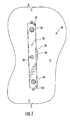
- FIG. 1 is a fragmentary front elevation view of an analyzer showing the front of a manifold for receiving a removable final scrubber housing;
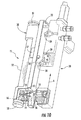
- FIG. 2 is a front elevation view as seen in FIG. 1 shown with the final scrubber mounted in place;
- FIG. 3 is a front perspective view of the housing and filter tube of the final scrubber
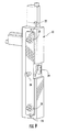
- FIG. 4 is a rear elevation view of the housing shown in FIG. 3 , with the latch in a latched position;
- FIG. 5 is a rear elevation view of the housing shown in FIG. 4 , with the latch in an unlatched position;
- FIG. 6 is a perspective view illustrating the mounting and removal of the housing from the manifold
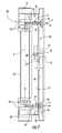
- FIG. 7 is a vertical cross-sectional view of the manifold and housing assembly engaged for the use of the final scrubber
- FIGS. 7A-7D are perspective sequential views of the mounting of one of the end caps to the housing
- FIG. 8 is a rear perspective view of the manifold seen in FIGS. 1 and 7 ;
- FIG. 9 is a front perspective view of the manifold seen in FIG. 8 ;
- FIG. 10 is a right side perspective view, partly in cross section and partly exploded, of the housing and manifold of the present invention.
- FIG. 11 is a right side perspective view, partly in cross section and partly exploded, of the housing and manifold of the present invention.
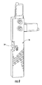
- FIG. 12 is an enlarged fragmentary perspective cross-sectional view of the gas connection at the lower end of the housing and manifold.
- FIGS. 13A and 13B are a flow diagram of an analytical instrument embodying the present invention.
- an instrument 10 for the analysis of elements such as nitrogen, oxygen, hydrogen, or the like, utilizing an electrode resistance furnace.
- the instrument 10 can be a Model TCH-600, commercially available from Leco Corporation of St. Joseph, Mich.
- Instrument 10 includes an electrode furnace 11 ( FIG. 13B ) employing carbon crucibles holding a sample to be fused or heated.
- the resultant gases are analyzed in a conventional manner utilizing an inert carrier gas, such as helium, with a flow path for the instrument as illustrated in FIGS. 13A and 13B .
- an inert carrier gas such as helium
- the helium used is typically a high quality laboratory grade, it still may contain some oxygen and moisture which interferes with the accurate analysis of the sample.
- the instrument 10 includes a final or finish scrubber 15 ( FIGS. 2 and 13B ), which is located closely adjacent the input to the furnace and in the carrier gas flow path.
- these scrubbers also known as OMI (oxygen moisture indicator)
- OMI oxygen moisture indicator
- these scrubbers have been mounted to the instrument by threaded fittings which require tools for the removal and replacement of the final scrubber, as well as significant down time for the instrument.
- the flow of carrier gas is forced to bypass the furnace during the replacement period of time, which can disrupt the purged gas pathway.
- the system of the present invention provides a manifold assembly 20 mounted on the front wall 12 of the instrument, as illustrated in FIG. 1 , for removably receiving the housing assembly 30 of the final scrubber 15 , as illustrated in FIGS. 2 , 6 , 10 , and 11 .
- the housing 30 includes a filter cartridge 32 , such as available from the Sigma-Aldrich Company, Model Supelco 2-3906, which is a lithium-based reagent for removing oxygen and moisture from a carrier gas stream.
- the cartridge is held within the housing by an upper and lower end caps 31 and 33 , respectively, which allow the easy and fast replacement of the cartridge 32 once housing 30 is removed from the manifold 20 of instrument 10 .
- the user of the instrument 10 may have a backup housing 30 with a new cartridge 32 to facilitate the quick replacement of the final scrubber or may remove the housing 30 , replace the filter cartridge 32 while it is removed, and then reconnect the housing 30 to the manifold 20 (as illustrated in FIG. 6 ).
- the housing and manifold cooperate with one another to provide both a locked mechanical connection as well as a sealed gas stream connection.
- the manifold 20 includes input and output three-way valves 52 and 54 ( FIGS. 13A and 13B ), which automatically bypass the final scrubber 15 when removed from the manifold, as seen in FIGS. 1 , 3 and 6 .
- the system provides a bypass flow path 56 for the inert gas stream which can continue to flow through the furnace keeping it purged of any contamination.
- the three-way valves 52 , 54 also can be actuated to allow segmented leak detection of the gas flow path in the instrument.
- the manifold 20 includes a pair of alignment pins 22 and 23 extending outwardly at the upper and lower corners, as seen in FIG. 1 . These pins mate with corresponding apertures 41 and 43 ( FIGS. 4 and 5 ) extending through the back plate 40 of final scrubber housing 30 . These pins 22 and 23 also act to prevent the user from placing the housing 30 onto the manifold 20 without first securing the end caps 33 into the proper position as described below.
- the end caps 31 , 33 of the housing 30 are used to pierce the foil seals of the final scrubber cartridge 32 and include O-ring seals 44 to provide a sealed connection to cartridge 32 .
- the end caps 31 and 33 also have lock pins 39 that lock the end caps in place on the housing 30 ( FIGS. 7A-7D ).
- pin 39 enters slot 47 ( FIG. 7C ).
- the user then rotates the end caps 31 , 33 to engage under a lip 49 adjacent slot 47 as seen in FIG. 7D to lock caps 31 , 33 in place. If the lock pins 39 are not properly rotated and engaged, they will encounter the matching alignment pins 22 or 23 on the manifold 20 ( FIG.
- This feature is designed to ensure that the final scrubber cartridge 32 is not placed on the manifold 20 without the lock pins 39 and end caps 31 , 33 properly sealably engaged. This feature also prevents the sensor switch 29 from becoming activated, pressurizing the final scrubber cartridge 32 causing the end caps 31 , 33 to inadvertently pop off if not properly secured.
- the housing 30 also includes spring-loaded valves 17 and 19 ( FIG. 7 ) which seal the cartridge 32 when removed from manifold 20 . This prevents contamination from entering the cartridge 32 prior to installation of the final scrubber 15 to the instrument.
- the projecting gas fittings 24 and 26 mechanically actuate the spring-loaded valves 17 , 19 , respectively, to open them when the final scrubber is installed on the manifold.
- the lower spring-loaded valve 19 includes, as best seen in FIG. 12 , a ball 13 and a backing compression spring 14 , which urges ball 13 into sealed engagement with O-ring seal 18 .
- the projecting gas fitting 26 ( FIGS. 10 and 11 ) of manifold 20 pushes ball 13 away from seal 18 , opening the gas flow path 16 in end cap 33 , and through filter cartridge 32 .
- the upper valve 17 is constructed similarly to valve 19 . Once housing 30 is mounted to manifold 20 as seen in FIG. 2 , a sealed gas connection is made at the upper fitting 24 as well as at a similarly valved lower fitting 26 providing a gas flow path as indicated by arrow A in FIG. 7 , through the mating gas valves 17 , 19 in housing 30 .
- the gas flow path extends from fitting 24 through valve 17 and as flow path 34 through the filter cartridge 32 and exits the assembly through valve 19 and into fitting 26 to the instrument in the flow path, also illustrated in FIGS. 13A and 13B .
- the connections of the instrument to the fittings 24 and 26 at the back of the manifold 20 are substantially conventional.
- the manifold 20 includes a slot 25 along one edge, as illustrated in FIG. 1 , for receiving a sliding actuator 35 ( FIGS. 4 , 5 , and 7 ) on the housing 30 which is actuated by an operator accessible handle 37 ( FIGS. 2 and 7 ).
- the latch includes a sliding plate 42 in a slot behind the back plate 40 .
- Plate 42 includes a U-shaped slot 38 , as seen in FIG. 4 .
- the edges of the U-shaped slot engages and positively locks the housing 30 to a catch, which is the head of a post 28 centered on the faceplate 21 of manifold 20 when in the mounted position ( FIG. 2 ) with the latch in a locked position shown in FIG. 4 .
- An aperture 27 FIG.
- housing 30 provides clearance for the head of post 28 , such that the edges of slot 38 can engage the post 28 .
- latch handle 37 With latch handle 37 raised, moving locking plate slot 38 and actuator 35 upwardly as illustrated in FIG. 5 , the latch and catch disengage, and the housing 30 can be removed from the manifold in a direction opposite the arrow illustrated in FIG. 6 .
- the manifold 20 also includes an electrical contact switch 29 adjacent slot 25 which is engaged by the sliding actuator 35 of housing 30 when mounted on the instrument 10 to provide a signal to a control circuit 50 ( FIG. 13B ) to actuate the three-way solenoid or pneumatic valves 52 and 54 , via the electrical connection illustrated in dashed lines, to automatically bypass the final scrubber 15 and provide a bypass flow path 56 through the furnace for the gas stream when housing 30 is removed.
- the final scrubber can be removed and replaced quickly without the use of tools while the gas continues to flow though the furnace without interruption of the purging gas flow path through the instrument's furnace.
- the spring-loaded valves of the housing 30 seal the final scrubber.
- the valves 52 , 54 can be closed to allow for segmented leak detection of the instruments gas flow path.
Abstract
Description
Claims (11)
Priority Applications (3)
| Application Number | Priority Date | Filing Date | Title |
|---|---|---|---|
| US13/357,894 US8828126B2 (en) | 2011-02-04 | 2012-01-25 | Removable final scrubber tube |
| JP2012020502A JP2012163559A (en) | 2011-02-04 | 2012-02-02 | Removable final scrubber pipe |
| CN 201210083637 CN102671484A (en) | 2011-02-04 | 2012-02-03 | Removable final gas cleaning tube |
Applications Claiming Priority (2)
| Application Number | Priority Date | Filing Date | Title |
|---|---|---|---|
| US201161439605P | 2011-02-04 | 2011-02-04 | |
| US13/357,894 US8828126B2 (en) | 2011-02-04 | 2012-01-25 | Removable final scrubber tube |
Publications (2)
| Publication Number | Publication Date |
|---|---|
| US20120198690A1 US20120198690A1 (en) | 2012-08-09 |
| US8828126B2 true US8828126B2 (en) | 2014-09-09 |
Family
ID=46599667
Family Applications (1)
| Application Number | Title | Priority Date | Filing Date |
|---|---|---|---|
| US13/357,894 Active 2033-01-06 US8828126B2 (en) | 2011-02-04 | 2012-01-25 | Removable final scrubber tube |
Country Status (3)
| Country | Link |
|---|---|
| US (1) | US8828126B2 (en) |
| JP (1) | JP2012163559A (en) |
| CN (1) | CN102671484A (en) |
Cited By (1)
| Publication number | Priority date | Publication date | Assignee | Title |
|---|---|---|---|---|
| USD930110S1 (en) * | 2019-07-30 | 2021-09-07 | Tianjin Premium E-Commerce Co., Ltd. | Water filter cartridge |
Families Citing this family (2)
| Publication number | Priority date | Publication date | Assignee | Title |
|---|---|---|---|---|
| JP6038553B2 (en) * | 2012-09-05 | 2016-12-07 | 三菱日立パワーシステムズ株式会社 | Corrosion environment trap and turbine |
| WO2019016167A1 (en) * | 2017-07-17 | 2019-01-24 | Castrol Limited | Replaceable fluid container with removable manifold |
Citations (31)
| Publication number | Priority date | Publication date | Assignee | Title |
|---|---|---|---|---|
| US4631073A (en) * | 1984-03-15 | 1986-12-23 | Wilkerson Corporation | Method and apparatus for theadsorptive fractionation of gases |
| US4872439A (en) * | 1987-02-02 | 1989-10-10 | Toyota Jidosha Kabushiki Kaisha | Device for preventing outflow of a fuel vapor from a fuel tank |
| US4904382A (en) * | 1987-11-23 | 1990-02-27 | Everpure, Inc. | Filter cartridge security for locking between operating and non-operating positions |
| US5108598A (en) * | 1990-02-14 | 1992-04-28 | Ultra Flow, Inc. | Horizontal motion quick-disconnect filter system with recirculating bypass |
| EP0606960A1 (en) * | 1993-01-15 | 1994-07-20 | Scientific Glass Technology Exploitatie B.V. | Filter with quick-change coupling for cleaning gases |
| US5558688A (en) * | 1994-07-14 | 1996-09-24 | Semi-Gas Systems, Inc. | Block filter-purifier |
| US5572760A (en) * | 1995-04-06 | 1996-11-12 | Patun; Mark | Portable cleaning and scrubbing apparatus |
| US5591332A (en) * | 1995-05-25 | 1997-01-07 | Omnipure Filter Co. | Filter assembly with automatic shut-off and quick-connect filter cartridge |
| US5651887A (en) * | 1990-02-14 | 1997-07-29 | Iraco Filtration Systems, Inc. | Filtration system and mount for beverage dispensers and automatic beverage brewing machines |
| US5882384A (en) * | 1996-05-20 | 1999-03-16 | Advanced Technology Materials, Inc. | Gas source and dispensing system with in situ monitoring of pressure and temperature |
| US5910165A (en) * | 1996-07-31 | 1999-06-08 | Parker-Hannifin Corporation | Receiver/dryer and method of assembly |
| US5925245A (en) * | 1997-04-08 | 1999-07-20 | Lucas Industries | Filter arrangement |
| US6027644A (en) * | 1996-08-08 | 2000-02-22 | Pentapure Incorporated | Dripless purification manifold and cartridge |
| US6051144A (en) * | 1997-03-19 | 2000-04-18 | Clack Corporation | Liquid filtration system and replaceable filter cartridge usable therewith |
| US6347789B1 (en) * | 1998-03-18 | 2002-02-19 | Lytesyde, L.L.C. | Fluid processing system |
| US6383243B1 (en) * | 2000-08-30 | 2002-05-07 | International Truck And Engine Corp. | Quick connect fluid coupling for an air cleaner |
| US6458269B1 (en) * | 2000-04-20 | 2002-10-01 | Cuno Incorporated | Keyed filter assembly |
| US20030110948A1 (en) * | 2000-07-07 | 2003-06-19 | Romulus Gaita | Polymer-bound nitrogen adsorbent |
| US20030164091A1 (en) * | 2002-02-28 | 2003-09-04 | Steris Inc. | Hydrogen peroxide vapor system with replaceable desiccant cartridge |
| US20030168389A1 (en) * | 2002-02-15 | 2003-09-11 | Astle Robert E. | System for monitoring the performance of fluid treatment cartridges |
| US6652749B2 (en) * | 2000-03-01 | 2003-11-25 | Mykrolis Corporation | Disposable fluid separation device and manifold assembly design with easy change-out feature |
| US20040231517A1 (en) * | 2003-05-23 | 2004-11-25 | Van Der Maas Marinus Frans | Quick-change filter system and a base and a quick-change filter intended for such a system |
| US6896713B1 (en) * | 1999-02-02 | 2005-05-24 | Artema Medical Ab | Liquid separator with holder unit |
| US6926826B2 (en) * | 2002-02-21 | 2005-08-09 | Roger P. Reid | Quick change filter and bracket system with key system and universal key option |
| US20090056720A1 (en) * | 2007-08-31 | 2009-03-05 | Shenzhen Mindray Bio-Medical Electronics Co., Ltd. | Apparatus for Installing or Uninstalling Carbon Dioxide Absorbent Canister |
| US20090065007A1 (en) * | 2007-09-06 | 2009-03-12 | Wilkinson William R | Oxygen concentrator apparatus and method |
| US7608136B2 (en) * | 2003-08-11 | 2009-10-27 | Scientific Glass Technology Singapore Pte Ltd. | In-line filter with quick-change coupling and a filter |
| US20090293726A1 (en) * | 2008-05-29 | 2009-12-03 | A. Kayser Automotive Systems Gmbh | Activated carbon filter unit for a tank system |
| US7873093B2 (en) * | 2004-10-25 | 2011-01-18 | Scientific Glass Technology Singapore Pte Ltd. | Method and apparatus for carrying out a laser operation and use of a quick-change filter in such a laser operation |
| US7954490B2 (en) * | 2005-02-09 | 2011-06-07 | Vbox, Incorporated | Method of providing ambulatory oxygen |
| US7972418B2 (en) * | 2006-08-08 | 2011-07-05 | Knorr-Bremse Systeme Fuer Nutzfahrzeuge Gmbh | Compressed air supply device |
Family Cites Families (1)
| Publication number | Priority date | Publication date | Assignee | Title |
|---|---|---|---|---|
| JP2005127804A (en) * | 2003-10-22 | 2005-05-19 | Horiba Ltd | Gas analysis system equipped with method for evaluating scrubber, and evaluation function of scrubber |
-
2012
- 2012-01-25 US US13/357,894 patent/US8828126B2/en active Active
- 2012-02-02 JP JP2012020502A patent/JP2012163559A/en active Pending
- 2012-02-03 CN CN 201210083637 patent/CN102671484A/en active Pending
Patent Citations (37)
| Publication number | Priority date | Publication date | Assignee | Title |
|---|---|---|---|---|
| US4631073A (en) * | 1984-03-15 | 1986-12-23 | Wilkerson Corporation | Method and apparatus for theadsorptive fractionation of gases |
| US4872439A (en) * | 1987-02-02 | 1989-10-10 | Toyota Jidosha Kabushiki Kaisha | Device for preventing outflow of a fuel vapor from a fuel tank |
| US4904382A (en) * | 1987-11-23 | 1990-02-27 | Everpure, Inc. | Filter cartridge security for locking between operating and non-operating positions |
| US5108598A (en) * | 1990-02-14 | 1992-04-28 | Ultra Flow, Inc. | Horizontal motion quick-disconnect filter system with recirculating bypass |
| US5651887A (en) * | 1990-02-14 | 1997-07-29 | Iraco Filtration Systems, Inc. | Filtration system and mount for beverage dispensers and automatic beverage brewing machines |
| EP0606960A1 (en) * | 1993-01-15 | 1994-07-20 | Scientific Glass Technology Exploitatie B.V. | Filter with quick-change coupling for cleaning gases |
| US5558688A (en) * | 1994-07-14 | 1996-09-24 | Semi-Gas Systems, Inc. | Block filter-purifier |
| US5572760A (en) * | 1995-04-06 | 1996-11-12 | Patun; Mark | Portable cleaning and scrubbing apparatus |
| US5591332A (en) * | 1995-05-25 | 1997-01-07 | Omnipure Filter Co. | Filter assembly with automatic shut-off and quick-connect filter cartridge |
| US5882384A (en) * | 1996-05-20 | 1999-03-16 | Advanced Technology Materials, Inc. | Gas source and dispensing system with in situ monitoring of pressure and temperature |
| US5910165A (en) * | 1996-07-31 | 1999-06-08 | Parker-Hannifin Corporation | Receiver/dryer and method of assembly |
| US6027644A (en) * | 1996-08-08 | 2000-02-22 | Pentapure Incorporated | Dripless purification manifold and cartridge |
| US6051144A (en) * | 1997-03-19 | 2000-04-18 | Clack Corporation | Liquid filtration system and replaceable filter cartridge usable therewith |
| US5925245A (en) * | 1997-04-08 | 1999-07-20 | Lucas Industries | Filter arrangement |
| US6347789B1 (en) * | 1998-03-18 | 2002-02-19 | Lytesyde, L.L.C. | Fluid processing system |
| US20020089072A1 (en) * | 1998-03-18 | 2002-07-11 | Lytesyde, Llc | Fluid processing system and method |
| US6896713B1 (en) * | 1999-02-02 | 2005-05-24 | Artema Medical Ab | Liquid separator with holder unit |
| US7378017B2 (en) * | 2000-03-01 | 2008-05-27 | Entegris, Inc. | Disposable fluid separation device and manifold assembly design with easy change-out feature |
| US6652749B2 (en) * | 2000-03-01 | 2003-11-25 | Mykrolis Corporation | Disposable fluid separation device and manifold assembly design with easy change-out feature |
| US6458269B1 (en) * | 2000-04-20 | 2002-10-01 | Cuno Incorporated | Keyed filter assembly |
| US20030110948A1 (en) * | 2000-07-07 | 2003-06-19 | Romulus Gaita | Polymer-bound nitrogen adsorbent |
| US6383243B1 (en) * | 2000-08-30 | 2002-05-07 | International Truck And Engine Corp. | Quick connect fluid coupling for an air cleaner |
| US20030168389A1 (en) * | 2002-02-15 | 2003-09-11 | Astle Robert E. | System for monitoring the performance of fluid treatment cartridges |
| US6926826B2 (en) * | 2002-02-21 | 2005-08-09 | Roger P. Reid | Quick change filter and bracket system with key system and universal key option |
| US7413668B2 (en) * | 2002-02-21 | 2008-08-19 | Reid Roger P | Quick change filter and bracket system with key system and universal key option |
| US20030164091A1 (en) * | 2002-02-28 | 2003-09-04 | Steris Inc. | Hydrogen peroxide vapor system with replaceable desiccant cartridge |
| US20040231517A1 (en) * | 2003-05-23 | 2004-11-25 | Van Der Maas Marinus Frans | Quick-change filter system and a base and a quick-change filter intended for such a system |
| US6918952B2 (en) * | 2003-05-23 | 2005-07-19 | Sgt Singapore Holdings Pte Ltd. | Quick-change filter system and a base and a quick-change filter intended for such a system |
| US7399346B2 (en) * | 2003-05-23 | 2008-07-15 | Scientific Glass Technology Singapore Pte Ltd. | Quick-change filter system and a base and a quick-change filter intended for such a system |
| US7608136B2 (en) * | 2003-08-11 | 2009-10-27 | Scientific Glass Technology Singapore Pte Ltd. | In-line filter with quick-change coupling and a filter |
| US7873093B2 (en) * | 2004-10-25 | 2011-01-18 | Scientific Glass Technology Singapore Pte Ltd. | Method and apparatus for carrying out a laser operation and use of a quick-change filter in such a laser operation |
| US7954490B2 (en) * | 2005-02-09 | 2011-06-07 | Vbox, Incorporated | Method of providing ambulatory oxygen |
| US7972418B2 (en) * | 2006-08-08 | 2011-07-05 | Knorr-Bremse Systeme Fuer Nutzfahrzeuge Gmbh | Compressed air supply device |
| US20090056720A1 (en) * | 2007-08-31 | 2009-03-05 | Shenzhen Mindray Bio-Medical Electronics Co., Ltd. | Apparatus for Installing or Uninstalling Carbon Dioxide Absorbent Canister |
| US7964024B2 (en) * | 2007-08-31 | 2011-06-21 | Shenzhen Mindray Bio-Medical Electronics Co., Ltd. | Apparatus for installing or uninstalling carbon dioxide absorbent canister |
| US20090065007A1 (en) * | 2007-09-06 | 2009-03-12 | Wilkinson William R | Oxygen concentrator apparatus and method |
| US20090293726A1 (en) * | 2008-05-29 | 2009-12-03 | A. Kayser Automotive Systems Gmbh | Activated carbon filter unit for a tank system |
Non-Patent Citations (1)
| Title |
|---|
| Pamex, Door Hardwares, Pamex Inc., Dec. 5, 2010, all pages. Product for sale. * |
Cited By (1)
| Publication number | Priority date | Publication date | Assignee | Title |
|---|---|---|---|---|
| USD930110S1 (en) * | 2019-07-30 | 2021-09-07 | Tianjin Premium E-Commerce Co., Ltd. | Water filter cartridge |
Also Published As
| Publication number | Publication date |
|---|---|
| JP2012163559A (en) | 2012-08-30 |
| US20120198690A1 (en) | 2012-08-09 |
| CN102671484A (en) | 2012-09-19 |
Similar Documents
| Publication | Publication Date | Title |
|---|---|---|
| US20110088490A1 (en) | Portable multi-tube air sampler unit | |
| US8828126B2 (en) | Removable final scrubber tube | |
| US10145836B2 (en) | Apparatus for measuring dissolved gas and oil immersed transformer having the same | |
| US20060260419A1 (en) | Offline solid phase microextraction sampling system | |
| CN101441143A (en) | Apparatus for mobile collection of atmospheric sample for chemical analysis | |
| CA2894818C (en) | Apparatus and system for sampling and supplying a fluid to an analyzer | |
| US9927335B2 (en) | Sample holders and methods of using them | |
| KR20050103946A (en) | Purifier information retrieval system | |
| KR100914906B1 (en) | Multi Gas Supply Equipment through One Line to Gas Chromatograph without Sample Replacement | |
| KR101795801B1 (en) | Leak testing apparatus for gas pipe of vehicle | |
| US20240044852A1 (en) | Establishing fluidic connections between chromatography components | |
| US11191488B2 (en) | Apparatus for improving usability and accuracy for physiological measurement | |
| EP2492678B1 (en) | Sampling device for ion mobility spectrometer, method of using same and ion mobility spectrometer comprising sampling device | |
| EP2284516B1 (en) | Sampler for elemental analyzers | |
| EP2911640B1 (en) | Sample holders and methods of using them | |
| WO2008082377A1 (en) | Systems and methods for measurement and analysis of pipeline contaminants | |
| US20060010994A1 (en) | Instrument assemblies and analysis methods | |
| US11130126B2 (en) | Sliding type replaceable fluid analysis chamber module | |
| KR20150023083A (en) | Sampling device for pipe | |
| US11906492B2 (en) | Apparatus for quantitatively analyzing oxygen generated in battery material | |
| JP6695555B2 (en) | Sample vaporization unit and gas chromatograph equipped with the same | |
| CA2889473C (en) | Sample platforms and methods of using them | |
| CN220063966U (en) | Gas chromatography-mass spectrometer interface device and gas chromatography-mass spectrometer | |
| US9733156B2 (en) | Sample platforms and methods of using them | |
| JP2018169209A (en) | Nickel carbonyl analyzer and nickel carbonyl analyzing method |
Legal Events
| Date | Code | Title | Description |
|---|---|---|---|
| AS | Assignment |
Owner name: LECO CORPORATION, MICHIGAN Free format text: ASSIGNMENT OF ASSIGNORS INTEREST;ASSIGNORS:LATINO, OCTAVIO R.;ALLEN, LLOYD A.;REEL/FRAME:027591/0796 Effective date: 20120124 |
|
| STCF | Information on status: patent grant |
Free format text: PATENTED CASE |
|
| MAFP | Maintenance fee payment |
Free format text: PAYMENT OF MAINTENANCE FEE, 4TH YEAR, LARGE ENTITY (ORIGINAL EVENT CODE: M1551) Year of fee payment: 4 |
|
| MAFP | Maintenance fee payment |
Free format text: PAYMENT OF MAINTENANCE FEE, 8TH YEAR, LARGE ENTITY (ORIGINAL EVENT CODE: M1552); ENTITY STATUS OF PATENT OWNER: LARGE ENTITY Year of fee payment: 8 |