US8833653B2 - Method and apparatus for detecting suspicious activity using video analysis - Google Patents
Method and apparatus for detecting suspicious activity using video analysis Download PDFInfo
- Publication number
- US8833653B2 US8833653B2 US13/365,522 US201213365522A US8833653B2 US 8833653 B2 US8833653 B2 US 8833653B2 US 201213365522 A US201213365522 A US 201213365522A US 8833653 B2 US8833653 B2 US 8833653B2
- Authority
- US
- United States
- Prior art keywords
- item
- transaction
- region
- video
- interest
- Prior art date
- Legal status (The legal status is an assumption and is not a legal conclusion. Google has not performed a legal analysis and makes no representation as to the accuracy of the status listed.)
- Active, expires
Links
- 230000000694 effects Effects 0.000 title claims abstract description 80
- 238000000034 method Methods 0.000 title claims description 80
- 238000004458 analytical method Methods 0.000 title claims description 52
- 230000004044 response Effects 0.000 claims description 12
- 230000008859 change Effects 0.000 claims description 11
- 238000002372 labelling Methods 0.000 claims description 3
- 230000000873 masking effect Effects 0.000 claims description 3
- RWSOTUBLDIXVET-UHFFFAOYSA-N Dihydrogen sulfide Chemical compound S RWSOTUBLDIXVET-UHFFFAOYSA-N 0.000 claims 4
- 238000001514 detection method Methods 0.000 abstract description 73
- 238000012545 processing Methods 0.000 description 45
- 230000000875 corresponding effect Effects 0.000 description 18
- 230000008569 process Effects 0.000 description 16
- 238000012552 review Methods 0.000 description 7
- 238000013519 translation Methods 0.000 description 7
- 230000000007 visual effect Effects 0.000 description 7
- 238000013459 approach Methods 0.000 description 6
- 230000011218 segmentation Effects 0.000 description 6
- 230000003068 static effect Effects 0.000 description 6
- 230000008901 benefit Effects 0.000 description 4
- 239000003086 colorant Substances 0.000 description 3
- 238000004590 computer program Methods 0.000 description 3
- 238000002955 isolation Methods 0.000 description 3
- 230000004075 alteration Effects 0.000 description 2
- 230000002596 correlated effect Effects 0.000 description 2
- 238000007405 data analysis Methods 0.000 description 2
- 230000001934 delay Effects 0.000 description 2
- 230000003111 delayed effect Effects 0.000 description 2
- 230000000877 morphologic effect Effects 0.000 description 2
- 230000003287 optical effect Effects 0.000 description 2
- 230000001360 synchronised effect Effects 0.000 description 2
- 238000012546 transfer Methods 0.000 description 2
- 240000008415 Lactuca sativa Species 0.000 description 1
- 230000003213 activating effect Effects 0.000 description 1
- 230000006978 adaptation Effects 0.000 description 1
- 230000006399 behavior Effects 0.000 description 1
- 230000001010 compromised effect Effects 0.000 description 1
- 238000007796 conventional method Methods 0.000 description 1
- 230000008878 coupling Effects 0.000 description 1
- 238000010168 coupling process Methods 0.000 description 1
- 238000005859 coupling reaction Methods 0.000 description 1
- 238000013480 data collection Methods 0.000 description 1
- 230000007812 deficiency Effects 0.000 description 1
- 238000010586 diagram Methods 0.000 description 1
- 230000008034 disappearance Effects 0.000 description 1
- 238000003708 edge detection Methods 0.000 description 1
- 235000013399 edible fruits Nutrition 0.000 description 1
- 238000001914 filtration Methods 0.000 description 1
- 238000005206 flow analysis Methods 0.000 description 1
- 239000011521 glass Substances 0.000 description 1
- 238000005259 measurement Methods 0.000 description 1
- 239000008267 milk Substances 0.000 description 1
- 210000004080 milk Anatomy 0.000 description 1
- 235000013336 milk Nutrition 0.000 description 1
- 230000002093 peripheral effect Effects 0.000 description 1
- 238000012805 post-processing Methods 0.000 description 1
- 238000007781 pre-processing Methods 0.000 description 1
- 235000012045 salad Nutrition 0.000 description 1
- 238000010561 standard procedure Methods 0.000 description 1
- 230000001960 triggered effect Effects 0.000 description 1
- 235000013311 vegetables Nutrition 0.000 description 1
- 239000011800 void material Substances 0.000 description 1
- 238000005303 weighing Methods 0.000 description 1
Images


Classifications
-
- G—PHYSICS
- G06—COMPUTING; CALCULATING OR COUNTING
- G06V—IMAGE OR VIDEO RECOGNITION OR UNDERSTANDING
- G06V20/00—Scenes; Scene-specific elements
- G06V20/50—Context or environment of the image
- G06V20/52—Surveillance or monitoring of activities, e.g. for recognising suspicious objects
-
- G—PHYSICS
- G06—COMPUTING; CALCULATING OR COUNTING
- G06Q—INFORMATION AND COMMUNICATION TECHNOLOGY [ICT] SPECIALLY ADAPTED FOR ADMINISTRATIVE, COMMERCIAL, FINANCIAL, MANAGERIAL OR SUPERVISORY PURPOSES; SYSTEMS OR METHODS SPECIALLY ADAPTED FOR ADMINISTRATIVE, COMMERCIAL, FINANCIAL, MANAGERIAL OR SUPERVISORY PURPOSES, NOT OTHERWISE PROVIDED FOR
- G06Q20/00—Payment architectures, schemes or protocols
- G06Q20/08—Payment architectures
- G06Q20/20—Point-of-sale [POS] network systems
- G06Q20/208—Input by product or record sensing, e.g. weighing or scanner processing
-
- G—PHYSICS
- G06—COMPUTING; CALCULATING OR COUNTING
- G06Q—INFORMATION AND COMMUNICATION TECHNOLOGY [ICT] SPECIALLY ADAPTED FOR ADMINISTRATIVE, COMMERCIAL, FINANCIAL, MANAGERIAL OR SUPERVISORY PURPOSES; SYSTEMS OR METHODS SPECIALLY ADAPTED FOR ADMINISTRATIVE, COMMERCIAL, FINANCIAL, MANAGERIAL OR SUPERVISORY PURPOSES, NOT OTHERWISE PROVIDED FOR
- G06Q20/00—Payment architectures, schemes or protocols
- G06Q20/38—Payment protocols; Details thereof
- G06Q20/40—Authorisation, e.g. identification of payer or payee, verification of customer or shop credentials; Review and approval of payers, e.g. check credit lines or negative lists
- G06Q20/401—Transaction verification
- G06Q20/4016—Transaction verification involving fraud or risk level assessment in transaction processing
-
- G—PHYSICS
- G06—COMPUTING; CALCULATING OR COUNTING
- G06Q—INFORMATION AND COMMUNICATION TECHNOLOGY [ICT] SPECIALLY ADAPTED FOR ADMINISTRATIVE, COMMERCIAL, FINANCIAL, MANAGERIAL OR SUPERVISORY PURPOSES; SYSTEMS OR METHODS SPECIALLY ADAPTED FOR ADMINISTRATIVE, COMMERCIAL, FINANCIAL, MANAGERIAL OR SUPERVISORY PURPOSES, NOT OTHERWISE PROVIDED FOR
- G06Q20/00—Payment architectures, schemes or protocols
- G06Q20/38—Payment protocols; Details thereof
- G06Q20/40—Authorisation, e.g. identification of payer or payee, verification of customer or shop credentials; Review and approval of payers, e.g. check credit lines or negative lists
- G06Q20/403—Solvency checks
-
- G—PHYSICS
- G06—COMPUTING; CALCULATING OR COUNTING
- G06T—IMAGE DATA PROCESSING OR GENERATION, IN GENERAL
- G06T7/00—Image analysis
-
- G—PHYSICS
- G06—COMPUTING; CALCULATING OR COUNTING
- G06V—IMAGE OR VIDEO RECOGNITION OR UNDERSTANDING
- G06V20/00—Scenes; Scene-specific elements
- G06V20/40—Scenes; Scene-specific elements in video content
- G06V20/41—Higher-level, semantic clustering, classification or understanding of video scenes, e.g. detection, labelling or Markovian modelling of sport events or news items
-
- G—PHYSICS
- G07—CHECKING-DEVICES
- G07F—COIN-FREED OR LIKE APPARATUS
- G07F17/00—Coin-freed apparatus for hiring articles; Coin-freed facilities or services
- G07F17/32—Coin-freed apparatus for hiring articles; Coin-freed facilities or services for games, toys, sports, or amusements
- G07F17/3241—Security aspects of a gaming system, e.g. detecting cheating, device integrity, surveillance
-
- G—PHYSICS
- G07—CHECKING-DEVICES
- G07F—COIN-FREED OR LIKE APPARATUS
- G07F19/00—Complete banking systems; Coded card-freed arrangements adapted for dispensing or receiving monies or the like and posting such transactions to existing accounts, e.g. automatic teller machines
- G07F19/20—Automatic teller machines [ATMs]
- G07F19/207—Surveillance aspects at ATMs
-
- G—PHYSICS
- G07—CHECKING-DEVICES
- G07G—REGISTERING THE RECEIPT OF CASH, VALUABLES, OR TOKENS
- G07G3/00—Alarm indicators, e.g. bells
-
- H—ELECTRICITY
- H04—ELECTRIC COMMUNICATION TECHNIQUE
- H04N—PICTORIAL COMMUNICATION, e.g. TELEVISION
- H04N7/00—Television systems
- H04N7/18—Closed-circuit television [CCTV] systems, i.e. systems in which the video signal is not broadcast
- H04N7/181—Closed-circuit television [CCTV] systems, i.e. systems in which the video signal is not broadcast for receiving images from a plurality of remote sources
-
- G—PHYSICS
- G06—COMPUTING; CALCULATING OR COUNTING
- G06Q—INFORMATION AND COMMUNICATION TECHNOLOGY [ICT] SPECIALLY ADAPTED FOR ADMINISTRATIVE, COMMERCIAL, FINANCIAL, MANAGERIAL OR SUPERVISORY PURPOSES; SYSTEMS OR METHODS SPECIALLY ADAPTED FOR ADMINISTRATIVE, COMMERCIAL, FINANCIAL, MANAGERIAL OR SUPERVISORY PURPOSES, NOT OTHERWISE PROVIDED FOR
- G06Q20/00—Payment architectures, schemes or protocols
- G06Q20/08—Payment architectures
- G06Q20/20—Point-of-sale [POS] network systems
- G06Q20/206—Point-of-sale [POS] network systems comprising security or operator identification provisions, e.g. password entry
-
- G—PHYSICS
- G06—COMPUTING; CALCULATING OR COUNTING
- G06T—IMAGE DATA PROCESSING OR GENERATION, IN GENERAL
- G06T2207/00—Indexing scheme for image analysis or image enhancement
- G06T2207/10—Image acquisition modality
- G06T2207/10016—Video; Image sequence
-
- G—PHYSICS
- G06—COMPUTING; CALCULATING OR COUNTING
- G06T—IMAGE DATA PROCESSING OR GENERATION, IN GENERAL
- G06T2207/00—Indexing scheme for image analysis or image enhancement
- G06T2207/30—Subject of image; Context of image processing
- G06T2207/30232—Surveillance
-
- G—PHYSICS
- G06—COMPUTING; CALCULATING OR COUNTING
- G06V—IMAGE OR VIDEO RECOGNITION OR UNDERSTANDING
- G06V20/00—Scenes; Scene-specific elements
- G06V20/40—Scenes; Scene-specific elements in video content
- G06V20/44—Event detection
-
- G—PHYSICS
- G08—SIGNALLING
- G08B—SIGNALLING OR CALLING SYSTEMS; ORDER TELEGRAPHS; ALARM SYSTEMS
- G08B13/00—Burglar, theft or intruder alarms
- G08B13/22—Electrical actuation
- G08B13/24—Electrical actuation by interference with electromagnetic field distribution
- G08B13/2402—Electronic Article Surveillance [EAS], i.e. systems using tags for detecting removal of a tagged item from a secure area, e.g. tags for detecting shoplifting
- G08B13/2451—Specific applications combined with EAS
- G08B13/246—Check out systems combined with EAS, e.g. price information stored on EAS tag
Definitions
- Retail establishments commonly utilize point of sale or other transaction terminals, often referred to as cash registers, to allow customers of those establishments to purchase items.
- point of sale terminals often referred to as cash registers
- a customer collects items for purchase throughout the store and places them in a shopping cart, basket, or simply carries them to a point of sale terminal to purchase those items in a transaction.
- the point of sale terminal may be staffed with an operator such as a cashier who is a person employed by the store to assist the customer in completing the transaction.
- retail establishments have implemented self-checkout point of sale terminals in which the customer is the operator. In either case, the operator typically places items for purchase on a counter, conveyor belt or other item input area.
- the point of sale terminals include a scanning device such as a laser or optical scanner device that operates to identify a Uniform Product Code (UPC) label or bar code affixed to each item that the customer desires to purchase.
- the laser scanner is usually a peripheral device coupled to a computer that is part of the POS terminal. To scan an item, the operator picks up each item, one by one, from the item input area and passes that item over a scanning area such as glass window built into the counter or checkout area to allow the laser scanner to detect the UPC code. Once the point of sale computer identifies the UPC code on an item, the computer can perform a lookup in a database to determine the price and identity of the scanned item.
- UPC Uniform Product Code
- the operator may likewise enter the UPC or product identification code into the terminal manually or through an automatic product identification device such as an RFID reader.
- the term “scan” is defined generally to include all means of entering transaction items into a transaction terminal.
- the term “scanner” is defined generally as any transaction terminal, automated and/or manual, for recording transaction information.
- the point of sale terminal maintains an accumulated total purchase price for all of the items in the transaction.
- the point of sale terminal typically makes a beeping noise or tone to indicate to the operator that the item has been scanned by the point of sale terminal and in response, the operator places the item into an item output area such as a downstream conveyor belt or other area for retrieval of the items by the customer or for bagging of the items into a shopping bag.
- an operator may unknowingly pass an item through the scanning area during a transaction and place the item into the item output area such as a downstream conveyor belt, but no scan of the item took place. Perhaps the operator was not paying attention and did not notice (or did not care) that the scanner failed to beep during scanning of an item.
- an operator who may be assisting a customer who is personally known to the operator intentionally causes the POS system to either not scan the item as the operator moves the item through the transaction area, such as by covering the UPC label with their hand or moving the UPC code out of range of the scanner.
- the item is included with other items that may or may not have also been scanned, and the customer or operator continues along as if nothing wrong happened.
- the customer pays the operator a purchase price reflecting only the sum total of all scanned and entered items. After paying, the customer removes all items, scanned/entered and un-scanned, from the store, having only paid for those items that were scanned or entered.
- the operator causes the POS system to scan an item that is different that the item being passed through the scanning area during the transaction.
- a customer or operator may replace a UPC label of an original and often expensive item with a UPC label for another less expensive item.
- a scan takes place but the wrong item is identified by the POS system. In this manner, the system will scan the item for a price that is substantially lower that the value of the item received by the customer.
- the conventional systems in the field of detection of pass-through and sweethearting provide for the detection of abnormally long “scan-gaps”.
- a “scan-gap” is the amount of time between consecutive scans at the point of sale terminal. When an item is passed through without scanning, the scan-gap increases until the next scan.
- the conventional scan-gap method seeks to identify incidents when an item has bypassed the scanner without being scanned.
- the conventional scan-gap detection method is widely regarded to be impractical, as scan-gaps have been found to be a “noisy” measure at best. This is due to the fact that perfectly legitimate scan-gaps may vary widely due to delays such as those caused by weighing of produce, manual entry of unlabeled or un-scannable goods, and rescanning of items that did not get scanned on the first pass. As a result, scan-gaps are not a dependable metric and therefore conventional systems that attempt to use scan gaps as a method for detecting fraudulent activity are prone to problems.
- the system disclosed herein uses video data analysis techniques as will be explained to detect activity such as sweethearting or pass-throughs.
- the system disclosed herein detects incidents of theft or loss of inventory at the cash register, POS or other transaction terminal when an operator such as a customer or store employee passes one or more items around the scanner (or RFID reader) without being scanned, or when the operator scans or manually enters an incorrect code into the transaction terminal for an item.
- the system disclosed herein can also detect items which may be mislabeled with an incorrect bar code to be misread by the scanner or entered as the wrong item by the operator.
- Some embodiments utilize video analysis in conjunction with transaction scan data concerning items that were actually scanned by the POS terminal.
- point-of-sale terminals or cash registers that utilize scanning are only examples of transaction terminals and the system is not limited to detecting fraud in only retail environments. Additionally, scanning is not limited to laser scanning with a fixed scanner device, but can include handheld scanners, or Radio Frequency Identification (RFID) readers.
- RFID Radio Frequency Identification
- the system is even applicable in situations where an operator manually enters a code or other item identification via a keyboard into the transaction terminal.
- the system disclosed herein is generally applicable to any environment where transaction data is available for comparison with video data associated with that transaction.
- toll booth collection systems provide video data of vehicles traveling through the toll booths and provide for operators such as people, or automated scanners such as RFID vehicle transceiver reading systems, to collect toll fees from vehicles traveling on a highway. Fraud may occur is such systems, for example, if a vehicle is equipped with an improper transceiver (e.g. a truck is equipped with a car transceiver). Also, the terminal operator may refer to either store employee or customer, as in situations such as self-checkout transaction terminals.
- the system disclosed herein includes methods and apparatus for detecting a transaction outcome such as suspicious activity related to a transaction (e.g., purchase, refund, void, etc.) of items by a customer at a transaction terminal.
- the system obtains video data associated with a transaction area.
- the video data may be obtained, for example, from an elevated camera focused on a cash register check out or other transaction area in a supermarket or other retail establishment.
- the system applies an automated machine video analysis algorithm that is disclosed as part of the system to analyze at least a portion of the video data to obtain at least one video parameter concerning at least a portion of a transaction associated with the transaction area.
- the system can analyze the video data to track (e.g. identify the presence of) items involved in the transaction in the transaction area.
- This process can automatically identify the presence of an item involved in the transaction from the video data analysis. This can be done, for example, by automatically detecting item activity in the transaction area and/or detecting operator activity in the transaction area. Detection of item presence can include detecting removal of an item from a region of interest in the transaction area and/or detecting introduction of an item into a region of interest in the transaction area.
- the video transaction parameter is reduced to a video count of how many items the video analysis algorithm identified as having been processed by the operator in the transaction.
- an item is processed when an operator moves the item through the transaction area, whether or not the item was scanned or entered.
- the video count can detect and count items that are both processed and scanned/entered and items that are processed, but not scanned/entered.
- the video transaction parameter is a sequence of detection events produced from one or more detectors performing analysis of all or part of the video data.
- a detector is generally an automated image processing algorithm applied to a region of interest of the video data.
- the video data may cover a large portion of the transaction area that includes the operator (e.g. store employee and/or customer), an item input region, a scan region, and an item output region.
- a detector can analyze all or a portion of this area, such as just the input conveyor belt region of the video data of a point of sale terminal.
- An image isolation and comparison process can be applied to frames of the video data for one or more regions of interest to detect the presence of an item being introduced or removed from this region of interest.
- a detection event is produced indicating the presence of an item, time of detection, and other characteristics such as the size of the item.
- the system is able to detect, from video analysis, the presence of individual items in the transaction. In some configurations, the system can determine how many items were visually processed in the entire transaction.
- the system obtains at least one transaction parameter originated from the transaction terminal associated with the transaction area.
- the expected transaction parameter in one configuration is a transaction count or other item presence indication obtained from the transaction data produced by the transaction terminal (e.g. point of sale terminal).
- data is sent from the scanner device to a processor in the transaction terminal.
- the system disclosed herein accesses this data (this can be done in various ways, as will be explained) either on a scan-by-scan basis, or as a collective set of data from a database, to determine the presence (and in some cases the identity) of a number of items processed by the transaction.
- the system can determine if the presence of the item identified in the analysis of the video data has a corresponding presence in the transaction data, and if not, identifies the suspicious activity.
- the system can compare the set of detection events for that detector to at least a portion of the transaction data to identify at least one apparent discrepancy in a number of items detected by that detector from a number of items indicated in the portion of transaction data.
- Transaction data such as transaction count (e.g. scan count) or transaction item identity thus represents the presence of an item or a number of items scanned (for an entire transaction), while the detection event data or video count from the video analysis represents the presence (or number) of items that the operator causes to move through the transaction area.
- inventions include any type of computerized device, workstation, handheld or laptop computer, POS or transaction terminal, or the like configured with software and/or circuitry (e.g., a processor) to process any or all of the method operations disclosed herein.
- the system may include the video camera(s) for obtaining the video, or the system may be a standalone computer that receives as input video data and scan data collected from one or more POS terminals in one or more retail locations.
- a computerized device or a processor that is programmed or configured to operate in any manner as explained herein is considered an embodiment of the invention.
- the system need not include the video camera and POS terminal, but instead may be an offsite computer system operated by a security service provider that receives the video and transaction data.
- the processing may be done in real-time as the video and transaction data are collected to identify fraudulent or suspicious activity that may have just occurred (and may include notifying a security officer who can approach the operator and inspect the transaction items and receipt to determine if fraud has occurred), or alternatively, the processing may be done at some point after video and transaction data are collected for one or more transactions (i.e. may be post-processed). If post-processed, the identity of the operator can be maintained and tracked and a history of suspicious activities associated with that operator can be accumulated.
- the system disclosed herein can take into account the history for that operator to adjust a suspicion level assigned to the transaction outcome.
- an initial suspicion outcome may not be flagged as fraudulent, but if a second, third, fourth transaction outcome in a certain amount of time (e.g. over several hours, days, etc.) is detected for that same operator, the video associated with those transactions can be automatically identified and forwarded for review by another means, such as human review to confirm fraudulent activity is present.
- transaction data is processed for many transactions from one or more POS terminals for one or more retails locations, and those transactions that are processed as explained herein that result in an indication of fraudulent or suspicious activity are flagged and the video data for only those transactions can then be further reviewed using other techniques, such as human review, to confirm the fraudulent or suspicious activity as initially identified by the automated (i.e. non-human or machine-based) processing explained herein. Further variations and alternative embodiments will be explained more fully in the detailed description section below.
- One such embodiment comprises a computer program product that has a computer-readable medium including computer program logic encoded thereon that, when performed in a computerized device having a coupling of a memory and a processor, programs the processor to perform the operations disclosed herein.
- Such arrangements are typically provided as software, code and/or other data (e.g., data structures) arranged or encoded on a computer readable medium such as an optical medium (e.g., CD-ROM), floppy or hard disk or other a medium such as firmware or microcode in one or more ROM or RAM or PROM chips or as an Application Specific Integrated Circuit (ASIC).
- the software or firmware or other such configurations can be installed onto a computerized device to cause the computerized device to perform the techniques explained herein as embodiments of the invention.
- system of the invention can be embodied strictly as a software program, as software and hardware, or as hardware alone such as within a processor, or within an operating system.
- Example embodiments of the invention may be implemented within computer systems, processors, and computer program products and/or software applications manufactured by Stoplift, Inc. of Burlington, Mass., USA.
- FIG. 1 illustrates an example configuration of a network environment that includes a video surveillance system and computer system configured with a transaction monitor configured as disclosed herein.
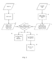
- FIG. 2 is a flow chart of operation of one configuration of processing of the transaction monitor to detect pass-through activity within the transaction area.
- FIG. 3A is a flow chart of processing that the transaction monitor performs in an example configuration in which misidentified items are detected.
- FIG. 3B shows one method of detecting activity in a region of interest to indicate presence of an item.
- FIG. 4 shows processing that the transaction monitor performs in one configuration count items involved in a transaction using analysis of video data.
- FIG. 5 illustrates one method of processing that the transaction monitor can perform to provide object removal and introduction event detection.
- FIG. 6 is a flow chart showing processing steps that the transaction monitor employs in one configuration to provide customer and/or employee presence detection & tracking.
- FIG. 7 is a flow chart of processing steps that show processing that the transaction monitor 32 performs to provide employee/customer object segmentation.
- FIG. 8 is a flow chart of processing operations that the transaction monitor can perform to provide an area comparison method used by detectors when performing video analysis.
- FIG. 9 is a flow chart of processing steps that the transaction monitor performs to provide key frame area comparison.
- FIG. 10 is a flow chart of processing steps that describe transaction monitor processing that provides a passthrough item detection method.
- FIG. 11 illustrates example of frames of video data and that show the appearance of the transaction area before and after detection of an event.
- FIG. 12 is a timeline of events that demonstrates how the transaction manager can determine if there is more than one visual item detection present within the same inter-transaction-item interval.
- the system disclosed herein generally performs video counting or identification of items involved with transactions, as captured in video data, and compares this item identification information with transaction data obtained from a transaction terminal such as a point-of-sale register to identify situations that are suspicious and may indicate fraudulent activity or operator error.
- a transaction terminal such as a point-of-sale register
- the system can automatically (i.e. no human involvement needed) analyze the video data to track items involved in a transaction in the transaction area. Using this information, the system can compare the video analysis of the tracked items to transaction data produced from a transaction terminal to identify suspicious activity.
- FIG. 1 is an illustration of an example environment 300 suitable for use in explaining example embodiment disclosed herein.
- Example environment 300 depicts a retail establishment in which customers 305 can purchase items 307 .
- a transaction terminal 34 such as a point-of-sale terminal or cash register is under control of an operator 308 such as a store employee to allow the customer 305 to purchase the items 307 .
- the transaction terminal 34 includes a scanning device 36 that is able to detect and scan or otherwise read item identities 310 , such as UPC barcode symbols or RFID tags affixed to each item 307 when those items 307 are brought within a predetermined proximity of the scanner device in the 36 .
- the customer 305 approaches the transaction area 301 with a set of items 307 to be purchased.
- the items 307 may be contained, for example, with a shopping cart 311 or other item carrier transported by the customer 305 to the transaction area 301 .
- the customer 305 may carry the individual items 307 to the transaction area 301 .
- the customer 305 removes the items 307 from shopping cart 311 (or from their hands if carrying the items) and places the items into an item input region generally designated as region 302 - 1 within the transaction area 301 .
- the item input region 302 - 1 may be a conveyor belt, countertop or other surface area onto which items to be purchased are placed prior to being detected and read by the scanner device 36 of the transaction terminal 34 .
- the operator 308 such as a store employee interacts with the transaction terminal 34 by logging in or otherwise activating the transaction terminal 34 . This process may involve the operator 308 providing a unique operator identity to the transaction terminal 34 . During operation of the transaction terminal 34 by the operator 308 , the body of the operator 308 generally remains within an operator region 302 - 4 of the transaction area 301 . Once logged in, the operator 308 can begin selecting items for purchase 307 within the item input region 302 - 1 , such as by picking up the individual items 307 by hand. The operator 308 passes each item 307 from the item input region 302 - 1 over the scanner device 36 generally located within an item read region 302 - 2 .
- the operator 308 positions the item 307 such that the item identities 310 affixed to the item can be detected and scan or read by the scanner device 36 .
- the transaction terminal 34 register has the item 307 as an item to be purchased and usually produces a notification to the operator 308 such as a beeping noise or tone to indicate that the item 307 has been successfully identified.
- the operator 308 moves the item 307 into the item output region 302 - 3 which may be another countertop, downstream conveyor belt or the like that holds items 307 to have been successfully scanned or read by or entered into the transaction terminal 34 .
- the operator 308 repeats this process for each individual item 307 such that all items 307 to be purchased are moved from the item input region 302 - 1 , over or through the item read region 302 - 2 (during which scanning of the item takes place) and into the item output region 302 - 3 .
- items 307 may not contain an affixed item identity 310 such as fruit, vegetables or the like.
- the operator 308 manually enters the item identity into the transaction terminal 304 a keyboard or other manual input device to allow the transaction terminal 34 to register the item 307 .
- the operator 308 can indicate to the transaction terminal 34 that the transaction is complete and the transaction terminal 34 calculates the total price of the items 307 to be purchased.
- the customer 305 then provides payment in that amount to the operator 308 and proceeds to remove the items 307 from the item output region 302 - 3 for transport out of the retail establishment.
- the environment 300 further includes a transaction monitor 32 configured in accordance with embodiments of the invention to detect suspicious activity related to a transaction.
- the environment 300 also includes a video source 30 such as one or more overhead video cameras that capture video of the transaction area 301 .
- the video source and will 30 is mounted in an elevated position sufficiently above the transaction area 301 to cover and capture video from the various regions 302 .
- the transaction monitor 32 in this example receives, as input, video data 320 from the video source 30 as well as transaction data 34 from the transaction terminal 34 .
- While the example environment 300 illustrates the transaction monitor 32 as receiving a transaction data 330 and video data 320 directly from the video source 30 and the transaction terminal 34 , is to be understood that the transaction monitor 32 may receive these inputs and either real-time or any later time after processing of items or entire transactions by operator 308 is complete. Additionally, it is not required that the transaction monitor 32 receive the transaction data 330 and video data 320 directly from the video source 30 and transaction terminal 34 . In an alternative configuration, these inputs can be received from a videotape machine (or from digital recorded media) or from the transaction database maintained by another computer system besides the transaction terminal 34 .
- the video source 30 may thus be a real-time source such as a camera, or a delayed source such as a recording device such as a VCR or DVR.
- the transaction terminal 34 likewise may provide real-time transaction data directly from a POS (e.g., cashier terminal or scanner) or the transaction data may be delayed data from a transaction log database in which POS data is stored.
- the transaction monitor 32 operates to identify suspicious activity associated with the transaction area 301 such as sweethearting or pass-through activities, by comparing the video data 320 and corresponding transaction data 330 in order to identify and report suspicious activity.
- this entails the transaction monitor 32 collecting video data 320 from the transaction area 301 including the transaction terminal 34 in which customers 305 purchase items 307 during a transaction.
- the video source 30 such as a camera is preferably mounted in an elevated position above the transaction area 301 to allow video capture of regions 302 from above, though the system is not limited as such.
- the transaction monitor 32 applies automated (i.e. non-human) video analysis to at least a portion or segment of the overhead video data 320 to detect the presence of at least one item 307 associated with the transaction.
- the transaction monitor 32 compares the presence of the item associated with the transaction from the video data (automatically detected by image processing techniques as explained herein) to transaction data 330 indicating items actually purchased by the customer at the transaction terminal (i.e. items 307 read or scanned by the terminal 34 ) to identify items in possession of the customer 305 that were not purchased at the transaction terminal (i.e. that were passed through the transaction area 301 without being scanned or entered into or read by the transaction terminal 34 ).
- the discrepancy between the presence of one or more items identified via automated processing of the video data 320 in comparison to items identified within the transaction data 330 indicates suspicious activity that the system disclosed herein can detect.
- the suspicious activity may be the result of operator error on behalf of the operator 308 , or actual fraudulent activity that may include sweethearting or pass-throughs.
- the transaction monitor 32 can analyze all or a portion of the video data captured from the transaction area to automatically detect items based, for example, on activity of objects that pass through the transaction area, activity of objects within a specific region of interest within the transaction area, activity of objects within a plurality of specific regions of interest within the transaction area, activity of objects entering into specific regions of interest within the transaction area and/or activity of objects exiting the specific regions of interest within transaction area.
- Analysis of all or a portion of the video data produces, in one configuration, a set of detection events indicating detection of one or more items by at least one detector within at least one region of interest 302 of at least one portion of the video data.
- the transaction monitor 32 can detect item detection from video analysis in only one region of interest 302 , or in many regions 302 . Notice in FIG. 1 that the transaction area 301 is divided or enumerated into several regions 302 - 1 through 302 -N. Each of these areas or regions can be considered a region of interest 302 and the video data 320 can capture activity in some, all or only one of these areas that may be indicative of an item involved in the transaction.
- the transaction monitor 32 applies a detector to perform image processing in a region of interest.
- the detector is generally an image processing algorithm that can detect the presence of an item in that region. Item presence can be detected, for example, by applying a detector processing to the input item region 302 .
- the transaction monitor 32 compares the set of detection events for that detector to at least a portion of transaction data (i.e. the portion that contains transaction information that coincides with the video data) to identify at least one apparent discrepancy in a number of items detected by that detector from a number of items indicated in the portion of the transaction data.
- the transaction monitor 32 can identify an overall suspicion level for the transaction based on apparent discrepancies identified by the detectors(s).
- video processing or analysis includes dividing the transaction area 301 into a plurality of regions (e.g. 302 - 1 and 302 - 3 ) through which objects move in sequence during at least a portion of a transaction.
- the transaction monitor 32 can perform automated video detection of an item as the items move through the plurality of regions in a sequence to obtain a pattern represented by one or more video parameters. The pattern thus represents video events of items that moved through the regions during all or part of a transaction.
- the transaction monitor 32 can obtain transaction data 330 identifying items detected by the transaction terminal 34 during the portion of the transaction that corresponds to the video data that is analyzed, and can automatically comparing the video parameter to the transaction parameter by determining if the pattern representing video events of items from all or part of the transaction indicates a discrepancy from the transaction data identifying items detected by the transaction terminal during all or the same part of the transaction. If a discrepancy exists, the transaction monitor 32 identifies the transaction outcome to be a suspicious transaction.
- sequences of different detection events can be used to identify existence of an item in the video data.
- the transaction monitor 32 can concurrently compare sets of detection events from detectors with the transaction data to identify a discrepancy in a number of items processed in the transaction area.
- performing automated video detection of the items can include identifying a removal event in an item input region 302 - 1 that indicates the operator 308 has removed an item 307 from the item input region 302 - 1 , and can also include identifying an introduction event in an item output area that indicates an operator has placed an item into the item output area.
- a sequence of events such as removal, introduction, removal introduction, and so forth can be produced from the video analysis if multiple regions of video data are monitored.
- This sequence can be time synchronized with transaction data indicating, for example, scans of items, so that a legitimate pattern appears as removal, scan, introduction, removal, scan, introduction and so forth, whereas a suspicious pattern might appear as removal, scan, introduction, removal, introduction. Notice the second scan event is not present, indicating a potential fraudulent or otherwise suspicious activity.
- the transaction monitor 32 can determining if the video event is not identified as a transaction event in the transaction data, and in response, can identify a specific segment 328 of the video data that indicates where the video event not identified as a transaction event exists.
- the transaction monitor 32 can identify and transmit the specific segment of video data that indicates where the video event that is not identified as a transaction event exists (i.e. in the video clip 328 ) to a reviewer to review the segment of video data 328 to review the suspicious activity of an operator with respect to purchase of items during the transaction.
- the system disclosed herein provides an approach of actual counting of items or item detection events and is a more robust and accurate method of identifying incidents of items being passed through the transaction without being scanned.
- the system is unaffected by scan delays and since the system can determine that more items were part of a transaction than were scanned, the system can serve as a very clear indicator that theft or error on behalf of the operator has occurred.
- Another kind of error, independent of item detection comparisons, is the misidentification of items. This may be due to fraud such as “ticket or label switching” where the barcode code or other item identity 310 may be overlaid with a bar code from lesser-priced item or “discounting” where the operator 308 intentionally manually enters a code or item identity into the transaction terminal 34 for a lesser priced item.
- the system disclosed herein provides an approach of isolating the item images for comparison directly from video of typically performed transactions.
- the transaction monitor 32 can perform image comparison to determine if an image of an item associated a detection event (e.g. an event indicating presence of an item in video data) substantially matches a previously stored image of an item.
- the transaction monitor 32 can identify the transaction as potentially including a label-switching event indicating potential suspicious activity. Because this approach allows the operator 308 to handle the item 307 normally, it does not require alteration of the manner in which transactions are typically performed. The system also does not impact or slow down the operator's performance of the transaction. This is of particular importance to professional operators as they are assessed on their speed of performance. Because the operator is not asked to alter his or her behavior, the system can be put in place to detect dishonest employees without their knowledge that anything new has been put in place.
- FIG. 2 is a flow chart of operation of one configuration of processing of the transaction monitor 32 to detect pass-through activity within the transaction area.
- the transaction monitor 32 obtains video data originating from at least one video camera that monitors a transaction area 301 .
- the video clip 2 from video data 320 for at least a portion of one transaction and the corresponding transaction data 8 (from transaction data 330 in FIG. 1 ) for that transaction are analyzed to track items 307 involved in the transaction in the transaction area 301 .
- Any time span of video data 320 and corresponding transaction data 330 may be handled (i.e., a portion of or more than one transaction), but for the sake of clarity and simplicity, this example will discuss one transaction being handled at a time.
- identifying the presence of an item can be done using an area differential technique.
- the transaction monitor 32 defines a region of interest within the transaction area, such as the input item region 302 - 1 .
- the transaction monitor 32 operates a detector to automatically identify a first frame of video data (i.e. taken at a first time) that indicates a first set of items in the region of interest 302 - 1 . This may be, for example, the initial set of items 307 placed in that area 302 - 1 by the customer 305 for purchase. Thereafter, the transaction monitor 32 automatically identifies a second frame of video data (i.e.
- the transaction monitor 32 can automatically indicate the visual distinctness of the first set of items from the second set of items as an event indicating an item existed within the region of interest 302 - 1 of the video data.
- step 10 the transaction monitor 32 obtains transaction data associated with the transaction terminal 34 associated with the transaction area 301 .
- the transaction data indicates if the item 307 was registered as a purchase item with the transaction terminal 34 .
- the transaction monitor 32 compares the video analysis of the tracked items to transaction data produced from a transaction terminal to identify suspicious activity.
- the transaction monitor 32 identifies suspicious activity when the transaction data is missing transaction data for an item for which an event indicates the item existed within the region of interest 302 . This is an event-based comparison to associate each video detection event with a transaction event from the transaction data.
- the video clip 2 is analyzed in step 4 to visually detect the presence of items 307 actually involved in the transaction (event detection can be used).
- the transaction monitor 32 analyzes at least a portion of the video data to obtain at least one video parameter concerning at least a portion of a transaction associated with the transaction area 301 .
- the video parameter may thus be a video count of items whose presence was detected.
- the transaction monitor 32 also obtains at least one transaction parameter originated from a transaction terminal 34 associated with the transaction area.
- the transaction monitor 32 in step 10 analyzes the transaction data 330 to obtain records of items 307 involved in the transaction. From these records can be determined an expected count of items reflected in the transaction data.
- step 14 the transaction monitor 32 compares the actual or video count 6 against the expected, scan or transaction count 12 . If the counts do match, then the transaction monitor 32 can flag the transaction as non-suspicious as in step ( 16 ). If the counts do not match, then the transaction monitor 32 flags the transaction as suspicious (e.g. potentially fraudulent) in step 18 .
- the transaction monitor 32 identifies a video count of items detected within the transaction area using video analysis and identifies a transaction count of items within the transaction area by analyzing transaction data associated with at least a portion of the transaction. By comparing the video count to the transaction count, if the video count is different from the transaction count, the transaction monitor 32 can indicate a transaction outcome that represents suspicious activity, such as a fraudulent transaction or operator error. Depending upon the configuration, the transaction monitor 32 may provide additional information such as a suspicion level based on a metric such as the difference between the actual count and expected count.
- a suspicion level can be used to rank a suspicion level as being low, or high, or in a range.
- each cashier operating a transaction terminal or cashier station typically logs into the system with a unique identification via his or her register (e.g. via a keyboard) to being processing transactions for customers.
- the system disclosed herein can performed as explained herein, and if a suspicious transaction is detected (e.g. a transaction count does not match a video count), the system can look at a past history of this particular cashier (based on their unique identity) that can be stored in a database that indicates how frequently this cashier performs transactions that are labeled as being suspicious.
- the transaction monitor 32 can assign a suspicion level to the segment of video 328 .
- the suspicion level indicates a level of suspicion produced from automated video analysis of video data in comparison to transaction data.
- the transaction monitor 32 can adjust a suspicion level associated with the transaction outcome based on many factors. Examples include:
- FIG. 3A is a flow chart of processing that the transaction monitor 32 performs in an example configuration in which misidentified items are detected.
- the video data 40 for one transaction and the corresponding Transaction Data 46 for that transaction are analyzed. Any time span of video and corresponding transaction data may be handled (i.e., at least a portion of or more than one transaction), but for the sake of clarity and simplicity, this example will discuss one transaction being handled at a time.
- step 42 the actual item images 44 are isolated from the video data 40 .
- One method of image isolation is described as part of the removal/introduction detection method (discussed below).
- step 48 the expected item images 52 corresponding to the items in the transaction data are extracted from a database of item images 50 .
- the database of item images may be organized in any fashion, but one way that is convenient in a retail environment would be by SKU number.
- the transaction monitor 32 can also populate the database with images as the transaction monitor 32 proceeds to isolate more images from each consecutive transaction. In this manner, the retailer is not required go through the time and expense to provide a database ahead of time. Instead, the database can be essentially learned by capturing and storing video of enough transactions with the same items.
- the actual item image is compared against an expected item image.
- the actual item images can be isolated and compared one at a time or as a group against their corresponding expected item images.
- the transaction data contains only a full list of items but no data with respect to the sequence or times at which they were scanned, there is no basis by which apriori correspondence between individual images can be established. Therefore the entire set of actual item images would need to be compared against the entire set of expected item images. If, however, sequence or timing transaction data is available that allows a synchronization process to associate scanned item data with video data (e.g.
- the timestamp of the scan is substantially synchronized with a timestamp of the video
- the correspondence between images can be established, e.g., the first actual item image is compared with the first expected item image, and so forth.
- the option exists to compare each individual actual item image against its one corresponding expected item image.
- step 56 if the images are found not to match, then transaction is flagged as suspicious in step 58 . If, as mentioned above, the actual item images are being compared one-by-one against the expected item images, then the option exists to flag a specific item as suspicious rather than the entire transaction.
- step 60 if the images are indeed found to match, then the transaction is considered non-suspicious.
- the actual item image or images 44 may be incorporated into the database of item images ( 50 ) if desired. For example, it may not be desirable to introduce new images into a professionally pre-populated database, whereas it is necessary for a “learning” database.
- the transaction or individual item as described above would then be flagged as non-suspicious.
- the transaction monitor 32 performs image recognition of an item detected within the transaction area using automated video analysis to produce a video identity of an item. In doing so, the transaction monitor 32 obtains at least one transaction parameter by identifying an expected item identity of an item detected within the transaction area. The transaction monitor 32 then automatically compares the video parameter to the transaction parameter by comparing the video identity of the item to the expected identity of the item. If the video identity is different from the expected identity, the transaction monitor 32 indicates a transaction outcome that represents suspicious activity.
- Regions of interest may include any area where items of the transaction may be.
- the regions of interest may include the shopping cart 302 -N, customer region 302 - 5 , an incoming conveyor belt region 302 - 1 (i.e., object input region or area), scanning region 302 - 2 , and an outgoing conveyor belt 302 - 3 or bagging area (i.e., object output area), and operator region 302 - 4 .
- the operator may vary with the region of interest. For example, in the supermarket scenario, if items are being counted in the transfer from the cart 311 to the incoming belt region 302 - 1 , then the customer 305 doing the transfer may be considered the operator. Similarly, if the cashier operator 308 is scanning the items at the transaction terminal 34 , then the cashier 308 is considered the operator.
- the counts across these regions of interest 302 are considered in combination to provide a more robust method of counting. For example, the number of detections across the incoming item input region 302 - 1 , scanner or item read region 302 - 2 , and bagging or other item output region 302 - 3 area in one configuration are compared to see if they coincide. If they do not, the average number of detections may be used. Likewise, the sequence of counts or detection events can also be taken into consideration.
- each accurately counted item would be counted first at the incoming area as an item removal event, then at the scanner as a scan event, and then again at the bagging area as an item introduction event (each event or count being detected and produced by a detector analyzing that region of interest in the video data 320 ).
- the count of the item is seen as a sequence or pattern of a certain type of event at a certain area, such as an object removal event when the operator removes an object from the belt or object input region 302 - 1 , followed by another type of event such as an introduction event when the operator places the object into the object output region 302 - 3 or downstream conveyor belt.
- a removal event an operator picking up an object for scanning, and removing that object from the object input area
- an introduction event the operator placing the item down on the output belt or object output area
- a count is registered only in one stage or region 302 (e.g. 302 - 1 item event detection) of the sequence but not the other one or two regions (no detection at regions 302 - 3 and/or 302 - 2 ), then that one count or event may be considered an error and/or may be labeled as suspicious.
- the system can determine which scan detection events (i.e. transaction events) or scan counts match up with which video counts (e.g.
- a video count being, for example, an item removal event followed by an item introduction event if analyzing two regions, or if analyzing only a single region such as the item input region 302 - 1 , then a video count or event can be a single removal event of an item 307 from that region 302 - 1 as detected by the video analysis).
- the scan counts or events match one to one with the video counts of events, there is no apparent fraudulent activity and the transaction is not flagged or labeled to further review.
- time synchronizing the video data with the scan data may be inherent in the data collection process when the video data is collected concurrently with the transaction or scan data, or may be done in post processing via algorithmic comparison of timestamps of scans with video frames or patterns of detection events
- a pattern such as a removal event, followed by an introduction event (for a first object, with no scan or transaction event identifying the presence of the item in the transaction data), followed by another removal event (for a second object) is detected, then the transaction can be labeled as potentiality fraudulent or suspicious.
- the transaction monitor 32 correlates video timestamps of events from the analysis of the video data to transaction timestamps of items reflected as having been transacted in the transaction data to identify events indicating an item in the video data that does not have a corresponding record in the transaction data, thus indicating suspicious activity.
- One of such processing techniques disclosed herein is to count items currently in a region of interest.
- One way to count the items currently in the region of interest is to count the items visible in a static image of the region of interest. This assumes that the individual items can be segmented and disambiguated well, and this approach may therefore be particularly challenging in the case of connected or overlapped items.
- a small number of items slowly placed on a moving conveyor belt one by one may indeed be spread out on the belt such that they do not touch or overlap with each other. In such a case, counting the items against the background of the belt from a static image of the belt yields the accurate number of items in the transaction.
- the items may begin to pile up against each other at the end of the belt. As they pile up, segmentation of specific items via video analysis may become very difficult and analysis of a static image may yield poor results concerning a count of items placed on the belt.
- the transaction monitor 32 can utilize counting of periods of activity. Periods of activity within the region of interest may indicate the introduction, removal, or passing through of an item. Activity measures include simple detection and measurement of motion in the region. A “tripwire” (i.e., looking for motion along an edge of the region of interest) can take into account the direction of entry into the region. In a supermarket scenario, for example, a tripwire along the customer facing end of the incoming belt area may be used to count each time a customer reaches in to place a new item on the belt in the item input region 302 - 1 .
- Two or more tripwires may be established and used to determine that motion of an item travels from one side of the region of interest across to another side of the region of interest.
- two tripwires on either side of the scanner area can detect motion in a particular direction depending on the order in which they are triggered.
- tripwires Another use of tripwires is to cover an entire large region of interest with a series of tripwires (perpendicular to the direction of motion of interest) to detect progression of motion from one end to the other.
- a series of tripwires can be used to detect the forward progression of objects from the incoming area to the bagging area even as the objects are exchanged from one hand to another over the scanner area.
- an operator object i.e. the portion of video data 320 containing the operator 308
- the count can increment only upon the operator object itself (e.g. his or her arm or hand) entering and exiting the region.
- the detector can be more accurate to trigger an item detection or count only if the operator's hand enters the region of interest (e.g. 302 - 1 ). If the end of the operator object (i.e., his or her hand) has as part of its color histogram colors other than its own, then it can be considered more likely to be a hand entering or exiting the region of interest with an item.
- FIG. 3B shows one method of detecting activity in a region of interest to indicate presence of an item.
- step 432 identifies objects and creates an object map.
- Step 434 applies relevance filters (e.g., skin detection, skin plus object color histogram, etc.) to make sure that only objects or activity of interest are being considered. For instance, in a video image of a retail store environment, an operator may reach across the scanner region in order to interact with the touch screen of the transaction terminal. Such activity in the region of interest is not indicative of item presence, and can therefore be ignored by filtering out cases where the operator object connects with the graphical region of the touch screen in the video image.
- Step 436 incorporates the current object map into a motion map of the motion over time in the image.
- Step 442 then analyzes the motion map to identify motion in the direction of motion 438 with the region of interest 440 . If step 444 determines that the motion has completed all the way across the region of interest, then it is recorded as a video detection event in step 446 . If step 448 determines that more video remains, then step 450 will advance to the next frame of video and continue from step 432 . If not, then the records of video detection events is returned in step 452 . As an example, with a direction of interest being from the item input region toward the item output region across the region of interest as the scanner area, the transaction monitor 32 could observe the scanner area for activity indicative of items present in the transaction.
- the transaction monitor 32 is able to count the introduction or removal of objects that may be items, or an operator or customer object. Objects being newly introduced or removed from one or more regions of interest 302 in one configuration is an indicator of item detection or count change. For example, in a supermarket scenario, if an item is removed from the incoming conveyor belt, or if it is introduced into the bagging area, (or both cases if considered in combination) then that indicates an additional item involved in the transaction.
- One way to detect introduction or removal is to detect color histogram change in the region of interest.
- Another way to detect introduction or removal of an additional object is to detect object appearance or disappearance.
- image detection algorithms constantly incorporate static objects into the background image used for object segmentation. When a new object is added to the image, it will appear as the only one object in the foreground. Similarly, when an object is removed, it leaves behind a “ghost” (i.e., an alteration in the place of the image it once occupied) that will likewise appear as an object in the foreground. In either case, the object is subsequently counted and thereafter incorporated into the background to prepare for counting the next item.
- One benefit of this method is that it readily facilitates isolation of an item image.
- that items image may be cut out as the isolated item image.
- an item is removed (i.e., a ghost object appears), that item's image may be cut out from the frame that preceded removal.
- One challenge in the above kinds of methods is that the operator's arm itself will appear as an object in the region of interest. Two example configurations disclosed herein handle this challenge by either disregarding the operator's arm, or use only images without the arm in the region.
- the arm object In order to disregard the arm object, it is first identified. This can be accomplished by checking all the objects in the video data to see which one extends (e.g. using edge detection) from the larger operator object 308 in the operator region 302 - 4 outside (or into) the region of interest 302 - 1 . This object can then be assumed to be the arm of the operator 308 . Skin detection may also be performed to further ensure that the object is indeed an arm and/or hand. Then the arm object may be removed from the region of interest's object map leaving only items of merchandise 307 that may have been introduced or removed. In order to use only images without the arm in the picture, a tripwire may be used along the edge of the region of interest closest to the operator 308 to see if any object is crossing it.
- edge detection e.g. using edge detection
- the transaction monitor 32 is able to identify motion of an operator 308 within a region of interest (e.g. 302 - 1 ) in the transaction area that indicates the presence of an item 307 for transacting (e.g., for purchase) within the region of interest.
- the transaction monitor 32 can indicate if a record of the item occurs within transaction data corresponding to identifying the motion of the operator can automatically identify a situation when motion of the operator within the region of interest 302 - 1 in the transaction area indicates the presence of the item 307 for transacting, but the record of the item does not occur in the transaction data.
- the transaction monitor 32 can indicate suspicious activity.
- modeling the operator such as the cashier 308 (or a customer 305 if the environment 300 in FIG. 1 is a self checkout terminal 34 ) can be used to identify the motion associated with handling each item 307 in the transaction.
- the operator may be modeled as a torso with two arms extending out from it.
- the torso of the operator can be identified by its location at the transaction terminal 34 .
- the arms can then be identified as two faster moving extremities that extend from the torso.
- the handling of an item 307 may then be modeled as the extension of one hand to the incoming belt area or item input region 302 - 1 , followed by the bringing together of the two hands as the item is passed from one hand to the other around the scanner area or region 302 - 2 , then followed by the extension of the second hand toward the bagging area or item output region 302 - 3 .
- either a single region of interest may be monitored with one item counting technique, or multiple counting methods may used in a region of interest 302 to achieve a count for items in that region 302 .
- the counts and sequence of counts from multiple regions of interest may be used in combination to achieve a more accurate count for the entire transaction.
- FIG. 4 shows processing that the transaction monitor 32 performs in one configuration count items involved in a transaction using analysis of video data 320 .
- One way to count the presence of items is to count the operator's removal of items or introduction of items from or to a region of interest. For example, whenever an operator lets go of an item within a region of interest such as the bagging area, that item can be safely assumed to be an item of merchandise being introduced into the bagging area. Conversely, one way to count removal of items is to count the removal of the items from the item input region 302 - 1 .
- the first step 72 is to identify the objects within that image. One way this is typically done is by comparing the current frame against a model of the background so as to extract the foreground components, or the items, in the image.
- the operator object i.e. a rendition of the operator 308 in the video frame
- the operator object is isolated. One way to do this is to use apriori information of the likely location of the operator 308 . For example, if it is known that the operator 308 will stand in a particular confined location such as operator region 302 - 4 , then it may be assumed that the largest moving object in that region is the operator 308 .
- Another way to identify and isolate the operator object in video data is to identify the operator object reaching across the edge of the boundary of the region of interest 302 - 3 as the operator, for example, reaches into the bagging area to place another item 307 .
- the next step 76 checks for the graphical introduction or removal event, such as when the operator object and an item (or the object's ghost as described below) within the region of interest separate from one another graphically.
- a removal event indicates the operator has picked up an item in the item input region 302 - 1 .
- step 78 if the removal has occurred, then the count is incremented in step 80 .
- step 82 if there is more video remaining, then processing advances to the next frame of video in step 84 , and the loop continues again with step 72 . When video for the transaction is finished, the count is returned in step 86 .
- each removal of an object from the item input area 302 - 1 (or introduction of an object into the item output area 302 - 3 ) creates a corresponding removal (or introduction) event that can then be correlated with the transaction data (or the pair can be correlated, if using multiple regions of interest).
- FIG. 5 illustrates one method of processing that the transaction monitor 32 can perform to provide object removal and introduction event detection.
- the current image 90 and an updated background image 92 is taken as input by step 94 in which they are compared (by subtraction and thresholding) to create a binary object map 96 .
- This object map contains any new objects (i.e., items) in the image that are not part of the updated background, as well as the operator object which is also not part of the updated background.
- the current operator object 100 is isolated from the object map.
- the cashier operator 308 stands in a defined space (e.g. region 302 - 4 ) before the register, this is done in one configuration by finding the largest moving object standing within the that space. (Alternatively, this can also be done by finding the object overlapping a smaller “tag” region which is likely to be touched by the operator.) This object is considered the operator object.
- the current operator object 100 and the previous operator object 102 are used to define an immediate region of interest 106 .
- the non-overlapping region of the previous operator object makes up the immediate region of interest for the following reason: If an item were held by the operator 308 in a previous frame of video data, it would have been part of the previous operator object. Therefore, if that item were released in the current frame, it would have been left somewhere in the area of the previous operator object. And because it was released, it would not be part of the current operator object. Therefore, if an item were released since the previous frame, its object would appear in the region of the previous operator object that does not overlap with the current operator object. Likewise, if an item were picked up in the previous frame, its ghost (i.e., its absence where it was removed from the background layer) in this frame would appear in the same immediate region of interest described.
- the object map 96 is checked to see if there is a new object (i.e., item) or object (i.e., item) ghost that has appeared in the immediate region of interest 106 . If not, then in the next step 120 , all regions outside the operator object are incorporated into updating of the background to be used for the next frame. Lastly, the occurrence of no removal/introduction is returned.
- step 110 if there is indeed a new object in the Immediate Region of Interest, then the next step 112 is to isolate that object (i.e., item) image, i.e., copy it from the current frame. If an object removal (disconnection from ghost) is being detected, then the image is taken from a frame before the previous frame when the item was picked up.
- object i.e., item
- the isolated image of the actual item will be compared with the database of expected objects (e.g., a database of items along with their photographs). Note, this is part of the item misidentification detection method described above. Then the object image is incorporated into the updating of the background to be used for the next frame. Again, in the next step 116 , all regions outside the operator object, including the removed or introduced object are incorporated into updating of the background to be used for the next frame. Lastly the occurrence of a removal (or introduction) is returned.
- the database of expected objects e.g., a database of items along with their photographs.
- FIG. 11 illustrates example of frames of video data 501 and 502 that show the appearance of the transaction area 301 before (video data frame 501 ) and after (frames 502 ) detection of an event.
- the detected event in this example happens to be an introduction event in which the operator 308 places an item 307 (a milk jug in this example).
- Each frame 501 and 502 is divided into four quadrants, an upper right and left, and a lower right a left.
- the upper left quadrant of each frame shows the original frame of video data, wherein the lower left quadrant shows the updated background image, produced as explained via the above processing.
- the upper right quadrant of each frame 501 and 502 shows the operator object 308 , and the lower right quadrant shows the difference binary image or map.
- the video analysis as previously discussed can detect this difference in images and can indicate this activity as an item detection event, in this case an item introduction event, accounting for the existence of that item in the transaction.
- the video analysis is able to detect items involved in the transaction, and as explained above, the transaction monitor 32 can use this information in comparison with transaction data from the transaction terminal 34 to ensure that each item detected in the video data has a corresponding entry (e.g. scan, read, item identify or price) in the transaction data. If this corresponding transaction data does not exist for this object, the transaction monitor 32 can indicate suspicious activity.
- the system can also incorporate bottom-of-basket detection or in-basket detection to identify from an elevated view items existing underneath or within a possibly moving shopping cart, for example.
- the transaction monitor 32 in one configuration can analyze at least a portion of the video data by defining at least one region of interest within the video data and calculating the object map that identifies a change between a current image of the region(s) of interest and an updated background image of the region(s) of interest. Then, by isolating at least one operator object within the region(s) of interest, the transaction monitor 32 can detect if an analysis of the object map and the operator object identifies either the removal or introduction of an object to the region of interest 302 . In this manner detection events can be maintained that indicate a count of presence of object in the video data. This can be done for a single region or for many regions 302 , and can be done on an item by item basis or for larger portions of a transaction or for the entire transaction (i.e. all items).
- the system needs to compensate for autogain functionality found in some cameras or other video sources.
- Autogain seeks to balance the brightness in a camera's three color channels over the entire image. This could lead to unfortunate shifts in color if a large noisance object (i.e. an object appearing in the scene but not part of the transaction or transaction area) appears within the field of view of the camera.
- the system needs to essentially undo that shift in color.
- the challenge is that the system cannot compute any statistics over the entire image, as the system will arrive at the same conclusion that the camera's autogain came to. Instead, the system needs to restrict its focus to the transaction area, more importantly, to the objects in the transaction area that that remained stationary but exhibit a color or brightness shift.
- the current image is compared (e.g., via subtraction and thresholding) from the current updated background image to get a noisy binary map of foreground/background pixels.
- the background pixels only are then used to compute the color statistics for the current image and the background image. These background pixels are used because they correspond to the same, static objects in the world, and they exhibit the color shift effect that needs to be correct for.
- the statistics the pixels labeled as background are computed, the change is applied to the current image to bring its colors into correspondence with the colors of the background image and therefore in correspondence with the rest of the images being processed by the system.
- this preprocessing step is done, the usual video processing steps proceed. In this way, the transaction monitor 32 can compensate for autogain being applied to the video source prior to video analysis.
- the transaction monitor 32 can define an object input region 302 - 1 as a first region of interest and can define an object output area 302 - 3 as a second region of interest.
- detecting an object removal event and/or an object introduction event can include detecting an object removal event when an operator removes an object from the object input area, and/or detecting an object introduction event when an operator places an object in the object output area.
- the transaction monitor 32 can increment a video count as the at least one video transaction parameter in one configuration, or alternatively can generate respective events for the removal and introduction that are then processed during comparison to transaction data to identify items not in the transaction data but that appear in the video data.
- At least one of the regions of interest includes a conveyor belt that translates a position of objects on the conveyor belt over time as captured within current and previous frames of video data.
- the item input area where removal detection events are generated as operator remove items 307 may be a conveyor belt that feeds the items 307 to the operator 308 .
- the transaction monitor 32 can compensate for the movement or translation of the items as they move from position to position in successive video frames.
- the transaction monitor 32 can analyze at least a portion of the video data and can include correlating previous and current frames of video data within the region of interest to determine an amount of translation of the position of objects on the conveyor belt.
- the transaction monitor 32 can account for the amount of translation of the position of objects on the conveyor belt when detecting object removal events and/or object introduction events.
- FIG. 8 is a flow chart of processing operations that the transaction monitor 32 can perform to provide an area comparison method used by detectors when performing video analysis.
- the Video Source ( 200 ) When the video source 200 provides a frame of video, the Video Source ( 200 ) outputs a frame of video.
- the first step 202 is to identify the objects within that image of that frame. One way this is done is by comparing the current frame against a model of the background so as to extract the foreground components, or the objects, in the image.
- the operator object is isolated.
- One way to do this is to use apriori information of the likely location of the operator. For example, if it is known that the operator will stand in a particular confined location, then it may be assumed that the largest moving object in that location is the operator. Another way to do it would be to identify the object reaching across the edge of the boundary of the region of interest as the operator reaching into the bagging area to place another item.
- the system checks if the operator object extends into the region of interest.
- the system checks, in step 210 , if the operator was in the region of interest in the previous frame as well. If not, then the previous frame is saved in step 212 as the key frame 1.
- Key frame 1 therefore, is the image of the region of interest before the operator object entered the region of interest.
- the system will be able to determine whether a new object was introduced or removed from the region of interest. Regardless of the decision in step 210 , the system will then proceed onto checking for more video in step 224 .
- step 208 decides that the operator object is not in the region of interest
- step 214 checks if key frame 1 is already saved. If no, then that indicates that the operator object had not yet entered the region of interest as of the previous frame. And since the Operator Object is still not in the region of interest in the current frame either, it is not worth examining the region of interest for any new object introduction/removal by the Operator. The system then proceeds onto checking for more video in step 224 .
- step 214 If the decision in step 214 is yes, that indicates that operator object had previously already entered the region of interest and had not yet exited as of the last frame. Therefore, now that the operator object is not in the region of interest of any longer, the operator object must have just exited. Therefore, the current frame is saved in step 216 as key frame 2.
- step 218 the object areas for key frame 1 and key frame 2 are compared. This process is described in greater detail below.
- step 220 decides that there was indeed a substantive change (e.g., above a threshold amount) in the object area between key frames 1 & 2, then step 222 increments the item count or produces a detection event.
- a substantive change e.g., above a threshold amount
- step 220 the system proceeds to step 223 where it resets (or deletes) key frames 1 & 2 to signify that the operator object is no longer considered to be within the ROI.
- step 224 the system then proceeds to step 224 to check if there is more video remaining. If no, then the item count is returned. If yes, step 228 advances the video the next frame and the system restarts the loop at step 202 .
- FIG. 9 is a flow chart of processing steps that the transaction monitor 32 performs to provide key frame area comparison.
- the diagram describes one example method by which two key frames can be compared to find change in the object area within the region of interest indicating object introduction or removal.
- key frame 1 is the frame of video before the Operator Object entered the region of interest.
- Key frame 2 is the frame of video after the Operator Object has exited the region of interest.
- the Empty Base Image is the image of the scene where the region of interest is without objects.
- the region of interest 259 is a binary map highlighting which region of the image is of interest.
- Steps 256 , 258 , 260 , and 262 describe processing related to key frame 1.
- step 256 key frame 1 and the empty base image are compared (by subtraction and thresholding) to create a binary object map 258 .
- This object map contains any new objects in the image that are not part of the empty base image, including the operator object and other objects within the region of interest.
- step 260 the objects within the region of interest are isolated by taking the object map 258 and masking it with the region of interest 259 , such that only the objects within the region of interest are left.
- One way to perform the masking is by performing an “AND” operation between the binary object map and the binary region of interest map.
- the new resulting object map is the key frame 1 object map 262 .
- Steps 264 , 266 , 268 , and 270 perform the analogous creation of a key frame 2 object map 270 from key frame 2 254 .
- step 272 the amount of translation within the region of interest between key frame 1 and key frame 2 is determined. This can be done so by using standard techniques like correlation, sum of squared differences, flow analysis etc. to register the region of interest and find the amount of translation that occurred between key frames 1 and 2. Step 272 produces a translation amount 274 .
- the translation amount 274 is applied by step 276 to register the key frame 2 object map 270 with the key frame 1 object map.
- the registered key frame 2 object map 278 is produced.
- Step 280 compares the area of the key frame 1 object map 262 with the area of registered key frame 2 object map 278 .
- the area of each of the object maps can be computed as the sum of the binary object map.
- step 282 if there was a significant enough change in the area (i.e., above a threshold), then return Yes that the area changed 284 . Otherwise, return No, that the area did not change 286 .
- FIG. 10 is a flow chart of processing steps that describe transaction monitor 32 processing that provides a passthrough item detection method. Just as passthroughs can be detected by comparing the expected and actual item counts over the time window duration of an entire transaction, so too is it the case that the time window can be of shorter be duration allowing the comparison to be done essentially on an item-by-item basis.
- the item detection process 402 takes and advances video from the video source 400 until detecting the next item involved in the transaction. This can be done by any of variety of methods including but not limited to introduction removal detection, area difference comparison, scanner motion detection, etc. This produces an item detection time 404 .
- step 410 the system takes transaction item time data 408 from the transaction data source ( 406 ) and compares it with the item detection time 410 .
- the comparison indicates whether or not there is a transaction item time that corresponds to the item detection time.
- Step 412 checks the result of the comparison. If there is a transaction time corresponding to the item detection time, then the expected and actual activity match, and the current visually detected item is flagged as non-suspicious 414 . If there is no transaction time corresponding to the item detection time, then the expected and actual activity have a discrepancy, and the current visually detected item is flagged as suspicious and entered into the suspicious item log 416 .
- correspondence can be determined is by whether an as yet uncorresponded transaction item time is present within a sufficiently close time (e.g., less than some static or dynamic threshold) of the item detection. If so, then the detection can be matched to a transaction time; if not, then the item detection is considered uncorresponded.
- Another method involves keeping a running tally of the total number of items detected as well as the total number of transaction items. When the detected items outnumber the transacted items by more than some threshold (e.g., more than one item), then the last detected item is considered uncorresponded, and the tallies are reset until the next uncorresponded item.
- Another method is to see if there is more than one visual item detection present within the same inter-transaction-item interval as in the example in FIG. 12 . If so, then at least one of the item detections must not correspond to a transaction item time. In such a case, the inter-transaction-item interval itself may be considered suspicious.
- Step 418 if there is more video remaining, then system proceeds to step 402 to restart the loop. Otherwise, the system proceeds to step 420 to return a log of the suspicious items.
- the system provides a passthrough item detection method that can identify passthroughs as suspicious activity.
- Other configurations include the ability to employ customer and/or employee presence and tracking. Such configurations can use an “over-the-shoulder” perspective camera shot in addition to the simpler top-down camera shot.
- the method can identify the employee as the object on the near side of the counter by identifying the object occluding the counter.
- the customer object is identified as the object seen over the counter but cut off by the upper edge of the counter.
- FIG. 6 is a flow chart showing processing steps that the transaction monitor 32 employs in one configuration to provide customer and/or employee presence detection & tracking.
- step 254 the input image 250 and the background base image 252 are compared to produce an all objects binary map showing all non-background objects in the image.
- One typical method of such comparison is subtraction, followed by thresholding, followed by morphological operations to “clean” the binary map of noise.
- step 256 employee/customer object segmentation is performed on the the all objects binary map as described in the following section and in FIG. 7 that described employee/customer object segmentation.
- step 268 if an employee object exists, then the employee object is labeled in step 270 .
- step 258 if a customer object does not exist, then the process will advance to the next frame of video in step 284 . Otherwise, in step 260 , if the same customer object is present in the previous frame, then step 262 will determine if the customer object is stationary over time. If so, then the customer object is actually probably an inanimate object such as shopping cart. In that case, the process resets the customer flag in step 280 and then incorporates the stationary object into the background base image in step 282 . If the customer object is not stationary over time, then it is assumed to indeed be a human and the object is labeled as a customer in step 266 . Stationary or not, the process then advances to the next video frame in step 284 .
- step 260 if the same customer object was not present in the previous frame, then the customer object is tracked in step 272 .
- the tracking is done by tracking shifts in the centroids of the objects of interest. If the customer object is near the counter region (e.g. 302 - 1 , 302 - 2 , 302 - 3 ), i.e., as if standing at the counter, then it is determined whether or not is a stationary object like a cart. If so, then the process shifts to step 282 as described previously. If not, then the customer present flag in step 278 and the customer is labeled in step 266 .
- FIG. 7 is a flow chart of processing steps that show processing that the transaction monitor 32 performs to provide employee/customer object segmentation.
- step ( 204 ) the input image 200 and the background base image 202 are compared to produce the all objects binary map showing all non-background objects in the image.
- One typical method of such comparison is subtraction, followed by thresholding, followed by morphological operations to “clean” the binary map of noise.
- step 206 the binary object map is checked for having any objects present. If not, then step 208 advances video to the next frame and processing continues again from the beginning of the loop. In step 206 , if objects are present in the binary object map, then they are undergo a labeling operation in step 210 . Next, in step 212 , the first labeled object is selected. In step 214 , if the object is found to only fall in the employee region of interest 302 - 4 , then the object is added to the employee only binary map in step 218 .
- the employee region of interest 302 - 4 is typically the near side of the counter where only an employee or other operator (versus Customer or Item on the Counter) would appear.
- step 216 if the object is found to fall only in the customer region of interest 302 - 5 , then the object is added to the customer only binary map in step 228 .
- the customer region of interest 302 - 5 is typically just above the top edge of the counter top in the image where a customer would appear if standing at the counter.
- step 220 if the object is found to fall on in the counter region of interest (e.g. 302 - 1 , 302 - 2 , or 302 - 3 ) (the counter top), then the object is likely to be an item on the counter and is added to the counter only binary map in step 222 .
- step 224 if the object appears in both the employee and counter regions of interest 302 - 4 , and one or more of 302 - 1 , 302 - 2 and 302 - 3 , but not the customer region of interest 302 - 5 , then the object is determined to be an employee or operator and is added to the employee only binary map in step 218 .
- step 226 if the object is in both customer and counter region of interest 304 - 5 and one or more of 304 - 1 , 302 - 2 or 302 - 3 , but not the employee region of interest 302 - 4 , then the object is considered to be a customer and is added to the customer only binary map in step 228 .
- step 230 if the object is in all three regions (Employee 302 - 4 , Customer 302 - 5 , and Counter—one or more of 302 - 1 , 302 - 2 and 302 - 3 ) then it may be a merged object of the employee image partially overlapping with the image with the customer. Therefore the object is added to the employee and customer binary map in step 232 .
- step 234 After the object has been processed, in step 234 it is removed from the all objects binary map so that the next labeled object can be processed.
- step 206 if there are still objects remaining in the all objects binary map, then processing continues on the next object in step 210 . Otherwise, if all objects in the image have already been processed, the processing proceeds to the next frame of video in step 208 .
- the system can identify an operator or customer object so as to be able to distinguish this object from item objects in the video analysis.
Abstract
Description
-
- An amount of difference between the transaction count and the video count. For example, out of 20 detected items, if 10 are not transacted by the operator, then the suspicion level is much higher than if only 1 of 20 items was not transacted.
- A history of an operator processing the transaction indicates that at least one former transaction has been identified for that operator that is indicated in the history as being suspicious. This example was discussed above.
- A number of regions of interest in which an item were detected within the video data. For example, if a non-transacted item is visually detected by every detector for every region, then the suspicion/confidence level is higher than if the non-transacted item is detected by only one detector for one region.
- A sequence of detection of an item in the video data within different regions of interest within the transaction area (e.g. item removal event followed by introduction event).
- A discrepancy between a video identification of an item within the video data in comparison to a transaction identification of the item obtained from the transaction data. The transaction identification may be, for example, the price of the item and/or identity of the item.
- A history of a register performing the transaction. This may indicate a faulty register, or this may indicate a register which is more prone to suspicious activity because of location or other factors.
- A history of other items identified in the transaction that may be indicative of an item in the transaction for which transaction data may not be required. As an example, if a salad is identified as an item, followed by a fork that is not scanned (and thus initially identified as suspicious), the suspicion level may be adjusted down to reflect the fork is free and does not need to be scanned.
Claims (23)
Priority Applications (7)
| Application Number | Priority Date | Filing Date | Title |
|---|---|---|---|
| US13/365,522 US8833653B2 (en) | 2004-06-21 | 2012-02-03 | Method and apparatus for detecting suspicious activity using video analysis |
| US14/485,848 US9202117B2 (en) | 2004-06-21 | 2014-09-15 | Method and apparatus for detecting suspicious activity using video analysis |
| US14/949,966 US10318818B2 (en) | 2004-06-21 | 2015-11-24 | Method and apparatus for detecting suspicious activity using video analysis |
| US16/402,551 US10719716B2 (en) | 2004-06-21 | 2019-05-03 | Method and apparatus for detecting suspicious activity using video analysis |
| US16/932,233 US11100333B2 (en) | 2004-06-21 | 2020-07-17 | Method and apparatus for detecting suspicious activity using video analysis |
| US17/341,667 US11676387B2 (en) | 2004-06-21 | 2021-06-08 | Method and apparatus for detecting suspicious activity using video analysis |
| US18/121,850 US20230215180A1 (en) | 2004-06-21 | 2023-03-15 | Method and apparatus for detecting suspicious activity using video analysis |
Applications Claiming Priority (7)
| Application Number | Priority Date | Filing Date | Title |
|---|---|---|---|
| US58155904P | 2004-06-21 | 2004-06-21 | |
| US62786204P | 2004-11-15 | 2004-11-15 | |
| US66608105P | 2005-03-29 | 2005-03-29 | |
| US11/157,127 US7516888B1 (en) | 2004-06-21 | 2005-06-20 | Method and apparatus for auditing transaction activity in retail and other environments using visual recognition |
| US11/393,370 US7631808B2 (en) | 2004-06-21 | 2006-03-29 | Method and apparatus for detecting suspicious activity using video analysis |
| US12/625,046 US8132725B2 (en) | 2004-06-21 | 2009-11-24 | Method and apparatus for detecting suspicious activity using video analysis |
| US13/365,522 US8833653B2 (en) | 2004-06-21 | 2012-02-03 | Method and apparatus for detecting suspicious activity using video analysis |
Related Parent Applications (1)
| Application Number | Title | Priority Date | Filing Date |
|---|---|---|---|
| US12/625,046 Continuation US8132725B2 (en) | 2004-06-21 | 2009-11-24 | Method and apparatus for detecting suspicious activity using video analysis |
Related Child Applications (1)
| Application Number | Title | Priority Date | Filing Date |
|---|---|---|---|
| US14/485,848 Continuation US9202117B2 (en) | 2004-06-21 | 2014-09-15 | Method and apparatus for detecting suspicious activity using video analysis |
Publications (2)
| Publication Number | Publication Date |
|---|---|
| US20120127316A1 US20120127316A1 (en) | 2012-05-24 |
| US8833653B2 true US8833653B2 (en) | 2014-09-16 |
Family
ID=46324172
Family Applications (9)
| Application Number | Title | Priority Date | Filing Date |
|---|---|---|---|
| US11/393,370 Active 2025-07-15 US7631808B2 (en) | 2004-06-21 | 2006-03-29 | Method and apparatus for detecting suspicious activity using video analysis |
| US12/625,046 Active US8132725B2 (en) | 2004-06-21 | 2009-11-24 | Method and apparatus for detecting suspicious activity using video analysis |
| US13/365,522 Active 2025-11-05 US8833653B2 (en) | 2004-06-21 | 2012-02-03 | Method and apparatus for detecting suspicious activity using video analysis |
| US14/485,848 Active US9202117B2 (en) | 2004-06-21 | 2014-09-15 | Method and apparatus for detecting suspicious activity using video analysis |
| US14/949,966 Active US10318818B2 (en) | 2004-06-21 | 2015-11-24 | Method and apparatus for detecting suspicious activity using video analysis |
| US16/402,551 Active US10719716B2 (en) | 2004-06-21 | 2019-05-03 | Method and apparatus for detecting suspicious activity using video analysis |
| US16/932,233 Active US11100333B2 (en) | 2004-06-21 | 2020-07-17 | Method and apparatus for detecting suspicious activity using video analysis |
| US17/341,667 Active US11676387B2 (en) | 2004-06-21 | 2021-06-08 | Method and apparatus for detecting suspicious activity using video analysis |
| US18/121,850 Pending US20230215180A1 (en) | 2004-06-21 | 2023-03-15 | Method and apparatus for detecting suspicious activity using video analysis |
Family Applications Before (2)
| Application Number | Title | Priority Date | Filing Date |
|---|---|---|---|
| US11/393,370 Active 2025-07-15 US7631808B2 (en) | 2004-06-21 | 2006-03-29 | Method and apparatus for detecting suspicious activity using video analysis |
| US12/625,046 Active US8132725B2 (en) | 2004-06-21 | 2009-11-24 | Method and apparatus for detecting suspicious activity using video analysis |
Family Applications After (6)
| Application Number | Title | Priority Date | Filing Date |
|---|---|---|---|
| US14/485,848 Active US9202117B2 (en) | 2004-06-21 | 2014-09-15 | Method and apparatus for detecting suspicious activity using video analysis |
| US14/949,966 Active US10318818B2 (en) | 2004-06-21 | 2015-11-24 | Method and apparatus for detecting suspicious activity using video analysis |
| US16/402,551 Active US10719716B2 (en) | 2004-06-21 | 2019-05-03 | Method and apparatus for detecting suspicious activity using video analysis |
| US16/932,233 Active US11100333B2 (en) | 2004-06-21 | 2020-07-17 | Method and apparatus for detecting suspicious activity using video analysis |
| US17/341,667 Active US11676387B2 (en) | 2004-06-21 | 2021-06-08 | Method and apparatus for detecting suspicious activity using video analysis |
| US18/121,850 Pending US20230215180A1 (en) | 2004-06-21 | 2023-03-15 | Method and apparatus for detecting suspicious activity using video analysis |
Country Status (1)
| Country | Link |
|---|---|
| US (9) | US7631808B2 (en) |
Cited By (4)
| Publication number | Priority date | Publication date | Assignee | Title |
|---|---|---|---|---|
| US20100134624A1 (en) * | 2008-10-31 | 2010-06-03 | International Business Machines Corporation | Detecting primitive events at checkout |
| US20150035975A1 (en) * | 2012-08-29 | 2015-02-05 | Xerox Corporation | Methods and systems for goods received gesture recognition |
| US10755259B2 (en) | 2006-05-25 | 2020-08-25 | Avigilon Fortress Corporation | Intelligent video verification of point of sale (POS) transactions |
| US10783755B2 (en) | 2018-04-20 | 2020-09-22 | Corey T. King | Devices and methods for generating video overlay of transaction data on automated teller machine video |
Families Citing this family (256)
| Publication number | Priority date | Publication date | Assignee | Title |
|---|---|---|---|---|
| US10271017B2 (en) * | 2012-09-13 | 2019-04-23 | General Electric Company | System and method for generating an activity summary of a person |
| US10438308B2 (en) * | 2003-02-04 | 2019-10-08 | Lexisnexis Risk Solutions Fl Inc. | Systems and methods for identifying entities using geographical and social mapping |
| US9412123B2 (en) | 2003-07-01 | 2016-08-09 | The 41St Parameter, Inc. | Keystroke analysis |
| KR100601933B1 (en) * | 2003-11-18 | 2006-07-14 | 삼성전자주식회사 | Method and apparatus of human detection and privacy protection method and system employing the same |
| US8675059B2 (en) | 2010-07-29 | 2014-03-18 | Careview Communications, Inc. | System and method for using a video monitoring system to prevent and manage decubitus ulcers in patients |
| US9311540B2 (en) | 2003-12-12 | 2016-04-12 | Careview Communications, Inc. | System and method for predicting patient falls |
| US10999298B2 (en) | 2004-03-02 | 2021-05-04 | The 41St Parameter, Inc. | Method and system for identifying users and detecting fraud by use of the internet |
| US7516888B1 (en) * | 2004-06-21 | 2009-04-14 | Stoplift, Inc. | Method and apparatus for auditing transaction activity in retail and other environments using visual recognition |
| US7631808B2 (en) * | 2004-06-21 | 2009-12-15 | Stoplift, Inc. | Method and apparatus for detecting suspicious activity using video analysis |
| JP2008537226A (en) * | 2005-04-13 | 2008-09-11 | ストア・アイズ・インコーポレーテッド | Method and system for automatically measuring retail store display compliance |
| US9036028B2 (en) | 2005-09-02 | 2015-05-19 | Sensormatic Electronics, LLC | Object tracking and alerts |
| US11301585B2 (en) | 2005-12-16 | 2022-04-12 | The 41St Parameter, Inc. | Methods and apparatus for securely displaying digital images |
| US8151327B2 (en) | 2006-03-31 | 2012-04-03 | The 41St Parameter, Inc. | Systems and methods for detection of session tampering and fraud prevention |
| US20080031491A1 (en) * | 2006-08-03 | 2008-02-07 | Honeywell International Inc. | Anomaly detection in a video system |
| JP2010503101A (en) * | 2006-09-11 | 2010-01-28 | コーニンクレッカ フィリップス エレクトロニクス エヌ ヴィ | Method and electronic device for generating a collage of images |
| US8873794B2 (en) * | 2007-02-12 | 2014-10-28 | Shopper Scientist, Llc | Still image shopping event monitoring and analysis system and method |
| WO2008100832A1 (en) * | 2007-02-16 | 2008-08-21 | Envysion, Inc. | System and method for video recording, management and access |
| US8146811B2 (en) | 2007-03-12 | 2012-04-03 | Stoplift, Inc. | Cart inspection for suspicious items |
| US20080232688A1 (en) * | 2007-03-20 | 2008-09-25 | Senior Andrew W | Event detection in visual surveillance systems |
| JP2010533319A (en) * | 2007-06-09 | 2010-10-21 | センサーマティック・エレクトロニクス・コーポレーション | Systems and methods for integrating video analysis and data analysis / mining |
| US20090026270A1 (en) * | 2007-07-24 | 2009-01-29 | Connell Ii Jonathan H | Secure checkout system |
| US20090085761A1 (en) * | 2007-09-28 | 2009-04-02 | Broadcom Corporation | System and Method for Identifying Attempts to Tamper with a Terminal Using Geographic Position Data |
| NZ563215A (en) * | 2007-11-06 | 2009-03-31 | Zenith Asset Man Ltd | A method of monitoring product identification and apparatus therefor |
| US7944354B2 (en) * | 2007-11-29 | 2011-05-17 | International Business Machines Corporation | System and method for shopping cart security |
| US8570375B1 (en) * | 2007-12-04 | 2013-10-29 | Stoplift, Inc. | Method and apparatus for random-access review of point of sale transactional video |
| US10796305B1 (en) * | 2007-12-04 | 2020-10-06 | Ncr Corporation | Anonymization and synchronization based on use of protected content |
| US20090160975A1 (en) * | 2007-12-19 | 2009-06-25 | Ncr Corporation | Methods and Apparatus for Improved Image Processing to Provide Retroactive Image Focusing and Improved Depth of Field in Retail Imaging Systems |
| US8108055B2 (en) * | 2007-12-28 | 2012-01-31 | Larry Wong | Method, system and apparatus for controlling an electrical device |
| US20090249342A1 (en) * | 2008-03-28 | 2009-10-01 | Alexander Steven Johnson | Systems and methods for transaction queue analysis |
| DE102008001126A1 (en) * | 2008-04-11 | 2009-10-15 | Robert Bosch Gmbh | Inventory module for a video surveillance system, procedure for inventorying a surveillance area and computer program |
| US8117071B1 (en) * | 2008-04-30 | 2012-02-14 | Intuit Inc. | Method and system for matching via an image search query at a point of sale |
| US7448542B1 (en) * | 2008-05-05 | 2008-11-11 | International Business Machines Corporation | Method for detecting a non-scan at a retail checkout station |
| US9959471B2 (en) | 2008-05-06 | 2018-05-01 | Careview Communications, Inc. | Patient video monitoring systems and methods for thermal detection of liquids |
| US9794523B2 (en) | 2011-12-19 | 2017-10-17 | Careview Communications, Inc. | Electronic patient sitter management system and method for implementing |
| US9579047B2 (en) | 2013-03-15 | 2017-02-28 | Careview Communications, Inc. | Systems and methods for dynamically identifying a patient support surface and patient monitoring |
| US9866797B2 (en) | 2012-09-28 | 2018-01-09 | Careview Communications, Inc. | System and method for monitoring a fall state of a patient while minimizing false alarms |
| US10645346B2 (en) | 2013-01-18 | 2020-05-05 | Careview Communications, Inc. | Patient video monitoring systems and methods having detection algorithm recovery from changes in illumination |
| US8334775B2 (en) * | 2008-05-23 | 2012-12-18 | Guardian Technologies | RFID-based asset security and tracking system, apparatus and method |
| CA2672511A1 (en) | 2008-07-16 | 2010-01-16 | Verint Systems Inc. | A system and method for capturing, storing, analyzing and displaying data relating to the movements of objects |
| US20100030685A1 (en) * | 2008-07-30 | 2010-02-04 | Bobbitt Russell P | Transaction analysis |
| US8265380B1 (en) * | 2008-08-14 | 2012-09-11 | Adobe Systems Incorporated | Reuse of image processing information |
| US8448859B2 (en) | 2008-09-05 | 2013-05-28 | Datalogic ADC, Inc. | System and method for preventing cashier and customer fraud at retail checkout |
| US8818875B2 (en) * | 2008-09-23 | 2014-08-26 | Toshiba Global Commerce Solutions Holdings Corporation | Point of sale system with item image capture and deferred invoicing capability |
| US20100114617A1 (en) * | 2008-10-30 | 2010-05-06 | International Business Machines Corporation | Detecting potentially fraudulent transactions |
| US8429016B2 (en) * | 2008-10-31 | 2013-04-23 | International Business Machines Corporation | Generating an alert based on absence of a given person in a transaction |
| US8612286B2 (en) * | 2008-10-31 | 2013-12-17 | International Business Machines Corporation | Creating a training tool |
| US8345101B2 (en) * | 2008-10-31 | 2013-01-01 | International Business Machines Corporation | Automatically calibrating regions of interest for video surveillance |
| US7962365B2 (en) * | 2008-10-31 | 2011-06-14 | International Business Machines Corporation | Using detailed process information at a point of sale |
| JP5195322B2 (en) * | 2008-11-10 | 2013-05-08 | 沖電気工業株式会社 | Fraud monitoring method and automatic cash transaction apparatus with fraud monitoring function |
| US8165349B2 (en) * | 2008-11-29 | 2012-04-24 | International Business Machines Corporation | Analyzing repetitive sequential events |
| US8253831B2 (en) | 2008-11-29 | 2012-08-28 | International Business Machines Corporation | Location-aware event detection |
| US8471899B2 (en) | 2008-12-02 | 2013-06-25 | Careview Communications, Inc. | System and method for documenting patient procedures |
| US20100157051A1 (en) * | 2008-12-23 | 2010-06-24 | International Business Machines Corporation | System and method for detecting and deterring rfid tag related fraud |
| US20100169169A1 (en) * | 2008-12-31 | 2010-07-01 | International Business Machines Corporation | System and method for using transaction statistics to facilitate checkout variance investigation |
| US9147324B2 (en) * | 2009-02-23 | 2015-09-29 | Honeywell International Inc. | System and method to detect tampering at ATM machines |
| US9112850B1 (en) | 2009-03-25 | 2015-08-18 | The 41St Parameter, Inc. | Systems and methods of sharing information through a tag-based consortium |
| US9047742B2 (en) * | 2009-05-07 | 2015-06-02 | International Business Machines Corporation | Visual security for point of sale terminals |
| EP2273454B1 (en) * | 2009-07-07 | 2015-02-11 | Fenicia S.p.A. | Method and system for controlling and monitoring a point of sale |
| US20110063108A1 (en) * | 2009-09-16 | 2011-03-17 | Seiko Epson Corporation | Store Surveillance System, Alarm Device, Control Method for a Store Surveillance System, and a Program |
| DE102009044156B4 (en) * | 2009-10-01 | 2022-01-20 | Wincor Nixdorf International Gmbh | System for a self-service goods registration station and method therefor |
| US20110087535A1 (en) * | 2009-10-14 | 2011-04-14 | Seiko Epson Corporation | Information processing device, information processing system, control method for an information processing device, and a program |
| US8538820B1 (en) * | 2009-10-26 | 2013-09-17 | Stoplift, Inc. | Method and apparatus for web-enabled random-access review of point of sale transactional video |
| US10057333B2 (en) * | 2009-12-10 | 2018-08-21 | Royal Bank Of Canada | Coordinated processing of data by networked computing resources |
| US8259175B2 (en) * | 2010-02-01 | 2012-09-04 | International Business Machines Corporation | Optimizing video stream processing |
| US8594482B2 (en) | 2010-05-13 | 2013-11-26 | International Business Machines Corporation | Auditing video analytics through essence generation |
| US20110320322A1 (en) * | 2010-06-25 | 2011-12-29 | Symbol Technologies, Inc. | Inventory monitoring using complementary modes for item identification |
| US8478048B2 (en) | 2010-07-08 | 2013-07-02 | International Business Machines Corporation | Optimization of human activity determination from video |
| US8548203B2 (en) | 2010-07-12 | 2013-10-01 | International Business Machines Corporation | Sequential event detection from video |
| JP2012053708A (en) * | 2010-09-01 | 2012-03-15 | Toshiba Tec Corp | Store system, sales registration device and program |
| US8610766B2 (en) | 2010-09-24 | 2013-12-17 | International Business Machines Corporation | Activity determination as function of transaction log |
| CN103155549B (en) * | 2010-10-08 | 2016-09-21 | Lg电子株式会社 | Image monitor and the method being used for detecting its event |
| TW201216713A (en) * | 2010-10-13 | 2012-04-16 | Hon Hai Prec Ind Co Ltd | System and method for automatically adjusting camera resolutions |
| US8494961B1 (en) | 2010-10-14 | 2013-07-23 | Jpmorgan Chase Bank, N.A. | Image authentication and security system and method |
| US9569938B1 (en) * | 2010-12-12 | 2017-02-14 | Verint Americas Inc. | Video content analysis using point of sale data |
| US9516389B1 (en) * | 2010-12-13 | 2016-12-06 | Pixelworks, Inc. | On screen display detection |
| US10592944B2 (en) * | 2011-06-06 | 2020-03-17 | Ncr Corporation | Notification system and methods for use in retail environments |
| JP5316971B2 (en) * | 2011-06-28 | 2013-10-16 | カシオ計算機株式会社 | Transaction processing apparatus and program |
| US8682032B2 (en) | 2011-08-19 | 2014-03-25 | International Business Machines Corporation | Event detection through pattern discovery |
| KR101543712B1 (en) * | 2011-08-25 | 2015-08-12 | 한국전자통신연구원 | Method and apparatus for security monitoring using augmented reality |
| US8681232B2 (en) * | 2011-08-26 | 2014-03-25 | International Business Machines Corporation | Visual content-aware automatic camera adjustment |
| US11288472B2 (en) | 2011-08-30 | 2022-03-29 | Digimarc Corporation | Cart-based shopping arrangements employing probabilistic item identification |
| US9367770B2 (en) | 2011-08-30 | 2016-06-14 | Digimarc Corporation | Methods and arrangements for identifying objects |
| US8590789B2 (en) | 2011-09-14 | 2013-11-26 | Metrologic Instruments, Inc. | Scanner with wake-up mode |
| US10754913B2 (en) | 2011-11-15 | 2020-08-25 | Tapad, Inc. | System and method for analyzing user device information |
| US9082142B2 (en) * | 2012-01-09 | 2015-07-14 | Datalogic ADC, Inc. | Using a mobile device to assist in exception handling in self-checkout and automated data capture systems |
| US8740085B2 (en) | 2012-02-10 | 2014-06-03 | Honeywell International Inc. | System having imaging assembly for use in output of image data |
| US20130222598A1 (en) * | 2012-02-23 | 2013-08-29 | Honeywell International Inc. | System and Method of On Demand Video Exchange Between On Site Operators and Mobile Operators |
| US9633201B1 (en) | 2012-03-01 | 2017-04-25 | The 41St Parameter, Inc. | Methods and systems for fraud containment |
| US9521551B2 (en) | 2012-03-22 | 2016-12-13 | The 41St Parameter, Inc. | Methods and systems for persistent cross-application mobile device identification |
| US9396621B2 (en) * | 2012-03-23 | 2016-07-19 | International Business Machines Corporation | Systems and methods for false alarm reduction during event detection |
| EP2880619A1 (en) * | 2012-08-02 | 2015-06-10 | The 41st Parameter, Inc. | Systems and methods for accessing records via derivative locators |
| IES20120354A2 (en) | 2012-08-15 | 2013-12-04 | Everseen | Intelligent retail manager |
| US11170331B2 (en) | 2012-08-15 | 2021-11-09 | Everseen Limited | Virtual management system data processing unit and method with rules and alerts |
| US9311645B2 (en) * | 2012-08-31 | 2016-04-12 | Ncr Corporation | Techniques for checkout security using video surveillance |
| US10548514B2 (en) | 2013-03-07 | 2020-02-04 | Alpinereplay, Inc. | Systems and methods for identifying and characterizing athletic maneuvers |
| WO2014078569A1 (en) | 2012-11-14 | 2014-05-22 | The 41St Parameter, Inc. | Systems and methods of global identification |
| US9197861B2 (en) | 2012-11-15 | 2015-11-24 | Avo Usa Holding 2 Corporation | Multi-dimensional virtual beam detection for video analytics |
| US9892289B2 (en) | 2012-12-07 | 2018-02-13 | Hand Held Products, Inc. | Reading RFID tags in defined spatial locations |
| CN104885130B (en) | 2012-12-21 | 2018-08-14 | 乔舒亚·米格代尔 | Verification to the fraudulent activities at self checkout terminal |
| DE102012224394A1 (en) * | 2012-12-27 | 2014-07-03 | Siemens Aktiengesellschaft | Distance-based control of display abstraction and interaction mode |
| US8874471B2 (en) * | 2013-01-29 | 2014-10-28 | Wal-Mart Stores, Inc. | Retail loss prevention using biometric data |
| DE202013100591U1 (en) * | 2013-02-08 | 2013-02-19 | Sick Ag | Access control system |
| JP5798581B2 (en) * | 2013-02-12 | 2015-10-21 | 東芝テック株式会社 | Image reading device |
| US8978984B2 (en) | 2013-02-28 | 2015-03-17 | Hand Held Products, Inc. | Indicia reading terminals and methods for decoding decodable indicia employing light field imaging |
| US11743431B2 (en) | 2013-03-15 | 2023-08-29 | James Carey | Video identification and analytical recognition system |
| WO2014144841A1 (en) * | 2013-03-15 | 2014-09-18 | E-Connect | Visual analysis of transactions |
| US11039108B2 (en) | 2013-03-15 | 2021-06-15 | James Carey | Video identification and analytical recognition system |
| US10657755B2 (en) | 2013-03-15 | 2020-05-19 | James Carey | Investigation generation in an observation and surveillance system |
| CA2861652C (en) * | 2013-03-15 | 2019-01-08 | James Carey | Investigation generation in an observation and surveillance system |
| US9762865B2 (en) | 2013-03-15 | 2017-09-12 | James Carey | Video identification and analytical recognition system |
| US20210081945A9 (en) * | 2013-03-15 | 2021-03-18 | eConnect, Inc. | Visual analysis of transactions |
| CA2906353C (en) | 2013-03-15 | 2019-03-05 | James Carey | Self-healing video surveillance system |
| US11032520B2 (en) | 2013-03-15 | 2021-06-08 | James Carey | Self-healing video surveillance system |
| RU2015147449A (en) | 2013-04-19 | 2017-05-24 | Джеймс КАРЕЙ | ANALYTICAL RECOGNITION AND VIDEO IDENTIFICATION SYSTEM |
| US9633345B2 (en) * | 2013-08-28 | 2017-04-25 | Paypal, Inc. | Merchant point of sale security system |
| US10902327B1 (en) | 2013-08-30 | 2021-01-26 | The 41St Parameter, Inc. | System and method for device identification and uniqueness |
| JP6249021B2 (en) * | 2013-09-06 | 2017-12-20 | 日本電気株式会社 | Security system, security method, and security program |
| US9870565B2 (en) | 2014-01-07 | 2018-01-16 | Joshua Migdal | Fraudulent activity detection at a barcode scanner by verifying visual signatures |
| US10430776B2 (en) | 2014-01-09 | 2019-10-01 | Datalogic Usa, Inc. | System and method for exception handling in self-checkout and automated data capture systems |
| US9311799B2 (en) | 2014-03-18 | 2016-04-12 | Symbol Technologies, Llc | Modifying RFID system operation using movement detection |
| JP6197952B2 (en) * | 2014-05-12 | 2017-09-20 | 富士通株式会社 | Product information output method, product information output program and control device |
| US10140827B2 (en) | 2014-07-07 | 2018-11-27 | Google Llc | Method and system for processing motion event notifications |
| US9501915B1 (en) * | 2014-07-07 | 2016-11-22 | Google Inc. | Systems and methods for analyzing a video stream |
| US9224044B1 (en) | 2014-07-07 | 2015-12-29 | Google Inc. | Method and system for video zone monitoring |
| US10127783B2 (en) * | 2014-07-07 | 2018-11-13 | Google Llc | Method and device for processing motion events |
| US9449229B1 (en) | 2014-07-07 | 2016-09-20 | Google Inc. | Systems and methods for categorizing motion event candidates |
| US10129507B2 (en) * | 2014-07-15 | 2018-11-13 | Toshiba Global Commerce Solutions Holdings Corporation | System and method for self-checkout using product images |
| JP6380543B2 (en) * | 2014-09-19 | 2018-08-29 | 日本電気株式会社 | Information processing apparatus, information processing method, and program |
| US9009805B1 (en) * | 2014-09-30 | 2015-04-14 | Google Inc. | Method and system for provisioning an electronic device |
| USD782495S1 (en) | 2014-10-07 | 2017-03-28 | Google Inc. | Display screen or portion thereof with graphical user interface |
| US10091312B1 (en) | 2014-10-14 | 2018-10-02 | The 41St Parameter, Inc. | Data structures for intelligently resolving deterministic and probabilistic device identifiers to device profiles and/or groups |
| US20160110791A1 (en) * | 2014-10-15 | 2016-04-21 | Toshiba Global Commerce Solutions Holdings Corporation | Method, computer program product, and system for providing a sensor-based environment |
| US10157379B2 (en) * | 2014-11-12 | 2018-12-18 | Toshiba Global Commerce Solutions Holdings Corporation | Self checkout with security checks based on categorized items |
| US9449230B2 (en) * | 2014-11-26 | 2016-09-20 | Zepp Labs, Inc. | Fast object tracking framework for sports video recognition |
| US10169660B1 (en) * | 2014-12-19 | 2019-01-01 | Amazon Technologies, Inc. | Counting inventory items using image analysis |
| US10438277B1 (en) * | 2014-12-23 | 2019-10-08 | Amazon Technologies, Inc. | Determining an item involved in an event |
| US20160189277A1 (en) | 2014-12-24 | 2016-06-30 | Digimarc Corporation | Self-checkout arrangements |
| JP6447234B2 (en) * | 2015-02-26 | 2019-01-09 | 沖電気工業株式会社 | Terminal monitoring apparatus, terminal monitoring method and program |
| US20180115749A1 (en) * | 2015-03-19 | 2018-04-26 | Nec Corporation | Surveillance system and surveillance method |
| WO2016157825A1 (en) * | 2015-03-30 | 2016-10-06 | 日本電気株式会社 | Monitoring system, monitored device, control method, and recording medium |
| JP6310885B2 (en) * | 2015-05-29 | 2018-04-11 | 東芝テック株式会社 | Product information processing device |
| EP3100648B1 (en) * | 2015-06-03 | 2022-08-31 | Wincor Nixdorf International GmbH | Device and method for identifying and tracking an object |
| US9361011B1 (en) | 2015-06-14 | 2016-06-07 | Google Inc. | Methods and systems for presenting multiple live video feeds in a user interface |
| US10467667B2 (en) * | 2015-08-05 | 2019-11-05 | Claire Xiao Yan JING | Method and system for authenticating genuine products for online shopping |
| US10321208B2 (en) | 2015-10-26 | 2019-06-11 | Alpinereplay, Inc. | System and method for enhanced video image recognition using motion sensors |
| US10762515B2 (en) * | 2015-11-05 | 2020-09-01 | International Business Machines Corporation | Product preference and trend analysis for gatherings of individuals at an event |
| JP6585475B2 (en) * | 2015-11-16 | 2019-10-02 | 東芝テック株式会社 | Checkout device and program |
| WO2017123203A1 (en) | 2016-01-12 | 2017-07-20 | Entit Software Llc | Determining visual testing coverages |
| CA3016434A1 (en) | 2016-03-01 | 2017-09-08 | James Carey | Theft prediction and tracking system |
| US11417202B2 (en) | 2016-03-01 | 2022-08-16 | James Carey | Theft prediction and tracking system |
| US11601583B2 (en) | 2016-03-22 | 2023-03-07 | Johnson Controls Tyco IP Holdings LLP | System and method for controlling surveillance cameras |
| US10665071B2 (en) | 2016-03-22 | 2020-05-26 | Sensormatic Electronics, LLC | System and method for deadzone detection in surveillance camera network |
| US10764539B2 (en) | 2016-03-22 | 2020-09-01 | Sensormatic Electronics, LLC | System and method for using mobile device of zone and correlated motion detection |
| US10733231B2 (en) | 2016-03-22 | 2020-08-04 | Sensormatic Electronics, LLC | Method and system for modeling image of interest to users |
| US10347102B2 (en) | 2016-03-22 | 2019-07-09 | Sensormatic Electronics, LLC | Method and system for surveillance camera arbitration of uplink consumption |
| US10475315B2 (en) | 2016-03-22 | 2019-11-12 | Sensormatic Electronics, LLC | System and method for configuring surveillance cameras using mobile computing devices |
| US10318836B2 (en) * | 2016-03-22 | 2019-06-11 | Sensormatic Electronics, LLC | System and method for designating surveillance camera regions of interest |
| US10192414B2 (en) * | 2016-03-22 | 2019-01-29 | Sensormatic Electronics, LLC | System and method for overlap detection in surveillance camera network |
| US9965680B2 (en) | 2016-03-22 | 2018-05-08 | Sensormatic Electronics, LLC | Method and system for conveying data from monitored scene via surveillance cameras |
| US11216847B2 (en) | 2016-03-22 | 2022-01-04 | Sensormatic Electronics, LLC | System and method for retail customer tracking in surveillance camera network |
| US9948673B2 (en) | 2016-05-26 | 2018-04-17 | Visa International Service Association | Reliable timestamp credential |
| US10506237B1 (en) | 2016-05-27 | 2019-12-10 | Google Llc | Methods and devices for dynamic adaptation of encoding bitrate for video streaming |
| CN105957110B (en) * | 2016-06-29 | 2018-04-13 | 上海小蚁科技有限公司 | Apparatus and method for detection object |
| US10380429B2 (en) | 2016-07-11 | 2019-08-13 | Google Llc | Methods and systems for person detection in a video feed |
| KR102507239B1 (en) | 2016-07-25 | 2023-03-06 | 한화테크윈 주식회사 | The Apparatus For Searching |
| GB2553123A (en) * | 2016-08-24 | 2018-02-28 | Fujitsu Ltd | Data collector |
| US11477415B2 (en) * | 2016-09-16 | 2022-10-18 | Ncr Corporation | Mechanism for video review at a self-checkout terminal |
| US11482082B2 (en) * | 2016-09-18 | 2022-10-25 | Ncr Corporation | Non-scan loss verification at self-checkout terminal |
| US10438164B1 (en) * | 2016-09-27 | 2019-10-08 | Amazon Technologies, Inc. | Merging events in interactive data processing systems |
| PL230192B1 (en) * | 2016-09-28 | 2018-10-31 | Lipik Jacek Gama | Scanner, preferably for antique books and method for scanning |
| MX2019003455A (en) * | 2016-10-04 | 2019-09-09 | Walmart Apollo Llc | Automated point of sale system. |
| US20180158063A1 (en) * | 2016-12-05 | 2018-06-07 | RetailNext, Inc. | Point-of-sale fraud detection using video data and statistical evaluations of human behavior |
| US10055626B2 (en) | 2016-12-06 | 2018-08-21 | Datalogic Usa, Inc. | Data reading system and method with user feedback for improved exception handling and item modeling |
| US11880788B1 (en) | 2016-12-23 | 2024-01-23 | Block, Inc. | Methods and systems for managing retail experience |
| WO2018126345A1 (en) * | 2017-01-04 | 2018-07-12 | 西安超嗨网络科技有限公司 | Commodity identifying method and system of intelligent shopping cart |
| US20180225826A1 (en) * | 2017-02-06 | 2018-08-09 | Toshiba Tec Kabushiki Kaisha | Article recognition apparatus and article recognition method |
| GB2560177A (en) | 2017-03-01 | 2018-09-05 | Thirdeye Labs Ltd | Training a computational neural network |
| JP6981463B2 (en) * | 2017-03-06 | 2021-12-15 | 日本電気株式会社 | Product monitoring device, product monitoring system, output destination device, product monitoring method, display method and program |
| US10803418B2 (en) | 2017-03-09 | 2020-10-13 | Square, Inc. | Provisioning temporary functionality to user devices |
| JP6805915B2 (en) * | 2017-03-15 | 2020-12-23 | 日本電気株式会社 | Information processing equipment, control methods, and programs |
| JP6916015B2 (en) * | 2017-03-23 | 2021-08-11 | 東芝テック株式会社 | Sales data processing equipment and programs |
| US11087412B1 (en) | 2017-03-31 | 2021-08-10 | Square, Inc. | Intelligent compensation management |
| JP2018186397A (en) * | 2017-04-26 | 2018-11-22 | キヤノン株式会社 | Information processing device, image monitoring system, information processing method, and program |
| US10671050B2 (en) | 2017-05-11 | 2020-06-02 | Turing Video, Inc. | Surveillance system with intelligent robotic surveillance device |
| US11475671B2 (en) * | 2017-05-26 | 2022-10-18 | Turing Video | Multiple robots assisted surveillance system |
| US11783010B2 (en) | 2017-05-30 | 2023-10-10 | Google Llc | Systems and methods of person recognition in video streams |
| US10515342B1 (en) | 2017-06-22 | 2019-12-24 | Square, Inc. | Referral candidate identification |
| US11200692B2 (en) | 2017-08-07 | 2021-12-14 | Standard Cognition, Corp | Systems and methods to check-in shoppers in a cashier-less store |
| US20190057367A1 (en) * | 2017-08-17 | 2019-02-21 | Walmart Apollo, Llc | Method and apparatus for handling mis-ringing of products |
| US10664688B2 (en) | 2017-09-20 | 2020-05-26 | Google Llc | Systems and methods of detecting and responding to a visitor to a smart home environment |
| TWI631516B (en) * | 2017-10-16 | 2018-08-01 | 緯創資通股份有限公司 | Target tracking method and system adaptable to multi-target tracking |
| US10506202B2 (en) * | 2017-11-20 | 2019-12-10 | Cisco Technology, Inc. | System and method for protecting critical data on camera systems from physical attack |
| US20190205962A1 (en) | 2017-12-29 | 2019-07-04 | Ebay Inc. | Computer Vision and Image Characteristic Search |
| US10572738B2 (en) * | 2018-05-16 | 2020-02-25 | 360Ai Solutions Llc | Method and system for detecting a threat or other suspicious activity in the vicinity of a person or vehicle |
| US10366586B1 (en) * | 2018-05-16 | 2019-07-30 | 360fly, Inc. | Video analysis-based threat detection methods and systems |
| US10572737B2 (en) * | 2018-05-16 | 2020-02-25 | 360Ai Solutions Llc | Methods and system for detecting a threat or other suspicious activity in the vicinity of a person |
| US10572740B2 (en) * | 2018-05-16 | 2020-02-25 | 360Ai Solutions Llc | Method and system for detecting a threat or other suspicious activity in the vicinity of a motor vehicle |
| US10572739B2 (en) * | 2018-05-16 | 2020-02-25 | 360Ai Solutions Llc | Method and system for detecting a threat or other suspicious activity in the vicinity of a stopped emergency vehicle |
| RU2694027C1 (en) * | 2018-06-06 | 2019-07-08 | Общество с ограниченной ответственностью "Ай Ти Ви групп" | System and method of detecting potential fraud by cashier |
| RU2695056C1 (en) * | 2018-07-11 | 2019-07-18 | ООО "Ай Ти Ви групп" | System and method for detecting potential fraud on the part of a cashier, as well as a method of forming a sampling of images of goods for training an artificial neural network |
| CN110866429B (en) * | 2018-08-28 | 2024-03-08 | 阿里巴巴集团控股有限公司 | Missing scanning identification method, device, self-service cashing terminal and system |
| US11301289B2 (en) * | 2018-09-21 | 2022-04-12 | International Business Machines Corporation | Cognitive monitoring of data collection in real time |
| US10867291B1 (en) | 2018-11-28 | 2020-12-15 | Square, Inc. | Remote association of permissions for performing an action |
| CA3122091A1 (en) * | 2018-12-05 | 2020-06-11 | Caesars Enterprise Services, Llc | Video slot gaming screen capture and analysis |
| US11126861B1 (en) | 2018-12-14 | 2021-09-21 | Digimarc Corporation | Ambient inventorying arrangements |
| US11100331B2 (en) * | 2019-01-23 | 2021-08-24 | Everseen Limited | System and method for detecting scan irregularities at self-checkout terminals |
| WO2020156108A1 (en) * | 2019-01-28 | 2020-08-06 | Shenzhen Malong Technologies Co., Ltd. | System and methods for monitoring retail transactions |
| JP2020135237A (en) * | 2019-02-15 | 2020-08-31 | グローリー株式会社 | Currency processing system and currency processing method |
| US11244543B2 (en) * | 2019-03-27 | 2022-02-08 | Toshiba Global Commerce Solutions Holdings Corporation | Operating a self-checkout station |
| US10956745B2 (en) * | 2019-03-29 | 2021-03-23 | Toshiba Global Commerce Solutions | System and method for linking sales associates to customer |
| US10769908B1 (en) * | 2019-04-12 | 2020-09-08 | Ncr Corporation | Secure zone monitor |
| US10867187B2 (en) * | 2019-04-12 | 2020-12-15 | Ncr Corporation | Visual-based security compliance processing |
| CA3136734A1 (en) * | 2019-04-13 | 2020-10-22 | Michael A. SPEAGLE | Theft monitoring and identification system for self-service point of sale |
| US11232575B2 (en) | 2019-04-18 | 2022-01-25 | Standard Cognition, Corp | Systems and methods for deep learning-based subject persistence |
| US20200388116A1 (en) * | 2019-06-06 | 2020-12-10 | Hewlett Packard Enterprise Development Lp | Internet of automated teller machine |
| US10964176B2 (en) * | 2019-08-08 | 2021-03-30 | Toshiba Tec Kabushiki Kaisha | Security apparatus in a shopping environment, and a method thereof |
| US11551227B2 (en) * | 2019-08-29 | 2023-01-10 | Ncr Corporation | Data-driven machine-learning theft detection |
| US10607080B1 (en) * | 2019-10-25 | 2020-03-31 | 7-Eleven, Inc. | Feedback and training for a machine learning algorithm configured to determine customer purchases during a shopping session at a physical store |
| EP3839855B1 (en) * | 2019-12-17 | 2024-04-03 | Diebold Nixdorf Systems GmbH | Self-service registration terminal and method |
| WO2021150976A1 (en) * | 2020-01-24 | 2021-07-29 | Synchrony Bank | Systems and methods for machine vision based object recognition |
| US11244548B2 (en) * | 2020-03-03 | 2022-02-08 | Beijing Jingdong Shangke Information Technology Co., Ltd. | System and method for anti-shoplifting in self-checkout |
| US11203370B2 (en) | 2020-03-11 | 2021-12-21 | Gatekeeper Systems, Inc. | Shopping cart monitoring using computer vision |
| US20230120798A1 (en) * | 2020-03-26 | 2023-04-20 | Walmart Apollo, Llc | Systems and methods for detecting a mis-scan of an item for purchase |
| US11482049B1 (en) | 2020-04-14 | 2022-10-25 | Bank Of America Corporation | Media verification system |
| US11328140B2 (en) * | 2020-04-23 | 2022-05-10 | Zebra Technologies Corporation | Method for accurate object tracking with color camera in multi planar scanners |
| US11487956B2 (en) * | 2020-04-28 | 2022-11-01 | Zebra Technologies Corporation | Systems and methods of detecting scan avoidance events |
| CA3177772A1 (en) * | 2020-05-08 | 2021-11-11 | Standard Cognition, Corp. | Systems and methods for detecting proximity events |
| USD989412S1 (en) | 2020-05-11 | 2023-06-13 | Shenzhen Liyi99.Com, Ltd. | Double-tier pet water fountain |
| US11188726B1 (en) * | 2020-05-29 | 2021-11-30 | Zebra Technologies Corporation | Method of detecting a scan avoidance event when an item is passed through the field of view of the scanner |
| US11361468B2 (en) | 2020-06-26 | 2022-06-14 | Standard Cognition, Corp. | Systems and methods for automated recalibration of sensors for autonomous checkout |
| US11303853B2 (en) | 2020-06-26 | 2022-04-12 | Standard Cognition, Corp. | Systems and methods for automated design of camera placement and cameras arrangements for autonomous checkout |
| US20220036084A1 (en) * | 2020-07-30 | 2022-02-03 | Ncr Corporation | Keyframe Selection for Computer Vision Analysis |
| WO2022154342A1 (en) * | 2021-01-12 | 2022-07-21 | Samsung Electronics Co., Ltd. | Methods and electronic device for processing image |
| JP2022109011A (en) * | 2021-01-14 | 2022-07-27 | 東芝テック株式会社 | Fraudulent act recognition device, control program therefor, and fraudulent act recognition method |
| USD994237S1 (en) | 2021-01-15 | 2023-08-01 | Shenzhen Liyi99.Com, Ltd. | Pet water fountain |
| USD1003727S1 (en) | 2021-01-15 | 2023-11-07 | Aborder Products, Inc. | Container |
| JP2022110707A (en) * | 2021-01-19 | 2022-07-29 | 東芝テック株式会社 | Monitoring device, monitoring system, and monitoring method |
| US11594032B1 (en) | 2021-02-17 | 2023-02-28 | Bank Of America Corporation | Media player and video verification system |
| US11790694B1 (en) | 2021-02-17 | 2023-10-17 | Bank Of America Corporation | Video player for secured video stream |
| US11527106B1 (en) | 2021-02-17 | 2022-12-13 | Bank Of America Corporation | Automated video verification |
| US11928187B1 (en) | 2021-02-17 | 2024-03-12 | Bank Of America Corporation | Media hosting system employing a secured video stream |
| JP2022126371A (en) * | 2021-02-18 | 2022-08-30 | 東芝テック株式会社 | Commodity data registration device and program |
| US11810168B2 (en) * | 2021-04-02 | 2023-11-07 | Toshiba Global Commerce Solutions Holdings Corporation | Auditing mobile transactions based on symbol cues and transaction data |
| USD1013974S1 (en) | 2021-06-02 | 2024-02-06 | Aborder Products, Inc. | Pet water fountain |
| US11941051B1 (en) | 2021-06-24 | 2024-03-26 | Bank Of America Corporation | System for performing programmatic operations using an image-based query language |
| US11526548B1 (en) | 2021-06-24 | 2022-12-13 | Bank Of America Corporation | Image-based query language system for performing database operations on images and videos |
| US20230004978A1 (en) * | 2021-07-02 | 2023-01-05 | Target Brands, Inc. | Generating security event case files from disparate unstructured data |
| US11784975B1 (en) | 2021-07-06 | 2023-10-10 | Bank Of America Corporation | Image-based firewall system |
| US11803837B2 (en) * | 2021-08-04 | 2023-10-31 | Bank Of America Corporation | Intelligent real time card alert system to detect suspicious contactless card reader |
| US11302161B1 (en) | 2021-08-13 | 2022-04-12 | Sai Group Limited | Monitoring and tracking checkout activity in a retail environment |
| US11308775B1 (en) | 2021-08-13 | 2022-04-19 | Sai Group Limited | Monitoring and tracking interactions with inventory in a retail environment |
| JP2023051360A (en) * | 2021-09-30 | 2023-04-11 | 富士通株式会社 | Information processing program, information processing method and information processor |
| JP2023050597A (en) * | 2021-09-30 | 2023-04-11 | 富士通株式会社 | Notification program, method for notification, and information processor |
| JP2023050632A (en) * | 2021-09-30 | 2023-04-11 | 富士通株式会社 | Notification program, method for notification, and information processor |
| US20230116135A1 (en) * | 2021-10-12 | 2023-04-13 | Ncr Corporation | Self-service item exception processing |
| JP2024008245A (en) * | 2022-07-07 | 2024-01-19 | 富士通株式会社 | Information processing program, information processing method, and information processing device |
Citations (11)
| Publication number | Priority date | Publication date | Assignee | Title |
|---|---|---|---|---|
| US5494136A (en) * | 1993-08-05 | 1996-02-27 | Humble; David R. | Integrated automated retail checkout terminal |
| US5609223A (en) * | 1994-05-30 | 1997-03-11 | Kabushiki Kaisha Tec | Checkout system with automatic registration of articles by bar code or physical feature recognition |
| US5965861A (en) * | 1997-02-07 | 1999-10-12 | Ncr Corporation | Method and apparatus for enhancing security in a self-service checkout terminal |
| US6105866A (en) * | 1997-12-15 | 2000-08-22 | Ncr Corporation | Method and apparatus for reducing shrinkage during operation of a self-service checkout terminal |
| US6201473B1 (en) * | 1999-04-23 | 2001-03-13 | Sensormatic Electronics Corporation | Surveillance system for observing shopping carts |
| US6236736B1 (en) * | 1997-02-07 | 2001-05-22 | Ncr Corporation | Method and apparatus for detecting movement patterns at a self-service checkout terminal |
| US20050078853A1 (en) * | 2003-10-10 | 2005-04-14 | Buehler Christopher J. | System and method for searching for changes in surveillance video |
| US20060261157A1 (en) * | 2004-02-27 | 2006-11-23 | Jim Ostrowski | Systems and methods for merchandise automatic checkout |
| US20070058040A1 (en) * | 2005-09-09 | 2007-03-15 | Objectvideo, Inc. | Video surveillance using spatial-temporal motion analysis |
| US7416118B2 (en) * | 2004-05-14 | 2008-08-26 | Digital Site Management, Llc | Point-of-sale transaction recording system |
| US20130242095A1 (en) * | 2001-03-23 | 2013-09-19 | Objectvideo, Inc. | Video segmentation using statistical pixel modeling |
Family Cites Families (21)
| Publication number | Priority date | Publication date | Assignee | Title |
|---|---|---|---|---|
| US4792018A (en) | 1984-07-09 | 1988-12-20 | Checkrobot Inc. | System for security processing of retailed articles |
| US5083638A (en) | 1990-09-18 | 1992-01-28 | Howard Schneider | Automated point-of-sale machine |
| US5216502A (en) * | 1990-12-18 | 1993-06-01 | Barry Katz | Surveillance systems for automatically recording transactions |
| US5426282A (en) * | 1993-08-05 | 1995-06-20 | Humble; David R. | System for self-checkout of bulk produce items |
| US5497314A (en) | 1994-03-07 | 1996-03-05 | Novak; Jeffrey M. | Automated apparatus and method for object recognition at checkout counters |
| IL113434A0 (en) | 1994-04-25 | 1995-07-31 | Katz Barry | Surveillance system and method for asynchronously recording digital data with respect to video data |
| US5883968A (en) * | 1994-07-05 | 1999-03-16 | Aw Computer Systems, Inc. | System and methods for preventing fraud in retail environments, including the detection of empty and non-empty shopping carts |
| US5953055A (en) * | 1996-08-08 | 1999-09-14 | Ncr Corporation | System and method for detecting and analyzing a queue |
| US5745036A (en) * | 1996-09-12 | 1998-04-28 | Checkpoint Systems, Inc. | Electronic article security system for store which uses intelligent security tags and transaction data |
| US5747784A (en) * | 1996-10-22 | 1998-05-05 | Ncr Corporation | Method and apparatus for enhancing security in a self-service checkout station |
| US5969317A (en) | 1996-11-13 | 1999-10-19 | Ncr Corporation | Price determination system and method using digitized gray-scale image recognition and price-lookup files |
| CA2201423C (en) * | 1997-04-01 | 2007-06-26 | Michael Coveley | Cashierless shopping store and components for use therein |
| US7229012B1 (en) * | 1998-10-09 | 2007-06-12 | Diebold, Incorporated | System and method for capturing and searching image data associated with transactions |
| JP2002293416A (en) * | 2001-03-29 | 2002-10-09 | Fujitsu Ltd | Remote inventory system, store side terminal equipment for the same system and remote control device |
| US20020175995A1 (en) * | 2001-05-26 | 2002-11-28 | Marc Sleeckx | Video surveillance system |
| US7118026B2 (en) * | 2003-06-26 | 2006-10-10 | International Business Machines Corporation | Apparatus, method, and system for positively identifying an item |
| US7049965B2 (en) * | 2003-10-02 | 2006-05-23 | General Electric Company | Surveillance systems and methods |
| US7246745B2 (en) * | 2004-02-27 | 2007-07-24 | Evolution Robotics Retail, Inc. | Method of merchandising for checkout lanes |
| US7100824B2 (en) * | 2004-02-27 | 2006-09-05 | Evolution Robotics, Inc. | System and methods for merchandise checkout |
| US7516888B1 (en) * | 2004-06-21 | 2009-04-14 | Stoplift, Inc. | Method and apparatus for auditing transaction activity in retail and other environments using visual recognition |
| US7631808B2 (en) * | 2004-06-21 | 2009-12-15 | Stoplift, Inc. | Method and apparatus for detecting suspicious activity using video analysis |
-
2006
- 2006-03-29 US US11/393,370 patent/US7631808B2/en active Active
-
2009
- 2009-11-24 US US12/625,046 patent/US8132725B2/en active Active
-
2012
- 2012-02-03 US US13/365,522 patent/US8833653B2/en active Active
-
2014
- 2014-09-15 US US14/485,848 patent/US9202117B2/en active Active
-
2015
- 2015-11-24 US US14/949,966 patent/US10318818B2/en active Active
-
2019
- 2019-05-03 US US16/402,551 patent/US10719716B2/en active Active
-
2020
- 2020-07-17 US US16/932,233 patent/US11100333B2/en active Active
-
2021
- 2021-06-08 US US17/341,667 patent/US11676387B2/en active Active
-
2023
- 2023-03-15 US US18/121,850 patent/US20230215180A1/en active Pending
Patent Citations (11)
| Publication number | Priority date | Publication date | Assignee | Title |
|---|---|---|---|---|
| US5494136A (en) * | 1993-08-05 | 1996-02-27 | Humble; David R. | Integrated automated retail checkout terminal |
| US5609223A (en) * | 1994-05-30 | 1997-03-11 | Kabushiki Kaisha Tec | Checkout system with automatic registration of articles by bar code or physical feature recognition |
| US5965861A (en) * | 1997-02-07 | 1999-10-12 | Ncr Corporation | Method and apparatus for enhancing security in a self-service checkout terminal |
| US6236736B1 (en) * | 1997-02-07 | 2001-05-22 | Ncr Corporation | Method and apparatus for detecting movement patterns at a self-service checkout terminal |
| US6105866A (en) * | 1997-12-15 | 2000-08-22 | Ncr Corporation | Method and apparatus for reducing shrinkage during operation of a self-service checkout terminal |
| US6201473B1 (en) * | 1999-04-23 | 2001-03-13 | Sensormatic Electronics Corporation | Surveillance system for observing shopping carts |
| US20130242095A1 (en) * | 2001-03-23 | 2013-09-19 | Objectvideo, Inc. | Video segmentation using statistical pixel modeling |
| US20050078853A1 (en) * | 2003-10-10 | 2005-04-14 | Buehler Christopher J. | System and method for searching for changes in surveillance video |
| US20060261157A1 (en) * | 2004-02-27 | 2006-11-23 | Jim Ostrowski | Systems and methods for merchandise automatic checkout |
| US7416118B2 (en) * | 2004-05-14 | 2008-08-26 | Digital Site Management, Llc | Point-of-sale transaction recording system |
| US20070058040A1 (en) * | 2005-09-09 | 2007-03-15 | Objectvideo, Inc. | Video surveillance using spatial-temporal motion analysis |
Cited By (6)
| Publication number | Priority date | Publication date | Assignee | Title |
|---|---|---|---|---|
| US10755259B2 (en) | 2006-05-25 | 2020-08-25 | Avigilon Fortress Corporation | Intelligent video verification of point of sale (POS) transactions |
| US20100134624A1 (en) * | 2008-10-31 | 2010-06-03 | International Business Machines Corporation | Detecting primitive events at checkout |
| US9299229B2 (en) * | 2008-10-31 | 2016-03-29 | Toshiba Global Commerce Solutions Holdings Corporation | Detecting primitive events at checkout |
| US20150035975A1 (en) * | 2012-08-29 | 2015-02-05 | Xerox Corporation | Methods and systems for goods received gesture recognition |
| US9536153B2 (en) * | 2012-08-29 | 2017-01-03 | Xerox Corporation | Methods and systems for goods received gesture recognition |
| US10783755B2 (en) | 2018-04-20 | 2020-09-22 | Corey T. King | Devices and methods for generating video overlay of transaction data on automated teller machine video |
Also Published As
| Publication number | Publication date |
|---|---|
| US10318818B2 (en) | 2019-06-11 |
| US20120127316A1 (en) | 2012-05-24 |
| US11676387B2 (en) | 2023-06-13 |
| US20210295057A1 (en) | 2021-09-23 |
| US8132725B2 (en) | 2012-03-13 |
| US11100333B2 (en) | 2021-08-24 |
| US20190258870A1 (en) | 2019-08-22 |
| US9202117B2 (en) | 2015-12-01 |
| US7631808B2 (en) | 2009-12-15 |
| US20230215180A1 (en) | 2023-07-06 |
| US20100166324A1 (en) | 2010-07-01 |
| US10719716B2 (en) | 2020-07-21 |
| US20200349358A1 (en) | 2020-11-05 |
| US20160078300A1 (en) | 2016-03-17 |
| US20070057049A9 (en) | 2007-03-15 |
| US20060243798A1 (en) | 2006-11-02 |
| US20150002675A1 (en) | 2015-01-01 |
Similar Documents
| Publication | Publication Date | Title |
|---|---|---|
| US11676387B2 (en) | Method and apparatus for detecting suspicious activity using video analysis | |
| US8448858B1 (en) | Method and apparatus for detecting suspicious activity using video analysis from alternative camera viewpoint | |
| EP1872307A2 (en) | Method and apparatus for detecting suspicious activity using video analysis | |
| US8104680B2 (en) | Method and apparatus for auditing transaction activity in retail and other environments using visual recognition | |
| US11257135B2 (en) | Notification system and methods for use in retail environments | |
| US11416902B2 (en) | Notification system and methods for use in retail environments | |
| US8570375B1 (en) | Method and apparatus for random-access review of point of sale transactional video | |
| US20130265433A1 (en) | Cart inspection for suspicious items | |
| CN110866429A (en) | Missed scanning identification method and device, self-service cash register terminal and system | |
| CA3051001A1 (en) | System and method for assessing customer service times | |
| CN113239793A (en) | Loss prevention method and device | |
| CN115394019A (en) | Intelligent loss prevention method and system for self-service cash register | |
| CN113723251A (en) | Loss prevention method and device | |
| US20190378389A1 (en) | System and Method of Detecting a Potential Cashier Fraud | |
| CN115546703B (en) | Risk identification method, device and equipment for self-service cash register and storage medium | |
| GB2451073A (en) | Checkout surveillance system | |
| US20220198886A1 (en) | Scan avoidance prevention system |
Legal Events
| Date | Code | Title | Description |
|---|---|---|---|
| STCF | Information on status: patent grant |
Free format text: PATENTED CASE |
|
| FEPP | Fee payment procedure |
Free format text: MAINTENANCE FEE REMINDER MAILED (ORIGINAL EVENT CODE: REM.) |
|
| FEPP | Fee payment procedure |
Free format text: ENTITY STATUS SET TO SMALL (ORIGINAL EVENT CODE: SMAL) |
|
| FEPP | Fee payment procedure |
Free format text: SURCHARGE FOR LATE PAYMENT, SMALL ENTITY (ORIGINAL EVENT CODE: M2554) |
|
| MAFP | Maintenance fee payment |
Free format text: PAYMENT OF MAINTENANCE FEE, 4TH YR, SMALL ENTITY (ORIGINAL EVENT CODE: M2551) Year of fee payment: 4 |
|
| AS | Assignment |
Owner name: STOPLIFT, INC., MASSACHUSETTS Free format text: ASSIGNMENT OF ASSIGNORS INTEREST;ASSIGNORS:KUNDU, MALAY;SRINIVASAN, VIKRAM;MIGDAL, JOSHUA;AND OTHERS;SIGNING DATES FROM 20060622 TO 20060627;REEL/FRAME:048926/0905 |
|
| AS | Assignment |
Owner name: NCR CORPORATION, GEORGIA Free format text: ASSIGNMENT OF ASSIGNORS INTEREST;ASSIGNOR:STOPLIFT, INC;REEL/FRAME:050016/0030 Effective date: 20190523 |
|
| AS | Assignment |
Owner name: JPMORGAN CHASE BANK, N.A., AS ADMINISTRATIVE AGENT Free format text: SECURITY INTEREST;ASSIGNOR:NCR CORPORATION;REEL/FRAME:050874/0063 Effective date: 20190829 Owner name: JPMORGAN CHASE BANK, N.A., AS ADMINISTRATIVE AGENT, NEW YORK Free format text: SECURITY INTEREST;ASSIGNOR:NCR CORPORATION;REEL/FRAME:050874/0063 Effective date: 20190829 |
|
| AS | Assignment |
Owner name: JPMORGAN CHASE BANK, N.A., AS ADMINISTRATIVE AGENT, NEW YORK Free format text: CORRECTIVE ASSIGNMENT TO CORRECT THE PROPERTY NUMBERS SECTION TO REMOVE PATENT APPLICATION: 15000000 PREVIOUSLY RECORDED AT REEL: 050874 FRAME: 0063. ASSIGNOR(S) HEREBY CONFIRMS THE SECURITY INTEREST;ASSIGNOR:NCR CORPORATION;REEL/FRAME:057047/0161 Effective date: 20190829 Owner name: JPMORGAN CHASE BANK, N.A., AS ADMINISTRATIVE AGENT, NEW YORK Free format text: CORRECTIVE ASSIGNMENT TO CORRECT THE PROPERTY NUMBERS SECTION TO REMOVE PATENT APPLICATION: 150000000 PREVIOUSLY RECORDED AT REEL: 050874 FRAME: 0063. ASSIGNOR(S) HEREBY CONFIRMS THE SECURITY INTEREST;ASSIGNOR:NCR CORPORATION;REEL/FRAME:057047/0161 Effective date: 20190829 |
|
| MAFP | Maintenance fee payment |
Free format text: PAYMENT OF MAINTENANCE FEE, 8TH YR, SMALL ENTITY (ORIGINAL EVENT CODE: M2552); ENTITY STATUS OF PATENT OWNER: SMALL ENTITY Year of fee payment: 8 |
|
| AS | Assignment |
Owner name: NCR VOYIX CORPORATION, GEORGIA Free format text: RELEASE OF PATENT SECURITY INTEREST;ASSIGNOR:JPMORGAN CHASE BANK, N.A., AS ADMINISTRATIVE AGENT;REEL/FRAME:065346/0531 Effective date: 20231016 Owner name: BANK OF AMERICA, N.A., AS ADMINISTRATIVE AGENT, NORTH CAROLINA Free format text: SECURITY INTEREST;ASSIGNOR:NCR VOYIX CORPORATION;REEL/FRAME:065346/0168 Effective date: 20231016 |
|
| AS | Assignment |
Owner name: NCR VOYIX CORPORATION, GEORGIA Free format text: CHANGE OF NAME;ASSIGNOR:NCR CORPORATION;REEL/FRAME:065820/0704 Effective date: 20231013 |