US8844291B2 - Universal heat engine - Google Patents
Universal heat engine Download PDFInfo
- Publication number
- US8844291B2 US8844291B2 US13/374,060 US201113374060A US8844291B2 US 8844291 B2 US8844291 B2 US 8844291B2 US 201113374060 A US201113374060 A US 201113374060A US 8844291 B2 US8844291 B2 US 8844291B2
- Authority
- US
- United States
- Prior art keywords
- heat engine
- bore
- piston
- valve
- output
- Prior art date
- Legal status (The legal status is an assumption and is not a legal conclusion. Google has not performed a legal analysis and makes no representation as to the accuracy of the status listed.)
- Active, expires
Links
Images


Classifications
-
- B—PERFORMING OPERATIONS; TRANSPORTING
- B60—VEHICLES IN GENERAL
- B60H—ARRANGEMENTS OF HEATING, COOLING, VENTILATING OR OTHER AIR-TREATING DEVICES SPECIALLY ADAPTED FOR PASSENGER OR GOODS SPACES OF VEHICLES
- B60H1/00—Heating, cooling or ventilating [HVAC] devices
- B60H1/32—Cooling devices
- B60H1/3204—Cooling devices using compression
- B60H1/3232—Cooling devices using compression particularly adapted for load transporting vehicles
-
- B—PERFORMING OPERATIONS; TRANSPORTING
- B60—VEHICLES IN GENERAL
- B60H—ARRANGEMENTS OF HEATING, COOLING, VENTILATING OR OTHER AIR-TREATING DEVICES SPECIALLY ADAPTED FOR PASSENGER OR GOODS SPACES OF VEHICLES
- B60H1/00—Heating, cooling or ventilating [HVAC] devices
- B60H1/32—Cooling devices
- B60H1/3204—Cooling devices using compression
- B60H1/3226—Self-contained devices, i.e. including own drive motor
-
- F—MECHANICAL ENGINEERING; LIGHTING; HEATING; WEAPONS; BLASTING
- F01—MACHINES OR ENGINES IN GENERAL; ENGINE PLANTS IN GENERAL; STEAM ENGINES
- F01B—MACHINES OR ENGINES, IN GENERAL OR OF POSITIVE-DISPLACEMENT TYPE, e.g. STEAM ENGINES
- F01B11/00—Reciprocating-piston machines or engines without rotary main shaft, e.g. of free-piston type
- F01B11/001—Reciprocating-piston machines or engines without rotary main shaft, e.g. of free-piston type in which the movement in the two directions is obtained by one double acting piston motor
-
- F—MECHANICAL ENGINEERING; LIGHTING; HEATING; WEAPONS; BLASTING
- F01—MACHINES OR ENGINES IN GENERAL; ENGINE PLANTS IN GENERAL; STEAM ENGINES
- F01B—MACHINES OR ENGINES, IN GENERAL OR OF POSITIVE-DISPLACEMENT TYPE, e.g. STEAM ENGINES
- F01B7/00—Machines or engines with two or more pistons reciprocating within same cylinder or within essentially coaxial cylinders
- F01B7/16—Machines or engines with two or more pistons reciprocating within same cylinder or within essentially coaxial cylinders with pistons synchronously moving in tandem arrangement
-
- Y—GENERAL TAGGING OF NEW TECHNOLOGICAL DEVELOPMENTS; GENERAL TAGGING OF CROSS-SECTIONAL TECHNOLOGIES SPANNING OVER SEVERAL SECTIONS OF THE IPC; TECHNICAL SUBJECTS COVERED BY FORMER USPC CROSS-REFERENCE ART COLLECTIONS [XRACs] AND DIGESTS
- Y02—TECHNOLOGIES OR APPLICATIONS FOR MITIGATION OR ADAPTATION AGAINST CLIMATE CHANGE
- Y02E—REDUCTION OF GREENHOUSE GAS [GHG] EMISSIONS, RELATED TO ENERGY GENERATION, TRANSMISSION OR DISTRIBUTION
- Y02E10/00—Energy generation through renewable energy sources
- Y02E10/40—Solar thermal energy, e.g. solar towers
- Y02E10/46—Conversion of thermal power into mechanical power, e.g. Rankine, Stirling or solar thermal engines
-
- Y—GENERAL TAGGING OF NEW TECHNOLOGICAL DEVELOPMENTS; GENERAL TAGGING OF CROSS-SECTIONAL TECHNOLOGIES SPANNING OVER SEVERAL SECTIONS OF THE IPC; TECHNICAL SUBJECTS COVERED BY FORMER USPC CROSS-REFERENCE ART COLLECTIONS [XRACs] AND DIGESTS
- Y10—TECHNICAL SUBJECTS COVERED BY FORMER USPC
- Y10T—TECHNICAL SUBJECTS COVERED BY FORMER US CLASSIFICATION
- Y10T137/00—Fluid handling
- Y10T137/8593—Systems
- Y10T137/86493—Multi-way valve unit
- Y10T137/86574—Supply and exhaust
- Y10T137/86582—Pilot-actuated
- Y10T137/86614—Electric
Definitions
- This invention relates to energy transformation and more particularly to a universal heat engine for converting a heat source into a desired output.
- U.S. Pat. No. 4,666,373 to Sugiura discloses an impeller for a rotary fluid machine of the centrifugal type which is adapted to be constructed as a liquid pump or gas compressor.
- the impeller comprises a disc having a boss which is fitted on a drive shaft, and a plurality of blades which are uniformly spaced apart circumferentially and axially project from at least one side of the disc.
- Each blade has a front and a rear surface, and a fluid path is defined between the front surface of a blade and the rear surface of an adjacent blade. The fluid path is arranged to extend from around the boss to the outer periphery of the disc.
- the width of the fluid path decreases gradually from around the boss toward the outer periphery of the disc, but the fluid path has a constant depth.
- the front and the rear surface of each blade are substantially arranged along circular arcs having different radii of curvature which are struck from a common center point. Center points associated with different blades are disposed on a single imaginary circle which is concentric with the disc.
- U.S. Pat. No. 5,129,236 to Solomon discloses a heat pump system including a power section having a generator for converting a first working fluid from a liquid to a relatively high pressure gas, a power unit providing energy by the conversion of the relatively high pressure gas to relatively low pressure gas to power a drive piston for intermittently delivering a power stroke, a power section condenser converting the first working fluid from relatively low pressure gas to the liquid, a compressor section intermittently driven by the drive piston.
- the compressor section has a compressor converting relatively low pressure gas second working fluid to relatively high pressure gas second working fluid for circulating the second working fluid through a compressor section condenser and a compressor section evaporator to effect heating and cooling operations.
- a combined power unit and compressor assembly may be employed which has a valve assembly for introducing the relatively high pressure gas to power the drive piston and for evacuating the relatively low pressure gas therefrom.
- a condensate pump circulates the liquid in the power section.
- U.S. Pat. No. 5,275,014 to Solomon discloses a heat pump system including a power section having a generator for converting a first working fluid from a liquid to a relatively high pressure gas, a power unit providing energy by the conversion of the relatively high pressure gas to relatively low pressure gas to power a drive piston for intermittently delivering a power stroke, a power section condenser converting the first working fluid from relatively low pressure gas to the liquid, a compressor section intermittently driven by the drive piston.
- the compressor section has a compressor converting relatively low pressure gas second working fluid to relatively high pressure gas second working fluid for circulating the second working fluid through a compressor section condenser and a compressor section evaporator to effect heating and cooling operations.
- a combined power unit and compressor assembly may be employed which has a valve assembly for introducing the relatively high pressure gas to power the drive piston and for evacuating the relatively low pressure gas therefrom.
- a condensate pump circulates the liquid in the power section.
- U.S. Pat. No. 5,365,908 to Takii, et al. discloses an internal combustion engine and method for operating the engine wherein a leaner than stoichiometric air/fuel ratio is maintained under all running conditions.
- the desired torque curve is obtained by increasing the amount of boost generated to the intake air charge without enriching the air/fuel mixture.
- an anti-knocking system is incorporated that avoids knocking by retarding the spark advance and, at the same time, providing a leaning in the air/fuel mixture.
- U.S. Pat. No. 5,509,274 to Lackstrom discloses a high efficiency heat transfer system including a power circuit and heat pump circuit. Each circuit has a working fluid flowing therein.
- a heater vaporizes the working fluid which is periodically delivered and exhausted through a valve assembly to a power unit.
- the power unit is also a compressor for the working fluid in the heat pump circuit. Fluid exhausted from the driven section of the power unit is passed to a four-way valve which selectively delivers the working fluid to an interior coil or an exterior coil to heat or cool an area. In extremely cold ambient temperatures, the area is heated directly from the power circuit using a by-pass exchanger.
- U.S. Pat. No. 5,725,365 to Solomon et al. discloses a submersible pump cylinder for immersion in and displacement of a fluid, including a cylindrical housing, a plunger assembly positioned for reciprocating motion within the cylindrical housing, a sealing sleeve assembly attached to the cylindrical housing and to the plunger assembly and overlapped to maintain a convolution which moves during the reciprocating motion of said plunger assembly.
- a balance valve associated with the plunger assembly maintains pressure within the flexible sleeve, whereby the flexible sleeve is maintained in engagement with the housing and the plunger assembly and substantially without frictional interengagement during motion of the plunger assembly.
- U.S. Pat. No. 6,138,649 to Khair, et al. discloses a system for rapidly changing the flow of recirculated exhaust gas to each cylinder of an internal combustion engine operating on diesel fuel or other fuels.
- the system preferably includes an exhaust gas recirculation line having an exhaust gas recirculation pump along with a reservoir and cooler for storing a desired volume of recirculated exhaust gas.
- Recirculated exhaust gas is preferably supplied from the reservoir to each cylinder of the associated engine through respective recirculated exhaust gas conduits.
- a metering valve is preferably disposed within each recirculated exhaust gas conduit immediately adjacent to each cylinder.
- the metering valves provide uniform distribution of recirculated exhaust gas to the respective cylinders and allow the system to rapidly change the flow of recirculated exhaust gas to each cylinder.
- the system provides recirculated exhaust gas at a point close to the combustion chamber where it is needed for effective reduction of undesirable emissions.
- U.S. Pat. No. 6,167,703 to Rumez, et al. discloses an exhaust gas turbocharger system for an internal combustion engine including a turbine portion with adjustable turbine geometry for powering a compressor portion which delivers a pressurized charge air mass flow to the internal combustion engine air intake.
- a charge regulator controls the turbine geometry so that the cross-section of exhaust gas flow to the turbine portion is decreased with an increased working load of the internal combustion engine. It is further proposed that at least one heat exchanger is exposed to the charge air circuit so that heated air is fed thereto for heating such as to heat engine lubricating oil.
- U.S. Pat. No. 6,467,269 to Dutart discloses a waste gate valve for a turbocharger system in an engine of a work machine, vehicle or the like particularly suitable for operation at changing altitudes.
- the waste gate valve includes a spring operating against an adjustable spring seat.
- the adjustable spring seat is adjusted in response to ambient pressure changes to alter the installed length of the spring.
- U.S. Pat. No. 6,546,713 to Hidaka, et al. discloses a gas turbine for power generation operated at a turbine nozzle inlet temperature ranging from 1200 to 1650 .degree. C., which is improved to obtain high heat efficiency by making disk blades and nozzles arranged in first to final stages from optimum materials and optimally cooling these disk blades and nozzles, and to obtain a combined power generation system using the gas turbine.
- the combined power generation system includes a highly efficient gas turbine operated at a turbine nozzle inlet combustion gas temperature ranging from 1200 to 1650 degrees C. and a high pressure-intermediate pressure-low pressure integral type steam turbine operated at a steam inlet temperature of 530 .degree. C.
- gas turbine is configured such that turbine blades, nozzles and disks are each cooled, and the blades and nozzles are each made from a Ni-based alloy having a single crystal or columnar crystal structure and disks are made from a martensite steel.
- U.S. Pat. No. 6,554,088 to Severinsky et al. discloses a hybrid vehicle comprising an internal combustion engine, a traction motor, a starter motor, and a battery bank, all controlled by a microprocessor in accordance with the vehicle's instantaneous torque demands so that the engine is run only under conditions of high efficiency, typically only when the load is at least equal to 30% of the engine's maximum torque output.
- a turbocharger may be provided, activated only when the load exceeds the engine's maximum torque output for an extended period; a two-speed transmission may further be provided, to further broaden the vehicle's load range.
- a hybrid brake system provides regenerative braking, with mechanical braking available in the event the battery bank is fully charged, in emergencies, or at rest; a control mechanism is provided to control the brake system to provide linear brake feel under varying circumstances.
- U.S. Pat. No. 6,625,978 to Eriksson, et al. discloses a device and a method for exhaust gas purification in a combustion engine comprising an arrangement for recirculating exhaust gases from the engine to an air intake thereof.
- An exhaust gas purification arrangement is adapted to convert constituents in the exhaust gases to less environmentally hazardous substances.
- a filter arrangement comprises at least one filter adapted to liberate the exhaust gases from particulate constituents. This filter is adapted to purify EGR-exhaust gases only.
- the filter is aged in heat transferring relation to at least one convener unit of the exhaust gas purification arrangement so as to receive, from the convener unit, a heat addition to promote regeneration of the filter by combustion of particulate constituents deposited therein.
- U.S. Pat. No. 6,651,432 to Gray, Jr. discloses a method of operating an internal combustion engine wherein intake ambient air is boosted to a higher pressure by passage through at least one compressor and then introduced into the internal combustion engine. Fuel is also introduced into the internal combustion engine for providing combustion in admixture with the air charge at a combustion temperature approximating a target value.
- Various engine operating parameters, inclusive of torque demand, e.g., accelerator pedal depression are sensed and the boosted pressure is changed in a manner proportional to a change in the sensed torque demand so as to maintain the combustion temperature at approximately the target value, i.e., below 2100.degree. K.
- U.S. Pat. No. 6,732,723 to van Nieuwstadt discloses a method and system for controlling EGR rates of an internal combustion engine including measuring a mass airflow passing to the intake throttle and a desired mass airflow. An error signal is produced representative of a difference between the measured mass airflow and the desired mess airflow. A pair of control signals is produced in response to such produced error signal. One of the pair of control signals is used to adjust the intake throttle to control mass airflow through such intake throttle. The other one of the pair of control signals is used to adjust EGR flow through the EGR valve. The pair of control signals operates the intake throttle and the EGR valve to drive the error signal to a null.
- one of the control signals used to adjust the EGR valve is used to provide such adjustment only when the intake throttle is in a position to provide substantially maximum mass airflow through such intake throttle to the intake of the engine.
- the pair of control signals operates to drive the throttle to a closed position only when such error signal is unable to be driven towards the null solely from adjustment by the EGR valve.
- U.S. Pat. No. 6,739,139 to Solomon discloses a heat pump system including a heat generator, a heat engine supplied with heat engine working fluid by the heat generator having a heat engine cylinder chamber, a heat engine piston, and a heat engine piston rod.
- a preheating chamber employs the heat engine working fluid to heat the heat engine cylinder chamber.
- a compressor driven by the heat engine employing compressor working fluid has a compressor cylinder chamber, a compressor piston, and a compressor piston rod, a spacer separating and joining the heat engine piston rod and the compressor piston rod.
- a sealing assembly is associated with the spacer separating the heat engine working fluid and the compressor working fluid, and a valve assembly communicating with the heat engine cylinder chamber and controlling the ingress and egress of heat engine working fluid to the heat engine.
- U.S. Pat. No. 6,896,789 to Ross discloses a system for producing one or more gases for enhancing combustion in an internal combustion engine having an intake.
- the system comprises: an electrolysis cell, for generating one or more combustion enhancing gases under pressure; a gas conduit, for connecting the electrolysis cell to the internal combustion engine; and a flow regulator, operatively connected between the electrolysis cell and the intake of the engine, for regulating a flow of the combustion enhancing gases to the engine.
- U.S. Pat. No. 7,003,964 to Solomon discloses a heat pump system including a heat generator, a heat engine supplied with heat engine working fluid by the heat generator having a heat engine cylinder chamber, a heat engine piston, and a heat engine piston rod.
- a preheating chamber employs the heat engine working fluid to heat the heat engine cylinder chamber.
- a compressor driven by the heat engine employs compressor working fluid having a compressor cylinder chamber, a compressor piston, and a compressor piston rod.
- a spacer separates and joins the heat engine piston rod and the compressor piston rod, and a sealing assembly associated with the spacer separates the heat engine working fluid and the compressor working fluid, and a valve assembly communicates with the heat engine cylinder chamber and controls the ingress and egress of heat engine working fluid to the heat engine.
- U.S. Pat. No. 7,207,188 to Solomon discloses a heat pump system including a heat generator, a heat engine supplied with heat engine working fluid by the heat generator having a heat engine cylinder chamber, a heat engine piston, and a heat engine piston rod.
- a preheating chamber employs the heat engine working fluid to heat the heat engine cylinder chamber.
- a compressor driven by the heat engine employs compressor working fluid having a compressor cylinder chamber, a compressor piston, and a compressor piston rod.
- a spacer separates and joins the heat engine piston rod and the compressor piston rod, and a sealing assembly associated with the spacer separates the heat engine working fluid and the compressor working fluid.
- a valve assembly communicates with the heat engine cylinder chamber and controls the ingress and egress of heat engine working fluid to the heat engine.
- U.S. Patent Application 2004/0237562 to Solomon discloses a heat pump system including a heat generator, a heat engine supplied with heat engine working fluid by the heat generator having a heat engine cylinder chamber, a heat engine piston, and a heat engine piston rod.
- a preheating chamber employs the heat engine working fluid to heat the heat engine cylinder chamber.
- a compressor driven by the heat engine employs compressor working fluid having a compressor cylinder chamber, a compressor piston, and a compressor piston rod.
- a spacer separates and joins the heat engine piston rod and the compressor piston rod.
- a sealing assembly associated with the spacer separates the heat engine working fluid and the compressor working fluid.
- a valve assembly communicates with the heat engine cylinder chamber and controls the ingress and egress of heat engine working fluid to the heat engine.
- U.S. Patent Application 2006/0117783 to Solomon discloses a heat pump system including a heat generator, a heat engine supplied with heat engine working fluid by the heat generator having a heat engine cylinder chamber, a heat engine piston, and a heat engine piston rod.
- a preheating chamber employs the heat engine working fluid to heat the heat engine cylinder chamber.
- a compressor driven by the heat engine employs compressor working fluid having a compressor cylinder chamber, a compressor piston, and a compressor piston rod.
- a spacer separates and joins the heat engine piston rod and the compressor piston rod.
- a sealing assembly associated with the spacer separates the heat engine working fluid and the compressor working fluid.
- a valve assembly communicates with the heat engine cylinder chamber and controls the ingress and egress of heat engine working fluid to the heat engine.
- Another object of this invention is to provide an improved apparatus in the form of a universal heat engine for powering an air conditioning system.
- Another object of this invention is to provide an improved apparatus in the form of a universal heat engine for powering an air conditioning system that satisfies anti-idle requirements.
- Another object of this invention is to provide an improved apparatus in the form of a universal heat engine for powering an air conditioning system having minimal environmental impact.
- Another object of this invention is to provide an improved apparatus in the form of a universal heat engine for driving a linear electrical generator.
- Another object of this invention is to provide an improved apparatus that is simple for the operator to use.
- Another object of this invention is to provide an improved apparatus in the form of a universal heat engine that is easy to cost effectively produce.
- the present invention is defined by the appended claims with specific embodiments being shown in the attached drawings.
- the universal heat engine comprises a heat engine section and an output section.
- the heat engine section includes a heat engine bore receiving a heat engine piston.
- a heat engine valve assembly communicates with the heat engine bore for effecting reciprocal motion of the heat engine piston.
- the output section includes an output bore receiving an output piston.
- a piston rod interconnects the heat engine piston to the output piston.
- a control controls the heat engine valve assemblies to operate the heat engine section in accordance with a desired output from the output section.
- the heat source may comprise the burning of a petroleum product, a solar heat source, a geothermal heat source or a byproduct heat source.
- the output may comprise a static or mobile air conditioning system or an electrical generator.
- the output section may comprise an output compressor for providing a second differential in temperature and pressure of a second fluid.
- the output section comprises a static or mobile air conditioning system, electrical generator or the like.
- the invention is incorporated into a universal heat engine for converting energy from an input heat source to an output comprising a heat engine section and an output section.
- the heat engine section includes a heat engine body defining a heat engine bore between a first and a second heat engine body end.
- a heat engine piston is located in the heat engine bore.
- a first heat engine valve assembly is secured to the first end of the heat engine body.
- a second heat engine valve assembly is secured to the second end of the heat engine body.
- the output section includes an output body defining a output bore extending between a first and a second output body end.
- An output piston is located in the output bore.
- a piston rod interconnects the heat engine piston to the output piston.
- a control controls the first and second heat engine valve assemblies to operate the heat engine section in accordance with a desired output from the output section.
- a first and a second spherical bearing is disposed on opposed ends of the piston rod for interconnecting the heat engine piston to the output piston.
- a seal is interposed between opposed ends of the reciprocating piston rod interconnecting the heat engine piston to the output piston.
- the seal may comprise a spring energized polymeric seal, a T-type hydraulic seal, a loaded K-type seal or the like.
- a sensor senses the position of the heat engine piston within the heat engine bore.
- the sensor may comprise a hall effect sensor, a mechanical position sensor, an optical sensor, a pressure sensor or the like for sensing the position of the heat engine piston within the heat engine bore.
- Each of the first and second heat engine valve assemblies includes a fluid operated shuttle and a one-way reed valve.
- a solenoid operated control valve directs vapor to operate the vapor operated shuttle valve.
- FIG. 1 is a rear isometric view of a motor vehicle shown as a class 8 tractor having a mobile air conditioning system incorporating the universal heat engine of the present invention
- FIG. 2 is a detailed isometric view of the mobile air conditioning system of FIG. 1 ;
- FIG. 3 is an isometric view similar to FIG. 2 illustrating a static air conditioning system incorporating the universal heat engine of the present invention
- FIG. 4 is an enlarged isometric view of the vapor generator of FIG. 2 ;
- FIG. 5 is a side view of FIG. 4 :
- FIG. 6 is a sectional view along line 6 - 6 in FIG. 4 ;
- FIG. 6A is a sectional view along line 6 A- 6 A in FIG. 4 ;
- FIG. 7 is an enlarged side view of a core of the vapor generator of FIGS. 4-6 ;
- FIG. 8 is an enlarged view of a portion of FIG. 2 ;
- FIG. 9 is a magnified view of a portion of FIG. 8 ;
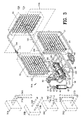
- FIG. 10 is an isometric view of the universal heat engine of the present invention.
- FIG. 11 is a side view of the universal heat engine of FIG. 10 ;
- FIG. 12 is a sectional view along line 12 - 12 in FIG. 11 ;
- FIG. 13 is a reduced sectional view along line 13 - 13 in FIG. 11 with the universal heat engine located in a first position;
- FIG. 14 is a sectional view along line 14 - 14 in FIG. 11 ;
- FIG. 15 is a sectional view along line 15 - 15 in FIG. 11 ;
- FIG. 16 is a sectional view along line 16 - 16 in FIG. 11 ;
- FIG. 17 is a sectional view along line 17 - 17 in FIG. 11 ;
- FIG. 18 is a sectional view along line 18 - 18 in FIG. 11 ;
- FIG. 19 is a sectional view similar to FIG. 13 with the universal heat engine located in a second position;
- FIG. 20 is a sectional view similar to FIG. 14 with the universal heat engine located in a second position;
- FIG. 21 is a sectional view similar to FIG. 15 with the universal heat engine located in a second position;
- FIG. 22 is a sectional view similar to FIG. 16 with the universal heat engine located in a second position;
- FIG. 23 is a sectional view similar to FIG. 17 with the universal heat engine located in a second position;
- FIG. 24 is a sectional view similar to FIG. 18 with the universal heat engine located in a second position;
- FIG. 25 is a sectional view similar to FIG. 19 with the universal heat engine located in a third position;
- FIG. 26 is a sectional view similar to FIG. 20 with the universal heat engine located in a third position;
- FIG. 27 is a sectional view similar to FIG. 21 with the universal heat engine located in a third position;
- FIG. 28 is a sectional view similar to FIG. 22 with the universal heat engine located in a third position;
- FIG. 29 is a sectional view similar to FIG. 23 with the universal heat engine located in a third position;
- FIG. 30 is a sectional view similar to FIG. 24 with the universal heat engine located in a third position;
- FIG. 31 is a sectional view similar to FIG. 25 with the universal heat engine located in a fourth position;
- FIG. 32 is a sectional view similar to FIG. 26 with the universal heat engine located in a fourth position;
- FIG. 33 is a sectional view similar to FIG. 27 with the universal heat engine located in a fourth position;
- FIG. 34 is a sectional view similar to FIG. 28 with the universal heat engine located in a fourth position;
- FIG. 35 is a sectional view similar to FIG. 29 with the universal heat engine located in a fourth position;
- FIG. 36 is a sectional view similar to FIG. 30 with the universal heat engine located in a fourth position;
- FIG. 37 is a sectional view similar to FIG. 31 with the universal heat engine located in a fifth position;
- FIG. 38 is a sectional view similar to FIG. 32 with the universal heat engine located in a fifth position;
- FIG. 39 is a sectional view similar to FIG. 33 with the universal heat engine located in a fifth position;
- FIG. 40 is a sectional view similar to FIG. 34 with the universal heat engine located in a fifth position;
- FIG. 41 is a sectional view similar to FIG. 35 with the universal heat engine located in a fifth position;
- FIG. 42 is a sectional view similar to FIG. 36 with the universal heat engine located in a fifth position;
- FIG. 43 is an isometric view of the universal heat engine of the present invention configured for generating electric power
- FIG. 44 is a side view of the universal heat engine of FIG. 42 ;
- FIG. 45 is a sectional view along line 44 - 44 in FIG. 43 ;
- FIG. 45A is a magnified view of a portion of FIG. 45 ;
- FIG. 46 is a diagram of the universal heat engine of FIGS. 42-44 with alternate heat sources and alternate electrical loads;
- FIG. 47 is a block diagram of a portion of a control system related to the heat engine section of the universal heat engine of the present invention.
- FIG. 48 is a block diagram of a portion of a control system controlling related to the output section of the universal heat engine of the present invention.
- FIG. 49 is an isometric view of a second embodiment of the universal heat engine of the present invention connected in the mobile air conditioning system of FIG. 2 ;
- FIG. 50 is a magnified view of a portion of FIG. 49 ;
- FIG. 51 is an isometric view of the second embodiment of the universal heat engine of the present invention.
- FIG. 52 is a side view of the second embodiment of the universal heat engine of FIG. 51 ;
- FIG. 53 is a sectional view along line 53 - 53 in FIG. 52 ;
- FIG. 54 is a sectional view along line 54 - 54 in FIG. 52 ;
- FIG. 55 is a sectional view along line 55 - 55 in FIG. 52 ;
- FIG. 56 is a sectional view along line 56 - 56 in FIG. 52 ;
- FIG. 57 is a block diagram of a portion of a second embodiment of a control system related to the heat engine section of the second embodiment of the universal heat engine of the present invention.
- FIG. 58 is a block diagram of a portion of a second embodiment of a control system controlling related to the output section of the second embodiment of the universal heat engine of the present invention.
- FIG. 1 is a rear isometric view of a vehicle 10 having a passenger compartment or cab 12 having a rear wall 13 .
- the vehicle 10 is shown as a class 8 truck tractor but it should be understood that the vehicle contemplated in this specification includes land vehicles and sea vessels of every description.
- the vehicle 10 is powered by a conventional diesel engine 14 receiving diesel fuel from fuel tanks 16 and 18 .
- the diesel engine 14 includes a cooling system 20 in which a cooling liquid 22 is circulated through the diesel engine 14 to be cooled by a conventional radiator (not shown).
- a heater 24 is connected to cooling system 20 for heating the passenger compartment 12 in a conventional manner. The heater 24 provides heat in the passenger compartment 12 during operation of the diesel engine 14 .
- An air conditioning system 26 is powered by the diesel engine 14 in a conventional manner.
- the air conditioning system 26 provides air conditioning to the passenger compartment 12 during operation of the diesel engine 14 .
- the heater 24 and the air conditioning system 26 operate to maintain a suitable temperature for the passenger compartment 12 during the operation of the diesel engine 14 .
- the heater 24 and the air conditioning system 26 do not operate during a period of non-operation of the diesel engine 14 .
- Anti-idling regulations restrict the operation of a diesel engine 14 of a vehicle 10 during periods of non-road travel.
- the present invention incorporates a mobile heater system 30 and a vapor generator 40 as well as a mobile air conditioning system 50 to provide suitable temperature for the passenger compartment 12 during periods of non-operation of the diesel engine 14 .
- the mobile air conditioning system 50 comprises an engine condenser 51 and an output condenser 52 located outside of the passenger compartment or cab 12 of the vehicle 10 .
- An output evaporator 53 is located within the passenger compartment or cab 12 of vehicle 10 .
- the engine condenser 51 and output condenser 52 are mounted within a mobile air conditioning module 54 secured to the rear wall 13 of the passenger compartment or cab 12 of the vehicle 10 .
- the engine condenser 51 and the output condenser 52 are angularly mounted on opposed sides of the mobile air conditioning module 54 for ensuring that the mobile air-conditioning system 50 will not interfere with the turning of the vehicle 10 .
- a thermostat 56 provides a temperature input to the mobile heater system 30 . and the mobile air conditioning system 50 .
- the universal heat engine 60 of the present invention is located within the mobile air conditioning module 54 for powering the mobile air-conditioning system 50 during non-operation of the diesel engine 14 .
- the mobile air-conditioning system 50 provides air conditioning to the passenger compartment 12 in compliance with anti-idling regulations.
- FIG. 2 is a detailed isometric view of the mobile heater system 30 as well as a mobile air conditioning system 50 of FIG. 1 .
- the mobile heater system 30 provides heat for the passenger compartment 12 during periods of non-operation of the diesel engine 14 as well as providing an input heat source to the mobile air conditioning system 50 .
- the mobile heater system 30 comprises a hydronic heater 31 having a diesel fuel input 32 and an air input 33 .
- a diesel burner 34 is located within the hydronic heater 31 for burning diesel fuel from the diesel fuel input 32 . Vapors from the burnt diesel fuel are expelled through a diesel exhaust 35 .
- the hydronic heater 31 includes a liquid input 36 and a liquid output 37 with a liquid pump 38 located therebetween.
- the hydronic heater 31 heats a liquid entering the liquid input 36 and discharges in the liquid from the liquid output 37 through the operation of the liquid pump 38 .
- the hydronic heater 31 provides heated liquid by burning diesel fuel during non-operation of the diesel engine 14 .
- the mobile heater system 30 is connected to a. vapor generator 40 .
- the liquid input 36 and the liquid output 37 of the hydronic heater 31 are connected to a primary liquid input 41 and a primary liquid output 42 of the vapor generator 40 .
- the heated liquid flowing through the primary liquid input and output 41 and 42 exchanges heat with a fluid flowing between a secondary liquid input 43 and a secondary liquid output 44 .
- FIGS. 4-7 A more detailed explanation of the vapor generator 40 appears hereinafter with reference to FIGS. 4-7 .
- the vapor generator 40 functions as a vapor source having a high pressure vapor supply 44 and a low pressure vapor return 43 .
- the mobile heater system 30 includes an optional cooling system coupling 70 .
- the cooling system coupling 70 includes a liquid input 71 and a liquid output 72 connecting the cooling system 20 of the diesel engine 14 to the vapor generator 40 .
- An input valve 73 and an output valve 74 select an input to the vapor generator 40 between the hydronic heater 31 and the cooling system 20 of the diesel engine 14 .
- Heated liquid from the hydronic heater 31 is used during non-operation of the diesel engine 14 whereas heated liquid from the cooling system 20 of the diesel engine 14 may be used to supplement or replace the conventional air-conditioning system 26 during operation of the vehicle 10 .
- FIG. 3 is an isometric view similar to FIG. 2 illustrating an alternate air conditioning system 50 A incorporating the universal heat engine 60 of the present invention.
- the alternate air conditioning system 50 A may be installed on virtually any type of structure 10 A lacking the diesel engine 14 found in the vehicle 10 .
- the structure 10 A may include a static structure such as a home, building or the like.
- the structure 10 A may include a mobile structure lacking the diesel engine 14 or electricity such as portable office, shipping container, a refrigerated compartment or the like.
- FIG. 3 illustrates is various examples of sources of heat to produce a differential in liquid temperature for powering the universal heat engine 60 of the present invention.
- a heat source 30 A is a representative of a burner for burning a petroleum product such as natural gas, propane and the like.
- a heat source 30 B is a representative of a geothermal heat source.
- a heat source 30 C is a representative of a solar heat source.
- a heat source 30 D is a representative of a byproduct heat source. It should be appreciated by those skilled in the art that the heat source for powering the universal heat engine 60 of the present invention should not be limited to the specific alternate examples of sources of heat set forth therein. The remainder of the apparatus of FIG. 3 is identical to FIG. 2 .
- FIGS. 4-7 are enlarged views of the vapor generator 40 of FIGS. 2 and 3 .
- Heated liquid enters into the primary liquid, input 41 and passes adjacent to a core 46 prior to exiting from the primary liquid output 42 .
- the fluid enters the secondary liquid input 43 and passes through a lumen 47 within the core 46 to exit from the secondary vapor output 44 .
- a helical surface fin 48 is helically wound about the core 46 to increase the surface area of the core 46 for increasing the transfer of heat between the liquid entering the primary liquid input 41 and the fluid exiting the secondary vapor output 44 .
- the vapor generator 40 functions as a vapor source having a high pressure vapor supply 44 and a low pressure vapor return 43 .
- FIG. 8 is an enlarged view of a portion of FIG. 2 illustrating the universal heat engine 60 in greater detail.
- An engine section input system 80 interconnects the vapor generator 40 with the universal heat engine 60 .
- An engine section output system 90 interconnects the universal heat engine 60 the engine condenser 51 .
- the universal heat engine 60 comprises an engine section 100 and an output section 150 .
- the universal heat engine 60 further comprises valve assemblies including an engine section valve assembly 110 , a central valve assembly 120 and an output section valve assembly 160 .
- the engine section input system 80 comprises a first and a second engine section input 81 and 82 connected to the engine section 100 of the universal heat engine 60 .
- the first and second engine section input 81 and 82 are connected to the engine valve assembly 110 and the central valve assembly 120 , respectively, of the universal heat engine 60 .
- the engine section output system 90 comprises a first and a second engine section output 91 and 92 connected to the engine condenser 51 by conduit 93 .
- the first and second engine section output 91 and 92 are connected to the engine valve assembly 110 and the central valve assembly 120 , respectively, of the universal heat engine 60 .
- Fluid is returned from the engine condenser 51 through conduit 94 , condensate pump 95 and conduit 96 to the fluid input 43 of the vapor generator 40 .
- An output section output system 180 comprises a first and a second output section output 181 and 182 connected to the output section 150 of the universal heat engine 60 .
- the first and second output section outputs 181 and 182 are connected to the central valve assembly 120 and the output valve assembly 160 , respectively, of the universal heat engine 60 .
- the first and second output section outputs 181 and 182 are connected through conduit 183 to the output condenser 52 as best shown in FIG. 2 .
- the output condenser 52 is connected through conduit 184 to the output evaporator 53 .
- a metering device 185 is interposed in conduit 184 between the output condenser 52 and the output evaporator 53 .
- An output section input system 190 comprises a first and a second output section input 191 and 192 connected to the output section 150 of the universal heat engine 60 .
- the first and second output section input 191 and 192 are connected to the central valve assembly 120 and the output valve assembly 160 , respectively, of the universal heat engine 60 .
- the first and second output section input 191 and 192 are connected through conduit 193 to the output evaporator 53
- FIG. 9 is a magnified view of a portion of FIG. 8 illustrating a valve actuator system 200 for the universal heat engine 60 .
- the valve actuator system 200 comprises a shuttle valve 202 operated by a valve actuator 204 .
- the valve actuator 204 is connected by connectors 206 and 208 to a logic board shown in FIG. 47 as will be described in greater detail hereinafter.
- the valve actuator 204 moves the shuttle valve 202 between a first position and a second position (not shown).
- the valve actuator 204 is a solenoid operated by the valve control 206 .
- a high pressure supply line 210 is connected to the engine section input system 80 whereas a low pressure supply line 220 is connected to the engine section output system 90 .
- Supply lines 211 and 212 connect the shuttle valve 202 to the engine valve assembly 110 and the central valve assembly 120 , respectively.
- supply lines 221 and 222 connect the shuttle valve 202 to the engine valve assembly 110 and the central valve assembly 120 , respectively.
- the shuttle valve provides high and low fluid pressure to supply lines 211 and 221 when the shuttle valve in the first position (not shown) and provide low and high fluid pressure to supply lines 211 and 221 when the shuttle valve in the second position (not shown).
- the valve actuator system 200 operates the universal heat engine 60 as will be described in greater detail hereinafter.
- An engine section sensor 231 and an output section sensor 232 are located in the engine valve assembly 110 and the output valve assembly 160 , respectively.
- the engine section sensor 231 and the output section sensor 232 sense the position of the engine piston 106 and the output piston 156 .
- Connectors 233 and 234 connect the engine section sensor 231 and the output section sensor 232 to the logic board shown in FIG. 47 .
- FIGS. 10-12 are various views of the universal heat engine 60 of the present invention.
- the universal heat engine 60 of the present invention is an improvement of U.S. Pat. Nos. 5,275,014, 6,739,139, 7,003,964 and 7,207,188 to Solomon which are incorporated by reference as if fully set forth herein.
- the engine section 100 of the universal heat engine 60 extends between a distal end 101 and a proximal end 102 .
- the distal end 101 is sealed to the engine valve assembly 110 .
- the proximal end 102 is sealed to the central valve assembly 120 .
- the engine section 100 is secured to the engine valve assembly 110 and the central valve assembly 120 by fasteners 103 threaded into the central valve assembly 120 .
- the engine section 100 defines a bore 105 .
- An engine piston 106 is located within the bore 105 for reciprocal movement therein.
- the engine piston 106 includes a through aperture 107 defining shoulders 108 and 109 .
- the output section 150 of the universal heat engine 60 extends between a distal end 151 and a proximal end 152 .
- the distal end 151 is sealed to the output section about assembly 160 whereas the proximal end 152 is sealed to the central valve assembly 120 .
- the output section 150 is secured to the output section valve assembly 160 and the central valve assembly 120 by fasteners 153 threaded into the central valve assembly 120 .
- the output section 151 defines a bore 155 .
- An output piston 156 is located within the bore 155 for reciprocal movement therein.
- the output piston 156 includes a through aperture 157 defining shoulders 158 and 159 .
- a connecting rod 140 interconnects the engine piston 106 to the output piston 156 through an engine coupling 130 and an output coupling 170 .
- the connecting rod 140 includes an engine spherical bearing 141 and an output spherical bearing 142 .
- the connecting rod 140 extends through a central aperture 121 in the central valve assembly 120 .
- a seal 122 is provided for sealing the engine bore 105 from the output bore 155 .
- the shaft 140 may be coated with a resilience polymeric material such as Teflon or the like.
- the engine coupling 130 including a coupling shoulder 131 is received within the aperture 107 of the piston 106 with a coupling shoulder 131 engaging with the shoulder 108 of the piston 106 .
- the engine coupling 130 defines a bearing receiver 132 for receiving the spherical bearing 141 of the connecting rod 140 .
- a bearing pin 133 secures the spherical bearing 141 to the engine coupling 130 . It should be understood at the bearing pin 133 secures the spherical bearing 141 to the engine coupling 130 prior to the engine coupling 130 being inserted within the aperture 107 of the engine piston 106 .
- An engine retainer 135 is inserted from the opposite side of the engine piston 106 with an engine retainer shoulder 136 engaging with the shoulder 109 of the engine piston 106 .
- the engine retainer 135 is secured to the engine coupling 130 through a threaded engagement 137 .
- the threaded engagement 137 ensures that the engine coupling 130 and the engine retainer 135 are fixed to the engine piston 106 .
- the engine retainer 135 supports a magnet 138 for cooperating with the sensor 231 for sensing the position of the engine piston 106 within the engine bore 105 .
- the output coupling 170 including a coupling shoulder 171 is received within the aperture 157 of the piston 156 with a coupling shoulder 171 engaging with the shoulder 158 of the piston 156 .
- the output coupling 170 defines a bearing receiver 172 for receiving the spherical bearing 142 of the connecting rod 140 .
- a bearing pin 173 secures the spherical bearing 142 to the output coupling 170 .
- An output retainer 175 is inserted from the opposite side of the output piston 156 with an output retainer shoulder 176 engaging with the shoulder 159 of the output piston 156 .
- the output retainer 175 is secured to the output coupling 170 through a threaded engagement 177 .
- the threaded engagement 177 ensures that the output coupling 170 and the output retainer 175 are fixed to the output piston 156 .
- the output retainer 175 supports a magnet 178 for cooperating with the sensor 232 for sensing the position of the output piston 156 within the output bore 155 .
- FIGS. 13-18 are various views of the universal heat engine 60 of the present invention with the universal heat engine 60 located in a first position.
- the engine piston 106 and the output piston 156 are disposed in the maximum right position.
- FIGS. 14 and 15 are sectional views illustrating the engine valve assembly 110 .
- the engine valve assembly 110 includes a valve bore 113 slidably receiving a valve 114 .
- the shuttle valve 114 is substantially cylindrical having a region of reduced area defining a shuttle valve flow region 115 .
- a threaded cap 116 retains the shuttle valve within the valve bore 113 .
- the supply lines 211 and 221 communicate with opposite ends of the valve bore 113 . A differential in fluid pressure between the supply lines 211 and 221 will move the shuttle valve 114 within the valve bore 113 .
- FIGS. 16-18 are sectional views illustrating the central valve assembly 120 .
- the central valve assembly 120 includes a valve bore 123 slidably receiving a shuttle valve 124 .
- the shuttle valve 124 is substantially cylindrical having a region of reduced area defining a shuttle valve flow region 125 .
- a threaded cap 126 retains the shuttle valve within the valve bore 123 .
- the supply lines 212 and 222 communicate with opposite ends of the valve bore 123 . A differential in fluid pressure between the supply lines 212 and 222 will move the shuttle valve 124 within the valve bore 123 .
- the shuttle valves 114 and 124 control fluid pressure of a first fluid directed to the engine section 100 of the universal heat engine 60 .
- the first fluid flows in a closed path between the engine section 100 , the engine condenser 51 and a vapor generator 40 .
- Control of the fluid pressure of the first fluid to the engine section 100 results in reciprocation of the engine piston 106 and the output piston 156 within the bores 105 and 155 respectively.
- FIGS. 17 and 18 are sectional views illustrating reed valves 127 and 128 located within the central valve assembly 120 .
- the reed valve 127 is located in proximity to the first output section output 181 whereas the reed valve 128 is located in proximity to the second output section input 192 .
- the reed valves 127 and 128 are one-way valves operated by applied pressure to the surface of the reed valves 127 and 128 .
- FIG. 13 is a sectional view illustrating reed valves 161 and 162 located within the output section valve assembly 160 .
- the reed valve 161 is located in proximity to the first output section input 191 whereas the reed valve 162 is located in proximity to the second output section output 182 .
- a second fluid flows in a closed path between the output section 150 , the output condenser 52 and the output evaporator 53 .
- the reed valve 127 and 128 in combination with the reed valves 161 and 162 control the direction of flow of the second fluid in vapor form from the output section 150 of the universal heat engine 60 .
- the fluid flow of the second fluid from the output section 150 through the output condenser 52 , the metering device 185 and the output evaporator 53 results in air conditioning or refrigeration of a desire space.
- the second fluid operates in accordance with the Carnot cycle as should be well known to those skilled in the art.
- FIGS. 19-24 illustrate the universal heat engine 60 located in a second position.
- the engine piston 106 and the output piston 156 are shown moved to the left from the maximum right position.
- the first fluid flows into the second engine input 82 to move the engine piston 106 to the left in FIG. 19 .
- the first fluid flows from the first engine output 91 as the engine piston 106 moves to the left in FIG. 19 .
- the second fluid flows from the first output section output 181 through the reed valve 127 to flow into the output condenser 52 .
- the second fluid flows from the output evaporator 53 into the first output section input 191 through reed valve 161 .
- FIG. 25-30 illustrate the universal heat engine 60 located in a third position.
- the engine piston 106 and the output piston 156 are disposed in the maximum left position.
- Fluid pressure of the first fluid from supply line 221 moves the shuttle valve 114 to the position shown in FIGS. 26 and 27 .
- Fluid pressure of the first fluid from supply line 222 moves the shuttle valve 124 to the position shown in FIGS. 28 and 29 .
- the position of the shuttle valve 114 enables the first fluid to enter the first engine input 81 to urge the engine piston 106 toward the right in FIG. 25 .
- the position of the shuttle valve 124 enables the first fluid to exit from the second engine output 92 as the engine piston 106 moves toward the right in FIG. 25 .
- FIG. 31-36 illustrate the universal heat engine 60 located in a fourth position.
- the engine piston 106 and the output piston 156 are shown moved to the right from the maximum left position.
- the first fluid flows into the first engine input 81 to move the engine piston 106 to the right in FIG. 31 .
- the first fluid flows from the second engine output 92 as the engine piston 106 moves to the right in FIG. 31 .
- the second fluid flows from the second output section output 182 through the reed valve 162 to flow into the output condenser 52 .
- the second fluid flows from the output evaporator 53 into the second output section input 192 through reed valve 128 .
- FIG. 37-42 illustrate the universal heat engine 60 located in a fifth position.
- the engine piston 106 and the output piston 156 are disposed in the maximum right position similar to FIGS. 13-18 .
- Fluid pressure of the first fluid from supply line 211 is applied to move the shuttle valve 114 into the position shown in FIGS. 20 and 21 .
- Fluid pressure of the first fluid from supply line 212 is applied to move the shuttle valve 124 to the position shown in FIGS. 22 and 23 .
- the position of the shuttle valve 114 enables the first fluid to enter the second engine input 82 to urge the engine piston 106 toward the left in FIG. 37 .
- the position of the shuttle valve 124 enables the first fluid to exit from the first engine output 91 as the engine piston 106 moves toward the left in FIG. 37 .
- a heated first fluid is provided to the engine section input system 80 including the first engine input 81 and the second engine input 82 .
- the shuttle valves 114 and 124 alternately direct the heated first fluid to opposite sides of the engine piston 106 .
- the first fluid is discharged by the engine section output system 90 including the first and second engine outputs 91 and 92 .
- the discharged first fluid is cooled by the engine condenser 51 thereby producing a differential in fluid temperature to power the universal heat engine 60 .
- Reciprocal operations of the engine piston 106 results in reciprocal movement of the output piston 156 .
- the second fluid is alternately discharged by the output section output system 180 including first and second output section outputs 81 and 82 .
- the compressed second fluid is directed to the output condenser 52 for cooling the compressed second fluid.
- the compressed second fluid is passed to the metering device 185 to cool the evaporator 53 .
- FIGS. 43-45 are various views of the universal heat engine 60 E of the present invention configured for generating electric power.
- the universal heat engine 60 E includes an engine section 100 E and an output section 150 E.
- the engine section 100 E includes a bore 105 E with an engine piston 106 E slidably disposed within the bore 105 E.
- the engine section 100 E is identical to the engine section 100 shown in FIGS. 8-42 .
- the output section 150 E includes a bore 155 E with an output piston 156 E slidably disposed within the bore 155 E.
- the output piston 156 E is connected to the engine piston 106 E by connecting rod 140 E in a manner similar to FIGS. 8-42 .
- the output piston 156 E includes a permanent magnet 240 E for cooperating with an electrical coil 242 E wound about the output section 150 E. Reciprocal movement of the engine piston 106 E results in reciprocal movement of the permanent magnet 240 E within the electrical coil 242 E for generating electrical current.
- FIG. 46 is a diagram of the universal heat engine 60 E of FIGS. 43-45 with alternate heat sources 30 E and alternate electrical loads 250 E.
- the alternate heat sources 30 E include a solar heat source 31 E, a geothermal heat source 32 E, a natural gas or propane heat source 33 E or any other miscellaneous heat source 34 E.
- Electrical energy produced by the universal heat engine 60 E may be used or stored in various ways.
- alternate electrical loads 250 E include battery storage 251 E, capacitor storage 252 E, direct electrical use 253 E and a grid tie inverter 254 to transfer electrical power to the electrical grid.
- FIGS. 47 and 48 are block diagrams of a portion 310 of a control system 300 related to the heat engine section 100 and a portion 320 of a control system 300 related to the output section of the universal heat engine 60 of the present invention.
- FIG. 49 is an isometric view of a second embodiment of the universal heat engine 60 F of the present invention connected in the mobile air conditioning system 50 of FIG. 2 .
- the mobile air conditioning system 50 is fully explained with reference to FIG. 2 .
- the second embodiment of the universal heat engine 60 F replaces the universal heat engine 60 shown in FIGS. 2-42 .
- FIG. 50 is an enlarged view of a portion of FIG. 49 illustrating the universal heat engine 60 F in greater detail.
- An engine section input system 80 interconnects the vapor generator 40 with the universal heat engine 60 F.
- the engine section output system 90 interconnects the universal heat engine 60 F the engine condenser 51 .
- the universal heat engine 60 F comprises an engine section 100 F and an output section 150 F.
- the universal heat engine 60 F further comprises valve assemblies including an engine section valve assembly 110 F, a central valve assembly 120 F and an output section valve assembly 160 F.
- the engine section input system 80 comprises the first and second engine section inputs 81 and 82 connected to the engine section 100 F of the universal heat engine 60 F.
- the first and second engine section inputs 81 and 82 are connected to the engine valve assembly 110 F and the central valve assembly 120 F, respectively.
- the engine section output system 90 comprises the first and second engine section outputs 91 and 92 connected to the engine condenser 51 by conduit 93 .
- the first and second engine section outputs 91 and 92 are connected to the engine valve assembly 110 F and the central valve assembly 120 F, respectively.
- Fluid is returned from the engine condenser 51 through conduit 94 , condensate pump 95 and conduit 96 to the fluid input 43 of the vapor generator 40 .
- the output section output system 180 comprises the first and second output section outputs 181 and 182 connected to the output section 150 F of the universal heat engine 60 F.
- the first and second output section outputs 181 and 182 are connected to the central valve assembly 120 F and the output valve assembly 160 F, respectively.
- the first and second output section outputs 181 and 182 are connected through conduit 183 to the output condenser 52 .
- the output condenser 52 is connected through conduit 184 to the output evaporator 53 .
- the output section input system 190 comprises the first and second output section inputs 191 and 192 connected to the output section 150 F of the universal heat engine 60 F.
- the first and second output section inputs 191 and 192 are connected to the central valve assembly 120 F and the output valve assembly 160 F, respectively.
- the first and second output section inputs 191 and 192 are connected through conduit 193 to the output evaporator 53
- the valve actuator system 200 comprises the shuttle valve 202 operated by the valve actuator 204 .
- the valve actuator 204 is connected by connectors 206 and 208 to a second embodiment of a logic board shown in FIG. 57 .
- the valve actuator 204 move the shuttle valve 202 between the first position and the second position as previously described.
- the high pressure supply line 210 is connected to the engine section input system 80 whereas the low pressure supply line 220 is connected to the engine section output system 90 .
- Supply lines 211 and 212 connect the shuttle valve 202 to the engine valve assembly 110 F and the central valve assembly 120 F, respectively.
- supply lines 221 and 222 connect the shuttle valve 202 to the engine valve assembly 110 F and the central valve assembly 120 F, respectively.
- the shuttle valve provides high and low fluid pressure to supply lines 211 and 221 when the shuttle valve 202 in the first position and provide low and high fluid pressure to supply lines 211 and 221 when the shuttle valve 202 in the second position as previously described.
- the engine section sensor 231 and the output section sensor 232 are located in the engine valve assembly 110 F and the output valve assembly 160 F, respectively.
- the engine section sensor 231 and the output section sensor 232 sense the position of the engine piston 106 F and the output piston 156 F.
- Connectors 233 and 234 connect the engine section sensor 231 and the output section sensor 232 to the second embodiment of the logic board shown in FIG. 58 .
- FIGS. 51-56 illustrate various views of the second embodiment of the universal heat engine 60 F of the present invention. Similar parts with the universal heat engine 60 shown in FIGS. 2-42 are labeled with similar reference numeral followed by an F.
- the engine section 100 F of the universal heat engine 60 F extends between a distal end 101 F and a proximal end 102 F.
- the distal end 101 F is sealed to the engine valve assembly 110 F.
- the proximal end 102 F is sealed to the central valve assembly 120 F.
- the engine section 100 F is secured to the engine valve assembly 110 F and the central valve assembly 120 F by fasteners 103 F threaded into the central valve assembly 120 F.
- the engine section 100 F defines a bore 105 F.
- An engine piston 106 F is located within the bore 105 F for reciprocal movement therein.
- the engine piston 106 F includes a through aperture 107 F defining shoulders 108 F and 109 F.
- the output section 150 F of the universal heat engine 60 F extends between a distal end 151 F and a proximal end 152 F.
- the distal end 151 F is sealed to the output section about assembly 160 F whereas the proximal end 152 F is sealed to the central valve assembly 120 F.
- the output section 150 F is secured to the output section valve assembly 160 F and the central valve assembly 120 F by fasteners 153 F threaded into the central valve assembly 120 F.
- the output section 151 F defines a bore 155 F.
- An output piston 156 F is located within the bore 155 F for reciprocal movement therein.
- the output piston 156 F includes a through aperture 157 F defining shoulders 158 F and 159 F.
- a connecting rod 140 F interconnects the engine piston 106 F to the output piston 156 F through an engine coupling 130 F and an output coupling 170 F.
- the connecting rod 140 F includes an engine spherical bearing 141 F and an output spherical bearing 142 F.
- the connecting rod 140 F extends through a central aperture 121 F in the central valve assembly 120 F.
- a seal 122 F is provided for sealing the engine bore 105 F from the output bore 155 F.
- the connecting rod 140 F extends through a linear bearing 140 F.
- the engine coupling 130 F including a coupling shoulder 131 F is received within the aperture 107 F of the piston 106 F with a coupling shoulder 131 F engaging with the shoulder 108 F of the piston 106 F.
- the engine coupling 130 F defines a bearing receiver 132 F for receiving the spherical bearing 141 F of the connecting rod 140 F.
- a bearing pin 133 F secures the spherical bearing 141 F to the engine coupling 130 F.
- An engine retainer 135 F is inserted from the opposite side of the engine piston 106 F with an engine retainer shoulder 136 F engaging with the shoulder 109 F of the engine piston 106 F.
- the engine retainer 135 F is secured to the engine coupling 130 F through a threaded engagement 137 F.
- the engine retainer 135 F supports a magnet 138 F for cooperating with the sensor 231 for sensing the position of the engine piston 106 F within the engine bore 105 F.
- the output coupling 170 F including a coupling shoulder 171 F is received within the aperture 157 F of the piston 156 F with a coupling shoulder 171 F engaging with the shoulder 158 F of the piston 156 F.
- the output coupling 170 F defines a bearing receiver 172 F for receiving the spherical bearing 142 F of the connecting rod 140 F.
- a bearing pin 173 F secures the spherical bearing 142 F to the output coupling 170 F.
- An output retainer 175 F is inserted from the opposite side of the output piston 156 F with an output retainer shoulder 176 F engaging with the shoulder 159 F of the output piston 156 F.
- the output retainer 175 F is secured to the output coupling 170 F through a threaded engagement 177 F.
- the output retainer 175 F supports a magnet 178 F for cooperating with the sensor 232 F for sensing the position of the output piston 156 F within the output bore 155 F.
- FIG. 54 is a sectional view illustrating the engine valve assembly 110 F.
- the engine valve assembly 110 F includes a valve bore 113 F slidably receiving a shuttle valve 114 F.
- the shuttle valve 114 F is substantially cylindrical having a region of reduced area defining a shuttle valve flow region 115 F. Threaded caps 116 F retain the shuttle valve 114 F within the valve bore 113 F.
- the supply lines 211 and 221 communicate with opposite ends of the valve bore 113 F. A differential in fluid pressure between the supply lines 211 and 221 will move the shuttle valve 114 F within the valve bore 113 F.
- FIG. 55 is a sectional view illustrating the central valve assembly 120 F.
- the central valve assembly 120 F includes a valve bore 123 F slidably receiving a shuttle valve 124 F.
- the shuttle valve 124 F is substantially cylindrical having a region of reduced area defining a shuttle valve flow region 125 F. Threaded caps 126 F retain the shuttle valve 124 F within the valve bore 123 F.
- the supply lines 212 and 222 communicate with opposite ends of the valve bore 123 F. A differential in fluid pressure between the supply lines 212 and 222 will move the shuttle valve 124 F within the valve bore 123 F.
- the shuttle valves 114 F and 124 F control fluid pressure of a first fluid directed to the engine section 100 F of the universal heat engine 60 F.
- the first fluid flows in the closed path between the engine section 100 F, the engine condenser 51 and the vapor generator 40 .
- Control of the fluid pressure of the first fluid to the engine section 100 F results in reciprocation of the engine piston 106 F and the output piston 156 F within the bores 105 F and 155 F respectively.
- the second embodiment of the universal heat engine 60 F utilizes check valves 127 D and 128 D and check valves 161 F and 162 F instead of the reed valves 127 and 128 and the reed valves 161 and 162 of the universal heat engine 60 of FIGS. 2-42 .
- the check valves 127 D and 128 D and check valves 161 F and 162 F are spring loaded check valves.
- the check valve 127 D is located in proximity to the first output section output 181 whereas the check valve 128 D is located in proximity to the second output section input 192 .
- the check valve 161 F is located in proximity to the first output section input 191 whereas the check valve 162 F is located in proximity to the second output section output 182 .
- the second embodiment of the universal heat engine 60 F of the present invention shown in FIGS. 49-56 operates in a manner similar to the operation of the universal heat engine 60 of FIGS. 2-42
- FIGS. 57 and 58 are block diagrams of a portion 310 F of a control system 300 F related to the heat engine section 100 F and a portion 320 F of a control system 300 F related to the output section of the second embodiment of the universal heat engine 60 F of the present invention.
Abstract
Description
Claims (28)
Priority Applications (1)
| Application Number | Priority Date | Filing Date | Title |
|---|---|---|---|
| US13/374,060 US8844291B2 (en) | 2010-12-10 | 2011-12-09 | Universal heat engine |
Applications Claiming Priority (2)
| Application Number | Priority Date | Filing Date | Title |
|---|---|---|---|
| US45933110P | 2010-12-10 | 2010-12-10 | |
| US13/374,060 US8844291B2 (en) | 2010-12-10 | 2011-12-09 | Universal heat engine |
Publications (2)
| Publication Number | Publication Date |
|---|---|
| US20120317980A1 US20120317980A1 (en) | 2012-12-20 |
| US8844291B2 true US8844291B2 (en) | 2014-09-30 |
Family
ID=46207433
Family Applications (1)
| Application Number | Title | Priority Date | Filing Date |
|---|---|---|---|
| US13/374,060 Active 2031-12-31 US8844291B2 (en) | 2010-12-10 | 2011-12-09 | Universal heat engine |
Country Status (7)
| Country | Link |
|---|---|
| US (1) | US8844291B2 (en) |
| EP (1) | EP2649386B1 (en) |
| CN (1) | CN103492818B (en) |
| AU (1) | AU2011338995B2 (en) |
| BR (1) | BR112013014453B1 (en) |
| MX (1) | MX2013006496A (en) |
| WO (1) | WO2012078195A1 (en) |
Cited By (1)
| Publication number | Priority date | Publication date | Assignee | Title |
|---|---|---|---|---|
| US20160222833A1 (en) * | 2015-02-03 | 2016-08-04 | Borgwarner Inc. | Waste heat recovery system layout and packaging strategy |
Families Citing this family (6)
| Publication number | Priority date | Publication date | Assignee | Title |
|---|---|---|---|---|
| BR112013014453B1 (en) | 2010-12-10 | 2021-03-23 | Vaporgenics,Inc. | UNIVERSAL THERMAL ENGINE |
| EP2909453A2 (en) * | 2012-10-17 | 2015-08-26 | Norgren Limited | Vehicle waste heat recovery system |
| US11137177B1 (en) | 2019-03-16 | 2021-10-05 | Vaporgemics, Inc | Internal return pump |
| WO2021001027A1 (en) * | 2019-07-02 | 2021-01-07 | Volvo Truck Corporation | A fuel gas system for a vehicle |
| US11125386B2 (en) * | 2019-07-15 | 2021-09-21 | Consolidated Edison Company Of New York, Inc. | Sensor for steam trap and method of operation |
| EP3839221A1 (en) * | 2019-12-18 | 2021-06-23 | Nederlandse Organisatie voor toegepast- natuurwetenschappelijk Onderzoek TNO | Heavy-duty vehicle comprising a combustion engine |
Citations (109)
| Publication number | Priority date | Publication date | Assignee | Title |
|---|---|---|---|---|
| US1870848A (en) * | 1930-03-15 | 1932-08-09 | Westinghouse Air Brake Co | Fluid compressor controlling valve |
| US3129645A (en) * | 1962-05-02 | 1964-04-21 | Double A Prod Co | Electrically modulated fluid valve |
| US3662553A (en) * | 1970-12-31 | 1972-05-16 | Steam Power Systems Inc | Valve actuation system for steam engine |
| US3823573A (en) * | 1973-03-16 | 1974-07-16 | V Cassady | Automotive air conditioning apparatus |
| US3988901A (en) * | 1975-02-18 | 1976-11-02 | Scientific-Atlanta, Inc. | Dual loop heat pump system |
| US4018581A (en) * | 1974-12-17 | 1977-04-19 | John Denis Ruff | Solar heating system |
| US4406306A (en) * | 1982-03-19 | 1983-09-27 | Eaton Corporation | Heat pump switchover valve |
| US4666373A (en) | 1986-03-20 | 1987-05-19 | Eiichi Sugiura | Impeller for rotary fluid machine |
| US4823560A (en) * | 1988-05-27 | 1989-04-25 | E Squared Inc. | Refrigeration system employing refrigerant operated dual purpose pump |
| US5129236A (en) | 1990-09-06 | 1992-07-14 | Solomon Fred D | Heat pump system |
| US5282366A (en) * | 1990-11-26 | 1994-02-01 | National Refrigeration Products, Inc. | Transportable refrigerant transfer unit and methods of using the same |
| US5365908A (en) | 1991-10-15 | 1994-11-22 | Yamaha Hatsudoki Kabushiki Kaisha | Burning control system for engine |
| US5509274A (en) | 1992-01-16 | 1996-04-23 | Applied Power Technologies Incorporated | High efficiency heat pump system |
| US5674053A (en) * | 1994-04-01 | 1997-10-07 | Paul; Marius A. | High pressure compressor with controlled cooling during the compression phase |
| US5725365A (en) | 1995-12-12 | 1998-03-10 | Solomon; Fred D. | Rolling diaphragm seal arrangement for a submersible pump system |
| US6138649A (en) | 1997-09-22 | 2000-10-31 | Southwest Research Institute | Fast acting exhaust gas recirculation system |
| US6167703B1 (en) | 1998-03-28 | 2001-01-02 | Daimlerchrysler Ag | Internal combustion engine with VTG supercharger |
| US6467269B1 (en) | 2001-12-20 | 2002-10-22 | Caterpillar Inc | Altitude compensation for turbocharger wastegate |
| US6532916B2 (en) * | 2001-03-28 | 2003-03-18 | Jack L. Kerrebrock | Opposed piston linearly oscillating power unit |
| US6541875B1 (en) * | 2000-05-17 | 2003-04-01 | Caterpillar Inc | Free piston engine with electrical power output |
| US6546713B1 (en) | 1997-12-15 | 2003-04-15 | Hitachi, Ltd. | Gas turbine for power generation, and combined power generation system |
| US6554088B2 (en) | 1998-09-14 | 2003-04-29 | Paice Corporation | Hybrid vehicles |
| US6625978B1 (en) | 1998-12-07 | 2003-09-30 | Ingemar Eriksson | Filter for EGR system heated by an enclosing catalyst |
| US6651432B1 (en) | 2002-08-08 | 2003-11-25 | The United States Of America As Represented By The Administrator Of The Environmental Protection Agency | Controlled temperature combustion engine |
| US6732723B2 (en) | 2002-04-04 | 2004-05-11 | Ford Global Technologies, Llc | Method and system for controlling EGR rate in diesel engines |
| US6739139B1 (en) | 2003-05-29 | 2004-05-25 | Fred D. Solomon | Heat pump system |
| US6896789B2 (en) | 2001-06-04 | 2005-05-24 | Canadian Hydrogen Energy Company Limited | Electrolysis cell and internal combustion engine kit comprising the same |
| US6915656B2 (en) * | 2003-07-14 | 2005-07-12 | Eco Technology Solutions, Llc | Heat pump system |
| EP1669585A2 (en) | 2004-12-10 | 2006-06-14 | LG Electronics, Inc. | Cogeneration system |
| EP1892404A2 (en) | 2006-08-07 | 2008-02-27 | United Technologies Corporation | Dual-function stirling engine system |
| US20080148731A1 (en) * | 2006-12-22 | 2008-06-26 | Yiding Cao | Heat engines |
| WO2008125827A2 (en) | 2007-04-13 | 2008-10-23 | City University | Organic rankine cycle apparatus and method |
| US20090000327A1 (en) | 2005-12-14 | 2009-01-01 | Behr Gmbh& Co.Kg | Heat Pump |
| US20090077961A1 (en) | 2007-09-24 | 2009-03-26 | Baker David M | Heat Concentrator Piston and Chamber |
| US7571699B2 (en) | 2006-03-24 | 2009-08-11 | Scuderi Group, Llc | System and method for split-cycle engine waste heat recovery |
| EP1750959B1 (en) | 2004-05-07 | 2009-09-16 | Lombardini S.r.l. | An air-conditioning system for trucks |
| US7591143B2 (en) | 2002-04-29 | 2009-09-22 | Bergstrom, Inc. | Vehicle air conditioning and heating system providing engine on and engine off operation |
| WO2009119185A1 (en) | 2008-03-27 | 2009-10-01 | いすゞ自動車株式会社 | Waste heat recovering device |
| US20090277400A1 (en) | 2008-05-06 | 2009-11-12 | Ronald David Conry | Rankine cycle heat recovery methods and devices |
| US20090277152A1 (en) | 2008-05-07 | 2009-11-12 | Ronald Steven Sutherland | Quasi-isobaric heat engine |
| WO2009139926A1 (en) | 2008-05-16 | 2009-11-19 | Potomac Energy Projects, Llc | Hybrid solar collector and geothermal system |
| EP2126483A1 (en) | 2006-12-08 | 2009-12-02 | UTC Power Corporation | Providing engine heat to an absorption chiller |
| US7629530B2 (en) | 2003-04-17 | 2009-12-08 | Toyota Jidosha Kabushiki Kaisha | Energy recovery system |
| WO2010006319A2 (en) | 2008-07-10 | 2010-01-14 | Infinia Corporation | Thermal energy storage device |
| WO2010022184A2 (en) | 2008-08-19 | 2010-02-25 | Ram Power, Inc. | Solar thermal power generation using multiple working fluids in a rankine cycle |
| WO2010024579A2 (en) | 2008-08-27 | 2010-03-04 | Chae Soo Joh | Linear solar heat generating system |
| WO2010027360A2 (en) | 2008-09-04 | 2010-03-11 | Etalim Inc. | Multiple heat engine power generation system |
| WO2010035927A1 (en) | 2008-09-23 | 2010-04-01 | 주식회사 자이벡 | Thermal energy recovery system |
| WO2010045269A2 (en) | 2008-10-13 | 2010-04-22 | Infinia Corporation | Stirling engine systems, apparatus and methods |
| EP2180171A1 (en) | 2008-10-24 | 2010-04-28 | Behr GmbH & Co. KG | System with a Rankine cycle |
| US20100101224A1 (en) | 2007-04-06 | 2010-04-29 | Junichiro Kasuya | Waste Heat Utilization Device for Internal Combustion Engine |
| US7726129B2 (en) | 2004-06-16 | 2010-06-01 | E.A. Technical Services Limited | Stirling cycle engine |
| WO2010067359A2 (en) | 2008-12-09 | 2010-06-17 | Abraham Sadeh | Closed loop solar energy system with a push-pull electric generator |
| US20100156111A1 (en) | 2008-06-01 | 2010-06-24 | John Pesce | Thermo-Electric Engine |
| US7748226B2 (en) | 2003-03-25 | 2010-07-06 | Denso Corporation | Waste heat utilizing system |
| US7765824B2 (en) | 2006-02-01 | 2010-08-03 | Paccar Inc | Vehicle interior cooling system |
| WO2010090456A2 (en) | 2009-02-04 | 2010-08-12 | Chae Soo Joh | Heat engine using solar energy |
| WO2010102874A2 (en) | 2009-03-10 | 2010-09-16 | Newcomen S.R.L. | Integrated rankine-cycle machine |
| US20100294217A1 (en) | 2008-01-21 | 2010-11-25 | Junichiro Kasuya | Waste Heat Utilization Device for Internal Combustion Engine |
| WO2010149277A2 (en) | 2009-06-22 | 2010-12-29 | Eth Zurich | Non-stationary reciprocating solar thermal heat engine driven by pulsed concentrated solar irradiation |
| WO2011005673A1 (en) | 2009-07-07 | 2011-01-13 | Global Cooling, Inc. | Gamma type free-piston stirling machine configuration |
| WO2011007197A1 (en) | 2009-07-15 | 2011-01-20 | Michael Kangwana | Lowgen low grade energy power generation system |
| WO2011017767A1 (en) | 2009-08-14 | 2011-02-17 | Gnomon Technologies Pty Ltd | Thermal energy storage apparatus, arrangement and method |
| US7891575B2 (en) | 2006-11-03 | 2011-02-22 | Sami Samuel M | Method and apparatus for thermal storage using heat pipes |
| WO2011044262A2 (en) | 2009-10-06 | 2011-04-14 | David Baker | Thermal transformer |
| WO2011048584A2 (en) | 2009-10-21 | 2011-04-28 | Artemis Energy Limited | A solar energy conversion system and method |
| WO2011053895A1 (en) | 2009-11-02 | 2011-05-05 | Ricor Solar Ltd. | Stirling engine solar concentrator system |
| WO2011054383A1 (en) | 2009-11-04 | 2011-05-12 | Aeteba Gmbh | Compact refrigerating unit |
| WO2011058832A1 (en) | 2009-11-13 | 2011-05-19 | 三菱重工業株式会社 | Engine waste heat recovery power-generating turbo system and reciprocating engine system provided therewith |
| WO2011066964A2 (en) | 2009-12-04 | 2011-06-09 | Erhard Weber | Waste heat-fed heat recovery system |
| US7975501B2 (en) | 2006-01-13 | 2011-07-12 | Lombardini S.R.L. A Socio Unico | Air conditioning system for a motor vehicle |
| US20110174006A1 (en) | 2008-08-26 | 2011-07-21 | Airbus Operations Gmbh | Zone temperature control on board an airplane by means of fuel cell waste heat |
| WO2011106859A1 (en) | 2010-03-05 | 2011-09-09 | Zulmira Teresina Iockheck | Stirling cycle energy converter |
| US20110219801A1 (en) | 2010-03-10 | 2011-09-15 | Mckenzie Craig | Solar powered compressor/pump combination |
| WO2011120132A1 (en) | 2010-04-01 | 2011-10-06 | Enermotion Inc. | A system and method for storing thermal energy as auxiliary power in a vehicle |
| US20110265501A1 (en) | 2010-04-29 | 2011-11-03 | Ari Nir | System and a method of energy recovery from low temperature sources of heat |
| US20110271674A1 (en) | 2009-01-13 | 2011-11-10 | Avl North America Inc. | Sliding vane rotary expander for waste heat recovery system |
| US20110296849A1 (en) | 2010-06-02 | 2011-12-08 | Benson Dwayne M | Integrated power, cooling, and heating apparatus utilizing waste heat recovery |
| WO2012016873A1 (en) | 2010-07-30 | 2012-02-09 | Innova Solar Energy S.R.L. | Solar radiation heat absorber for a stirling motor |
| US20120096884A1 (en) | 2010-10-25 | 2012-04-26 | Schaefer Cletus F | Solar Powered Air Conditioner, which is powered directly by solar energy with no need of conversion to electricity, hence no emissions of Carbon Dioxide |
| WO2012061812A2 (en) | 2010-11-05 | 2012-05-10 | Mack Trucks, Inc. | Thermoelectric recovery and peltier heating of engine fluids |
| US20120117986A1 (en) | 2010-11-15 | 2012-05-17 | James Peter Hammond | Solar collector and solar air conditioning system having the same |
| WO2012064208A1 (en) | 2010-11-12 | 2012-05-18 | Olpek-Garden Usługi Ogrodnicze Olpiński, Marcin | Method for converting low temperature thermal energy into high temperature thermal energy and mechanical energy and a heat pump device for such conversion |
| WO2012078195A1 (en) | 2010-12-10 | 2012-06-14 | Vaporgenics,Inc. | Universal heat engine |
| US20120180511A1 (en) | 2009-07-08 | 2012-07-19 | Colipu A/S | Energy System With A Heat Pump |
| US20120198840A1 (en) | 2009-08-12 | 2012-08-09 | Juergen Stegmaier | Device for utilizing waste heat |
| US20120216763A1 (en) | 2011-02-28 | 2012-08-30 | Cummins Intellectual Property, Inc. | Engine having integrated waste heat recovery |
| US20120247134A1 (en) | 2009-08-04 | 2012-10-04 | Echogen Power Systems, Llc | Heat pump with integral solar collector |
| WO2012140575A2 (en) | 2011-04-11 | 2012-10-18 | Deltae S.R.L. | Method for dimensioning a solar generation system, and the solar generation system obtained |
| US20120272643A1 (en) | 2011-05-01 | 2012-11-01 | Thomas Mallory Sherlock | Solar Air Conditioning Heat Pump with Minimized Dead Volume |
| US20120279243A1 (en) | 2010-01-12 | 2012-11-08 | Honda Motor Co., Ltd. | Air conditioning system for vehicle |
| US20120291433A1 (en) | 2011-05-19 | 2012-11-22 | Ning Meng | Low temperature rankine cycle solar power system with low critical temperature hfc or hc working fluid |
| WO2012159566A1 (en) | 2011-05-24 | 2012-11-29 | 武汉凯迪工程技术研究总院有限公司 | Disc-type solar stirling engine power generation device capable of operating continuously day and night |
| EP2021634B1 (en) | 2006-05-16 | 2012-12-26 | Ecoenergy Patent GmbH | Device and associated method for the conversion of heat energy into mechanical, electrical and/or thermal energy |
| US20130074489A1 (en) | 2011-09-26 | 2013-03-28 | Toyota Jidosha Kabushiki Kaisha | Stirling engine and engine system comprising stirling engine |
| US20130091884A1 (en) | 2011-10-14 | 2013-04-18 | Robert A. Hunt | Heat Powered Reciprocating Piston Engine |
| US20130104546A1 (en) | 2011-10-31 | 2013-05-02 | Dharendra Yogi Goswami | Integrated Cascading Cycle Solar Thermal Plants |
| US20130125545A1 (en) | 2010-07-13 | 2013-05-23 | Behr Gmbh & Co. Kg | System for utilizing waste heat of an internal combustion engine |
| US20130146000A1 (en) | 2011-12-09 | 2013-06-13 | Industry-University Cooperation Foundation Hanyang University Erica Campus | Heat Storage Device of Vehicle |
| EP1961599B1 (en) | 2007-02-21 | 2013-07-10 | Bergstrom, Inc. | Truck electrified engine-off air conditioning system |
| WO2013103654A1 (en) | 2012-01-04 | 2013-07-11 | Nielsen Terry R | Auxiliary power unit and heating system for a vehicle cabin |
| US8522569B2 (en) | 2009-10-27 | 2013-09-03 | Industrial Idea Partners, Inc. | Utilization of data center waste heat for heat driven engine |
| US8544270B2 (en) | 2008-10-20 | 2013-10-01 | Sanden Corporation | Waste heat recovery system of internal combustion engine |
| US20130263619A1 (en) | 2012-04-09 | 2013-10-10 | Davorin Kapich | Combustion engine waste heat powered air-conditioning system |
| US20130269343A1 (en) | 2012-04-16 | 2013-10-17 | GM Global Technology Operations LLC | Vehicle with stirling engine integrated into engine exhaust system |
| US8601988B2 (en) | 2007-07-23 | 2013-12-10 | Umc Universal Motor Corporation Gmbh | Free piston assembly and method for controlling a free piston assembly |
| US20130327042A1 (en) | 2009-02-20 | 2013-12-12 | American Thermal Power, Llc | Thermodynamic power generation system |
| US8607855B2 (en) | 2007-02-23 | 2013-12-17 | Behr Gmbh & Co. Kg | Cooling system for a motor vehicle |
| US20140020415A1 (en) | 2012-07-18 | 2014-01-23 | Peter Heyl | Heat distribution in a motor vehicle |
Family Cites Families (8)
| Publication number | Priority date | Publication date | Assignee | Title |
|---|---|---|---|---|
| US1462661A (en) * | 1921-11-12 | 1923-07-24 | Steiger & Kerr Stove & Foundry | Gas stove |
| US6092365A (en) * | 1998-02-23 | 2000-07-25 | Leidel; James A. | Heat engine |
| BG63668B1 (en) * | 1999-06-18 | 2002-08-30 | "Йордан Колев Интегрални Мотори" Командитно Дружество | System for piston engine compression and ejection |
| DE10313676A1 (en) * | 2003-03-26 | 2004-10-07 | Imi Norgren-Herion Fluidtronic Gmbh & Co. Kg | Position measuring device for fluidic cylinder-piston arrangements |
| US7284709B2 (en) * | 2003-11-07 | 2007-10-23 | Climate Energy, Llc | System and method for hydronic space heating with electrical power generation |
| US8250863B2 (en) * | 2008-04-09 | 2012-08-28 | Sustainx, Inc. | Heat exchange with compressed gas in energy-storage systems |
| US7992386B2 (en) * | 2008-11-03 | 2011-08-09 | Cyclone Power Technologies, Inc. | Waste heat engine |
| US20110221206A1 (en) * | 2010-03-11 | 2011-09-15 | Miro Milinkovic | Linear power generator with a reciprocating piston configuration |
-
2011
- 2011-12-09 BR BR112013014453-0A patent/BR112013014453B1/en not_active IP Right Cessation
- 2011-12-09 MX MX2013006496A patent/MX2013006496A/en active IP Right Grant
- 2011-12-09 EP EP11847492.3A patent/EP2649386B1/en not_active Not-in-force
- 2011-12-09 CN CN201180067245.0A patent/CN103492818B/en not_active Expired - Fee Related
- 2011-12-09 US US13/374,060 patent/US8844291B2/en active Active
- 2011-12-09 AU AU2011338995A patent/AU2011338995B2/en not_active Ceased
- 2011-12-09 WO PCT/US2011/001970 patent/WO2012078195A1/en active Application Filing
Patent Citations (120)
| Publication number | Priority date | Publication date | Assignee | Title |
|---|---|---|---|---|
| US1870848A (en) * | 1930-03-15 | 1932-08-09 | Westinghouse Air Brake Co | Fluid compressor controlling valve |
| US3129645A (en) * | 1962-05-02 | 1964-04-21 | Double A Prod Co | Electrically modulated fluid valve |
| US3662553A (en) * | 1970-12-31 | 1972-05-16 | Steam Power Systems Inc | Valve actuation system for steam engine |
| US3823573A (en) * | 1973-03-16 | 1974-07-16 | V Cassady | Automotive air conditioning apparatus |
| US4018581A (en) * | 1974-12-17 | 1977-04-19 | John Denis Ruff | Solar heating system |
| US3988901A (en) * | 1975-02-18 | 1976-11-02 | Scientific-Atlanta, Inc. | Dual loop heat pump system |
| US4406306A (en) * | 1982-03-19 | 1983-09-27 | Eaton Corporation | Heat pump switchover valve |
| US4666373A (en) | 1986-03-20 | 1987-05-19 | Eiichi Sugiura | Impeller for rotary fluid machine |
| US4823560A (en) * | 1988-05-27 | 1989-04-25 | E Squared Inc. | Refrigeration system employing refrigerant operated dual purpose pump |
| US5129236A (en) | 1990-09-06 | 1992-07-14 | Solomon Fred D | Heat pump system |
| US5275014A (en) * | 1990-09-06 | 1994-01-04 | Solomon Fred D | Heat pump system |
| US5282366A (en) * | 1990-11-26 | 1994-02-01 | National Refrigeration Products, Inc. | Transportable refrigerant transfer unit and methods of using the same |
| US5365908A (en) | 1991-10-15 | 1994-11-22 | Yamaha Hatsudoki Kabushiki Kaisha | Burning control system for engine |
| US5509274A (en) | 1992-01-16 | 1996-04-23 | Applied Power Technologies Incorporated | High efficiency heat pump system |
| US5674053A (en) * | 1994-04-01 | 1997-10-07 | Paul; Marius A. | High pressure compressor with controlled cooling during the compression phase |
| US5725365A (en) | 1995-12-12 | 1998-03-10 | Solomon; Fred D. | Rolling diaphragm seal arrangement for a submersible pump system |
| US6138649A (en) | 1997-09-22 | 2000-10-31 | Southwest Research Institute | Fast acting exhaust gas recirculation system |
| US6546713B1 (en) | 1997-12-15 | 2003-04-15 | Hitachi, Ltd. | Gas turbine for power generation, and combined power generation system |
| US6167703B1 (en) | 1998-03-28 | 2001-01-02 | Daimlerchrysler Ag | Internal combustion engine with VTG supercharger |
| US6554088B2 (en) | 1998-09-14 | 2003-04-29 | Paice Corporation | Hybrid vehicles |
| US6625978B1 (en) | 1998-12-07 | 2003-09-30 | Ingemar Eriksson | Filter for EGR system heated by an enclosing catalyst |
| US6541875B1 (en) * | 2000-05-17 | 2003-04-01 | Caterpillar Inc | Free piston engine with electrical power output |
| US6532916B2 (en) * | 2001-03-28 | 2003-03-18 | Jack L. Kerrebrock | Opposed piston linearly oscillating power unit |
| US6896789B2 (en) | 2001-06-04 | 2005-05-24 | Canadian Hydrogen Energy Company Limited | Electrolysis cell and internal combustion engine kit comprising the same |
| US6467269B1 (en) | 2001-12-20 | 2002-10-22 | Caterpillar Inc | Altitude compensation for turbocharger wastegate |
| US6732723B2 (en) | 2002-04-04 | 2004-05-11 | Ford Global Technologies, Llc | Method and system for controlling EGR rate in diesel engines |
| US7591143B2 (en) | 2002-04-29 | 2009-09-22 | Bergstrom, Inc. | Vehicle air conditioning and heating system providing engine on and engine off operation |
| EP1504227B1 (en) | 2002-04-29 | 2010-05-26 | Bergstrom, Inc. | Vehicle air conditioning and heating system providing engine on and engine off operation |
| US8453722B2 (en) | 2002-04-29 | 2013-06-04 | Bergstrom, Inc. | Vehicle air conditioning and heating system providing engine on and engine off operation |
| US20090301702A1 (en) | 2002-04-29 | 2009-12-10 | Bergstrom, Inc. | Vehicle Air Conditioning and Heating Method Providing Engine On and Engine Off Operation |
| US7591303B2 (en) | 2002-04-29 | 2009-09-22 | Bergstrom, Inc. | Vehicle air conditioning and heating method providing engine on and engine off operation |
| US6651432B1 (en) | 2002-08-08 | 2003-11-25 | The United States Of America As Represented By The Administrator Of The Environmental Protection Agency | Controlled temperature combustion engine |
| US7748226B2 (en) | 2003-03-25 | 2010-07-06 | Denso Corporation | Waste heat utilizing system |
| US7629530B2 (en) | 2003-04-17 | 2009-12-08 | Toyota Jidosha Kabushiki Kaisha | Energy recovery system |
| US20060117783A1 (en) | 2003-05-29 | 2006-06-08 | Solomon Fred D | Heat pump system |
| US6739139B1 (en) | 2003-05-29 | 2004-05-25 | Fred D. Solomon | Heat pump system |
| US20040237562A1 (en) | 2003-05-29 | 2004-12-02 | Solomon Fred D. | Heat pump system |
| US7207188B2 (en) | 2003-05-29 | 2007-04-24 | Solomon Fred D | Heat pump system |
| US7003964B2 (en) * | 2003-05-29 | 2006-02-28 | Solomon Fred D | Heat pump system |
| US6915656B2 (en) * | 2003-07-14 | 2005-07-12 | Eco Technology Solutions, Llc | Heat pump system |
| EP1750959B1 (en) | 2004-05-07 | 2009-09-16 | Lombardini S.r.l. | An air-conditioning system for trucks |
| US7726129B2 (en) | 2004-06-16 | 2010-06-01 | E.A. Technical Services Limited | Stirling cycle engine |
| EP1669585A2 (en) | 2004-12-10 | 2006-06-14 | LG Electronics, Inc. | Cogeneration system |
| US20090000327A1 (en) | 2005-12-14 | 2009-01-01 | Behr Gmbh& Co.Kg | Heat Pump |
| US7975501B2 (en) | 2006-01-13 | 2011-07-12 | Lombardini S.R.L. A Socio Unico | Air conditioning system for a motor vehicle |
| US7765824B2 (en) | 2006-02-01 | 2010-08-03 | Paccar Inc | Vehicle interior cooling system |
| US7571699B2 (en) | 2006-03-24 | 2009-08-11 | Scuderi Group, Llc | System and method for split-cycle engine waste heat recovery |
| EP2021634B1 (en) | 2006-05-16 | 2012-12-26 | Ecoenergy Patent GmbH | Device and associated method for the conversion of heat energy into mechanical, electrical and/or thermal energy |
| EP1892404A2 (en) | 2006-08-07 | 2008-02-27 | United Technologies Corporation | Dual-function stirling engine system |
| US7891575B2 (en) | 2006-11-03 | 2011-02-22 | Sami Samuel M | Method and apparatus for thermal storage using heat pipes |
| EP2126483A1 (en) | 2006-12-08 | 2009-12-02 | UTC Power Corporation | Providing engine heat to an absorption chiller |
| US20080148731A1 (en) * | 2006-12-22 | 2008-06-26 | Yiding Cao | Heat engines |
| EP1961599B1 (en) | 2007-02-21 | 2013-07-10 | Bergstrom, Inc. | Truck electrified engine-off air conditioning system |
| US8607855B2 (en) | 2007-02-23 | 2013-12-17 | Behr Gmbh & Co. Kg | Cooling system for a motor vehicle |
| US20100101224A1 (en) | 2007-04-06 | 2010-04-29 | Junichiro Kasuya | Waste Heat Utilization Device for Internal Combustion Engine |
| WO2008125827A2 (en) | 2007-04-13 | 2008-10-23 | City University | Organic rankine cycle apparatus and method |
| US8601988B2 (en) | 2007-07-23 | 2013-12-10 | Umc Universal Motor Corporation Gmbh | Free piston assembly and method for controlling a free piston assembly |
| US20090077961A1 (en) | 2007-09-24 | 2009-03-26 | Baker David M | Heat Concentrator Piston and Chamber |
| US20100294217A1 (en) | 2008-01-21 | 2010-11-25 | Junichiro Kasuya | Waste Heat Utilization Device for Internal Combustion Engine |
| WO2009119185A1 (en) | 2008-03-27 | 2009-10-01 | いすゞ自動車株式会社 | Waste heat recovering device |
| US20090277400A1 (en) | 2008-05-06 | 2009-11-12 | Ronald David Conry | Rankine cycle heat recovery methods and devices |
| US20090277152A1 (en) | 2008-05-07 | 2009-11-12 | Ronald Steven Sutherland | Quasi-isobaric heat engine |
| WO2009139926A1 (en) | 2008-05-16 | 2009-11-19 | Potomac Energy Projects, Llc | Hybrid solar collector and geothermal system |
| US20100156111A1 (en) | 2008-06-01 | 2010-06-24 | John Pesce | Thermo-Electric Engine |
| US20130118167A1 (en) | 2008-06-01 | 2013-05-16 | John Pesce | Thermo-Electric Engine |
| WO2010006319A2 (en) | 2008-07-10 | 2010-01-14 | Infinia Corporation | Thermal energy storage device |
| WO2010022184A2 (en) | 2008-08-19 | 2010-02-25 | Ram Power, Inc. | Solar thermal power generation using multiple working fluids in a rankine cycle |
| US20110174006A1 (en) | 2008-08-26 | 2011-07-21 | Airbus Operations Gmbh | Zone temperature control on board an airplane by means of fuel cell waste heat |
| WO2010024579A2 (en) | 2008-08-27 | 2010-03-04 | Chae Soo Joh | Linear solar heat generating system |
| WO2010027360A2 (en) | 2008-09-04 | 2010-03-11 | Etalim Inc. | Multiple heat engine power generation system |
| WO2010035927A1 (en) | 2008-09-23 | 2010-04-01 | 주식회사 자이벡 | Thermal energy recovery system |
| WO2010045269A2 (en) | 2008-10-13 | 2010-04-22 | Infinia Corporation | Stirling engine systems, apparatus and methods |
| US8544270B2 (en) | 2008-10-20 | 2013-10-01 | Sanden Corporation | Waste heat recovery system of internal combustion engine |
| EP2180171A1 (en) | 2008-10-24 | 2010-04-28 | Behr GmbH & Co. KG | System with a Rankine cycle |
| WO2010067359A2 (en) | 2008-12-09 | 2010-06-17 | Abraham Sadeh | Closed loop solar energy system with a push-pull electric generator |
| US20110271674A1 (en) | 2009-01-13 | 2011-11-10 | Avl North America Inc. | Sliding vane rotary expander for waste heat recovery system |
| WO2010090456A2 (en) | 2009-02-04 | 2010-08-12 | Chae Soo Joh | Heat engine using solar energy |
| US20130327042A1 (en) | 2009-02-20 | 2013-12-12 | American Thermal Power, Llc | Thermodynamic power generation system |
| WO2010102874A2 (en) | 2009-03-10 | 2010-09-16 | Newcomen S.R.L. | Integrated rankine-cycle machine |
| WO2010149277A2 (en) | 2009-06-22 | 2010-12-29 | Eth Zurich | Non-stationary reciprocating solar thermal heat engine driven by pulsed concentrated solar irradiation |
| WO2011005673A1 (en) | 2009-07-07 | 2011-01-13 | Global Cooling, Inc. | Gamma type free-piston stirling machine configuration |
| US20120180511A1 (en) | 2009-07-08 | 2012-07-19 | Colipu A/S | Energy System With A Heat Pump |
| WO2011007197A1 (en) | 2009-07-15 | 2011-01-20 | Michael Kangwana | Lowgen low grade energy power generation system |
| US20120247134A1 (en) | 2009-08-04 | 2012-10-04 | Echogen Power Systems, Llc | Heat pump with integral solar collector |
| US20120198840A1 (en) | 2009-08-12 | 2012-08-09 | Juergen Stegmaier | Device for utilizing waste heat |
| WO2011017767A1 (en) | 2009-08-14 | 2011-02-17 | Gnomon Technologies Pty Ltd | Thermal energy storage apparatus, arrangement and method |
| WO2011044262A2 (en) | 2009-10-06 | 2011-04-14 | David Baker | Thermal transformer |
| WO2011048584A2 (en) | 2009-10-21 | 2011-04-28 | Artemis Energy Limited | A solar energy conversion system and method |
| US8522569B2 (en) | 2009-10-27 | 2013-09-03 | Industrial Idea Partners, Inc. | Utilization of data center waste heat for heat driven engine |
| WO2011053895A1 (en) | 2009-11-02 | 2011-05-05 | Ricor Solar Ltd. | Stirling engine solar concentrator system |
| WO2011054383A1 (en) | 2009-11-04 | 2011-05-12 | Aeteba Gmbh | Compact refrigerating unit |
| WO2011058832A1 (en) | 2009-11-13 | 2011-05-19 | 三菱重工業株式会社 | Engine waste heat recovery power-generating turbo system and reciprocating engine system provided therewith |
| WO2011066964A2 (en) | 2009-12-04 | 2011-06-09 | Erhard Weber | Waste heat-fed heat recovery system |
| US20120279243A1 (en) | 2010-01-12 | 2012-11-08 | Honda Motor Co., Ltd. | Air conditioning system for vehicle |
| WO2011106859A1 (en) | 2010-03-05 | 2011-09-09 | Zulmira Teresina Iockheck | Stirling cycle energy converter |
| US20110219801A1 (en) | 2010-03-10 | 2011-09-15 | Mckenzie Craig | Solar powered compressor/pump combination |
| WO2011120132A1 (en) | 2010-04-01 | 2011-10-06 | Enermotion Inc. | A system and method for storing thermal energy as auxiliary power in a vehicle |
| US20110265501A1 (en) | 2010-04-29 | 2011-11-03 | Ari Nir | System and a method of energy recovery from low temperature sources of heat |
| US20110296849A1 (en) | 2010-06-02 | 2011-12-08 | Benson Dwayne M | Integrated power, cooling, and heating apparatus utilizing waste heat recovery |
| US20130125545A1 (en) | 2010-07-13 | 2013-05-23 | Behr Gmbh & Co. Kg | System for utilizing waste heat of an internal combustion engine |
| WO2012016873A1 (en) | 2010-07-30 | 2012-02-09 | Innova Solar Energy S.R.L. | Solar radiation heat absorber for a stirling motor |
| US20120096884A1 (en) | 2010-10-25 | 2012-04-26 | Schaefer Cletus F | Solar Powered Air Conditioner, which is powered directly by solar energy with no need of conversion to electricity, hence no emissions of Carbon Dioxide |
| WO2012061812A2 (en) | 2010-11-05 | 2012-05-10 | Mack Trucks, Inc. | Thermoelectric recovery and peltier heating of engine fluids |
| WO2012064208A1 (en) | 2010-11-12 | 2012-05-18 | Olpek-Garden Usługi Ogrodnicze Olpiński, Marcin | Method for converting low temperature thermal energy into high temperature thermal energy and mechanical energy and a heat pump device for such conversion |
| US20120117986A1 (en) | 2010-11-15 | 2012-05-17 | James Peter Hammond | Solar collector and solar air conditioning system having the same |
| US20130255299A1 (en) | 2010-11-15 | 2013-10-03 | James Peter Hammond | Solar collector and solar air conditioning system having the same |
| WO2012078195A1 (en) | 2010-12-10 | 2012-06-14 | Vaporgenics,Inc. | Universal heat engine |
| US20120216763A1 (en) | 2011-02-28 | 2012-08-30 | Cummins Intellectual Property, Inc. | Engine having integrated waste heat recovery |
| WO2012140575A2 (en) | 2011-04-11 | 2012-10-18 | Deltae S.R.L. | Method for dimensioning a solar generation system, and the solar generation system obtained |
| US20120272643A1 (en) | 2011-05-01 | 2012-11-01 | Thomas Mallory Sherlock | Solar Air Conditioning Heat Pump with Minimized Dead Volume |
| US20120291433A1 (en) | 2011-05-19 | 2012-11-22 | Ning Meng | Low temperature rankine cycle solar power system with low critical temperature hfc or hc working fluid |
| WO2012159566A1 (en) | 2011-05-24 | 2012-11-29 | 武汉凯迪工程技术研究总院有限公司 | Disc-type solar stirling engine power generation device capable of operating continuously day and night |
| US20130074489A1 (en) | 2011-09-26 | 2013-03-28 | Toyota Jidosha Kabushiki Kaisha | Stirling engine and engine system comprising stirling engine |
| US20130091884A1 (en) | 2011-10-14 | 2013-04-18 | Robert A. Hunt | Heat Powered Reciprocating Piston Engine |
| US20130104546A1 (en) | 2011-10-31 | 2013-05-02 | Dharendra Yogi Goswami | Integrated Cascading Cycle Solar Thermal Plants |
| US20130146000A1 (en) | 2011-12-09 | 2013-06-13 | Industry-University Cooperation Foundation Hanyang University Erica Campus | Heat Storage Device of Vehicle |
| WO2013103654A1 (en) | 2012-01-04 | 2013-07-11 | Nielsen Terry R | Auxiliary power unit and heating system for a vehicle cabin |
| US20130263619A1 (en) | 2012-04-09 | 2013-10-10 | Davorin Kapich | Combustion engine waste heat powered air-conditioning system |
| US20130269343A1 (en) | 2012-04-16 | 2013-10-17 | GM Global Technology Operations LLC | Vehicle with stirling engine integrated into engine exhaust system |
| US20140020415A1 (en) | 2012-07-18 | 2014-01-23 | Peter Heyl | Heat distribution in a motor vehicle |
Cited By (1)
| Publication number | Priority date | Publication date | Assignee | Title |
|---|---|---|---|---|
| US20160222833A1 (en) * | 2015-02-03 | 2016-08-04 | Borgwarner Inc. | Waste heat recovery system layout and packaging strategy |
Also Published As
| Publication number | Publication date |
|---|---|
| BR112013014453A2 (en) | 2016-09-13 |
| CN103492818B (en) | 2016-08-10 |
| US20120317980A1 (en) | 2012-12-20 |
| MX2013006496A (en) | 2013-12-02 |
| WO2012078195A1 (en) | 2012-06-14 |
| AU2011338995B2 (en) | 2017-05-18 |
| CN103492818A (en) | 2014-01-01 |
| AU2011338995A1 (en) | 2013-07-04 |
| BR112013014453B1 (en) | 2021-03-23 |
| EP2649386A4 (en) | 2015-06-10 |
| EP2649386A1 (en) | 2013-10-16 |
| EP2649386B1 (en) | 2016-08-03 |
Similar Documents
| Publication | Publication Date | Title |
|---|---|---|
| US8844291B2 (en) | Universal heat engine | |
| Ross | Fuel efficiency and the physics of automobiles | |
| US8191350B2 (en) | Compressed-air or gas and/or additional-energy engine having an active expansion chamber | |
| US20130298883A1 (en) | Motor vehicle comprising a recirculated-gas circuit and method for implementing same | |
| JP2008281002A (en) | Method of operating internal combustion engine and intake air temperature management system of internal combustion engine | |
| US20070013192A1 (en) | Method for creating energy sources for a vehicle drive system | |
| US20090313997A1 (en) | Unitary engine and energy accumulation system | |
| CN106168158B (en) | Improved turbocharger system | |
| US10378390B2 (en) | Internal combustion engine system with heat recovery | |
| US11137177B1 (en) | Internal return pump | |
| US20110067652A1 (en) | Diesel powered semi-trailer truck | |
| US20230331214A1 (en) | Internal combustion engine powerplant having high efficiency waste energy recovery and distribution | |
| US7487757B2 (en) | Engine tuned for hybrid electric and continuously variable transmission applications | |
| US8690548B1 (en) | Mobile heat pump | |
| EP4293208A1 (en) | An internal combustion engine system | |
| US20200141364A1 (en) | Vehicle system and a method for such vehicle system | |
| RU78733U1 (en) | LIQUID COOLING SYSTEM OF THE INTERNAL COMBUSTION ENGINE AND HEATING OF THE VEHICLE OF THE VEHICLE (OPTIONS) | |
| Bloch et al. | Light Commercial Vehicle with a H2 Engine Hybrid Powertrain | |
| CN210132966U (en) | Air conditioning system for vehicle | |
| US11002228B1 (en) | Systems and methods for fuel cooling | |
| EP3679231B1 (en) | Internal combustion engine arrangement | |
| RU40396U1 (en) | LIQUEFIED VEHICLE POWER SUPPLY SYSTEM | |
| US8601806B1 (en) | Electric hydraulic motor system for large vehicles | |
| Baltzer et al. | Integration of micro-CHP units into BEVs—Influence on the overall efficiency, emissions and the electric driving range | |
| EP3599373A1 (en) | Heat accumulation system in a hybrid vehicle |
Legal Events
| Date | Code | Title | Description |
|---|---|---|---|
| AS | Assignment |
Owner name: VAPORGENICS, INC, FLORIDA Free format text: ASSIGNMENT OF ASSIGNORS INTEREST;ASSIGNORS:GILMORE, ERIC M.;GILMORE, MICHAEL B;KAHLER, RICHARD JAN;AND OTHERS;REEL/FRAME:033673/0114 Effective date: 20120510 |
|
| STCF | Information on status: patent grant |
Free format text: PATENTED CASE |
|
| AS | Assignment |
Owner name: WEBER, JAMES, COLORADO Free format text: SECURITY INTEREST;ASSIGNOR:VAPORGENICS, INC;REEL/FRAME:035893/0980 Effective date: 20150319 Owner name: FRIJOUF, ROBERT, FLORIDA Free format text: SECURITY INTEREST;ASSIGNOR:VAPORGENICS, INC;REEL/FRAME:035893/0980 Effective date: 20150319 Owner name: GASSER, DAVID, MONTANA Free format text: SECURITY INTEREST;ASSIGNOR:VAPORGENICS, INC;REEL/FRAME:035893/0980 Effective date: 20150319 Owner name: MYERS, CLIFF, FLORIDA Free format text: SECURITY INTEREST;ASSIGNOR:VAPORGENICS, INC;REEL/FRAME:035893/0980 Effective date: 20150319 |
|
| FEPP | Fee payment procedure |
Free format text: MAINTENANCE FEE REMINDER MAILED (ORIGINAL EVENT CODE: REM.) |
|
| FEPP | Fee payment procedure |
Free format text: SURCHARGE FOR LATE PAYMENT, SMALL ENTITY (ORIGINAL EVENT CODE: M2554); ENTITY STATUS OF PATENT OWNER: SMALL ENTITY |
|
| MAFP | Maintenance fee payment |
Free format text: PAYMENT OF MAINTENANCE FEE, 4TH YR, SMALL ENTITY (ORIGINAL EVENT CODE: M2551); ENTITY STATUS OF PATENT OWNER: SMALL ENTITY Year of fee payment: 4 |
|
| FEPP | Fee payment procedure |
Free format text: MAINTENANCE FEE REMINDER MAILED (ORIGINAL EVENT CODE: REM.); ENTITY STATUS OF PATENT OWNER: SMALL ENTITY |
|
| FEPP | Fee payment procedure |
Free format text: 7.5 YR SURCHARGE - LATE PMT W/IN 6 MO, SMALL ENTITY (ORIGINAL EVENT CODE: M2555); ENTITY STATUS OF PATENT OWNER: SMALL ENTITY |
|
| MAFP | Maintenance fee payment |
Free format text: PAYMENT OF MAINTENANCE FEE, 8TH YR, SMALL ENTITY (ORIGINAL EVENT CODE: M2552); ENTITY STATUS OF PATENT OWNER: SMALL ENTITY Year of fee payment: 8 |