US8845546B2 - Biopsy device tissue sample holder with flow restriction device - Google Patents
Biopsy device tissue sample holder with flow restriction device Download PDFInfo
- Publication number
- US8845546B2 US8845546B2 US12/707,712 US70771210A US8845546B2 US 8845546 B2 US8845546 B2 US 8845546B2 US 70771210 A US70771210 A US 70771210A US 8845546 B2 US8845546 B2 US 8845546B2
- Authority
- US
- United States
- Prior art keywords
- chamber
- tissue sample
- port
- flow restriction
- sample holder
- Prior art date
- Legal status (The legal status is an assumption and is not a legal conclusion. Google has not performed a legal analysis and makes no representation as to the accuracy of the status listed.)
- Active, expires
Links
Images


Classifications
-
- A—HUMAN NECESSITIES
- A61—MEDICAL OR VETERINARY SCIENCE; HYGIENE
- A61B—DIAGNOSIS; SURGERY; IDENTIFICATION
- A61B10/00—Other methods or instruments for diagnosis, e.g. instruments for taking a cell sample, for biopsy, for vaccination diagnosis; Sex determination; Ovulation-period determination; Throat striking implements
- A61B10/0096—Casings for storing test samples
-
- A—HUMAN NECESSITIES
- A61—MEDICAL OR VETERINARY SCIENCE; HYGIENE
- A61B—DIAGNOSIS; SURGERY; IDENTIFICATION
- A61B10/00—Other methods or instruments for diagnosis, e.g. instruments for taking a cell sample, for biopsy, for vaccination diagnosis; Sex determination; Ovulation-period determination; Throat striking implements
- A61B10/02—Instruments for taking cell samples or for biopsy
- A61B10/0233—Pointed or sharp biopsy instruments
- A61B10/0266—Pointed or sharp biopsy instruments means for severing sample
- A61B10/0275—Pointed or sharp biopsy instruments means for severing sample with sample notch, e.g. on the side of inner stylet
-
- A—HUMAN NECESSITIES
- A61—MEDICAL OR VETERINARY SCIENCE; HYGIENE
- A61B—DIAGNOSIS; SURGERY; IDENTIFICATION
- A61B10/00—Other methods or instruments for diagnosis, e.g. instruments for taking a cell sample, for biopsy, for vaccination diagnosis; Sex determination; Ovulation-period determination; Throat striking implements
- A61B10/02—Instruments for taking cell samples or for biopsy
- A61B10/0233—Pointed or sharp biopsy instruments
- A61B10/0283—Pointed or sharp biopsy instruments with vacuum aspiration, e.g. caused by retractable plunger or by connected syringe
-
- A—HUMAN NECESSITIES
- A61—MEDICAL OR VETERINARY SCIENCE; HYGIENE
- A61B—DIAGNOSIS; SURGERY; IDENTIFICATION
- A61B10/00—Other methods or instruments for diagnosis, e.g. instruments for taking a cell sample, for biopsy, for vaccination diagnosis; Sex determination; Ovulation-period determination; Throat striking implements
- A61B10/02—Instruments for taking cell samples or for biopsy
- A61B2010/0208—Biopsy devices with actuators, e.g. with triggered spring mechanisms
-
- A—HUMAN NECESSITIES
- A61—MEDICAL OR VETERINARY SCIENCE; HYGIENE
- A61B—DIAGNOSIS; SURGERY; IDENTIFICATION
- A61B10/00—Other methods or instruments for diagnosis, e.g. instruments for taking a cell sample, for biopsy, for vaccination diagnosis; Sex determination; Ovulation-period determination; Throat striking implements
- A61B10/02—Instruments for taking cell samples or for biopsy
- A61B2010/0225—Instruments for taking cell samples or for biopsy for taking multiple samples
Definitions
- Biopsy samples have been obtained in a variety of ways in various medical procedures using a variety of devices.
- Biopsy devices may be used under stereotactic guidance, ultrasound guidance, magnetic residence imaging (MRI) guidance, positron emission mammography (PEM) guidance, breast specific gamma imaging (BSGI) guidance, or otherwise.
- some biopsy devices may be fully operable by a user using a single hand, and with a single insertion, to capture one or more biopsy samples from a patient.
- some biopsy devices may be tethered to a vacuum module and/or control module, such as for communication of fluids (e.g., pressurized air, saline, atmospheric air, vacuum, etc.), for communication of power, and/or for communication of commands and the like.
- Other biopsy devices may be fully or at least partially operable without being tethered or otherwise connected with another device.
- FIG. 1 depicts a perspective view of an exemplary biopsy device
- FIG. 2 depicts a perspective view of the biopsy device of FIG. 1 , with a probe portion separated from a holster portion;
- FIG. 3 depicts a side cross-sectional view of the biopsy device of FIG. 1 , with the probe portion separated from the holster portion;
- FIG. 4 depicts an exploded view of the biopsy device components of FIG. 3 , with portions shown in cross-section;
- FIG. 5 depicts a side cross-sectional view of the biopsy device of FIG. 1 ;
- FIG. 6 depicts an exploded view of cutter and needle components of the biopsy device of FIG. 1 , with portions shown in cross-section.
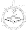
- FIG. 7 depicts a rear cross-sectional view of an exemplary tissue sample holder with a flow restriction device.
- FIG. 8 depicts a rear, perspective cross-sectional view of the tissue sample holder of FIG. 7 , with the flow restriction device removed.
- FIG. 9 depicts an exemplary flow restriction device.
- FIG. 10 depicts a partial rear perspective view of an alternate biopsy device and an alternate tissue sample holder, attached to an exemplary fluid retention device.
- FIG. 11 depicts an alternate tissue sample holder having an enlarged fluid collection chamber, attached to the biopsy device of FIG. 1 .
- an exemplary biopsy device ( 10 ) comprises a needle ( 20 ), a body ( 30 ), and a tissue sample holder ( 40 ).
- needle ( 20 ) extends distally from the distal portion of body ( 30 ), while tissue sample holder ( 40 ) extends proximally from the proximal portion of body ( 30 ).
- Body ( 30 ) is sized and configured such that biopsy device ( 10 ) may be operated by a single hand of a user.
- a user may grasp body ( 30 ) with a single hand, insert needle ( 20 ) into a patient's breast, and collect one or a plurality of tissue samples from within the patient's breast, all with just using a single hand.
- a user may grasp body ( 30 ) with more than one hand and/or with any desired assistance.
- the user may capture a plurality of tissue samples with just a single insertion of needle ( 20 ) in the patient's breast.
- tissue samples may be pneumatically deposited in tissue sample holder ( 40 ), as described in greater detail below, then retrieved from tissue sample holder ( 40 ) for analysis.
- Body ( 30 ) of the present example comprises a probe ( 12 ) and a holster ( 14 ).
- probe ( 12 ) is separable from holster ( 14 ).
- probe ( 12 ) and holster ( 14 ) may be removably coupled using bayonet mounts (not shown) or any other suitable structures or features.
- Use of the term “holster” herein should not be read as requiring any portion of probe ( 12 ) to be inserted into any portion of holster ( 14 ). Indeed, in some variations of biopsy device ( 10 ), probe ( 12 ) may simply sit on holster ( 14 ).
- holster ( 14 ) may be inserted into probe ( 12 ).
- probe ( 12 ) and holster ( 14 ) may be of unitary or integral construction, such that the two components cannot be separated.
- probe ( 12 ) and holster ( 14 ) are provided as separable components
- probe ( 12 ) may be provided as a disposable component
- holster ( 14 ) may be provided as a reusable component. Still other suitable structural and functional relationships between probe ( 12 ) and holster ( 14 ) will be apparent to those of ordinary skill in the art in view of the teachings herein.
- biopsy device ( 10 ) may include one or more sensors (not shown), in probe ( 12 ) and/or in holster ( 14 ), that is/are configured to detect when probe ( 12 ) is coupled with holster ( 14 ).
- sensors or other features may further be configured to permit only certain types of probes ( 12 ) and holsters ( 14 ) to be coupled together.
- sensors may be configured to disable one or more functions of probes ( 12 ) and/or holsters ( 14 ) until a suitable probe ( 12 ) and holster ( 14 ) are coupled together.
- sensors and features may be varied or omitted as desired.
- biopsy device ( 10 ) may be used in a variety of other procedures for a variety of other purposes and in a variety of other parts of a patient's anatomy.
- needle ( 20 ) of the present example comprises a cannula ( 21 ) with a tissue piercing tip ( 22 ), a lateral aperture ( 24 ), a first lumen ( 26 ), and a second lumen ( 28 ).
- Tissue piercing tip ( 22 ) is configured to pierce and penetrate tissue, without requiring a high amount of force, and without requiring an opening to be pre-formed in the tissue prior to insertion of tip ( 22 ).
- a cutter ( 50 ) is disposed in first lumen ( 26 ), and is operable to rotate and translate within first lumen ( 26 ) as will be described in greater detail below.
- Lateral aperture ( 24 ) is located proximal to tip ( 22 ), is in fluid communication with first lumen ( 26 ), and is configured to receive tissue when needle ( 20 ) is inserted in a breast and when a cutter ( 50 ) is retracted as will also be described in greater detail below.
- a plurality of openings ( 27 ) may provide fluid communication between first and second lumens ( 26 , 28 ).
- a plurality of external openings may also be formed in needle ( 20 ), and may be in fluid communication with second lumen ( 28 ). Examples of such external openings are disclosed in U.S. Pub. No. 2007/0032742, entitled “Biopsy Device with Vacuum Assisted Bleeding Control,” published Feb. 8, 2007, the disclosure of which is incorporated by reference herein. Of course, as with other components described herein, such external openings are merely optional.
- Needle ( 20 ) of the present example further comprises a hub ( 200 ), as shown in FIGS. 3-6 .
- Hub ( 200 ) may be formed of plastic that is overmolded about needle ( 20 ) or otherwise secured to needle ( 20 ), such that hub ( 200 ) is unitarily secured to needle ( 20 ).
- hub ( 200 ) may be formed of any other suitable material through any suitable process and may have any other suitable relationship with needle ( 20 ).
- Hub ( 200 ) of the present example comprises a sleeve portion ( 204 ).
- Sleeve portion ( 204 ) extends integrally into probe portion ( 12 ) of body ( 30 ).
- sleeve portion ( 204 ) defines a hollow interior ( 206 ), which is in fluid communication with second lumen ( 28 ) of needle ( 20 ).
- Sleeve portion ( 204 ) also defines a plurality of openings ( 208 ), which are radially spaced about the perimeter of sleeve portion ( 204 ) at a common longitudinal position, and which are in fluid communication with hollow interior ( 206 ). Openings ( 208 ) are exposed to ambient air, such that openings ( 208 ) provide a vent in the present example.
- Openings ( 208 ) are selectively fluidly coupled with second lumen ( 28 ) of needle ( 20 ) in this example, as will be described in greater detail below.
- openings ( 208 ) are selectively coupled with second lumen ( 28 ) during use of biopsy device ( 10 ), to selectively provide venting to second lumen ( 28 ).
- a pair of o-rings ( 210 ) are positioned about a shuttle valve slider ( 152 ), to substantially seal second lumen ( 28 ) relative to openings ( 208 ) when second lumen ( 28 ) is not to be vented, depending on the longitudinal position of slider ( 152 ) as will be described in greater detail below.
- a seal ( 212 ) is also provided at the proximal end of sleeve ( 204 ), at the interface of cutter ( 50 ) and sleeve ( 204 ).
- Seal ( 212 ) is configured to substantially seal the interface of cutter ( 50 ) and sleeve ( 204 ), even as cutter ( 50 ) rotates and translates relative to sleeve ( 204 ).
- seal ( 212 ) sealingly engages a smooth portion ( 254 ) of a sleeve ( 250 ) that is unitarily secured to cutter ( 50 ).
- Sleeve ( 250 ) further comprises a hex portion ( 252 ).
- needle ( 20 ) and hub ( 200 ) may be configured in accordance with any of the teachings in U.S. Non-Provisional patent application Ser. No. 12/483,305, entitled “Tetherless Biopsy Device with Reusable Portion,” filed Jun. 12, 2009, the disclosure of which is incorporated by reference herein.
- Still other ways in which needle ( 20 ) and/or hub ( 200 ) may be formed, including alternative techniques, materials, features, components, configurations, functionalities, and operabilities, will be apparent to those of ordinary skill in the art in view of the teachings herein.
- body ( 30 ) of the present example comprises a probe portion ( 12 ) and a holster portion ( 14 ).
- a battery (not shown), a first circuit board ( 35 ), a second circuit board (not shown), a motor ( 36 ), and a vacuum pump ( 38 ) are provided within probe portion ( 12 ).
- the battery may comprise a rechargeable battery, a non-rechargeable battery, or any other type of battery.
- biopsy device ( 10 ) is powered by some other source, such as a conventional alternating current (AC) power source or piece of capital equipment, such that the battery is merely optional.
- AC alternating current
- the battery is coupled with motor ( 36 ) via first circuit board ( 35 ), second circuit board (not shown) and a trigger button (not shown) in the present example.
- the battery may be similar to the battery disclosed in U.S. Non-Provisional patent application Ser. No. 12/483,305, entitled “Tetherless Biopsy Device with Reusable Portion,” filed Jun. 12, 2009, the disclosure of which is incorporated by reference herein.
- motor ( 36 ) of the present example is in mechanical communication with vacuum pump ( 38 ) and a cutter actuation mechanism ( 60 ).
- motor ( 36 ) is operable to simultaneously activate vacuum pump ( 38 ) and cutter actuation mechanism ( 60 ) when motor ( 36 ) is activated.
- vacuum pump ( 38 ) and cutter actuation mechanism ( 60 ) may be activated in any other suitable fashion.
- vacuum pump ( 38 ) and/or cutter actuation mechanism ( 60 ) may be activated manually and/or by separate motors and/or in any other suitable fashion.
- Motor ( 36 ) of the present example comprises a conventional DC motor.
- motor ( 36 ) may alternatively comprise a pneumatic motor (e.g., with impeller, etc.), a pneumatic linear actuator, an electromechanical linear actuator, or a variety of other types of movement-inducing devices.
- a pneumatic motor e.g., with impeller, etc.
- a pneumatic linear actuator e.g., with impeller, etc.
- an electromechanical linear actuator e.g., a pneumatic linear actuator
- electromechanical linear actuator e.g., etc.
- Other types of movement-inducing devices may be incorporated into biopsy device ( 10 ) will be apparent to those of ordinary skill in the art in view of the teachings herein.
- a drive shaft ( 62 ) extends from motor ( 36 ), and is rotationally driven by motor ( 36 ).
- a pair of bearings ( 70 ) and a drive gear ( 72 ) are positioned about drive shaft ( 62 ). Bearings ( 70 ) support drive shaft ( 62 ), while drive gear ( 72 ) rotates unitarily with drive shaft ( 62 ).
- motor ( 36 ) may be selectively activated to rotate drive shaft ( 62 ) and drive gear ( 72 ) in either rotational direction.
- Drive gear ( 72 ) meshes with a second gear ( 74 ), which is unitarily secured to a second shaft ( 64 ).
- Second shaft ( 64 ) also includes associated bearings ( 70 ) and a third gear ( 76 ). Second shaft ( 64 ) and gears ( 74 , 76 ) rotate unitarily, such that motor ( 36 ) is operable to rotatingly drive second shaft ( 64 ) and gears ( 74 , 76 ) via drive shaft ( 62 ) and drive gear ( 72 ).
- Vacuum pump ( 38 ) of the present example comprises a conventional diaphragm pump.
- the second shaft ( 64 ) which is rotationally driven by motor ( 36 ) as described above, is coupled with an eccentric disk (not shown—e.g., a device for converting circular motion into rectilinear motion, comprising a disk fixed off-center to second shaft ( 64 )), which is configured to cause a rod (not shown—e.g., the rod may be coupled with or otherwise driven by the eccentric disk) of vacuum pump ( 38 ) to reciprocate as motor ( 36 ) and shafts ( 62 , 64 ) rotate.
- an eccentric disk not shown—e.g., a device for converting circular motion into rectilinear motion, comprising a disk fixed off-center to second shaft ( 64 )
- a rod not shown—e.g., the rod may be coupled with or otherwise driven by the eccentric disk) of vacuum pump ( 38 ) to reciprocate as motor ( 36 ) and shafts ( 62 , 64 )
- This rod of vacuum pump ( 38 ) drives a diaphragm (not shown) of vacuum pump ( 38 ) as the rod reciprocates, causing vacuum pump ( 38 ) to induce a vacuum.
- vacuum pump ( 38 ) of the present example operates in the same way regardless of which direction motor ( 36 ) rotates. Of course, any other suitable type of vacuum pump may be used.
- Vacuum pump ( 38 ) of the present example is operable to induce a vacuum in tissue sample holder ( 40 ) when vacuum pump ( 38 ) is activated, as will be described in greater detail below.
- Cutter actuation mechanism ( 60 ) is operable to rotate and translate cutter ( 50 ) when cutter actuation mechanism ( 60 ) is activated, as will also be described in greater detail below.
- cutter actuation mechanism ( 60 ) is operable to cause cutter ( 50 ) to rotate within first lumen ( 26 ) and concomitantly cause cutter ( 50 ) to translate within first lumen ( 26 ), such as to sever a biopsy sample from tissue protruding through lateral aperture ( 24 ).
- body ( 30 ) and its associated components may be configured in accordance with any of the teachings in U.S. Non-Provisional patent application Ser. No. 12/483,305, entitled “Tetherless Biopsy Device with Reusable Portion,” filed Jun. 12, 2009, the disclosure of which is incorporated by reference herein.
- Still other ways in which body ( 30 ) and/or its associated components may be formed, including alternative techniques, materials, features, components, configurations, functionalities, and operabilities, will be apparent to those of ordinary skill in the art in view of the teachings herein.
- biopsy device ( 10 ) also includes a valve mechanism ( 150 ) in the present example
- Valve mechanism ( 150 ) may be similar to the valve mechanism disclosed in U.S. Non-Provisional patent application Ser. No. 12/483,305, entitled “Tetherless Biopsy Device with Reusable Portion,” filed Jun. 12, 2009, the disclosure of which is incorporated by reference herein.
- Valve mechanism ( 150 ) of this example comprises shuttle valve slider ( 152 ), o-rings ( 210 ), and sleeve ( 204 ) of needle hub ( 200 ).
- Shuttle valve slider ( 152 ) is positioned coaxially about cutter ( 50 ), and is configured to translate relative to sleeve ( 204 ) and relative to cutter ( 50 ).
- Shuttle valve slider ( 152 ) defines an inner diameter that is greater than the outer diameter defined by cutter ( 50 ), such that a gap is provided between the outer diameter of cutter ( 50 ) and the inner diameter of shuttle valve slider ( 152 ). Such a gap is sufficient to provide longitudinal fluid communication (e.g., atmospheric air, etc.) between the outer diameter of cutter ( 50 ) and the inner diameter of shuttle valve slider ( 152 ).
- the proximal end of shuttle valve slider ( 152 ) has notches ( 153 ) formed in it, providing an appearance similar to that of a castellated nut or castle nut.
- stop member ( 55 ) and shuttle valve slider ( 152 ) are configured such that stop member ( 55 ) may push shuttle valve slider ( 152 ) proximally when stop member ( 55 ) is engaged with shuttle valve slider ( 152 ); while sleeve ( 250 ) and shuttle valve slider ( 152 ) are configured such that sleeve ( 250 ) may push shuttle valve slider ( 152 ) distally when sleeve ( 250 ) is engaged with shuttle valve slider ( 152 ).
- shuttle valve slider ( 152 ) and the other components of valve mechanism ( 150 ) may be configured to allow shuttle valve slider ( 152 ) to selectively substantially seal second lumen ( 28 ) relative to openings ( 208 ) when cutter ( 50 ) is in a proximal position and to selectively vent second lumen ( 28 ) to atmosphere when cutter ( 50 ) is at other positions.
- valve mechanism ( 150 ) may be varied, modified, substituted, or supplemented in a variety of ways; and that valve mechanism ( 150 ) may have a variety of alternative features, components, configurations, and functionalities. Suitable alternative versions, features, components, configurations, and functionalities of valve mechanism ( 150 ) will be apparent to those of ordinary skill in the art in view of the teachings herein.
- valve mechanism ( 150 ) and/or any of its components may be configured in accordance with any of the teachings in U.S. Non-Provisional patent application Ser. No. 12/483,305, entitled “Tetherless Biopsy Device with Reusable Portion,” filed Jun. 12, 2009, the disclosure of which is incorporated by reference herein.
- tissue sample holder ( 40 ) of the present example comprises a cap ( 42 ), an outer cup ( 44 ), and a collection tray ( 46 ).
- Tissue sample holder ( 40 ) provides a fluid management system that is configured to facilitate separation of tissue samples from associated fluids as will be described in greater detail below.
- Cup ( 44 ) is secured to probe ( 12 ) in the present example. Such engagement may be provided in any suitable fashion (e.g., snap fitting, complementary rigid locking features, etc.).
- Outer cup ( 44 ) of the present example is substantially transparent, allowing the user to view tissue samples on collection tray ( 46 ), though outer cup ( 44 ) may have any other suitable properties if desired.
- Collection tray ( 46 ) divides the interior space defined by outer cup ( 44 ) into an upper chamber ( 43 a ) and a lower chamber ( 43 b ).
- the fluid management system provided by tissue sample holder ( 40 ) is configured to retain tissue samples in upper chamber ( 43 a ) while permitting associated fluids to flow into lower chamber ( 43 b ).
- Outer cup ( 44 ) is in fluid communication with cutter lumen ( 52 ) and with vacuum pump ( 38 ) in the present example.
- outer cup ( 44 ) is in fluid communication with cutter lumen ( 52 ) via a first port ( 45 ); and is in fluid communication with vacuum pump ( 38 ) via a second port ( 47 ).
- a conduit ( 39 ) couples port ( 41 ) of vacuum pump ( 38 ) with second port ( 47 ) of outer cup ( 44 ).
- a spring-loaded seal may optionally be provided on conduit ( 39 ) and/or second port ( 47 ) and/or port ( 41 ) of vacuum pump ( 38 ), to substantially seal tissue sample holder ( 40 ) and/or vacuum pump ( 38 ) when conduit ( 39 ) is disconnected from tissue sample holder ( 40 ) or vacuum pump ( 38 ) and/or when probe ( 12 ) is decoupled from holster ( 14 ).
- second port ( 47 ) is further coupled with a hydrophobic filter ( 48 ), which is in fluid communication with the interior space defined by outer cup ( 44 ).
- Hydrophobic filter ( 48 ) is configured to permit vacuum pump ( 38 ) to induce a vacuum in tissue sample holder ( 40 ) while preventing liquids from being communicated from tissue sample holder ( 40 ) to vacuum pump ( 38 ).
- a highly absorbent material may be provided in tissue sample holder ( 40 ) to soak up liquids.
- liquids may be dealt with in any other suitable fashion.
- the vacuum created in tissue sample holder ( 40 ) by vacuum pump ( 38 ) is communicated to cutter ( 50 ) in the present example.
- vacuum pump ( 38 ) may thus be used to induce a vacuum in cutter lumen ( 52 ); with such a vacuum being communicated through conduit ( 39 ), ports ( 41 , 45 , 47 ), and the interior of outer cup ( 44 ).
- Collection tray ( 46 ) may comprise plastic or any other suitable material or combination of materials.
- collection tray ( 46 ) is formed as an integral feature of outer cup ( 44 ).
- collection tray ( 46 ) is formed separately from outer cup ( 44 ), such that the two are later joined together.
- collection tray ( 46 ) may be removable from outer cup ( 44 ) or may remain permanently fixed relative to outer cup ( 44 ) after collection tray ( 46 ) is joined with outer cup ( 44 ).
- Collection tray ( 46 ) of the present example has a tapered configuration, and has a filter opening ( 147 ) formed therethrough.
- the tapered configuration of collection tray ( 46 ) provides ramps leading downwardly toward filter opening ( 147 ), such that gravity and the configuration of collection tray ( 46 ) leads liquids toward filter opening ( 147 ).
- these ramp features are substantially straight.
- collection tray ( 46 ) has a rounded bowl shape, with filter opening ( 147 ) being positioned at the bottom center of the bowl shape. Still other suitable configurations for collection tray ( 46 ) will be apparent to those of ordinary skill in the art in view of the teachings herein.
- a flow restriction device ( 49 ) is positioned within filter opening ( 147 ).
- Flow restriction device ( 49 ) may be configured to selectively control the flow of fluids between upper chamber ( 43 a ) and lower chamber ( 43 b ). Accordingly, fluids may be collected in lower chamber ( 43 b ) and separated from tissue samples retained in upper chamber ( 43 a ).
- Filter opening ( 147 ), without flow restriction device ( 49 ), may be sized and configured to permit the passage of fluids therethrough while preventing the passage of tissue samples therethrough.
- filter opening ( 147 ) may be sized to permit the passage of tissue samples therethrough, however flow restriction device ( 49 ) may be configured to prevent the passage of tissue samples through filter opening ( 147 ) when flow restriction device ( 49 ) is positioned within filter opening ( 147 ).
- collection tray ( 46 ) is positioned below first port ( 45 ) which is in fluid communication with cutter lumen ( 52 ). Collection tray ( 46 ) is thus configured to receive tissue samples and associated fluids that are communicated proximally through cutter ( 50 ) as will be described in greater detail below. Collection tray ( 46 ) may be sized and shaped to receive a plurality of tissue samples for instances when the user collects multiple samples during a single procedure. In the illustrated version, the surfaces of collection tray ( 46 ) are tapered or sloped downward toward filter opening ( 147 ) to direct fluids toward filter opening ( 147 ) via gravity. It should be understood that collection tray ( 46 ) may take a variety of alternate forms.
- collection tray ( 46 ) may comprise a funnel-shape or a convex shape to direct fluids toward filter opening ( 147 ).
- collection tray ( 46 ) may comprise a plurality of filter openings and corresponding flow restriction devices. While filter opening ( 147 ) of the present example is a circular opening positioned substantially in the center of collection tray ( 46 ), it will be appreciated that filter opening may comprise any shape and location suitable to allow fluids to pass from upper chamber ( 43 a ) into lower chamber ( 43 b ).
- FIG. 9 depicts an exemplary flow restriction device ( 49 ).
- Flow restriction device ( 49 ) of the present example operates like a check valve, such that it selectively prevents flow of fluids through filter opening ( 147 ).
- flow restriction device ( 49 ) allows fluids to flow from upper chamber ( 43 a ) into lower chamber ( 43 b ) while preventing the flow of fluids from lower chamber ( 43 b ) into upper chamber ( 43 a ).
- flow restriction device ( 49 ) may be selectively transitioned between an “open configuration” (e.g., such that fluids are permitted to flow from upper chamber ( 43 a ) into lower chamber ( 43 b ) when upper chamber ( 43 a ) is at atmospheric pressure) and a “closed configuration” (e.g., such that fluids are prevented from flowing from lower chamber ( 43 b ) into upper chamber ( 43 a ) when a vacuum is applied to upper chamber ( 43 a )).
- an “open configuration” e.g., such that fluids are permitted to flow from upper chamber ( 43 a ) into lower chamber ( 43 b ) when upper chamber ( 43 a ) is at atmospheric pressure
- a “closed configuration” e.g., such that fluids are prevented from flowing from lower chamber ( 43 b ) into upper chamber ( 43 a ) when a vacuum is applied to upper chamber ( 43 a )
- flow restriction device may be “vacuum activated” such that flow restriction device ( 49 ) transitions from an open position to a closed position when a vacuum is introduced in outer cup ( 44 )/upper chamber ( 43 a ).
- fluids are permitted to flow from upper chamber ( 43 a ) into lower chamber ( 43 b ) when outer cup ( 44 )/upper chamber ( 43 a ) is at atmospheric pressure, while flow restriction device ( 49 ) closes or seals filter opening ( 147 ) when a vacuum is induced in outer cup ( 44 )/upper chamber ( 43 a ) such that fluids are prevented from flowing from lower chamber ( 43 b ) into upper chamber ( 43 a ).
- flow restriction device ( 49 ) may be formed of a resilient material that deforms under the influence of a vacuum to transition between open and closed configurations.
- flow restriction device ( 49 ) may include a resilient member (e.g., spring, etc.) that bears against collection tray ( 46 ) to resiliently bias flow restriction device ( 49 ).
- flow restriction device ( 49 ) may be resiliently biased to either the open configuration or the closed configuration, with flow restriction device ( 49 ) transitioning to the other configuration based on whether upper chamber ( 43 a ) is under a vacuum or atmospheric pressure.
- flow restriction device ( 49 ) “floats” when outer cup ( 44 )/upper chamber ( 43 a ) is at atmospheric pressure, such that filter opening ( 147 ) remains substantially open, allowing fluids to flow from upper chamber ( 43 a ) into lower chamber ( 43 b ) and vice-versa. Also in the present example, flow restriction device ( 49 ) is drawn toward upper chamber ( 43 a ) when a vacuum is induced in outer cup ( 44 )/upper chamber ( 43 a ), thereby closing or sealing filter opening ( 147 ) and preventing fluids from flowing from lower chamber ( 43 b ) into upper chamber ( 43 a ) and vice-versa.
- Flow restriction device ( 49 ) may comprise a floating valve seat (as shown in FIG.
- flow restriction device ( 49 ) may comprise vacuum fitting part no. HS 18-SV-SS, a valve cup assembly comprising vacuum fitting part no. HS 18-SV-SS and valve cup F77-NBR, a valve cup assembly comprising vacuum fitting part no. HS 18-SV-SS and valve cup F77-SIT, or a 75 Button Valve (part no.
- flow restriction device ( 49 ) may comprise a duckbill check valve (part no. CKV-M3) available from Beswick Engineering Corp., Inc. of Greenland, N.H., or a Type 369 Wafer Check Valve available from GF Piping Systems of Tustin, Calif.
- CKV-M3 duckbill check valve
- Other suitable forms that flow restriction device ( 49 ) may take will be apparent to those of ordinary skill in the art in view of the teachings herein.
- Cap ( 42 ) is removably coupled with outer cup ( 44 ) in the present example.
- a pair of latches ( 56 ) provide selective engagement between cap ( 42 ) and outer cup ( 44 ).
- latches ( 56 ) engage a lip ( 57 ) of outer cup ( 44 ).
- Lip ( 57 ) has gaps ( 59 ) permitting passage of latches ( 56 ), such that a user may secure cap ( 42 ) to outer cup ( 44 ) by aligning latches ( 56 ) with gaps ( 59 ), pushing cap ( 42 ) onto outer cup ( 44 ), then rotating cap ( 42 ) past gaps ( 59 ) to engage latches ( 56 ) with lip ( 57 ).
- cap ( 42 ) may be secured to outer cup ( 44 ) in any other suitable fashion.
- An o-ring ( 53 ) provides a seal when cap ( 42 ) is engaged with outer cup ( 44 ).
- a vacuum may thus be maintained within outer cup ( 44 ) when cap ( 42 ) is secured to outer cup ( 44 ).
- a user may remove cap ( 42 ) to access tissue samples that have gathered on collection tray ( 46 ) during a biopsy process.
- cap ( 42 ) is removed by rotating cap ( 42 ) to align latches ( 56 ) with gaps ( 59 ), then pulling cap ( 42 ) off.
- cap ( 42 ) may be removed from outer cup ( 44 ) in any other suitable fashion.
- Tissue sample holder ( 40 ) of the present example is configured to hold at least ten tissue samples.
- tissue sample holder ( 40 ) may be configured to hold any other suitable number of tissue samples.
- tissue sample holder ( 40 ) may be varied, modified, substituted, or supplemented in a variety of ways; and that tissue sample holder ( 40 ) may have a variety of alternative features, components, configurations, and functionalities.
- tissue sample holder ( 40 ) may be alternatively configured such that it has a plurality of discrete tissue sample compartments that may be selectively indexed to cutter lumen ( 52 ). Such indexing may be provided automatically or manually.
- tissue sample holder ( 40 ) may be configured and operable in accordance with the teachings of U.S. Pub. No. 2008/0195066, entitled “Revolving Tissue Sample Holder for Biopsy Device,” published Aug. 14, 2008, the disclosure of which is incorporated by reference herein; U.S. Non-Provisional patent application Ser. No. 12/337,997, entitled “Tissue Biopsy Device with Rotatably Linked Thumbwheel and Tissue Sample Holder,” filed Dec. 18, 2008; U.S. Non-Provisional patent application Ser. No. 12/337,911, entitled “Biopsy Device with Discrete Tissue Chambers,” filed Dec. 18, 2008, the disclosure of which is incorporated by reference herein; or U.S. Non-Provisional patent application Ser.
- tissue sample holder ( 40 ) may simply be omitted, if desired.
- FIG. 10 depicts an exemplary alternate embodiment in which tissue sample holder ( 40 ) is in fluid communication with a fluid container ( 140 ) that is located external to biopsy device ( 10 ).
- lower chamber ( 43 b ) includes a drainage opening ( 142 ) in outer cup ( 44 ) in this example. Drainage opening ( 142 ) is configured to allow fluids collected in lower chamber ( 43 b ) to flow out of lower chamber ( 43 b ) and into fluid container ( 140 ) via tubing ( 144 ).
- Tubing ( 144 ) may comprise plastic tubing or any other structure or device suitable to transfer liquids from lower chamber ( 43 b ) to fluid container ( 140 ).
- Drainage opening ( 142 ) may be suitably shaped, sized, and positioned to efficiently drain fluids from lower chamber ( 43 b ).
- Fluid container ( 140 ) may comprise a fluid collection bag, canister, or any other structure or device suitable to receive and collect fluids.
- fluid container ( 140 ) may be any suitable size and shape. The ability to deposit fluids into fluid container ( 140 ) may provide additional flexibility for the user in acquiring multiple samples and managing bleeding because the fluid container ( 140 ) may hold more fluids than lower chamber ( 43 b ) could otherwise hold by itself.
- fluid container ( 140 ) may provide additional flexibility when biopsy device ( 10 ) is used in stereotactic or x-ray procedures by reducing the need to directly access tissue sample holder ( 40 ) during the procedure to deal with fluids collected during the procedure.
- Other suitable alternative versions, features, components, configurations, and functionalities of fluid container ( 140 ) will be apparent to those of ordinary skill in the art in view of the teachings herein.
- FIG. 11 depicts another exemplary alternate tissue sample holder ( 340 ) engaged with a biopsy device ( 310 ).
- the components of biopsy device ( 310 ) may be substantially similar to the components of biopsy device ( 10 ) described herein, aside from tissue sample holder ( 340 ) replacing tissue sample holder ( 40 ).
- tissue sample holder ( 340 ) comprises an upper portion ( 350 ) and a lower portion ( 360 ).
- Upper portion ( 350 ) may be releasably or fixedly engaged with lower portion ( 360 ).
- upper portion ( 350 ) may be integral with lower portion ( 360 ).
- Upper portion ( 350 ) may be substantially similar to the upper portion of outer cup ( 44 ) described herein.
- upper portion ( 350 ) comprises an upper chamber ( 352 ) that is in fluid communication with first port ( 45 ) and second port ( 47 ) of biopsy device ( 310 ).
- Upper chamber ( 352 ) further comprises a collection tray ( 354 ) that is substantially similar to collection tray ( 46 ) described herein.
- Collection tray ( 354 ) is configured to receive tissue samples and associated fluids that are communicated proximally through cutter ( 50 ).
- Collection tray ( 354 ) comprises a filter opening ( 356 ) similar to filter opening ( 147 ) described herein.
- Collection tray ( 354 ) further comprises a flow restriction device (not shown) similar to flow restriction device ( 49 ) described herein.
- Upper chamber ( 352 ) is in selective fluid communication with a fluid collection chamber (not shown) in lower portion ( 360 ) via filter opening ( 356 ) and the flow restriction device (not shown).
- the fluid collection chamber in lower portion ( 360 ) may be configured to receive and collect fluids from upper chamber ( 352 ), just like lower chamber ( 43 b ) described above. However, the fluid collection chamber in lower portion ( 360 ) in this example may be larger and able to retain a larger amount of fluids compared to lower chamber ( 43 b ) described above.
- the fluid collection chamber in lower portion ( 360 ) may have a semi-circular cross-section with a radius that is larger than the radius of upper chamber ( 352 ).
- lower portion ( 360 ) may be disengaged from upper portion to allow a user to dispose of fluids stored therein and re-attach lower portion ( 360 ) or to replace a first, full lower portion ( 360 ) with a second, empty lower portion ( 360 ), although this functionality is not required.
- lower portion ( 360 ) having a larger fluid collection chamber may provide additional flexibility for the user in acquiring multiple samples and managing bleeding because the fluid collection chamber may hold more fluids than lower chamber ( 43 b ). Additionally, the use of lower portion ( 360 ) having a larger fluid collection chamber may provide additional flexibility when biopsy device ( 10 ) is used in stereotactic or x-ray procedures by reducing the need to directly access tissue sample holder ( 340 ) during the procedure to deal with fluids collected during the procedure.
- Other suitable alternative versions, features, components, configurations, and functionalities of lower portion ( 360 ) will be apparent to those of ordinary skill in the art in view of the teachings herein.
- a removable cap (not shown) is provided for upper portion ( 350 ), with such a cap being similar to cap ( 42 ) described above.
- a cap may take a variety of forms.
- such a cap may comprise a semi-circular door that hingedly folds up and down to selectively close or open the proximal side of upper portion ( 350 ).
- Such a door may include a seal on the inside panel of the door and a latch at the top to selectively keep the door substantially closed.
- a cap for upper portion ( 350 ) may comprise a separate semi-circular piece that selectively clips, latches, or otherwise removably secures to the proximal side of upper portion ( 350 ).
- such a cap may comprise a door that slides up and down vertically, like a tray separator sliding in and out of an organizing tray, to selectively open and close the proximal side of upper portion ( 350 ).
- a cap of upper portion ( 350 ) may take will be apparent to those of ordinary skill in the art in view of the teachings herein.
- lower portion ( 360 ) is configured such that its proximal side is not open, such that lower portion ( 360 ) does not need or otherwise include a removable cap.
- lower portion ( 360 ) may have its own removable cap.
- Such a removable cap may be similar to or different from a removable cap for upper portion ( 350 ).
- a single cap (not shown) is used to selectively cover/close or uncover/open the proximal side of both upper portion ( 350 ) and lower portion ( 360 ).
- a cap may be substantially similar to cap ( 42 ) described above, with such a cap having a shape the complements the differing sizes and shapes of upper portion ( 350 ) and lower portion ( 360 ).
- upper portion ( 350 ) and lower portion ( 360 ) may be selectively covered/closed and/or uncovered/opened will be apparent to those of ordinary skill in the art in view of the teachings herein.
- tissue sample holder ( 40 , 340 ) may further comprise a screen or other type of filter above collection tray ( 46 , 354 ) but below first port ( 45 ).
- a screen/filter may be configured to receive tissue samples that are communicated proximally through cutter lumen ( 52 ) and first port ( 45 ), and keep such tissue samples from reaching filter opening ( 147 , 356 ) and flow restriction device ( 49 ).
- such a screen/filter may substantially prevent tissue samples from getting stuck between flow restriction device ( 49 ) and collection tray ( 46 , 354 ), which might otherwise adversely affect the effectiveness of restriction device ( 49 ).
- Such a screen/filter may nevertheless freely permit the passage of fluids therethrough, such that fluids communicated through cutter lumen ( 52 ) and first port ( 45 ) may still reach filter opening ( 147 , 356 ) and flow restriction device ( 49 ).
- a screen/filter may comprise a conventional screen, a piece of plastic or other material with openings or slots formed therethrough, or any other suitable type of structure, etc.
- Such a screen/filter may also be removable from tissue sample holder ( 40 , 340 ), such that the screen/filter may be removed from tissue sample holder ( 40 , 340 ) first with tissue samples thereon; and then the tissue samples may be removed from the screen/filter after the screen/filter has been removed from tissue sample holder ( 40 , 340 ).
- tissue sample holder 40 , 340
- cutter ( 50 ) of the present example is substantially hollow, such that cutter ( 50 ) defines a cutter lumen ( 52 ).
- Cutter ( 50 ) also has a substantially sharp distal edge ( 51 ), such that cutter ( 50 ) is operable to sever a biopsy sample from tissue protruding through lateral aperture ( 24 ) of needle ( 20 ).
- the distal end of cutter ( 50 ) may have any other suitable configuration.
- a proximal portion of cutter ( 50 ) extends into tissue sample holder ( 40 ). A vacuum created in tissue sample holder ( 40 ) by vacuum pump ( 38 ) is thus communicated to cutter lumen ( 52 ).
- a seal ( 54 ) is provided at the interface of cutter ( 50 ) and outer cup ( 44 ).
- Seal ( 54 ) is configured to substantially seal the interface of cutter ( 50 ) and outer cup ( 44 ), even as cutter ( 50 ) rotates and translates relative to outer cup ( 44 ).
- cutter ( 50 ) is configured such that it remains in sealed fluid communication with the interior of tissue sample holder ( 40 ) even when cutter ( 50 ) is in a distal most position.
- the length of cutter ( 50 ) may be such that at least a portion of cutter ( 50 ) is always disposed in outer cup ( 44 ) of tissue sample holder ( 40 ) during operation of biopsy device ( 10 ).
- cutter ( 50 ) may have any other suitable alternative features or configurations.
- cutter ( 50 ) may have any other suitable alternative relationships with tissue sample holder ( 40 ).
- cutter ( 50 ) may be varied, modified, substituted, or supplemented in a variety of ways; and that cutter ( 50 ) may have a variety of alternative features, components, configurations, and functionalities. Suitable alternative versions, features, components, configurations, and functionalities of cutter ( 50 ) will be apparent to those of ordinary skill in the art in view of the teachings herein.
- cutter ( 50 ) and/or one of its components may be configured in accordance with any of the teachings in U.S. Non-Provisional patent application Ser. No. 12/483,305, entitled “Tetherless Biopsy Device with Reusable Portion,” filed Jun. 12, 2009, the disclosure of which is incorporated by reference herein.
- cutter actuation mechanism ( 60 ) and its components are configured in accordance with the teachings of the cutter actuation mechanism and components disclosed in U.S. Non-Provisional patent application Ser. No. 12/483,305, entitled “Tetherless Biopsy Device with Reusable Portion,” filed Jun. 12, 2009, the disclosure of which is incorporated by reference herein.
- FIGS. 12/483,305 entitled “Tetherless Biopsy Device with Reusable Portion,” filed Jun. 12, 2009, the disclosure of which is incorporated by reference herein.
- cutter actuation mechanism ( 60 ) of the present example comprises motor ( 36 ), shafts ( 62 , 64 , 68 , 69 ), gears ( 72 , 74 , 76 , 78 , 80 , 82 , 84 ), and bearings ( 70 ), each of which are contained within holster ( 14 ) in the present example.
- gear ( 72 ) is rotated by motor ( 36 ) which meshes with gear ( 74 ) to rotate gear ( 76 ) via shaft ( 64 ).
- Gear ( 76 ) meshes with gear ( 78 ) which rotates gear ( 80 ) via shaft ( 68 ).
- Gear ( 80 ) meshes with gear ( 82 ) which meshes with gear ( 86 ) and rotates gear ( 84 ) via shaft ( 69 ).
- Gear ( 84 ) meshes with gear ( 88 ).
- activation of motor ( 36 ) will rotate gears ( 82 , 84 ).
- gears ( 82 , 84 ) are partially exposed by an opening formed in a cover plate ( 18 ) of holster ( 14 ) in the present example.
- Cutter actuation mechanism ( 60 ) of the present example further comprises a hex nut ( 100 ) and a worm nut ( 120 ).
- Worm nut ( 120 ) is supported by a bushing ( 138 ).
- Hex nut ( 100 ) includes a gear ( 86 ), which is configured to rotate unitarily with hex nut ( 100 ).
- Worm nut ( 120 ) also includes a gear ( 88 ), which is configured to rotate unitarily with worm nut ( 120 ).
- Gear ( 86 ) is configured to mesh with gear ( 82 ) when probe ( 12 ) and holster ( 14 ) are coupled together; while gear ( 88 ) is configured to mesh with gear ( 84 ) when probe ( 12 ) and holster ( 14 ) are coupled together.
- gears ( 86 , 88 ) are partially exposed by an opening formed in a cover plate ( 16 ) of probe ( 12 ) in the present example.
- Motor ( 36 ) is thus operable to rotatingly drive gears ( 86 , 88 ) in the present example when probe ( 12 ) and holster ( 14 ) are coupled together. Such rotation of gears ( 86 , 88 ) will cause cutter ( 50 ) to rotate and translate simultaneously in the present example.
- Gear ( 86 ) of hex nut ( 100 ) is configured to mesh with gear ( 82 ), such that rotation of gear ( 82 ) causes rotation of hex nut ( 100 ). Such rotation of hex nut ( 100 ) will cause corresponding rotation of cutter ( 50 ).
- cutter actuation mechanism ( 60 ) may cause rotation of cutter ( 50 ) in response to activation of motor ( 36 ), with rotation of motor ( 36 ) being communicated to cutter ( 50 ) through shafts ( 62 , 64 , 68 , 69 ), gears ( 72 , 74 , 76 , 78 , 80 , 82 , 84 , 86 ), hex nut ( 100 ), and sleeve ( 250 ).
- any other suitable structures, components, configurations, or techniques may be used to provide rotation of cutter ( 50 ).
- Gears ( 82 , 84 ) of holster ( 14 ) rotate simultaneously when motor ( 36 ) is activated.
- gears ( 82 , 84 ) mesh with gears ( 86 , 88 ) of probe ( 12 ) when probe ( 12 ) is coupled with holster ( 14 ), such that activated motor ( 36 ) rotates gears ( 86 , 88 ) simultaneously.
- Activated motor ( 36 ) will thus rotate hex nut ( 100 ) and worm nut ( 120 ) simultaneously. It should therefore be understood that sleeve ( 250 ), cutter ( 50 ), lead screw ( 122 ), and worm nut ( 120 ) will all rotate simultaneously when motor ( 36 ) is activated.
- cutter ( 50 ) is retracted proximally when motor ( 36 ) is activated to rotate cutter ( 50 ) counterclockwise (viewed from tissue sample holder ( 40 ) toward needle ( 20 )); while cutter ( 50 ) is advanced distally when motor ( 36 ) is activated to rotate cutter ( 50 ) clockwise (viewed from tissue sample holder ( 40 ) toward needle ( 20 )).
- the direction of motor ( 36 ) rotation may thus be reversed to transition between distal and proximal translation of cutter ( 50 ).
- cutter actuation mechanism ( 60 ) may be configured to be self-reversing, such that cutter ( 50 ) may be translated distally and proximally without reversing the direction of motor ( 36 ) rotation.
- cutter ( 50 ) may be initially located in a distal-most position, such that lateral aperture ( 24 ) is “closed”; with lead screw ( 122 ) being positioned at the distal smooth section ( 137 ) of worm nut ( 120 ).
- Spring ( 130 ) biases lead screw ( 122 ) proximally to engage threads ( 132 ) with threads ( 134 ).
- cutter actuation mechanism ( 60 ) causes cutter ( 50 ) to retract proximally.
- proximal or rearward translation may be effected through engagement of threads ( 132 , 134 ), and due to lead screw ( 122 ) rotating at a faster speed than worm nut ( 120 ).
- Lead screw ( 122 ) continues to traverse threads ( 134 ) of worm nut ( 120 ) as cutter ( 50 ) continues to retract proximally.
- Cutter ( 50 ) then reaches a proximal-most position, such that lateral aperture ( 24 ) is “opened”.
- lead screw ( 122 ) is positioned at the proximal smooth section ( 136 ) of worm nut ( 120 ).
- Spring ( 128 ) biases lead screw ( 122 ) distally to engage threads ( 132 ) with threads ( 134 ).
- cutter ( 50 ) may again be activated, with its rotation direction being reversed to reverse the rotation direction of cutter ( 50 ) and associated components.
- motor ( 36 ) may again be activated, with its rotation direction being reversed to reverse the rotation direction of cutter ( 50 ) and associated components.
- reversing the rotational direction of motor ( 36 ) causes cutter ( 50 ) to rotate clockwise (viewed from tissue sample holder ( 40 ) toward needle ( 20 )).
- Such clockwise rotation of cutter ( 50 ) causes cutter to advance distally to reach the distal-most position again.
- cutter ( 50 ) is shown and described above as rotating counterclockwise (viewed from tissue sample holder ( 40 ) toward needle ( 20 )) during retraction of cutter ( 50 ) and clockwise (viewed from tissue sample holder ( 40 ) toward needle ( 20 )) during advancement of cutter ( 50 ), it should be immediately apparent to those of ordinary skill in the art that cutter ( 50 ) may instead be rotated clockwise during retraction of cutter ( 50 ) and counterclockwise during advancement of cutter.
- reversal may be provided by reversing the orientation of threads ( 132 , 134 ).
- such reversal may be provided by changing the differential such that worm nut ( 120 ) rotates faster than cutter ( 50 ).
- cutter actuation mechanism ( 60 ) may be varied, modified, substituted, or supplemented in a variety of ways; and that cutter actuation mechanism ( 60 ) may have a variety of alternative features, components, configurations, and functionalities.
- biopsy device ( 10 ) may be configured such that cutter ( 50 ) does not translate (e.g., such that cutter ( 50 ) merely rotates, etc.); or such that cutter ( 50 ) does not rotate (e.g., such that cutter ( 50 ) merely translates, etc.).
- Other suitable alternative versions, features, components, configurations, and functionalities of cutter actuation mechanism ( 60 ) will be apparent to those of ordinary skill in the art in view of the teachings herein.
- vacuum pump ( 38 ) is operable to induce a vacuum in tissue sample holder ( 40 ), and such vacuum may be further communicated to cutter lumen ( 52 ).
- vacuum pump ( 38 ) may induce a vacuum in upper chamber ( 43 a ) of tissue sample holder ( 40 ) which may cause flow restriction device ( 49 ) to close thereby preventing fluids from passing from lower chamber ( 43 b ) to upper chamber ( 43 a ).
- vacuum pump ( 38 ) may start building a vacuum in cutter lumen ( 52 ) as soon as motor ( 36 ) is activated; and such a vacuum may continue to build or be maintained as cutter ( 50 ) starts moving proximally toward the retracted position.
- second lumen ( 28 ) is vented to atmosphere.
- shuttle valve slider ( 152 ) is in a distal position, allowing atmospheric air to reach second lumen ( 28 )—via openings ( 208 ), notches ( 153 ), the gap between the inner diameter of shuttle valve slider ( 152 ) and the outer diameter of cutter ( 50 ), and the portion of sleeve interior ( 206 ) that is distal to shuttle valve slider ( 152 ).
- second lumen ( 28 ) may be fluidly coupled with vacuum pump ( 38 ), such that a vacuum is created in second lumen ( 28 ) at this stage.
- second lumen ( 28 ) may be fluidly coupled with vacuum pump ( 38 ), such that a vacuum is created in second lumen ( 28 ) at this stage.
- first lumen ( 26 ) When cutter ( 50 ) reaches the fully retracted position, such that lateral aperture ( 24 ) of needle ( 20 ) is “open”, a vacuum in cutter lumen ( 52 ) may continue to be further communicated through first lumen ( 26 ), which may continue to draw tissue into lateral aperture ( 24 ). Of course, some amount of tissue may naturally prolapse into lateral aperture ( 24 ) without the assistance of vacuum, such that vacuum may not even be needed to draw tissue into lateral aperture ( 24 ). At this stage, second lumen ( 28 ) is substantially sealed relative to atmosphere.
- stop member ( 55 ) has pushed shuttle valve slider ( 152 ) to a proximal position, such that o-rings ( 210 ) “straddle” openings ( 208 ) and seal against the interior sidewall of sleeve portion ( 204 ) to prevent atmospheric air from being communicated from openings ( 208 ) to second lumen ( 28 ) via hollow interior ( 206 ) of sleeve portion ( 204 ).
- motor ( 36 ) may continue to operate to run vacuum pump ( 38 ).
- motor ( 36 ) may run vacuum pump ( 38 ) for anywhere between approximately 0.5 seconds (inclusive) and approximately 4 seconds (inclusive), or for any other suitable duration, while cutter ( 50 ) remains in the fully retracted position. During this time, cutter ( 50 ) may “freewheel” (e.g., rotate in place without also translating). Such continued activation of vacuum pump ( 38 ) may substantially maintain/achieve a vacuum in tissue sample holder ( 40 ).
- vacuum pump ( 38 ) may continue to induce a vacuum in cutter lumen ( 52 ), and second lumen ( 28 ) may eventually be vented to atmosphere.
- the “lost motion” between cutter ( 50 ) and shuttle valve slider ( 152 ) leaves shuttle valve slider ( 152 ) in the proximal position until cutter ( 50 ) advances far enough for the distal end of sleeve ( 250 ) to engage the proximal end of shuttle valve slider ( 152 ).
- o-rings ( 210 ) of shuttle valve slider ( 152 ) continue to substantially seal second lumen ( 28 ) from openings ( 208 ).
- the distal end of sleeve ( 250 ) engages the proximal end of shuttle valve slider ( 152 )
- cutter ( 50 ) has continued to move distally to a sufficient degree
- the distal end of sleeve ( 250 ) eventually pushes shuttle valve slider ( 152 ) distally, such that the proximal-most o-ring ( 210 ) is eventually moved distal to openings ( 208 ).
- second lumen ( 28 ) is again vented to atmosphere as described above.
- cutter ( 50 ) again finally reaches the distal-most position, cutter ( 50 ) may completely sever the tissue protruding through lateral aperture ( 24 ), with second lumen ( 28 ) being vented.
- the pressure differential applied to the severed tissue sample may cause the severed tissue sample to be drawn proximally through cutter lumen ( 52 ) and into upper chamber ( 43 a ) of tissue sample holder ( 40 ).
- the severed tissue sample may thus be deposited on collection tray ( 46 ) of tissue sample holder ( 40 ); or on a screen positioned above collection tray ( 46 ) in tissue sample holder ( 40 ).
- any fluids drawn through cutter lumen ( 52 ) into upper chamber ( 43 a ) of tissue sample holder ( 40 ) may flow through filter opening ( 147 ) into lower chamber ( 43 b ).
- this flow of fluids from upper chamber ( 43 a ) to lower chamber ( 43 b ) occurs while a vacuum is being applied to upper chamber ( 43 a ) via second port ( 47 ).
- flow restriction device ( 49 ) permits fluid to flow from upper chamber ( 43 a ) to lower chamber ( 43 b ) while upper chamber ( 43 a ) is under a vacuum
- flow restriction device ( 49 ) does not permit fluid to flow from lower chamber ( 43 b ) to upper chamber ( 43 a ).
- this flow of fluids from upper chamber ( 43 a ) to lower chamber ( 43 b ) does not occur until upper chamber ( 43 a ) returns to atmospheric pressure.
- flow restriction device ( 49 ) permits fluid to flow from upper chamber ( 43 a ) to lower chamber ( 43 b ) while upper chamber ( 43 a ) is at atmospheric pressure, flow restriction device ( 49 ) does not permit fluid to flow from lower chamber ( 43 b ) to upper chamber ( 43 a ).
- shuttle valve slider ( 152 ) is actuated mechanically based on the axial position of cutter ( 50 ) in the present example, it should be understood that shuttle valve slider ( 152 ) or any other type of valve may instead be actuated electrically (e.g., via a separate motor or solenoid), pneumatically, or otherwise.
- a vacuum, saline, pressurized air, atmospheric air, and/or any other medium may be communicated to second lumen ( 28 ) at any suitable stage of operation of biopsy device ( 10 ) (e.g., applying vacuum or venting to second lumen ( 28 ) during and/or upon retraction of cutter ( 50 ) and/or during advancement of cutter ( 50 ), sealing second lumen during advancement of cutter ( 50 ), etc.).
- suitable alternative structures, components, configurations, or techniques for communicating severed tissue samples proximally through cutter lumen ( 52 ) to reach tissue sample holder ( 40 ) will be apparent to those of ordinary skill in the art in view of the teachings herein.
- a user first inserts tissue piercing tip ( 22 ) into the breast of a patient.
- cutter ( 50 ) may be advanced to the distal-most position, such that lateral aperture ( 24 ) of needle ( 20 ) is closed.
- insertion may be performed under visual guidance, stereotactic guidance, ultrasound guidance, MRI guidance, PEM guidance, BSGI guidance, palpatory guidance, some other type of guidance, or otherwise.
- motor ( 36 ) With needle ( 20 ) sufficiently inserted into the patient's breast, the user may then activate motor ( 36 ), which may in turn activate vacuum pump ( 38 ) and cutter actuation mechanism ( 100 ).
- Such activation of vacuum pump ( 38 ) may induce a vacuum in tissue sample holder ( 40 ) and cutter lumen ( 52 ) as described above.
- Such activation of cutter actuation mechanism ( 60 ) may cause cutter ( 50 ) to rotate counterclockwise and translate proximally.
- vacuum from vacuum pump ( 38 ) (as communicated through tissue sample holder ( 40 ) and cutter lumen ( 52 )) may draw tissue into lateral aperture ( 24 ) of needle ( 20 ).
- second lumen ( 28 ) may be vented by valve mechanism ( 150 ).
- vacuum may still be communicated through vacuum lumen ( 52 ) and first lumen ( 26 ), drawing tissue into lateral aperture ( 24 ) of needle ( 20 ).
- Second lumen ( 28 ) may be substantially sealed by valve assembly ( 150 ) at this time.
- lead screw ( 122 ) freewheels yet is biased distally by spring ( 128 ) as cutter ( 50 ) continues to rotate counterclockwise. Lateral aperture ( 24 ) is fully open at this stage, with tissue prolapsed therein.
- cutter ( 50 ) begins to advance distally until again reaching the distal-most position.
- vacuum is still being communicated through vacuum lumen ( 52 ), helping to hold tissue in place as sharp distal edge ( 51 ) of cutter ( 50 ) begins to sever the tissue.
- Second lumen ( 28 ) is initially substantially sealed by valve assembly ( 150 ) at this time, but is eventually vented.
- Cutter ( 50 ) then reaches the distal-most position, thereby “closing” lateral aperture ( 24 ), and such that sharp distal edge ( 51 ) of cutter ( 50 ) completely severs the tissue.
- Vacuum is still being communicated through cutter lumen ( 52 ) at this time, and valve assembly ( 150 ) vents second lumen ( 28 ).
- this combination of vacuum and venting provides communication of the severed tissue sample proximally through cutter lumen ( 52 ) and onto collection tray ( 46 ) of tissue sample holder ( 40 ).
- Motor ( 36 ) may continue to operate at the end of the cutting stroke, thereby continuing to drive vacuum pump ( 38 ) to maintain a vacuum in tissue sample holder ( 40 ).
- spring ( 130 ) biases lead screw ( 122 ) proximally to engage threads ( 132 ), while allowing cutter ( 50 ) to continue rotating at the distal-most position.
- a cutting stroke will thus be complete, and may be initiated as many times as desired to acquire additional tissue samples.
- Fluids communicated onto collection tray ( 46 ) during a cutting stroke may drain via gravity through filter opening ( 147 ) into lower chamber ( 43 b ) when upper chamber ( 43 a ) is at atmospheric pressure. Fluids captured in lower chamber ( 43 b ) may be prevented from flowing back into upper chamber ( 43 a ) by flow restriction device ( 49 ).
- Flow restriction device ( 49 ) may be selectively transitioned between an “open position” (i.e. when fluids are permitted to flow from upper chamber ( 43 a ) into lower chamber ( 43 b )) and a “closed position” (i.e.
- flow restriction device ( 49 ) may permit fluids to flow from upper chamber ( 43 a ) into lower chamber ( 43 b ) and vice-versa.
- flow restriction device ( 49 ) may prevent fluids from flowing from upper chamber ( 43 a ) into lower chamber ( 43 b ) and vice-versa.
- biopsy device ( 10 ) may be configured such that needle ( 20 ) is rotatable relative to body ( 30 ), such that needle ( 20 ) may be rotated via a thumbwheel or other feature.
- probe ( 12 ) may be separated from holster ( 14 ). Holster ( 14 ) may then be cleaned and/or sterilized for subsequent use. Probe ( 12 ) may be disposed of.
- biopsy device ( 10 ) may alternatively be formed as a unitary construction, such that there is no probe ( 12 ) separable from a holster ( 14 ).
- biopsy device ( 10 ) is merely illustrative. Other suitable ways in which biopsy device ( 10 ) may be used will be apparent to those of ordinary skill in the art in view of the teachings herein.
- Embodiments of the present invention have application in conventional endoscopic and open surgical instrumentation as well as application in robotic-assisted surgery.
- Embodiments of the devices disclosed herein can be designed to be disposed of after a single use, or they can be designed to be used multiple times. Embodiments may, in either or both cases, be reconditioned for reuse after at least one use. Reconditioning may include any combination of the steps of disassembly of the device, followed by cleaning or replacement of particular pieces, and subsequent reassembly. In particular, embodiments of the device may be disassembled, and any number of the particular pieces or parts of the device may be selectively replaced or removed in any combination. Upon cleaning and/or replacement of particular parts, embodiments of the device may be reassembled for subsequent use either at a reconditioning facility, or by a surgical team immediately prior to a surgical procedure.
- reconditioning of a device may utilize a variety of techniques for disassembly, cleaning/replacement, and reassembly. Use of such techniques, and the resulting reconditioned device, are all within the scope of the present application.
- a new or used instrument may be obtained and if necessary cleaned.
- the instrument may then be sterilized.
- the instrument is placed in a closed and sealed container, such as a plastic or TYVEK bag.
- the container and instrument may then be placed in a field of radiation that can penetrate the container, such as gamma radiation, x-rays, or high-energy electrons.
- the radiation may kill bacteria on the instrument and in the container.
- the sterilized instrument may then be stored in the sterile container.
- the sealed container may keep the instrument sterile until it is opened in a medical facility.
- a device may also be sterilized using any other technique known in the art, including but not limited to beta or gamma radiation, ethylene oxide, or steam.
Abstract
Description
Claims (19)
Priority Applications (2)
| Application Number | Priority Date | Filing Date | Title |
|---|---|---|---|
| US12/707,712 US8845546B2 (en) | 2010-02-18 | 2010-02-18 | Biopsy device tissue sample holder with flow restriction device |
| US14/461,580 US9421001B2 (en) | 2010-02-18 | 2014-08-18 | Biopsy device tissue sample holder with flow restriction device |
Applications Claiming Priority (1)
| Application Number | Priority Date | Filing Date | Title |
|---|---|---|---|
| US12/707,712 US8845546B2 (en) | 2010-02-18 | 2010-02-18 | Biopsy device tissue sample holder with flow restriction device |
Related Child Applications (1)
| Application Number | Title | Priority Date | Filing Date |
|---|---|---|---|
| US14/461,580 Continuation US9421001B2 (en) | 2010-02-18 | 2014-08-18 | Biopsy device tissue sample holder with flow restriction device |
Publications (2)
| Publication Number | Publication Date |
|---|---|
| US20110201964A1 US20110201964A1 (en) | 2011-08-18 |
| US8845546B2 true US8845546B2 (en) | 2014-09-30 |
Family
ID=44370140
Family Applications (2)
| Application Number | Title | Priority Date | Filing Date |
|---|---|---|---|
| US12/707,712 Active 2033-02-03 US8845546B2 (en) | 2010-02-18 | 2010-02-18 | Biopsy device tissue sample holder with flow restriction device |
| US14/461,580 Active US9421001B2 (en) | 2010-02-18 | 2014-08-18 | Biopsy device tissue sample holder with flow restriction device |
Family Applications After (1)
| Application Number | Title | Priority Date | Filing Date |
|---|---|---|---|
| US14/461,580 Active US9421001B2 (en) | 2010-02-18 | 2014-08-18 | Biopsy device tissue sample holder with flow restriction device |
Country Status (1)
| Country | Link |
|---|---|
| US (2) | US8845546B2 (en) |
Cited By (5)
| Publication number | Priority date | Publication date | Assignee | Title |
|---|---|---|---|---|
| US20140358027A1 (en) * | 2010-02-18 | 2014-12-04 | Devicor Medical Products, Inc. | Biopsy device tissue sample holder with flow restriction device |
| US20180172558A1 (en) * | 2011-12-21 | 2018-06-21 | Sakura Finetek U.S.A., Inc. | Reciprocating microtome drive system |
| US10610205B2 (en) | 2014-05-15 | 2020-04-07 | Devicor Medical Products, Inc. | Biopsy device |
| US10945713B2 (en) | 2016-11-23 | 2021-03-16 | C. R. Bard, Inc. | Single insertion multiple sample biopsy apparatus |
| US11324490B2 (en) | 2010-09-10 | 2022-05-10 | Devicor Medical Products, Inc. | Biopsy device tissue sample holder with removable tray |
Families Citing this family (13)
| Publication number | Priority date | Publication date | Assignee | Title |
|---|---|---|---|---|
| US8337416B2 (en) * | 2010-07-23 | 2012-12-25 | Cook Medical Technologies Llc | Biopsy device |
| US9326755B2 (en) * | 2011-08-26 | 2016-05-03 | Devicor Medical Products, Inc. | Biopsy device tissue sample holder with bulk chamber and pathology chamber |
| WO2013158072A1 (en) | 2012-04-16 | 2013-10-24 | Hathaway Jeff M | Biopsy device |
| WO2014113665A1 (en) | 2013-01-18 | 2014-07-24 | Merit Medical Systems, Inc. | Impact biopsy device and method of use |
| CA2921832A1 (en) * | 2013-08-28 | 2015-03-05 | Devicor Medical Products, Inc. | Tissue collection assembly for biopsy device |
| AU2016226430B2 (en) * | 2015-03-04 | 2021-02-11 | Merit Medical Systems, Inc. | Dampened biopsy device and method of use |
| EP3618726A1 (en) | 2017-05-02 | 2020-03-11 | Ambu A/S | An endoscope |
| CN110520059B (en) | 2017-05-02 | 2022-09-27 | 安布股份有限公司 | Whole set sampling part |
| EP3530298B1 (en) | 2018-02-21 | 2023-09-06 | Ambu A/S | A medical sampling device |
| CN109124696B (en) * | 2018-10-16 | 2023-11-28 | 上海导向医疗系统有限公司 | Detachable sample collector assembly and biopsy rotary cutting device |
| CN109758100A (en) * | 2019-02-18 | 2019-05-17 | 常州市第一人民医院 | A kind of ultrasound Bronchofiberscope |
| US20210228193A1 (en) * | 2020-01-28 | 2021-07-29 | Covidien Lp | Non-destructive biopsy tissue imaging and diagnosis |
| US20240000443A1 (en) * | 2020-11-30 | 2024-01-04 | Visionaire Products, Inc. | Needle and collection device for ocular biopsy and methods of use |
Citations (10)
| Publication number | Priority date | Publication date | Assignee | Title |
|---|---|---|---|---|
| US2522108A (en) * | 1948-09-07 | 1950-09-12 | Memorial Hospital | Aspiration biopsy |
| US5526822A (en) | 1994-03-24 | 1996-06-18 | Biopsys Medical, Inc. | Method and apparatus for automated biopsy and collection of soft tissue |
| US6086544A (en) | 1999-03-31 | 2000-07-11 | Ethicon Endo-Surgery, Inc. | Control apparatus for an automated surgical biopsy device |
| US6626849B2 (en) | 2001-11-01 | 2003-09-30 | Ethicon Endo-Surgery, Inc. | MRI compatible surgical biopsy device |
| US20060074345A1 (en) | 2004-09-29 | 2006-04-06 | Hibner John A | Biopsy apparatus and method |
| US20070032742A1 (en) | 2005-08-05 | 2007-02-08 | Monson Gavin M | Biopsy Device with Vacuum Assisted Bleeding Control |
| US20080195066A1 (en) | 2006-12-13 | 2008-08-14 | Speeg Trevor W V | Revolving Tissue Sample Holder For Biopsy Device |
| US20080214955A1 (en) | 2006-12-13 | 2008-09-04 | Speeg Trevor W V | Presentation of Biopsy Sample By Biopsy Device |
| US7442171B2 (en) | 2000-10-13 | 2008-10-28 | Ethicon Endo-Surgery, Inc. | Remote thumbwheel for a surgical biopsy device |
| US20090171242A1 (en) | 2007-12-27 | 2009-07-02 | Hibner John A | Clutch and valving system for tetherless biopsy device |
Family Cites Families (12)
| Publication number | Priority date | Publication date | Assignee | Title |
|---|---|---|---|---|
| US6142956A (en) | 1996-11-25 | 2000-11-07 | Symbiosis Corporation | Proximal actuation handle for a biopsy forceps instrument having irrigation and aspiration capabilities |
| US6454727B1 (en) | 1998-03-03 | 2002-09-24 | Senorx, Inc. | Tissue acquisition system and method of use |
| US6485436B1 (en) | 2000-08-10 | 2002-11-26 | Csaba Truckai | Pressure-assisted biopsy needle apparatus and technique |
| JP4086305B2 (en) * | 2003-12-02 | 2008-05-14 | 株式会社資生堂 | Phosphorylcholine group-containing compound and surface modifier comprising the compound |
| US7740596B2 (en) | 2004-09-29 | 2010-06-22 | Ethicon Endo-Surgery, Inc. | Biopsy device with sample storage |
| US8702623B2 (en) | 2008-12-18 | 2014-04-22 | Devicor Medical Products, Inc. | Biopsy device with discrete tissue chambers |
| US20100152610A1 (en) | 2008-12-16 | 2010-06-17 | Parihar Shailendra K | Hand Actuated Tetherless Biopsy Device with Pistol Grip |
| US8622927B2 (en) | 2008-12-18 | 2014-01-07 | Devicor Medical Products, Inc. | Mechanical tissue sample holder indexing device |
| US20100160819A1 (en) | 2008-12-18 | 2010-06-24 | Parihar Shailendra K | Biopsy Device with Central Thumbwheel |
| US8083687B2 (en) | 2008-12-18 | 2011-12-27 | Devicor Medical Products, Inc. | Tissue biopsy device with rotatably linked thumbwheel and tissue sample holder |
| US8206316B2 (en) | 2009-06-12 | 2012-06-26 | Devicor Medical Products, Inc. | Tetherless biopsy device with reusable portion |
| US8845546B2 (en) * | 2010-02-18 | 2014-09-30 | Devicor Medical Products, Inc. | Biopsy device tissue sample holder with flow restriction device |
-
2010
- 2010-02-18 US US12/707,712 patent/US8845546B2/en active Active
-
2014
- 2014-08-18 US US14/461,580 patent/US9421001B2/en active Active
Patent Citations (10)
| Publication number | Priority date | Publication date | Assignee | Title |
|---|---|---|---|---|
| US2522108A (en) * | 1948-09-07 | 1950-09-12 | Memorial Hospital | Aspiration biopsy |
| US5526822A (en) | 1994-03-24 | 1996-06-18 | Biopsys Medical, Inc. | Method and apparatus for automated biopsy and collection of soft tissue |
| US6086544A (en) | 1999-03-31 | 2000-07-11 | Ethicon Endo-Surgery, Inc. | Control apparatus for an automated surgical biopsy device |
| US7442171B2 (en) | 2000-10-13 | 2008-10-28 | Ethicon Endo-Surgery, Inc. | Remote thumbwheel for a surgical biopsy device |
| US6626849B2 (en) | 2001-11-01 | 2003-09-30 | Ethicon Endo-Surgery, Inc. | MRI compatible surgical biopsy device |
| US20060074345A1 (en) | 2004-09-29 | 2006-04-06 | Hibner John A | Biopsy apparatus and method |
| US20070032742A1 (en) | 2005-08-05 | 2007-02-08 | Monson Gavin M | Biopsy Device with Vacuum Assisted Bleeding Control |
| US20080195066A1 (en) | 2006-12-13 | 2008-08-14 | Speeg Trevor W V | Revolving Tissue Sample Holder For Biopsy Device |
| US20080214955A1 (en) | 2006-12-13 | 2008-09-04 | Speeg Trevor W V | Presentation of Biopsy Sample By Biopsy Device |
| US20090171242A1 (en) | 2007-12-27 | 2009-07-02 | Hibner John A | Clutch and valving system for tetherless biopsy device |
Cited By (9)
| Publication number | Priority date | Publication date | Assignee | Title |
|---|---|---|---|---|
| US20140358027A1 (en) * | 2010-02-18 | 2014-12-04 | Devicor Medical Products, Inc. | Biopsy device tissue sample holder with flow restriction device |
| US9421001B2 (en) * | 2010-02-18 | 2016-08-23 | Devicor Medical Products, Inc. | Biopsy device tissue sample holder with flow restriction device |
| US11324490B2 (en) | 2010-09-10 | 2022-05-10 | Devicor Medical Products, Inc. | Biopsy device tissue sample holder with removable tray |
| US20180172558A1 (en) * | 2011-12-21 | 2018-06-21 | Sakura Finetek U.S.A., Inc. | Reciprocating microtome drive system |
| US11187625B2 (en) * | 2011-12-21 | 2021-11-30 | Sakura Fineiek U.S.A., Inc. | Reciprocating microtome drive system |
| US10610205B2 (en) | 2014-05-15 | 2020-04-07 | Devicor Medical Products, Inc. | Biopsy device |
| US11564668B2 (en) | 2014-05-15 | 2023-01-31 | Devicor Medical Products, Inc. | Biopsy device |
| US10945713B2 (en) | 2016-11-23 | 2021-03-16 | C. R. Bard, Inc. | Single insertion multiple sample biopsy apparatus |
| US11786226B2 (en) | 2016-11-23 | 2023-10-17 | C.R. Bard, Inc. | Single insertion multiple sample biopsy apparatus |
Also Published As
| Publication number | Publication date |
|---|---|
| US20110201964A1 (en) | 2011-08-18 |
| US9421001B2 (en) | 2016-08-23 |
| US20140358027A1 (en) | 2014-12-04 |
Similar Documents
| Publication | Publication Date | Title |
|---|---|---|
| US9421001B2 (en) | Biopsy device tissue sample holder with flow restriction device | |
| US8376957B2 (en) | Biopsy device with auxiliary vacuum source | |
| US9468424B2 (en) | Cutter drive assembly for biopsy device | |
| US8672860B2 (en) | Tetherless biopsy device with self-reversing cutter drive mechanism | |
| US10028730B2 (en) | Biopsy device tissue sample holder with bulk chamber and pathology chamber | |
| EP2062539B1 (en) | Biopsy device with motorized needle cocking and firing mechanism | |
| AU2009335989B2 (en) | Biopsy device with discrete tissue chambers | |
| EP2245989A1 (en) | Revolving tissue sample holder for biopsy device | |
| EP2120724B1 (en) | Biopsy device | |
| AU2013205333B2 (en) | Tetherless biopsy device with reusable portion |
Legal Events
| Date | Code | Title | Description |
|---|---|---|---|
| AS | Assignment |
Owner name: ETHICON ENDO-SURGERY, INC., OHIO Free format text: ASSIGNMENT OF ASSIGNORS INTEREST;ASSIGNORS:SPEEG, TREVOR W. V.;HIBNER, JOHN A.;SIGNING DATES FROM 20100308 TO 20100309;REEL/FRAME:024350/0494 |
|
| AS | Assignment |
Owner name: ETHICON ENDO-SURGERY, LLC, PUERTO RICO Free format text: ASSIGNMENT OF ASSIGNORS INTEREST;ASSIGNOR:ETHICON ENDO-SURGERY, INC.;REEL/FRAME:024369/0626 Effective date: 20100512 |
|
| AS | Assignment |
Owner name: DEVICOR MEDICAL PRODUCTS, INC., WISCONSIN Free format text: ASSIGNMENT OF ASSIGNORS INTEREST;ASSIGNOR:ETHICON ENDO-SURGERY, LLC;REEL/FRAME:024656/0727 Effective date: 20100709 |
|
| AS | Assignment |
Owner name: GENERAL ELECTRIC CAPITAL CORPORATION, AS AGENT, MA Free format text: SECURITY AGREEMENT;ASSIGNOR:DEVICOR MEDICAL PRODUCTS, INC.;REEL/FRAME:024672/0088 Effective date: 20100709 |
|
| STCF | Information on status: patent grant |
Free format text: PATENTED CASE |
|
| FEPP | Fee payment procedure |
Free format text: PAYOR NUMBER ASSIGNED (ORIGINAL EVENT CODE: ASPN); ENTITY STATUS OF PATENT OWNER: LARGE ENTITY |
|
| MAFP | Maintenance fee payment |
Free format text: PAYMENT OF MAINTENANCE FEE, 4TH YEAR, LARGE ENTITY (ORIGINAL EVENT CODE: M1551) Year of fee payment: 4 |
|
| MAFP | Maintenance fee payment |
Free format text: PAYMENT OF MAINTENANCE FEE, 8TH YEAR, LARGE ENTITY (ORIGINAL EVENT CODE: M1552); ENTITY STATUS OF PATENT OWNER: LARGE ENTITY Year of fee payment: 8 |