US8845622B2 - Surgical instrument - Google Patents
Surgical instrument Download PDFInfo
- Publication number
- US8845622B2 US8845622B2 US13/260,910 US201013260910A US8845622B2 US 8845622 B2 US8845622 B2 US 8845622B2 US 201013260910 A US201013260910 A US 201013260910A US 8845622 B2 US8845622 B2 US 8845622B2
- Authority
- US
- United States
- Prior art keywords
- surgical instrument
- elongated arm
- axis
- longitudinal axis
- linking
- Prior art date
- Legal status (The legal status is an assumption and is not a legal conclusion. Google has not performed a legal analysis and makes no representation as to the accuracy of the status listed.)
- Active
Links
Images


Classifications
-
- A—HUMAN NECESSITIES
- A61—MEDICAL OR VETERINARY SCIENCE; HYGIENE
- A61B—DIAGNOSIS; SURGERY; IDENTIFICATION
- A61B17/00—Surgical instruments, devices or methods, e.g. tourniquets
- A61B17/28—Surgical forceps
- A61B17/29—Forceps for use in minimally invasive surgery
-
- A—HUMAN NECESSITIES
- A61—MEDICAL OR VETERINARY SCIENCE; HYGIENE
- A61B—DIAGNOSIS; SURGERY; IDENTIFICATION
- A61B17/00—Surgical instruments, devices or methods, e.g. tourniquets
- A61B17/00234—Surgical instruments, devices or methods, e.g. tourniquets for minimally invasive surgery
- A61B2017/00292—Surgical instruments, devices or methods, e.g. tourniquets for minimally invasive surgery mounted on or guided by flexible, e.g. catheter-like, means
- A61B2017/003—Steerable
- A61B2017/00305—Constructional details of the flexible means
- A61B2017/00309—Cut-outs or slits
-
- A—HUMAN NECESSITIES
- A61—MEDICAL OR VETERINARY SCIENCE; HYGIENE
- A61B—DIAGNOSIS; SURGERY; IDENTIFICATION
- A61B17/00—Surgical instruments, devices or methods, e.g. tourniquets
- A61B17/00234—Surgical instruments, devices or methods, e.g. tourniquets for minimally invasive surgery
- A61B2017/00292—Surgical instruments, devices or methods, e.g. tourniquets for minimally invasive surgery mounted on or guided by flexible, e.g. catheter-like, means
- A61B2017/003—Steerable
- A61B2017/00318—Steering mechanisms
- A61B2017/00323—Cables or rods
-
- A—HUMAN NECESSITIES
- A61—MEDICAL OR VETERINARY SCIENCE; HYGIENE
- A61B—DIAGNOSIS; SURGERY; IDENTIFICATION
- A61B17/00—Surgical instruments, devices or methods, e.g. tourniquets
- A61B2017/00681—Aspects not otherwise provided for
- A61B2017/0069—Aspects not otherwise provided for with universal joint, cardan joint
-
- A—HUMAN NECESSITIES
- A61—MEDICAL OR VETERINARY SCIENCE; HYGIENE
- A61B—DIAGNOSIS; SURGERY; IDENTIFICATION
- A61B17/00—Surgical instruments, devices or methods, e.g. tourniquets
- A61B17/28—Surgical forceps
- A61B17/29—Forceps for use in minimally invasive surgery
- A61B2017/2901—Details of shaft
- A61B2017/2905—Details of shaft flexible
-
- A—HUMAN NECESSITIES
- A61—MEDICAL OR VETERINARY SCIENCE; HYGIENE
- A61B—DIAGNOSIS; SURGERY; IDENTIFICATION
- A61B17/00—Surgical instruments, devices or methods, e.g. tourniquets
- A61B17/28—Surgical forceps
- A61B17/29—Forceps for use in minimally invasive surgery
- A61B2017/2901—Details of shaft
- A61B2017/2908—Multiple segments connected by articulations
-
- A—HUMAN NECESSITIES
- A61—MEDICAL OR VETERINARY SCIENCE; HYGIENE
- A61B—DIAGNOSIS; SURGERY; IDENTIFICATION
- A61B17/00—Surgical instruments, devices or methods, e.g. tourniquets
- A61B17/28—Surgical forceps
- A61B17/29—Forceps for use in minimally invasive surgery
- A61B2017/2926—Details of heads or jaws
- A61B2017/2927—Details of heads or jaws the angular position of the head being adjustable with respect to the shaft
- A61B2017/2929—Details of heads or jaws the angular position of the head being adjustable with respect to the shaft with a head rotatable about the longitudinal axis of the shaft
-
- A—HUMAN NECESSITIES
- A61—MEDICAL OR VETERINARY SCIENCE; HYGIENE
- A61B—DIAGNOSIS; SURGERY; IDENTIFICATION
- A61B17/00—Surgical instruments, devices or methods, e.g. tourniquets
- A61B17/28—Surgical forceps
- A61B17/29—Forceps for use in minimally invasive surgery
- A61B2017/2947—Pivots
Definitions
- the invention relates to a surgical instrument designed for endoscopic or laparoscopic surgical operations.
- access to the operating site is made via small incisions in the body of the patient (such as the abdomen or thorax), in which the practitioner places a canula formed by a tube whereof the diameter varies from 3 to 15 mm, via which the practitioner can insert into the body of the patient either an endoscope for obtaining a video image on a monitor, or long and fine instruments for performing a procedure at the operating site.
- the majority of existing instruments is constituted by a fine (typically around 5 mm in diameter) and rigid elongated body (typically around 30 cm long).
- the proximal end of the instrument comprises a grip handle for the practitioner and the distal end of the instrument is often fitted with a forceps or scissors, optionally capable of transmitting electric current for cutting (monopolar or bipolar).
- the main advantage of laparoscopic surgery is the minimum incisions.
- the main limitation is the decrease in dexterity associated with a remote access by long instruments.
- DoF degrees of freedom
- the instrument when the instrument is rigid, its passage via a fixed incision point is a planar kinematic constraint which limits the number of degrees of freedom (DoF) to four: three movements of rotation about the point of incision and a penetration translation movement of the instrument.
- DoF degrees of freedom
- the instruments described in these documents are such that the axis of the forceps can be oriented relative to the principal axis of insertion of the instrument according to rotation made about any axis perpendicular to the principal axis of insertion. This is done either by a system with flexible sleeve and cables (document U.S. Pat. No. 7,338,513) or by using two perpendicular pivot joints (document U.S. Pat. No. 7,398,707). In both cases, two rotational degrees of freedom between the principal axis of insertion and the axis of the forceps result from the mechanism used.
- the instruments described in the document U.S. Pat. No. 6,913,613 comprise a flexible rod, though rigid to torsion according to its axis, enabling orienting a distal forceps according to its axis and a rigid control rod of the inclination of this forceps relative to an axis of the tool.
- the two rods extend in a tube.
- the instrument is difficult to make and is complex.
- An aim of the invention is to provide a surgical instrument being simple in use, and which addresses at least one of the limitations and drawbacks mentioned above.
- a surgical instrument comprising;
- a universal joint is a kinematic joint used for connecting two shafts and adapted for transmission of the rotational movement of one shaft to another, whatever the angular position of one shaft relative to the other is.
- the flexible drive sleeve being one specific example thereof.
- the enabled direct transmission produces an infinite rotation of the forceps about its own axis, without having to modify the position of the axis of the forceps, or reconfiguring movements or using a clutch system. All rotations are maintained and/or actuated independently. Further, all rotations may be actuated simultaneously if required. It is not necessary to reverse or cancel rotation to describe any movement on the other rotation. Because of this, distal movements are selected optimally to ensure simple control of the instrument while a suturing exercise for example is carried out. Using a flexible drive sleeve as universal joint simplifies manufacturing of the instrument.
- the surgical instrument has at least one of the following characteristic, taken individually or in combination:
- FIG. 1 is a side vie of the distal end of a surgical instrument according to a first embodiment of the invention
- FIG. 2 is a two part view of the surgical instrument of FIG. 1 .
- FIGS. 3 a and 3 b are side views of the surgical instrument of FIG. 1 , the distal end being in a fully folded position and in a straight position respectively;
- FIG. 4 is an exploded side view of a surgical instrument according to a second embodiment of the invention.
- FIG. 5 is a side view of the distal end of the surgical instrument of FIG. 4 ;
- FIGS. 6 a and 6 b are side views similar to FIGS. 3 a and 3 b applied to the surgical instrument of FIG. 1 ;
- FIGS. 7 a and 7 b are cross section views of he driving mechanism of the pivot joint of the distal end of the surgical instrument of FIG. 4 , in a fully folded position and in a straight position respectively;
- FIG. 8 is an exploded view of a surgical instrument according to a third embodiment of the invention.
- FIG. 9 is a cross section of the distal end of the surgical instrument of FIG. 8 ;
- FIGS. 10 a and 10 b are mechanical illustrations of the drive of the pivot joint of the distal end of the surgical instrument of FIG. 8 , in a straight position and in a fully folded position respectively where only the active wires are shown;
- FIG. 11 is an exploded perspective view of a surgical instrument according to a fourth embodiment of the invention.
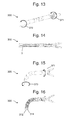
- FIG. 12 is an enlarged view, in an exploded perspective view, of the portion referenced as A of the surgical instrument of FIG. 11 ;
- FIG. 13 is a perspective view of the surgical instrument of FIG. 11 , the distal end being in a straight position;
- FIG. 14 is a cross sectioned view of the surgical instrument of FIG. 11 , the distal end being in a straight position;
- FIG. 15 is a perspective view of the surgical instrument of FIG. 11 , the distal end being in a fully folded position;
- FIG. 16 is a cross sectioned view of the surgical instrument of FIG. 11 , the distal end being in a fully folded position;
- FIG. 17 is a perspective view which represents the transmissions system and handle of the surgical instrument.
- FIG. 1 illustrates the distal part of a surgical instrument 1 according to a first embodiment of the invention.
- the surgical instrument 1 comprises an elongated arm 11 , here in a cylindrical revolution shape according to a longitudinal axis (not shown).
- the elongated arm is hollow and has, on a distal part, an opening on a semi-circumference terminating longitudinally via linking means comprising an axis 10 substantially orthogonal to the longitudinal axis of the elongated arm 11 and extending according to a diameter of a section of said elongated arm 11 .
- linking means connect the elongated arm to a distal end 2 comprising, in this respect, complementary linking means. This forms a pivot joint between the elongated arm 11 and the distal end 2 .
- the distal end 2 here is hollow, cylindrical in revolution in shape about an axis and open on a semi-circumference approximately over the entire length of the distal end 2 , except at the level of an end face 12 .
- the section of the distal end 2 is almost identical to that of the elongated arm 11 . Accordingly, in an unfolded position, as illustrated in FIGS. 1 and 2 , the distal end 2 extends in the longitudinal extension of the elongated arm 11 , the longitudinal axis of the elongated arm 11 coinciding with the axis of the distal end 2 .
- the end face 12 comprises a section of a shaft extending in projection towards the exterior along the axis of the distal end 2 .
- a distal tool 9 here a forceps, is mounted in rotation on the section of shaft of the end face 12 , in an extension according to the axis of the distal end 2 .
- the elongated arm 11 At the level of a proximal end, the elongated arm 11 comprises an end face comprising an axial bore 13 , the longitudinal axis of the elongated arm 11 .
- the surgical instrument 1 comprises a drive shaft 3 which extends in the elongated arm 11 from the bore 13 to the distal tool 9 with which it is solid to be able to drive it in a rotation movement about its axis.
- the drive shaft 3 here is free to turn according to its axis and slide according to a translation movement relative to the elongated arm 11 axis.
- the drive shaft 3 comprises, at its distal end, means forming a universal joint 4 , 5 , 6 , 7 and 8 which extend, as shown in FIG. 1 , into the openings made on a semi-circumference of the distal end 2 and of the elongated arm 11 .
- the universal joint is thus facing the pivot joint, that is it is arranged to accompany the rotational movement of the pivot joint.
- the means forming universal joint comprise a first Cardan joint 4 , 5 mounted in series with a second Cardan joint 7 , 8 by a portion 6 of the drive shaft.
- a Cardan joint refers to a mechanical linking system comprising two and elements mounted on either side of a central element, where each end element is mounted in a pivot joint with the central element.
- the axes of the two pivot joints between the central element and the two end elements respectively are perpendicular (that is, orthogonal and secant) and therefore join at the same point, enabling transmission of angular rotation movement between two shafts extending respectively from the end elements.
- the Cardan joints comprise a central piece in the form of a brace, the branches of the brace forming axes on which the end pieces 4 , 5 and 7 , 8 are mounted in a pivot joint.
- the function fulfilled by the distal tool 9 is controlled by a cable which extends inside the drive shaft 3 which is hollow for this purpose.
- the cable is made of resistant metal but still remains sufficiently flexible to follow the movement of the distal end 2 when the pivot joint is used about the axis 10 .
- FIG. 3 a illustrates the folded position at around 90°
- FIG. 3 b illustrates the unfolded position
- rotation movement 15 applied to the proximal end of the drive shaft causes a rotation movement 14 of the distal tool 9 .
- a perfect transmission of this rotation movement is ensured by the means forming a universal joint, and this being irrespective of the degree of folding of the distal end 2 turning about the axis 10 of the pivot joint.
- a transition from the folded position to the unfolded position (or between two different folded positions) occurs via translation movement of the drive shaft 3 according to its axis.
- this translation movement modifies the distance between the axis 10 of the pivot joint between the elongated arm 1 and the distal end 2 and orthogonal projection of any point of the distal tool 9 on the axis of the elongated arm 11 .
- the rigidity of the distal end 11 causes a rotation movement about the axis 10 to produce a folded position (or unfolded), the drive shaft following the movement as a result of the means forming a universal joint.
- the surgical instrument 100 comprises an elongated arm 111 , here cylindrical in revolution in shape according to a longitudinal axis (not shown).
- the elongated arm 111 distally comprises a base linking element 101 comprising an axis 110 substantially perpendicular to the longitudinal axis of the elongated arm 111 .
- the elongated arm 111 further comprises a second linking element 102 comprising a bore 112 at a proximal end and an axis 110 similar to the axis 110 of the base linking element 101 and situated at a distal end of the second linking element 102 .
- the second linking element 102 is mounted in rotation on the base linking element 101 by cooperation of the axis 110 of the base linking element 101 and the bore 112 of the second linking element 102 , thus forming a pivot joint.
- the elongated arm 111 further comprises a third linking element 105 comprising, at a proximal end, a bore 112 similar to the bore 112 of the second linking element 102 .
- the third linking element 105 is mounted in rotation on the second linking element 102 by cooperation of the axis 110 of the second linking element 102 with the bore of the third linking element 105 , thus forming a second pivot joint.
- This third linking element 105 forms the distal end of the elongated arm 111 .
- the distal tool 9 mounted on a distal end of the third linking element is the distal tool 9 , here a forceps, in an extension of the third linking element 105 .
- the latter is mounted in rotation about a longitudinal axis of the third linking element 105 on the latter.
- several linking elements 102 can be mounted in series between the base linking element 101 and the third linking element 105 bearing the distal tool 9 .
- the distal tool 9 is mounted in rotation on and in the extension of the distal end of the elongated arm 111 .
- the distal end of the elongated arm 111 formed by the third linking element 105 is mounted according to a pivot joint on the latter.
- the surgical instrument 100 comprises a drive shaft 103 which extends about the elongated arm 111 from substantially a proximal end of said elongated arm 111 and substantially a proximal part of the base linking element 101 .
- a drive sleeve 104 is mounted firmly on a distal end of the drive shaft 103 in the extension of the latter.
- the drive sleeve 104 is mounted on the distal tool 9 so as to drive it in rotation movement about its axis.
- the drive sleeve 104 is arranged to extend about the base linking element 101 , of the second linking element(s) 102 and of the third linking element 105 , once mounted, as illustrated in FIG. 5 .
- the drive shaft 103 and consequently the sleeve 104 , is free to turn according to its axis relative to the elongated arm 111 .
- the drive sleeve 104 forms means forming a universal joint.
- the drive sleeve 104 is rigid with regard to torsion stress according to the longitudinal axis, and is flexible and deformable elastically with regards to torsion stress according to any axis perpendicular to the longitudinal axis.
- Torsion according to an axis corresponds to the twisting about such axis produced by the action of two opposing couples acting in parallel planes.
- the drive sleeve comprises bellows which is rigid with regard to torsion stress according to the longitudinal axis, so as to transmit the rotation movement about this axis of the drive shaft 103 to the distal tool 9 , and which is flexible and deformable elastically with regard to torsion stress according to any axis perpendicular to the longitudinal axis, so as to deform easily when pivot joints are used between the base linking element 101 and second 102 and third 105 linking elements (cf. FIGS. 6 a and 6 b ).
- the bellows may for instance be metallic. Any other adapted material can be used to make said bellows.
- the function fulfilled by the distal tool 9 is controlled by actuating cable 205 , which extends inside the drive shaft 3 which is hollow, for this purpose.
- the cable is made of resistant metal but still remains sufficiently flexible to follow the movement of the distal end when pivot joints are used about axes 210 .
- using pivot joints between the base linking element 201 and second 202 , 203 and third 204 linking elements is achieved by means of a cable 212 (cf. FIGS. 10 a and 10 b ) extending inside the elongated arm 207 from the proximal part of the base linking element 201 .
- the cable 212 comprises a distal end 211 securely fastened with the third linking element 204 .
- Part 214 of the cable extends outside the elongated arm 207 , opposite the second linking elements 202 , 203 . Traction force 213 on the cable utilises the above pivot joints, as is illustrated in FIG. 10 b .
- a second cable can be used, located diametrically opposite the cable 212 .
- the part 214 of the cable extends inside the second linking elements (if a second cable is used, the latter can also extend inside the second linking elements).
- These different cables can be enclosed by a sheath which protects them, but which also allows the length of the cable or cables placed according to the principal axis of insertion to be independent of the flexion of the surgical instrument and force these cables to follow curvature of the principal axis. This avoids for instance that pulling cable actuating distal tool 9 creates forces on the surrounding structure when distal tool 9 is pivoted with respect to elongated arm 207 .
- FIG. 6 b ( 7 b ) illustrates the folded position at around 90°
- FIG. 6 a ( 7 a ) illustrates the unfolded position
- a rotation movement 120 applied to the proximal end of the drive shaft causes rotation movement 121 of the distal tool 9
- Perfect transmission of this rotation movement is ensured by the means forming a universal joint (drive sleeve 104 ) and, this being irrespective of the degree of folding of the distal end turning about axes 110 of the pivot joints.
- Transition from the folded position to the unfolded position (or between two different folded positions) occurs via translation movement 135 of one of the cables 130 , 131 according to its axis.
- An operator controls orientation of the distal tool 9 by moving one of these cables according to this translation movement.
- the surgical instrument 200 comprises an elongated arm 207 , here cylindrical in revolution in shape according to a longitudinal axis (not shown).
- the elongated arm 207 is hollow and distally comprises a base linking element 201 hollow, comprising two lugs extending in the extension of the elongated arm 207 and opposite one another to define an axis 210 substantially perpendicular to the longitudinal axis of the elongated arm 207 .
- the elongated arm 207 further comprises second hollow linking elements 202 , 203 (also called intermediate linking elements), comprising two lugs extending in the extension of said second linking elements 202 , 203 and opposite one another to define an axis 210 similar to the axis 210 of the base linking element 201 and located at a distal end of the second linking elements 202 , 203 .
- the second linking element 202 is mounted in rotation relative to the axis 210 on the base linking element 201 , thus forming a pivot joint.
- the second linking elements 202 and 203 are mounted in rotation relative to their mutual axis 210 , thus forming a second pivot joint.
- the elongated arm 207 further comprises a third hollow linking element 204 (also called and linking element). Similarly, the third linking element 204 is mounted in rotation relative to the axis 210 on the second linking element 203 , thus forming a third pivot joint. This third linking element 204 forms the distal end of the elongated arm 207 .
- the distal tool 9 is mounted on a distal end of the third linking element 204 .
- the distal tool 9 is mounted in rotation about a longitudinal axis of the third linking element 204 on the latter.
- more than two linking elements 202 , 203 can be mounted in series between the base linking element 201 and the third linking element 204 bearing the distal tool 9 .
- the distal tool 9 is mounted in rotation on and in the extension of the distal end of the elongated arm 207 .
- the distal end of the elongated arm 207 formed by the third linking element 204 is mounted according to a pivot joint on the latter.
- the third linking element 204 is mounted directly in series on the base linking element 201 .
- a single second linking element 202 is mounted in series between the third linking element 204 and the base linking element 201 .
- linking elements are segmented elements which, when mounted in series, fulfil the pivot function.
- This assembly of linking elements can be similar to a set of hollow vertebrae of substantially cylindrical form, each of the vertebrae being mounted with the preceding vertebra with a pivot joint according to a pivot axis 210 perpendicular to the longitudinal axis of the elongated arm 207 .
- Such pivot joint is also referred as a limited pivot joint or wedged pivot joint, as the angular amplitude of the pivot is structurally restricted by the form of the linking elements.
- All the axes of the pivot joints 210 are parallel such that the total angle of flexion is the sum of the angles of rotation between each pair of vertebrae.
- the series of the limited pivot joints produces an accumulative pivot with respect to the whole body, which corresponds to the overall pivot joint.
- the hollow vertebrae have a substantially cylindrical form. They can be assembled with others like puzzle pieces, by having one piece slide relative to the other according to the axis of the pivot 210 . Accordingly it is not necessary to provide a rod to physically form the pivot joint which is in reality ensured by cooperation of the lugs of each vertebra with a complementary form arranged on the following vertebra, this complementary form for example being a notch made from the edge of the cylinder forming the vertebra. Such an arrangement considerably simplifies assembling of the assembly.
- such a configuration also has the advantage of forming a pivot joint without introducing dents or additional structure in the internal wall or in the external wall of the vertebra, ensuring no loss of room inside the vertebra on the one hand, and on the other hand ensuring a smooth surgical instrument without an element which might impede its displacement in the insertion trocar of the surgical instrument.
- the vertebrae are kept in a nested position in one another by any means, but will preferably be held by the actuating cables of the pivot joints passing through the vertebrae, and/or the elements placed inside the vertebrae and ensuring this position is kept especially by overlapping of the pieces.
- Ensuring the pivot function by a set of vertebrae such as described hereinabove has numerous advantages.
- specific assembling by nesting/puzzle, and even by clipping
- the proposed arrangement uses small-sized pieces and guarantees an outer diameter of the surgical instrument of the order of 5 mm, ensuring considerable angular amplitude of the pivot and satisfactory rigidity of the assembly for manipulation of the surgical instrument.
- using a series of successive vertebrae easily produces the angular amplitude generally used of the order of 90°, since each pivot between two successive vertebrae permits angular amplitude of at least 20° (corresponding to what qualifies as a limited pivot joint).
- the proposed arrangement ensures the required rigidity for good manipulation of the surgical instrument, especially torsional rigidity according to the axes orthogonal to the axis of the overall pivot, this being due especially to the full cylindrical form of the vertebrae and to their particular coupling.
- the fact that the axes of the pivots 210 are perpendicular to the longitudinal axis of the elongated arm 207 allows the lugs of the vertebrae to be arranged in the body of the cylinder according to a diametrical axis, preventing them from projecting relative to the outer wall of said cylinder.
- the surgical instrument 200 mounted substantially coaxially with the elongated arm 207 , the surgical instrument 200 according to the embodiment presented in FIGS. 8 to 10 comprises a drive shaft 3 which extends in the elongated arm 207 from substantially a proximal end of said elongated arm 207 and substantially a proximal part of the base linking element 201 .
- a drive sleeve 206 is mounted solid on a distal end of the drive shaft 3 in the extension of the latter. The drive sleeve 206 is securely fastened with the distal tool 9 so as to drive it in rotation movement about its axis.
- the drive sleeve 206 is arranged to extend within the base linking element 201 , the second linking elements 202 , 203 and the third linking element 204 , once mounted, as illustrated in FIG. 9 .
- the drive shaft 3 and consequently the sleeve 206 , is free to turn according to its axis relative to the elongated arm 207 .
- the drive sleeve 206 forms means forming a universal joint.
- the flexible drive sleeve is rigid with regard to torsion stress according to the longitudinal axis, and is flexible and deformable elastically with regard to torsion stress according to any axis perpendicular to the longitudinal axis. In the embodiment of FIGS.
- the drive sleeve comprises bellows which are rigid with regard to torsion stress according to the longitudinal axis, so a to transmit rotation movement about this axis of the drive shaft 3 to the distal tool 9 , and flexible and deformable elastically with regard to torsion stress according to any axis perpendicular to the longitudinal axis, so as to deform easily when pivot joints are used between the base linking element 201 and second 202 , 203 and third 204 linking elements.
- the bellows may for instance be metallic. Any other adapted material can be used to make said bellows.
- the function fulfilled by the distal tool 9 is controlled by a cable which extends inside the drive shaft 3 which is hollow, for this purpose.
- the cable is made of resistant metal but still remains sufficiently flexible to follow the movement of the distal end when pivot joints are used about axes 210 .
- using pivot joints between the base linking element 201 and second 202 , 203 and third 204 linking elements is achieved by means of a cable 212 (cf. FIGS. 10 a and 10 b ) extending inside the elongated arm 207 from the proximal part of the base linking element 201 .
- the cable 212 comprises a distal end 211 securely fastened with the third linking element 204 .
- Part 214 of the cable extends outside the elongated arm 207 , opposite the second linking elements 202 , 203 . Traction force 213 on the cable utilises the above pivot joints, as is illustrated in FIG. 10 b .
- a second cable can be used, located diametrically opposite the cable 212 .
- the part 214 of the cable extends inside the second linking elements (if a second cable is used, the latter can also extend inside the second linking elements).
- These different cables can be enclosed by a sheath which protects them, but which also allows the length of the cable or cables placed according to the principal axis of insertion to be independent of the flexion of the surgical instrument and force these cables to follow curvature of the principal axis. This avoids for instance that pulling cable actuating distal tool 9 creates forces on the surrounding structure when distal tool 9 is pivoted with respect to elongated arm 207 .
- FIG. 10 b illustrates the folded position at around 90°
- FIG. 10 a illustrates the unfolded position
- rotation movement applied to the proximal end of the drive shaft causes rotation movement of the distal tool 9 .
- Perfect transmission of this rotation movement is ensured by the means forming a universal joint (drive sleeve 206 ) and, this being irrespective of the degree of folding of the distal end turning about axes 210 of the pivot joints.
- Transition from the folded position to the unfolded position is done via translation movement 213 of the cable 212 according to its axis.
- An operator controls the orientation of the distal tool 9 by moving this cable according to this translation movement.
- the surgical instrument 300 comprises an elongated arm 307 having a form similar to the elongated arm 207 of the surgical instrument 200 according to the third embodiment of the invention.
- the elongated arm 307 comprises one or more linking elements making up the pivot function, where the set of linking elements can be similar to a set of hollow vertebrae, each of the vertebrae being mounted according to an axis pivot joint perpendicular to the axis of the elongated arm with the preceding vertebra.
- the elongated arm 307 comprises five linking elements ( 301 , 302 , 303 , 304 , 305 ) forming the pivot joint (also called overall pivot joint).
- the elongated arm 307 is hollow and distally comprises a hollow base linking element 301 , comprising one set of pivot lugs (female side only) extending in the direction of the elongated arm 307 and opposite one another to define an axis 310 substantially perpendicular to the longitudinal axis of the elongated arm 307 .
- the elongated arm 307 further comprises hollow intermediate linking elements ( 302 , 303 , 304 ), comprising two lugs extending in the extension of said intermediate linking elements ( 302 , 303 , 304 ) and opposite one another to enable rotation about an axis parallel to the axis 310 of the base linking element 301 and located at a distal end of the intermediate linking elements ( 302 , 303 , 304 ).
- the intermediate linking element 302 is mounted in rotation relative to the axis 310 on the base linking element 301 , thus forming a first limited pivot joint (also called wedged pivot joint, as the form of the linking elements naturally restrict the amplitude of the pivot).
- the intermediate linking elements ( 302 , 303 , 304 ) are mounted in mutual rotation relative to the axis 310 , thus forming a second and third limited pivot joint.
- the elongated arm 307 further comprises a hollow end linking element 305 .
- the end linking element 305 is mounted in rotation relative to the axis 310 on the final intermediate linking element 304 , thus forming a fourth limited pivot joint.
- This end linking element 305 forms the distal end of the elongated arm 307 .
- the series of the limited pivot joints produces an accumulative pivot with respect to the whole body, which corresponds to the overall pivot joint. All the axes of the pivot joints 310 are parallel such that the total angle of flexion is the sum of the angles of rotation between each pair of linking elements.
- the vertebrae are pierced to allow two cables ( 312 , 314 ) placed on either side of the axis of the pivot 310 to slide.
- the cables ( 312 , 314 ) are attached to the final vertebra and slide in the openings of the others, which allow all the pivots to be actuated after mounting and therefore flexes by pulling on one or the other of the two cables ( 312 , 314 ).
- the surgical instrument 300 comprises a drive shaft 3 which extends in the elongated arm 307 from substantially a proximal end of said elongated arm 307 to substantially a proximal part of the base linking element 301 .
- the drive shaft 3 comprises, at its distal end, means forming a universal joint which extend in the cavity formed by the different linking elements, these means forming a universal joint comprising at least one Cardan joint.
- the means forming a universal joint preferably comprise at least two Cardan joints.
- the means forming a universal joint more preferably comprise as many Cardan joints as pivot axes 310 formed by the vertebrae ( 301 , 302 , 303 , 304 , 305 ).
- the means forming a universal joint more preferably comprise as many Cardan joints as pivot axes 310 formed by the vertebrae ( 301 , 302 , 303 , 304 , 305 ).
- four Cardan joints ( 320 , 330 , 340 , 350 ) are provided, respectively positioned at the level of the pivot axes 310 formed between the different linking elements ( 301 , 302 , 303 , 304 , 305 ), that is adjacent to the corresponding pivot joint.
- the axes of the two pivot joints defining each Cardan joint intersect with the pivot axis 310 at the level where it is positioned.
- a Cardan joint is a mechanical linking system comprising two end elements mounted on either side of a central element, where each end element is mounted in a pivot joint with the central element.
- the pivot joints between the pieces forming the Cardan joint are made by a sliding guide of one surface on another.
- end pieces having at their end of the surfaces sliding on the surface of the central piece can be provided for example, these central and end pieces also comprising sliding guide means.
- the central piece 322 of the Cardan joint 320 is preferably a sphere in which two grooves are hollowed out in two perpendicular diametrical planes, preferably according to two diametrical circles. More preferably, each groove forms a circle around the sphere.
- the end pieces 321 and 323 have as such ends formed to be able to slide on the sphere 322 , having hollow/concave surfaces with for example a semi-cylindrical or semi-spherical form complementary to the sphere 322 .
- the contact surfaces at the ends of the end pieces 321 and 323 also preferably comprise a ridge in projection whereof, said ridge having a form corresponding to the geometry of the hollow grooves in the sphere 322 , such that the ridge in projection serves as guide rail for sliding of the end pieces 321 and 323 on the central piece 322 .
- the end pieces 321 and 323 also have a general cylinder form.
- two successive Cardan joint could have a common end piece (corresponding to the end piece positioned between the two spheres of the two Cardan joints) having the form of a cylinder with at its two ends a hollow surface formed for sliding on the spheres.
- shoulders preferably prevent the sliding according to the axis of the drive shaft 3 and the contact between the sliding surfaces is maintained by external pressure, due especially to the mechanical assembling of the different pieces.
- the spheres are preferably placed such that their centre belongs to the pivot axis of the vertebrae, such that the axes of the pivot joint made by the contact surfaces intersect the pivot axis of the vertebrae. All the pieces forming the Cardan joints are small enough to be nestled inside the vertebrae.
- the outer diameter of the cylinders forming the and pieces of the Cardan joints is preferably adjusted to the inner diameter of the vertebrae so that the cylinders can slide inside the vertebrae, thus facilitating assembling of the assembly, since the cylinders and spheres forming the Cardan joints can be inserted and slide inside the vertebrae according to the longitudinal axis of the elongated arm 307 .
- Assembling such a set of Cardan joints therefore consists of inserting in the vertebrae ( 301 , 302 , 303 , 304 , 305 ) and stacking between them a succession of cylindrical elements and spherical elements, respectively forming the end elements and central elements of the Cardan joints ( 320 , 330 , 340 , 350 ). Accordingly, the ridge in projection of a cylinder is inserted into the groove of the sphere in which the ridge in projection of the preceding cylinder is not inserted, the ridges in projection of two consecutive cylinders in contact with the sphere connecting it therefore being orthogonal. It is ensured that the centre of the spheres is positioned according to the pivot axis of the corresponding vertebrae.
- the assembly is then blocked in translation by the stacked axis corresponding to the longitudinal axis of the elongated arm 307 , by a screw system, for example.
- Transmission of the intrinsic rotation of the distal part is then possible between the most proximal cylinder and the most distal cylinder by relative shifts of the cylinders and of these spheres which respect Cardan kinematics.
- transmission can overall remain homokinetic if, for each intermediate cylinder, the ridges in projection of the ends are machined orthogonally relative to one another, and if the number of Cardan joints is even.
- a distal tool 9 for example a forceps, is mounted on a distal end of the end linking element 305 , in its extension.
- the distal tool 9 is mounted in rotation about a longitudinal axis of the element end linking element 305 on the latter.
- This distal tool 9 is preferably actuated by a cable extending inside the elongated arm 307 . More preferably, the cylindrical and spherical pieces forming the transmission by Cardan joints are pierced by through-holes according to the principal axis of the instrument when the latter is not flexed.
- a flexible mechanical cable 360 to pass through for transmission of traction force to actuate the distal tool 9 placed at the distal end of the instrument, or of electric cables (not shown) for transmission of a signal, a command or a monopolar and/or bipolar current.
- This or these cables are preferably enclosed by a sheath 361 which on the one hand protects this or these cables, but also the length of the cable or cables placed according to the principal axis of insertion is independent of the flexion of the surgical instrument and force these cables to follow curvature of the principal axis. This avoids for instance that pulling cable actuating distal tool 9 creates forces on the surrounding structure when distal tool 9 is pivoted with respect to elongated arm 207 .
- FIGS. 15 and 16 illustrate the folded position at 90°, while FIGS. 13 and 14 illustrate the unfolded position.
- a rotation movement 370 applied to the proximal end of the drive shaft causes rotation movement 371 of the distal tool 9 .
- Perfect transmission of this rotation movement is ensured by the means forming a universal joint (Cardan joints 320 , 330 , 340 , 350 ) and, this being irrespective of the angular deflection of the distal end turning about axes 310 of the limited pivot joints.
- the transition of the folded position to the unfolded position occurs via translation movement of one of the cables 312 , 314 according to its axis. An operator controls the orientation of the distal tool 9 by moving one of these cables according to this translation movement.
- Controlling of the different cables used in the described surgical instrument could be done manually by the user, or by means of one or more motors automating operation of the surgical instrument.
- a motor can also be used to set the drive shaft in rotation about its longitudinal axis.
- the described surgical instrument distinguishes itself from existing instruments by having distal mobility in that the intrinsic rotation movement of the forceps is completely independent of the other movements (especially those which orient the axis of the forceps relative to the principal axis of the instrument) and transmitted directly via rotation movement carried out at the level of the proximal part.
- this allows control of two movements of the distal part from two independent movements engendered at the level of the handle 381 via drive shaft 3 , which are orientation of the axis of the forceps clue to rotation about an axis substantially orthogonal to the axis of insertion of the instrument and rotation about the axis of the forceps.
Abstract
-
- an elongated arm (111; 207) according to a longitudinal axis and having a distal end (105; 204) mounted with a pivot joint on the elongated arm according to an axis substantially orthogonal to the longitudinal axis;
- a drive shaft (103; 3), substantially coaxial with the elongated arm, comprising means forming a universal joint (104; 206) facing the pivot joint; and,
- distal tool (9) securely fastened on the drive shaft and rotatively mounted on and in the extension of the distal end of the elongated arm, such that the distal tool has two rotational degrees of freedom, distinct and independent of each other, one being around an axis substantially perpendicular to the longitudinal axis of the elongated arm and the other being around an axis substantially collinear to an own axis of the distal tool, characterized in that the means forming a universal joint comprise a flexible drive sleeve (104; 206).
Description
-
- 1. grasps the needle such that the plane of the needle is perpendicular to the axis of the forceps;
- 2. places the plane of the needle perpendicularly to he edges to be sutured;
- 3. turns the needle according to an axis perpendicular to its plane to insert into the tissue to be sutured.
-
- an elongated arm according to a longitudinal axis and having a distal end mounted with a pivot joint on the elongated arm according to an axis substantially orthogonal to the longitudinal axis;
- a drive shaft, substantially coaxial with the elongated arm, comprising means forming a universal joint facing the pivot joint; and,
- a distal tool securely fastened on the drive shaft and rotatively mounted on and in the extension of the distal end of the elongated arm, such that the distal tool has two rotational degrees of freedom, distinct and independent of each other, one being around an axis substantially perpendicular to the longitudinal axis of the elongated arm and the other being around an axis substantially collinear to an own axis of the distal tool, characterised in that the means forming a universal joint comprise a flexible drive sleeve.
-
- the flexible drive sleeve comprises bellows.
- the flexible drive sleeve is rigid with regard to torsion stress according to the longitudinal axis, and is flexible and elastically deformable with regard to torsion stress according to any axis perpendicular to the longitudinal axis.
- the pivot joint comprises a plurality of linking elements mounted in series.
- two adjacent linking elements are mounted relative to one another according to a limited pivot joint.
- each linking element is a hollow cylindrical element comprising two lugs extending towards the adjacent linking element, said lugs being opposite one another to define the limited pivot joint.
- the elongated arm is hollow and at least partially encloses the drive shaft.
- the drive shaft is hollow and at least partially encloses the elongated arm.
- the elongated arm comprises a through-hole along the longitudinal axis, one or more cables extending in the elongated arm via the through-hole.
- the surgical instrument comprises an actuating cable of the distal tool extending along the longitudinal axis, the actuating cable being surrounded by a sheath.
- the surgical instrument further comprises a handle and a transmission system, wherein the handle is connected to the proximal end of the elongated arm, the movements according to the two degrees of freedom being connected by the transmission system to two independent movements produced at the handle.
- the surgical instrument is arranged such that the amplitude of rotation of the tool about its own axis is not limited structurally by the transmission system.
Claims (12)
Applications Claiming Priority (3)
| Application Number | Priority Date | Filing Date | Title |
|---|---|---|---|
| FR0952185A FR2943906B1 (en) | 2009-04-03 | 2009-04-03 | SURGICAL INSTRUMENT. |
| FR0952185 | 2009-04-03 | ||
| PCT/EP2010/054470 WO2010112608A1 (en) | 2009-04-03 | 2010-04-02 | Surgical instrument |
Publications (2)
| Publication Number | Publication Date |
|---|---|
| US20120083770A1 US20120083770A1 (en) | 2012-04-05 |
| US8845622B2 true US8845622B2 (en) | 2014-09-30 |
Family
ID=41268407
Family Applications (1)
| Application Number | Title | Priority Date | Filing Date |
|---|---|---|---|
| US13/260,910 Active US8845622B2 (en) | 2009-04-03 | 2010-04-02 | Surgical instrument |
Country Status (5)
| Country | Link |
|---|---|
| US (1) | US8845622B2 (en) |
| EP (1) | EP2413819B1 (en) |
| JP (1) | JP2012522553A (en) |
| FR (1) | FR2943906B1 (en) |
| WO (1) | WO2010112608A1 (en) |
Cited By (228)
| Publication number | Priority date | Publication date | Assignee | Title |
|---|---|---|---|---|
| US20120022554A1 (en) * | 2009-04-03 | 2012-01-26 | Jamie Paik | Surgical instrument |
| US10092359B2 (en) | 2010-10-11 | 2018-10-09 | Ecole Polytechnique Federale De Lausanne | Mechanical manipulator for surgical instruments |
| US10265129B2 (en) | 2014-02-03 | 2019-04-23 | Distalmotion Sa | Mechanical teleoperated device comprising an interchangeable distal instrument |
| US10325072B2 (en) | 2011-07-27 | 2019-06-18 | Ecole Polytechnique Federale De Lausanne (Epfl) | Mechanical teleoperated device for remote manipulation |
| US10357320B2 (en) | 2014-08-27 | 2019-07-23 | Distalmotion Sa | Surgical system for microsurgical techniques |
| US10363055B2 (en) | 2015-04-09 | 2019-07-30 | Distalmotion Sa | Articulated hand-held instrument |
| US10413374B2 (en) | 2018-02-07 | 2019-09-17 | Distalmotion Sa | Surgical robot systems comprising robotic telemanipulators and integrated laparoscopy |
| US10548680B2 (en) | 2014-12-19 | 2020-02-04 | Distalmotion Sa | Articulated handle for mechanical telemanipulator |
| US10568709B2 (en) | 2015-04-09 | 2020-02-25 | Distalmotion Sa | Mechanical teleoperated device for remote manipulation |
| US10646294B2 (en) | 2014-12-19 | 2020-05-12 | Distalmotion Sa | Reusable surgical instrument for minimally invasive procedures |
| US10786272B2 (en) | 2015-08-28 | 2020-09-29 | Distalmotion Sa | Surgical instrument with increased actuation force |
| US20200337791A1 (en) * | 2012-06-28 | 2020-10-29 | Ethicon Llc | Surgical end effectors having angled tissue-contacting surfaces |
| US10864049B2 (en) | 2014-12-19 | 2020-12-15 | Distalmotion Sa | Docking system for mechanical telemanipulator |
| US10864052B2 (en) | 2014-12-19 | 2020-12-15 | Distalmotion Sa | Surgical instrument with articulated end-effector |
| US10905505B1 (en) | 2016-04-22 | 2021-02-02 | Memorial Sloan Kettering Cancer Center | Robotic surgical manipulation systems and methods |
| US10960182B2 (en) | 2016-02-05 | 2021-03-30 | Board Of Regents Of The University Of Texas System | Steerable intra-luminal medical device |
| US11039820B2 (en) | 2014-12-19 | 2021-06-22 | Distalmotion Sa | Sterile interface for articulated surgical instruments |
| US11058503B2 (en) | 2017-05-11 | 2021-07-13 | Distalmotion Sa | Translational instrument interface for surgical robot and surgical robot systems comprising the same |
| US11399831B2 (en) | 2014-12-18 | 2022-08-02 | Cilag Gmbh International | Drive arrangements for articulatable surgical instruments |
| US11419606B2 (en) | 2016-12-21 | 2022-08-23 | Cilag Gmbh International | Shaft assembly comprising a clutch configured to adapt the output of a rotary firing member to two different systems |
| US11426167B2 (en) | 2019-06-28 | 2022-08-30 | Cilag Gmbh International | Mechanisms for proper anvil attachment surgical stapling head assembly |
| US11426160B2 (en) | 2015-03-06 | 2022-08-30 | Cilag Gmbh International | Smart sensors with local signal processing |
| US11439470B2 (en) | 2011-05-27 | 2022-09-13 | Cilag Gmbh International | Robotically-controlled surgical instrument with selectively articulatable end effector |
| US11446029B2 (en) | 2019-12-19 | 2022-09-20 | Cilag Gmbh International | Staple cartridge comprising projections extending from a curved deck surface |
| US11446034B2 (en) | 2008-02-14 | 2022-09-20 | Cilag Gmbh International | Surgical stapling assembly comprising first and second actuation systems configured to perform different functions |
| US11452526B2 (en) | 2020-10-29 | 2022-09-27 | Cilag Gmbh International | Surgical instrument comprising a staged voltage regulation start-up system |
| US11457918B2 (en) | 2014-10-29 | 2022-10-04 | Cilag Gmbh International | Cartridge assemblies for surgical staplers |
| US11464514B2 (en) | 2008-02-14 | 2022-10-11 | Cilag Gmbh International | Motorized surgical stapling system including a sensing array |
| US11464601B2 (en) | 2019-06-28 | 2022-10-11 | Cilag Gmbh International | Surgical instrument comprising an RFID system for tracking a movable component |
| US11464512B2 (en) | 2019-12-19 | 2022-10-11 | Cilag Gmbh International | Staple cartridge comprising a curved deck surface |
| US11471155B2 (en) | 2017-08-03 | 2022-10-18 | Cilag Gmbh International | Surgical system bailout |
| US11478244B2 (en) | 2017-10-31 | 2022-10-25 | Cilag Gmbh International | Cartridge body design with force reduction based on firing completion |
| US11478241B2 (en) | 2019-06-28 | 2022-10-25 | Cilag Gmbh International | Staple cartridge including projections |
| US11484309B2 (en) | 2015-12-30 | 2022-11-01 | Cilag Gmbh International | Surgical stapling system comprising a controller configured to cause a motor to reset a firing sequence |
| US11484310B2 (en) | 2017-06-28 | 2022-11-01 | Cilag Gmbh International | Surgical instrument comprising a shaft including a closure tube profile |
| US11484312B2 (en) | 2005-08-31 | 2022-11-01 | Cilag Gmbh International | Staple cartridge comprising a staple driver arrangement |
| US11484311B2 (en) | 2005-08-31 | 2022-11-01 | Cilag Gmbh International | Staple cartridge comprising a staple driver arrangement |
| US11484307B2 (en) | 2008-02-14 | 2022-11-01 | Cilag Gmbh International | Loading unit coupleable to a surgical stapling system |
| US11490889B2 (en) | 2015-09-23 | 2022-11-08 | Cilag Gmbh International | Surgical stapler having motor control based on an electrical parameter related to a motor current |
| US11497499B2 (en) | 2016-12-21 | 2022-11-15 | Cilag Gmbh International | Articulatable surgical stapling instruments |
| US11497492B2 (en) | 2019-06-28 | 2022-11-15 | Cilag Gmbh International | Surgical instrument including an articulation lock |
| US11497488B2 (en) | 2014-03-26 | 2022-11-15 | Cilag Gmbh International | Systems and methods for controlling a segmented circuit |
| US11504122B2 (en) | 2019-12-19 | 2022-11-22 | Cilag Gmbh International | Surgical instrument comprising a nested firing member |
| US11504116B2 (en) | 2011-04-29 | 2022-11-22 | Cilag Gmbh International | Layer of material for a surgical end effector |
| US11504144B2 (en) | 2016-02-05 | 2022-11-22 | Board Of Regents Of The University Of Texas System | Surgical apparatus |
| US11504197B1 (en) | 2021-03-31 | 2022-11-22 | Moon Surgical Sas | Co-manipulation surgical system having multiple operational modes for use with surgical instruments for performing laparoscopic surgery |
| US11504119B2 (en) | 2013-08-23 | 2022-11-22 | Cilag Gmbh International | Surgical instrument including an electronic firing lockout |
| US11517304B2 (en) | 2008-09-23 | 2022-12-06 | Cilag Gmbh International | Motor-driven surgical cutting instrument |
| US11517311B2 (en) | 2014-12-18 | 2022-12-06 | Cilag Gmbh International | Surgical instrument systems comprising an articulatable end effector and means for adjusting the firing stroke of a firing member |
| US11517306B2 (en) | 2016-04-15 | 2022-12-06 | Cilag Gmbh International | Surgical instrument with detection sensors |
| US11517325B2 (en) | 2017-06-20 | 2022-12-06 | Cilag Gmbh International | Closed loop feedback control of motor velocity of a surgical stapling and cutting instrument based on measured displacement distance traveled over a specified time interval |
| US11517390B2 (en) | 2020-10-29 | 2022-12-06 | Cilag Gmbh International | Surgical instrument comprising a limited travel switch |
| US11523821B2 (en) | 2014-09-26 | 2022-12-13 | Cilag Gmbh International | Method for creating a flexible staple line |
| US11523823B2 (en) | 2016-02-09 | 2022-12-13 | Cilag Gmbh International | Surgical instruments with non-symmetrical articulation arrangements |
| US11523822B2 (en) | 2019-06-28 | 2022-12-13 | Cilag Gmbh International | Battery pack including a circuit interrupter |
| US11529140B2 (en) | 2017-06-28 | 2022-12-20 | Cilag Gmbh International | Surgical instrument lockout arrangement |
| US11529138B2 (en) | 2013-03-01 | 2022-12-20 | Cilag Gmbh International | Powered surgical instrument including a rotary drive screw |
| US11529139B2 (en) | 2019-12-19 | 2022-12-20 | Cilag Gmbh International | Motor driven surgical instrument |
| US11529142B2 (en) | 2010-10-01 | 2022-12-20 | Cilag Gmbh International | Surgical instrument having a power control circuit |
| US11529137B2 (en) | 2019-12-19 | 2022-12-20 | Cilag Gmbh International | Staple cartridge comprising driver retention members |
| US11534259B2 (en) | 2020-10-29 | 2022-12-27 | Cilag Gmbh International | Surgical instrument comprising an articulation indicator |
| US11534162B2 (en) | 2012-06-28 | 2022-12-27 | Cilag GmbH Inlernational | Robotically powered surgical device with manually-actuatable reversing system |
| USD974560S1 (en) | 2020-06-02 | 2023-01-03 | Cilag Gmbh International | Staple cartridge |
| USD975278S1 (en) | 2020-06-02 | 2023-01-10 | Cilag Gmbh International | Staple cartridge |
| US11547404B2 (en) | 2014-12-18 | 2023-01-10 | Cilag Gmbh International | Surgical instrument assembly comprising a flexible articulation system |
| US11547403B2 (en) | 2014-12-18 | 2023-01-10 | Cilag Gmbh International | Surgical instrument having a laminate firing actuator and lateral buckling supports |
| US11553971B2 (en) | 2019-06-28 | 2023-01-17 | Cilag Gmbh International | Surgical RFID assemblies for display and communication |
| US11553916B2 (en) | 2015-09-30 | 2023-01-17 | Cilag Gmbh International | Compressible adjunct with crossing spacer fibers |
| USD975850S1 (en) | 2020-06-02 | 2023-01-17 | Cilag Gmbh International | Staple cartridge |
| USD975851S1 (en) | 2020-06-02 | 2023-01-17 | Cilag Gmbh International | Staple cartridge |
| US11553919B2 (en) | 2019-06-28 | 2023-01-17 | Cilag Gmbh International | Method for authenticating the compatibility of a staple cartridge with a surgical instrument |
| US11559496B2 (en) | 2010-09-30 | 2023-01-24 | Cilag Gmbh International | Tissue thickness compensator configured to redistribute compressive forces |
| US11559304B2 (en) | 2019-12-19 | 2023-01-24 | Cilag Gmbh International | Surgical instrument comprising a rapid closure mechanism |
| USD976401S1 (en) | 2020-06-02 | 2023-01-24 | Cilag Gmbh International | Staple cartridge |
| US11559302B2 (en) | 2007-06-04 | 2023-01-24 | Cilag Gmbh International | Surgical instrument including a firing member movable at different speeds |
| US11559303B2 (en) | 2016-04-18 | 2023-01-24 | Cilag Gmbh International | Cartridge lockout arrangements for rotary powered surgical cutting and stapling instruments |
| US11564686B2 (en) | 2017-06-28 | 2023-01-31 | Cilag Gmbh International | Surgical shaft assemblies with flexible interfaces |
| US11564682B2 (en) | 2007-06-04 | 2023-01-31 | Cilag Gmbh International | Surgical stapler device |
| US11564688B2 (en) | 2016-12-21 | 2023-01-31 | Cilag Gmbh International | Robotic surgical tool having a retraction mechanism |
| US11564679B2 (en) | 2013-04-16 | 2023-01-31 | Cilag Gmbh International | Powered surgical stapler |
| US11571212B2 (en) | 2008-02-14 | 2023-02-07 | Cilag Gmbh International | Surgical stapling system including an impedance sensor |
| US11571215B2 (en) | 2010-09-30 | 2023-02-07 | Cilag Gmbh International | Layer of material for a surgical end effector |
| US11571231B2 (en) | 2006-09-29 | 2023-02-07 | Cilag Gmbh International | Staple cartridge having a driver for driving multiple staples |
| US11576673B2 (en) | 2005-08-31 | 2023-02-14 | Cilag Gmbh International | Stapling assembly for forming staples to different heights |
| US11576668B2 (en) | 2017-12-21 | 2023-02-14 | Cilag Gmbh International | Staple instrument comprising a firing path display |
| US11576672B2 (en) | 2019-12-19 | 2023-02-14 | Cilag Gmbh International | Surgical instrument comprising a closure system including a closure member and an opening member driven by a drive screw |
| US11583279B2 (en) | 2008-10-10 | 2023-02-21 | Cilag Gmbh International | Powered surgical cutting and stapling apparatus with manually retractable firing system |
| US11583278B2 (en) | 2011-05-27 | 2023-02-21 | Cilag Gmbh International | Surgical stapling system having multi-direction articulation |
| US11596406B2 (en) | 2014-04-16 | 2023-03-07 | Cilag Gmbh International | Fastener cartridges including extensions having different configurations |
| USD980425S1 (en) | 2020-10-29 | 2023-03-07 | Cilag Gmbh International | Surgical instrument assembly |
| US11602340B2 (en) | 2010-09-30 | 2023-03-14 | Cilag Gmbh International | Adhesive film laminate |
| US11607219B2 (en) | 2019-12-19 | 2023-03-21 | Cilag Gmbh International | Staple cartridge comprising a detachable tissue cutting knife |
| US11607239B2 (en) | 2016-04-15 | 2023-03-21 | Cilag Gmbh International | Systems and methods for controlling a surgical stapling and cutting instrument |
| US11612394B2 (en) | 2011-05-27 | 2023-03-28 | Cilag Gmbh International | Automated end effector component reloading system for use with a robotic system |
| US11612393B2 (en) | 2006-01-31 | 2023-03-28 | Cilag Gmbh International | Robotically-controlled end effector |
| US11617577B2 (en) | 2020-10-29 | 2023-04-04 | Cilag Gmbh International | Surgical instrument comprising a sensor configured to sense whether an articulation drive of the surgical instrument is actuatable |
| US11622763B2 (en) | 2013-04-16 | 2023-04-11 | Cilag Gmbh International | Stapling assembly comprising a shiftable drive |
| US11622766B2 (en) | 2012-06-28 | 2023-04-11 | Cilag Gmbh International | Empty clip cartridge lockout |
| US11627959B2 (en) | 2019-06-28 | 2023-04-18 | Cilag Gmbh International | Surgical instruments including manual and powered system lockouts |
| US11627960B2 (en) | 2020-12-02 | 2023-04-18 | Cilag Gmbh International | Powered surgical instruments with smart reload with separately attachable exteriorly mounted wiring connections |
| US11638587B2 (en) | 2019-06-28 | 2023-05-02 | Cilag Gmbh International | RFID identification systems for surgical instruments |
| US11638582B2 (en) | 2020-07-28 | 2023-05-02 | Cilag Gmbh International | Surgical instruments with torsion spine drive arrangements |
| US11642128B2 (en) | 2017-06-28 | 2023-05-09 | Cilag Gmbh International | Method for articulating a surgical instrument |
| US11642125B2 (en) | 2016-04-15 | 2023-05-09 | Cilag Gmbh International | Robotic surgical system including a user interface and a control circuit |
| US11648009B2 (en) | 2019-04-30 | 2023-05-16 | Cilag Gmbh International | Rotatable jaw tip for a surgical instrument |
| US11648024B2 (en) | 2006-01-31 | 2023-05-16 | Cilag Gmbh International | Motor-driven surgical cutting and fastening instrument with position feedback |
| US11648008B2 (en) | 2006-01-31 | 2023-05-16 | Cilag Gmbh International | Surgical instrument having force feedback capabilities |
| US11648005B2 (en) | 2008-09-23 | 2023-05-16 | Cilag Gmbh International | Robotically-controlled motorized surgical instrument with an end effector |
| US11653915B2 (en) | 2020-12-02 | 2023-05-23 | Cilag Gmbh International | Surgical instruments with sled location detection and adjustment features |
| US11653914B2 (en) | 2017-06-20 | 2023-05-23 | Cilag Gmbh International | Systems and methods for controlling motor velocity of a surgical stapling and cutting instrument according to articulation angle of end effector |
| US11653920B2 (en) | 2020-12-02 | 2023-05-23 | Cilag Gmbh International | Powered surgical instruments with communication interfaces through sterile barrier |
| US11653917B2 (en) | 2016-12-21 | 2023-05-23 | Cilag Gmbh International | Surgical stapling systems |
| US11653918B2 (en) | 2014-09-05 | 2023-05-23 | Cilag Gmbh International | Local display of tissue parameter stabilization |
| US11660163B2 (en) | 2019-06-28 | 2023-05-30 | Cilag Gmbh International | Surgical system with RFID tags for updating motor assembly parameters |
| US11666332B2 (en) | 2007-01-10 | 2023-06-06 | Cilag Gmbh International | Surgical instrument comprising a control circuit configured to adjust the operation of a motor |
| US11672532B2 (en) | 2017-06-20 | 2023-06-13 | Cilag Gmbh International | Techniques for adaptive control of motor velocity of a surgical stapling and cutting instrument |
| US11678882B2 (en) | 2020-12-02 | 2023-06-20 | Cilag Gmbh International | Surgical instruments with interactive features to remedy incidental sled movements |
| US11678877B2 (en) | 2014-12-18 | 2023-06-20 | Cilag Gmbh International | Surgical instrument including a flexible support configured to support a flexible firing member |
| US11684365B2 (en) | 2004-07-28 | 2023-06-27 | Cilag Gmbh International | Replaceable staple cartridges for surgical instruments |
| US11684434B2 (en) | 2019-06-28 | 2023-06-27 | Cilag Gmbh International | Surgical RFID assemblies for instrument operational setting control |
| US11684360B2 (en) | 2010-09-30 | 2023-06-27 | Cilag Gmbh International | Staple cartridge comprising a variable thickness compressible portion |
| US11696757B2 (en) | 2021-02-26 | 2023-07-11 | Cilag Gmbh International | Monitoring of internal systems to detect and track cartridge motion status |
| US11696761B2 (en) | 2019-03-25 | 2023-07-11 | Cilag Gmbh International | Firing drive arrangements for surgical systems |
| US11701115B2 (en) | 2016-12-21 | 2023-07-18 | Cilag Gmbh International | Methods of stapling tissue |
| US11701114B2 (en) | 2014-10-16 | 2023-07-18 | Cilag Gmbh International | Staple cartridge |
| US11701111B2 (en) | 2019-12-19 | 2023-07-18 | Cilag Gmbh International | Method for operating a surgical stapling instrument |
| US11701113B2 (en) | 2021-02-26 | 2023-07-18 | Cilag Gmbh International | Stapling instrument comprising a separate power antenna and a data transfer antenna |
| US11707273B2 (en) | 2012-06-15 | 2023-07-25 | Cilag Gmbh International | Articulatable surgical instrument comprising a firing drive |
| US11717297B2 (en) | 2014-09-05 | 2023-08-08 | Cilag Gmbh International | Smart cartridge wake up operation and data retention |
| US11717285B2 (en) | 2008-02-14 | 2023-08-08 | Cilag Gmbh International | Surgical cutting and fastening instrument having RF electrodes |
| US11717289B2 (en) | 2020-10-29 | 2023-08-08 | Cilag Gmbh International | Surgical instrument comprising an indicator which indicates that an articulation drive is actuatable |
| US11717291B2 (en) | 2021-03-22 | 2023-08-08 | Cilag Gmbh International | Staple cartridge comprising staples configured to apply different tissue compression |
| US11717294B2 (en) | 2014-04-16 | 2023-08-08 | Cilag Gmbh International | End effector arrangements comprising indicators |
| US11723662B2 (en) | 2021-05-28 | 2023-08-15 | Cilag Gmbh International | Stapling instrument comprising an articulation control display |
| US11723657B2 (en) | 2021-02-26 | 2023-08-15 | Cilag Gmbh International | Adjustable communication based on available bandwidth and power capacity |
| US11723658B2 (en) | 2021-03-22 | 2023-08-15 | Cilag Gmbh International | Staple cartridge comprising a firing lockout |
| US11730473B2 (en) | 2021-02-26 | 2023-08-22 | Cilag Gmbh International | Monitoring of manufacturing life-cycle |
| US11730471B2 (en) | 2016-02-09 | 2023-08-22 | Cilag Gmbh International | Articulatable surgical instruments with single articulation link arrangements |
| US11730461B2 (en) | 2014-03-31 | 2023-08-22 | Human Xtensions Ltd. | Steerable medical device |
| US11737754B2 (en) | 2010-09-30 | 2023-08-29 | Cilag Gmbh International | Surgical stapler with floating anvil |
| US11737751B2 (en) | 2020-12-02 | 2023-08-29 | Cilag Gmbh International | Devices and methods of managing energy dissipated within sterile barriers of surgical instrument housings |
| US11737749B2 (en) | 2021-03-22 | 2023-08-29 | Cilag Gmbh International | Surgical stapling instrument comprising a retraction system |
| US11744581B2 (en) | 2020-12-02 | 2023-09-05 | Cilag Gmbh International | Powered surgical instruments with multi-phase tissue treatment |
| US11744583B2 (en) | 2021-02-26 | 2023-09-05 | Cilag Gmbh International | Distal communication array to tune frequency of RF systems |
| US11749877B2 (en) | 2021-02-26 | 2023-09-05 | Cilag Gmbh International | Stapling instrument comprising a signal antenna |
| US11744603B2 (en) | 2021-03-24 | 2023-09-05 | Cilag Gmbh International | Multi-axis pivot joints for surgical instruments and methods for manufacturing same |
| US11744588B2 (en) | 2015-02-27 | 2023-09-05 | Cilag Gmbh International | Surgical stapling instrument including a removably attachable battery pack |
| US11751869B2 (en) | 2021-02-26 | 2023-09-12 | Cilag Gmbh International | Monitoring of multiple sensors over time to detect moving characteristics of tissue |
| US11759202B2 (en) | 2021-03-22 | 2023-09-19 | Cilag Gmbh International | Staple cartridge comprising an implantable layer |
| US11766258B2 (en) | 2017-06-27 | 2023-09-26 | Cilag Gmbh International | Surgical anvil arrangements |
| US11766259B2 (en) | 2016-12-21 | 2023-09-26 | Cilag Gmbh International | Method of deforming staples from two different types of staple cartridges with the same surgical stapling instrument |
| US11771419B2 (en) | 2019-06-28 | 2023-10-03 | Cilag Gmbh International | Packaging for a replaceable component of a surgical stapling system |
| US11779336B2 (en) | 2016-02-12 | 2023-10-10 | Cilag Gmbh International | Mechanisms for compensating for drivetrain failure in powered surgical instruments |
| US11779330B2 (en) | 2020-10-29 | 2023-10-10 | Cilag Gmbh International | Surgical instrument comprising a jaw alignment system |
| US11786243B2 (en) | 2021-03-24 | 2023-10-17 | Cilag Gmbh International | Firing members having flexible portions for adapting to a load during a surgical firing stroke |
| US11786239B2 (en) | 2021-03-24 | 2023-10-17 | Cilag Gmbh International | Surgical instrument articulation joint arrangements comprising multiple moving linkage features |
| US11793513B2 (en) | 2017-06-20 | 2023-10-24 | Cilag Gmbh International | Systems and methods for controlling motor speed according to user input for a surgical instrument |
| US11793511B2 (en) | 2005-11-09 | 2023-10-24 | Cilag Gmbh International | Surgical instruments |
| US11793518B2 (en) | 2006-01-31 | 2023-10-24 | Cilag Gmbh International | Powered surgical instruments with firing system lockout arrangements |
| US11793516B2 (en) | 2021-03-24 | 2023-10-24 | Cilag Gmbh International | Surgical staple cartridge comprising longitudinal support beam |
| US11793512B2 (en) | 2005-08-31 | 2023-10-24 | Cilag Gmbh International | Staple cartridges for forming staples having differing formed staple heights |
| US11793509B2 (en) | 2012-03-28 | 2023-10-24 | Cilag Gmbh International | Staple cartridge including an implantable layer |
| US11793514B2 (en) | 2021-02-26 | 2023-10-24 | Cilag Gmbh International | Staple cartridge comprising sensor array which may be embedded in cartridge body |
| US11801051B2 (en) | 2006-01-31 | 2023-10-31 | Cilag Gmbh International | Accessing data stored in a memory of a surgical instrument |
| US11811253B2 (en) | 2016-04-18 | 2023-11-07 | Cilag Gmbh International | Surgical robotic system with fault state detection configurations based on motor current draw |
| US11806011B2 (en) | 2021-03-22 | 2023-11-07 | Cilag Gmbh International | Stapling instrument comprising tissue compression systems |
| US11806013B2 (en) | 2012-06-28 | 2023-11-07 | Cilag Gmbh International | Firing system arrangements for surgical instruments |
| US11812938B2 (en) | 2021-03-31 | 2023-11-14 | Moon Surgical Sas | Co-manipulation surgical system having a coupling mechanism removeably attachable to surgical instruments |
| US11812954B2 (en) | 2008-09-23 | 2023-11-14 | Cilag Gmbh International | Robotically-controlled motorized surgical instrument with an end effector |
| US11812958B2 (en) | 2014-12-18 | 2023-11-14 | Cilag Gmbh International | Locking arrangements for detachable shaft assemblies with articulatable surgical end effectors |
| US11812964B2 (en) | 2021-02-26 | 2023-11-14 | Cilag Gmbh International | Staple cartridge comprising a power management circuit |
| US11819302B2 (en) | 2021-03-31 | 2023-11-21 | Moon Surgical Sas | Co-manipulation surgical system having user guided stage control |
| US11826012B2 (en) | 2021-03-22 | 2023-11-28 | Cilag Gmbh International | Stapling instrument comprising a pulsed motor-driven firing rack |
| US11826048B2 (en) | 2017-06-28 | 2023-11-28 | Cilag Gmbh International | Surgical instrument comprising selectively actuatable rotatable couplers |
| US11826042B2 (en) | 2021-03-22 | 2023-11-28 | Cilag Gmbh International | Surgical instrument comprising a firing drive including a selectable leverage mechanism |
| US11826132B2 (en) | 2015-03-06 | 2023-11-28 | Cilag Gmbh International | Time dependent evaluation of sensor data to determine stability, creep, and viscoelastic elements of measures |
| US11832909B2 (en) | 2021-03-31 | 2023-12-05 | Moon Surgical Sas | Co-manipulation surgical system having actuatable setup joints |
| US11832910B1 (en) | 2023-01-09 | 2023-12-05 | Moon Surgical Sas | Co-manipulation surgical system having adaptive gravity compensation |
| US11832816B2 (en) | 2021-03-24 | 2023-12-05 | Cilag Gmbh International | Surgical stapling assembly comprising nonplanar staples and planar staples |
| US11839375B2 (en) | 2005-08-31 | 2023-12-12 | Cilag Gmbh International | Fastener cartridge assembly comprising an anvil and different staple heights |
| US11839352B2 (en) | 2007-01-11 | 2023-12-12 | Cilag Gmbh International | Surgical stapling device with an end effector |
| US11844585B1 (en) | 2023-02-10 | 2023-12-19 | Distalmotion Sa | Surgical robotics systems and devices having a sterile restart, and methods thereof |
| US11844583B2 (en) | 2021-03-31 | 2023-12-19 | Moon Surgical Sas | Co-manipulation surgical system having an instrument centering mode for automatic scope movements |
| US11844518B2 (en) | 2020-10-29 | 2023-12-19 | Cilag Gmbh International | Method for operating a surgical instrument |
| US11844520B2 (en) | 2019-12-19 | 2023-12-19 | Cilag Gmbh International | Staple cartridge comprising driver retention members |
| US11849945B2 (en) | 2021-03-24 | 2023-12-26 | Cilag Gmbh International | Rotary-driven surgical stapling assembly comprising eccentrically driven firing member |
| US11849943B2 (en) | 2020-12-02 | 2023-12-26 | Cilag Gmbh International | Surgical instrument with cartridge release mechanisms |
| US11849941B2 (en) | 2007-06-29 | 2023-12-26 | Cilag Gmbh International | Staple cartridge having staple cavities extending at a transverse angle relative to a longitudinal cartridge axis |
| US11849952B2 (en) | 2010-09-30 | 2023-12-26 | Cilag Gmbh International | Staple cartridge comprising staples positioned within a compressible portion thereof |
| US11849946B2 (en) | 2015-09-23 | 2023-12-26 | Cilag Gmbh International | Surgical stapler having downstream current-based motor control |
| US11849944B2 (en) | 2021-03-24 | 2023-12-26 | Cilag Gmbh International | Drivers for fastener cartridge assemblies having rotary drive screws |
| US11857187B2 (en) | 2010-09-30 | 2024-01-02 | Cilag Gmbh International | Tissue thickness compensator comprising controlled release and expansion |
| US11857183B2 (en) | 2021-03-24 | 2024-01-02 | Cilag Gmbh International | Stapling assembly components having metal substrates and plastic bodies |
| US11864760B2 (en) | 2014-10-29 | 2024-01-09 | Cilag Gmbh International | Staple cartridges comprising driver arrangements |
| US11871923B2 (en) | 2008-09-23 | 2024-01-16 | Cilag Gmbh International | Motorized surgical instrument |
| US11871939B2 (en) | 2017-06-20 | 2024-01-16 | Cilag Gmbh International | Method for closed loop control of motor velocity of a surgical stapling and cutting instrument |
| US11877748B2 (en) | 2006-10-03 | 2024-01-23 | Cilag Gmbh International | Robotically-driven surgical instrument with E-beam driver |
| US11883026B2 (en) | 2014-04-16 | 2024-01-30 | Cilag Gmbh International | Fastener cartridge assemblies and staple retainer cover arrangements |
| US11883020B2 (en) | 2006-01-31 | 2024-01-30 | Cilag Gmbh International | Surgical instrument having a feedback system |
| US11883025B2 (en) | 2010-09-30 | 2024-01-30 | Cilag Gmbh International | Tissue thickness compensator comprising a plurality of layers |
| USD1013170S1 (en) | 2020-10-29 | 2024-01-30 | Cilag Gmbh International | Surgical instrument assembly |
| US11890005B2 (en) | 2017-06-29 | 2024-02-06 | Cilag Gmbh International | Methods for closed loop velocity control for robotic surgical instrument |
| US11890010B2 (en) | 2020-12-02 | 2024-02-06 | Cllag GmbH International | Dual-sided reinforced reload for surgical instruments |
| US11890012B2 (en) | 2004-07-28 | 2024-02-06 | Cilag Gmbh International | Staple cartridge comprising cartridge body and attached support |
| US11890015B2 (en) | 2015-09-30 | 2024-02-06 | Cilag Gmbh International | Compressible adjunct with crossing spacer fibers |
| US11896222B2 (en) | 2017-12-15 | 2024-02-13 | Cilag Gmbh International | Methods of operating surgical end effectors |
| US11896218B2 (en) | 2021-03-24 | 2024-02-13 | Cilag Gmbh International | Method of using a powered stapling device |
| US11896217B2 (en) | 2020-10-29 | 2024-02-13 | Cilag Gmbh International | Surgical instrument comprising an articulation lock |
| US11896219B2 (en) | 2021-03-24 | 2024-02-13 | Cilag Gmbh International | Mating features between drivers and underside of a cartridge deck |
| US11903582B2 (en) | 2021-03-24 | 2024-02-20 | Cilag Gmbh International | Leveraging surfaces for cartridge installation |
| US11903581B2 (en) | 2019-04-30 | 2024-02-20 | Cilag Gmbh International | Methods for stapling tissue using a surgical instrument |
| US11911032B2 (en) | 2019-12-19 | 2024-02-27 | Cilag Gmbh International | Staple cartridge comprising a seating cam |
| US11918212B2 (en) | 2015-03-31 | 2024-03-05 | Cilag Gmbh International | Surgical instrument with selectively disengageable drive systems |
| US11918220B2 (en) | 2012-03-28 | 2024-03-05 | Cilag Gmbh International | Tissue thickness compensator comprising tissue ingrowth features |
| US11918215B2 (en) | 2016-12-21 | 2024-03-05 | Cilag Gmbh International | Staple cartridge with array of staple pockets |
| US11925349B2 (en) | 2021-02-26 | 2024-03-12 | Cilag Gmbh International | Adjustment to transfer parameters to improve available power |
| US11931025B2 (en) | 2020-10-29 | 2024-03-19 | Cilag Gmbh International | Surgical instrument comprising a releasable closure drive lock |
| US11931034B2 (en) | 2016-12-21 | 2024-03-19 | Cilag Gmbh International | Surgical stapling instruments with smart staple cartridges |
| US11931028B2 (en) | 2016-04-15 | 2024-03-19 | Cilag Gmbh International | Surgical instrument with multiple program responses during a firing motion |
| USD1018577S1 (en) | 2017-06-28 | 2024-03-19 | Cilag Gmbh International | Display screen or portion thereof with a graphical user interface for a surgical instrument |
| US11937816B2 (en) | 2021-10-28 | 2024-03-26 | Cilag Gmbh International | Electrical lead arrangements for surgical instruments |
| US11944300B2 (en) | 2017-08-03 | 2024-04-02 | Cilag Gmbh International | Method for operating a surgical system bailout |
| US11944338B2 (en) | 2015-03-06 | 2024-04-02 | Cilag Gmbh International | Multiple level thresholds to modify operation of powered surgical instruments |
| US11944296B2 (en) | 2020-12-02 | 2024-04-02 | Cilag Gmbh International | Powered surgical instruments with external connectors |
| US11944336B2 (en) | 2021-03-24 | 2024-04-02 | Cilag Gmbh International | Joint arrangements for multi-planar alignment and support of operational drive shafts in articulatable surgical instruments |
| US11950777B2 (en) | 2021-02-26 | 2024-04-09 | Cilag Gmbh International | Staple cartridge comprising an information access control system |
| US11950779B2 (en) | 2021-02-26 | 2024-04-09 | Cilag Gmbh International | Method of powering and communicating with a staple cartridge |
| US11957795B2 (en) | 2021-12-13 | 2024-04-16 | Cilag Gmbh International | Tissue thickness compensator configured to redistribute compressive forces |
Families Citing this family (17)
| Publication number | Priority date | Publication date | Assignee | Title |
|---|---|---|---|---|
| US8784404B2 (en) * | 2009-06-29 | 2014-07-22 | Carefusion 2200, Inc. | Flexible wrist-type element and methods of manufacture and use thereof |
| EP2645943A1 (en) | 2010-12-02 | 2013-10-09 | Agile Endosurgery, Inc. | Surgical tool |
| WO2012078951A1 (en) * | 2010-12-09 | 2012-06-14 | Freehand Endoscopic Devices, Inc. | Surgical instrument |
| KR101259690B1 (en) * | 2011-03-31 | 2013-05-02 | 정창욱 | Instrument for Minimally Invasive Surgery Having Shaft Including Inner Torque Transmission Member |
| EP2747676B1 (en) | 2011-08-25 | 2016-09-21 | Endocontrol | Actuating knob for a surgical instrument |
| US9211134B2 (en) * | 2012-04-09 | 2015-12-15 | Carefusion 2200, Inc. | Wrist assembly for articulating laparoscopic surgical instruments |
| DE102012105082A1 (en) * | 2012-06-13 | 2013-12-19 | Karl Storz Gmbh & Co. Kg | Transmission device for transmitting a force and a torque in a medical instrument |
| DE102012220666B4 (en) * | 2012-11-13 | 2021-09-02 | Deutsches Zentrum für Luft- und Raumfahrt e.V. | Modular multi-joint mechanism |
| US9867620B2 (en) | 2013-03-14 | 2018-01-16 | Covidien Lp | Articulation joint for apparatus for endoscopic procedures |
| DE102014117393A1 (en) | 2013-12-19 | 2015-06-25 | Karl Storz Gmbh & Co. Kg | Turnable and bendable medical instrument |
| DE102015222858A1 (en) | 2015-11-19 | 2017-05-24 | Richard Wolf Gmbh | shaft instrument |
| CN108524000B (en) * | 2017-03-06 | 2022-08-09 | 新加坡国立大学 | Surgical operation arm and surgical operation system |
| WO2019069145A1 (en) * | 2017-10-07 | 2019-04-11 | Sorin Group Italia S.R.L. | Bendable cardiac surgery instruments |
| CA3101103A1 (en) | 2018-05-23 | 2019-11-28 | Sorin Group Italia S.R.L. | A loading system for an implantable prosthesis and related loading method |
| AU2018424859B2 (en) | 2018-05-23 | 2024-04-04 | Corcym S.R.L. | A cardiac valve prosthesis |
| DE102019103493A1 (en) | 2019-02-12 | 2020-08-13 | Karl Storz Se & Co. Kg | Medical instrument |
| DE102021104642A1 (en) | 2021-02-26 | 2022-09-01 | avateramedical GmBH | Surgical instrument for minimally invasive surgery |
Citations (35)
| Publication number | Priority date | Publication date | Assignee | Title |
|---|---|---|---|---|
| US726458A (en) | 1902-03-28 | 1903-04-28 | Gustav Purper | Gem cutting and polishing machine. |
| US4294345A (en) | 1975-07-28 | 1981-10-13 | Ferag Ag | Universal joint-link chain |
| WO1993000048A1 (en) | 1991-06-25 | 1993-01-07 | Sgro Jean Claude | Positioning device for operating chirurgical instruments, particularly in celioscopic surgery |
| DE4243715A1 (en) | 1992-12-23 | 1994-07-07 | Stefan Koscher | Surgical instrument |
| US5448989A (en) | 1993-02-22 | 1995-09-12 | Richard Wolf Gmbh | Medical instrument shaft capable of positive and non-positive linking of segments |
| JPH08164141A (en) | 1994-12-13 | 1996-06-25 | Olympus Optical Co Ltd | Treating tool |
| US5549637A (en) | 1994-11-10 | 1996-08-27 | Crainich; Lawrence | Articulated medical instrument |
| US5624398A (en) | 1996-02-08 | 1997-04-29 | Symbiosis Corporation | Endoscopic robotic surgical tools and methods |
| US5643294A (en) | 1993-03-01 | 1997-07-01 | United States Surgical Corporation | Surgical apparatus having an increased range of operability |
| US5749828A (en) | 1995-12-22 | 1998-05-12 | Hewlett-Packard Company | Bending neck for use with invasive medical devices |
| US5755731A (en) | 1994-04-15 | 1998-05-26 | Smith & Nephew Dyonics, Inc. | Curved surgical instrument with segmented inner member |
| US20010031983A1 (en) | 1999-05-10 | 2001-10-18 | Brock David L. | Surgical instrument |
| WO2002007611A2 (en) | 2000-07-21 | 2002-01-31 | Atropos Limited | A surgical instrument |
| US6743239B1 (en) * | 2000-05-25 | 2004-06-01 | St. Jude Medical, Inc. | Devices with a bendable tip for medical procedures |
| JP2004154164A (en) | 2002-11-01 | 2004-06-03 | Mizuho Co Ltd | Multi-degree-of-freedom type treating instrument |
| JP2004164164A (en) | 2002-11-12 | 2004-06-10 | Sanden Corp | Service system using vending machine |
| US20040225323A1 (en) | 2003-05-08 | 2004-11-11 | Olympus Corporation | Surgical instrument |
| US20040260335A1 (en) | 2003-04-01 | 2004-12-23 | Marcus Braun | Surgical instrument |
| US6840951B2 (en) * | 1994-10-07 | 2005-01-11 | Etheicon Endo-Surgery, Inc. | Laparoscopic access port for surgical instruments or the hand |
| US6875170B2 (en) | 2000-04-21 | 2005-04-05 | Universite Pierre Et Marie Curie | Positioning, exploration, and/or intervention device, in particular in the field of endoscopy and/or mini-invasive surgery |
| US6913613B2 (en) | 1999-09-09 | 2005-07-05 | Tuebingen Scientific Surgical Products Ohg | Surgical instrument for minimally invasive surgical interventions |
| US20070043259A1 (en) | 2000-04-03 | 2007-02-22 | Ross Jaffe | Endoscope Having a Guide Tube |
| US7241288B2 (en) | 2003-04-01 | 2007-07-10 | Marcus Braun | Surgical instrument |
| US20070219581A1 (en) | 2003-12-11 | 2007-09-20 | Thk Co., Ltd. | Bending Action Member, Multi-Slider Linkage Mechanism, Actuator And Manipulator |
| WO2007139734A2 (en) | 2006-05-23 | 2007-12-06 | Cambridge Endoscopic Devices, Inc. | Surgical instrument |
| US7316681B2 (en) | 1996-05-20 | 2008-01-08 | Intuitive Surgical, Inc | Articulated surgical instrument for performing minimally invasive surgery with enhanced dexterity and sensitivity |
| US20080046000A1 (en) | 2006-08-16 | 2008-02-21 | Woojin Lee | Surgical instrument |
| US7338513B2 (en) | 2003-10-30 | 2008-03-04 | Cambridge Endoscopic Devices, Inc. | Surgical instrument |
| US20080147113A1 (en) * | 2006-12-14 | 2008-06-19 | Ethicon Endo-Surgery, Inc. | Manually articulating devices |
| US7398707B2 (en) | 2000-07-27 | 2008-07-15 | Intuitive Surgical Inc. | Roll-pitch-roll surgical tool |
| US20080228196A1 (en) | 1996-02-20 | 2008-09-18 | Intuitive Surgical, Inc. | Surgical robotic system for performing minimally invasive surgical procedures |
| US20080294191A1 (en) | 2007-05-22 | 2008-11-27 | Woojin Lee | Surgical instrument |
| JP2009008223A (en) | 2007-06-29 | 2009-01-15 | Fuji Kiko Co Ltd | Constant velocity universal joint |
| US20120022554A1 (en) * | 2009-04-03 | 2012-01-26 | Jamie Paik | Surgical instrument |
| US8398619B2 (en) | 2008-06-27 | 2013-03-19 | Carefusion 2200, Inc. | Flexible wrist-type element and methods of manufacture and use thereof |
-
2009
- 2009-04-03 FR FR0952185A patent/FR2943906B1/en active Active
-
2010
- 2010-04-02 WO PCT/EP2010/054470 patent/WO2010112608A1/en active Application Filing
- 2010-04-02 US US13/260,910 patent/US8845622B2/en active Active
- 2010-04-02 EP EP10713181.5A patent/EP2413819B1/en active Active
- 2010-04-02 JP JP2012502705A patent/JP2012522553A/en active Pending
Patent Citations (37)
| Publication number | Priority date | Publication date | Assignee | Title |
|---|---|---|---|---|
| US726458A (en) | 1902-03-28 | 1903-04-28 | Gustav Purper | Gem cutting and polishing machine. |
| US4294345A (en) | 1975-07-28 | 1981-10-13 | Ferag Ag | Universal joint-link chain |
| WO1993000048A1 (en) | 1991-06-25 | 1993-01-07 | Sgro Jean Claude | Positioning device for operating chirurgical instruments, particularly in celioscopic surgery |
| DE4243715A1 (en) | 1992-12-23 | 1994-07-07 | Stefan Koscher | Surgical instrument |
| US5448989A (en) | 1993-02-22 | 1995-09-12 | Richard Wolf Gmbh | Medical instrument shaft capable of positive and non-positive linking of segments |
| US5643294A (en) | 1993-03-01 | 1997-07-01 | United States Surgical Corporation | Surgical apparatus having an increased range of operability |
| US5755731A (en) | 1994-04-15 | 1998-05-26 | Smith & Nephew Dyonics, Inc. | Curved surgical instrument with segmented inner member |
| US6840951B2 (en) * | 1994-10-07 | 2005-01-11 | Etheicon Endo-Surgery, Inc. | Laparoscopic access port for surgical instruments or the hand |
| US5549637A (en) | 1994-11-10 | 1996-08-27 | Crainich; Lawrence | Articulated medical instrument |
| JPH08164141A (en) | 1994-12-13 | 1996-06-25 | Olympus Optical Co Ltd | Treating tool |
| US5749828A (en) | 1995-12-22 | 1998-05-12 | Hewlett-Packard Company | Bending neck for use with invasive medical devices |
| US5624398A (en) | 1996-02-08 | 1997-04-29 | Symbiosis Corporation | Endoscopic robotic surgical tools and methods |
| US20080228196A1 (en) | 1996-02-20 | 2008-09-18 | Intuitive Surgical, Inc. | Surgical robotic system for performing minimally invasive surgical procedures |
| US7316681B2 (en) | 1996-05-20 | 2008-01-08 | Intuitive Surgical, Inc | Articulated surgical instrument for performing minimally invasive surgery with enhanced dexterity and sensitivity |
| US20010031983A1 (en) | 1999-05-10 | 2001-10-18 | Brock David L. | Surgical instrument |
| US6913613B2 (en) | 1999-09-09 | 2005-07-05 | Tuebingen Scientific Surgical Products Ohg | Surgical instrument for minimally invasive surgical interventions |
| US20070043259A1 (en) | 2000-04-03 | 2007-02-22 | Ross Jaffe | Endoscope Having a Guide Tube |
| US6875170B2 (en) | 2000-04-21 | 2005-04-05 | Universite Pierre Et Marie Curie | Positioning, exploration, and/or intervention device, in particular in the field of endoscopy and/or mini-invasive surgery |
| US6743239B1 (en) * | 2000-05-25 | 2004-06-01 | St. Jude Medical, Inc. | Devices with a bendable tip for medical procedures |
| WO2002007611A2 (en) | 2000-07-21 | 2002-01-31 | Atropos Limited | A surgical instrument |
| US7398707B2 (en) | 2000-07-27 | 2008-07-15 | Intuitive Surgical Inc. | Roll-pitch-roll surgical tool |
| JP2004154164A (en) | 2002-11-01 | 2004-06-03 | Mizuho Co Ltd | Multi-degree-of-freedom type treating instrument |
| JP2004164164A (en) | 2002-11-12 | 2004-06-10 | Sanden Corp | Service system using vending machine |
| US7241288B2 (en) | 2003-04-01 | 2007-07-10 | Marcus Braun | Surgical instrument |
| US20040260335A1 (en) | 2003-04-01 | 2004-12-23 | Marcus Braun | Surgical instrument |
| US20050033357A1 (en) | 2003-04-01 | 2005-02-10 | Marcus Braun | Surgical instrument comprising an instrument handle and zero point adjustment |
| US20040225323A1 (en) | 2003-05-08 | 2004-11-11 | Olympus Corporation | Surgical instrument |
| JP2004329624A (en) | 2003-05-08 | 2004-11-25 | Olympus Corp | Surgical treatment instrument |
| US7338513B2 (en) | 2003-10-30 | 2008-03-04 | Cambridge Endoscopic Devices, Inc. | Surgical instrument |
| US20070219581A1 (en) | 2003-12-11 | 2007-09-20 | Thk Co., Ltd. | Bending Action Member, Multi-Slider Linkage Mechanism, Actuator And Manipulator |
| WO2007139734A2 (en) | 2006-05-23 | 2007-12-06 | Cambridge Endoscopic Devices, Inc. | Surgical instrument |
| US20080046000A1 (en) | 2006-08-16 | 2008-02-21 | Woojin Lee | Surgical instrument |
| US20080147113A1 (en) * | 2006-12-14 | 2008-06-19 | Ethicon Endo-Surgery, Inc. | Manually articulating devices |
| US20080294191A1 (en) | 2007-05-22 | 2008-11-27 | Woojin Lee | Surgical instrument |
| JP2009008223A (en) | 2007-06-29 | 2009-01-15 | Fuji Kiko Co Ltd | Constant velocity universal joint |
| US8398619B2 (en) | 2008-06-27 | 2013-03-19 | Carefusion 2200, Inc. | Flexible wrist-type element and methods of manufacture and use thereof |
| US20120022554A1 (en) * | 2009-04-03 | 2012-01-26 | Jamie Paik | Surgical instrument |
Non-Patent Citations (2)
| Title |
|---|
| Definition of Universal Coupling. Oxford dictionary, retrieved on Dec. 26, 2013; Retrieved from the Internet: . * |
| Definition of Universal Coupling. Oxford dictionary, retrieved on Dec. 26, 2013; Retrieved from the Internet: <http://www.oxforddictionaries.com/us/definition/american—english/universal-joint>. * |
Cited By (321)
| Publication number | Priority date | Publication date | Assignee | Title |
|---|---|---|---|---|
| US11882987B2 (en) | 2004-07-28 | 2024-01-30 | Cilag Gmbh International | Articulating surgical stapling instrument incorporating a two-piece E-beam firing mechanism |
| US11890012B2 (en) | 2004-07-28 | 2024-02-06 | Cilag Gmbh International | Staple cartridge comprising cartridge body and attached support |
| US11812960B2 (en) | 2004-07-28 | 2023-11-14 | Cilag Gmbh International | Method of segmenting the operation of a surgical stapling instrument |
| US11684365B2 (en) | 2004-07-28 | 2023-06-27 | Cilag Gmbh International | Replaceable staple cartridges for surgical instruments |
| US11896225B2 (en) | 2004-07-28 | 2024-02-13 | Cilag Gmbh International | Staple cartridge comprising a pan |
| US11839375B2 (en) | 2005-08-31 | 2023-12-12 | Cilag Gmbh International | Fastener cartridge assembly comprising an anvil and different staple heights |
| US11771425B2 (en) | 2005-08-31 | 2023-10-03 | Cilag Gmbh International | Stapling assembly for forming staples to different formed heights |
| US11730474B2 (en) | 2005-08-31 | 2023-08-22 | Cilag Gmbh International | Fastener cartridge assembly comprising a movable cartridge and a staple driver arrangement |
| US11484312B2 (en) | 2005-08-31 | 2022-11-01 | Cilag Gmbh International | Staple cartridge comprising a staple driver arrangement |
| US11576673B2 (en) | 2005-08-31 | 2023-02-14 | Cilag Gmbh International | Stapling assembly for forming staples to different heights |
| US11484311B2 (en) | 2005-08-31 | 2022-11-01 | Cilag Gmbh International | Staple cartridge comprising a staple driver arrangement |
| US11793512B2 (en) | 2005-08-31 | 2023-10-24 | Cilag Gmbh International | Staple cartridges for forming staples having differing formed staple heights |
| US11793511B2 (en) | 2005-11-09 | 2023-10-24 | Cilag Gmbh International | Surgical instruments |
| US11793518B2 (en) | 2006-01-31 | 2023-10-24 | Cilag Gmbh International | Powered surgical instruments with firing system lockout arrangements |
| US11801051B2 (en) | 2006-01-31 | 2023-10-31 | Cilag Gmbh International | Accessing data stored in a memory of a surgical instrument |
| US11883020B2 (en) | 2006-01-31 | 2024-01-30 | Cilag Gmbh International | Surgical instrument having a feedback system |
| US11612393B2 (en) | 2006-01-31 | 2023-03-28 | Cilag Gmbh International | Robotically-controlled end effector |
| US11648024B2 (en) | 2006-01-31 | 2023-05-16 | Cilag Gmbh International | Motor-driven surgical cutting and fastening instrument with position feedback |
| US11890029B2 (en) | 2006-01-31 | 2024-02-06 | Cilag Gmbh International | Motor-driven surgical cutting and fastening instrument |
| US11944299B2 (en) | 2006-01-31 | 2024-04-02 | Cilag Gmbh International | Surgical instrument having force feedback capabilities |
| US11890008B2 (en) | 2006-01-31 | 2024-02-06 | Cilag Gmbh International | Surgical instrument with firing lockout |
| US11660110B2 (en) | 2006-01-31 | 2023-05-30 | Cilag Gmbh International | Motor-driven surgical cutting and fastening instrument with tactile position feedback |
| US11648008B2 (en) | 2006-01-31 | 2023-05-16 | Cilag Gmbh International | Surgical instrument having force feedback capabilities |
| US11571231B2 (en) | 2006-09-29 | 2023-02-07 | Cilag Gmbh International | Staple cartridge having a driver for driving multiple staples |
| US11622785B2 (en) | 2006-09-29 | 2023-04-11 | Cilag Gmbh International | Surgical staples having attached drivers and stapling instruments for deploying the same |
| US11877748B2 (en) | 2006-10-03 | 2024-01-23 | Cilag Gmbh International | Robotically-driven surgical instrument with E-beam driver |
| US11771426B2 (en) | 2007-01-10 | 2023-10-03 | Cilag Gmbh International | Surgical instrument with wireless communication |
| US11931032B2 (en) | 2007-01-10 | 2024-03-19 | Cilag Gmbh International | Surgical instrument with wireless communication between a control unit of a robotic system and remote sensor |
| US11666332B2 (en) | 2007-01-10 | 2023-06-06 | Cilag Gmbh International | Surgical instrument comprising a control circuit configured to adjust the operation of a motor |
| US11812961B2 (en) | 2007-01-10 | 2023-11-14 | Cilag Gmbh International | Surgical instrument including a motor control system |
| US11849947B2 (en) | 2007-01-10 | 2023-12-26 | Cilag Gmbh International | Surgical system including a control circuit and a passively-powered transponder |
| US11937814B2 (en) | 2007-01-10 | 2024-03-26 | Cilag Gmbh International | Surgical instrument for use with a robotic system |
| US11918211B2 (en) | 2007-01-10 | 2024-03-05 | Cilag Gmbh International | Surgical stapling instrument for use with a robotic system |
| US11844521B2 (en) | 2007-01-10 | 2023-12-19 | Cilag Gmbh International | Surgical instrument for use with a robotic system |
| US11839352B2 (en) | 2007-01-11 | 2023-12-12 | Cilag Gmbh International | Surgical stapling device with an end effector |
| US11672531B2 (en) | 2007-06-04 | 2023-06-13 | Cilag Gmbh International | Rotary drive systems for surgical instruments |
| US11911028B2 (en) | 2007-06-04 | 2024-02-27 | Cilag Gmbh International | Surgical instruments for use with a robotic surgical system |
| US11857181B2 (en) | 2007-06-04 | 2024-01-02 | Cilag Gmbh International | Robotically-controlled shaft based rotary drive systems for surgical instruments |
| US11564682B2 (en) | 2007-06-04 | 2023-01-31 | Cilag Gmbh International | Surgical stapler device |
| US11559302B2 (en) | 2007-06-04 | 2023-01-24 | Cilag Gmbh International | Surgical instrument including a firing member movable at different speeds |
| US11648006B2 (en) | 2007-06-04 | 2023-05-16 | Cilag Gmbh International | Robotically-controlled shaft based rotary drive systems for surgical instruments |
| US11849941B2 (en) | 2007-06-29 | 2023-12-26 | Cilag Gmbh International | Staple cartridge having staple cavities extending at a transverse angle relative to a longitudinal cartridge axis |
| US11925346B2 (en) | 2007-06-29 | 2024-03-12 | Cilag Gmbh International | Surgical staple cartridge including tissue supporting surfaces |
| US11571212B2 (en) | 2008-02-14 | 2023-02-07 | Cilag Gmbh International | Surgical stapling system including an impedance sensor |
| US11612395B2 (en) | 2008-02-14 | 2023-03-28 | Cilag Gmbh International | Surgical system including a control system having an RFID tag reader |
| US11464514B2 (en) | 2008-02-14 | 2022-10-11 | Cilag Gmbh International | Motorized surgical stapling system including a sensing array |
| US11717285B2 (en) | 2008-02-14 | 2023-08-08 | Cilag Gmbh International | Surgical cutting and fastening instrument having RF electrodes |
| US11801047B2 (en) | 2008-02-14 | 2023-10-31 | Cilag Gmbh International | Surgical stapling system comprising a control circuit configured to selectively monitor tissue impedance and adjust control of a motor |
| US11484307B2 (en) | 2008-02-14 | 2022-11-01 | Cilag Gmbh International | Loading unit coupleable to a surgical stapling system |
| US11446034B2 (en) | 2008-02-14 | 2022-09-20 | Cilag Gmbh International | Surgical stapling assembly comprising first and second actuation systems configured to perform different functions |
| US11871923B2 (en) | 2008-09-23 | 2024-01-16 | Cilag Gmbh International | Motorized surgical instrument |
| US11617575B2 (en) | 2008-09-23 | 2023-04-04 | Cilag Gmbh International | Motor-driven surgical cutting instrument |
| US11648005B2 (en) | 2008-09-23 | 2023-05-16 | Cilag Gmbh International | Robotically-controlled motorized surgical instrument with an end effector |
| US11517304B2 (en) | 2008-09-23 | 2022-12-06 | Cilag Gmbh International | Motor-driven surgical cutting instrument |
| US11812954B2 (en) | 2008-09-23 | 2023-11-14 | Cilag Gmbh International | Robotically-controlled motorized surgical instrument with an end effector |
| US11617576B2 (en) | 2008-09-23 | 2023-04-04 | Cilag Gmbh International | Motor-driven surgical cutting instrument |
| US11684361B2 (en) | 2008-09-23 | 2023-06-27 | Cilag Gmbh International | Motor-driven surgical cutting instrument |
| US11793521B2 (en) | 2008-10-10 | 2023-10-24 | Cilag Gmbh International | Powered surgical cutting and stapling apparatus with manually retractable firing system |
| US11583279B2 (en) | 2008-10-10 | 2023-02-21 | Cilag Gmbh International | Powered surgical cutting and stapling apparatus with manually retractable firing system |
| US11730477B2 (en) | 2008-10-10 | 2023-08-22 | Cilag Gmbh International | Powered surgical system with manually retractable firing system |
| US20120022554A1 (en) * | 2009-04-03 | 2012-01-26 | Jamie Paik | Surgical instrument |
| US8961499B2 (en) * | 2009-04-03 | 2015-02-24 | Universite Pierre Et Marie Curie (Paris 6) | Surgical instrument |
| US11883025B2 (en) | 2010-09-30 | 2024-01-30 | Cilag Gmbh International | Tissue thickness compensator comprising a plurality of layers |
| US11812965B2 (en) | 2010-09-30 | 2023-11-14 | Cilag Gmbh International | Layer of material for a surgical end effector |
| US11672536B2 (en) | 2010-09-30 | 2023-06-13 | Cilag Gmbh International | Layer of material for a surgical end effector |
| US11559496B2 (en) | 2010-09-30 | 2023-01-24 | Cilag Gmbh International | Tissue thickness compensator configured to redistribute compressive forces |
| US11684360B2 (en) | 2010-09-30 | 2023-06-27 | Cilag Gmbh International | Staple cartridge comprising a variable thickness compressible portion |
| US11602340B2 (en) | 2010-09-30 | 2023-03-14 | Cilag Gmbh International | Adhesive film laminate |
| US11944292B2 (en) | 2010-09-30 | 2024-04-02 | Cilag Gmbh International | Anvil layer attached to a proximal end of an end effector |
| US11911027B2 (en) | 2010-09-30 | 2024-02-27 | Cilag Gmbh International | Adhesive film laminate |
| US11583277B2 (en) | 2010-09-30 | 2023-02-21 | Cilag Gmbh International | Layer of material for a surgical end effector |
| US11849952B2 (en) | 2010-09-30 | 2023-12-26 | Cilag Gmbh International | Staple cartridge comprising staples positioned within a compressible portion thereof |
| US11737754B2 (en) | 2010-09-30 | 2023-08-29 | Cilag Gmbh International | Surgical stapler with floating anvil |
| US11857187B2 (en) | 2010-09-30 | 2024-01-02 | Cilag Gmbh International | Tissue thickness compensator comprising controlled release and expansion |
| US11925354B2 (en) | 2010-09-30 | 2024-03-12 | Cilag Gmbh International | Staple cartridge comprising staples positioned within a compressible portion thereof |
| US11571215B2 (en) | 2010-09-30 | 2023-02-07 | Cilag Gmbh International | Layer of material for a surgical end effector |
| US11850310B2 (en) | 2010-09-30 | 2023-12-26 | Cilag Gmbh International | Staple cartridge including an adjunct |
| US11529142B2 (en) | 2010-10-01 | 2022-12-20 | Cilag Gmbh International | Surgical instrument having a power control circuit |
| US11076922B2 (en) | 2010-10-11 | 2021-08-03 | Ecole Polytechnique Federale De Lausanne (Epfl) | Mechanical manipulator for surgical instruments |
| US10092359B2 (en) | 2010-10-11 | 2018-10-09 | Ecole Polytechnique Federale De Lausanne | Mechanical manipulator for surgical instruments |
| US11504116B2 (en) | 2011-04-29 | 2022-11-22 | Cilag Gmbh International | Layer of material for a surgical end effector |
| US11439470B2 (en) | 2011-05-27 | 2022-09-13 | Cilag Gmbh International | Robotically-controlled surgical instrument with selectively articulatable end effector |
| US11918208B2 (en) | 2011-05-27 | 2024-03-05 | Cilag Gmbh International | Robotically-controlled shaft based rotary drive systems for surgical instruments |
| US11612394B2 (en) | 2011-05-27 | 2023-03-28 | Cilag Gmbh International | Automated end effector component reloading system for use with a robotic system |
| US11583278B2 (en) | 2011-05-27 | 2023-02-21 | Cilag Gmbh International | Surgical stapling system having multi-direction articulation |
| US11200980B2 (en) | 2011-07-27 | 2021-12-14 | Ecole Polytechnique Federale De Lausanne (Epfl) | Surgical teleoperated device for remote manipulation |
| US10325072B2 (en) | 2011-07-27 | 2019-06-18 | Ecole Polytechnique Federale De Lausanne (Epfl) | Mechanical teleoperated device for remote manipulation |
| US10510447B2 (en) | 2011-07-27 | 2019-12-17 | Ecole Polytechnique Federale De Lausanne (Epfl) | Surgical teleoperated device for remote manipulation |
| US11793509B2 (en) | 2012-03-28 | 2023-10-24 | Cilag Gmbh International | Staple cartridge including an implantable layer |
| US11918220B2 (en) | 2012-03-28 | 2024-03-05 | Cilag Gmbh International | Tissue thickness compensator comprising tissue ingrowth features |
| US11707273B2 (en) | 2012-06-15 | 2023-07-25 | Cilag Gmbh International | Articulatable surgical instrument comprising a firing drive |
| US11806013B2 (en) | 2012-06-28 | 2023-11-07 | Cilag Gmbh International | Firing system arrangements for surgical instruments |
| US11540829B2 (en) | 2012-06-28 | 2023-01-03 | Cilag Gmbh International | Surgical instrument system including replaceable end effectors |
| US20200337791A1 (en) * | 2012-06-28 | 2020-10-29 | Ethicon Llc | Surgical end effectors having angled tissue-contacting surfaces |
| US11857189B2 (en) | 2012-06-28 | 2024-01-02 | Cilag Gmbh International | Surgical instrument including first and second articulation joints |
| US11779420B2 (en) * | 2012-06-28 | 2023-10-10 | Cilag Gmbh International | Robotic surgical attachments having manually-actuated retraction assemblies |
| US11918213B2 (en) | 2012-06-28 | 2024-03-05 | Cilag Gmbh International | Surgical stapler including couplers for attaching a shaft to an end effector |
| US11602346B2 (en) | 2012-06-28 | 2023-03-14 | Cilag Gmbh International | Robotically powered surgical device with manually-actuatable reversing system |
| US11534162B2 (en) | 2012-06-28 | 2022-12-27 | Cilag GmbH Inlernational | Robotically powered surgical device with manually-actuatable reversing system |
| US11622766B2 (en) | 2012-06-28 | 2023-04-11 | Cilag Gmbh International | Empty clip cartridge lockout |
| US11529138B2 (en) | 2013-03-01 | 2022-12-20 | Cilag Gmbh International | Powered surgical instrument including a rotary drive screw |
| US11633183B2 (en) | 2013-04-16 | 2023-04-25 | Cilag International GmbH | Stapling assembly comprising a retraction drive |
| US11622763B2 (en) | 2013-04-16 | 2023-04-11 | Cilag Gmbh International | Stapling assembly comprising a shiftable drive |
| US11638581B2 (en) | 2013-04-16 | 2023-05-02 | Cilag Gmbh International | Powered surgical stapler |
| US11564679B2 (en) | 2013-04-16 | 2023-01-31 | Cilag Gmbh International | Powered surgical stapler |
| US11690615B2 (en) | 2013-04-16 | 2023-07-04 | Cilag Gmbh International | Surgical system including an electric motor and a surgical instrument |
| US11504119B2 (en) | 2013-08-23 | 2022-11-22 | Cilag Gmbh International | Surgical instrument including an electronic firing lockout |
| US11701110B2 (en) | 2013-08-23 | 2023-07-18 | Cilag Gmbh International | Surgical instrument including a drive assembly movable in a non-motorized mode of operation |
| US11918209B2 (en) | 2013-08-23 | 2024-03-05 | Cilag Gmbh International | Torque optimization for surgical instruments |
| US10265129B2 (en) | 2014-02-03 | 2019-04-23 | Distalmotion Sa | Mechanical teleoperated device comprising an interchangeable distal instrument |
| US11497488B2 (en) | 2014-03-26 | 2022-11-15 | Cilag Gmbh International | Systems and methods for controlling a segmented circuit |
| US11730461B2 (en) | 2014-03-31 | 2023-08-22 | Human Xtensions Ltd. | Steerable medical device |
| US11944307B2 (en) | 2014-04-16 | 2024-04-02 | Cilag Gmbh International | Surgical stapling system including jaw windows |
| US11596406B2 (en) | 2014-04-16 | 2023-03-07 | Cilag Gmbh International | Fastener cartridges including extensions having different configurations |
| US11717294B2 (en) | 2014-04-16 | 2023-08-08 | Cilag Gmbh International | End effector arrangements comprising indicators |
| US11883026B2 (en) | 2014-04-16 | 2024-01-30 | Cilag Gmbh International | Fastener cartridge assemblies and staple retainer cover arrangements |
| US11918222B2 (en) | 2014-04-16 | 2024-03-05 | Cilag Gmbh International | Stapling assembly having firing member viewing windows |
| US11925353B2 (en) | 2014-04-16 | 2024-03-12 | Cilag Gmbh International | Surgical stapling instrument comprising internal passage between stapling cartridge and elongate channel |
| US10357320B2 (en) | 2014-08-27 | 2019-07-23 | Distalmotion Sa | Surgical system for microsurgical techniques |
| US11717297B2 (en) | 2014-09-05 | 2023-08-08 | Cilag Gmbh International | Smart cartridge wake up operation and data retention |
| US11653918B2 (en) | 2014-09-05 | 2023-05-23 | Cilag Gmbh International | Local display of tissue parameter stabilization |
| US11523821B2 (en) | 2014-09-26 | 2022-12-13 | Cilag Gmbh International | Method for creating a flexible staple line |
| US11701114B2 (en) | 2014-10-16 | 2023-07-18 | Cilag Gmbh International | Staple cartridge |
| US11918210B2 (en) | 2014-10-16 | 2024-03-05 | Cilag Gmbh International | Staple cartridge comprising a cartridge body including a plurality of wells |
| US11931031B2 (en) | 2014-10-16 | 2024-03-19 | Cilag Gmbh International | Staple cartridge comprising a deck including an upper surface and a lower surface |
| US11864760B2 (en) | 2014-10-29 | 2024-01-09 | Cilag Gmbh International | Staple cartridges comprising driver arrangements |
| US11931038B2 (en) | 2014-10-29 | 2024-03-19 | Cilag Gmbh International | Cartridge assemblies for surgical staplers |
| US11457918B2 (en) | 2014-10-29 | 2022-10-04 | Cilag Gmbh International | Cartridge assemblies for surgical staplers |
| US11678877B2 (en) | 2014-12-18 | 2023-06-20 | Cilag Gmbh International | Surgical instrument including a flexible support configured to support a flexible firing member |
| US11547403B2 (en) | 2014-12-18 | 2023-01-10 | Cilag Gmbh International | Surgical instrument having a laminate firing actuator and lateral buckling supports |
| US11547404B2 (en) | 2014-12-18 | 2023-01-10 | Cilag Gmbh International | Surgical instrument assembly comprising a flexible articulation system |
| US11553911B2 (en) | 2014-12-18 | 2023-01-17 | Cilag Gmbh International | Surgical instrument assembly comprising a flexible articulation system |
| US11399831B2 (en) | 2014-12-18 | 2022-08-02 | Cilag Gmbh International | Drive arrangements for articulatable surgical instruments |
| US11812958B2 (en) | 2014-12-18 | 2023-11-14 | Cilag Gmbh International | Locking arrangements for detachable shaft assemblies with articulatable surgical end effectors |
| US11517311B2 (en) | 2014-12-18 | 2022-12-06 | Cilag Gmbh International | Surgical instrument systems comprising an articulatable end effector and means for adjusting the firing stroke of a firing member |
| US11571207B2 (en) | 2014-12-18 | 2023-02-07 | Cilag Gmbh International | Surgical system including lateral supports for a flexible drive member |
| US10646294B2 (en) | 2014-12-19 | 2020-05-12 | Distalmotion Sa | Reusable surgical instrument for minimally invasive procedures |
| US10864052B2 (en) | 2014-12-19 | 2020-12-15 | Distalmotion Sa | Surgical instrument with articulated end-effector |
| US10548680B2 (en) | 2014-12-19 | 2020-02-04 | Distalmotion Sa | Articulated handle for mechanical telemanipulator |
| US11571195B2 (en) | 2014-12-19 | 2023-02-07 | Distalmotion Sa | Sterile interface for articulated surgical instruments |
| US11478315B2 (en) | 2014-12-19 | 2022-10-25 | Distalmotion Sa | Reusable surgical instrument for minimally invasive procedures |
| US11039820B2 (en) | 2014-12-19 | 2021-06-22 | Distalmotion Sa | Sterile interface for articulated surgical instruments |
| US10864049B2 (en) | 2014-12-19 | 2020-12-15 | Distalmotion Sa | Docking system for mechanical telemanipulator |
| US11744588B2 (en) | 2015-02-27 | 2023-09-05 | Cilag Gmbh International | Surgical stapling instrument including a removably attachable battery pack |
| US11826132B2 (en) | 2015-03-06 | 2023-11-28 | Cilag Gmbh International | Time dependent evaluation of sensor data to determine stability, creep, and viscoelastic elements of measures |
| US11426160B2 (en) | 2015-03-06 | 2022-08-30 | Cilag Gmbh International | Smart sensors with local signal processing |
| US11944338B2 (en) | 2015-03-06 | 2024-04-02 | Cilag Gmbh International | Multiple level thresholds to modify operation of powered surgical instruments |
| US11918212B2 (en) | 2015-03-31 | 2024-03-05 | Cilag Gmbh International | Surgical instrument with selectively disengageable drive systems |
| US10568709B2 (en) | 2015-04-09 | 2020-02-25 | Distalmotion Sa | Mechanical teleoperated device for remote manipulation |
| US10363055B2 (en) | 2015-04-09 | 2019-07-30 | Distalmotion Sa | Articulated hand-held instrument |
| US11944337B2 (en) | 2015-08-28 | 2024-04-02 | Distalmotion Sa | Surgical instrument with increased actuation force |
| US10786272B2 (en) | 2015-08-28 | 2020-09-29 | Distalmotion Sa | Surgical instrument with increased actuation force |
| US11337716B2 (en) | 2015-08-28 | 2022-05-24 | Distalmotion Sa | Surgical instrument with increased actuation force |
| US11490889B2 (en) | 2015-09-23 | 2022-11-08 | Cilag Gmbh International | Surgical stapler having motor control based on an electrical parameter related to a motor current |
| US11849946B2 (en) | 2015-09-23 | 2023-12-26 | Cilag Gmbh International | Surgical stapler having downstream current-based motor control |
| US11944308B2 (en) | 2015-09-30 | 2024-04-02 | Cilag Gmbh International | Compressible adjunct with crossing spacer fibers |
| US11903586B2 (en) | 2015-09-30 | 2024-02-20 | Cilag Gmbh International | Compressible adjunct with crossing spacer fibers |
| US11890015B2 (en) | 2015-09-30 | 2024-02-06 | Cilag Gmbh International | Compressible adjunct with crossing spacer fibers |
| US11553916B2 (en) | 2015-09-30 | 2023-01-17 | Cilag Gmbh International | Compressible adjunct with crossing spacer fibers |
| US11712244B2 (en) | 2015-09-30 | 2023-08-01 | Cilag Gmbh International | Implantable layer with spacer fibers |
| US11759208B2 (en) | 2015-12-30 | 2023-09-19 | Cilag Gmbh International | Mechanisms for compensating for battery pack failure in powered surgical instruments |
| US11484309B2 (en) | 2015-12-30 | 2022-11-01 | Cilag Gmbh International | Surgical stapling system comprising a controller configured to cause a motor to reset a firing sequence |
| US11504144B2 (en) | 2016-02-05 | 2022-11-22 | Board Of Regents Of The University Of Texas System | Surgical apparatus |
| US11850378B2 (en) | 2016-02-05 | 2023-12-26 | Board Of Regents Of The University Of Texas System | Steerable intra-luminal medical device |
| US11607238B2 (en) | 2016-02-05 | 2023-03-21 | Board Of Regents Of The University Of Texas System | Surgical apparatus |
| US10960182B2 (en) | 2016-02-05 | 2021-03-30 | Board Of Regents Of The University Of Texas System | Steerable intra-luminal medical device |
| US11918766B2 (en) | 2016-02-05 | 2024-03-05 | Board Of Regents Of The University Of Texas System | Steerable intra-luminal medical device |
| US11523823B2 (en) | 2016-02-09 | 2022-12-13 | Cilag Gmbh International | Surgical instruments with non-symmetrical articulation arrangements |
| US11730471B2 (en) | 2016-02-09 | 2023-08-22 | Cilag Gmbh International | Articulatable surgical instruments with single articulation link arrangements |
| US11779336B2 (en) | 2016-02-12 | 2023-10-10 | Cilag Gmbh International | Mechanisms for compensating for drivetrain failure in powered surgical instruments |
| US11642125B2 (en) | 2016-04-15 | 2023-05-09 | Cilag Gmbh International | Robotic surgical system including a user interface and a control circuit |
| US11607239B2 (en) | 2016-04-15 | 2023-03-21 | Cilag Gmbh International | Systems and methods for controlling a surgical stapling and cutting instrument |
| US11931028B2 (en) | 2016-04-15 | 2024-03-19 | Cilag Gmbh International | Surgical instrument with multiple program responses during a firing motion |
| US11517306B2 (en) | 2016-04-15 | 2022-12-06 | Cilag Gmbh International | Surgical instrument with detection sensors |
| US11811253B2 (en) | 2016-04-18 | 2023-11-07 | Cilag Gmbh International | Surgical robotic system with fault state detection configurations based on motor current draw |
| US11559303B2 (en) | 2016-04-18 | 2023-01-24 | Cilag Gmbh International | Cartridge lockout arrangements for rotary powered surgical cutting and stapling instruments |
| US10905505B1 (en) | 2016-04-22 | 2021-02-02 | Memorial Sloan Kettering Cancer Center | Robotic surgical manipulation systems and methods |
| US11918215B2 (en) | 2016-12-21 | 2024-03-05 | Cilag Gmbh International | Staple cartridge with array of staple pockets |
| US11419606B2 (en) | 2016-12-21 | 2022-08-23 | Cilag Gmbh International | Shaft assembly comprising a clutch configured to adapt the output of a rotary firing member to two different systems |
| US11653917B2 (en) | 2016-12-21 | 2023-05-23 | Cilag Gmbh International | Surgical stapling systems |
| US11701115B2 (en) | 2016-12-21 | 2023-07-18 | Cilag Gmbh International | Methods of stapling tissue |
| US11497499B2 (en) | 2016-12-21 | 2022-11-15 | Cilag Gmbh International | Articulatable surgical stapling instruments |
| US11564688B2 (en) | 2016-12-21 | 2023-01-31 | Cilag Gmbh International | Robotic surgical tool having a retraction mechanism |
| US11931034B2 (en) | 2016-12-21 | 2024-03-19 | Cilag Gmbh International | Surgical stapling instruments with smart staple cartridges |
| US11766259B2 (en) | 2016-12-21 | 2023-09-26 | Cilag Gmbh International | Method of deforming staples from two different types of staple cartridges with the same surgical stapling instrument |
| US11058503B2 (en) | 2017-05-11 | 2021-07-13 | Distalmotion Sa | Translational instrument interface for surgical robot and surgical robot systems comprising the same |
| US11653914B2 (en) | 2017-06-20 | 2023-05-23 | Cilag Gmbh International | Systems and methods for controlling motor velocity of a surgical stapling and cutting instrument according to articulation angle of end effector |
| US11871939B2 (en) | 2017-06-20 | 2024-01-16 | Cilag Gmbh International | Method for closed loop control of motor velocity of a surgical stapling and cutting instrument |
| US11793513B2 (en) | 2017-06-20 | 2023-10-24 | Cilag Gmbh International | Systems and methods for controlling motor speed according to user input for a surgical instrument |
| US11517325B2 (en) | 2017-06-20 | 2022-12-06 | Cilag Gmbh International | Closed loop feedback control of motor velocity of a surgical stapling and cutting instrument based on measured displacement distance traveled over a specified time interval |
| US11672532B2 (en) | 2017-06-20 | 2023-06-13 | Cilag Gmbh International | Techniques for adaptive control of motor velocity of a surgical stapling and cutting instrument |
| US11766258B2 (en) | 2017-06-27 | 2023-09-26 | Cilag Gmbh International | Surgical anvil arrangements |
| US11678880B2 (en) | 2017-06-28 | 2023-06-20 | Cilag Gmbh International | Surgical instrument comprising a shaft including a housing arrangement |
| US11529140B2 (en) | 2017-06-28 | 2022-12-20 | Cilag Gmbh International | Surgical instrument lockout arrangement |
| US11564686B2 (en) | 2017-06-28 | 2023-01-31 | Cilag Gmbh International | Surgical shaft assemblies with flexible interfaces |
| USD1018577S1 (en) | 2017-06-28 | 2024-03-19 | Cilag Gmbh International | Display screen or portion thereof with a graphical user interface for a surgical instrument |
| US11696759B2 (en) | 2017-06-28 | 2023-07-11 | Cilag Gmbh International | Surgical stapling instruments comprising shortened staple cartridge noses |
| US11642128B2 (en) | 2017-06-28 | 2023-05-09 | Cilag Gmbh International | Method for articulating a surgical instrument |
| US11826048B2 (en) | 2017-06-28 | 2023-11-28 | Cilag Gmbh International | Surgical instrument comprising selectively actuatable rotatable couplers |
| US11484310B2 (en) | 2017-06-28 | 2022-11-01 | Cilag Gmbh International | Surgical instrument comprising a shaft including a closure tube profile |
| US11890005B2 (en) | 2017-06-29 | 2024-02-06 | Cilag Gmbh International | Methods for closed loop velocity control for robotic surgical instrument |
| US11944300B2 (en) | 2017-08-03 | 2024-04-02 | Cilag Gmbh International | Method for operating a surgical system bailout |
| US11471155B2 (en) | 2017-08-03 | 2022-10-18 | Cilag Gmbh International | Surgical system bailout |
| US11478244B2 (en) | 2017-10-31 | 2022-10-25 | Cilag Gmbh International | Cartridge body design with force reduction based on firing completion |
| US11896222B2 (en) | 2017-12-15 | 2024-02-13 | Cilag Gmbh International | Methods of operating surgical end effectors |
| US11576668B2 (en) | 2017-12-21 | 2023-02-14 | Cilag Gmbh International | Staple instrument comprising a firing path display |
| US11583274B2 (en) | 2017-12-21 | 2023-02-21 | Cilag Gmbh International | Self-guiding stapling instrument |
| US11849939B2 (en) | 2017-12-21 | 2023-12-26 | Cilag Gmbh International | Continuous use self-propelled stapling instrument |
| US11751867B2 (en) | 2017-12-21 | 2023-09-12 | Cilag Gmbh International | Surgical instrument comprising sequenced systems |
| US11510745B2 (en) | 2018-02-07 | 2022-11-29 | Distalmotion Sa | Surgical robot systems comprising robotic telemanipulators and integrated laparoscopy |
| US10413374B2 (en) | 2018-02-07 | 2019-09-17 | Distalmotion Sa | Surgical robot systems comprising robotic telemanipulators and integrated laparoscopy |
| US11696761B2 (en) | 2019-03-25 | 2023-07-11 | Cilag Gmbh International | Firing drive arrangements for surgical systems |
| US11648009B2 (en) | 2019-04-30 | 2023-05-16 | Cilag Gmbh International | Rotatable jaw tip for a surgical instrument |
| US11903581B2 (en) | 2019-04-30 | 2024-02-20 | Cilag Gmbh International | Methods for stapling tissue using a surgical instrument |
| US11553919B2 (en) | 2019-06-28 | 2023-01-17 | Cilag Gmbh International | Method for authenticating the compatibility of a staple cartridge with a surgical instrument |
| US11660163B2 (en) | 2019-06-28 | 2023-05-30 | Cilag Gmbh International | Surgical system with RFID tags for updating motor assembly parameters |
| US11426167B2 (en) | 2019-06-28 | 2022-08-30 | Cilag Gmbh International | Mechanisms for proper anvil attachment surgical stapling head assembly |
| US11744593B2 (en) | 2019-06-28 | 2023-09-05 | Cilag Gmbh International | Method for authenticating the compatibility of a staple cartridge with a surgical instrument |
| US11627959B2 (en) | 2019-06-28 | 2023-04-18 | Cilag Gmbh International | Surgical instruments including manual and powered system lockouts |
| US11464601B2 (en) | 2019-06-28 | 2022-10-11 | Cilag Gmbh International | Surgical instrument comprising an RFID system for tracking a movable component |
| US11553971B2 (en) | 2019-06-28 | 2023-01-17 | Cilag Gmbh International | Surgical RFID assemblies for display and communication |
| US11478241B2 (en) | 2019-06-28 | 2022-10-25 | Cilag Gmbh International | Staple cartridge including projections |
| US11497492B2 (en) | 2019-06-28 | 2022-11-15 | Cilag Gmbh International | Surgical instrument including an articulation lock |
| US11771419B2 (en) | 2019-06-28 | 2023-10-03 | Cilag Gmbh International | Packaging for a replaceable component of a surgical stapling system |
| US11684369B2 (en) | 2019-06-28 | 2023-06-27 | Cilag Gmbh International | Method of using multiple RFID chips with a surgical assembly |
| US11523822B2 (en) | 2019-06-28 | 2022-12-13 | Cilag Gmbh International | Battery pack including a circuit interrupter |
| US11638587B2 (en) | 2019-06-28 | 2023-05-02 | Cilag Gmbh International | RFID identification systems for surgical instruments |
| US11684434B2 (en) | 2019-06-28 | 2023-06-27 | Cilag Gmbh International | Surgical RFID assemblies for instrument operational setting control |
| US11559304B2 (en) | 2019-12-19 | 2023-01-24 | Cilag Gmbh International | Surgical instrument comprising a rapid closure mechanism |
| US11607219B2 (en) | 2019-12-19 | 2023-03-21 | Cilag Gmbh International | Staple cartridge comprising a detachable tissue cutting knife |
| US11529139B2 (en) | 2019-12-19 | 2022-12-20 | Cilag Gmbh International | Motor driven surgical instrument |
| US11911032B2 (en) | 2019-12-19 | 2024-02-27 | Cilag Gmbh International | Staple cartridge comprising a seating cam |
| US11529137B2 (en) | 2019-12-19 | 2022-12-20 | Cilag Gmbh International | Staple cartridge comprising driver retention members |
| US11504122B2 (en) | 2019-12-19 | 2022-11-22 | Cilag Gmbh International | Surgical instrument comprising a nested firing member |
| US11446029B2 (en) | 2019-12-19 | 2022-09-20 | Cilag Gmbh International | Staple cartridge comprising projections extending from a curved deck surface |
| US11464512B2 (en) | 2019-12-19 | 2022-10-11 | Cilag Gmbh International | Staple cartridge comprising a curved deck surface |
| US11576672B2 (en) | 2019-12-19 | 2023-02-14 | Cilag Gmbh International | Surgical instrument comprising a closure system including a closure member and an opening member driven by a drive screw |
| US11701111B2 (en) | 2019-12-19 | 2023-07-18 | Cilag Gmbh International | Method for operating a surgical stapling instrument |
| US11844520B2 (en) | 2019-12-19 | 2023-12-19 | Cilag Gmbh International | Staple cartridge comprising driver retention members |
| USD974560S1 (en) | 2020-06-02 | 2023-01-03 | Cilag Gmbh International | Staple cartridge |
| USD975851S1 (en) | 2020-06-02 | 2023-01-17 | Cilag Gmbh International | Staple cartridge |
| USD976401S1 (en) | 2020-06-02 | 2023-01-24 | Cilag Gmbh International | Staple cartridge |
| USD975850S1 (en) | 2020-06-02 | 2023-01-17 | Cilag Gmbh International | Staple cartridge |
| USD975278S1 (en) | 2020-06-02 | 2023-01-10 | Cilag Gmbh International | Staple cartridge |
| US11826013B2 (en) | 2020-07-28 | 2023-11-28 | Cilag Gmbh International | Surgical instruments with firing member closure features |
| US11857182B2 (en) | 2020-07-28 | 2024-01-02 | Cilag Gmbh International | Surgical instruments with combination function articulation joint arrangements |
| US11871925B2 (en) | 2020-07-28 | 2024-01-16 | Cilag Gmbh International | Surgical instruments with dual spherical articulation joint arrangements |
| US11737748B2 (en) | 2020-07-28 | 2023-08-29 | Cilag Gmbh International | Surgical instruments with double spherical articulation joints with pivotable links |
| US11883024B2 (en) | 2020-07-28 | 2024-01-30 | Cilag Gmbh International | Method of operating a surgical instrument |
| US11660090B2 (en) | 2020-07-28 | 2023-05-30 | Cllag GmbH International | Surgical instruments with segmented flexible drive arrangements |
| US11864756B2 (en) | 2020-07-28 | 2024-01-09 | Cilag Gmbh International | Surgical instruments with flexible ball chain drive arrangements |
| US11638582B2 (en) | 2020-07-28 | 2023-05-02 | Cilag Gmbh International | Surgical instruments with torsion spine drive arrangements |
| US11779330B2 (en) | 2020-10-29 | 2023-10-10 | Cilag Gmbh International | Surgical instrument comprising a jaw alignment system |
| US11896217B2 (en) | 2020-10-29 | 2024-02-13 | Cilag Gmbh International | Surgical instrument comprising an articulation lock |
| US11931025B2 (en) | 2020-10-29 | 2024-03-19 | Cilag Gmbh International | Surgical instrument comprising a releasable closure drive lock |
| USD980425S1 (en) | 2020-10-29 | 2023-03-07 | Cilag Gmbh International | Surgical instrument assembly |
| US11534259B2 (en) | 2020-10-29 | 2022-12-27 | Cilag Gmbh International | Surgical instrument comprising an articulation indicator |
| US11844518B2 (en) | 2020-10-29 | 2023-12-19 | Cilag Gmbh International | Method for operating a surgical instrument |
| US11617577B2 (en) | 2020-10-29 | 2023-04-04 | Cilag Gmbh International | Surgical instrument comprising a sensor configured to sense whether an articulation drive of the surgical instrument is actuatable |
| US11517390B2 (en) | 2020-10-29 | 2022-12-06 | Cilag Gmbh International | Surgical instrument comprising a limited travel switch |
| USD1013170S1 (en) | 2020-10-29 | 2024-01-30 | Cilag Gmbh International | Surgical instrument assembly |
| US11717289B2 (en) | 2020-10-29 | 2023-08-08 | Cilag Gmbh International | Surgical instrument comprising an indicator which indicates that an articulation drive is actuatable |
| US11452526B2 (en) | 2020-10-29 | 2022-09-27 | Cilag Gmbh International | Surgical instrument comprising a staged voltage regulation start-up system |
| US11890010B2 (en) | 2020-12-02 | 2024-02-06 | Cllag GmbH International | Dual-sided reinforced reload for surgical instruments |
| US11944296B2 (en) | 2020-12-02 | 2024-04-02 | Cilag Gmbh International | Powered surgical instruments with external connectors |
| US11849943B2 (en) | 2020-12-02 | 2023-12-26 | Cilag Gmbh International | Surgical instrument with cartridge release mechanisms |
| US11744581B2 (en) | 2020-12-02 | 2023-09-05 | Cilag Gmbh International | Powered surgical instruments with multi-phase tissue treatment |
| US11627960B2 (en) | 2020-12-02 | 2023-04-18 | Cilag Gmbh International | Powered surgical instruments with smart reload with separately attachable exteriorly mounted wiring connections |
| US11737751B2 (en) | 2020-12-02 | 2023-08-29 | Cilag Gmbh International | Devices and methods of managing energy dissipated within sterile barriers of surgical instrument housings |
| US11653915B2 (en) | 2020-12-02 | 2023-05-23 | Cilag Gmbh International | Surgical instruments with sled location detection and adjustment features |
| US11678882B2 (en) | 2020-12-02 | 2023-06-20 | Cilag Gmbh International | Surgical instruments with interactive features to remedy incidental sled movements |
| US11653920B2 (en) | 2020-12-02 | 2023-05-23 | Cilag Gmbh International | Powered surgical instruments with communication interfaces through sterile barrier |
| US11925349B2 (en) | 2021-02-26 | 2024-03-12 | Cilag Gmbh International | Adjustment to transfer parameters to improve available power |
| US11730473B2 (en) | 2021-02-26 | 2023-08-22 | Cilag Gmbh International | Monitoring of manufacturing life-cycle |
| US11701113B2 (en) | 2021-02-26 | 2023-07-18 | Cilag Gmbh International | Stapling instrument comprising a separate power antenna and a data transfer antenna |
| US11793514B2 (en) | 2021-02-26 | 2023-10-24 | Cilag Gmbh International | Staple cartridge comprising sensor array which may be embedded in cartridge body |
| US11751869B2 (en) | 2021-02-26 | 2023-09-12 | Cilag Gmbh International | Monitoring of multiple sensors over time to detect moving characteristics of tissue |
| US11812964B2 (en) | 2021-02-26 | 2023-11-14 | Cilag Gmbh International | Staple cartridge comprising a power management circuit |
| US11723657B2 (en) | 2021-02-26 | 2023-08-15 | Cilag Gmbh International | Adjustable communication based on available bandwidth and power capacity |
| US11950777B2 (en) | 2021-02-26 | 2024-04-09 | Cilag Gmbh International | Staple cartridge comprising an information access control system |
| US11749877B2 (en) | 2021-02-26 | 2023-09-05 | Cilag Gmbh International | Stapling instrument comprising a signal antenna |
| US11744583B2 (en) | 2021-02-26 | 2023-09-05 | Cilag Gmbh International | Distal communication array to tune frequency of RF systems |
| US11696757B2 (en) | 2021-02-26 | 2023-07-11 | Cilag Gmbh International | Monitoring of internal systems to detect and track cartridge motion status |
| US11950779B2 (en) | 2021-02-26 | 2024-04-09 | Cilag Gmbh International | Method of powering and communicating with a staple cartridge |
| US11717291B2 (en) | 2021-03-22 | 2023-08-08 | Cilag Gmbh International | Staple cartridge comprising staples configured to apply different tissue compression |
| US11759202B2 (en) | 2021-03-22 | 2023-09-19 | Cilag Gmbh International | Staple cartridge comprising an implantable layer |
| US11826042B2 (en) | 2021-03-22 | 2023-11-28 | Cilag Gmbh International | Surgical instrument comprising a firing drive including a selectable leverage mechanism |
| US11723658B2 (en) | 2021-03-22 | 2023-08-15 | Cilag Gmbh International | Staple cartridge comprising a firing lockout |
| US11806011B2 (en) | 2021-03-22 | 2023-11-07 | Cilag Gmbh International | Stapling instrument comprising tissue compression systems |
| US11826012B2 (en) | 2021-03-22 | 2023-11-28 | Cilag Gmbh International | Stapling instrument comprising a pulsed motor-driven firing rack |
| US11737749B2 (en) | 2021-03-22 | 2023-08-29 | Cilag Gmbh International | Surgical stapling instrument comprising a retraction system |
| US11849945B2 (en) | 2021-03-24 | 2023-12-26 | Cilag Gmbh International | Rotary-driven surgical stapling assembly comprising eccentrically driven firing member |
| US11786239B2 (en) | 2021-03-24 | 2023-10-17 | Cilag Gmbh International | Surgical instrument articulation joint arrangements comprising multiple moving linkage features |
| US11857183B2 (en) | 2021-03-24 | 2024-01-02 | Cilag Gmbh International | Stapling assembly components having metal substrates and plastic bodies |
| US11793516B2 (en) | 2021-03-24 | 2023-10-24 | Cilag Gmbh International | Surgical staple cartridge comprising longitudinal support beam |
| US11896219B2 (en) | 2021-03-24 | 2024-02-13 | Cilag Gmbh International | Mating features between drivers and underside of a cartridge deck |
| US11903582B2 (en) | 2021-03-24 | 2024-02-20 | Cilag Gmbh International | Leveraging surfaces for cartridge installation |
| US11896218B2 (en) | 2021-03-24 | 2024-02-13 | Cilag Gmbh International | Method of using a powered stapling device |
| US11832816B2 (en) | 2021-03-24 | 2023-12-05 | Cilag Gmbh International | Surgical stapling assembly comprising nonplanar staples and planar staples |
| US11944336B2 (en) | 2021-03-24 | 2024-04-02 | Cilag Gmbh International | Joint arrangements for multi-planar alignment and support of operational drive shafts in articulatable surgical instruments |
| US11744603B2 (en) | 2021-03-24 | 2023-09-05 | Cilag Gmbh International | Multi-axis pivot joints for surgical instruments and methods for manufacturing same |
| US11786243B2 (en) | 2021-03-24 | 2023-10-17 | Cilag Gmbh International | Firing members having flexible portions for adapting to a load during a surgical firing stroke |
| US11849944B2 (en) | 2021-03-24 | 2023-12-26 | Cilag Gmbh International | Drivers for fastener cartridge assemblies having rotary drive screws |
| US11622826B2 (en) | 2021-03-31 | 2023-04-11 | Moon Surgical Sas | Co-manipulation surgical system for use with surgical instruments for performing laparoscopic surgery while compensating for external forces |
| US11504197B1 (en) | 2021-03-31 | 2022-11-22 | Moon Surgical Sas | Co-manipulation surgical system having multiple operational modes for use with surgical instruments for performing laparoscopic surgery |
| US11832909B2 (en) | 2021-03-31 | 2023-12-05 | Moon Surgical Sas | Co-manipulation surgical system having actuatable setup joints |
| US11737840B2 (en) | 2021-03-31 | 2023-08-29 | Moon Surgical Sas | Co-manipulation surgical system having a robot arm removeably attachable to surgical instruments for performing laparoscopic surgery |
| US11819302B2 (en) | 2021-03-31 | 2023-11-21 | Moon Surgical Sas | Co-manipulation surgical system having user guided stage control |
| US11786323B2 (en) | 2021-03-31 | 2023-10-17 | Moon Surgical Sas | Self-calibrating co-manipulation surgical system for use with surgical instrument for performing laparoscopic surgery |
| US11812938B2 (en) | 2021-03-31 | 2023-11-14 | Moon Surgical Sas | Co-manipulation surgical system having a coupling mechanism removeably attachable to surgical instruments |
| US11844583B2 (en) | 2021-03-31 | 2023-12-19 | Moon Surgical Sas | Co-manipulation surgical system having an instrument centering mode for automatic scope movements |
| US11826047B2 (en) | 2021-05-28 | 2023-11-28 | Cilag Gmbh International | Stapling instrument comprising jaw mounts |
| US11723662B2 (en) | 2021-05-28 | 2023-08-15 | Cilag Gmbh International | Stapling instrument comprising an articulation control display |
| US11918217B2 (en) | 2021-05-28 | 2024-03-05 | Cilag Gmbh International | Stapling instrument comprising a staple cartridge insertion stop |
| US11937816B2 (en) | 2021-10-28 | 2024-03-26 | Cilag Gmbh International | Electrical lead arrangements for surgical instruments |
| US11957339B2 (en) | 2021-11-09 | 2024-04-16 | Cilag Gmbh International | Method for fabricating surgical stapler anvils |
| US11957795B2 (en) | 2021-12-13 | 2024-04-16 | Cilag Gmbh International | Tissue thickness compensator configured to redistribute compressive forces |
| US11957345B2 (en) | 2022-12-19 | 2024-04-16 | Cilag Gmbh International | Articulatable surgical instruments with conductive pathways for signal communication |
| US11832910B1 (en) | 2023-01-09 | 2023-12-05 | Moon Surgical Sas | Co-manipulation surgical system having adaptive gravity compensation |
| US11839442B1 (en) | 2023-01-09 | 2023-12-12 | Moon Surgical Sas | Co-manipulation surgical system for use with surgical instruments for performing laparoscopic surgery while estimating hold force |
| US11844585B1 (en) | 2023-02-10 | 2023-12-19 | Distalmotion Sa | Surgical robotics systems and devices having a sterile restart, and methods thereof |
Also Published As
| Publication number | Publication date |
|---|---|
| US20120083770A1 (en) | 2012-04-05 |
| FR2943906B1 (en) | 2013-03-22 |
| FR2943906A1 (en) | 2010-10-08 |
| WO2010112608A1 (en) | 2010-10-07 |
| EP2413819A1 (en) | 2012-02-08 |
| EP2413819B1 (en) | 2018-09-19 |
| JP2012522553A (en) | 2012-09-27 |
Similar Documents
| Publication | Publication Date | Title |
|---|---|---|
| US8845622B2 (en) | Surgical instrument | |
| US8961499B2 (en) | Surgical instrument | |
| US9700337B2 (en) | Surgical instrument with disengageable handle | |
| EP2787904B1 (en) | Crosstalk reducing handle for surgical articulated instruments | |
| EP2305093B1 (en) | Endoscopic surgical devices | |
| EP2844164B1 (en) | Surgical tool | |
| JP5656313B2 (en) | Articulated endoscopic device with a spherical distal assembly | |
| US8246575B2 (en) | Flexible hollow spine with locking feature and manipulation structure | |
| WO2011070846A1 (en) | Medical manipulator | |
| CN108524000B (en) | Surgical operation arm and surgical operation system | |
| CN108567489B (en) | Operation arm, slave operation device and surgical robot | |
| US11033342B2 (en) | Universal joint for surgical robotics | |
| EP2692302A2 (en) | Minimally invasive surgical instrument having shaft including internal torque-transmission member | |
| CN110269686B (en) | Connecting assembly with rotating part, operating arm and surgical robot | |
| CN113576557A (en) | Surgical laparoscopic instrument, laparoscopic surgical instrument, and laparoscopic intervention kit | |
| CN108567490B (en) | Minimally invasive surgery slave operation equipment and surgical robot | |
| CN108852515B (en) | Slave operation device for single incision surgery and surgical robot |
Legal Events
| Date | Code | Title | Description |
|---|---|---|---|
| AS | Assignment |
Owner name: UNIVERSITE PIERRE ET MARIE CURIE (PARIS 6), FRANCE Free format text: ASSIGNMENT OF ASSIGNORS INTEREST;ASSIGNORS:PAIK, JAMIE;MOREL, GUILLAUME;VIDAL, CLEMENT;AND OTHERS;SIGNING DATES FROM 20111107 TO 20111116;REEL/FRAME:027392/0925 Owner name: ENDOCONTROL, FRANCE Free format text: ASSIGNMENT OF ASSIGNORS INTEREST;ASSIGNORS:PAIK, JAMIE;MOREL, GUILLAUME;VIDAL, CLEMENT;AND OTHERS;SIGNING DATES FROM 20111107 TO 20111116;REEL/FRAME:027392/0925 |
|
| STCF | Information on status: patent grant |
Free format text: PATENTED CASE |
|
| CC | Certificate of correction | ||
| MAFP | Maintenance fee payment |
Free format text: PAYMENT OF MAINTENANCE FEE, 4TH YR, SMALL ENTITY (ORIGINAL EVENT CODE: M2551) Year of fee payment: 4 |
|
| AS | Assignment |
Owner name: SORBONNE UNIVERSITE, FRANCE Free format text: MERGER;ASSIGNOR:UNIVERSITE PIERRE ET MARIE CURIE (PARIS 6);REEL/FRAME:047519/0656 Effective date: 20180320 |
|
| MAFP | Maintenance fee payment |
Free format text: PAYMENT OF MAINTENANCE FEE, 8TH YR, SMALL ENTITY (ORIGINAL EVENT CODE: M2552); ENTITY STATUS OF PATENT OWNER: SMALL ENTITY Year of fee payment: 8 |