US8851802B2 - Rock bolt - Google Patents
Rock bolt Download PDFInfo
- Publication number
- US8851802B2 US8851802B2 US12/675,562 US67556208A US8851802B2 US 8851802 B2 US8851802 B2 US 8851802B2 US 67556208 A US67556208 A US 67556208A US 8851802 B2 US8851802 B2 US 8851802B2
- Authority
- US
- United States
- Prior art keywords
- rock bolt
- thread
- shaft
- spiral form
- drilling
- Prior art date
- Legal status (The legal status is an assumption and is not a legal conclusion. Google has not performed a legal analysis and makes no representation as to the accuracy of the status listed.)
- Expired - Fee Related, expires
Links
Images


Classifications
-
- E—FIXED CONSTRUCTIONS
- E21—EARTH DRILLING; MINING
- E21D—SHAFTS; TUNNELS; GALLERIES; LARGE UNDERGROUND CHAMBERS
- E21D21/00—Anchoring-bolts for roof, floor in galleries or longwall working, or shaft-lining protection
- E21D21/008—Anchoring or tensioning means
-
- E—FIXED CONSTRUCTIONS
- E21—EARTH DRILLING; MINING
- E21D—SHAFTS; TUNNELS; GALLERIES; LARGE UNDERGROUND CHAMBERS
- E21D21/00—Anchoring-bolts for roof, floor in galleries or longwall working, or shaft-lining protection
- E21D21/0026—Anchoring-bolts for roof, floor in galleries or longwall working, or shaft-lining protection characterised by constructional features of the bolts
- E21D21/0053—Anchoring-bolts in the form of lost drilling rods
-
- E21D2021/0053—
Definitions
- the present invention relates to rock bolts for use in the mining and tunnelling industry to provide roof and wall support and prevent rock collapse.
- Self drilling rock bolts can be drilled into rock and anchored therein in one pass.
- a hollow rock bolt comprising a shaft having a spiral form protruding from the exterior surface of the shaft, wherein the spiral form has a flank angle of between 30° and 60°.
- the spiral form is preferably formed by a cold rolling technique which increases the yield strength of the shaft material, generally steel. This in turn increases the stiffness of the rock support.
- the flank angle which can be seen by viewing the spiral form in profile, is preferably about 45°. Having the flank angle in the range of 30° to 60°, and preferably 45°, provides for an improved drilling action when the rock bolt is a self-drilling rock bolt and provides for optimum fixing ability between the bolt and rock strata after the rock bolt is grouted into a hole in the rock strata.
- the spiral form is preferably a thread having a pitch of between 7 mm and 20 mm and a height of between 1 and 4 mm.
- the spiral form is preferably a right handed thread that is continuous along a major portion of the shaft length.
- the shaft length is usually between 0.5 and 5 meters.
- the rock bolt is a self drilling rock bolt where the shaft has a drilling end, a mounting end and a hollow channel extending between the drilling end and the mounting end.
- a drill tip is provided at the drilling end.
- the shaft has a left handed attachment thread with a pitch less than that of the spiral form.
- the attachment thread is for receiving an anchoring device used to anchor the rock bolt in a drilled hole before grouting.
- the drilling end of the rock bolt is provided with an internal right handed thread for receiving the drill bit.
- the shaft of the rock bolt at the mounting end may also be provided with a mounting thread having a pitch less than the pitch of the spiral form to allow the rock bolt to be attached to a drilling apparatus by way of a drive coupler to mount the rock bolt.
- the drive coupler can be integral with the shaft.
- a method of forming a hollow rock bolt including passing a cold drawn hollow shaft through first thread rollers and cold forming a spiral form to protrude from the exterior surface of the shaft, the spiral form having a flank angle of between 30° and 60°.
- the cold forming technique is continued through to a second roller assembly and a third roller assembly to form a first attachment thread at a drilling end of the shaft, the first attachment thread having an opposite hand to the spiral form, and a second attachment thread at a mounting end of the shaft, the second attachment thread having the same handedness as the spiral form.
- FIG. 1 is a side view of a rock bolt in accordance with an embodiment of the present invention
- FIG. 2 is a cross-sectional side view of the rock bolt
- FIG. 3 is an enlarged view of a threaded portion of the rock bolt
- FIG. 4 is an end sectional view taken through section A-A of FIG. 3 ;
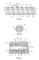
- FIG. 5 is a side cross section of the rock bolt embedded in situ.
- the drawings illustrate a self drilling rock bolt having features that improve the bolt's drilling, fixing, and anchoring, capabilities when drilled and cemented, or grouted, in a hole. It is understood that while the preferred embodiment as illustrated is a self drilling rock bolt, the invention equally applies to hollow rock bolts that are not self drilling, that is rock bolts that are inserted into a pre-drilled hole. It is also appreciated that the rock bolt may not be hollow all the way through, but may be solid along at least a portion of its length.
- the rock bolt 10 as illustrated in the drawings comprises a shaft 12 that has a spiral form protruding from an exterior surface 13 of the shaft wherein the spiral form has a flank angle ⁇ of between 30° and 60° relative to a normal axis N on (that is, perpendicular to) the surface 13 of the shaft 12 .
- the spiral form is described as a fixing thread 14 because one of the main functions of the spiral form is to fix, or anchor, the rock bolt 10 in a column of grout 16 ( FIG. 5 ) that has been poured into a drilled hole 18 , whether the drilled hole is created by the rock bolt itself in a self-drilling operation or by a separate drilling operation.
- the fixing thread 14 creates a mechanical lock between the rock bolt and rock strata 19 through the grout column 16 .
- Flank angle ⁇ is best seen in FIGS. 3 and 5 which closely illustrate the fixing thread 14 in profile where the flank walls 22 form an angle ⁇ with the normal axis N on the surface 13 of shaft 12 .
- Flank walls 22 form the ascending and descending walls of the crest 15 of the fixing thread 14 .
- a rock bolt having a fixing thread, or spiral form, with a flank angle in the range described has several advantages.
- the spiral form propels rock cuttings and shavings away from the drill tip and the flank angle assists in pushing the cuttings into the annulus of the hole surrounding the rock bolt assisting in keeping the debris moving and flushing out of the hole.
- the flank angle has the advantage of optimally transferring a load between the rack bolt and the rock strata minimising shearing stresses on the fixing thread when, in use, the bolt experiences axial tension.
- the forces transferred from a flank angle of between 30° and 60° and preferably 45° optimises and evenly distributes the compressive forces between the rock bolt and rock strata to minimise concentrated forces on the fixing thread. This in turn provides, through grout block 20 ( FIG. 5 ), increased cohesion between the rock bolt and grout and improves structural integrity and strength of the rock bolt installation.
- the rock bolt 10 in the preferred embodiment is formed by cold forming techniques as opposed to hot working the spiral form onto the exterior surface of the shaft. It is of course understood that while cold working techniques are preferred, hot rolling techniques may still be used.
- Cold working the hollow rock bolt would comprise beginning the process with a cold drawn seamless hollow tube, or shaft.
- a seamed tube is also possible.
- the cold drawn seamless would have the best strength and roundness tolerances.
- a seamed tube would be weaker, less accurate but cheaper.
- the hollow shaft is then fed, or passed, through a first assembly of thread rollers for cold forming the spiral formation (fixing thread 14 ) on the exterior surface 13 of shaft 12 .
- Other threads that may be incorporated on to the shaft, as discussed below, are cold formed by passing the shaft through further cold roller assemblies.
- the rock bolt 10 as illustrated in the drawings is typically 0.5 meters to 5.0 meters in length.
- the fixing thread 14 has a pitch P of at least 7 mm and a maximum pitch of 20 mm.
- the pitch of the thread is measured as the distance between the crests 15 or troughs 17 of the thread.
- the fixing thread having a pitch of at least 7 mm can assist in achieving a suitable mechanical lock between a rock bolt 10 and grout 16 .
- a preferred pitch is approximately 10 mm.
- the large pitch of the thread also acts as an auger during drilling, helping to remove the cuttings from the hole.
- the fixing thread 14 is provided as a continuous helical thread along a major portion of shaft 12 and, in this embodiment, along at least half the shaft's length.
- the debris clearing and fixing attributes of the rock bolt are provided along a substantial portion of the shaft.
- the fixing thread need not be continuous along the shaft's length but may instead be broken into segmented thread sections or as otherwise required depending on the additional functions required of the rock bolt
- the depth of the fixing thread may vary depending on the length of the rock bolt, its specific application in a particular rock strata, the grout type used, the wall thickness, and the diameter and material properties of the bolt itself.
- a suitable depth of fixing thread would be between 1-4 mm
- the fixing thread of the self drilling rock bolt is a right handed thread.
- An anchor attachment thread 24 is provided at a drilling end 28 of the shaft for receiving an anchoring device 25 which features in one preferred embodiment of the self drilling rock bolt and as illustrated in FIGS. 1 and 2 .
- the attachment thread 24 towards the drilling end 28 of the shaft is spaced from the fixing thread 14 by a gap 30 .
- Attachment thread 24 is a regular thread provided on rock bolts in that the thread has a pitch of approximately less than 5 mm, typically 2.5 to 3.0 mm.
- self drilling rock bolt 10 includes a mounting end 26 and a drilling end 28 .
- the mounting end 26 is provided with a mounting thread 27 in order to allow the rock bolt 10 to be mounted to a drilling apparatus (not shown) by way of a drive coupler 34 such that the drilling apparatus can impart rotation and thrust to the rock bolt 10 .
- the mounting thread 27 also has a pitch of less than 5 mm.
- attachment thread 24 and mounting thread 27 are also formed by cold working a cold drawn seamless hollow tube before or after the fixing thread is cold formed in separate cold working steps by passing the tube through roller assemblies and separately forming the attachment thread and mounting thread.
- attachment thread 24 is a left handed thread which allows the anchoring device 25 to be activated once the self drilling rock bolt has completed its drilling operation.
- the anchoring device 25 which is coupled to attachment thread 24 , is activated in the drilled hole to anchor the rock bolt 10 in position in the hole in preparation for grouting.
- attachment thread 24 is left handed which will allow the anchoring device to move with the drilling direction and remain inactivated.
- shaft 12 includes a hollow central passage longitudinally therethrough which is a flush channel 32 allowing fluid to be passed from the mounting end 26 of the shaft to the drilling end 28 for flushing drilled rock away from the drilling end during drilling.
- the drilling end 28 incorporates a drill bit 29 having a drill tip 31 .
- the drill bit 29 is provided with an external thread 33 at the opposite end of the drill tip 32 for connecting the drill bit to the rock bolt shaft 12 .
- the flush channel 32 is provided with an inner thread 35 which is complementary to the external thread 33 of the drill bit 29 so that the drill bit can be screwed on to the end of shaft 12 .
- the drill bit also contains an internal passage 36 that is in communication with flush channel 32 .
- the threaded coupling between the drill bit and shaft 12 is a right handed thread so that during a drilling operation, which typically induces right hand rotation of the shaft, the threaded coupling between the drill bit and shaft tightens.
- the rock bolt need not be a self drilling rock bolt.
- the rock bolt may have a partially solid shaft and may not necessarily be provided with any other threads other than the fixing thread 14 because the rock bolt may be manually inserted into a drilled hole.
- the present rock bolt having a fixing thread with a flank angle ⁇ of between 30° and 60° results in marked improvements in the cohesion of the rock bolt with grout in a grout column and improved strength to the bolt. This in turn improves the structural integrity of the support system used for retaining rock. Cold forming the rock bolt 10 further increases the bolt strength, and more specifically the bolt's yield strength.
Abstract
Description
Claims (19)
Applications Claiming Priority (3)
| Application Number | Priority Date | Filing Date | Title |
|---|---|---|---|
| AU2007214341A AU2007214341B8 (en) | 2007-08-31 | 2007-08-31 | Rock Bolt |
| AU2007214341 | 2007-08-31 | ||
| PCT/SE2008/000297 WO2009029012A1 (en) | 2007-08-31 | 2008-04-30 | Hollow rock bolt, self -drilling rock bolt and method of forming a hollow rock bolt |
Publications (2)
| Publication Number | Publication Date |
|---|---|
| US20100202838A1 US20100202838A1 (en) | 2010-08-12 |
| US8851802B2 true US8851802B2 (en) | 2014-10-07 |
Family
ID=40387543
Family Applications (1)
| Application Number | Title | Priority Date | Filing Date |
|---|---|---|---|
| US12/675,562 Expired - Fee Related US8851802B2 (en) | 2007-08-31 | 2008-04-30 | Rock bolt |
Country Status (7)
| Country | Link |
|---|---|
| US (1) | US8851802B2 (en) |
| CN (1) | CN101784753B (en) |
| AU (1) | AU2007214341B8 (en) |
| CA (1) | CA2695766A1 (en) |
| RU (1) | RU2458226C2 (en) |
| WO (1) | WO2009029012A1 (en) |
| ZA (1) | ZA201001438B (en) |
Cited By (1)
| Publication number | Priority date | Publication date | Assignee | Title |
|---|---|---|---|---|
| US9845678B2 (en) | 2015-05-08 | 2017-12-19 | Normet International Ltd. | Locally anchored self-drilling hollow rock bolt |
Families Citing this family (16)
| Publication number | Priority date | Publication date | Assignee | Title |
|---|---|---|---|---|
| AU2007214343B2 (en) * | 2007-08-31 | 2009-08-13 | Sandvik Intellectual Property Ab | Rock bolt with mechanical anchor |
| AU2007214341B8 (en) * | 2007-08-31 | 2015-02-19 | Sandvik Intellectual Property Ab | Rock Bolt |
| DE102010002214A1 (en) * | 2010-02-23 | 2011-08-25 | Hilti Aktiengesellschaft | Reinforcement and / or anchor bolt |
| AU2010206071B2 (en) * | 2010-07-30 | 2012-07-12 | Sandvik Intellectual Property Ab | A rock bolt and an anchoring device |
| US8888413B2 (en) * | 2010-11-09 | 2014-11-18 | Hubbell Incorporated | Transition coupling between cylindrical drive shaft and helical pile shaft |
| DE102010043769B4 (en) * | 2010-11-11 | 2015-07-09 | Hilti Aktiengesellschaft | Anchor assembly, especially for mining and tunneling |
| DE102010043765B4 (en) * | 2010-11-11 | 2014-08-28 | Hilti Aktiengesellschaft | Armature assembly and method of making an armature assembly |
| PT3019700T (en) * | 2013-07-12 | 2017-10-30 | Minova Int Ltd | Yieldable rock anchor |
| CN104675419A (en) * | 2013-12-02 | 2015-06-03 | 张弘 | Cylindrical pocket type anchor rod fixing structure |
| CL2014001002A1 (en) * | 2013-12-12 | 2014-11-28 | Ncm Innovations Pty Ltd | Rock anchor bolt including an elongated cylindrical body having, a first distal end and a second opposite proximal end, a threaded portion at the second end, a first anchor located at or at least partially located at a first end portion of the body, a second anchor, a first stem portion between the first and second anchor. |
| US9862040B2 (en) | 2014-09-30 | 2018-01-09 | Sandvik Intellectual Property Ab | Mechanism for enhanced, bi-directional fine adjustment of cutting insert cartridges in machine tools |
| US10941657B2 (en) * | 2016-07-12 | 2021-03-09 | Fci Holdings Delaware, Inc. | Corrosion resistant yieldable bolt |
| ZA201608232B (en) * | 2016-11-28 | 2019-01-30 | Orica Mining Services South Africa Pty Ltd | Self-drilling rock bolt with internal mixer |
| CA2957748C (en) | 2017-02-13 | 2018-05-01 | Lyle Kenneth Adams | Rock bolt seal |
| RU2018129117A (en) * | 2017-08-14 | 2020-02-10 | Рэттлджэк Инновейшнз Пти Лтд. | Safety plug |
| CN211038693U (en) * | 2019-10-31 | 2020-07-17 | 何满潮 | NPR anchor rod |
Citations (46)
| Publication number | Priority date | Publication date | Assignee | Title |
|---|---|---|---|---|
| US1379209A (en) * | 1919-06-21 | 1921-05-24 | John H Phillips | Anchor-drill bolt |
| US2171985A (en) * | 1938-07-28 | 1939-09-05 | Star Expansion Bolt Company | Bolt anchor |
| US3653217A (en) * | 1970-08-03 | 1972-04-04 | Chester I Williams | Rock bolt rod configuration |
| US3702060A (en) * | 1971-02-25 | 1972-11-07 | James Deans Cumming | Resin-bonded expansion shell |
| US3940941A (en) * | 1973-04-02 | 1976-03-02 | Acieries Reunies De Burbach-Eich-Dudelange S.A. Arbed | Anchor bolts for mine roofs and method for installing same |
| US4026186A (en) * | 1976-02-23 | 1977-05-31 | Illinois Tool Works Inc. | Self-drilling one-piece masonry anchor |
| US4318773A (en) * | 1977-05-14 | 1982-03-09 | Bayer Aktiengesellschaft | Process for the concentration of solutions with simultaneous setting |
| US4437795A (en) * | 1981-11-02 | 1984-03-20 | Birmingham Bolt Company | Mine roof anchor assembly |
| US4531861A (en) * | 1983-08-15 | 1985-07-30 | Kash Maurice D | Adhesively secured anchor rod |
| US4666345A (en) * | 1985-11-14 | 1987-05-19 | Seegmiller Ben L | Rock bolt structure |
| US4904123A (en) * | 1989-06-19 | 1990-02-27 | Jennmar Corporation | Expansion assembly for mine roof bolts utilized in small diameter bore holes |
| US4990042A (en) * | 1989-09-05 | 1991-02-05 | Szayer Geza J | Self-drilling blind setting rivet |
| US5183357A (en) * | 1990-02-05 | 1993-02-02 | Sfs Stadler Holding Ag | Rivet fastener with drilling bit |
| US5297909A (en) * | 1993-04-13 | 1994-03-29 | Tsay Leu Wen | Self-drilling expansion drill |
| US5437526A (en) * | 1991-12-21 | 1995-08-01 | Dyckerhoff & Witmann Aktiengesellschaft | Arrangement for anchoring a rod-shaped tension member of composite fiber material |
| US5664900A (en) * | 1992-05-28 | 1997-09-09 | Matthies; Klaus E. | Dowel joint system for connecting elements of a solid material |
| EP0794336A1 (en) | 1996-03-07 | 1997-09-10 | HILTI Aktiengesellschaft | Anchoring bar for compound anchor |
| US5794985A (en) * | 1995-03-23 | 1998-08-18 | Hydril Company | Threaded pipe connection |
| US6029417A (en) * | 1997-02-04 | 2000-02-29 | Hilti Aktiengesellschaft | Anchor rod for an attachment anchor |
| US6227782B1 (en) * | 1999-05-28 | 2001-05-08 | Stephen Bowling | Self-locking threaded fastener assembly |
| CN1317627A (en) | 2000-04-10 | 2001-10-17 | 希尔蒂股份公司 | Bolt tube with mould surface |
| RU2201506C2 (en) | 2000-12-13 | 2003-03-27 | Ануфриев Виктор Евгеньевич | Anchor |
| RU29748U1 (en) | 2002-07-09 | 2003-05-27 | Общество с ограниченной ответственностью "Горный инструмент" | Anchor rod |
| WO2003102374A1 (en) | 2002-05-30 | 2003-12-11 | Industrial Roll Formers Pty Limited | Threaded bar & rock bolts formed therefrom |
| US6829871B1 (en) * | 1998-12-01 | 2004-12-14 | Cobra Fixations Cie Ltee-Cobra Anchors Co., Ltd. | Wedge anchor for concrete |
| RU2280166C2 (en) | 2004-03-26 | 2006-07-20 | Виктор Евгеньевич Ануфриев | Anchoring bolt |
| US20060216190A1 (en) * | 2004-11-08 | 2006-09-28 | Beaven Robert W | Pump |
| US20060263171A1 (en) * | 2003-02-20 | 2006-11-23 | Manfred Schwarz | Self-tapping screw for use in low ductile materials |
| RU2292459C1 (en) | 2005-07-19 | 2007-01-27 | Общество С Ограниченной Ответственностью "Бийский Завод Стеклопластиков" | Mine lining anchor |
| US7217195B2 (en) * | 2003-08-12 | 2007-05-15 | Yugen Kaisha Art Screw | Method of producing left-right screw |
| WO2007053893A1 (en) | 2005-11-09 | 2007-05-18 | Sandvik Intellectual Property Ab | Self drilling rock bolt |
| WO2007059580A1 (en) | 2005-11-24 | 2007-05-31 | Peter Andrew Gray | Self drilling rock bolt |
| US20070217869A1 (en) * | 2003-10-29 | 2007-09-20 | Grinaker-Lta Limited | Rock bolt |
| US20070243026A1 (en) * | 2006-04-18 | 2007-10-18 | Mansour Mining Inc. | Detachable anchor bolt mixing head for use in mine roof support systems and method of using same |
| US20080008553A1 (en) * | 2006-07-10 | 2008-01-10 | Robert Andrew Gillis | Self-drilling anchor screw and method of using the same |
| US20080038068A1 (en) * | 2006-07-20 | 2008-02-14 | Jennmar Corporation | Rock bolt |
| WO2008060211A1 (en) | 2006-11-15 | 2008-05-22 | Sandvik Intellectual Property Ab | A rock bolt and an anchoring device |
| US20090041550A1 (en) * | 2007-08-07 | 2009-02-12 | Jennmar Corporation | Expansion bail anchor and method |
| US20090324343A1 (en) * | 2006-02-24 | 2009-12-31 | Minova International Limited | Injection bolt with a fixed static mixer |
| US20100003088A1 (en) * | 2006-12-19 | 2010-01-07 | Marek Grocholewski | Anchor with grout jacket |
| US20100202838A1 (en) * | 2007-08-31 | 2010-08-12 | Steven Weaver | Rock bolt |
| US20100278593A1 (en) * | 2001-01-12 | 2010-11-04 | Cook James D | Expansion shell assembly |
| US20100310323A1 (en) * | 2008-01-31 | 2010-12-09 | Fci Holdings Delaware, Inc. | Rock bolt assembly |
| US20110002745A1 (en) * | 2008-02-29 | 2011-01-06 | Atlas Copco Mai Gmbh | sliding anchor |
| US20110070034A1 (en) * | 2008-03-18 | 2011-03-24 | Frank Schmidt | Corrosion-protected, self-drilling anchor and anchor subunit and method for the production thereof |
| US20110206468A1 (en) * | 2010-02-23 | 2011-08-25 | Hilti Aktiengesellschaft | Reinforcement and/or anchor bolt |
Family Cites Families (6)
| Publication number | Priority date | Publication date | Assignee | Title |
|---|---|---|---|---|
| SU730967A1 (en) * | 1978-01-05 | 1980-04-30 | Всесоюзный научно-исследовательский институт золота и редких металлов | Anchor |
| CN2547875Y (en) * | 2001-06-15 | 2003-04-30 | 孔祥清 | Cold press head equal-strength anchoring bolt |
| CN2491604Y (en) * | 2001-07-24 | 2002-05-15 | 任绪民 | Support anchor arm |
| RU22971U1 (en) * | 2001-09-17 | 2002-05-10 | Закрытое акционерное общество "СибТрансУголь" | ANCHOR |
| CN1268832C (en) * | 2002-08-09 | 2006-08-09 | 孔祥清 | Spiral sharp-rib anchor rod and spiral rib drilling rod for drilling hole of spiral sharp-rib anchor rod |
| CN2663656Y (en) | 2003-12-22 | 2004-12-15 | 刘金庄 | Adhesive type recoverable plastic anchor stock |
-
2007
- 2007-08-31 AU AU2007214341A patent/AU2007214341B8/en not_active Ceased
-
2008
- 2008-04-30 RU RU2010112389/03A patent/RU2458226C2/en not_active IP Right Cessation
- 2008-04-30 CA CA2695766A patent/CA2695766A1/en not_active Abandoned
- 2008-04-30 WO PCT/SE2008/000297 patent/WO2009029012A1/en active Application Filing
- 2008-04-30 US US12/675,562 patent/US8851802B2/en not_active Expired - Fee Related
- 2008-04-30 CN CN2008801038865A patent/CN101784753B/en not_active Expired - Fee Related
-
2010
- 2010-02-26 ZA ZA2010/01438A patent/ZA201001438B/en unknown
Patent Citations (49)
| Publication number | Priority date | Publication date | Assignee | Title |
|---|---|---|---|---|
| US1379209A (en) * | 1919-06-21 | 1921-05-24 | John H Phillips | Anchor-drill bolt |
| US2171985A (en) * | 1938-07-28 | 1939-09-05 | Star Expansion Bolt Company | Bolt anchor |
| US3653217A (en) * | 1970-08-03 | 1972-04-04 | Chester I Williams | Rock bolt rod configuration |
| US3702060A (en) * | 1971-02-25 | 1972-11-07 | James Deans Cumming | Resin-bonded expansion shell |
| US3940941A (en) * | 1973-04-02 | 1976-03-02 | Acieries Reunies De Burbach-Eich-Dudelange S.A. Arbed | Anchor bolts for mine roofs and method for installing same |
| US4026186A (en) * | 1976-02-23 | 1977-05-31 | Illinois Tool Works Inc. | Self-drilling one-piece masonry anchor |
| US4318773A (en) * | 1977-05-14 | 1982-03-09 | Bayer Aktiengesellschaft | Process for the concentration of solutions with simultaneous setting |
| US4437795A (en) * | 1981-11-02 | 1984-03-20 | Birmingham Bolt Company | Mine roof anchor assembly |
| US4531861A (en) * | 1983-08-15 | 1985-07-30 | Kash Maurice D | Adhesively secured anchor rod |
| US4666345A (en) * | 1985-11-14 | 1987-05-19 | Seegmiller Ben L | Rock bolt structure |
| US4904123A (en) * | 1989-06-19 | 1990-02-27 | Jennmar Corporation | Expansion assembly for mine roof bolts utilized in small diameter bore holes |
| US4990042A (en) * | 1989-09-05 | 1991-02-05 | Szayer Geza J | Self-drilling blind setting rivet |
| US5183357A (en) * | 1990-02-05 | 1993-02-02 | Sfs Stadler Holding Ag | Rivet fastener with drilling bit |
| US5437526A (en) * | 1991-12-21 | 1995-08-01 | Dyckerhoff & Witmann Aktiengesellschaft | Arrangement for anchoring a rod-shaped tension member of composite fiber material |
| US5664900A (en) * | 1992-05-28 | 1997-09-09 | Matthies; Klaus E. | Dowel joint system for connecting elements of a solid material |
| US5297909A (en) * | 1993-04-13 | 1994-03-29 | Tsay Leu Wen | Self-drilling expansion drill |
| US5794985A (en) * | 1995-03-23 | 1998-08-18 | Hydril Company | Threaded pipe connection |
| EP0794336A1 (en) | 1996-03-07 | 1997-09-10 | HILTI Aktiengesellschaft | Anchoring bar for compound anchor |
| US6029417A (en) * | 1997-02-04 | 2000-02-29 | Hilti Aktiengesellschaft | Anchor rod for an attachment anchor |
| US6829871B1 (en) * | 1998-12-01 | 2004-12-14 | Cobra Fixations Cie Ltee-Cobra Anchors Co., Ltd. | Wedge anchor for concrete |
| US6227782B1 (en) * | 1999-05-28 | 2001-05-08 | Stephen Bowling | Self-locking threaded fastener assembly |
| CN1317627A (en) | 2000-04-10 | 2001-10-17 | 希尔蒂股份公司 | Bolt tube with mould surface |
| US20020046535A1 (en) * | 2000-04-10 | 2002-04-25 | Wolfgang Ludwig | Tubular anchor |
| RU2201506C2 (en) | 2000-12-13 | 2003-03-27 | Ануфриев Виктор Евгеньевич | Anchor |
| US20100278593A1 (en) * | 2001-01-12 | 2010-11-04 | Cook James D | Expansion shell assembly |
| WO2003102374A1 (en) | 2002-05-30 | 2003-12-11 | Industrial Roll Formers Pty Limited | Threaded bar & rock bolts formed therefrom |
| RU29748U1 (en) | 2002-07-09 | 2003-05-27 | Общество с ограниченной ответственностью "Горный инструмент" | Anchor rod |
| US20060263171A1 (en) * | 2003-02-20 | 2006-11-23 | Manfred Schwarz | Self-tapping screw for use in low ductile materials |
| US7217195B2 (en) * | 2003-08-12 | 2007-05-15 | Yugen Kaisha Art Screw | Method of producing left-right screw |
| US20070217869A1 (en) * | 2003-10-29 | 2007-09-20 | Grinaker-Lta Limited | Rock bolt |
| RU2280166C2 (en) | 2004-03-26 | 2006-07-20 | Виктор Евгеньевич Ануфриев | Anchoring bolt |
| US20060216190A1 (en) * | 2004-11-08 | 2006-09-28 | Beaven Robert W | Pump |
| RU2292459C1 (en) | 2005-07-19 | 2007-01-27 | Общество С Ограниченной Ответственностью "Бийский Завод Стеклопластиков" | Mine lining anchor |
| WO2007053893A1 (en) | 2005-11-09 | 2007-05-18 | Sandvik Intellectual Property Ab | Self drilling rock bolt |
| US20090220309A1 (en) * | 2005-11-09 | 2009-09-03 | Sandvik Intellectual Property Ab | Self Drilling Rock Bolt |
| WO2007059580A1 (en) | 2005-11-24 | 2007-05-31 | Peter Andrew Gray | Self drilling rock bolt |
| US20090324343A1 (en) * | 2006-02-24 | 2009-12-31 | Minova International Limited | Injection bolt with a fixed static mixer |
| US20070243026A1 (en) * | 2006-04-18 | 2007-10-18 | Mansour Mining Inc. | Detachable anchor bolt mixing head for use in mine roof support systems and method of using same |
| US20080008553A1 (en) * | 2006-07-10 | 2008-01-10 | Robert Andrew Gillis | Self-drilling anchor screw and method of using the same |
| US20080038068A1 (en) * | 2006-07-20 | 2008-02-14 | Jennmar Corporation | Rock bolt |
| US20100098500A1 (en) | 2006-11-15 | 2010-04-22 | Sandvik Intellectual Property Ab | Drilling tool, a self-drilling rock bolt, a drill bit, an anchoring device for a self-drilling rock bolt, a shaft for a drilling tool and an end coupling for a drilling tool |
| WO2008060211A1 (en) | 2006-11-15 | 2008-05-22 | Sandvik Intellectual Property Ab | A rock bolt and an anchoring device |
| US20100003088A1 (en) * | 2006-12-19 | 2010-01-07 | Marek Grocholewski | Anchor with grout jacket |
| US20090041550A1 (en) * | 2007-08-07 | 2009-02-12 | Jennmar Corporation | Expansion bail anchor and method |
| US20100202838A1 (en) * | 2007-08-31 | 2010-08-12 | Steven Weaver | Rock bolt |
| US20100310323A1 (en) * | 2008-01-31 | 2010-12-09 | Fci Holdings Delaware, Inc. | Rock bolt assembly |
| US20110002745A1 (en) * | 2008-02-29 | 2011-01-06 | Atlas Copco Mai Gmbh | sliding anchor |
| US20110070034A1 (en) * | 2008-03-18 | 2011-03-24 | Frank Schmidt | Corrosion-protected, self-drilling anchor and anchor subunit and method for the production thereof |
| US20110206468A1 (en) * | 2010-02-23 | 2011-08-25 | Hilti Aktiengesellschaft | Reinforcement and/or anchor bolt |
Non-Patent Citations (2)
| Title |
|---|
| Notification of the First Office Action against Chinese Application No. 200880103886.5, dated Sep. 23, 2011. |
| Official Action against Russian Application No. 2010112389/03(017338), dated Dec. 22, 2011. |
Cited By (1)
| Publication number | Priority date | Publication date | Assignee | Title |
|---|---|---|---|---|
| US9845678B2 (en) | 2015-05-08 | 2017-12-19 | Normet International Ltd. | Locally anchored self-drilling hollow rock bolt |
Also Published As
| Publication number | Publication date |
|---|---|
| CA2695766A1 (en) | 2009-03-05 |
| US20100202838A1 (en) | 2010-08-12 |
| WO2009029012A1 (en) | 2009-03-05 |
| CN101784753A (en) | 2010-07-21 |
| CN101784753B (en) | 2013-10-16 |
| RU2458226C2 (en) | 2012-08-10 |
| RU2010112389A (en) | 2011-10-20 |
| ZA201001438B (en) | 2013-08-28 |
| AU2007214341B2 (en) | 2015-01-15 |
| AU2007214341A1 (en) | 2009-03-19 |
| AU2007214341A8 (en) | 2015-02-19 |
| AU2007214341B8 (en) | 2015-02-19 |
Similar Documents
| Publication | Publication Date | Title |
|---|---|---|
| US8851802B2 (en) | Rock bolt | |
| CN107820533B (en) | Self-drilling hollow rock anchor rod with local anchoring | |
| US9091167B2 (en) | Self drilling rock bolt | |
| US5433558A (en) | Self-tapping, and self-tapping and self-drilling, rock bolts | |
| US20070269274A1 (en) | Rock Bolt | |
| US20110206468A1 (en) | Reinforcement and/or anchor bolt | |
| AU2021105904A4 (en) | Self-drilling rock bolt | |
| CN108843357B (en) | Double-layer rock anchor rod and construction method | |
| CN111305887B (en) | Shear-resistant anchor pipe cable supporting structure and construction method | |
| RU2148697C1 (en) | Wedge-type whipstock | |
| AU2021106794A4 (en) | Rock bolt anchor | |
| AU2021218166A1 (en) | Rock bolt | |
| AT412361B (en) | METHOD AND DEVICE FOR SAVING THE MOUNTAIN AND REMOVING STOOLS, TUNNELS & DIG. | |
| AU652765B2 (en) | Drillable ground support bolt | |
| AU2004243343B2 (en) | Rockbolt | |
| RU2134351C1 (en) | Spiral anchor | |
| AU666105B2 (en) | Self-tapping, and self-tapping and self-drilling, rock bolts | |
| AU2014203600A1 (en) | Rock bolt assembly | |
| WO2010006374A1 (en) | Stabilising rock masses | |
| AU1015002A (en) | Rock bolt with keying deformations |
Legal Events
| Date | Code | Title | Description |
|---|---|---|---|
| AS | Assignment |
Owner name: SANDVIK INTELLECTUAL PROPERTY AB, SWEDEN Free format text: ASSIGNMENT OF ASSIGNORS INTEREST;ASSIGNORS:WEAVER, STEVEN;HORSCH, JOHN;REEL/FRAME:024211/0262 Effective date: 20100208 |
|
| FEPP | Fee payment procedure |
Free format text: MAINTENANCE FEE REMINDER MAILED (ORIGINAL EVENT CODE: REM.) |
|
| LAPS | Lapse for failure to pay maintenance fees |
Free format text: PATENT EXPIRED FOR FAILURE TO PAY MAINTENANCE FEES (ORIGINAL EVENT CODE: EXP.); ENTITY STATUS OF PATENT OWNER: LARGE ENTITY |
|
| STCH | Information on status: patent discontinuation |
Free format text: PATENT EXPIRED DUE TO NONPAYMENT OF MAINTENANCE FEES UNDER 37 CFR 1.362 |
|
| FP | Lapsed due to failure to pay maintenance fee |
Effective date: 20181007 |