US8852201B2 - Microfracture instrument - Google Patents
Microfracture instrument Download PDFInfo
- Publication number
- US8852201B2 US8852201B2 US12/731,971 US73197110A US8852201B2 US 8852201 B2 US8852201 B2 US 8852201B2 US 73197110 A US73197110 A US 73197110A US 8852201 B2 US8852201 B2 US 8852201B2
- Authority
- US
- United States
- Prior art keywords
- sheath
- drill
- bone
- drill tip
- shaft
- Prior art date
- Legal status (The legal status is an assumption and is not a legal conclusion. Google has not performed a legal analysis and makes no representation as to the accuracy of the status listed.)
- Active, expires
Links
Images


Classifications
-
- A—HUMAN NECESSITIES
- A61—MEDICAL OR VETERINARY SCIENCE; HYGIENE
- A61B—DIAGNOSIS; SURGERY; IDENTIFICATION
- A61B17/00—Surgical instruments, devices or methods, e.g. tourniquets
- A61B17/16—Bone cutting, breaking or removal means other than saws, e.g. Osteoclasts; Drills or chisels for bones; Trepans
- A61B17/1613—Component parts
- A61B17/1633—Sleeves, i.e. non-rotating parts surrounding the bit shaft, e.g. the sleeve forming a single unit with the bit shaft
-
- A—HUMAN NECESSITIES
- A61—MEDICAL OR VETERINARY SCIENCE; HYGIENE
- A61B—DIAGNOSIS; SURGERY; IDENTIFICATION
- A61B17/00—Surgical instruments, devices or methods, e.g. tourniquets
- A61B17/16—Bone cutting, breaking or removal means other than saws, e.g. Osteoclasts; Drills or chisels for bones; Trepans
- A61B17/1604—Chisels; Rongeurs; Punches; Stamps
-
- A—HUMAN NECESSITIES
- A61—MEDICAL OR VETERINARY SCIENCE; HYGIENE
- A61B—DIAGNOSIS; SURGERY; IDENTIFICATION
- A61B17/00—Surgical instruments, devices or methods, e.g. tourniquets
- A61B17/16—Bone cutting, breaking or removal means other than saws, e.g. Osteoclasts; Drills or chisels for bones; Trepans
- A61B17/1662—Bone cutting, breaking or removal means other than saws, e.g. Osteoclasts; Drills or chisels for bones; Trepans for particular parts of the body
- A61B17/1675—Bone cutting, breaking or removal means other than saws, e.g. Osteoclasts; Drills or chisels for bones; Trepans for particular parts of the body for the knee
-
- A—HUMAN NECESSITIES
- A61—MEDICAL OR VETERINARY SCIENCE; HYGIENE
- A61B—DIAGNOSIS; SURGERY; IDENTIFICATION
- A61B17/00—Surgical instruments, devices or methods, e.g. tourniquets
- A61B17/16—Bone cutting, breaking or removal means other than saws, e.g. Osteoclasts; Drills or chisels for bones; Trepans
- A61B17/1613—Component parts
- A61B17/1631—Special drive shafts, e.g. flexible shafts
-
- A—HUMAN NECESSITIES
- A61—MEDICAL OR VETERINARY SCIENCE; HYGIENE
- A61B—DIAGNOSIS; SURGERY; IDENTIFICATION
- A61B17/00—Surgical instruments, devices or methods, e.g. tourniquets
- A61B17/16—Bone cutting, breaking or removal means other than saws, e.g. Osteoclasts; Drills or chisels for bones; Trepans
- A61B17/1642—Bone cutting, breaking or removal means other than saws, e.g. Osteoclasts; Drills or chisels for bones; Trepans for producing a curved bore
-
- A—HUMAN NECESSITIES
- A61—MEDICAL OR VETERINARY SCIENCE; HYGIENE
- A61B—DIAGNOSIS; SURGERY; IDENTIFICATION
- A61B17/00—Surgical instruments, devices or methods, e.g. tourniquets
- A61B17/32—Surgical cutting instruments
- A61B17/320016—Endoscopic cutting instruments, e.g. arthroscopes, resectoscopes
- A61B17/32002—Endoscopic cutting instruments, e.g. arthroscopes, resectoscopes with continuously rotating, oscillating or reciprocating cutting instruments
- A61B2017/320032—Details of the rotating or oscillating shaft, e.g. using a flexible shaft
Definitions
- the present invention is directed to surgical instruments and, more particularly, to a device for treating chondral defects of the knee.
- articular cartilage defects Treatment of articular cartilage defects is typically accomplished by the microfracture procedure. This procedure is performed arthroscopically. Although articular cartilage defects may occur in any joint, the microfracture procedure is typically performed in the knee or shoulder. The surgeon visually assesses the defect and performs the procedure using special instruments that are inserted through small incisions around the joint. Unstable and loose cartilage is removed from the exposed bone so that there is a stable edge of cartilage surrounding the defect. Multiple holes (also called microfractures) are then made in the exposed bone about 3 to 4 mm apart. Bone marrow cells and blood from the holes combine to form a “super clot” that completely covers the damaged area. This marrow-rich clot is the basis for the new tissue formation. The microfracture technique produces a rough bone surface to which the clot adheres more easily. This clot eventually matures into firm repair tissue that becomes smooth and durable.
- the instruments currently used to make the microfractures are manual instruments such as curved picks and/or nitinol wires and guides.
- One powered option is a subchondral drill which is a straight drill covered by an outer sheath. The outer sheath covers the drill tip until it contacts bone and then the drill tip advances axially into the bone.
- the manual instruments are undesirable in that they typically require two hands to use since a mallet is used to drive the instruments into the bone.
- the impact loading of the mallet may cause the pick to slide or gouge the target site rather than puncture the site perpendicular to the axis of the trocar tip.
- the straight drill power instrument does not provide adequate accessibility or visibility to the site which is typically in a joint space.
- An instrument that can form the microfractures quickly and at pre-determined angles with repeatability is needed. Also needed is an instrument that allows the surgeon to quickly place the microfractures in the desired position using only one instrument attached to power, and with improved accessibility and visibility to the site.
- the present invention provides an instrument for forming microfractures quickly and at pre-determined angles.
- the instrument takes less time and replaces the use of multiple manual instruments.
- the instrument attaches to a power system such as that used for shavers and burrs to quickly drill small diameter holes at pre-determined angles into bone.
- the instrument is provided with a flexible trocar tip and a curved outer sheath.
- the shaft of the flexible trocar tip connects to the hand piece.
- the outer sheath protects the sharp trocar tip during insertion and is retracted once positioned to expose the sharp trocar tip.
- the instrument allows the surgeon to quickly place the microfractures in the desired position using only one instrument attached to power.
- FIG. 1 illustrates a side view of a microfracture instrument of the present invention with the trocar tip exposed;
- FIG. 1( a ) illustrates an enlarged view of the trocar tip of the microfracture instrument of FIG. 1 ;
- FIG. 2 illustrates a side view of the outer assembly of the microfracture instrument of FIG. 1 ;
- FIG. 3 illustrates a side view of the inner assembly of the microfracture instrument of FIG. 1 attached to the inner hub;
- FIG. 4 illustrates a side view of the inner assembly of FIG. 3 (without the inner hub);
- FIG. 5 illustrates a side view of the flex coil of the inner assembly of FIG. 3 ;
- FIG. 5( a ) illustrates an end view of the flex coil of the inner assembly of FIG. 5 ;
- FIG. 6 illustrates a side view of the drive tube of the inner assembly of FIG. 3 ;
- FIG. 6( a ) illustrates an end view of the drive tube of the inner assembly of FIG. 6 ;
- FIG. 7 illustrates a side view of the outer sheath of the outer assembly of FIG. 2 ;
- FIG. 7( a ) illustrates an end view of the outer sheath of the outer assembly of FIG. 7 ;
- FIG. 8 illustrates a side view of the trocar tip of the inner assembly of FIG. 3 ;
- FIG. 8( a ) illustrates a side view of the trocar tip of FIG. 8 , but rotated for about 90 degrees;
- FIG. 9 illustrates a transparent side view of the microfracture instrument of FIG. 1 ;
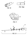
- FIGS. 10 and 10( a ) illustrate different views of the outer hub of the microfracture instrument of FIG. 1 ;
- FIG. 11 illustrates a side view of the molded cap of the microfracture instrument of FIG. 1 ;
- FIG. 12 illustrates a side view of various parts of the microfracture instrument of FIG. 1 ;
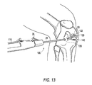
- FIG. 13 illustrates a method of using the microfracture instrument of FIG. 1 .
- the present invention provides a microfracture instrument for forming small diameter holes in bone.
- the microfracture instrument of the present invention is designed to attach to a power system (such as one used for shavers and burrs, for example) to quickly drill small diameter holes at pre-determined angles into bone.
- the microfracture instrument is provided with a flexible trocar tip and a curved outer sheath.
- the shaft of the flexible trocar tip connects to the hand piece.
- the outer sheath protects the sharp trocar tip during insertion and is retracted once positioned to expose the sharp trocar tip.
- the instrument allows the surgeon to quickly place the microfractures at the desired position using only one instrument attached to power.
- the present invention also provides a method of drilling a hole in a bone by inter alia: providing a shaft with a flexible end, the flexible end being coupled to a drill tip; providing a cannulated sheath with a distal end and a proximal end, the distal end of the sheath being curved and housing the drill tip; and retracting the sheath to cause the drill tip to extend beyond the distal end of the sheath.
- FIGS. 1-12 illustrate an exemplary microfracture instrument 100 of the present invention for forming small diameter holes in bone.
- the microfracture instrument 100 of the present invention may be employed during a microfracture procedure, which is conducted arthroscopically to treat articular cartilage defects, for example, chondral defects of the knee.
- the surgeon visually assesses the defect and performs the procedure using special instruments that are inserted through small incisions on the knee. After assessing the cartilage damage, any unstable or loose cartilage is removed from the exposed bone, leaving a stable edge of cartilage around the defect.
- microfractures Multiple holes (or microfractures) are then made in the exposed bone about 3 to 4 mm apart. Bone marrow cells and blood from the holes combine to form a “super clot” that completely covers the damaged area. This marrow-rich clot is the basis for the new tissue formation.
- the microfracture technique produces a rough bone surface that the clot adheres to more easily. This clot eventually matures into firm repair tissue that becomes smooth and durable. Similar microfracture procedures are used in other surgical sites to treat similar bone and cartilage defects, such as Hill-Sachs lesions in the shoulder.
- microfracture instrument 100 of the present invention includes an outer assembly 20 and an inner assembly 50 .
- the microfracture instrument 100 connects to a shaver hand piece (not shown) for power.
- the outer assembly 20 includes an outer sheath 29 having a cannulated shaft provided with a distal 25 and proximal end 27 .
- the distal end 25 of the sheath 29 is curved ( FIG. 1 ).
- the angle of curvature may be between about 5 to about 80 degrees, preferably between about 30 to about 60 degrees.
- the outer assembly 20 also includes an outer hub 21 with a retaining ring 25 .
- the outer hub 21 is designed to receive the inner assembly 50 through a most proximal opening 28 ( FIG. 9 ).
- the outer hub 21 is also provided with an actuator mechanism 35 ( FIG. 9 ) for moving the sheath 29 along a longitudinal axis of the microfracture instrument 100 .
- the proximal end 27 of the sheath 29 connects to the actuator mechanism 35 .
- the actuator mechanism 35 is a lever, but one skilled in the art will recognize alternate embodiments such as a button or a ratchet for moving the shaft along the longitudinal axis.
- the outer assembly 20 is further illustrated in more detail in FIG. 12 .
- the outer assembly 20 includes the outer sheath 29 , the actuator 35 , the spring 56 , the outer hub 21 , and a cap 90 .
- the cap 90 is shown in greater detail in FIG. 11 .
- inner assembly 50 of the microfracture instrument 100 is illustrated in more detail in FIGS. 3-6 and 8 .
- inner assembly 50 comprises an inner shaft 70 extending from a proximal end 77 to a distal end 75 .
- the distal end 75 of the inner shaft houses a drill tip or trocar tip 60 for creating small diameter holes in bone. Details of trocar tip 60 are illustrated in FIG. 8 , although the drill tip could have other geometries and could be fluted or in the form of a bur, for example.
- the inner assembly 50 further includes an inner hub 53 , a thrust washer 54 , a spring 56 , and a corresponding spring retainer 57 .
- the proximal end 77 of the inner shaft 70 connects to the inner hub 53 ( FIG. 3 ).
- inner hub 53 connects to a shaver hand piece for power to drive the trocar tip 60 into bone.
- the inner shaft 70 has a flexible portion 55 (a flex coil 55 shown in FIG. 5 ) allowing the inner assembly 50 to conform to the curvature of the distal end 25 of the outer sheath 29 of the outer assembly 20 .
- the outer sheath 29 of the microfracture instrument 100 When inserted into the joint space, the outer sheath 29 of the microfracture instrument 100 covers the trocar tip 60 protecting the surrounding anatomy. Once the desired location for creating the microfracture is located through the scope, the surgeon can manipulate the lever/actuator 35 to retract the sheath 29 thereby exposing the trocar tip 60 . Once the tip 60 is exposed, the surgeon may turn on the power to create the hole in the bone. This technique provides the surgeon with more accessibility to the bone in the joint space due to the curvature of the outer sheath. The profile of the instrument 100 is also reduced since the tip is retracted during insertion resulting in better placement of the instrument in the joint space. An additional safety feature is the protection of the surrounding anatomy from an exposed tip during insertion of the instrument prior to drilling.
- the damaged articular cartilage area is prepared in the standard fashion.
- the instrument 100 is then attached to a handpiece 110 with the trocar tip 60 retracted safely within the outer sheath 29 .
- the instrument 100 is passed into the joint space 140 through a cannula or percutaneously 130 .
- the actuator mechanism 35 is then actuated to laterally move outer sheath 29 , thereby exposing the trocar tip 60 so that the trocar tip 60 extends out of the outer sheath 29 .
- the trocar tip 60 is placed in the appropriate location for forming a hole 122 .
- the handpiece 110 is energized to rotate the trocar tip 60 and the trocar tip 60 is pushed into bone 120 until the outer sheath 29 contacts bone 120 , thereby forming a 1.5 mm hole 122 approximately 3 mm deep in the bone 120 .
- the instrument 100 is retracted while the handpiece 110 is still energized and the trocar tip 60 is rotating.
- the trocar tip 60 is retracted by raising the actuator 35 so that the trocar tip 60 is housed in outer sheath 29 and the instrument 100 is removed from the joint space.
- the instrument 100 is also an ideal tool for marking the femoral tunnel location in ACL reconstructive procedures by following the above steps and using the trocar tip 60 to mark a tunnel location within the femoral notch.
- the approximate tunnel location can be determined through the medial portal by placing the end of the sheath 29 at the over-top-position.
- the trailing edge of the laser mark 12 which is the edge of the mark 12 farthest from the end of the sheath 29 from which the trocar tip 60 extends, is used to reference the center of the tunnel in a Single Bundle ACL technique.
- the leading edge of the laser mark 12 which is the edge of the mark 12 nearest to the end of the sheath 29 from which the trocar tip 60 extends, is used to reference the center of the posterior tunnel in a Double Bundle ACL technique. After marking its position, the same measurement method is used to reference the center of the anterior tunnel referenced from the previously marked posterior tunnel position. Further, the leading and trailing edges of the laser mark 12 may be used to measure osteochondral defects.
- the laser mark 12 is 2 mm wide, the leading edge is 5 mm from the end of the sheath 29 from which the trocar tip 60 extends and the trailing edge is 7 mm from the end of the sheath 29 from which the trocar tip 60 extends. In other embodiments, different widths and distances may be used.
Abstract
Description
Claims (18)
Priority Applications (1)
| Application Number | Priority Date | Filing Date | Title |
|---|---|---|---|
| US12/731,971 US8852201B2 (en) | 2009-03-30 | 2010-03-25 | Microfracture instrument |
Applications Claiming Priority (2)
| Application Number | Priority Date | Filing Date | Title |
|---|---|---|---|
| US16473209P | 2009-03-30 | 2009-03-30 | |
| US12/731,971 US8852201B2 (en) | 2009-03-30 | 2010-03-25 | Microfracture instrument |
Publications (2)
| Publication Number | Publication Date |
|---|---|
| US20100249786A1 US20100249786A1 (en) | 2010-09-30 |
| US8852201B2 true US8852201B2 (en) | 2014-10-07 |
Family
ID=42212224
Family Applications (1)
| Application Number | Title | Priority Date | Filing Date |
|---|---|---|---|
| US12/731,971 Active 2031-03-28 US8852201B2 (en) | 2009-03-30 | 2010-03-25 | Microfracture instrument |
Country Status (2)
| Country | Link |
|---|---|
| US (1) | US8852201B2 (en) |
| EP (1) | EP2236100B1 (en) |
Cited By (29)
| Publication number | Priority date | Publication date | Assignee | Title |
|---|---|---|---|---|
| US8926615B2 (en) | 2002-12-03 | 2015-01-06 | Arthrosurface, Inc. | System and method for retrograde procedure |
| US8961614B2 (en) | 2004-11-22 | 2015-02-24 | Arthrosurface, Inc. | Articular surface implant and delivery system |
| US9044343B2 (en) | 2002-12-03 | 2015-06-02 | Arthrosurface Incorporated | System for articular surface replacement |
| US9055955B2 (en) | 2000-05-01 | 2015-06-16 | Arthrosurface Inc. | Bone resurfacing system and method |
| US9066716B2 (en) | 2011-03-30 | 2015-06-30 | Arthrosurface Incorporated | Suture coil and suture sheath for tissue repair |
| US9204873B2 (en) | 2000-05-01 | 2015-12-08 | Arthrosurface Incorporated | System and method for joint resurface repair |
| US9283076B2 (en) | 2009-04-17 | 2016-03-15 | Arthrosurface Incorporated | Glenoid resurfacing system and method |
| US9351745B2 (en) | 2003-02-24 | 2016-05-31 | Arthrosurface Incorporated | Trochlear resurfacing system and method |
| US9358029B2 (en) | 2006-12-11 | 2016-06-07 | Arthrosurface Incorporated | Retrograde resection apparatus and method |
| US9357989B2 (en) | 2000-05-01 | 2016-06-07 | Arthrosurface Incorporated | System and method for joint resurface repair |
| US9468448B2 (en) | 2012-07-03 | 2016-10-18 | Arthrosurface Incorporated | System and method for joint resurfacing and repair |
| US20160310194A1 (en) * | 2015-04-21 | 2016-10-27 | Arthrex, Inc. | Surgical assembly and method for repairing depression fractures |
| US9492200B2 (en) | 2013-04-16 | 2016-11-15 | Arthrosurface Incorporated | Suture system and method |
| US9510840B2 (en) * | 2012-03-09 | 2016-12-06 | Arthrosurface, Inc. | Microfracture apparatuses and methods |
| US9662126B2 (en) | 2009-04-17 | 2017-05-30 | Arthrosurface Incorporated | Glenoid resurfacing system and method |
| US9861492B2 (en) | 2014-03-07 | 2018-01-09 | Arthrosurface Incorporated | Anchor for an implant assembly |
| US10172626B2 (en) | 2008-04-15 | 2019-01-08 | The Lonnie and Shannon Paulos Trust | Tissue microfracture apparatus and methods of use |
| US10238401B2 (en) | 2013-09-23 | 2019-03-26 | Arthrosurface, Inc. | Microfracture apparatuses and methods |
| US10624748B2 (en) | 2014-03-07 | 2020-04-21 | Arthrosurface Incorporated | System and method for repairing articular surfaces |
| US10624752B2 (en) | 2006-07-17 | 2020-04-21 | Arthrosurface Incorporated | Tibial resurfacing system and method |
| US10695073B2 (en) | 2017-08-22 | 2020-06-30 | Arthrex, Inc. | Control system for retrograde drill medical device |
| US10702395B2 (en) | 2014-10-01 | 2020-07-07 | Arthrosurface, Inc. | Microfracture apparatuses and methods |
| US10792403B2 (en) | 2015-01-08 | 2020-10-06 | Arthrex, Inc. | Suction swab for surgical use |
| US10945743B2 (en) | 2009-04-17 | 2021-03-16 | Arthrosurface Incorporated | Glenoid repair system and methods of use thereof |
| US11160663B2 (en) | 2017-08-04 | 2021-11-02 | Arthrosurface Incorporated | Multicomponent articular surface implant |
| US11478358B2 (en) | 2019-03-12 | 2022-10-25 | Arthrosurface Incorporated | Humeral and glenoid articular surface implant systems and methods |
| US11607319B2 (en) | 2014-03-07 | 2023-03-21 | Arthrosurface Incorporated | System and method for repairing articular surfaces |
| US11712276B2 (en) | 2011-12-22 | 2023-08-01 | Arthrosurface Incorporated | System and method for bone fixation |
| EP4048171A4 (en) * | 2005-09-09 | 2023-11-22 | Warsaw Orthopedic, Inc. | Medical access device |
Families Citing this family (34)
| Publication number | Priority date | Publication date | Assignee | Title |
|---|---|---|---|---|
| US8801725B2 (en) | 2008-03-10 | 2014-08-12 | Zimmer Orthobiologics, Inc. | Instruments and methods used when repairing a defect on a tissue surface |
| US8911474B2 (en) * | 2009-07-16 | 2014-12-16 | Howmedica Osteonics Corp. | Suture anchor implantation instrumentation system |
| CA2812775C (en) | 2009-08-20 | 2015-09-29 | Howmedica Osteonics Corp. | Flexible acl instrumentation, kit and method |
| US9113916B2 (en) | 2010-08-31 | 2015-08-25 | Zimmer, Inc. | Drill bit for osteochondral drilling with guiding element and uses thereof |
| US8435305B2 (en) | 2010-08-31 | 2013-05-07 | Zimmer, Inc. | Osteochondral graft delivery device and uses thereof |
| WO2012103459A1 (en) | 2011-01-27 | 2012-08-02 | Smith & Nephew, Inc. | Stabilizing microfracture device |
| US9795398B2 (en) | 2011-04-13 | 2017-10-24 | Howmedica Osteonics Corp. | Flexible ACL instrumentation, kit and method |
| US8721648B2 (en) * | 2011-05-13 | 2014-05-13 | Biomet Manufacturing, Llc | Microfracture pick for femoral head |
| US9445803B2 (en) | 2011-11-23 | 2016-09-20 | Howmedica Osteonics Corp. | Filamentary suture anchor |
| US9155555B2 (en) * | 2012-01-31 | 2015-10-13 | Medtronic Xomed, Inc. | Surgical instrument with distal bearing assembly |
| US10194922B2 (en) | 2012-05-11 | 2019-02-05 | Peter L. Bono | Rotary oscillating bone, cartilage, and disk removal tool assembly |
| US11135026B2 (en) | 2012-05-11 | 2021-10-05 | Peter L. Bono | Robotic surgical system |
| US10835263B2 (en) | 2016-11-17 | 2020-11-17 | Peter L. Bono | Rotary oscillating surgical tool |
| US9232958B2 (en) | 2012-05-16 | 2016-01-12 | Smith & Nephew, Inc. | Reusable blade hub assembly |
| US8821494B2 (en) | 2012-08-03 | 2014-09-02 | Howmedica Osteonics Corp. | Surgical instruments and methods of use |
| US9078740B2 (en) | 2013-01-21 | 2015-07-14 | Howmedica Osteonics Corp. | Instrumentation and method for positioning and securing a graft |
| US9237894B2 (en) | 2013-01-31 | 2016-01-19 | Depuy Mitek, Llc | Methods and devices for forming holes in bone to stimulate bone growth |
| US9402620B2 (en) | 2013-03-04 | 2016-08-02 | Howmedica Osteonics Corp. | Knotless filamentary fixation devices, assemblies and systems and methods of assembly and use |
| US9788826B2 (en) | 2013-03-11 | 2017-10-17 | Howmedica Osteonics Corp. | Filamentary fixation device and assembly and method of assembly, manufacture and use |
| US9463013B2 (en) | 2013-03-13 | 2016-10-11 | Stryker Corporation | Adjustable continuous filament structure and method of manufacture and use |
| WO2014176270A1 (en) | 2013-04-22 | 2014-10-30 | Pivot Medical, Inc. | Method and apparatus for attaching tissue to bone |
| US10610211B2 (en) | 2013-12-12 | 2020-04-07 | Howmedica Osteonics Corp. | Filament engagement system and methods of use |
| US9833255B2 (en) * | 2013-12-26 | 2017-12-05 | Tenjin, Llc | Percussive surgical devices, systems, and methods of use thereof |
| US9808264B2 (en) | 2014-05-21 | 2017-11-07 | The Uab Research Foundation | Hinged microfracture awls |
| US9986992B2 (en) | 2014-10-28 | 2018-06-05 | Stryker Corporation | Suture anchor and associated methods of use |
| US10568616B2 (en) | 2014-12-17 | 2020-02-25 | Howmedica Osteonics Corp. | Instruments and methods of soft tissue fixation |
| US20160317162A1 (en) * | 2015-04-29 | 2016-11-03 | Tenjin LLC | Methods and systems for ligament repair |
| US10653431B2 (en) * | 2016-06-14 | 2020-05-19 | Medos International Sarl | Drill assemblies and methods for drilling into bone |
| EP3515332B1 (en) * | 2016-09-26 | 2022-08-03 | KLSMC Instruments, LLC | Arthroscopic drill |
| AU2018355215A1 (en) | 2017-10-23 | 2020-06-11 | Capstone Surgical Technologies, Llc | Rotary oscillating and linearly reciprocating surgical tool |
| CN111970984A (en) | 2018-01-12 | 2020-11-20 | 彼得·L·波纳 | Robot operation control system |
| USD902405S1 (en) | 2018-02-22 | 2020-11-17 | Stryker Corporation | Self-punching bone anchor inserter |
| EP3876860A1 (en) | 2018-11-06 | 2021-09-15 | Bono, Peter L. | Robotic surgical system and method |
| US11517328B2 (en) * | 2019-03-19 | 2022-12-06 | Arthrex, Inc. | Force absorption system for disposable shavers and burrs |
Citations (21)
| Publication number | Priority date | Publication date | Assignee | Title |
|---|---|---|---|---|
| US4541423A (en) * | 1983-01-17 | 1985-09-17 | Barber Forest C | Drilling a curved hole |
| US5439005A (en) * | 1993-03-02 | 1995-08-08 | Midas Rex Pneumatic Tools, Inc. | Surgical instrument with telescoping sleeve |
| US5667509A (en) * | 1995-03-02 | 1997-09-16 | Westin; Craig D. | Retractable shield apparatus and method for a bone drill |
| US5851208A (en) | 1996-10-15 | 1998-12-22 | Linvatec Corporation | Rotatable surgical burr |
| US6068642A (en) * | 1996-03-01 | 2000-05-30 | Orthopaedic Innovations, Inc. | Flexible cutting tool and methods for its use |
| US6312438B1 (en) * | 2000-02-01 | 2001-11-06 | Medtronic Xomed, Inc. | Rotary bur instruments having bur tips with aspiration passages |
| US20050054972A1 (en) * | 2003-09-09 | 2005-03-10 | Adams Kenneth M. | Surgical micro-burring instrument and method of performing sinus surgery |
| FR2861575A1 (en) | 2003-10-31 | 2005-05-06 | Medtronic Inc | Surgical dissection instrument for use in surgical system to dissect e.g. tissue of human patient, has fixation tube movably coupled to coupling assembly to form telescopic assembly for fixing tool at angle with respect to motor |
| US20050177168A1 (en) | 2004-02-11 | 2005-08-11 | Medtronic, Inc. | High speed surgical cutting instrument |
| US20050203527A1 (en) | 2004-03-03 | 2005-09-15 | Scimed Life Systems, Inc. | Apparatus and methods for removing vertebral bone and disc tissue |
| US20050261692A1 (en) * | 2004-05-21 | 2005-11-24 | Scimed Life Systems, Inc. | Articulating tissue removal probe and methods of using the same |
| US20060241630A1 (en) * | 2004-02-11 | 2006-10-26 | Brunnett William C | High speed surgical cutting instrument |
| US20060264957A1 (en) * | 2000-02-16 | 2006-11-23 | Trans1, Inc. | Apparatus for performing a discectomy through a trans-sacral axial bore within the vertebrae of the spine |
| WO2007084649A2 (en) | 2006-01-17 | 2007-07-26 | Highgate Orthopedics, Inc. | Systems, devices and apparatuses for bony fixation and disk repair and replacement and methods related thereto |
| US7318826B2 (en) * | 2002-11-08 | 2008-01-15 | Sdgi Holdings, Inc. | Transpedicular intervertebral disk access methods and devices |
| WO2008031245A2 (en) | 2006-09-14 | 2008-03-20 | Universität Bern | Surgical drilling device |
| US20080114365A1 (en) * | 2006-10-30 | 2008-05-15 | Sasing Jude L | Surgical cutting devices and methods |
| US20080249481A1 (en) * | 2006-12-15 | 2008-10-09 | Lawrence Crainich | Devices and Methods for Vertebrostenting |
| WO2009105880A1 (en) | 2008-02-29 | 2009-09-03 | Corporation De L'École Polytechnique De Montréal | Drill burr and method for performing holes in subchondral bone to promote cartilage repair |
| US7959634B2 (en) * | 2004-03-29 | 2011-06-14 | Soteira Inc. | Orthopedic surgery access devices |
| US8163018B2 (en) * | 2006-02-14 | 2012-04-24 | Warsaw Orthopedic, Inc. | Treatment of the vertebral column |
-
2010
- 2010-03-25 US US12/731,971 patent/US8852201B2/en active Active
- 2010-03-25 EP EP10157697.3A patent/EP2236100B1/en active Active
Patent Citations (21)
| Publication number | Priority date | Publication date | Assignee | Title |
|---|---|---|---|---|
| US4541423A (en) * | 1983-01-17 | 1985-09-17 | Barber Forest C | Drilling a curved hole |
| US5439005A (en) * | 1993-03-02 | 1995-08-08 | Midas Rex Pneumatic Tools, Inc. | Surgical instrument with telescoping sleeve |
| US5667509A (en) * | 1995-03-02 | 1997-09-16 | Westin; Craig D. | Retractable shield apparatus and method for a bone drill |
| US6068642A (en) * | 1996-03-01 | 2000-05-30 | Orthopaedic Innovations, Inc. | Flexible cutting tool and methods for its use |
| US5851208A (en) | 1996-10-15 | 1998-12-22 | Linvatec Corporation | Rotatable surgical burr |
| US6312438B1 (en) * | 2000-02-01 | 2001-11-06 | Medtronic Xomed, Inc. | Rotary bur instruments having bur tips with aspiration passages |
| US20060264957A1 (en) * | 2000-02-16 | 2006-11-23 | Trans1, Inc. | Apparatus for performing a discectomy through a trans-sacral axial bore within the vertebrae of the spine |
| US7318826B2 (en) * | 2002-11-08 | 2008-01-15 | Sdgi Holdings, Inc. | Transpedicular intervertebral disk access methods and devices |
| US20050054972A1 (en) * | 2003-09-09 | 2005-03-10 | Adams Kenneth M. | Surgical micro-burring instrument and method of performing sinus surgery |
| FR2861575A1 (en) | 2003-10-31 | 2005-05-06 | Medtronic Inc | Surgical dissection instrument for use in surgical system to dissect e.g. tissue of human patient, has fixation tube movably coupled to coupling assembly to form telescopic assembly for fixing tool at angle with respect to motor |
| US20050177168A1 (en) | 2004-02-11 | 2005-08-11 | Medtronic, Inc. | High speed surgical cutting instrument |
| US20060241630A1 (en) * | 2004-02-11 | 2006-10-26 | Brunnett William C | High speed surgical cutting instrument |
| US20050203527A1 (en) | 2004-03-03 | 2005-09-15 | Scimed Life Systems, Inc. | Apparatus and methods for removing vertebral bone and disc tissue |
| US7959634B2 (en) * | 2004-03-29 | 2011-06-14 | Soteira Inc. | Orthopedic surgery access devices |
| US20050261692A1 (en) * | 2004-05-21 | 2005-11-24 | Scimed Life Systems, Inc. | Articulating tissue removal probe and methods of using the same |
| WO2007084649A2 (en) | 2006-01-17 | 2007-07-26 | Highgate Orthopedics, Inc. | Systems, devices and apparatuses for bony fixation and disk repair and replacement and methods related thereto |
| US8163018B2 (en) * | 2006-02-14 | 2012-04-24 | Warsaw Orthopedic, Inc. | Treatment of the vertebral column |
| WO2008031245A2 (en) | 2006-09-14 | 2008-03-20 | Universität Bern | Surgical drilling device |
| US20080114365A1 (en) * | 2006-10-30 | 2008-05-15 | Sasing Jude L | Surgical cutting devices and methods |
| US20080249481A1 (en) * | 2006-12-15 | 2008-10-09 | Lawrence Crainich | Devices and Methods for Vertebrostenting |
| WO2009105880A1 (en) | 2008-02-29 | 2009-09-03 | Corporation De L'École Polytechnique De Montréal | Drill burr and method for performing holes in subchondral bone to promote cartilage repair |
Non-Patent Citations (3)
| Title |
|---|
| Chen, Hongmei et al., "Drilling and Microfracture Lead to Different Bone Structure and Necrosis during Bone-Marrow Stimulation for Cartilage Repair," Journal of Orthopaedic Research, Nov. 2009, pp. 1432-1438. |
| Stryker Subchondral Drill, Stryker Endoscopy, "The Formula for Success," www.stryker.com/steelent/groups/public/documents/web-prod/026211.pdf, Copyright 2007. |
| Stryker Subchondral Drill, Stryker Endoscopy, "The Formula for Success," www.stryker.com/steelent/groups/public/documents/web—prod/026211.pdf, Copyright 2007. |
Cited By (65)
| Publication number | Priority date | Publication date | Assignee | Title |
|---|---|---|---|---|
| US9055955B2 (en) | 2000-05-01 | 2015-06-16 | Arthrosurface Inc. | Bone resurfacing system and method |
| US9357989B2 (en) | 2000-05-01 | 2016-06-07 | Arthrosurface Incorporated | System and method for joint resurface repair |
| US9204873B2 (en) | 2000-05-01 | 2015-12-08 | Arthrosurface Incorporated | System and method for joint resurface repair |
| US8926615B2 (en) | 2002-12-03 | 2015-01-06 | Arthrosurface, Inc. | System and method for retrograde procedure |
| US10076343B2 (en) | 2002-12-03 | 2018-09-18 | Arthrosurface Incorporated | System for articular surface replacement |
| US9044343B2 (en) | 2002-12-03 | 2015-06-02 | Arthrosurface Incorporated | System for articular surface replacement |
| US10624749B2 (en) | 2003-02-24 | 2020-04-21 | Arthrosurface Incorporated | Trochlear resurfacing system and method |
| US9931211B2 (en) | 2003-02-24 | 2018-04-03 | Arthrosurface Incorporated | Trochlear resurfacing system and method |
| US11337819B2 (en) | 2003-02-24 | 2022-05-24 | Arthrosurface Incorporated | Trochlear resurfacing system and method |
| US9351745B2 (en) | 2003-02-24 | 2016-05-31 | Arthrosurface Incorporated | Trochlear resurfacing system and method |
| US8961614B2 (en) | 2004-11-22 | 2015-02-24 | Arthrosurface, Inc. | Articular surface implant and delivery system |
| EP4048171A4 (en) * | 2005-09-09 | 2023-11-22 | Warsaw Orthopedic, Inc. | Medical access device |
| US11471289B2 (en) | 2006-07-17 | 2022-10-18 | Arthrosurface Incorporated | Tibial resurfacing system and method |
| US10624752B2 (en) | 2006-07-17 | 2020-04-21 | Arthrosurface Incorporated | Tibial resurfacing system and method |
| US10045788B2 (en) | 2006-12-11 | 2018-08-14 | Arthrosurface Incorporated | Retrograde resection apparatus and method |
| US10959740B2 (en) | 2006-12-11 | 2021-03-30 | Arthrosurface Incorporated | Retrograde resection apparatus and method |
| US9358029B2 (en) | 2006-12-11 | 2016-06-07 | Arthrosurface Incorporated | Retrograde resection apparatus and method |
| US11812975B2 (en) | 2008-04-15 | 2023-11-14 | The Lonnie And Shannon Paulos Trust (As Amended And Restated) | Tissue microfracture apparatus and methods of use |
| US10172626B2 (en) | 2008-04-15 | 2019-01-08 | The Lonnie and Shannon Paulos Trust | Tissue microfracture apparatus and methods of use |
| US11058434B2 (en) | 2008-04-15 | 2021-07-13 | The Lonnie And Shannon Paulos Trust (As Amended And Restated) | Tissue microfracture apparatus and methods of use |
| US9283076B2 (en) | 2009-04-17 | 2016-03-15 | Arthrosurface Incorporated | Glenoid resurfacing system and method |
| US10945743B2 (en) | 2009-04-17 | 2021-03-16 | Arthrosurface Incorporated | Glenoid repair system and methods of use thereof |
| US9662126B2 (en) | 2009-04-17 | 2017-05-30 | Arthrosurface Incorporated | Glenoid resurfacing system and method |
| US11478259B2 (en) | 2009-04-17 | 2022-10-25 | Arthrosurface, Incorporated | Glenoid resurfacing system and method |
| US10478200B2 (en) | 2009-04-17 | 2019-11-19 | Arthrosurface Incorporated | Glenoid resurfacing system and method |
| US9066716B2 (en) | 2011-03-30 | 2015-06-30 | Arthrosurface Incorporated | Suture coil and suture sheath for tissue repair |
| US11712276B2 (en) | 2011-12-22 | 2023-08-01 | Arthrosurface Incorporated | System and method for bone fixation |
| US10531880B2 (en) * | 2012-03-09 | 2020-01-14 | Arthrosurface, Inc. | Microfracture apparatuses and methods |
| US9510840B2 (en) * | 2012-03-09 | 2016-12-06 | Arthrosurface, Inc. | Microfracture apparatuses and methods |
| US20190201007A1 (en) * | 2012-03-09 | 2019-07-04 | Arthrosurface, Inc. | Microfracture apparatuses and methods |
| US10842506B2 (en) * | 2012-03-09 | 2020-11-24 | Arthrosurface, Inc. | Microfracture apparatuses and methods |
| US20230355246A1 (en) * | 2012-03-09 | 2023-11-09 | Arthrosurface, Inc. | Microfracture apparatuses and methods |
| US11678892B2 (en) * | 2012-03-09 | 2023-06-20 | Arthrosurface, Inc. | Microfracture apparatuses and methods |
| US10039554B2 (en) * | 2012-03-09 | 2018-08-07 | Arthrosurface, Inc. | Microfracture apparatuses and methods |
| US9918721B2 (en) | 2012-03-09 | 2018-03-20 | Arthrosurface, Inc. | Microfracture apparatuses and methods |
| US9572587B2 (en) * | 2012-03-09 | 2017-02-21 | Arthrosurface, Inc. | Microfracture apparatuses and methods |
| US11376019B2 (en) * | 2012-03-09 | 2022-07-05 | Arthrosurface, Inc. | Microfracture apparatuses and methods |
| US20210177436A1 (en) * | 2012-03-09 | 2021-06-17 | Arthrosurface, Inc. | Microfracture apparatuses and methods |
| US20180008285A1 (en) * | 2012-03-09 | 2018-01-11 | Arthrosurface, Inc. | Microfracture apparatuses and methods |
| US11191552B2 (en) | 2012-07-03 | 2021-12-07 | Arthrosurface, Incorporated | System and method for joint resurfacing and repair |
| US10307172B2 (en) | 2012-07-03 | 2019-06-04 | Arthrosurface Incorporated | System and method for joint resurfacing and repair |
| US9468448B2 (en) | 2012-07-03 | 2016-10-18 | Arthrosurface Incorporated | System and method for joint resurfacing and repair |
| US10695096B2 (en) | 2013-04-16 | 2020-06-30 | Arthrosurface Incorporated | Suture system and method |
| US11648036B2 (en) | 2013-04-16 | 2023-05-16 | Arthrosurface Incorporated | Suture system and method |
| US9492200B2 (en) | 2013-04-16 | 2016-11-15 | Arthrosurface Incorporated | Suture system and method |
| US10238401B2 (en) | 2013-09-23 | 2019-03-26 | Arthrosurface, Inc. | Microfracture apparatuses and methods |
| US10980550B2 (en) | 2013-09-23 | 2021-04-20 | Arthrosurface, Inc. | Microfracture apparatuses and methods |
| US9962265B2 (en) | 2014-03-07 | 2018-05-08 | Arthrosurface Incorporated | System and method for repairing articular surfaces |
| US11607319B2 (en) | 2014-03-07 | 2023-03-21 | Arthrosurface Incorporated | System and method for repairing articular surfaces |
| US9931219B2 (en) | 2014-03-07 | 2018-04-03 | Arthrosurface Incorporated | Implant and anchor assembly |
| US11766334B2 (en) | 2014-03-07 | 2023-09-26 | Arthrosurface Incorporated | System and method for repairing articular surfaces |
| US9861492B2 (en) | 2014-03-07 | 2018-01-09 | Arthrosurface Incorporated | Anchor for an implant assembly |
| US10624754B2 (en) | 2014-03-07 | 2020-04-21 | Arthrosurface Incorporated | System and method for repairing articular surfaces |
| US10575957B2 (en) | 2014-03-07 | 2020-03-03 | Arthrosurface Incoporated | Anchor for an implant assembly |
| US10624748B2 (en) | 2014-03-07 | 2020-04-21 | Arthrosurface Incorporated | System and method for repairing articular surfaces |
| US11083587B2 (en) | 2014-03-07 | 2021-08-10 | Arthrosurface Incorporated | Implant and anchor assembly |
| US10702395B2 (en) | 2014-10-01 | 2020-07-07 | Arthrosurface, Inc. | Microfracture apparatuses and methods |
| US11660207B2 (en) | 2014-10-01 | 2023-05-30 | Arthrosurface, Inc. | Microfracture apparatuses and methods |
| US10792403B2 (en) | 2015-01-08 | 2020-10-06 | Arthrex, Inc. | Suction swab for surgical use |
| US10945776B2 (en) * | 2015-04-21 | 2021-03-16 | Arthrex, Inc. | Surgical assembly and method for repairing depression fractures |
| US20180289409A1 (en) * | 2015-04-21 | 2018-10-11 | Arthrex, Inc. | Surgical assembly and method for repairing depression fractures |
| US20160310194A1 (en) * | 2015-04-21 | 2016-10-27 | Arthrex, Inc. | Surgical assembly and method for repairing depression fractures |
| US11160663B2 (en) | 2017-08-04 | 2021-11-02 | Arthrosurface Incorporated | Multicomponent articular surface implant |
| US10695073B2 (en) | 2017-08-22 | 2020-06-30 | Arthrex, Inc. | Control system for retrograde drill medical device |
| US11478358B2 (en) | 2019-03-12 | 2022-10-25 | Arthrosurface Incorporated | Humeral and glenoid articular surface implant systems and methods |
Also Published As
| Publication number | Publication date |
|---|---|
| US20100249786A1 (en) | 2010-09-30 |
| EP2236100B1 (en) | 2017-06-28 |
| EP2236100A1 (en) | 2010-10-06 |
Similar Documents
| Publication | Publication Date | Title |
|---|---|---|
| US8852201B2 (en) | Microfracture instrument | |
| US11517329B2 (en) | Expandable reamer | |
| US20190298394A1 (en) | Arthroscopic tunnel guide for rotator cuff repair | |
| US9526510B2 (en) | Combined flip cutter and drill | |
| US8591514B2 (en) | Retrograde cutter with rotating blade | |
| ES2733729T3 (en) | Bone access device and cavity preparation | |
| US8652139B2 (en) | Flip retrograde cutting instrument | |
| ES2574086T3 (en) | Femoral reamer system with test neck | |
| US9913636B2 (en) | Multiple portal guide | |
| EP1584299A2 (en) | Articular cartilage repair implant delivery device | |
| US9826992B2 (en) | Multiple portal guide | |
| US8388621B2 (en) | Retrodrill system | |
| US11224455B2 (en) | Endoscopic hook blade and use thereof | |
| US20080243163A1 (en) | Perforating Trocar | |
| US20200275950A1 (en) | Perforating trocar | |
| US20080234713A1 (en) | Shaver blade with depth markings | |
| US8070689B2 (en) | Perforating trocar | |
| US10646234B2 (en) | Meniscal probe cutter | |
| US11202639B2 (en) | Combined flip cutter and drill | |
| US11331161B2 (en) | Surgical assemblies facilitating tissue marking and methods of use thereof |
Legal Events
| Date | Code | Title | Description |
|---|---|---|---|
| AS | Assignment |
Owner name: ARTHREX, INC., FLORIDA Free format text: ASSIGNMENT OF ASSIGNORS INTEREST;ASSIGNORS:SCHMIEDING, REINHOLD;ADAMS, KENNETH M.;O'QUINN, PHILIP S.;SIGNING DATES FROM 20100318 TO 20100322;REEL/FRAME:024139/0747 |
|
| AS | Assignment |
Owner name: ARTHREX, INC., FLORIDA Free format text: ASSIGNMENT OF ASSIGNORS INTEREST;ASSIGNOR:MILLETT, PETER J.;REEL/FRAME:025147/0738 Effective date: 20100920 |
|
| STCF | Information on status: patent grant |
Free format text: PATENTED CASE |
|
| MAFP | Maintenance fee payment |
Free format text: PAYMENT OF MAINTENANCE FEE, 4TH YEAR, LARGE ENTITY (ORIGINAL EVENT CODE: M1551) Year of fee payment: 4 |
|
| MAFP | Maintenance fee payment |
Free format text: PAYMENT OF MAINTENANCE FEE, 8TH YEAR, LARGE ENTITY (ORIGINAL EVENT CODE: M1552); ENTITY STATUS OF PATENT OWNER: LARGE ENTITY Year of fee payment: 8 |