US8854796B2 - Recessed lighting fixture and flexibly attached compact junction box - Google Patents
Recessed lighting fixture and flexibly attached compact junction box Download PDFInfo
- Publication number
- US8854796B2 US8854796B2 US13/466,533 US201213466533A US8854796B2 US 8854796 B2 US8854796 B2 US 8854796B2 US 201213466533 A US201213466533 A US 201213466533A US 8854796 B2 US8854796 B2 US 8854796B2
- Authority
- US
- United States
- Prior art keywords
- junction box
- assembly according
- cavity
- lighting fixture
- wiring
- Prior art date
- Legal status (The legal status is an assumption and is not a legal conclusion. Google has not performed a legal analysis and makes no representation as to the accuracy of the status listed.)
- Active, expires
Links
- 238000009434 installation Methods 0.000 abstract description 12
- 239000004020 conductor Substances 0.000 description 9
- 230000014759 maintenance of location Effects 0.000 description 4
- 239000004677 Nylon Substances 0.000 description 2
- 230000000712 assembly Effects 0.000 description 2
- 238000000429 assembly Methods 0.000 description 2
- 229920001778 nylon Polymers 0.000 description 2
- 229910001335 Galvanized steel Inorganic materials 0.000 description 1
- 230000000903 blocking effect Effects 0.000 description 1
- 230000000994 depressogenic effect Effects 0.000 description 1
- 230000005611 electricity Effects 0.000 description 1
- 239000008397 galvanized steel Substances 0.000 description 1
- 229910052736 halogen Inorganic materials 0.000 description 1
- 150000002367 halogens Chemical class 0.000 description 1
- 230000001771 impaired effect Effects 0.000 description 1
- 238000004519 manufacturing process Methods 0.000 description 1
- 239000000463 material Substances 0.000 description 1
- 230000013011 mating Effects 0.000 description 1
- 229910052751 metal Inorganic materials 0.000 description 1
- 239000002184 metal Substances 0.000 description 1
- 230000004048 modification Effects 0.000 description 1
- 238000012986 modification Methods 0.000 description 1
- 230000003287 optical effect Effects 0.000 description 1
- 230000002093 peripheral effect Effects 0.000 description 1
- 230000001681 protective effect Effects 0.000 description 1
- 230000001012 protector Effects 0.000 description 1
- 230000000717 retained effect Effects 0.000 description 1
- 239000010935 stainless steel Substances 0.000 description 1
- 229910001220 stainless steel Inorganic materials 0.000 description 1
- WFKWXMTUELFFGS-UHFFFAOYSA-N tungsten Chemical compound [W] WFKWXMTUELFFGS-UHFFFAOYSA-N 0.000 description 1
- 229910052721 tungsten Inorganic materials 0.000 description 1
- 239000010937 tungsten Substances 0.000 description 1
Images


Classifications
-
- F—MECHANICAL ENGINEERING; LIGHTING; HEATING; WEAPONS; BLASTING
- F21—LIGHTING
- F21V—FUNCTIONAL FEATURES OR DETAILS OF LIGHTING DEVICES OR SYSTEMS THEREOF; STRUCTURAL COMBINATIONS OF LIGHTING DEVICES WITH OTHER ARTICLES, NOT OTHERWISE PROVIDED FOR
- F21V23/00—Arrangement of electric circuit elements in or on lighting devices
- F21V23/001—Arrangement of electric circuit elements in or on lighting devices the elements being electrical wires or cables
-
- F—MECHANICAL ENGINEERING; LIGHTING; HEATING; WEAPONS; BLASTING
- F21—LIGHTING
- F21K—NON-ELECTRIC LIGHT SOURCES USING LUMINESCENCE; LIGHT SOURCES USING ELECTROCHEMILUMINESCENCE; LIGHT SOURCES USING CHARGES OF COMBUSTIBLE MATERIAL; LIGHT SOURCES USING SEMICONDUCTOR DEVICES AS LIGHT-GENERATING ELEMENTS; LIGHT SOURCES NOT OTHERWISE PROVIDED FOR
- F21K9/00—Light sources using semiconductor devices as light-generating elements, e.g. using light-emitting diodes [LED] or lasers
- F21K9/90—Methods of manufacture
-
- F—MECHANICAL ENGINEERING; LIGHTING; HEATING; WEAPONS; BLASTING
- F21—LIGHTING
- F21S—NON-PORTABLE LIGHTING DEVICES; SYSTEMS THEREOF; VEHICLE LIGHTING DEVICES SPECIALLY ADAPTED FOR VEHICLE EXTERIORS
- F21S8/00—Lighting devices intended for fixed installation
- F21S8/02—Lighting devices intended for fixed installation of recess-mounted type, e.g. downlighters
- F21S8/026—Lighting devices intended for fixed installation of recess-mounted type, e.g. downlighters intended to be recessed in a ceiling or like overhead structure, e.g. suspended ceiling
-
- F—MECHANICAL ENGINEERING; LIGHTING; HEATING; WEAPONS; BLASTING
- F21—LIGHTING
- F21V—FUNCTIONAL FEATURES OR DETAILS OF LIGHTING DEVICES OR SYSTEMS THEREOF; STRUCTURAL COMBINATIONS OF LIGHTING DEVICES WITH OTHER ARTICLES, NOT OTHERWISE PROVIDED FOR
- F21V23/00—Arrangement of electric circuit elements in or on lighting devices
- F21V23/003—Arrangement of electric circuit elements in or on lighting devices the elements being electronics drivers or controllers for operating the light source, e.g. for a LED array
- F21V23/007—Arrangement of electric circuit elements in or on lighting devices the elements being electronics drivers or controllers for operating the light source, e.g. for a LED array enclosed in a casing
- F21V23/008—Arrangement of electric circuit elements in or on lighting devices the elements being electronics drivers or controllers for operating the light source, e.g. for a LED array enclosed in a casing the casing being outside the housing of the lighting device
-
- F—MECHANICAL ENGINEERING; LIGHTING; HEATING; WEAPONS; BLASTING
- F21—LIGHTING
- F21V—FUNCTIONAL FEATURES OR DETAILS OF LIGHTING DEVICES OR SYSTEMS THEREOF; STRUCTURAL COMBINATIONS OF LIGHTING DEVICES WITH OTHER ARTICLES, NOT OTHERWISE PROVIDED FOR
- F21V23/00—Arrangement of electric circuit elements in or on lighting devices
- F21V23/02—Arrangement of electric circuit elements in or on lighting devices the elements being transformers, impedances or power supply units, e.g. a transformer with a rectifier
- F21V23/023—Power supplies in a casing
-
- F—MECHANICAL ENGINEERING; LIGHTING; HEATING; WEAPONS; BLASTING
- F21—LIGHTING
- F21V—FUNCTIONAL FEATURES OR DETAILS OF LIGHTING DEVICES OR SYSTEMS THEREOF; STRUCTURAL COMBINATIONS OF LIGHTING DEVICES WITH OTHER ARTICLES, NOT OTHERWISE PROVIDED FOR
- F21V23/00—Arrangement of electric circuit elements in or on lighting devices
- F21V23/02—Arrangement of electric circuit elements in or on lighting devices the elements being transformers, impedances or power supply units, e.g. a transformer with a rectifier
- F21V23/026—Fastening of transformers or ballasts
-
- F—MECHANICAL ENGINEERING; LIGHTING; HEATING; WEAPONS; BLASTING
- F21—LIGHTING
- F21V—FUNCTIONAL FEATURES OR DETAILS OF LIGHTING DEVICES OR SYSTEMS THEREOF; STRUCTURAL COMBINATIONS OF LIGHTING DEVICES WITH OTHER ARTICLES, NOT OTHERWISE PROVIDED FOR
- F21V29/00—Protecting lighting devices from thermal damage; Cooling or heating arrangements specially adapted for lighting devices or systems
- F21V29/50—Cooling arrangements
- F21V29/70—Cooling arrangements characterised by passive heat-dissipating elements, e.g. heat-sinks
-
- F—MECHANICAL ENGINEERING; LIGHTING; HEATING; WEAPONS; BLASTING
- F21—LIGHTING
- F21V—FUNCTIONAL FEATURES OR DETAILS OF LIGHTING DEVICES OR SYSTEMS THEREOF; STRUCTURAL COMBINATIONS OF LIGHTING DEVICES WITH OTHER ARTICLES, NOT OTHERWISE PROVIDED FOR
- F21V7/00—Reflectors for light sources
-
- H—ELECTRICITY
- H02—GENERATION; CONVERSION OR DISTRIBUTION OF ELECTRIC POWER
- H02B—BOARDS, SUBSTATIONS OR SWITCHING ARRANGEMENTS FOR THE SUPPLY OR DISTRIBUTION OF ELECTRIC POWER
- H02B1/00—Frameworks, boards, panels, desks, casings; Details of substations or switching arrangements
- H02B1/26—Casings; Parts thereof or accessories therefor
- H02B1/40—Wall-mounted casings; Parts thereof or accessories therefor
-
- H—ELECTRICITY
- H02—GENERATION; CONVERSION OR DISTRIBUTION OF ELECTRIC POWER
- H02B—BOARDS, SUBSTATIONS OR SWITCHING ARRANGEMENTS FOR THE SUPPLY OR DISTRIBUTION OF ELECTRIC POWER
- H02B1/00—Frameworks, boards, panels, desks, casings; Details of substations or switching arrangements
- H02B1/26—Casings; Parts thereof or accessories therefor
- H02B1/46—Boxes; Parts thereof or accessories therefor
- H02B1/48—Mounting of devices therein
-
- F—MECHANICAL ENGINEERING; LIGHTING; HEATING; WEAPONS; BLASTING
- F21—LIGHTING
- F21V—FUNCTIONAL FEATURES OR DETAILS OF LIGHTING DEVICES OR SYSTEMS THEREOF; STRUCTURAL COMBINATIONS OF LIGHTING DEVICES WITH OTHER ARTICLES, NOT OTHERWISE PROVIDED FOR
- F21V21/00—Supporting, suspending, or attaching arrangements for lighting devices; Hand grips
- F21V21/02—Wall, ceiling, or floor bases; Fixing pendants or arms to the bases
- F21V21/04—Recessed bases
- F21V21/041—Mounting arrangements specially adapted for false ceiling panels or partition walls made of plates
- F21V21/042—Mounting arrangements specially adapted for false ceiling panels or partition walls made of plates using clamping means, e.g. for clamping with panel or wall
- F21V21/044—Mounting arrangements specially adapted for false ceiling panels or partition walls made of plates using clamping means, e.g. for clamping with panel or wall with elastically deformable elements, e.g. spring tongues
-
- F21V29/2268—
-
- F—MECHANICAL ENGINEERING; LIGHTING; HEATING; WEAPONS; BLASTING
- F21—LIGHTING
- F21V—FUNCTIONAL FEATURES OR DETAILS OF LIGHTING DEVICES OR SYSTEMS THEREOF; STRUCTURAL COMBINATIONS OF LIGHTING DEVICES WITH OTHER ARTICLES, NOT OTHERWISE PROVIDED FOR
- F21V29/00—Protecting lighting devices from thermal damage; Cooling or heating arrangements specially adapted for lighting devices or systems
- F21V29/50—Cooling arrangements
- F21V29/70—Cooling arrangements characterised by passive heat-dissipating elements, e.g. heat-sinks
- F21V29/74—Cooling arrangements characterised by passive heat-dissipating elements, e.g. heat-sinks with fins or blades
- F21V29/78—Cooling arrangements characterised by passive heat-dissipating elements, e.g. heat-sinks with fins or blades with helically or spirally arranged fins or blades
-
- F21Y2101/02—
-
- F—MECHANICAL ENGINEERING; LIGHTING; HEATING; WEAPONS; BLASTING
- F21—LIGHTING
- F21Y—INDEXING SCHEME ASSOCIATED WITH SUBCLASSES F21K, F21L, F21S and F21V, RELATING TO THE FORM OR THE KIND OF THE LIGHT SOURCES OR OF THE COLOUR OF THE LIGHT EMITTED
- F21Y2115/00—Light-generating elements of semiconductor light sources
- F21Y2115/10—Light-emitting diodes [LED]
-
- Y—GENERAL TAGGING OF NEW TECHNOLOGICAL DEVELOPMENTS; GENERAL TAGGING OF CROSS-SECTIONAL TECHNOLOGIES SPANNING OVER SEVERAL SECTIONS OF THE IPC; TECHNICAL SUBJECTS COVERED BY FORMER USPC CROSS-REFERENCE ART COLLECTIONS [XRACs] AND DIGESTS
- Y10—TECHNICAL SUBJECTS COVERED BY FORMER USPC
- Y10T—TECHNICAL SUBJECTS COVERED BY FORMER US CLASSIFICATION
- Y10T29/00—Metal working
- Y10T29/49—Method of mechanical manufacture
- Y10T29/49002—Electrical device making
- Y10T29/49117—Conductor or circuit manufacturing
-
- Y—GENERAL TAGGING OF NEW TECHNOLOGICAL DEVELOPMENTS; GENERAL TAGGING OF CROSS-SECTIONAL TECHNOLOGIES SPANNING OVER SEVERAL SECTIONS OF THE IPC; TECHNICAL SUBJECTS COVERED BY FORMER USPC CROSS-REFERENCE ART COLLECTIONS [XRACs] AND DIGESTS
- Y10—TECHNICAL SUBJECTS COVERED BY FORMER USPC
- Y10T—TECHNICAL SUBJECTS COVERED BY FORMER US CLASSIFICATION
- Y10T29/00—Metal working
- Y10T29/53—Means to assemble or disassemble
- Y10T29/5313—Means to assemble electrical device
Definitions
- the invention relates to lighting fixtures and junction boxes, and to recessed lighting fixture assemblies in which the associated junction box is connected to the lamp housing by a flexible conduit.
- UL Underwriters Laboratories Inc.
- a recessed lighting fixture be designed and constructed to allow room-side access to the junction box where the branch circuit connections to the lighting fixture are made as well as access to any associated electrical component (transformer, ballast, driver, etc.). Access must be through an opening not less than six inches across.
- UL standards also require that the junction box be integral to the lighting fixture or securely fastened to its enclosure or frame. If the junction box is attached by a flexible conduit, it must have “additional means of securement.”
- recessed lighting fixtures have their associated junction boxes and other components (transformer, ballast, driver, etc.) disposed laterally of the housing that contains the lamp assembly.
- the lamp housing, the junction box and other components are supported on a common pan or frame, which is secured to the adjacent building structure (joists, ceiling grid, etc.).
- a releasable connection between the lamp housing and the pan or frame allows the lamp housing to be dislodged and withdrawn from the ceiling opening to permit access to the nearby junction box and other components.
- the junction box and other components are supported on a laterally extending strut or arm attached to the lamp housing, usually forming a generally L-shaped unit.
- the lighting fixture is installed from below the ceiling through a ceiling opening that closely surrounds the lower end of the lamp housing when fully seated.
- the lighting fixture is removable through the same opening for servicing and access to the junction box.
- the size of the ceiling opening dictates the maximum size of the junction box and any other lighting fixture component, which must fit through the opening during installation and also during removal for servicing.
- One aspect of the invention concerns a compactly packaged junction box assembly for electrically powering a load.
- Such an assembly comprises a housing enclosing a cavity; a power supply within the cavity having an input side for receiving power from a source and an output side for delivering power to a load; and a chassis within the cavity supporting the power supply and substantially dividing the cavity into first and second wiring compartments.
- the power supply is situated in an aperture in the chassis with the input side facing the first compartment and the output side facing the second compartment.
- the power supply preferably occupies a portion of each wiring compartment and is supported on a mounting flange at one edge of the aperture.
- the overall shape of the housing preferably is cylindrical. Openings in the housing's end walls communicate with the two wiring compartments to enable wiring to both sides of the power supply.
- junction box features that facilitate access to its interior.
- the arrangement includes an axially extending support in the junction box cavity carrying two axially spaced end walls, and a releasably secured side wall surrounding and closing the cavity between the end walls. When released, the side wall is movable axially in either direction relative to the end walls to open and permit access to the cavity.
- This arrangement preferably includes a resiliently biased retractable stop near each end wall that engages and releasably secures the side wall in a closed position surrounding the cavity.
- Each retractable stop which may be a portion of a spring clip, preferably engages a respective end of the side wall when in its closed position.
- the overall shape of the junction box preferably is cylindrical. Openings in the end walls communicate with the cavity.
- the invention also concerns a lighting fixture assembly that includes a junction box or junction box assembly as described above flexibly attached to a lamp housing containing a lamp assembly.
- a flexible conduit interconnects the junction box and the lamp housing with wiring therein for supplying power to the lamp assembly.
- a flexible tether which preferably runs through the flexible conduit, has one end anchored to the lamp housing and the other end anchored to the junction box. The length of the tether prevents undue strain on the wiring and its connections, and preferably prevents undue strain on the flexible conduit.
- FIG. 1 is a side elevational view of the recessed lighting fixture of the invention installed in and above a ceiling;
- FIG. 2 is a perspective view of the lighting fixture of FIG. 1 , with some parts removed for clarity and with top housing 18 and cylindrical cover 72 shown as transparent to reveal inner details;
- FIG. 3 is an enlarged perspective view of the lamp housing portion of the lighting fixture of FIG. 1 , with top housing 18 shown as transparent;
- FIG. 3A is an exploded perspective view of the upper portion of the lamp housing of FIG. 3 , showing an alternative wiring arrangement
- FIG. 4 is an exploded perspective view of the lamp housing of FIG. 3 ;
- FIG. 4A is a partial perspective view of the lamp housing of FIG. 3 , shown in a disassembled state;
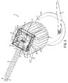
- FIG. 5 is an enlarged perspective view of the junction box portion of the lighting fixture of FIG. 1 shown in a partially open condition, the cylindrical cover 72 shown as transparent;
- FIG. 6 is a top perspective view of the chassis of the junction box of FIG. 5 ;
- FIG. 7 is a bottom perspective view of the junction box chassis of FIG. 6 ;
- FIG. 8 is a top perspective of the junction box of FIG. 5 without the cylindrical cover
- FIG. 9 is a top perspective view of the junction box of FIG. 8 taken from the opposite side;
- FIG. 10 is a bottom perspective view of the junction box of FIG. 8 ;
- FIG. 11 is a bottom perspective view of the junction box of FIG. 10 taken from the opposite side;
- FIG. 12 is a side elevational view of the junction box of FIG. 8 showing wiring in both compartments thereof;
- FIG. 13 is a perspective view of the junction box of FIG. 12 showing wiring in the input (supply) compartment thereof;
- FIG. 14 is a perspective view of the junction box of FIG. 12 showing wiring in the output compartment thereof.
- a lighting fixture comprises a lamp housing 10 , a junction box assembly 40 and a flexible metal conduit 30 interconnecting the lamp housing and the junction box and protecting wiring within.
- Lamp housing 10 comprises a metallic tubular lower body 12 , a finned metallic upper housing 16 and a metallic, generally square two-part top housing 18 (shown as transparent in FIGS. 2 , 3 and 4 ).
- Lower body 12 houses a removable reflector 13 having a bottom annular trim flange 14 ; and it has two tangential, oppositely directed retention springs 15 that removably secure the lamp housing 10 in a properly sized installation hole H in ceiling C, with trim flange 14 bearing against the lower surface of the ceiling.
- Junction box 40 simply rests on the ceiling near the lamp housing.
- Three screws 22 securely fasten the three-sided, U-shaped bottom half 20 of top housing 18 to fins of upper housing 16 .
- the inverted box-shaped top half 24 of top housing 18 fits over and is secured to the upstanding sides of bottom half 20 by two screws 26 .
- One end of conduit 30 is received in an aperture 28 in one side of top half 24 and is retained therein by a suitable wire-protecting metallic connector 32 , such as the flanged connector disclosed in U.S. Pat. No. 4,880,387 (incorporated herein by reference).
- the same or a similar connector 34 secures the other end of conduit 30 to an end of junction box 40 .
- the conductivity afforded by these connectors enables metallic conduit 30 to provide an electrical grounding path from lamp housing 10 to junction box 40 , which is grounded as described below.
- a lamp assembly 19 is mounted to the bottom of upper housing 16 so as to be disposed within lower body 12 when the lower body is joined to the upper housing. Light generated by the lamp assembly is dispersed and/or focused by reflector 13 , while heat generated by the lamp assembly is dissipated by the finned heat sink of upper housing 16 .
- “lamp assembly” means a light source of any type powered by electricity, such as an incandescent lamp (e.g., conventional tungsten filament or halogen), a compact fluorescent lamp, an LED light engine, etc.
- the lamp assembly is an LED light engine, such as a high output XSM LED module manufactured by Xicato (http://www.xicato.com/products.php).
- upper housing 16 is joined to lower body 12 , preferably by means of external threads 27 on the mounting ring of lamp assembly 19 , those threads mating with internal threads 29 at the upper end of lower body 12 .
- the inherent adjustability of this threaded connection accommodates small variations in the length of reflector 13 , which may be due to manufacturing tolerances, allowing for accurate close positioning of the small upper-end aperture of reflector 13 relative to lamp assembly 19 for proper optical performance.
- a nylon-tipped set screw 17 prevents relative rotation of the threaded parts after adjustment.
- Insulated conductors W in protective flexible conduit 30 emerge in top housing 18 , extend through upper housing 16 and are connected to lamp assembly 19 .
- conductors W terminate in top housing 18 in a first connector half 21 , which mates with a second connector half 23 wired via conductors 25 to lamp assembly 19 .
- Such a connector arrangement facilitates removal and replacement of lamp assembly 19 .
- twist-on connectors can be used in top housing 18 to connect conductors W to conductors 25 .
- Conductors W emerge from the other end of conduit 30 in junction box 40 , where they are connected to a power supply 42 as more fully described below.
- a flexible tether 36 that emerges in top housing 18 where it is secured by a crimped eye-lug 37 riveted at 38 to the top half 24 of that housing.
- the other end of tether 36 emerges from conduit 30 in junction box 40 where it is secured to junction box chassis 44 by a crimped eye-lug 46 and a screw 47 .
- the length of tether 36 is selected such that it functions as a strain relief cable to prevent undue strain on the conductors W and their connections, and preferably to prevent undue tensile loading on flexible conduit 30 .
- Tether 36 preferably is conductive and preferably is made of braided galvanized or stainless steel. If metallic, tether 36 provides an electrical grounding bond between lamp housing 10 and junction box 40 .
- the preferred path of tether 36 is through flexible conduit 30 as illustrated, but the tether instead could run externally of the conduit, optionally loosely tied to the conduit by tape, nylon ties or other means.
- chassis 44 closely surrounds power supply 42 , which is mounted in a generally rectangular central aperture 45 in the base of chassis 44 .
- a broad longitudinal mounting flange 48 protruding from one longer side of aperture 45 has two mounting slots 50 near its distal edge.
- Two additional mounting slots 52 are formed in the base of chassis 44 near the proximal end of flange 48 .
- two mounting straps 54 pass through slots 50 , 52 and surround power supply 42 to firmly secure it in position against flange 48 .
- mounting straps 54 are omitted from FIGS. 9-11 .
- Nylon cable ties may be used as mounting the straps; however, any suitable mounting hardware could be used depending on the configuration of the power supply and/or any mounting tabs it may have.
- Axially spaced circular end plates 60 , 62 are riveted at 63 to apertured tabs 56 , 58 , respectively, at the ends of chassis 44 .
- Each end plate has a peripheral notch 64 that accommodates a resilient spring clip 66 , which is riveted at 67 to a narrow longitudinal flange 68 protruding from one edge of chassis 44 .
- Each of the two spring clips 66 has a shoulder 70 that engages an end of sleeve-like cylindrical cover 72 (see FIGS. 1 and 2 ), the two shoulders acting as opposing stops to trap the cover in a closed position closely surrounding chassis 44 and end plates 60 , 62 . Inward finger pressure on either spring clip 66 allows its shoulder 70 to clear the end of cover 72 , which can then be slid open axially past the depressed spring clip as shown in FIG. 5 and completely removed, if desired.
- any other suitable arrangement could be used instead of the illustrated spring clips to releasably maintain the cover 72 in a closed position.
- Such devices could be mounted on chassis 44 , on one or both end plates 60 , 62 or on the cover 72 itself.
- each end plate 60 , 62 could carry a linearly or pivotally retractable member (spring-loaded or otherwise), which when extended acts as a stop against an end of the cover 72 to keep it closed.
- one or more screws could secure the cover to chassis flange 68 or to an adjacent tab carried by an end plate.
- a right circular cylinder is the preferred shape of the junction box, the shape of the end plates and the matching cross-section of the cylindrical cover could vary somewhat as long as the described functionality is not impaired.
- the maximum width of the junction box 40 should be no greater than the maximum width of the lamp housing 10 (excluding retention springs 15 ).
- Chassis 44 divides the interior of the junction box into two compartments 80 , 90 in which wiring for different voltages is separately maintained.
- power supply 42 is a step-down transformer (driver) that converts line (supply) voltage fed to input compartment 80 to a lower voltage for powering the LED light engine of lamp assembly 19 from output compartment 90 .
- the input leads 82 of power supply 42 are disposed in input compartment 80 (shown with plug-in connectors in FIGS. 12 and 13 ), while the lower voltage output and control leads 92 are disposed in output compartment 90 (shown with twist-on connectors in FIGS. 12 and 14 ).
- the term “power supply” broadly means any device that converts, conditions or otherwise modifies or adapts supplied electrical power for a specific load or application.
- End plate 60 has an opening 74 through which line voltage and ground conductors (not shown) are fed to input compartment 80 , which also houses a ground wire (see FIGS. 12 and 13 ) secured to chassis 44 by a screw 77 (see FIG. 11 ).
- Through branch wiring can be accommodated via opening 74 by using an appropriate duplex connector.
- End plate 62 has an opening that supports a conventional, outwardly projecting thermal protector 76 , which is connected to wiring in input compartment 80 (see FIGS. 12 and 13 ).
- End plate 62 also has an opening 78 in which an end of conduit 30 is received and is secured by connector 34 (see FIG. 5 ).
- Conductors W in conduit 30 thus communicate with lower voltage output compartment 90 , where they are connected to driver output leads 92 (see FIGS. 12 and 14 ).
- An opening in end plate 60 adjacent output compartment 90 is closed by a knockout 79 , which can be removed for the separate entry of low voltage control wiring, such as for a lamp dimming control.
- Cover 72 is released and slid open over conduit 30 in the direction of lamp housing 10 to expose input compartment 80 .
- Supply wiring above the ceiling is pulled through the fixture installation hole H, passed through and clamped in opening 74 (using an appropriate connector) and connected to input leads 82 and the fixture ground wire.
- Cover 72 is then slid closed and latched.
- Junction box 40 is then passed upward through the installation hole H followed by flexible conduit 30 .
- Junction box 40 simply rests on the upper surface of the ceiling. With retention springs 15 squeezed around lower body 12 , the lamp housing 10 is pushed upwardly into the installation hole until the springs pop out above the ceiling, locking the fixture in place. A slight clockwise twist of the reflector 13 seats it firmly against the ceiling.
- the fixture can be removed from the ceiling easily by first twisting the reflector 13 slightly counterclockwise while applying slight downward pressure. Once the retention springs 15 are accessible, they are squeezed together and the lamp housing is pulled down out of the installation hole, followed by flexible conduit 30 and junction box 40 .
Abstract
Description
Claims (34)
Priority Applications (3)
| Application Number | Priority Date | Filing Date | Title |
|---|---|---|---|
| US13/466,533 US8854796B2 (en) | 2011-05-09 | 2012-05-08 | Recessed lighting fixture and flexibly attached compact junction box |
| US14/494,919 US8995114B2 (en) | 2011-05-09 | 2014-09-24 | Recessed lighting fixture and flexibly attached compact junction box |
| US14/642,376 US9488350B2 (en) | 2011-05-09 | 2015-03-09 | Recessed lighting fixture and flexibly attached compact junction box |
Applications Claiming Priority (2)
| Application Number | Priority Date | Filing Date | Title |
|---|---|---|---|
| US201161483912P | 2011-05-09 | 2011-05-09 | |
| US13/466,533 US8854796B2 (en) | 2011-05-09 | 2012-05-08 | Recessed lighting fixture and flexibly attached compact junction box |
Related Child Applications (1)
| Application Number | Title | Priority Date | Filing Date |
|---|---|---|---|
| US14/494,919 Continuation US8995114B2 (en) | 2011-05-09 | 2014-09-24 | Recessed lighting fixture and flexibly attached compact junction box |
Publications (2)
| Publication Number | Publication Date |
|---|---|
| US20120287616A1 US20120287616A1 (en) | 2012-11-15 |
| US8854796B2 true US8854796B2 (en) | 2014-10-07 |
Family
ID=47141748
Family Applications (3)
| Application Number | Title | Priority Date | Filing Date |
|---|---|---|---|
| US13/466,533 Active 2033-04-26 US8854796B2 (en) | 2011-05-09 | 2012-05-08 | Recessed lighting fixture and flexibly attached compact junction box |
| US14/494,919 Active US8995114B2 (en) | 2011-05-09 | 2014-09-24 | Recessed lighting fixture and flexibly attached compact junction box |
| US14/642,376 Active 2032-07-06 US9488350B2 (en) | 2011-05-09 | 2015-03-09 | Recessed lighting fixture and flexibly attached compact junction box |
Family Applications After (2)
| Application Number | Title | Priority Date | Filing Date |
|---|---|---|---|
| US14/494,919 Active US8995114B2 (en) | 2011-05-09 | 2014-09-24 | Recessed lighting fixture and flexibly attached compact junction box |
| US14/642,376 Active 2032-07-06 US9488350B2 (en) | 2011-05-09 | 2015-03-09 | Recessed lighting fixture and flexibly attached compact junction box |
Country Status (1)
| Country | Link |
|---|---|
| US (3) | US8854796B2 (en) |
Cited By (10)
| Publication number | Priority date | Publication date | Assignee | Title |
|---|---|---|---|---|
| US9714760B2 (en) | 2015-09-11 | 2017-07-25 | Daniel Scoggin | Light fixture installation mounting device |
| US20170269371A1 (en) * | 2016-03-21 | 2017-09-21 | Hubbell Incorporated | Light fixture with narrow light distribution |
| US9903575B2 (en) | 2015-01-09 | 2018-02-27 | Abl Ip Holding Llc | High and low voltage separating driver brackets for lighting systems and methods for installation |
| US20190027881A1 (en) * | 2017-07-21 | 2019-01-24 | Canel Lighting Co., Ltd. | Powered Fixture System and Installation Thereof |
| US10859219B2 (en) | 2015-09-25 | 2020-12-08 | Hubbell Incorporated | Luminaire |
| WO2021174187A1 (en) * | 2020-02-28 | 2021-09-02 | Kohen Ran Roland | Recessing smart quick connect devices |
| US11196216B2 (en) | 2017-04-17 | 2021-12-07 | Ran Roland Kohen | Disconnecting and supporting quick release electrical fixtures |
| US11371684B1 (en) | 2021-03-31 | 2022-06-28 | Troy-CSL Lighting Inc. | Hinged driver housing for lighting system and lighting system including same |
| US11460184B2 (en) | 2017-03-05 | 2022-10-04 | Skyx Platforms Corp. | Modular smart quick connect device for electrical fixtures |
| US11916333B2 (en) | 2019-02-20 | 2024-02-27 | Skyx Platforms Corp. | Quick connect device with transverse release |
Families Citing this family (20)
| Publication number | Priority date | Publication date | Assignee | Title |
|---|---|---|---|---|
| US10054274B2 (en) * | 2012-03-23 | 2018-08-21 | Cree, Inc. | Direct attach ceiling-mounted solid state downlights |
| CN203920581U (en) * | 2012-07-30 | 2014-11-05 | 钱自德 | Built-in automotive side-looking blind spot mirror |
| US20140063629A1 (en) * | 2012-09-02 | 2014-03-06 | Davy Zide Qian | Interior side mirror for side blind spot of a car |
| US9441634B2 (en) * | 2013-01-11 | 2016-09-13 | Daniel S. Spiro | Integrated ceiling device with mechanical arrangement for a light source |
| DE202013100276U1 (en) * | 2013-01-21 | 2013-02-01 | Briloner Leuchten Gmbh | Light-emitting diode module and luminaire with at least one light-emitting diode module |
| JP2014146533A (en) * | 2013-01-30 | 2014-08-14 | Rohm Co Ltd | Led lighting device |
| US10001270B2 (en) | 2013-04-05 | 2018-06-19 | Cooper Technologies Company | Housings and related components for luminaires |
| US9062837B2 (en) | 2013-04-05 | 2015-06-23 | Cooper Technologies Company | Housings and related components for luminaires |
| JP6115346B2 (en) * | 2013-06-19 | 2017-04-19 | 三菱電機株式会社 | Downlight |
| US20150369465A1 (en) * | 2014-06-19 | 2015-12-24 | RSI Development LLC | Lighting system |
| MX364065B (en) * | 2015-04-30 | 2019-04-11 | Hubbell Inc | Control device for solid state lighting fixtures. |
| GB201518480D0 (en) * | 2015-10-19 | 2015-12-02 | Aurora Ltd | Downlight with detachable electronic module |
| US10168032B2 (en) * | 2016-12-02 | 2019-01-01 | Les Produits Sunforce Inc. | Exterior lamp mounting adaptor |
| GB2559961B (en) * | 2017-02-16 | 2019-07-17 | Aurora Ltd | Improved downlight with a detachable electronic module |
| USD877956S1 (en) * | 2017-09-28 | 2020-03-10 | Hubbell Incorporated | Luminaire |
| US10948167B2 (en) | 2017-11-17 | 2021-03-16 | Hubbell Incorporated | Light fixture with adjustable light distribution assembly |
| US11054118B2 (en) * | 2019-04-24 | 2021-07-06 | David Sherman | Apparatus to detachably attach LED light fixture to ceiling or recessed lighting fixture housing |
| CN113795707A (en) * | 2019-05-09 | 2021-12-14 | 昕诺飞控股有限公司 | Lamp driver and installation method |
| EP4065879A4 (en) | 2019-11-25 | 2023-12-06 | Molex, LLC | Led lighting fixture with interconnect |
| CA3192778A1 (en) * | 2020-07-10 | 2022-01-13 | HLI Solutions, Inc. | Modular junction box for downlight luminaire |
Citations (34)
| Publication number | Priority date | Publication date | Assignee | Title |
|---|---|---|---|---|
| US861813A (en) | 1907-03-02 | 1907-07-30 | Frank B Cook | Junction-box. |
| US2887525A (en) | 1956-09-25 | 1959-05-19 | Alexander J Lewus | Electrical wiring apparatus |
| US4070083A (en) | 1977-01-31 | 1978-01-24 | Dipalma Joseph | Electrical power line extension |
| US4234146A (en) | 1978-03-14 | 1980-11-18 | Febs International, Ltd. | Flat type cable suspension structure |
| US4323724A (en) | 1980-05-01 | 1982-04-06 | Shine William P | Unitary insertable self-anchoring poke-thru wiring device |
| US4518830A (en) | 1982-06-25 | 1985-05-21 | At&T Bell Laboratories | Armored telephone cord with a longitudinal strength member |
| US4829410A (en) | 1987-06-17 | 1989-05-09 | Emerson Electric Co. | Ceiling mounted luminaire housing system |
| US4880387A (en) | 1988-10-03 | 1989-11-14 | Ibc Corporation | Connector for flexible electrical conduit |
| US4900266A (en) | 1989-03-08 | 1990-02-13 | Gsi Corporation | Strain relief system for connecting cables |
| US5370546A (en) | 1993-01-08 | 1994-12-06 | National Cathode Corp. | Lamp holder for cold cathode fluorescent lamp |
| US5588737A (en) * | 1994-11-10 | 1996-12-31 | Thomas Industries, Inc. | Modular recessed lighting system |
| US5664869A (en) | 1996-02-14 | 1997-09-09 | Bitton; Jacques | Low voltage potlamp system |
| US5957574A (en) | 1996-03-04 | 1999-09-28 | Nsi Enterprises, Inc. | Pan assemblies formed of strap-like stock for mounting recessed lighting in ceilings and the like |
| US6123438A (en) * | 1998-08-24 | 2000-09-26 | Nsi Enterprises, Inc. | Insulation shield for recessed downlighting fixtures |
| US6428190B1 (en) | 2000-05-09 | 2002-08-06 | Acuity Brands, Inc. | Electrical power cord manager for a lighting fixture |
| US6659627B2 (en) | 2002-02-28 | 2003-12-09 | Canlyte Inc. | Light fixture assembly |
| US6699063B2 (en) | 2001-02-14 | 2004-03-02 | Roland Lebender | Cable assembly having strain relief mechanism and housing incorporating such cable assembly |
| US6831222B2 (en) | 2002-08-14 | 2004-12-14 | Darrell Pastuch | Weatherproof junction box |
| US6940016B1 (en) | 2003-08-06 | 2005-09-06 | Desa Ip, Llc | Electrical rough-in box for low voltage transformer |
| US6994457B2 (en) | 2003-08-13 | 2006-02-07 | Jji Lighting Group, Inc. | Recessed downlight lighting apparatus |
| US7078619B2 (en) * | 2002-05-25 | 2006-07-18 | Geo-X Systems, Ltd. | Universal seismic data acquisition module |
| US7118254B2 (en) | 2004-04-20 | 2006-10-10 | Genlyte Thomas Group, Llc | Recessed downlight mounting fixture |
| US20060232970A1 (en) | 2005-04-13 | 2006-10-19 | Ken Cheng | Hanging decorative lights |
| US7148431B2 (en) | 2004-06-07 | 2006-12-12 | Thomas & Betts International, Inc. | Armored cable connector |
| US7401961B2 (en) | 2002-05-02 | 2008-07-22 | Fatzer Ag | Luminous wire rope |
| US7438433B1 (en) | 2007-08-31 | 2008-10-21 | Hubbell Incorporated | Lighting fixture assembly with easy access junction box |
| US7586039B1 (en) * | 2008-01-09 | 2009-09-08 | Arlington Industries, Inc. | Hole saw electrical box for direct mounting of electrical fixtures or devices to a wall |
| US7677770B2 (en) | 2007-01-09 | 2010-03-16 | Lighting Science Group Corporation | Thermally-managed LED-based recessed down lights |
| US7824213B1 (en) * | 2009-07-27 | 2010-11-02 | Hubbell Incorporated | One-piece electrical cable connector having a retaining spring |
| US7905637B2 (en) | 2008-01-30 | 2011-03-15 | Canlyte Inc. | Transformer assembly and light fixture assembly using same |
| US8021007B2 (en) | 2008-03-28 | 2011-09-20 | Thomas & Betts International, Inc. | Concealed emergency lighting equipment with complete retrofit housing and method of installation |
| US8287142B2 (en) | 2008-05-16 | 2012-10-16 | Cree, Inc. | Conversion kit for lighting assemblies |
| US8480268B2 (en) * | 2010-08-18 | 2013-07-09 | Hubbell Incorporated | Electrical box and ballast mounting assembly for retrofitting recessed lighting fixtures |
| US20130312995A1 (en) * | 2009-05-22 | 2013-11-28 | Solaredge Technologies Ltd. | Electrically Isolated Heat Dissipating Junction Box |
Family Cites Families (6)
| Publication number | Priority date | Publication date | Assignee | Title |
|---|---|---|---|---|
| US6079851A (en) * | 1997-02-26 | 2000-06-27 | The Whitaker Corporation | Fluorescent lighting fixture having two separate end supports, separate integral ballast subassembly and lamps sockets, and hood positionable above end supports for mounting in or below opening in suspended ceiling |
| US6254257B1 (en) * | 1998-11-16 | 2001-07-03 | Progress Lighting | Recessed light fixture and reflector |
| US7357541B2 (en) * | 2004-04-05 | 2008-04-15 | Genlyte Thomas Group, Llc | Enclosure for socket cup for snap-in electrical quick connectors |
| US7748868B2 (en) * | 2006-11-14 | 2010-07-06 | Focal Point, L.L.C. | Recessed luminaire |
| US7614769B2 (en) * | 2007-11-23 | 2009-11-10 | Sell Timothy L | LED conversion system for recessed lighting |
| US8506134B2 (en) * | 2010-08-18 | 2013-08-13 | Hubbell Incorporated | Retrofit mounting assembly for recessed lighting fixtures |
-
2012
- 2012-05-08 US US13/466,533 patent/US8854796B2/en active Active
-
2014
- 2014-09-24 US US14/494,919 patent/US8995114B2/en active Active
-
2015
- 2015-03-09 US US14/642,376 patent/US9488350B2/en active Active
Patent Citations (34)
| Publication number | Priority date | Publication date | Assignee | Title |
|---|---|---|---|---|
| US861813A (en) | 1907-03-02 | 1907-07-30 | Frank B Cook | Junction-box. |
| US2887525A (en) | 1956-09-25 | 1959-05-19 | Alexander J Lewus | Electrical wiring apparatus |
| US4070083A (en) | 1977-01-31 | 1978-01-24 | Dipalma Joseph | Electrical power line extension |
| US4234146A (en) | 1978-03-14 | 1980-11-18 | Febs International, Ltd. | Flat type cable suspension structure |
| US4323724A (en) | 1980-05-01 | 1982-04-06 | Shine William P | Unitary insertable self-anchoring poke-thru wiring device |
| US4518830A (en) | 1982-06-25 | 1985-05-21 | At&T Bell Laboratories | Armored telephone cord with a longitudinal strength member |
| US4829410A (en) | 1987-06-17 | 1989-05-09 | Emerson Electric Co. | Ceiling mounted luminaire housing system |
| US4880387A (en) | 1988-10-03 | 1989-11-14 | Ibc Corporation | Connector for flexible electrical conduit |
| US4900266A (en) | 1989-03-08 | 1990-02-13 | Gsi Corporation | Strain relief system for connecting cables |
| US5370546A (en) | 1993-01-08 | 1994-12-06 | National Cathode Corp. | Lamp holder for cold cathode fluorescent lamp |
| US5588737A (en) * | 1994-11-10 | 1996-12-31 | Thomas Industries, Inc. | Modular recessed lighting system |
| US5664869A (en) | 1996-02-14 | 1997-09-09 | Bitton; Jacques | Low voltage potlamp system |
| US5957574A (en) | 1996-03-04 | 1999-09-28 | Nsi Enterprises, Inc. | Pan assemblies formed of strap-like stock for mounting recessed lighting in ceilings and the like |
| US6123438A (en) * | 1998-08-24 | 2000-09-26 | Nsi Enterprises, Inc. | Insulation shield for recessed downlighting fixtures |
| US6428190B1 (en) | 2000-05-09 | 2002-08-06 | Acuity Brands, Inc. | Electrical power cord manager for a lighting fixture |
| US6699063B2 (en) | 2001-02-14 | 2004-03-02 | Roland Lebender | Cable assembly having strain relief mechanism and housing incorporating such cable assembly |
| US6659627B2 (en) | 2002-02-28 | 2003-12-09 | Canlyte Inc. | Light fixture assembly |
| US7401961B2 (en) | 2002-05-02 | 2008-07-22 | Fatzer Ag | Luminous wire rope |
| US7078619B2 (en) * | 2002-05-25 | 2006-07-18 | Geo-X Systems, Ltd. | Universal seismic data acquisition module |
| US6831222B2 (en) | 2002-08-14 | 2004-12-14 | Darrell Pastuch | Weatherproof junction box |
| US6940016B1 (en) | 2003-08-06 | 2005-09-06 | Desa Ip, Llc | Electrical rough-in box for low voltage transformer |
| US6994457B2 (en) | 2003-08-13 | 2006-02-07 | Jji Lighting Group, Inc. | Recessed downlight lighting apparatus |
| US7118254B2 (en) | 2004-04-20 | 2006-10-10 | Genlyte Thomas Group, Llc | Recessed downlight mounting fixture |
| US7148431B2 (en) | 2004-06-07 | 2006-12-12 | Thomas & Betts International, Inc. | Armored cable connector |
| US20060232970A1 (en) | 2005-04-13 | 2006-10-19 | Ken Cheng | Hanging decorative lights |
| US7677770B2 (en) | 2007-01-09 | 2010-03-16 | Lighting Science Group Corporation | Thermally-managed LED-based recessed down lights |
| US7438433B1 (en) | 2007-08-31 | 2008-10-21 | Hubbell Incorporated | Lighting fixture assembly with easy access junction box |
| US7586039B1 (en) * | 2008-01-09 | 2009-09-08 | Arlington Industries, Inc. | Hole saw electrical box for direct mounting of electrical fixtures or devices to a wall |
| US7905637B2 (en) | 2008-01-30 | 2011-03-15 | Canlyte Inc. | Transformer assembly and light fixture assembly using same |
| US8021007B2 (en) | 2008-03-28 | 2011-09-20 | Thomas & Betts International, Inc. | Concealed emergency lighting equipment with complete retrofit housing and method of installation |
| US8287142B2 (en) | 2008-05-16 | 2012-10-16 | Cree, Inc. | Conversion kit for lighting assemblies |
| US20130312995A1 (en) * | 2009-05-22 | 2013-11-28 | Solaredge Technologies Ltd. | Electrically Isolated Heat Dissipating Junction Box |
| US7824213B1 (en) * | 2009-07-27 | 2010-11-02 | Hubbell Incorporated | One-piece electrical cable connector having a retaining spring |
| US8480268B2 (en) * | 2010-08-18 | 2013-07-09 | Hubbell Incorporated | Electrical box and ballast mounting assembly for retrofitting recessed lighting fixtures |
Non-Patent Citations (3)
| Title |
|---|
| Lightolier Instruction Sheet No. IS:C2L-DL FIK, Philips Group, 2009. |
| Lightolier Instruction Sheet No. IS:C2L—DL FIK, Philips Group, 2009. |
| Prima Catalog Pose for Cat. No. 8742, Prima Lighting, 2009. |
Cited By (13)
| Publication number | Priority date | Publication date | Assignee | Title |
|---|---|---|---|---|
| US9903575B2 (en) | 2015-01-09 | 2018-02-27 | Abl Ip Holding Llc | High and low voltage separating driver brackets for lighting systems and methods for installation |
| US9714760B2 (en) | 2015-09-11 | 2017-07-25 | Daniel Scoggin | Light fixture installation mounting device |
| US10859219B2 (en) | 2015-09-25 | 2020-12-08 | Hubbell Incorporated | Luminaire |
| US11268666B2 (en) | 2016-03-21 | 2022-03-08 | Hubbell Incorporated | Light fixture with narrow light distribution |
| US10502375B2 (en) * | 2016-03-21 | 2019-12-10 | Hubbell Incorporated | Light fixture with narrow light distribution |
| US20170269371A1 (en) * | 2016-03-21 | 2017-09-21 | Hubbell Incorporated | Light fixture with narrow light distribution |
| US11460184B2 (en) | 2017-03-05 | 2022-10-04 | Skyx Platforms Corp. | Modular smart quick connect device for electrical fixtures |
| US11196216B2 (en) | 2017-04-17 | 2021-12-07 | Ran Roland Kohen | Disconnecting and supporting quick release electrical fixtures |
| US10424888B2 (en) * | 2017-07-21 | 2019-09-24 | Canel Lighting Co., Ltd. | Powered fixture system and installation thereof |
| US20190027881A1 (en) * | 2017-07-21 | 2019-01-24 | Canel Lighting Co., Ltd. | Powered Fixture System and Installation Thereof |
| US11916333B2 (en) | 2019-02-20 | 2024-02-27 | Skyx Platforms Corp. | Quick connect device with transverse release |
| WO2021174187A1 (en) * | 2020-02-28 | 2021-09-02 | Kohen Ran Roland | Recessing smart quick connect devices |
| US11371684B1 (en) | 2021-03-31 | 2022-06-28 | Troy-CSL Lighting Inc. | Hinged driver housing for lighting system and lighting system including same |
Also Published As
| Publication number | Publication date |
|---|---|
| US20150260383A1 (en) | 2015-09-17 |
| US20150009675A1 (en) | 2015-01-08 |
| US8995114B2 (en) | 2015-03-31 |
| US9488350B2 (en) | 2016-11-08 |
| US20120287616A1 (en) | 2012-11-15 |
Similar Documents
| Publication | Publication Date | Title |
|---|---|---|
| US9488350B2 (en) | Recessed lighting fixture and flexibly attached compact junction box | |
| US20220042664A1 (en) | Alternate junction box and arrangement for lighting apparatus | |
| US10054274B2 (en) | Direct attach ceiling-mounted solid state downlights | |
| CA2791108C (en) | Method, apparatus and system for connecting a light emitting diode light fixture to a mains power conductor | |
| US7628504B2 (en) | Light fixture retrofitting apparatus and method | |
| US9109783B1 (en) | Secondary enclosure for light-emitting diode-based lighting system | |
| US8950909B2 (en) | Light fixture with concealed wireway | |
| US9970634B1 (en) | Recessed luminaire for remodel applications | |
| US10458628B2 (en) | Led luminaire with adaptable installation kit | |
| JP6162474B2 (en) | Cord length adjustment mechanism | |
| US8382344B2 (en) | Remote ballast assembly | |
| JP2018147590A (en) | Luminaire | |
| JP7180082B2 (en) | lighting equipment | |
| JP7428971B2 (en) | lighting equipment | |
| JP2020113399A (en) | Illuminating device | |
| US20130100629A1 (en) | Access plate adapter for electrical fixture | |
| JP7054805B2 (en) | Sockets and lighting fixtures | |
| JP6162475B2 (en) | Cord length adjusting mechanism and lighting apparatus including the same | |
| JP2019129113A (en) | Illuminating device | |
| JP2018101611A (en) | Luminaire | |
| JP2020136209A (en) | Socket and lighting fixture | |
| JP7402489B2 (en) | lighting equipment | |
| JP7152699B2 (en) | lighting equipment | |
| US10281118B2 (en) | Tool-less apparatus and method for securing lighting enclosure cover | |
| US10167980B2 (en) | Tray bracket for mounting electrical components |
Legal Events
| Date | Code | Title | Description |
|---|---|---|---|
| AS | Assignment |
Owner name: HUBBELL INCORPORATED, CONNECTICUT Free format text: ASSIGNMENT OF ASSIGNORS INTEREST;ASSIGNOR:WILCOX, SHAWN A.;REEL/FRAME:028657/0917 Effective date: 20120524 |
|
| STCF | Information on status: patent grant |
Free format text: PATENTED CASE |
|
| MAFP | Maintenance fee payment |
Free format text: PAYMENT OF MAINTENANCE FEE, 4TH YEAR, LARGE ENTITY (ORIGINAL EVENT CODE: M1551) Year of fee payment: 4 |
|
| AS | Assignment |
Owner name: HUBBELL LIGHTING, INC., CONNECTICUT Free format text: NUNC PRO TUNC ASSIGNMENT;ASSIGNOR:HUBBELL INCORPORATED;REEL/FRAME:058838/0162 Effective date: 20220112 |
|
| AS | Assignment |
Owner name: ALLY BANK, AS COLLATERAL AGENT, NEW YORK Free format text: SECURITY AGREEMENT;ASSIGNORS:HUBBELL LIGHTING, INC.;LITECONTROL CORPORATION;CURRENT LIGHTING SOLUTIONS, LLC;AND OTHERS;REEL/FRAME:058982/0844 Effective date: 20220201 |
|
| AS | Assignment |
Owner name: ATLANTIC PARK STRATEGIC CAPITAL FUND, L.P., AS COLLATERAL AGENT, NEW YORK Free format text: SECURITY INTEREST;ASSIGNORS:HUBBELL LIGHTING, INC.;LITECONTROL CORPORATION;CURRENT LIGHTING SOLUTIONS, LLC;AND OTHERS;REEL/FRAME:059034/0469 Effective date: 20220201 |
|
| FEPP | Fee payment procedure |
Free format text: MAINTENANCE FEE REMINDER MAILED (ORIGINAL EVENT CODE: REM.); ENTITY STATUS OF PATENT OWNER: LARGE ENTITY |
|
| FEPP | Fee payment procedure |
Free format text: 7.5 YR SURCHARGE - LATE PMT W/IN 6 MO, LARGE ENTITY (ORIGINAL EVENT CODE: M1555); ENTITY STATUS OF PATENT OWNER: LARGE ENTITY |
|
| MAFP | Maintenance fee payment |
Free format text: PAYMENT OF MAINTENANCE FEE, 8TH YEAR, LARGE ENTITY (ORIGINAL EVENT CODE: M1552); ENTITY STATUS OF PATENT OWNER: LARGE ENTITY Year of fee payment: 8 |
|
| AS | Assignment |
Owner name: ALLY BANK, AS COLLATERAL AGENT, NEW YORK Free format text: CORRECTIVE ASSIGNMENT TO CORRECT THE PATENT NUMBER 10841994 TO PATENT NUMBER 11570872 PREVIOUSLY RECORDED ON REEL 058982 FRAME 0844. ASSIGNOR(S) HEREBY CONFIRMS THE SECURITY AGREEMENT;ASSIGNORS:HUBBELL LIGHTING, INC.;LITECONTROL CORPORATION;CURRENT LIGHTING SOLUTIONS, LLC;AND OTHERS;REEL/FRAME:066355/0455 Effective date: 20220201 |
|
| AS | Assignment |
Owner name: ATLANTIC PARK STRATEGIC CAPITAL FUND, L.P., AS COLLATERAL AGENT, NEW YORK Free format text: CORRECTIVE ASSIGNMENT TO CORRECT THE PATENT NUMBER PREVIOUSLY RECORDED AT REEL: 059034 FRAME: 0469. ASSIGNOR(S) HEREBY CONFIRMS THE SECURITY INTEREST;ASSIGNORS:HUBBELL LIGHTING, INC.;LITECONTROL CORPORATION;CURRENT LIGHTING SOLUTIONS, LLC;AND OTHERS;REEL/FRAME:066372/0590 Effective date: 20220201 |