US8866889B2 - In-home depth camera calibration - Google Patents
In-home depth camera calibration Download PDFInfo
- Publication number
- US8866889B2 US8866889B2 US12/939,038 US93903810A US8866889B2 US 8866889 B2 US8866889 B2 US 8866889B2 US 93903810 A US93903810 A US 93903810A US 8866889 B2 US8866889 B2 US 8866889B2
- Authority
- US
- United States
- Prior art keywords
- depth
- error
- sensor
- true
- user
- Prior art date
- Legal status (The legal status is an assumption and is not a legal conclusion. Google has not performed a legal analysis and makes no representation as to the accuracy of the status listed.)
- Active, expires
Links
Images


Classifications
-
- H—ELECTRICITY
- H04—ELECTRIC COMMUNICATION TECHNIQUE
- H04N—PICTORIAL COMMUNICATION, e.g. TELEVISION
- H04N13/00—Stereoscopic video systems; Multi-view video systems; Details thereof
- H04N13/30—Image reproducers
- H04N13/327—Calibration thereof
-
- H04N13/0425—
-
- A—HUMAN NECESSITIES
- A63—SPORTS; GAMES; AMUSEMENTS
- A63F—CARD, BOARD, OR ROULETTE GAMES; INDOOR GAMES USING SMALL MOVING PLAYING BODIES; VIDEO GAMES; GAMES NOT OTHERWISE PROVIDED FOR
- A63F13/00—Video games, i.e. games using an electronically generated display having two or more dimensions
- A63F13/20—Input arrangements for video game devices
- A63F13/21—Input arrangements for video game devices characterised by their sensors, purposes or types
- A63F13/213—Input arrangements for video game devices characterised by their sensors, purposes or types comprising photodetecting means, e.g. cameras, photodiodes or infrared cells
-
- A—HUMAN NECESSITIES
- A63—SPORTS; GAMES; AMUSEMENTS
- A63F—CARD, BOARD, OR ROULETTE GAMES; INDOOR GAMES USING SMALL MOVING PLAYING BODIES; VIDEO GAMES; GAMES NOT OTHERWISE PROVIDED FOR
- A63F13/00—Video games, i.e. games using an electronically generated display having two or more dimensions
- A63F13/20—Input arrangements for video game devices
- A63F13/22—Setup operations, e.g. calibration, key configuration or button assignment
-
- G—PHYSICS
- G06—COMPUTING; CALCULATING OR COUNTING
- G06F—ELECTRIC DIGITAL DATA PROCESSING
- G06F3/00—Input arrangements for transferring data to be processed into a form capable of being handled by the computer; Output arrangements for transferring data from processing unit to output unit, e.g. interface arrangements
- G06F3/01—Input arrangements or combined input and output arrangements for interaction between user and computer
- G06F3/017—Gesture based interaction, e.g. based on a set of recognized hand gestures
-
- G06T7/002—
-
- G06T7/0075—
-
- G—PHYSICS
- G06—COMPUTING; CALCULATING OR COUNTING
- G06T—IMAGE DATA PROCESSING OR GENERATION, IN GENERAL
- G06T7/00—Image analysis
- G06T7/80—Analysis of captured images to determine intrinsic or extrinsic camera parameters, i.e. camera calibration
-
- H04N13/0022—
-
- H04N13/0271—
-
- H—ELECTRICITY
- H04—ELECTRIC COMMUNICATION TECHNIQUE
- H04N—PICTORIAL COMMUNICATION, e.g. TELEVISION
- H04N13/00—Stereoscopic video systems; Multi-view video systems; Details thereof
- H04N13/10—Processing, recording or transmission of stereoscopic or multi-view image signals
- H04N13/106—Processing image signals
- H04N13/128—Adjusting depth or disparity
-
- H—ELECTRICITY
- H04—ELECTRIC COMMUNICATION TECHNIQUE
- H04N—PICTORIAL COMMUNICATION, e.g. TELEVISION
- H04N13/00—Stereoscopic video systems; Multi-view video systems; Details thereof
- H04N13/20—Image signal generators
- H04N13/271—Image signal generators wherein the generated image signals comprise depth maps or disparity maps
-
- G—PHYSICS
- G06—COMPUTING; CALCULATING OR COUNTING
- G06T—IMAGE DATA PROCESSING OR GENERATION, IN GENERAL
- G06T2207/00—Indexing scheme for image analysis or image enhancement
- G06T2207/10—Image acquisition modality
- G06T2207/10016—Video; Image sequence
- G06T2207/10021—Stereoscopic video; Stereoscopic image sequence
-
- G—PHYSICS
- G06—COMPUTING; CALCULATING OR COUNTING
- G06T—IMAGE DATA PROCESSING OR GENERATION, IN GENERAL
- G06T2207/00—Indexing scheme for image analysis or image enhancement
- G06T2207/10—Image acquisition modality
- G06T2207/10028—Range image; Depth image; 3D point clouds
-
- G—PHYSICS
- G06—COMPUTING; CALCULATING OR COUNTING
- G06T—IMAGE DATA PROCESSING OR GENERATION, IN GENERAL
- G06T2207/00—Indexing scheme for image analysis or image enhancement
- G06T2207/30—Subject of image; Context of image processing
- G06T2207/30196—Human being; Person
Definitions
- computing applications such as computer games and multimedia applications used controllers, remotes, keyboards, mice, or the like to allow users to manipulate game characters or other aspects of an application.
- computer games and multimedia applications have begun employing cameras and software gesture recognition engines to provide a natural user interface (“NUI”).
- NUI natural user interface
- user gestures and speech are detected, interpreted and used to control game characters or other aspects of an application.
- NUI systems use three-dimensional (3-D) depth cameras to capture 3-D data of a scene.
- Depth cameras require several components to be precisely aligned in order to properly measure depth. Even a slight misalignment can result in significant depth measurement error. Misalignment may occur due to a variety of conditions, including for example improper manufacturing, extreme temperatures or other environmental factors, dropping the camera or other physical damage, etc.
- the depth Once the alignment is changed, the depth may be improperly reported in a number of ways. The results of this distortion can cause a shift in the camera's depth range, a transformation of an object's dimensions, or a variety of other distortions may occur. It is therefore desirable to provide a system for calibrating a depth camera to capture an accurate depth image, preferably with minimal impact on the user experience.
- the present technology relates to recalibrating a depth sensor used in a NUI system.
- the NUI system in general includes a capture device including a depth sensor and an RGB sensor.
- the depth projector may emit light onto a scene, which light is reflected back and sensed by the depth sensor and RGB sensor.
- the depth sensor uses the reflected light to determine the depth of objects within the scene.
- the present technology relates to a system for recalibrating a depth sensor to correct for any depth measurement error which may occur after factory calibration of the depth sensor.
- the present system obtains a true depth measurement to an object in a field of view.
- the system compares the true depth measurement to a depth measurement provided by the depth sensor to define an error model of the deviation.
- the present system provides a variety of methods for determining true depth measurements of one or more objects in a scene independently of the depth measurement obtained from the depth sensor.
- the depth sensor may simply be adjusted to the true depth.
- more complex mathematical schemas may be developed to model depth error. The depth error may then be compensated for by minimizing the depth error.
- One example of the present technology relates to a method of recalibrating a depth sensor of a natural user interface, the depth sensor capturing image data from a 3-D space.
- the method comprising the steps: (a) measuring a depth value of at least one sample point in the 3-D space using the depth sensor; (b) determining a true depth value of the at least one sample point independently of the measurement of said step (a); (c) modeling a depth error resulting from a deviation in the true depth determined in said step (b) and the depth measured in said step (a); and (d) correcting the depth measurements made by the depth sensor using the depth error modeled in said step (c).
- a further example of the present technology relates to a computer-readable storage medium including instructions for programming a processor to perform a method of recalibrating a depth sensor of a natural user interface, the depth sensor capturing image data from a 3-D space.
- the method comprising the steps: (a) measuring the depth of two or more points on a calibration object within the 3-D space using the depth sensor; (b) determining the true depth of the two or more points on the calibration object independently of the depth sensor; (c) modeling a depth error resulting from a deviation in the true depth determined in said step (b) and the depth measured in said step (a); and (d) compensating depth measurements made by the depth sensor using the depth error modeled in said step (c).
- the present technology relates to a system for recalibrating a depth sensor of a natural user interface, the depth sensor capturing image data from a 3-D space, the system comprising: a calibration object positioned within the 3-D space; and a computing device associated with the depth sensor, the computing device including a recalibration engine for comparing a true depth values of points on the calibration object in the 3-D space against depth values measured by the depth sensor, and deriving an error model which describes a deviation between the true depth values and the depth values measured by the depth sensor.
- FIG. 1 illustrates an example embodiment of a target recognition, analysis, and tracking system.
- FIG. 2 illustrates a further example embodiment of a target recognition, analysis, and tracking system.
- FIG. 3 illustrates an example embodiment of a capture device that may be used in a target recognition, analysis, and tracking system.
- FIG. 4 is a flowchart for calibrating a depth sensor according to a first embodiment of the present technology.
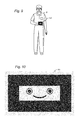
- FIG. 5 is an illustration of a user in a field of view of a capture device.
- FIG. 6 is a depth image of the user of FIG. 5 .
- FIG. 7 is a high level flowchart for calibrating a depth sensor according to a second embodiment of the present technology.
- FIG. 8 is a graph of sample points measured by a depth sensor and the true determined depth of the same sample points.
- FIG. 9 is an illustration of a user holding a calibration object positioned in a field of view of a capture device.
- FIG. 10 is an enlarged view of the calibration object.
- FIG. 11 is an enlarged view of the calibration object showing reference points which may be identified by the capture device.
- FIG. 12 is a view of the calibration object displayed to the user with a target for positioning the calibration object at a certain depth from the capture device.
- FIG. 13 is a flowchart for detecting points in the calibration object.
- FIG. 14 is an illustration of a plane of the calibration object relative to a coordinate system of the depth camera and relative to a coordinate system of the RGB camera.
- FIG. 15 is a flowchart for translating points in the plane of the calibration object to a reference frame of the RGB camera and then determining an error function based on the sample points measured by the RGB camera.
- FIG. 16 is a top view of a light ray projected from a projector, reflecting off of a sample point and incident on the depth sensor.
- FIG. 17 is a top view as in FIG. 16 , showing an error in the depth optics and a method for determining the error according to a third embodiment of the present technology.
- FIG. 18 is a graph of depth error over a range of error angles E.
- FIG. 19 is a graph of a depth error across the field of view.
- FIG. 20 is a graph of points of an object measured by an operation for determining true depth of the points, and the same points measured by the depth sensor and distorted by a depth error.
- FIG. 21 is a graph showing the degree and location of the distortion in the graph of FIG. 20 .
- FIG. 22 shows a field of view including a generalized transformation from depth-camera space to world space, with correction for the misalignment angle E.
- FIG. 23 shows two sets of points on a rigid body measured at two different locations according to a fourth embodiment of the present technology.
- FIG. 24A illustrates an example embodiment of a computing device that may be used to interpret one or more gestures in a target recognition, analysis, and tracking system.
- FIG. 24B illustrates another example embodiment of a computing device that may be used to interpret one or more gestures in a target recognition, analysis, and tracking system.
- FIGS. 1-24B in general relate to a system for calibrating a depth camera.
- the system in general obtains an objective measurement of distance between a depth camera and one or more objects in a scene, referred to herein as true depth.
- the system compares the true depth measurement to the depth measurement provided by the depth camera at one or more points and determines an error function describing an error in the depth camera measurement.
- the depth camera may then be recalibrated to correct for the error.
- the objective measurement of distance to one or more objects in a scene may be accomplished by a variety of systems and methods. These systems and methods are described below.
- the hardware for implementing the present technology includes a target recognition, analysis, and tracking system 10 which may be used to recognize, analyze, and/or track a human target such as the user 18 .
- Embodiments of the target recognition, analysis, and tracking system 10 include a computing environment 12 for executing a gaming or other application.
- the computing environment 12 may include hardware components and/or software components such that computing environment 12 may be used to execute applications such as gaming and non-gaming applications.
- computing environment 12 may include a processor such as a standardized processor, a specialized processor, a microprocessor, or the like that may execute, instructions stored on a processor readable storage device for performing processes described herein.
- the system 10 further includes a capture device 20 for capturing image and audio data relating to one or more users and/or objects sensed by the capture device.
- the capture device 20 may be used to capture information relating to movements, gestures and speech of one or more users, which information is received by the computing environment and used to render, interact with and/or control aspects of a gaming or other application. Examples of the computing environment 12 and capture device 20 are explained in greater detail below.
- Embodiments of the target recognition, analysis and tracking system 10 may be connected to an audio/visual device 16 having a display 14 .
- the device 16 may for example be a television, a monitor, a high-definition television (HDTV), or the like that may provide game or application visuals and/or audio to a user.
- the computing environment 12 may include a video adapter such as a graphics card and/or an audio adapter such as a sound card that may provide audio/visual signals associated with the game or other application.
- the audio/visual device 16 may receive the audio/visual signals from the computing environment 12 and may then output the game or application visuals and/or audio associated with the audio/visual signals to the user 18 .
- the audio/visual device 16 may be connected to the computing environment 12 via, for example, an S-Video cable, a coaxial cable, an HDMI cable, a DVI cable, a VGA cable, a component video cable, or the like.
- the computing environment 12 , the A/V device 16 and the capture device 20 may cooperate to render an avatar or on-screen character 19 on display 14 .
- the avatar 19 mimics the movements of the user 18 in real world space so that the user 18 may perform movements and gestures which control the movements and actions of the avatar 19 on the display 14 .
- the application executing on the computing environment 12 may be a soccer game that the user 18 may be playing.
- the computing environment 12 may use the audiovisual display 14 to provide a visual representation of an avatar 19 in form of a soccer player controlled by the user.
- the embodiment of FIG. 1 is one of many different applications which may be run on computing environment 12 in accordance with the present technology.
- the application running on computing environment 12 may be a variety of other gaming and non-gaming applications.
- the system 10 may further be used to interpret user 18 movements as operating system and/or application controls that are outside the realm of games or the specific application running on computing environment 12 .
- a user may scroll through and control interaction with a variety of menu options presented on the display 14 . Virtually any controllable aspect of an operating system and/or application may be controlled by movements of the user 18 .
- FIG. 3 illustrates an example embodiment of the capture device 20 that may be used in the target recognition, analysis, and tracking system 10 .
- the capture device 20 may be configured to capture video having a depth image that may include depth values via any suitable technique including, for example, time-of-flight, structured light, stereo image, or the like.
- the capture device 20 may organize the calculated depth information into “Z layers,” or layers that may be perpendicular to a Z axis extending from the depth camera along its line of sight.
- the capture device 20 may include an image camera component 22 .
- the image camera component 22 may be a depth camera that may capture the depth image of a scene.
- the depth image may include a two-dimensional (2-D) pixel area of the captured scene where each pixel in the 2-D pixel area may represent a depth value such as a length or distance in, for example, centimeters, millimeters, or the like of an object in the captured scene from the camera.
- the image camera component 22 may include an IR light component 24 , a 3-D depth camera 26 , and an RGB camera 28 that may be used to capture the depth image of a scene.
- the IR light component 24 of the capture device 20 may emit an infrared light onto the scene and may then use sensors (not shown) to detect the backscattered light from the surface of one or more targets and objects in the scene using, for example, the 3-D camera 26 and/or the RGB camera 28 .
- pulsed infrared light may be used such that the time between an outgoing light pulse and a corresponding incoming light pulse may be measured and used to determine a physical distance from the capture device 20 to a particular location on the targets or objects in the scene. Additionally, in other example embodiments, the phase of the outgoing light wave may be compared to the phase of the incoming light wave to determine a phase shift. The phase shift may then be used to determine a physical distance from the capture device 20 to a particular location on the targets or objects.
- time-of-flight analysis may be used to indirectly determine a physical distance from the capture device 20 to a particular location on the targets or objects by analyzing the intensity of the reflected beam of light over time via various techniques including, for example, shuttered light pulse imaging.
- the capture device 20 may use a structured light to capture depth information.
- patterned light i.e., light displayed as a known pattern such as a grid pattern or a stripe pattern
- the pattern may become deformed in response.
- Such a deformation of the pattern may be captured by, for example, the 3-D camera 26 and/or the RGB camera 28 and may then be analyzed to determine a physical distance from the capture device 20 to a particular location on the targets or objects.
- the capture device 20 may include two or more physically separated cameras that may view a scene from different angles, to obtain visual stereo data that may be resolved to generate depth information.
- the capture device 20 may use point cloud data and target digitization techniques to detect features of the user.
- the capture device 20 may further include a microphone 30 .
- the microphone 30 may include a transducer or sensor that may receive and convert sound into an electrical signal. According to one embodiment, the microphone 30 may be used to reduce feedback between the capture device 20 and the computing environment 12 in the target recognition, analysis, and tracking system 10 . Additionally, the microphone 30 may be used to receive audio signals that may also be provided by the user to control applications such as game applications, non-game applications, or the like that may be executed by the computing environment 12 .
- the capture device 20 may further include a processor 32 that may be in operative communication with the image camera component 22 .
- the processor 32 may include a standardized processor, a specialized processor, a microprocessor, or the like that may execute instructions that may include instructions for receiving the depth image, determining whether a suitable target may be included in the depth image, converting the suitable target into a skeletal representation or model of the target, or any other suitable instruction.
- the capture device 20 may further include a memory component 34 that may store the instructions that may be executed by the processor 32 , images or frames of images captured by the 3-D camera or RGB camera, or any other suitable information, images, or the like.
- the memory component 34 may include random access memory (RAM), read only memory (ROM), cache, Flash memory, a hard disk, or any other suitable storage component.
- RAM random access memory
- ROM read only memory
- cache Flash memory
- hard disk or any other suitable storage component.
- the memory component 34 may be a separate component in communication with the image camera component 22 and the processor 32 .
- the memory component 34 may be integrated into the processor 32 and/or the image camera component 22 .
- the capture device 20 may be in communication with the computing environment 12 via a communication link 36 .
- the communication link 36 may be a wired connection including, for example, a USB connection, a Firewire connection, an Ethernet cable connection, or the like and/or a wireless connection such as a wireless 802.11b, g, a, or n connection.
- the computing environment 12 may provide a clock to the capture device 20 that may be used to determine when to capture, for example, a scene via the communication link 36 .
- the capture device 20 may provide the depth information and images captured by, for example, the 3-D camera 26 and/or the RGB camera 28 , and a skeletal model that may be generated by the capture device 20 to the computing environment 12 via the communication link 36 .
- Skeletal mapping techniques may then be used to determine various spots on that user's skeleton, joints of the hands, wrists, elbows, knees, nose, ankles, shoulders, and where the pelvis meets the spine.
- Other techniques include transforming the image into a body model representation of the person and transforming the image into a mesh model representation of the person.
- the skeletal model may then be provided to the computing environment 12 such that the computing environment may perform a variety of actions.
- the computing environment may further determine which controls to perform in an application executing on the computer environment based on, for example, gestures of the user that have been recognized from the skeletal model.
- the computing environment 12 may include a gesture recognition engine 190 for determining when the user has performed a predefined gesture.
- Various embodiments of the gesture recognition engine 190 are described in the above incorporated applications.
- computing device 12 may further include a depth recalibration engine 194 for determining a true measure of depth to one or more objects in a field of view (FOV) independently of the depth value provided by the depth camera 26 , and then recalibrating the depth camera 26 to compensate for any deviation.
- a depth recalibration engine 194 for determining a true measure of depth to one or more objects in a field of view (FOV) independently of the depth value provided by the depth camera 26 , and then recalibrating the depth camera 26 to compensate for any deviation.
- FOV field of view
- the 3-D depth camera 26 may lose its calibration so that the depth measurements taken by the camera are not accurate. Inaccurate depth measurements can have several effects. In case of depth cameras used with gaming systems, such errors can make the user appear closer or farther than he really is. Alternatively, the user may appear shorter or taller than his actual height. Alternatively, the depth can widen the user in any axis, as well as skew and deform the user in any axis. A situation like this can easily make the software reach its limits. For example, if the software is limited to supporting users that are at least a certain height, a user which is improperly determined to be shorter than that will not be recognized by the software. The same can happen to a tall user at the opposite limit of the software's capability. Improper calibration of the depth camera 26 may result in a variety of other errors, distortions and complications.
- the present system therefore includes depth recalibration engine 194 for determining true depth measurements for one or more objects in the FOV.
- the depth recalibration engine 194 may then recalibrate the depth camera 26 (also referred to as the depth sensor) to compensate for any depth distortion.
- the depth sensor may simply be adjusted to the true depth determined by the depth recalibration engine 194 .
- more complex mathematical schemas may be developed to model depth error.
- the recalibration performed by the recalibration engine 194 may then correct the measured depth by minimizing the depth error.
- Various embodiments for the operation of depth recalibration engine 194 are set forth below.
- the depth recalibration engine operates by a user inputting his or her height, and then determining whether the measured pixel height (or arm span) correlates to this height.
- the recalibration engine 194 detects a problem possibly resulting from incorrect depth data. If no such problem is detected by the engine 194 , the system next checks in step 204 whether a user has indicated a desire to perform a recalibration operation. If a problem is detected in step 200 , or if a user requests to enter recalibration mode in step 204 , then the recalibration engine 194 performs a recalibration operation of the depth camera 26 .
- the recalibration engine 194 computes a user's height based on the depth measurement of depth camera 26 and the number of pixels in the measured depth image.
- a user is prompted to stand in front of the capture device 20 , as shown for example in FIG. 5 .
- the number of pixels along the y-axis may then be determined from the 11-bit gray scale VGA depth map by thresholding.
- the data may be taken over a number of frames and averaged to determine the correct number of pixels in a user's height along the y-axis.
- the user may also be prompted to extend their arms outward as shown in FIG. 5 and as explained below.
- step 208 computes a user's expected height based on the measured depth and the number of pixels in the user's depth image along the y-axis.
- the system may alternatively or additionally measure a user's “arm span,” i.e., measured distance along an x-axis between the tips of the user's outstretched arms.
- the recalibration engine 194 may then prompt a user for his or her height.
- the step of prompting a user for height may occur before step 208 in further embodiments.
- the system may prompt a user for his height by a variety of methods via the NUI system 10 .
- the display 14 may have a virtual wheel or other visual indicator with a range of heights display.
- a user can swipe his or her hand or perform some other predefined gesture recognized by gesture recognition engine 190 until the appropriate height is displayed. A user may then select that height via another gesture. Alternatively, the user may verbally input their height.
- the recalibration engine determines whether the sensor height measured in step 208 matches the true height input by the user in step 210 . If the heights match to within some tolerance, no recalibration is needed (step 218 ), and the recalibration engine 194 ends. On the other hand, if there is a disparity above some predefined tolerance, the recalibration engine determines the distance at which a user would be standing, based on the input height and the number of pixels along the y-axis in the depth image. The known relationship between pixels and height may then be corrected to the new relationship in step 224 to recalibrate the depth measurement of the camera 26 . In embodiments, the steps 208 through 220 may be performed using a single sample. Alternatively, a user may be prompted to stand at a variety of different distances so that the system may have more data with which to adjust the relationship between y-axis pixels and height.
- the recalibration engine 194 may use the number of pixels along the x-axis between the tips of the user's outstretched arms. Using the measured arm span, and a known correlation between arm span the number of pixels measured for arm span at each depth distance, the system may determine depth distance as described above in step 208 .
- the object used to calibrate the depth camera 26 is the user's own body.
- the steps 208 through 224 may be performed using an object other than the user's body for recalibration purposes.
- the object is of fixed dimensions, which dimensions are known to the computing device 12 , the system can determine a known relationship, at each distance, between the object dimensions and the number of pixels the object should take up along the x-axis and/or y-axis in the depth map.
- the object may for example be a piece of 81 ⁇ 2 ⁇ 11 paper.
- the object may be a special calibration object provided with the system 10 . Examples of such calibration objects are described below.
- the recalibration engine 194 may work by a variety of different methods.
- the recalibration engine 194 relies on modeling depth camera error, and then using an object to infer the relationship between the depth properties measured by the depth camera and the real depth properties measured by one of a variety of methods and systems.
- sensor depth refers to depth properties that are measured by the depth camera (which may require calibration)
- true depth refers to the correct depth measured and/or computed by objective criteria.
- One set of techniques makes use of acquiring multiple sensor depth readings of a fixed sized object, where through some method, true depth measurements of the object can be acquired at the same time as the sensor depth is queried. Calibration is then achieved by the recalibration engine 194 by correlating the sensor depth with real depth by fitting the points to an error model that is known for the camera.
- the present technology does not limit the complexity of this model; it simply requires that enough samples are taken to fit the model through collected points.
- There are several ways for the true depth to be computed Some examples explained below use a fixed size object for calibration where the size of the object is known. Another example explained below uses a fixed size object for calibration where the size of the fixed object is not known.
- this technique begins with mathematically modeling the error of the depth camera in step 230 .
- this technique detects feature points on a fixed calibration object of known size, which may for example be a card referred to herein as a calibration card.
- This technique then computes true depth of the calibration card using homography in step 236 .
- the true depth is then correlated to the sensor depth reading taken by the depth camera in step 238 . Further details of these steps are provided below.
- the process begins with a mathematical model of the error in step 230 .
- Z sensor depth ⁇ ( Z true depth ) ⁇ .
- FIG. 8 demonstrates a linear error reading where the depth sensor is measured at various distances and compared against the true depth.
- the ⁇ component represents the depth at which the sensor and the true depth are equal (the intercept), and ⁇ represents the slope of the line. By computing both of these values, the incoming sensor depth can be converted into real depth, by inverting the error.
- the example shown uses a linear error function, because it reduces the work needed from the user in obtaining depth measurements at different points and calibrates the depth camera 26 to acceptable levels.
- linear error function because it reduces the work needed from the user in obtaining depth measurements at different points and calibrates the depth camera 26 to acceptable levels.
- more complex and non-linear error functions may alternatively be used.
- the RGB homography method requires a set of image feature points for which real world measurements can be obtained.
- An example of a calibration object in the form of a calibration card 150 is shown held by a user 18 in FIG. 9 , and an enlarged view of the calibration object 150 is shown in FIG. 10 .
- the calibration card 150 has 16 feature points 152 , each at the intersections of the borders of the different colored regions in the card 150 .
- the calibration card 150 may also have a user-guidance image 154 , which in the example shown is in the shape of a face. The purpose of user-guidance image 154 is explained below.
- the calibration card 150 shown in the figures is simply one example of a calibration object which may be used.
- the calibration object may be a card or other object having a variety of other feature points for the purpose described below.
- the size of the card and the distance between feature points may be known.
- the user-guidance image 156 may be other image objects or may be omitted.
- a sample feature point algorithm may be used to identify the feature points at different depth measurements.
- An example of the operation of the sample feature point algorithm are described with respect to the flowchart of FIG. 13 .
- One advantage to the sample feature point algorithm is that it makes it simple for users to provide the samples and its robustness.
- a user is prompted to hold the calibration card 150 a given distance from the capture device 20 .
- the computing device 12 may display a pair of glasses 156 on display 14 as shown in FIG. 12 .
- the glasses 156 may include a pair of circular targets 158 spaced apart a given distance.
- An image of the calibration card 150 including user-guidance image 154 is displayed on the screen.
- the size of the user-guidance image 154 will depend on how far the card 150 is positioned from the capture device 20 . Where the user is far away, the displayed card will be relatively small and the eyes of the user-guidance image 154 will be relative close together. Conversely, where the user is close, the displayed card will be relatively large and the eyes of the user-guidance image 154 will be relative far apart. The user is asked to roughly fit the eyes from user-guidance image 154 into the two targets 158 , as shown in FIG. 12 .
- the size of the glasses 156 displayed on the display 14 will vary for different samples, based on the desired distance of the card from the capture device for a given sample. Thus, the spacing between the targets 158 will generally dictate how close or far the card 150 is held from capture device 20 .
- the user-guidance image 154 and targets 158 are merely one example of a method for easily prompting a user to position the calibration card an approximate distance from the capture device 20 . It is appreciated that a wide variety of other methods may be used whereby a user 18 is prompted to position the calibration card 150 at different distances from the capture device 20 . It is not critical that the distances be precise. The method merely provides for diverse distance measurements.
- the image of the calibration card captured by the RGB camera 28 is converted in step 254 into a luminance image for processing.
- the luminance image may then be thresholded in step 258 to separate white from black in step 258 .
- One method of thresholding to black and white is disclosed in the publication to Nobuyuki Otsu, entitled “A threshold selection method from gray-level histograms,” IEEE Trans. Sys., Man., Cyber. 9: 62-66. (1979), which publication is incorporated by reference herein in its entirety. This technique allows the algorithm to be more lighting independent, specifically the behavior of the edge detection, but other algorithms may be used to separate the white from black in the converted RGB luminance image.
- a circle finding algorithm is run on the area inside the glasses in step 262 to determine the location of the eyes within the targets 158 .
- Circle finding algorithms such as a Hough transform may be used, such as described in U.S. Pat. No. 3,069,654 to Hough entitled, “Method And Means For Recognizing Complex Patterns,” which patent is incorporated by reference herein in its entirety. Other circle finding algorithms may be used. Where other shapes are used in user-guidance image 154 , these shapes may be similarly identified by known algorithms.
- the location of the eyes in the luminance map space provides an estimate of the location and distance of the calibration card 150 . This allows guidance of feature detection making it more robust. In particular, given the eye proposal, the size and position of the card is estimated in luminance image space.
- lines may be detected in step 264 , for example by running a line detector algorithm in a window where the edges are expected. In the calibration card 150 of this example, this generates eight lines. The algorithm confirms that eight lines found contain four horizontal and four vertical lines. The algorithm next intersects the four horizontal and four vertical lines against each other in step 268 to generate 16 points.
- Identification of the 16 points generates an estimate of where the card is.
- the algorithm may double check for false positives in step 270 by using template matching. With the estimate of the location/size of the card, a check is performed to confirm the pixels are black/white where they are expect to be. If this passes a threshold, the feature points are considered valid and are passed to a homography algorithm, from which a true depth value of the center of the card may be computed, together with an error value.
- the homography algorithm is described below.
- alpha and beta may be computed in order to perform depth correction.
- Steps 250 through 270 of FIG. 13 provide some number of depth buckets each of which contains a small set of true/sensor depth pairs.
- the point sets may be run through a least square line fit to generate a linear estimate of the error.
- the alpha and beta components are extracted from this line, and are used to convert sensor depth to real depth, calibrating the camera.
- the homography algorithm performs a transformation from a reference plane in which the points of the calibration card 150 lie to the reference systems of the depth camera 26 and RGB camera 28 .
- FIG. 14 Assuming the z-plane of the plane coordinate system coincides with the plane of calibration card 150 .
- R D and t D are determined at the manufacture of the capture device 20 , and are assumed not changed.
- the recalibration of the depth camera 26 may be performed by following the steps shown in FIG. 15 .
- recalibration may be performed by a step 276 of detecting corresponding points in the image plane of calibration card 150 , denoted by ⁇ m 1 ⁇ .
- the algorithm homography algorithm determines the homography matrix H between ⁇ M i ⁇ and ⁇ m i ⁇ .
- step 282 the homography algorithm determines the rotation and translation (R, t) from H.
- step 286 the algorithm computes the coordinates ⁇ M i ⁇ , denoted by ⁇ M Di ⁇ , in the depth camera 28 coordinate system, using equation (3).
- step 288 ⁇ and ⁇ are determined for use in the error function of equation (1) from ⁇ Z Di ⁇ (which is the z component of M Di ) and ⁇ hacek over (Z) ⁇ Di ⁇ .
- the mathematical support for these calibration steps is set forth below.
- the constraints on the depth camera's intrinsic parameters may be examined with respect to a single plane, e.g., the plane of calibration card 150 .
- A [ ⁇ u ⁇ u ⁇ cot ⁇ ⁇ ⁇ u 0 0 ⁇ v v 0 0 1 ] with (u 0 ; v 0 ) being the coordinates of the principal point, ⁇ u and ⁇ v being the scale factors in image u and v axes, and ⁇ being the parameter describing the angle of the two image axes (usually very close to 90).
- the abbreviation A ⁇ T is used for (A ⁇ 1 ) T or (A T ) ⁇ 1 .
- the 3 ⁇ 3 matrix H is defined up to a scale factor.
- the homography between the model plane and its image may be estimated in a variety of ways.
- One technique may be based on maximum likelihood criterion. Let M i and m i be the model and image points, respectively. Ideally, they should satisfy (5). In practice, they may not because of noise in the extracted image points. If it is assumed that m i is corrupted by Gaussian noise with means 0 and covariance matrix ⁇ m i . Then, the maximum likelihood estimation of H is obtained by minimizing the following functional ⁇ i (m i ⁇ circumflex over (m) ⁇ i ) T ⁇ m i ⁇ 1 (m i ⁇ circumflex over (m) ⁇ i ), where
- L some elements are constant 1, some are in pixels, some are in world coordinates, and some are multiplications of both. This makes L poorly conditioned numerically.
- Alternative results can be obtained by performing a simple data normalization, for example, the image coordinates can be normalized to the range ( ⁇ 1,1) and the coordinates of the points on the plane can also be in the range ( ⁇ 1, 1) using appropriate unit comparable to the plane size.
- the rotation and translation is estimated through the estimation of the homography matrix.
- This estimation can be refined through maximum likelihood inference. Assume that an image point m i is corrupted by noise with mean 0 and covariance matrix ⁇ m i .
- the maximum likelihood estimation of (R, t) can be obtained by minimizing the following functional ⁇ i (m i ⁇ circumflex over (m) ⁇ (R,t,M i )) T ⁇ m i ⁇ 1 (m i ⁇ circumflex over (m) ⁇ (R,t,M i )), (11) where ⁇ circumflex over (m) ⁇ (R, t, M i ) is the projection of point M i in the image plane, according to equation (5).
- a rotation R is parameterized by a vector of 3 parameters, denoted by r, which is parallel to the rotation axis and whose magnitude is equal to the rotation angle.
- R and r are related by the Rodrigues formal.
- Minimizing (11) is a nonlinear minimization problem, which is solved with the Levenberg-Marquardt Algorithm as implemented in Minpack, as described above.
- screen space measurement looks at points on an object, such as the calibration object 150 discussed above, and determines how the measured depth values deviate from the true depth values. This technique then attempts to define an error model that explains the deviation. This technique take into consideration two effects of measurement error: scaling, which affects all dimensions equally and is independent of the location in space, and spatial distortion, which is scaling that draws a dependency on one or more of the spatial coordinates.
- scaling which affects all dimensions equally and is independent of the location in space
- spatial distortion which is scaling that draws a dependency on one or more of the spatial coordinates.
- the ideal system has a scaling factor of 1 and no spatial distortion. In practice, depth measurement error causes the system to vary from the ideal.
- FIG. 16 is a top view illustrating a projector, which may for example be IR light component 24 , and an imager, which may for example be depth camera 26 .
- the depth (Z) of a pixel (P) is determined by the distance, S, between the projector 24 and imager 2 , and the angles A and B.
- FIG. 16 is a plane view from above the camera field of view. Light from the projector is reflected by an object at point P, which is then incident upon the imager.
- the angles A and B can be related to the projected image and the imager based on pattern recognition and the location of the pixel in the field of view.
- the distance S is a constant for the depth imager. From FIG. 16 , the following trigonometric relationship can be derived:
- depth error can be introduced into the system due to an angular shift of the projector, in the top-down plane view, relative to the position it was when the system was calibrated. Such a shift would constitute a misalignment of the optical axes of the projector and imager relative to their calibrated positions.
- the calibrated depth imager reports the depth of an object at point P as the sensor depth.
- ⁇ tan ⁇ ( A - E ) tan ⁇ ( A ) - tan ⁇ ( E ) 1 + tan ⁇ ( A ) ⁇ tan ⁇ ( E )
- Zactual S ⁇ ⁇ [ Zreported * ( tan ⁇ ⁇ ( B ) - tan ⁇ ( E ) ) - S ⁇ ⁇ tan ⁇ ( B ) ⁇ tan ⁇ ( E ) ] Zreported [ ( tan ⁇ ( B ) ⁇ tan ⁇ ( E ) + tan ⁇ ( E ) tan ⁇ ( B ) ] + S ⁇ [ tan ⁇ ( B ) + tan ⁇ ( E ) ]
- Zactual ZreportedS ⁇ [ 1 - tan ⁇ ( E ) ⁇ cotan ⁇ ( B ) ] - S 2 ⁇ tan ⁇ ( E ) Zreported ⁇ ⁇
- Zreported [ Zactual ⁇ [ tan ⁇ ( B ) + tan ⁇ ( E ) ] + S ⁇ [ tan ⁇ ( B ) ⁇ tan ⁇ ( E ) ] ] tan ⁇ ( B ) - tan ⁇ ( E ) - Zactual S ⁇ [ tan ⁇ ( B ) ⁇ tan ⁇ ( E ) + tan ⁇ ( E ) tan ⁇ ( B ) ]
- Zreported Zactual ⁇ [ 1 + tan ⁇ ( E ) ⁇ cotan ⁇ ( B ) ] + S ⁇ ⁇ tan ⁇ ( E ) 1 - tan ⁇ ( E ) ⁇ cotan ⁇ ( B ) - Zactual ⁇ ⁇ tan ⁇ ( E ) S ⁇ [ 1 + cotan 2 ⁇ ( B ) ]
- the angle B is derived from the pixel position on the imager which is a function of X and Z in the real world coordinate system.
- S is a constant of 75 mm
- E is the relative angular offset between the imager and projector post-calibration. Positive values of E correspond to the projector “toeing-in” toward the imager, negative values correspond to “toe-out.”
- the error is least in the center of the FOV, and grows nearly 50% at the extreme edges.
- the non-symmetrical nature across the FOV due to the bias of the projector being located to one side of the imager, which shows up in the math as a non-symmetrical range of angles A.
- Nx is a constant defining the number of pixels spanning the FOV and the FOVx is the angular field of view in the Z-X plane; similar definitions apply to Ny and FOVy.
- Nx is a constant defining the number of pixels spanning the FOV and the FOVx is the angular field of view in the Z-X plane; similar definitions apply to Ny and FOVy.
- FIG. 20 compares the actual and reported positions of an object rotated in the Z-X plane, the chart being a plot of the Z (depth) and X (horizontal dimension) axes.
- the depth error in this case is approximately 10.8% at 3.5 m.
- the circle appears to be slightly wider and further away from the sensor, is slightly oval rather than round, and is also to some degree asymmetrical.
- the average reported radius of the circle in this example is 545 mm, the extent of the out-of-roundness of the reported circle is +4.5% to ⁇ 2.6%, however, it is notable that the greater distortion is in the rearmost extent of the circle. If only the front-facing portion of the circle is evaluated, the extent of the distortion is reduced to +1.4% and ⁇ 2.6%. This can be seen in the below graph of FIG. 21 . It is understood that the illustrations, graphs and charts of FIGS. 16-21 are by way of example only, and may vary in further embodiments.
- a sensor can be calibrated to a minimal distortion level at the factory, and if it can be assumed that the chief contributor to distortion in the field is optical misalignment from environmental and use factors such as temperature, drop shock, and aging, then it may be possible to implement in-field compensation by noting how the measured sizes of objects of vary through the play space.
- a compensating computational step can be added to the depth information to counter the effect of the toe-in condition. If this step is implemented in the generalized form with a global parametric value for E, the algorithm can try successively larger or smaller values of E in response to whether objects appear relatively larger or smaller in the foreground.
- the range of possible values of E can be constrained to represent what may be expected in the field. For example, a range of ⁇ 0.12° to +0.12° with steps of 0.02° would be sufficient to cover the range of error we would normally associate with a camera of +10% error at 3.5 m.
- in-field compensation can be performed in real time and adapt to various conditions that might affect absolute accuracy as well as relative distortion. If successful, both relative distortion and absolute accuracy improve.
- angle B may first be restated using the following identities:
- the object need only be of fixed size, but its size need not be known.
- This example minimizes real world distance variance, and operates by observing reported measurements of a rigid object in camera depth. This method relies only on depth measurements, and does not need matching measurements in a known, calibrated image (such as an RGB image).
- This object can be an item the user has to hold, such as a ball, book etc. Alternatively, it could be a body part such as the user's shoulders, arm etc.
- this method is based on the fact that the distance between a pair of points on a rigid object in x, y, z space will be the same regardless of where the pair of points are measured within the field of view.
- the distance between a pair of points on a fixed object may be measured at a first location
- the distance between the same pair of points on the object may be measured at a second location.
- the deviation can be used to define the error model.
- the object must have a rigid property that can be measured (e.g., the radius of the ball, the length of the object, etc.) and samples are taken from the depth map only as the object is moved through the FOV. Pairs of true depth samples and sensor depth screen space (x,y) samples are taken of the rigid object at different depths and orientations to calculate a depth error offset. Multiple pairs of samples can be used for robustness. Also when the error function is not known, it can be approximated by determining depth error offsets in multiple regions in the view frustum with this technique as described above.
- a rigid property e.g., the radius of the ball, the length of the object, etc.
- a is the depth error offset at the z cam sampled depth.
- FIG. 23 there are shown two sets of samples (x 1 , y 1 , z 1 )/(x 2 , y 1 , z 2 ) and (x 3 , y 3 , z 3 )/(x 4 , y 4 , z 4 ), where (x,y) are screen space coordinates in the depth map and z is the sampled depth at (x,y).
- each sample may represent two points on a rigid object, such as a ball, or body part.
- One way to approximate undefined error functions is to use a set of sample pairs of close proximity, and approximate the error with a function that has a single term.
- the object is sampled in the same way as above, and for every pair of samples that are close to each other, a simple approximation of error is performed. As depth points are read from the camera, the spatially nearest correction is chosen and applied.
- the variance of L 12 2 may be computed by:
- ⁇ 12 2 d L 12 2 T d x 1 ′ ⁇ ⁇ 1 ⁇ d L 12 2 d x 2 ′ + d L 12 2 T d x 2 ′ ⁇ ⁇ 2 ⁇ d L 12 2 d x 2 ′
- e is not equal to 0, so its parameters p may be estimated by minimizing e 2 . Note that one pair of points only provides one constraint, and only one parameter may be estimated.
- This is a nonlinear optimization, which can be done using, for example, the Levenberg-Marquardt algorithm.
- deviations between real depth and sensor depth was taken at a few points to define a model which may then be used to provide the measure of error at all locations within the 3-D world space captured by the capture device.
- the more sample points used to determine deviation between real and sensor depth the more accurate the depth model may be, even for highly non-linear error models.
- the above embodiments focus on solutions which determine deviations between real and sensor depth using either no additional equipment or minimal additional equipment. This simplifies the solution and reduces cost of a commercial embodiment.
- a variety of equipment may be used to determine real depth, such as for example lasers, additional depth cameras and other depth-finding devices.
- FIG. 24A illustrates an example embodiment of a computing environment, such as for example computing system 12 , that may be used to perform the various techniques described above.
- the computing device 12 may be a multimedia console 300 , such as a gaming console.
- the multimedia console 300 has a central processing unit (CPU) 301 having a level 1 cache 302 , a level 2 cache 304 , and a flash ROM 306 .
- the level 1 cache 302 and a level 2 cache 304 temporarily store data and hence reduce the number of memory access cycles, thereby improving processing speed and throughput.
- the CPU 301 may be provided having more than one core, and thus, additional level 1 and level 2 caches 302 and 304 .
- the flash ROM 306 may store executable code that is loaded during an initial phase of a boot process when the multimedia console 300 is powered ON.
- a graphics processing unit (GPU) 308 and a video encoder/video codec (coder/decoder) 314 form a video processing pipeline for high speed and high resolution graphics processing. Data is carried from the GPU 308 to the video encoder/video codec 314 via a bus. The video processing pipeline outputs data to an AIV (audio/video) port 340 for transmission to a television or other display.
- a memory controller 310 is connected to the GPU 308 to facilitate processor access to various types of memory 312 , such as, but not limited to, a RAM.
- the multimedia console 300 includes an I/O controller 320 , a system management controller 322 , an audio processing unit 323 , a network interface controller 324 , a first USB host controller 326 , a second USB host controller 328 and a front panel I/O subassembly 330 that are preferably implemented on a module 318 .
- the USB controllers 326 and 328 serve as hosts for peripheral controllers 342 ( 1 )- 342 ( 2 ), a wireless adapter 348 , and an external memory device 346 (e.g., flash memory, external CD/DVD ROM drive, removable media, etc.).
- the network interface 324 and/or wireless adapter 348 provide access to a network (e.g., the Internet, home network, etc.) and may be any of a wide variety of various wired or wireless adapter components including an Ethernet card, a modem, a Bluetooth module, a cable modem, and the like.
- a network e.g., the Internet, home network, etc.
- wired or wireless adapter components including an Ethernet card, a modem, a Bluetooth module, a cable modem, and the like.
- System memory 343 is provided to store application data that is loaded during the boot process.
- a media drive 344 is provided and may comprise a DVD/CD drive, hard drive, or other removable media drive, etc.
- the media drive 344 may be internal or external to the multimedia console 300 .
- Application data may be accessed via the media drive 344 for execution, playback, etc. by the multimedia console 300 .
- the media drive 344 is connected to the I/O controller 320 via a bus, such as a Serial ATA bus or other high speed connection (e.g., IEEE 1394).
- the system management controller 322 provides a variety of service functions related to assuring availability of the multimedia console 300 .
- the audio processing unit 323 and an audio codec 332 form a corresponding audio processing pipeline with high fidelity and stereo processing. Audio data is carried between the audio processing unit 323 and the audio codec 332 via a communication link.
- the audio processing pipeline outputs data to the A/V port 340 for reproduction by an external audio player or device having audio capabilities.
- the front panel I/O subassembly 330 supports the functionality of the power button 350 and the eject button 352 , as well as any LEDs (light emitting diodes) or other indicators exposed on the outer surface of the multimedia console 300 .
- a system power supply module 336 provides power to the components of the multimedia console 300 .
- a fan 338 cools the circuitry within the multimedia console 300 .
- the CPU 301 , GPU 308 , memory controller 310 , and various other components within the multimedia console 300 are interconnected via one or more buses, including serial and parallel buses, a memory bus, a peripheral bus, and a processor or local bus using any of a variety of bus architectures.
- bus architectures can include a Peripheral Component Interconnects (PCI) bus, PCI-Express bus, etc.
- application data may be loaded from the system memory 343 into memory 312 and/or caches 302 , 304 and executed on the CPU 301 .
- the application may present a graphical user interface that provides a consistent user experience when navigating to different media types available on the multimedia console 300 .
- applications and/or other media contained within the media drive 344 may be launched or played from the media drive 344 to provide additional functionalities to the multimedia console 300 .
- the multimedia console 300 may be operated as a standalone system by simply connecting the system to a television or other display. In this standalone mode, the multimedia console 300 allows one or more users to interact with the system, watch movies, or listen to music. However, with the integration of broadband connectivity made available through the network interface 324 or the wireless adapter 348 , the multimedia console 300 may further be operated as a participant in a larger network community.
- a set amount of hardware resources are reserved for system use by the multimedia console operating system. These resources may include a reservation of memory (e.g., 16 MB), CPU and GPU cycles (e.g., 5%), networking bandwidth (e.g., 8 kbs), etc. Because these resources are reserved at system boot time, the reserved resources do not exist from the application's view.
- the memory reservation preferably is large enough to contain the launch kernel, concurrent system applications and drivers.
- the CPU reservation is preferably constant such that if the reserved CPU usage is not used by the system applications, an idle thread will consume any unused cycles.
- lightweight messages generated by the system applications are displayed by using a GPU interrupt to schedule code to render popup into an overlay.
- the amount of memory required for an overlay depends on the overlay area size and the overlay preferably scales with screen resolution. Where a full user interface is used by the concurrent system application, it is preferable to use a resolution independent of the application resolution. A scaler may be used to set this resolution such that the need to change frequency and cause a TV resynch is eliminated.
- the multimedia console 300 boots and system resources are reserved, concurrent system applications execute to provide system functionalities.
- the system functionalities are encapsulated in a set of system applications that execute within the reserved system resources described above.
- the operating system kernel identifies threads that are system application threads versus gaming application threads.
- the system applications are preferably scheduled to run on the CPU 301 at predetermined times and intervals in order to provide a consistent system resource view to the application. The scheduling is to minimize cache disruption for the gaming application running on the console.
- a multimedia console application manager controls the gaming application audio level (e.g., mute, attenuate) when system applications are active.
- Input devices are shared by gaming applications and system applications.
- the input devices are not reserved resources, but are to be switched between system applications and the gaming application such that each will have a focus of the device.
- the application manager preferably controls the switching of input stream, without knowledge of the gaming application's knowledge and a driver maintains state information regarding focus switches.
- the cameras 26 , 28 and capture device 20 may define additional input devices for the console 300 .
- FIG. 24B illustrates another example embodiment of a computing environment 720 that may be the computing environment 12 shown in FIGS. 1A-2 used to interpret one or more positions and motions in a target recognition, analysis, and tracking system.
- the computing system environment 720 is only one example of a suitable computing environment and is not intended to suggest any limitation as to the scope of use or functionality of the presently disclosed subject matter. Neither should the computing environment 720 be interpreted as having any dependency or requirement relating to any one or combination of components illustrated in the Exemplary operating environment 720 .
- the various depicted computing elements may include circuitry configured to instantiate specific aspects of the present disclosure.
- the term circuitry used in the disclosure can include specialized hardware components configured to perform function(s) by firmware or switches.
- circuitry can include a general purpose processing unit, memory, etc., configured by software instructions that embody logic operable to perform function(s).
- an implementer may write source code embodying logic and the source code can be compiled into machine readable code that can be processed by the general purpose processing unit. Since one skilled in the art can appreciate that the state of the art has evolved to a point where there is little difference between hardware, software, or a combination of hardware/software, the selection of hardware versus software to effectuate specific functions is a design choice left to an implementer.
- the computing environment 420 comprises a computer 441 , which typically includes a variety of computer readable media.
- Computer readable media can be any available media that can be accessed by computer 441 and includes both volatile and nonvolatile media, removable and non-removable media.
- the system memory 422 includes computer storage media in the form of volatile and/or nonvolatile memory such as ROM 423 and RAM 460 .
- BIOS basic input/output system 424
- RAM 460 typically contains data and/or program modules that are immediately accessible to and/or presently being operated on by processing unit 459 .
- FIG. 24B illustrates operating system 425 , application programs 426 , other program modules 427 , and program data 428 .
- FIG. 24B further includes a graphics processor unit (GPU) 429 having an associated video memory 430 for high speed and high resolution graphics processing and storage.
- the GPU 429 may be connected to the system bus 421 through a graphics interface 431 .
- the computer 441 may also include other removable/non-removable, volatile/nonvolatile computer storage media.
- FIG. 24B illustrates a hard disk drive 438 that reads from or writes to non-removable, nonvolatile magnetic media, a magnetic disk drive 439 that reads from or writes to a removable, nonvolatile magnetic disk 454 , and an optical disk drive 440 that reads from or writes to a removable, nonvolatile optical disk 453 such as a CD ROM or other optical media.
- removable/non-removable, volatile/nonvolatile computer storage media that can be used in the Exemplary operating environment include, but are not limited to, magnetic tape cassettes, flash memory cards, digital versatile disks, digital video tape, solid state RAM, solid state ROM, and the like.
- the hard disk drive 438 is typically connected to the system bus 421 through a non-removable memory interface such as interface 434
- magnetic disk drive 439 and optical disk drive 440 are typically connected to the system bus 421 by a removable memory interface, such as interface 435 .
- the drives and their associated computer storage media discussed above and illustrated in FIG. 24B provide storage of computer readable instructions, data structures, program modules and other data for the computer 441 .
- hard disk drive 438 is illustrated as storing operating system 458 , application programs 457 , other program modules 456 , and program data 455 .
- operating system 458 application programs 457 , other program modules 456 , and program data 455 .
- these components can either be the same as or different from operating system 425 , application programs 426 , other program modules 427 , and program data 428 .
- Operating system 458 , application programs 457 , other program modules 456 , and program data 455 are given different numbers here to illustrate that, at a minimum, they are different copies.
- a user may enter commands and information into the computer 441 through input devices such as a keyboard 451 and a pointing device 452 , commonly referred to as a mouse, trackball or touch pad.
- Other input devices may include a microphone, joystick, game pad, satellite dish, scanner, or the like.
- These and other input devices are often connected to the processing unit 459 through a user input interface 436 that is coupled to the system bus, but may be connected by other interface and bus structures, such as a parallel port; game port or a universal serial bus (USB).
- the cameras 26 , 28 and capture device 20 may define additional input devices for the console 400 .
- a monitor 442 or other type of display device is also connected to the system bus 421 via an interface, such as a video interface 432 .
- computers may also include other peripheral output devices such as speakers 444 and printer 443 , which may be connected through an output peripheral interface 433 .
- the computer 441 may operate in a networked environment using logical connections to one or more remote computers, such as a remote computer 446 .
- the remote computer 446 may be a personal computer, a server, a router, a network PC, a peer device or other common network node, and typically includes many or all of the elements described above relative to the computer 441 , although only a memory storage device 447 has been illustrated in FIG. 24B .
- the logical connections depicted in FIG. 24B include a local area network (LAN) 445 and a wide area network (WAN) 449 , but may also include other networks.
- LAN local area network
- WAN wide area network
- Such networking environments are commonplace in offices, enterprise-wide computer networks, intranets and the Internet.
- the computer 441 When used in a LAN networking environment, the computer 441 is connected to the LAN 445 through a network interface or adapter 437 . When used in a WAN networking environment, the computer 441 typically includes a modem 450 or other means for establishing communications over the WAN 449 , such as the Internet.
- the modem 450 which may be internal or external, may be connected to the system bus 421 via the user input interface 436 , or other appropriate mechanism.
- program modules depicted relative to the computer 441 may be stored in the remote memory storage device.
- FIG. 24B illustrates remote application programs 448 as residing on memory device 447 . It will be appreciated that the network connections shown are Exemplary and other means of establishing a communications link between the computers may be used.
Abstract
Description
Z sensor depth=α(Z true depth)−β. (1)
M C =
M D=
Here, RD and tD are determined at the manufacture of the
s{tilde over (m)}=A[
where s is an arbitrary scale factor; (R, t), called the extrinsic parameters, is the rotation and translation which relates the world coordinate system to the camera coordinate system; and A, called the camera intrinsic matrix, is given by
with (u0; v0) being the coordinates of the principal point, αu and αv being the scale factors in image u and v axes, and θ being the parameter describing the angle of the two image axes (usually very close to 90). The abbreviation A−T is used for (A−1)T or (AT)−1.
s{tilde over (m)}=H{tilde over (M)} with H=A[r1r2t] (5)
The 3×3 matrix H is defined up to a scale factor.
Σi(mi−{circumflex over (m)}i)TΛm
where
with
r1=
r2=
r 3 =r 1 ×r 2 (8)
t=
with
problem (10) is equivalent to the one of maximizing trace (RT Q).
Σi(mi−{circumflex over (m)}(R,t,Mi))TΛm
where {circumflex over (m)}(R, t, Mi) is the projection of point Mi in the image plane, according to equation (5). A rotation R is parameterized by a vector of 3 parameters, denoted by r, which is parallel to the rotation axis and whose magnitude is equal to the rotation angle. R and r are related by the Rodrigues formal. See for example the publication by Z. Zhang et al. “3D Dynamic Scene Analysis: A Stereo Based Approach,” Springer, Berlin, Heidelberg (1992). Minimizing (11) is a nonlinear minimization problem, which is solved with the Levenberg-Marquardt Algorithm as implemented in Minpack, as described above.
Solving for Zreported and moving tan(B) factor to the denominator of each term:
In these transforms Nx is a constant defining the number of pixels spanning the FOV and the FOVx is the angular field of view in the Z-X plane; similar definitions apply to Ny and FOVy. If the depth measurement error were independent of real-world spatial coordinates, then the sensitivity of X, Y, and Z would all be equivalent, and hence there would be no spatial distortion in the transformation, only scaling. As shown earlier, for the case where measurement error is due to a misalignment of the optical elements, the depth error is a function of both the Z and X coordinates, and hence some amount of spatial distortion can be expected as a result.
-
- Point (Px, Py, Zr) represents a depth-pixel reported by the depth camera
- The origin of the pixel space is lower-left corner justified
- Point (Xw, Yw, Zw) represents the depth pixel in world-space coordinates
- E represents the misalignment angle to compensate for, measured relative to the optical axis
- FOVx and FOVy are the angular fields of view, in ZX and ZY planes respectively, in which Px and Py are projected
- Nx and Ny are the number of pixels in X and Y pixel space respectively
- S is the space separating the projector and imager optical axes, which may for example be 75 mm in one example of a
depth camera 20.
Substituting into the general transform for Zactual from Zreported:
Table 1 is a non-limiting example of parameters which may be used for a
| TABLE 1 | ||||||
| Pixel source | Nx | Ny | FOVx | FOVy | ||
| IR | 1280 | 960 | 57.796 | 45.053 | ||
| IR | 640 | 480 | 57.796 | 45.053 | ||
| |
320 | 240 | 57.796 | 45.053 | ||
| RGB | 1280 | 1024 | 61.033 | 50.593 | ||
z cam =z real +a
where a is the depth error offset at the zcam sampled depth. Referring now to
where f is the focal length in pixels of the depth map and a is the error coefficient.
x=g(x′,p)
L 12 2=(x 1 −x 2)T(x 1 −x 2)=(g(x′ 1 ,p)−g(x′ 2 ,p))T(g(x′ 1 ,p)−g(x′ 2 ,p))
The variance of L12 2 may be computed by:
e=L 12 2 −L 34 2=0.
minpΣi=1 N e i 2 /v i
where ei=L34 2−L34,i 2 and vi is the variance of ei, given by vi=σ12 2+σ34,i 2. This is a nonlinear optimization, which can be done using, for example, the Levenberg-Marquardt algorithm. The initial guess is ready available if the distortion is not huge. With the simplified model z′=α(z−β), the initial guess will be α=1 and β=0.
Claims (9)
Priority Applications (6)
| Application Number | Priority Date | Filing Date | Title |
|---|---|---|---|
| US12/939,038 US8866889B2 (en) | 2010-11-03 | 2010-11-03 | In-home depth camera calibration |
| TW100135782A TW201233144A (en) | 2010-11-03 | 2011-10-03 | In-home depth camera calibration |
| EP11838742.2A EP2636223B1 (en) | 2010-11-03 | 2011-11-02 | In-home depth camera calibration |
| CN201110364401.1A CN102572505B (en) | 2010-11-03 | 2011-11-02 | System and method for calibrating a depth imaging sensor |
| PCT/US2011/058951 WO2012061493A2 (en) | 2010-11-03 | 2011-11-02 | In-home depth camera calibration |
| ARP110104098A AR083709A1 (en) | 2010-11-03 | 2011-11-04 | METHOD, LEGIBLE STORAGE ENVIRONMENT BY COMPUTER AND SYSTEM TO RECALIBLE A DEPTH CHAMBER IN THE HOME |
Applications Claiming Priority (1)
| Application Number | Priority Date | Filing Date | Title |
|---|---|---|---|
| US12/939,038 US8866889B2 (en) | 2010-11-03 | 2010-11-03 | In-home depth camera calibration |
Publications (2)
| Publication Number | Publication Date |
|---|---|
| US20120105585A1 US20120105585A1 (en) | 2012-05-03 |
| US8866889B2 true US8866889B2 (en) | 2014-10-21 |
Family
ID=45996261
Family Applications (1)
| Application Number | Title | Priority Date | Filing Date |
|---|---|---|---|
| US12/939,038 Active 2032-06-28 US8866889B2 (en) | 2010-11-03 | 2010-11-03 | In-home depth camera calibration |
Country Status (6)
| Country | Link |
|---|---|
| US (1) | US8866889B2 (en) |
| EP (1) | EP2636223B1 (en) |
| CN (1) | CN102572505B (en) |
| AR (1) | AR083709A1 (en) |
| TW (1) | TW201233144A (en) |
| WO (1) | WO2012061493A2 (en) |
Cited By (16)
| Publication number | Priority date | Publication date | Assignee | Title |
|---|---|---|---|---|
| US20130229497A1 (en) * | 2010-11-05 | 2013-09-05 | Transvideo | Method and device for monitoring phase shifting between stereoscopic cameras |
| US20130243264A1 (en) * | 2010-07-29 | 2013-09-19 | Fujitsu Limited | Biometric authentication device and computer readable medium |
| US9208565B2 (en) * | 2011-07-27 | 2015-12-08 | Samsung Electronics Co., Ltd. | Method and apparatus for estimating three-dimensional position and orientation through sensor fusion |
| US20160227192A1 (en) * | 2011-02-24 | 2016-08-04 | Purdue Research Foundation | Figure-ground organization of 3-d scenes |
| US10021371B2 (en) | 2015-11-24 | 2018-07-10 | Dell Products, Lp | Method and apparatus for gross-level user and input detection using similar or dissimilar camera pair |
| US10178374B2 (en) | 2015-04-03 | 2019-01-08 | Microsoft Technology Licensing, Llc | Depth imaging of a surrounding environment |
| US10321114B2 (en) | 2016-08-04 | 2019-06-11 | Google Llc | Testing 3D imaging systems |
| US10341617B2 (en) * | 2016-03-23 | 2019-07-02 | Purdue Research Foundation | Public safety camera identification and monitoring system and method |
| US10368037B2 (en) * | 2016-03-23 | 2019-07-30 | Purdue Research Foundation | Public safety camera monitoring system and method |
| US10506201B2 (en) * | 2016-03-23 | 2019-12-10 | Purdue Research Foundation | Public safety camera identification and monitoring system and method |
| US10554956B2 (en) | 2015-10-29 | 2020-02-04 | Dell Products, Lp | Depth masks for image segmentation for depth-based computational photography |
| US10628968B1 (en) * | 2018-12-05 | 2020-04-21 | Toyota Research Institute, Inc. | Systems and methods of calibrating a depth-IR image offset |
| US10706589B2 (en) | 2015-12-04 | 2020-07-07 | Veoneer Sweden Ab | Vision system for a motor vehicle and method of controlling a vision system |
| US10742961B2 (en) | 2015-09-02 | 2020-08-11 | Industrial Technology Research Institute | Depth sensing apparatus with self-calibration and self-calibration method thereof |
| US11335020B2 (en) | 2017-10-17 | 2022-05-17 | Orbbec Inc. | Method and system for correcting temperature error of depth camera |
| RU2794737C1 (en) * | 2019-04-26 | 2023-04-24 | Виво Мобайл Комьюникэйшн Ко., Лтд. | Method for obtaining parameters and terminal device |
Families Citing this family (69)
| Publication number | Priority date | Publication date | Assignee | Title |
|---|---|---|---|---|
| US8427424B2 (en) | 2008-09-30 | 2013-04-23 | Microsoft Corporation | Using physical objects in conjunction with an interactive surface |
| US8730309B2 (en) | 2010-02-23 | 2014-05-20 | Microsoft Corporation | Projectors and depth cameras for deviceless augmented reality and interaction |
| US9477302B2 (en) * | 2012-08-10 | 2016-10-25 | Google Inc. | System and method for programing devices within world space volumes |
| US9329469B2 (en) * | 2011-02-17 | 2016-05-03 | Microsoft Technology Licensing, Llc | Providing an interactive experience using a 3D depth camera and a 3D projector |
| US9480907B2 (en) | 2011-03-02 | 2016-11-01 | Microsoft Technology Licensing, Llc | Immersive display with peripheral illusions |
| US9597587B2 (en) | 2011-06-08 | 2017-03-21 | Microsoft Technology Licensing, Llc | Locational node device |
| US20130177296A1 (en) * | 2011-11-15 | 2013-07-11 | Kevin A. Geisner | Generating metadata for user experiences |
| US9628843B2 (en) * | 2011-11-21 | 2017-04-18 | Microsoft Technology Licensing, Llc | Methods for controlling electronic devices using gestures |
| US9030352B2 (en) * | 2011-12-07 | 2015-05-12 | Raytheon Company | Sensor rotation bias removal |
| WO2014053158A1 (en) * | 2012-10-01 | 2014-04-10 | Telefonaktiebolaget L M Ericsson (Publ) | 3d camera calibration |
| US9147249B2 (en) | 2012-10-23 | 2015-09-29 | Electronics And Telecommunications Research Institute | Apparatus and method for calibrating depth image based on relationship between depth sensor and color camera |
| KR101770866B1 (en) * | 2012-10-23 | 2017-08-25 | 한국전자통신연구원 | Apparatus and method for calibrating depth image based on depth sensor-color camera relations |
| TWI486820B (en) | 2012-12-28 | 2015-06-01 | Wistron Corp | Coordinate transformation method and computer system for interactive system |
| RU2013104894A (en) * | 2013-02-05 | 2014-08-10 | ЭлЭсАй Корпорейшн | PROCESSOR OF IMAGES WITH FUNCTIONALITY OF THE SAVING NOISE SUPPRESSION CIRCUIT |
| US9292923B2 (en) * | 2013-03-06 | 2016-03-22 | The Nielsen Company (Us), Llc | Methods, apparatus and articles of manufacture to monitor environments |
| US20140300702A1 (en) * | 2013-03-15 | 2014-10-09 | Tagir Saydkhuzhin | Systems and Methods for 3D Photorealistic Automated Modeling |
| CN103337066B (en) * | 2013-05-27 | 2016-05-18 | 清华大学 | 3D obtains the calibration steps of system |
| US10230934B2 (en) * | 2013-06-14 | 2019-03-12 | Microsoft Tehcnology Licensing, Llc | Depth map correction using lookup tables |
| CN104424637B (en) * | 2013-09-02 | 2017-06-27 | 联想(北京)有限公司 | The method and smart machine of information processing |
| CN104424481B (en) * | 2013-09-02 | 2018-11-09 | 联想(北京)有限公司 | The method and smart machine of information processing |
| CN104581112B (en) * | 2013-10-14 | 2016-10-05 | 钰立微电子股份有限公司 | System for quickly generating distance-to-parallax relation table of camera and related method thereof |
| US10062180B2 (en) | 2014-04-22 | 2018-08-28 | Microsoft Technology Licensing, Llc | Depth sensor calibration and per-pixel correction |
| US9311565B2 (en) * | 2014-06-16 | 2016-04-12 | Sony Corporation | 3D scanning with depth cameras using mesh sculpting |
| US9773155B2 (en) * | 2014-10-14 | 2017-09-26 | Microsoft Technology Licensing, Llc | Depth from time of flight camera |
| US9578311B2 (en) * | 2014-10-22 | 2017-02-21 | Microsoft Technology Licensing, Llc | Time of flight depth camera |
| US10110881B2 (en) * | 2014-10-30 | 2018-10-23 | Microsoft Technology Licensing, Llc | Model fitting from raw time-of-flight images |
| US9936195B2 (en) * | 2014-11-06 | 2018-04-03 | Intel Corporation | Calibration for eye tracking systems |
| EP3040941B1 (en) * | 2014-12-29 | 2017-08-02 | Dassault Systèmes | Method for calibrating a depth camera |
| US10931933B2 (en) * | 2014-12-30 | 2021-02-23 | Eys3D Microelectronics, Co. | Calibration guidance system and operation method of a calibration guidance system |
| LU92688B1 (en) * | 2015-04-01 | 2016-10-03 | Iee Int Electronics & Eng Sa | Method and system for real-time motion artifact handling and noise removal for tof sensor images |
| US9858683B2 (en) * | 2015-08-05 | 2018-01-02 | Intel Corporation | Method and system of planar surface detection objects in 3d space generated from captured images for image processing |
| EP3139346B1 (en) * | 2015-09-01 | 2019-01-16 | Veoneer Sweden AB | Vision system for a motor vehicle and method of controlling a vision system |
| CN106488204B (en) * | 2015-09-02 | 2018-06-15 | 财团法人工业技术研究院 | Have the depth camera of self-aligning and self-aligning method |
| TWI577970B (en) * | 2015-11-19 | 2017-04-11 | Object coordinate fusion correction method and calibration plate device | |
| CN108603933B (en) * | 2016-01-12 | 2022-07-08 | 三菱电机株式会社 | System and method for fusing sensor outputs with different resolutions |
| EP3466068B1 (en) * | 2016-06-03 | 2020-11-11 | Buyuksahin, Utku | A system and a method for capturing and generating 3d image |
| BR112019001199A2 (en) | 2016-07-21 | 2019-08-13 | Visionapp Solutions S L | system and method for preventing visual deterioration caused by use in close proximity to electronic display apparatus |
| US10560679B2 (en) | 2016-08-30 | 2020-02-11 | Microsoft Technology Licensing, Llc | Deformation detection and automatic calibration for a depth imaging system |
| CN106503408B (en) * | 2016-12-07 | 2019-09-13 | 电子科技大学 | Based on the automotive steering structure Robust Design Optimization method under data dependent condition |
| CN106767933B (en) * | 2017-02-10 | 2024-01-12 | 奥比中光科技集团股份有限公司 | Measuring system, measuring method, evaluating method and compensating method for error of depth camera |
| WO2018167999A1 (en) * | 2017-03-17 | 2018-09-20 | パナソニックIpマネジメント株式会社 | Projector and projector system |
| US10593064B2 (en) * | 2017-03-31 | 2020-03-17 | Intel Corporation | Dynamic depth camera system calibration using mobile dispay device |
| CN109242901B (en) * | 2017-07-11 | 2021-10-22 | 深圳市道通智能航空技术股份有限公司 | Image calibration method and device applied to three-dimensional camera |
| EP3656118A4 (en) * | 2017-07-18 | 2021-03-03 | Hangzhou Taro Positioning Technology Co., Ltd. | Intelligent object tracking |
| CN107657635B (en) * | 2017-10-17 | 2022-03-29 | 奥比中光科技集团股份有限公司 | Depth camera temperature error correction method and system |
| US10460512B2 (en) * | 2017-11-07 | 2019-10-29 | Microsoft Technology Licensing, Llc | 3D skeletonization using truncated epipolar lines |
| CN108234998A (en) * | 2018-01-09 | 2018-06-29 | 南京华捷艾米软件科技有限公司 | The accuracy measurement method of body-sensing camera and the accuracy measuring device of body-sensing camera |
| CN108921902B (en) * | 2018-06-06 | 2020-05-08 | 贝壳技术有限公司 | Method and device for correcting structured light camera deviation |
| DE102019118457A1 (en) | 2018-07-13 | 2020-01-16 | Sony Semiconductor Solutions Corporation | TOF (TIME-OF-FLIGHT) CAMERA, ELECTRONICS, AND CALIBRATION METHOD |
| CN108833884B (en) * | 2018-07-17 | 2020-04-03 | Oppo广东移动通信有限公司 | Depth calibration method and device, terminal, readable storage medium and computer equipment |
| CN109345550A (en) * | 2018-08-07 | 2019-02-15 | 信利光电股份有限公司 | The grasping means of hot spot angle point, device and the readable storage medium storing program for executing of structure light image |
| CN109272556B (en) * | 2018-08-31 | 2021-04-30 | 青岛小鸟看看科技有限公司 | Calibration method and device of time-of-flight TOF camera |
| CN108961344A (en) * | 2018-09-20 | 2018-12-07 | 鎏玥(上海)科技有限公司 | A kind of depth camera and customized plane calibration equipment |
| TWI680436B (en) * | 2018-12-07 | 2019-12-21 | 財團法人工業技術研究院 | Depth camera calibration device and method thereof |
| EP3671111A1 (en) * | 2018-12-18 | 2020-06-24 | Agfa Nv | Method for calibrating a 3d camera for patient thickness measurements |
| CN109982074B (en) * | 2019-04-11 | 2021-01-15 | 歌尔光学科技有限公司 | Method and device for obtaining inclination angle of TOF module and assembling method |
| CN110113528B (en) * | 2019-04-26 | 2021-05-07 | 维沃移动通信有限公司 | Parameter obtaining method and terminal equipment |
| CN110148186B (en) * | 2019-05-28 | 2021-01-22 | 河北农业大学 | Fast calibration method for RGB-D camera |
| US11836938B2 (en) * | 2019-06-18 | 2023-12-05 | Sony Semiconductor Solutions Corporation | Time-of-flight imaging apparatus and time-of-flight imaging method |
| US11315258B1 (en) | 2019-08-19 | 2022-04-26 | Ag Leader Technology, Inc. | Optical system for tracking the heading and position of an implement compared to the pulling tractor and other uses |
| CN112445326B (en) * | 2019-09-03 | 2023-04-07 | 浙江舜宇智能光学技术有限公司 | Projection interaction method based on TOF camera, system thereof and electronic equipment |
| US11373331B2 (en) * | 2019-12-18 | 2022-06-28 | Agt International Gmbh | System, method and computer program product for determining sizes and/or 3D locations of objects imaged by a single camera |
| TWI720869B (en) * | 2020-04-15 | 2021-03-01 | 致伸科技股份有限公司 | Alignment method of camera module |
| CN112135125A (en) * | 2020-10-28 | 2020-12-25 | 歌尔光学科技有限公司 | Camera internal reference testing method, device, equipment and computer readable storage medium |
| US11727637B2 (en) * | 2020-12-15 | 2023-08-15 | Kwangwoon University Industry-Academic Collaboration Foundation | Method for generating 3D skeleton using joint-based calibration acquired from multi-view camera |
| CN112712590B (en) * | 2021-01-15 | 2023-11-28 | 中国农业大学 | Method and system for generating animal point cloud |
| CN112804508B (en) * | 2021-03-19 | 2021-08-31 | 深圳市火乐科技发展有限公司 | Projector correction method, projector correction system, storage medium, and electronic device |
| TWI798663B (en) * | 2021-03-22 | 2023-04-11 | 伍碩科技股份有限公司 | Depth image compensation method and system |
| CN113487678A (en) * | 2021-06-11 | 2021-10-08 | 奥比中光科技集团股份有限公司 | Camera calibration method, system and processing circuit |
Citations (173)
| Publication number | Priority date | Publication date | Assignee | Title |
|---|---|---|---|---|
| US4627620A (en) | 1984-12-26 | 1986-12-09 | Yang John P | Electronic athlete trainer for improving skills in reflex, speed and accuracy |
| US4630910A (en) | 1984-02-16 | 1986-12-23 | Robotic Vision Systems, Inc. | Method of measuring in three-dimensions at high speed |
| US4645458A (en) | 1985-04-15 | 1987-02-24 | Harald Phillip | Athletic evaluation and training apparatus |
| US4695953A (en) | 1983-08-25 | 1987-09-22 | Blair Preston E | TV animation interactively controlled by the viewer |
| US4702475A (en) | 1985-08-16 | 1987-10-27 | Innovating Training Products, Inc. | Sports technique and reaction training system |
| US4711543A (en) | 1986-04-14 | 1987-12-08 | Blair Preston E | TV animation interactively controlled by the viewer |
| US4751642A (en) | 1986-08-29 | 1988-06-14 | Silva John M | Interactive sports simulation system with physiological sensing and psychological conditioning |
| US4796997A (en) | 1986-05-27 | 1989-01-10 | Synthetic Vision Systems, Inc. | Method and system for high-speed, 3-D imaging of an object at a vision station |
| US4809065A (en) | 1986-12-01 | 1989-02-28 | Kabushiki Kaisha Toshiba | Interactive system and related method for displaying data to produce a three-dimensional image of an object |
| US4817950A (en) | 1987-05-08 | 1989-04-04 | Goo Paul E | Video game control unit and attitude sensor |
| US4843568A (en) | 1986-04-11 | 1989-06-27 | Krueger Myron W | Real time perception of and response to the actions of an unencumbered participant/user |
| US4893183A (en) | 1988-08-11 | 1990-01-09 | Carnegie-Mellon University | Robotic vision system |
| US4901362A (en) | 1988-08-08 | 1990-02-13 | Raytheon Company | Method of recognizing patterns |
| US4925189A (en) | 1989-01-13 | 1990-05-15 | Braeunig Thomas F | Body-mounted video game exercise device |
| US5101444A (en) | 1990-05-18 | 1992-03-31 | Panacea, Inc. | Method and apparatus for high speed object location |
| US5148154A (en) | 1990-12-04 | 1992-09-15 | Sony Corporation Of America | Multi-dimensional user interface |
| US5184295A (en) | 1986-05-30 | 1993-02-02 | Mann Ralph V | System and method for teaching physical skills |
| WO1993010708A1 (en) | 1991-12-03 | 1993-06-10 | French Sportech Corporation | Interactive video testing and training system |
| US5229754A (en) | 1990-02-13 | 1993-07-20 | Yazaki Corporation | Automotive reflection type display apparatus |
| US5229756A (en) | 1989-02-07 | 1993-07-20 | Yamaha Corporation | Image control apparatus |
| US5239464A (en) | 1988-08-04 | 1993-08-24 | Blair Preston E | Interactive video system providing repeated switching of multiple tracks of actions sequences |
| US5239463A (en) | 1988-08-04 | 1993-08-24 | Blair Preston E | Method and apparatus for player interaction with animated characters and objects |
| EP0583061A2 (en) | 1992-07-10 | 1994-02-16 | The Walt Disney Company | Method and apparatus for providing enhanced graphics in a virtual world |
| US5288078A (en) | 1988-10-14 | 1994-02-22 | David G. Capper | Control interface apparatus |
| US5295491A (en) | 1991-09-26 | 1994-03-22 | Sam Technology, Inc. | Non-invasive human neurocognitive performance capability testing method and system |
| US5320538A (en) | 1992-09-23 | 1994-06-14 | Hughes Training, Inc. | Interactive aircraft training system and method |
| US5347306A (en) | 1993-12-17 | 1994-09-13 | Mitsubishi Electric Research Laboratories, Inc. | Animated electronic meeting place |
| US5385519A (en) | 1994-04-19 | 1995-01-31 | Hsu; Chi-Hsueh | Running machine |
| US5405152A (en) | 1993-06-08 | 1995-04-11 | The Walt Disney Company | Method and apparatus for an interactive video game with physical feedback |
| US5417210A (en) | 1992-05-27 | 1995-05-23 | International Business Machines Corporation | System and method for augmentation of endoscopic surgery |
| US5423554A (en) | 1993-09-24 | 1995-06-13 | Metamedia Ventures, Inc. | Virtual reality game method and apparatus |
| US5454043A (en) | 1993-07-30 | 1995-09-26 | Mitsubishi Electric Research Laboratories, Inc. | Dynamic and static hand gesture recognition through low-level image analysis |
| US5469740A (en) | 1989-07-14 | 1995-11-28 | Impulse Technology, Inc. | Interactive video testing and training system |
| JPH0844490A (en) | 1994-07-28 | 1996-02-16 | Matsushita Electric Ind Co Ltd | Interface device |
| US5495576A (en) | 1993-01-11 | 1996-02-27 | Ritchey; Kurtis J. | Panoramic image based virtual reality/telepresence audio-visual system and method |
| US5516105A (en) | 1994-10-06 | 1996-05-14 | Exergame, Inc. | Acceleration activated joystick |
| US5524637A (en) | 1994-06-29 | 1996-06-11 | Erickson; Jon W. | Interactive system for measuring physiological exertion |
| US5534917A (en) | 1991-05-09 | 1996-07-09 | Very Vivid, Inc. | Video image based control system |
| US5563988A (en) | 1994-08-01 | 1996-10-08 | Massachusetts Institute Of Technology | Method and system for facilitating wireless, full-body, real-time user interaction with a digitally represented visual environment |
| US5577981A (en) | 1994-01-19 | 1996-11-26 | Jarvik; Robert | Virtual reality exercise machine and computer controlled video system |
| US5580249A (en) | 1994-02-14 | 1996-12-03 | Sarcos Group | Apparatus for simulating mobility of a human |
| US5594469A (en) | 1995-02-21 | 1997-01-14 | Mitsubishi Electric Information Technology Center America Inc. | Hand gesture machine control system |
| US5597309A (en) | 1994-03-28 | 1997-01-28 | Riess; Thomas | Method and apparatus for treatment of gait problems associated with parkinson's disease |
| US5616078A (en) | 1993-12-28 | 1997-04-01 | Konami Co., Ltd. | Motion-controlled video entertainment system |
| US5617312A (en) | 1993-11-19 | 1997-04-01 | Hitachi, Ltd. | Computer system that enters control information by means of video camera |
| WO1997017598A1 (en) | 1995-11-06 | 1997-05-15 | Impulse Technology, Inc. | System for continuous monitoring of physical activity during unrestricted movement |
| US5638300A (en) | 1994-12-05 | 1997-06-10 | Johnson; Lee E. | Golf swing analysis system |
| US5641288A (en) | 1996-01-11 | 1997-06-24 | Zaenglein, Jr.; William G. | Shooting simulating process and training device using a virtual reality display screen |
| US5682196A (en) | 1995-06-22 | 1997-10-28 | Actv, Inc. | Three-dimensional (3D) video presentation system providing interactive 3D presentation with personalized audio responses for multiple viewers |
| US5682229A (en) | 1995-04-14 | 1997-10-28 | Schwartz Electro-Optics, Inc. | Laser range camera |
| US5690582A (en) | 1993-02-02 | 1997-11-25 | Tectrix Fitness Equipment, Inc. | Interactive exercise apparatus |
| US5703367A (en) | 1994-12-09 | 1997-12-30 | Matsushita Electric Industrial Co., Ltd. | Human occupancy detection method and system for implementing the same |
| US5704837A (en) | 1993-03-26 | 1998-01-06 | Namco Ltd. | Video game steering system causing translation, rotation and curvilinear motion on the object |
| US5715834A (en) | 1992-11-20 | 1998-02-10 | Scuola Superiore Di Studi Universitari & Di Perfezionamento S. Anna | Device for monitoring the configuration of a distal physiological unit for use, in particular, as an advanced interface for machine and computers |
| US5875108A (en) | 1991-12-23 | 1999-02-23 | Hoffberg; Steven M. | Ergonomic man-machine interface incorporating adaptive pattern recognition based control system |
| US5877803A (en) | 1997-04-07 | 1999-03-02 | Tritech Mircoelectronics International, Ltd. | 3-D image detector |
| US5913727A (en) | 1995-06-02 | 1999-06-22 | Ahdoot; Ned | Interactive movement and contact simulation game |
| US5933125A (en) | 1995-11-27 | 1999-08-03 | Cae Electronics, Ltd. | Method and apparatus for reducing instability in the display of a virtual environment |
| US5980256A (en) | 1993-10-29 | 1999-11-09 | Carmein; David E. E. | Virtual reality system with enhanced sensory apparatus |
| US5989157A (en) | 1996-08-06 | 1999-11-23 | Walton; Charles A. | Exercising system with electronic inertial game playing |
| WO1999044698A3 (en) | 1998-03-03 | 1999-11-25 | Arena Inc | System and method for tracking and assessing movement skills in multidimensional space |
| US5995649A (en) | 1996-09-20 | 1999-11-30 | Nec Corporation | Dual-input image processor for recognizing, isolating, and displaying specific objects from the input images |
| US6005548A (en) | 1996-08-14 | 1999-12-21 | Latypov; Nurakhmed Nurislamovich | Method for tracking and displaying user's spatial position and orientation, a method for representing virtual reality for a user, and systems of embodiment of such methods |
| US6009210A (en) | 1997-03-05 | 1999-12-28 | Digital Equipment Corporation | Hands-free interface to a virtual reality environment using head tracking |
| US6054991A (en) | 1991-12-02 | 2000-04-25 | Texas Instruments Incorporated | Method of modeling player position and movement in a virtual reality system |
| US6066075A (en) | 1995-07-26 | 2000-05-23 | Poulton; Craig K. | Direct feedback controller for user interaction |
| US6072494A (en) | 1997-10-15 | 2000-06-06 | Electric Planet, Inc. | Method and apparatus for real-time gesture recognition |
| US6073489A (en) | 1995-11-06 | 2000-06-13 | French; Barry J. | Testing and training system for assessing the ability of a player to complete a task |
| US6077201A (en) | 1998-06-12 | 2000-06-20 | Cheng; Chau-Yang | Exercise bicycle |
| US6100896A (en) | 1997-03-24 | 2000-08-08 | Mitsubishi Electric Information Technology Center America, Inc. | System for designing graphical multi-participant environments |
| US6101289A (en) | 1997-10-15 | 2000-08-08 | Electric Planet, Inc. | Method and apparatus for unencumbered capture of an object |
| US6128003A (en) | 1996-12-20 | 2000-10-03 | Hitachi, Ltd. | Hand gesture recognition system and method |
| US6130677A (en) | 1997-10-15 | 2000-10-10 | Electric Planet, Inc. | Interactive computer vision system |
| US6141463A (en) | 1997-10-10 | 2000-10-31 | Electric Planet Interactive | Method and system for estimating jointed-figure configurations |
| US6147678A (en) | 1998-12-09 | 2000-11-14 | Lucent Technologies Inc. | Video hand image-three-dimensional computer interface with multiple degrees of freedom |
| US6152856A (en) | 1996-05-08 | 2000-11-28 | Real Vision Corporation | Real time simulation using position sensing |
| US6159100A (en) | 1998-04-23 | 2000-12-12 | Smith; Michael D. | Virtual reality game |
| US6173066B1 (en) | 1996-05-21 | 2001-01-09 | Cybernet Systems Corporation | Pose determination and tracking by matching 3D objects to a 2D sensor |
| US6181343B1 (en) | 1997-12-23 | 2001-01-30 | Philips Electronics North America Corp. | System and method for permitting three-dimensional navigation through a virtual reality environment using camera-based gesture inputs |
| US6188777B1 (en) | 1997-08-01 | 2001-02-13 | Interval Research Corporation | Method and apparatus for personnel detection and tracking |
| US6215890B1 (en) | 1997-09-26 | 2001-04-10 | Matsushita Electric Industrial Co., Ltd. | Hand gesture recognizing device |
| US6215898B1 (en) | 1997-04-15 | 2001-04-10 | Interval Research Corporation | Data processing system and method |
| US6226396B1 (en) | 1997-07-31 | 2001-05-01 | Nec Corporation | Object extraction method and system |
| US6229913B1 (en) | 1995-06-07 | 2001-05-08 | The Trustees Of Columbia University In The City Of New York | Apparatus and methods for determining the three-dimensional shape of an object using active illumination and relative blurring in two-images due to defocus |
| US6256400B1 (en) | 1998-09-28 | 2001-07-03 | Matsushita Electric Industrial Co., Ltd. | Method and device for segmenting hand gestures |
| US6283860B1 (en) | 1995-11-07 | 2001-09-04 | Philips Electronics North America Corp. | Method, system, and program for gesture based option selection |
| US6289112B1 (en) | 1997-08-22 | 2001-09-11 | International Business Machines Corporation | System and method for determining block direction in fingerprint images |
| US6299308B1 (en) | 1999-04-02 | 2001-10-09 | Cybernet Systems Corporation | Low-cost non-imaging eye tracker system for computer control |
| US6308565B1 (en) | 1995-11-06 | 2001-10-30 | Impulse Technology Ltd. | System and method for tracking and assessing movement skills in multidimensional space |
| US6316934B1 (en) | 1998-09-17 | 2001-11-13 | Netmor Ltd. | System for three dimensional positioning and tracking |
| US6363160B1 (en) | 1999-01-22 | 2002-03-26 | Intel Corporation | Interface using pattern recognition and tracking |
| US6384819B1 (en) | 1997-10-15 | 2002-05-07 | Electric Planet, Inc. | System and method for generating an animatable character |
| US6411744B1 (en) | 1997-10-15 | 2002-06-25 | Electric Planet, Inc. | Method and apparatus for performing a clean background subtraction |
| US6430997B1 (en) | 1995-11-06 | 2002-08-13 | Trazer Technologies, Inc. | System and method for tracking and assessing movement skills in multidimensional space |
| US6476834B1 (en) | 1999-05-28 | 2002-11-05 | International Business Machines Corporation | Dynamic creation of selectable items on surfaces |
| US6496598B1 (en) | 1997-09-02 | 2002-12-17 | Dynamic Digital Depth Research Pty. Ltd. | Image processing method and apparatus |
| US6503195B1 (en) | 1999-05-24 | 2003-01-07 | University Of North Carolina At Chapel Hill | Methods and systems for real-time structured light depth extraction and endoscope using real-time structured light depth extraction |
| US6512732B1 (en) * | 1995-12-21 | 2003-01-28 | Koninklijke Philips Electronics N.V. | Device for optically scanning information tracks on a plane using two subbeams |
| US6539931B2 (en) | 2001-04-16 | 2003-04-01 | Koninklijke Philips Electronics N.V. | Ball throwing assistant |
| US6570555B1 (en) | 1998-12-30 | 2003-05-27 | Fuji Xerox Co., Ltd. | Method and apparatus for embodied conversational characters with multimodal input/output in an interface device |
| US6633294B1 (en) | 2000-03-09 | 2003-10-14 | Seth Rosenthal | Method and apparatus for using captured high density motion for animation |
| US6633664B1 (en) | 1999-05-11 | 2003-10-14 | Nippon Telegraph And Telephone Corporation | Three-dimensional structure acquisition method, apparatus and computer readable medium |
| US6640202B1 (en) | 2000-05-25 | 2003-10-28 | International Business Machines Corporation | Elastic sensor mesh system for 3-dimensional measurement, mapping and kinematics applications |
| US6661918B1 (en) | 1998-12-04 | 2003-12-09 | Interval Research Corporation | Background estimation and segmentation based on range and color |
| US6681031B2 (en) | 1998-08-10 | 2004-01-20 | Cybernet Systems Corporation | Gesture-controlled interfaces for self-service machines and other applications |
| US6714665B1 (en) | 1994-09-02 | 2004-03-30 | Sarnoff Corporation | Fully automated iris recognition system utilizing wide and narrow fields of view |
| US6731799B1 (en) | 2000-06-01 | 2004-05-04 | University Of Washington | Object segmentation with background extraction and moving boundary techniques |
| US6738066B1 (en) | 1999-07-30 | 2004-05-18 | Electric Plant, Inc. | System, method and article of manufacture for detecting collisions between video images generated by a camera and an object depicted on a display |
| US20040119005A1 (en) * | 2002-12-18 | 2004-06-24 | Lockheed Martin Corporation | Automatic calibration and built-in diagnostic procedures for line scan cameras |
| US6788809B1 (en) * | 2000-06-30 | 2004-09-07 | Intel Corporation | System and method for gesture recognition in three dimensions using stereo imaging and color vision |
| US6801637B2 (en) | 1999-08-10 | 2004-10-05 | Cybernet Systems Corporation | Optical body tracker |
| US6873723B1 (en) | 1999-06-30 | 2005-03-29 | Intel Corporation | Segmenting three-dimensional video images using stereo |
| US6937742B2 (en) | 2001-09-28 | 2005-08-30 | Bellsouth Intellectual Property Corporation | Gesture activated home appliance |
| US6950534B2 (en) | 1998-08-10 | 2005-09-27 | Cybernet Systems Corporation | Gesture-controlled interfaces for self-service machines and other applications |
| US7003136B1 (en) | 2002-04-26 | 2006-02-21 | Hewlett-Packard Development Company, L.P. | Plan-view projections of depth image data for object tracking |
| US7003134B1 (en) | 1999-03-08 | 2006-02-21 | Vulcan Patents Llc | Three dimensional object pose estimation which employs dense depth information |
| US7036094B1 (en) | 1998-08-10 | 2006-04-25 | Cybernet Systems Corporation | Behavior recognition system |
| US7039676B1 (en) | 2000-10-31 | 2006-05-02 | International Business Machines Corporation | Using video image analysis to automatically transmit gestures over a network in a chat or instant messaging session |
| US7042440B2 (en) | 1997-08-22 | 2006-05-09 | Pryor Timothy R | Man machine interfaces and applications |
| US7050606B2 (en) | 1999-08-10 | 2006-05-23 | Cybernet Systems Corporation | Tracking and gesture recognition system particularly suited to vehicular control applications |
| US7058204B2 (en) | 2000-10-03 | 2006-06-06 | Gesturetek, Inc. | Multiple camera control system |
| US7060957B2 (en) | 2000-04-28 | 2006-06-13 | Csem Centre Suisse D'electronique Et Microtechinique Sa | Device and method for spatially resolved photodetection and demodulation of modulated electromagnetic waves |
| US7113918B1 (en) | 1999-08-01 | 2006-09-26 | Electric Planet, Inc. | Method for video enabled electronic commerce |
| US7121946B2 (en) | 1998-08-10 | 2006-10-17 | Cybernet Systems Corporation | Real-time head tracking system for computer games and other applications |
| US7170492B2 (en) | 2002-05-28 | 2007-01-30 | Reactrix Systems, Inc. | Interactive video display system |
| US7202898B1 (en) | 1998-12-16 | 2007-04-10 | 3Dv Systems Ltd. | Self gating photosurface |
| US7222078B2 (en) | 1992-08-06 | 2007-05-22 | Ferrara Ethereal Llc | Methods and systems for gathering information from units of a commodity across a network |
| US7227526B2 (en) | 2000-07-24 | 2007-06-05 | Gesturetek, Inc. | Video-based image control system |
| US7259747B2 (en) | 2001-06-05 | 2007-08-21 | Reactrix Systems, Inc. | Interactive video display system |
| US7308112B2 (en) | 2004-05-14 | 2007-12-11 | Honda Motor Co., Ltd. | Sign based human-machine interaction |
| CN101086681A (en) | 2006-06-09 | 2007-12-12 | 中国科学院自动化研究所 | Game control system and method based on stereo vision |
| US7317836B2 (en) | 2005-03-17 | 2008-01-08 | Honda Motor Co., Ltd. | Pose estimation based on critical point analysis |
| US20080026838A1 (en) | 2005-08-22 | 2008-01-31 | Dunstan James E | Multi-player non-role-playing virtual world games: method for two-way interaction between participants and multi-player virtual world games |
| US7348963B2 (en) | 2002-05-28 | 2008-03-25 | Reactrix Systems, Inc. | Interactive video display system |
| US7367887B2 (en) | 2000-02-18 | 2008-05-06 | Namco Bandai Games Inc. | Game apparatus, storage medium, and computer program that adjust level of game difficulty |
| US7379563B2 (en) | 2004-04-15 | 2008-05-27 | Gesturetek, Inc. | Tracking bimanual movements |
| US7379566B2 (en) | 2005-01-07 | 2008-05-27 | Gesturetek, Inc. | Optical flow based tilt sensor |
| US20080123937A1 (en) * | 2006-11-28 | 2008-05-29 | Prefixa Vision Systems | Fast Three Dimensional Recovery Method and Apparatus |
| US7389591B2 (en) | 2005-05-17 | 2008-06-24 | Gesturetek, Inc. | Orientation-sensitive signal output |
| US7412077B2 (en) | 2006-12-29 | 2008-08-12 | Motorola, Inc. | Apparatus and methods for head pose estimation and head gesture detection |
| CN101271591A (en) | 2008-04-28 | 2008-09-24 | 清华大学 | Interactive multi-vision point three-dimensional model reconstruction method |
| US7430312B2 (en) | 2005-01-07 | 2008-09-30 | Gesturetek, Inc. | Creating 3D images of objects by illuminating with infrared patterns |
| US7436496B2 (en) | 2003-02-03 | 2008-10-14 | National University Corporation Shizuoka University | Distance image sensor |
| US7450736B2 (en) | 2005-10-28 | 2008-11-11 | Honda Motor Co., Ltd. | Monocular tracking of 3D human motion with a coordinated mixture of factor analyzers |
| US7452275B2 (en) | 2001-06-29 | 2008-11-18 | Konami Digital Entertainment Co., Ltd. | Game device, game controlling method and program |
| US7489812B2 (en) | 2002-06-07 | 2009-02-10 | Dynamic Digital Depth Research Pty Ltd. | Conversion and encoding techniques |
| US7536032B2 (en) | 2003-10-24 | 2009-05-19 | Reactrix Systems, Inc. | Method and system for processing captured image information in an interactive video display system |
| US7560701B2 (en) | 2005-08-12 | 2009-07-14 | Mesa Imaging Ag | Highly sensitive, fast pixel for use in an image sensor |
| US7574020B2 (en) | 2005-01-07 | 2009-08-11 | Gesturetek, Inc. | Detecting and tracking objects in images |
| US7576727B2 (en) | 2002-12-13 | 2009-08-18 | Matthew Bell | Interactive directed light/sound system |
| US20090209343A1 (en) * | 2008-02-15 | 2009-08-20 | Eric Foxlin | Motion-tracking game controller |
| US7590262B2 (en) | 2003-05-29 | 2009-09-15 | Honda Motor Co., Ltd. | Visual tracking using depth data |
| US20090231425A1 (en) | 2008-03-17 | 2009-09-17 | Sony Computer Entertainment America | Controller with an integrated camera and methods for interfacing with an interactive application |
| US7593552B2 (en) | 2003-03-31 | 2009-09-22 | Honda Motor Co., Ltd. | Gesture recognition apparatus, gesture recognition method, and gesture recognition program |
| US7598942B2 (en) | 2005-02-08 | 2009-10-06 | Oblong Industries, Inc. | System and method for gesture based control system |
| US7607509B2 (en) | 2002-04-19 | 2009-10-27 | Iee International Electronics & Engineering S.A. | Safety device for a vehicle |
| US7620202B2 (en) | 2003-06-12 | 2009-11-17 | Honda Motor Co., Ltd. | Target orientation estimation using depth sensing |
| WO2010018009A1 (en) | 2008-08-12 | 2010-02-18 | Iee International Electronics & Engineering S.A. | 3d time-of-flight camera system and position/orientation calibration method therefor |
| US7683954B2 (en) | 2006-09-29 | 2010-03-23 | Brainvision Inc. | Solid-state image sensor |
| US7684592B2 (en) | 1998-08-10 | 2010-03-23 | Cybernet Systems Corporation | Realtime object tracking system |
| US7702130B2 (en) | 2004-12-20 | 2010-04-20 | Electronics And Telecommunications Research Institute | User interface apparatus using hand gesture recognition and method thereof |
| US7701439B2 (en) | 2006-07-13 | 2010-04-20 | Northrop Grumman Corporation | Gesture recognition simulation system and method |
| US7704135B2 (en) | 2004-08-23 | 2010-04-27 | Harrison Jr Shelton E | Integrated game system, method, and device |
| US7710391B2 (en) | 2002-05-28 | 2010-05-04 | Matthew Bell | Processing an image utilizing a spatially varying pattern |
| US7729530B2 (en) | 2007-03-03 | 2010-06-01 | Sergey Antonov | Method and apparatus for 3-D data input to a personal computer with a multimedia oriented operating system |
| US20100142815A1 (en) | 2008-12-04 | 2010-06-10 | Samsung Electronics Co., Ltd. | Method and apparatus for correcting depth image |
| CN101254344B (en) | 2008-04-18 | 2010-06-16 | 李刚 | Game device of field orientation corresponding with display screen dot array in proportion and method |
| US20100150404A1 (en) * | 2008-12-17 | 2010-06-17 | Richard Lee Marks | Tracking system calibration with minimal user input |
| US7852262B2 (en) | 2007-08-16 | 2010-12-14 | Cybernet Systems Corporation | Wireless mobile indoor/outdoor tracking system |
| US20110025827A1 (en) * | 2009-07-30 | 2011-02-03 | Primesense Ltd. | Depth Mapping Based on Pattern Matching and Stereoscopic Information |
| US8035612B2 (en) | 2002-05-28 | 2011-10-11 | Intellectual Ventures Holding 67 Llc | Self-contained interactive video display system |
| US8072470B2 (en) | 2003-05-29 | 2011-12-06 | Sony Computer Entertainment Inc. | System and method for providing a real-time three-dimensional interactive environment |
| US20120026322A1 (en) * | 2010-08-01 | 2012-02-02 | Mr. Gilles Jean Desforges | Method, tool, and device for determining the coordinates of points on a surface by means of an accelerometer and a camera |
Family Cites Families (4)
| Publication number | Priority date | Publication date | Assignee | Title |
|---|---|---|---|---|
| US8745541B2 (en) * | 2003-03-25 | 2014-06-03 | Microsoft Corporation | Architecture for controlling a computer using hand gestures |
| US7724379B2 (en) * | 2005-05-12 | 2010-05-25 | Technodream21, Inc. | 3-Dimensional shape measuring method and device thereof |
| WO2008014826A1 (en) * | 2006-08-03 | 2008-02-07 | Alterface S.A. | Method and device for identifying and extracting images of multiple users, and for recognizing user gestures |
| DE102007001649A1 (en) | 2007-01-11 | 2008-07-17 | Robert Bosch Gmbh | Method, device and computer program for self-calibration of a surveillance camera |
-
2010
- 2010-11-03 US US12/939,038 patent/US8866889B2/en active Active
-
2011
- 2011-10-03 TW TW100135782A patent/TW201233144A/en unknown
- 2011-11-02 WO PCT/US2011/058951 patent/WO2012061493A2/en active Application Filing
- 2011-11-02 CN CN201110364401.1A patent/CN102572505B/en active Active
- 2011-11-02 EP EP11838742.2A patent/EP2636223B1/en active Active
- 2011-11-04 AR ARP110104098A patent/AR083709A1/en not_active Application Discontinuation
Patent Citations (194)
| Publication number | Priority date | Publication date | Assignee | Title |
|---|---|---|---|---|
| US4695953A (en) | 1983-08-25 | 1987-09-22 | Blair Preston E | TV animation interactively controlled by the viewer |
| US4630910A (en) | 1984-02-16 | 1986-12-23 | Robotic Vision Systems, Inc. | Method of measuring in three-dimensions at high speed |
| US4627620A (en) | 1984-12-26 | 1986-12-09 | Yang John P | Electronic athlete trainer for improving skills in reflex, speed and accuracy |
| US4645458A (en) | 1985-04-15 | 1987-02-24 | Harald Phillip | Athletic evaluation and training apparatus |
| US4702475A (en) | 1985-08-16 | 1987-10-27 | Innovating Training Products, Inc. | Sports technique and reaction training system |
| US4843568A (en) | 1986-04-11 | 1989-06-27 | Krueger Myron W | Real time perception of and response to the actions of an unencumbered participant/user |
| US4711543A (en) | 1986-04-14 | 1987-12-08 | Blair Preston E | TV animation interactively controlled by the viewer |
| US4796997A (en) | 1986-05-27 | 1989-01-10 | Synthetic Vision Systems, Inc. | Method and system for high-speed, 3-D imaging of an object at a vision station |
| US5184295A (en) | 1986-05-30 | 1993-02-02 | Mann Ralph V | System and method for teaching physical skills |
| US4751642A (en) | 1986-08-29 | 1988-06-14 | Silva John M | Interactive sports simulation system with physiological sensing and psychological conditioning |
| US4809065A (en) | 1986-12-01 | 1989-02-28 | Kabushiki Kaisha Toshiba | Interactive system and related method for displaying data to produce a three-dimensional image of an object |
| US4817950A (en) | 1987-05-08 | 1989-04-04 | Goo Paul E | Video game control unit and attitude sensor |
| US5239463A (en) | 1988-08-04 | 1993-08-24 | Blair Preston E | Method and apparatus for player interaction with animated characters and objects |
| US5239464A (en) | 1988-08-04 | 1993-08-24 | Blair Preston E | Interactive video system providing repeated switching of multiple tracks of actions sequences |
| US4901362A (en) | 1988-08-08 | 1990-02-13 | Raytheon Company | Method of recognizing patterns |
| US4893183A (en) | 1988-08-11 | 1990-01-09 | Carnegie-Mellon University | Robotic vision system |
| US5288078A (en) | 1988-10-14 | 1994-02-22 | David G. Capper | Control interface apparatus |
| US4925189A (en) | 1989-01-13 | 1990-05-15 | Braeunig Thomas F | Body-mounted video game exercise device |
| US5229756A (en) | 1989-02-07 | 1993-07-20 | Yamaha Corporation | Image control apparatus |
| US5469740A (en) | 1989-07-14 | 1995-11-28 | Impulse Technology, Inc. | Interactive video testing and training system |
| US5229754A (en) | 1990-02-13 | 1993-07-20 | Yazaki Corporation | Automotive reflection type display apparatus |
| US5101444A (en) | 1990-05-18 | 1992-03-31 | Panacea, Inc. | Method and apparatus for high speed object location |
| US5148154A (en) | 1990-12-04 | 1992-09-15 | Sony Corporation Of America | Multi-dimensional user interface |
| US5534917A (en) | 1991-05-09 | 1996-07-09 | Very Vivid, Inc. | Video image based control system |
| US5295491A (en) | 1991-09-26 | 1994-03-22 | Sam Technology, Inc. | Non-invasive human neurocognitive performance capability testing method and system |
| US6054991A (en) | 1991-12-02 | 2000-04-25 | Texas Instruments Incorporated | Method of modeling player position and movement in a virtual reality system |
| WO1993010708A1 (en) | 1991-12-03 | 1993-06-10 | French Sportech Corporation | Interactive video testing and training system |
| US5875108A (en) | 1991-12-23 | 1999-02-23 | Hoffberg; Steven M. | Ergonomic man-machine interface incorporating adaptive pattern recognition based control system |
| US5417210A (en) | 1992-05-27 | 1995-05-23 | International Business Machines Corporation | System and method for augmentation of endoscopic surgery |
| EP0583061A2 (en) | 1992-07-10 | 1994-02-16 | The Walt Disney Company | Method and apparatus for providing enhanced graphics in a virtual world |
| US7222078B2 (en) | 1992-08-06 | 2007-05-22 | Ferrara Ethereal Llc | Methods and systems for gathering information from units of a commodity across a network |
| US5320538A (en) | 1992-09-23 | 1994-06-14 | Hughes Training, Inc. | Interactive aircraft training system and method |
| US5715834A (en) | 1992-11-20 | 1998-02-10 | Scuola Superiore Di Studi Universitari & Di Perfezionamento S. Anna | Device for monitoring the configuration of a distal physiological unit for use, in particular, as an advanced interface for machine and computers |
| US5495576A (en) | 1993-01-11 | 1996-02-27 | Ritchey; Kurtis J. | Panoramic image based virtual reality/telepresence audio-visual system and method |
| US5690582A (en) | 1993-02-02 | 1997-11-25 | Tectrix Fitness Equipment, Inc. | Interactive exercise apparatus |
| US5704837A (en) | 1993-03-26 | 1998-01-06 | Namco Ltd. | Video game steering system causing translation, rotation and curvilinear motion on the object |
| US5405152A (en) | 1993-06-08 | 1995-04-11 | The Walt Disney Company | Method and apparatus for an interactive video game with physical feedback |
| US5454043A (en) | 1993-07-30 | 1995-09-26 | Mitsubishi Electric Research Laboratories, Inc. | Dynamic and static hand gesture recognition through low-level image analysis |
| US5423554A (en) | 1993-09-24 | 1995-06-13 | Metamedia Ventures, Inc. | Virtual reality game method and apparatus |
| US5980256A (en) | 1993-10-29 | 1999-11-09 | Carmein; David E. E. | Virtual reality system with enhanced sensory apparatus |
| US5617312A (en) | 1993-11-19 | 1997-04-01 | Hitachi, Ltd. | Computer system that enters control information by means of video camera |
| US5347306A (en) | 1993-12-17 | 1994-09-13 | Mitsubishi Electric Research Laboratories, Inc. | Animated electronic meeting place |
| US5616078A (en) | 1993-12-28 | 1997-04-01 | Konami Co., Ltd. | Motion-controlled video entertainment system |
| US5577981A (en) | 1994-01-19 | 1996-11-26 | Jarvik; Robert | Virtual reality exercise machine and computer controlled video system |
| US5580249A (en) | 1994-02-14 | 1996-12-03 | Sarcos Group | Apparatus for simulating mobility of a human |
| US5597309A (en) | 1994-03-28 | 1997-01-28 | Riess; Thomas | Method and apparatus for treatment of gait problems associated with parkinson's disease |
| US5385519A (en) | 1994-04-19 | 1995-01-31 | Hsu; Chi-Hsueh | Running machine |
| US5524637A (en) | 1994-06-29 | 1996-06-11 | Erickson; Jon W. | Interactive system for measuring physiological exertion |
| JPH0844490A (en) | 1994-07-28 | 1996-02-16 | Matsushita Electric Ind Co Ltd | Interface device |
| US5563988A (en) | 1994-08-01 | 1996-10-08 | Massachusetts Institute Of Technology | Method and system for facilitating wireless, full-body, real-time user interaction with a digitally represented visual environment |
| US6714665B1 (en) | 1994-09-02 | 2004-03-30 | Sarnoff Corporation | Fully automated iris recognition system utilizing wide and narrow fields of view |
| US5516105A (en) | 1994-10-06 | 1996-05-14 | Exergame, Inc. | Acceleration activated joystick |
| US5638300A (en) | 1994-12-05 | 1997-06-10 | Johnson; Lee E. | Golf swing analysis system |
| US5703367A (en) | 1994-12-09 | 1997-12-30 | Matsushita Electric Industrial Co., Ltd. | Human occupancy detection method and system for implementing the same |
| US5594469A (en) | 1995-02-21 | 1997-01-14 | Mitsubishi Electric Information Technology Center America Inc. | Hand gesture machine control system |
| US5682229A (en) | 1995-04-14 | 1997-10-28 | Schwartz Electro-Optics, Inc. | Laser range camera |
| US5913727A (en) | 1995-06-02 | 1999-06-22 | Ahdoot; Ned | Interactive movement and contact simulation game |
| US6229913B1 (en) | 1995-06-07 | 2001-05-08 | The Trustees Of Columbia University In The City Of New York | Apparatus and methods for determining the three-dimensional shape of an object using active illumination and relative blurring in two-images due to defocus |
| US5682196A (en) | 1995-06-22 | 1997-10-28 | Actv, Inc. | Three-dimensional (3D) video presentation system providing interactive 3D presentation with personalized audio responses for multiple viewers |
| US6066075A (en) | 1995-07-26 | 2000-05-23 | Poulton; Craig K. | Direct feedback controller for user interaction |
| US6098458A (en) | 1995-11-06 | 2000-08-08 | Impulse Technology, Ltd. | Testing and training system for assessing movement and agility skills without a confining field |
| US6308565B1 (en) | 1995-11-06 | 2001-10-30 | Impulse Technology Ltd. | System and method for tracking and assessing movement skills in multidimensional space |
| US7359121B2 (en) | 1995-11-06 | 2008-04-15 | Impulse Technology Ltd. | System and method for tracking and assessing movement skills in multidimensional space |
| US6430997B1 (en) | 1995-11-06 | 2002-08-13 | Trazer Technologies, Inc. | System and method for tracking and assessing movement skills in multidimensional space |
| US6765726B2 (en) | 1995-11-06 | 2004-07-20 | Impluse Technology Ltd. | System and method for tracking and assessing movement skills in multidimensional space |
| US6876496B2 (en) | 1995-11-06 | 2005-04-05 | Impulse Technology Ltd. | System and method for tracking and assessing movement skills in multidimensional space |
| WO1997017598A1 (en) | 1995-11-06 | 1997-05-15 | Impulse Technology, Inc. | System for continuous monitoring of physical activity during unrestricted movement |
| US6073489A (en) | 1995-11-06 | 2000-06-13 | French; Barry J. | Testing and training system for assessing the ability of a player to complete a task |
| US7038855B2 (en) | 1995-11-06 | 2006-05-02 | Impulse Technology Ltd. | System and method for tracking and assessing movement skills in multidimensional space |
| US6283860B1 (en) | 1995-11-07 | 2001-09-04 | Philips Electronics North America Corp. | Method, system, and program for gesture based option selection |
| US5933125A (en) | 1995-11-27 | 1999-08-03 | Cae Electronics, Ltd. | Method and apparatus for reducing instability in the display of a virtual environment |
| US6512732B1 (en) * | 1995-12-21 | 2003-01-28 | Koninklijke Philips Electronics N.V. | Device for optically scanning information tracks on a plane using two subbeams |
| US5641288A (en) | 1996-01-11 | 1997-06-24 | Zaenglein, Jr.; William G. | Shooting simulating process and training device using a virtual reality display screen |
| US6152856A (en) | 1996-05-08 | 2000-11-28 | Real Vision Corporation | Real time simulation using position sensing |
| US6173066B1 (en) | 1996-05-21 | 2001-01-09 | Cybernet Systems Corporation | Pose determination and tracking by matching 3D objects to a 2D sensor |
| US5989157A (en) | 1996-08-06 | 1999-11-23 | Walton; Charles A. | Exercising system with electronic inertial game playing |
| US6005548A (en) | 1996-08-14 | 1999-12-21 | Latypov; Nurakhmed Nurislamovich | Method for tracking and displaying user's spatial position and orientation, a method for representing virtual reality for a user, and systems of embodiment of such methods |
| US5995649A (en) | 1996-09-20 | 1999-11-30 | Nec Corporation | Dual-input image processor for recognizing, isolating, and displaying specific objects from the input images |
| US6128003A (en) | 1996-12-20 | 2000-10-03 | Hitachi, Ltd. | Hand gesture recognition system and method |
| US6009210A (en) | 1997-03-05 | 1999-12-28 | Digital Equipment Corporation | Hands-free interface to a virtual reality environment using head tracking |
| US6100896A (en) | 1997-03-24 | 2000-08-08 | Mitsubishi Electric Information Technology Center America, Inc. | System for designing graphical multi-participant environments |
| US5877803A (en) | 1997-04-07 | 1999-03-02 | Tritech Mircoelectronics International, Ltd. | 3-D image detector |
| US6215898B1 (en) | 1997-04-15 | 2001-04-10 | Interval Research Corporation | Data processing system and method |
| US6226396B1 (en) | 1997-07-31 | 2001-05-01 | Nec Corporation | Object extraction method and system |
| US6188777B1 (en) | 1997-08-01 | 2001-02-13 | Interval Research Corporation | Method and apparatus for personnel detection and tracking |
| US7042440B2 (en) | 1997-08-22 | 2006-05-09 | Pryor Timothy R | Man machine interfaces and applications |
| US6289112B1 (en) | 1997-08-22 | 2001-09-11 | International Business Machines Corporation | System and method for determining block direction in fingerprint images |
| US6496598B1 (en) | 1997-09-02 | 2002-12-17 | Dynamic Digital Depth Research Pty. Ltd. | Image processing method and apparatus |
| US6215890B1 (en) | 1997-09-26 | 2001-04-10 | Matsushita Electric Industrial Co., Ltd. | Hand gesture recognizing device |
| US6141463A (en) | 1997-10-10 | 2000-10-31 | Electric Planet Interactive | Method and system for estimating jointed-figure configurations |
| USRE42256E1 (en) | 1997-10-15 | 2011-03-29 | Elet Systems L.L.C. | Method and apparatus for performing a clean background subtraction |
| US7184048B2 (en) | 1997-10-15 | 2007-02-27 | Electric Planet, Inc. | System and method for generating an animatable character |
| US6256033B1 (en) | 1997-10-15 | 2001-07-03 | Electric Planet | Method and apparatus for real-time gesture recognition |
| US6072494A (en) | 1997-10-15 | 2000-06-06 | Electric Planet, Inc. | Method and apparatus for real-time gesture recognition |
| US6384819B1 (en) | 1997-10-15 | 2002-05-07 | Electric Planet, Inc. | System and method for generating an animatable character |
| US6411744B1 (en) | 1997-10-15 | 2002-06-25 | Electric Planet, Inc. | Method and apparatus for performing a clean background subtraction |
| US6101289A (en) | 1997-10-15 | 2000-08-08 | Electric Planet, Inc. | Method and apparatus for unencumbered capture of an object |
| US7746345B2 (en) | 1997-10-15 | 2010-06-29 | Hunter Kevin L | System and method for generating an animatable character |
| US6130677A (en) | 1997-10-15 | 2000-10-10 | Electric Planet, Inc. | Interactive computer vision system |
| US6181343B1 (en) | 1997-12-23 | 2001-01-30 | Philips Electronics North America Corp. | System and method for permitting three-dimensional navigation through a virtual reality environment using camera-based gesture inputs |
| WO1999044698A3 (en) | 1998-03-03 | 1999-11-25 | Arena Inc | System and method for tracking and assessing movement skills in multidimensional space |
| US6159100A (en) | 1998-04-23 | 2000-12-12 | Smith; Michael D. | Virtual reality game |
| US6077201A (en) | 1998-06-12 | 2000-06-20 | Cheng; Chau-Yang | Exercise bicycle |
| US7684592B2 (en) | 1998-08-10 | 2010-03-23 | Cybernet Systems Corporation | Realtime object tracking system |
| US7460690B2 (en) | 1998-08-10 | 2008-12-02 | Cybernet Systems Corporation | Gesture-controlled interfaces for self-service machines and other applications |
| US6681031B2 (en) | 1998-08-10 | 2004-01-20 | Cybernet Systems Corporation | Gesture-controlled interfaces for self-service machines and other applications |
| US7036094B1 (en) | 1998-08-10 | 2006-04-25 | Cybernet Systems Corporation | Behavior recognition system |
| US7121946B2 (en) | 1998-08-10 | 2006-10-17 | Cybernet Systems Corporation | Real-time head tracking system for computer games and other applications |
| US6950534B2 (en) | 1998-08-10 | 2005-09-27 | Cybernet Systems Corporation | Gesture-controlled interfaces for self-service machines and other applications |
| US7668340B2 (en) | 1998-08-10 | 2010-02-23 | Cybernet Systems Corporation | Gesture-controlled interfaces for self-service machines and other applications |
| US6316934B1 (en) | 1998-09-17 | 2001-11-13 | Netmor Ltd. | System for three dimensional positioning and tracking |
| US6256400B1 (en) | 1998-09-28 | 2001-07-03 | Matsushita Electric Industrial Co., Ltd. | Method and device for segmenting hand gestures |
| US6661918B1 (en) | 1998-12-04 | 2003-12-09 | Interval Research Corporation | Background estimation and segmentation based on range and color |
| US6147678A (en) | 1998-12-09 | 2000-11-14 | Lucent Technologies Inc. | Video hand image-three-dimensional computer interface with multiple degrees of freedom |
| US7202898B1 (en) | 1998-12-16 | 2007-04-10 | 3Dv Systems Ltd. | Self gating photosurface |
| US6570555B1 (en) | 1998-12-30 | 2003-05-27 | Fuji Xerox Co., Ltd. | Method and apparatus for embodied conversational characters with multimodal input/output in an interface device |
| US6363160B1 (en) | 1999-01-22 | 2002-03-26 | Intel Corporation | Interface using pattern recognition and tracking |
| US7003134B1 (en) | 1999-03-08 | 2006-02-21 | Vulcan Patents Llc | Three dimensional object pose estimation which employs dense depth information |
| US6299308B1 (en) | 1999-04-02 | 2001-10-09 | Cybernet Systems Corporation | Low-cost non-imaging eye tracker system for computer control |
| US6633664B1 (en) | 1999-05-11 | 2003-10-14 | Nippon Telegraph And Telephone Corporation | Three-dimensional structure acquisition method, apparatus and computer readable medium |
| US6503195B1 (en) | 1999-05-24 | 2003-01-07 | University Of North Carolina At Chapel Hill | Methods and systems for real-time structured light depth extraction and endoscope using real-time structured light depth extraction |
| US6476834B1 (en) | 1999-05-28 | 2002-11-05 | International Business Machines Corporation | Dynamic creation of selectable items on surfaces |
| US6873723B1 (en) | 1999-06-30 | 2005-03-29 | Intel Corporation | Segmenting three-dimensional video images using stereo |
| US6738066B1 (en) | 1999-07-30 | 2004-05-18 | Electric Plant, Inc. | System, method and article of manufacture for detecting collisions between video images generated by a camera and an object depicted on a display |
| US7760182B2 (en) | 1999-08-01 | 2010-07-20 | Subutai Ahmad | Method for video enabled electronic commerce |
| US7113918B1 (en) | 1999-08-01 | 2006-09-26 | Electric Planet, Inc. | Method for video enabled electronic commerce |
| US7050606B2 (en) | 1999-08-10 | 2006-05-23 | Cybernet Systems Corporation | Tracking and gesture recognition system particularly suited to vehicular control applications |
| US6801637B2 (en) | 1999-08-10 | 2004-10-05 | Cybernet Systems Corporation | Optical body tracker |
| US7367887B2 (en) | 2000-02-18 | 2008-05-06 | Namco Bandai Games Inc. | Game apparatus, storage medium, and computer program that adjust level of game difficulty |
| US6633294B1 (en) | 2000-03-09 | 2003-10-14 | Seth Rosenthal | Method and apparatus for using captured high density motion for animation |
| US7060957B2 (en) | 2000-04-28 | 2006-06-13 | Csem Centre Suisse D'electronique Et Microtechinique Sa | Device and method for spatially resolved photodetection and demodulation of modulated electromagnetic waves |
| US6640202B1 (en) | 2000-05-25 | 2003-10-28 | International Business Machines Corporation | Elastic sensor mesh system for 3-dimensional measurement, mapping and kinematics applications |
| US6731799B1 (en) | 2000-06-01 | 2004-05-04 | University Of Washington | Object segmentation with background extraction and moving boundary techniques |
| US6788809B1 (en) * | 2000-06-30 | 2004-09-07 | Intel Corporation | System and method for gesture recognition in three dimensions using stereo imaging and color vision |
| US7898522B2 (en) | 2000-07-24 | 2011-03-01 | Gesturetek, Inc. | Video-based image control system |
| US7227526B2 (en) | 2000-07-24 | 2007-06-05 | Gesturetek, Inc. | Video-based image control system |
| US7421093B2 (en) | 2000-10-03 | 2008-09-02 | Gesturetek, Inc. | Multiple camera control system |
| US7058204B2 (en) | 2000-10-03 | 2006-06-06 | Gesturetek, Inc. | Multiple camera control system |
| US7555142B2 (en) | 2000-10-03 | 2009-06-30 | Gesturetek, Inc. | Multiple camera control system |
| US7039676B1 (en) | 2000-10-31 | 2006-05-02 | International Business Machines Corporation | Using video image analysis to automatically transmit gestures over a network in a chat or instant messaging session |
| US6539931B2 (en) | 2001-04-16 | 2003-04-01 | Koninklijke Philips Electronics N.V. | Ball throwing assistant |
| US7834846B1 (en) | 2001-06-05 | 2010-11-16 | Matthew Bell | Interactive video display system |
| US7259747B2 (en) | 2001-06-05 | 2007-08-21 | Reactrix Systems, Inc. | Interactive video display system |
| US7452275B2 (en) | 2001-06-29 | 2008-11-18 | Konami Digital Entertainment Co., Ltd. | Game device, game controlling method and program |
| US6937742B2 (en) | 2001-09-28 | 2005-08-30 | Bellsouth Intellectual Property Corporation | Gesture activated home appliance |
| US7680298B2 (en) | 2001-09-28 | 2010-03-16 | At&T Intellectual Property I, L. P. | Methods, systems, and products for gesture-activated appliances |
| US7607509B2 (en) | 2002-04-19 | 2009-10-27 | Iee International Electronics & Engineering S.A. | Safety device for a vehicle |
| US7003136B1 (en) | 2002-04-26 | 2006-02-21 | Hewlett-Packard Development Company, L.P. | Plan-view projections of depth image data for object tracking |
| US7170492B2 (en) | 2002-05-28 | 2007-01-30 | Reactrix Systems, Inc. | Interactive video display system |
| US8035624B2 (en) | 2002-05-28 | 2011-10-11 | Intellectual Ventures Holding 67 Llc | Computer vision based touch screen |
| US8035614B2 (en) | 2002-05-28 | 2011-10-11 | Intellectual Ventures Holding 67 Llc | Interactive video window |
| US8035612B2 (en) | 2002-05-28 | 2011-10-11 | Intellectual Ventures Holding 67 Llc | Self-contained interactive video display system |
| US7348963B2 (en) | 2002-05-28 | 2008-03-25 | Reactrix Systems, Inc. | Interactive video display system |
| US7710391B2 (en) | 2002-05-28 | 2010-05-04 | Matthew Bell | Processing an image utilizing a spatially varying pattern |
| US7489812B2 (en) | 2002-06-07 | 2009-02-10 | Dynamic Digital Depth Research Pty Ltd. | Conversion and encoding techniques |
| US7576727B2 (en) | 2002-12-13 | 2009-08-18 | Matthew Bell | Interactive directed light/sound system |
| US20040119005A1 (en) * | 2002-12-18 | 2004-06-24 | Lockheed Martin Corporation | Automatic calibration and built-in diagnostic procedures for line scan cameras |
| US7436496B2 (en) | 2003-02-03 | 2008-10-14 | National University Corporation Shizuoka University | Distance image sensor |
| US7593552B2 (en) | 2003-03-31 | 2009-09-22 | Honda Motor Co., Ltd. | Gesture recognition apparatus, gesture recognition method, and gesture recognition program |
| US7590262B2 (en) | 2003-05-29 | 2009-09-15 | Honda Motor Co., Ltd. | Visual tracking using depth data |
| US8072470B2 (en) | 2003-05-29 | 2011-12-06 | Sony Computer Entertainment Inc. | System and method for providing a real-time three-dimensional interactive environment |
| US7620202B2 (en) | 2003-06-12 | 2009-11-17 | Honda Motor Co., Ltd. | Target orientation estimation using depth sensing |
| US7809167B2 (en) | 2003-10-24 | 2010-10-05 | Matthew Bell | Method and system for processing captured image information in an interactive video display system |
| US7536032B2 (en) | 2003-10-24 | 2009-05-19 | Reactrix Systems, Inc. | Method and system for processing captured image information in an interactive video display system |
| US7379563B2 (en) | 2004-04-15 | 2008-05-27 | Gesturetek, Inc. | Tracking bimanual movements |
| US7308112B2 (en) | 2004-05-14 | 2007-12-11 | Honda Motor Co., Ltd. | Sign based human-machine interaction |
| US7704135B2 (en) | 2004-08-23 | 2010-04-27 | Harrison Jr Shelton E | Integrated game system, method, and device |
| US7702130B2 (en) | 2004-12-20 | 2010-04-20 | Electronics And Telecommunications Research Institute | User interface apparatus using hand gesture recognition and method thereof |
| US7379566B2 (en) | 2005-01-07 | 2008-05-27 | Gesturetek, Inc. | Optical flow based tilt sensor |
| US7430312B2 (en) | 2005-01-07 | 2008-09-30 | Gesturetek, Inc. | Creating 3D images of objects by illuminating with infrared patterns |
| US7574020B2 (en) | 2005-01-07 | 2009-08-11 | Gesturetek, Inc. | Detecting and tracking objects in images |
| US7570805B2 (en) | 2005-01-07 | 2009-08-04 | Gesturetek, Inc. | Creating 3D images of objects by illuminating with infrared patterns |
| US7598942B2 (en) | 2005-02-08 | 2009-10-06 | Oblong Industries, Inc. | System and method for gesture based control system |
| US7317836B2 (en) | 2005-03-17 | 2008-01-08 | Honda Motor Co., Ltd. | Pose estimation based on critical point analysis |
| US7389591B2 (en) | 2005-05-17 | 2008-06-24 | Gesturetek, Inc. | Orientation-sensitive signal output |
| US7560701B2 (en) | 2005-08-12 | 2009-07-14 | Mesa Imaging Ag | Highly sensitive, fast pixel for use in an image sensor |
| US20080026838A1 (en) | 2005-08-22 | 2008-01-31 | Dunstan James E | Multi-player non-role-playing virtual world games: method for two-way interaction between participants and multi-player virtual world games |
| US7450736B2 (en) | 2005-10-28 | 2008-11-11 | Honda Motor Co., Ltd. | Monocular tracking of 3D human motion with a coordinated mixture of factor analyzers |
| CN101086681A (en) | 2006-06-09 | 2007-12-12 | 中国科学院自动化研究所 | Game control system and method based on stereo vision |
| US7701439B2 (en) | 2006-07-13 | 2010-04-20 | Northrop Grumman Corporation | Gesture recognition simulation system and method |
| US7683954B2 (en) | 2006-09-29 | 2010-03-23 | Brainvision Inc. | Solid-state image sensor |
| US20080123937A1 (en) * | 2006-11-28 | 2008-05-29 | Prefixa Vision Systems | Fast Three Dimensional Recovery Method and Apparatus |
| US7412077B2 (en) | 2006-12-29 | 2008-08-12 | Motorola, Inc. | Apparatus and methods for head pose estimation and head gesture detection |
| US7729530B2 (en) | 2007-03-03 | 2010-06-01 | Sergey Antonov | Method and apparatus for 3-D data input to a personal computer with a multimedia oriented operating system |
| US7852262B2 (en) | 2007-08-16 | 2010-12-14 | Cybernet Systems Corporation | Wireless mobile indoor/outdoor tracking system |
| US20090209343A1 (en) * | 2008-02-15 | 2009-08-20 | Eric Foxlin | Motion-tracking game controller |
| US20090231425A1 (en) | 2008-03-17 | 2009-09-17 | Sony Computer Entertainment America | Controller with an integrated camera and methods for interfacing with an interactive application |
| CN101254344B (en) | 2008-04-18 | 2010-06-16 | 李刚 | Game device of field orientation corresponding with display screen dot array in proportion and method |
| CN101271591A (en) | 2008-04-28 | 2008-09-24 | 清华大学 | Interactive multi-vision point three-dimensional model reconstruction method |
| WO2010018009A1 (en) | 2008-08-12 | 2010-02-18 | Iee International Electronics & Engineering S.A. | 3d time-of-flight camera system and position/orientation calibration method therefor |
| US20100142815A1 (en) | 2008-12-04 | 2010-06-10 | Samsung Electronics Co., Ltd. | Method and apparatus for correcting depth image |
| US20100150404A1 (en) * | 2008-12-17 | 2010-06-17 | Richard Lee Marks | Tracking system calibration with minimal user input |
| US20110025827A1 (en) * | 2009-07-30 | 2011-02-03 | Primesense Ltd. | Depth Mapping Based on Pattern Matching and Stereoscopic Information |
| US20120026322A1 (en) * | 2010-08-01 | 2012-02-02 | Mr. Gilles Jean Desforges | Method, tool, and device for determining the coordinates of points on a surface by means of an accelerometer and a camera |
Non-Patent Citations (44)
| Title |
|---|
| "Simulation and Training", 1994, Division Incorporated. |
| "Virtual High Anxiety", Tech Update, Aug. 1995, pp. 22. |
| A D Worral et al., "A simple, intuitive camera calibration tool for natural images.", Proceedings of the conference on British machine vision (vol. 2), 1984; retrieved from Internet: . |
| A D Worral et al., "A simple, intuitive camera calibration tool for natural images.", Proceedings of the conference on British machine vision (vol. 2), 1984; retrieved from Internet: <http://citeseerx.ist.psu.edu/viewdoc/download?doi=10.1.1.57.3568&rep=rep1&type=pdf>. |
| Aggarwal et al., "Human Motion Analysis: A Review", IEEE Nonrigid and Articulated Motion Workshop, 1997, University of Texas at Austin, Austin, TX. |
| Akash M Kushal et al., "A simple method for interactive 3D reconstruction and camera calibration from a single view," In Proceedings Indian Conference in Computer Vision, Graphics and Image Processing, 2002; retrieved from Internet: . |
| Akash M Kushal et al., "A simple method for interactive 3D reconstruction and camera calibration from a single view," In Proceedings Indian Conference in Computer Vision, Graphics and Image Processing, 2002; retrieved from Internet: <http://www.cse.iitd.ernet.in/vglab/demo/single-view/2plane/2plane.pdf>. |
| Azarbayejani et al., "Visually Controlled Graphics", Jun. 1993, vol. 15, No. 6, IEEE Transactions on Pattern Analysis and Machine Intelligence. |
| Breen et al., "Interactive Occlusion and Collision of Real and Virtual Objects in Augmented Reality", Technical Report ECRC-95-02, 1995, European Computer-Industry Research Center GmbH, Munich, Germany. |
| Brogan et al., "Dynamically Simulated Characters in Virtual Environments", Sep./Oct. 1998, pp. 2-13, vol. 18, Issue 5, IEEE Computer Graphics and Applications. |
| English Abstract for CN101086681 published Dec. 12, 2007. |
| English Abstract for CN101271591 published Sep. 24, 2008. |
| Erkan Besdok, "3D Vision by Using Calibration Pattern with Inertial Sensor and RBF Neural Networks," Sensors 2009; retrieved from Internet: . |
| Erkan Besdok, "3D Vision by Using Calibration Pattern with Inertial Sensor and RBF Neural Networks," Sensors 2009; retrieved from Internet: <http://www.mdpi.com/1424-822019/6/4572/pdf>. |
| Fengjun LV et al., "Self-Calibration of a camera from video of a walking human," 16th International Conference on Pattern Recognition, 2002, ; retrieved from Internet: <http://citeseerx.ist.psu.edu/viewdoc/download; jsessionid=92CA5620A0095017A05A06077A44393A?doi=10.1.1.15.2236&rep=rep1&type=pdf>. |
| Fisher et al., "Virtual Environment Display System", ACM Workshop on Interactive 3D Graphics, Oct. 1986, Chapel Hill, NC. |
| Freeman et al., "Television Control by Hand Gestures", Dec. 1994, Mitsubishi Electric Research Laboratories, TR94-24, Caimbridge, MA. |
| Granieri et al., "Simulating Humans in VR", The British Computer Society, Oct. 1994, Academic Press. |
| Hasegawa et al., "Human-Scale Haptic Interaction with a Reactive Virtual Human in a Real-Time Physics Simulator", Jul. 2006, vol. 4, No. 3, Article 6C, ACM Computers in Entertainment, New York, NY. |
| He, "Generation of Human Body Models", Apr. 2005, University of Auckland, New Zealand. |
| Hongo et al., "Focus of Attention for Face and Hand Gesture Recognition Using Multiple Cameras", Mar. 2000, pp. 156-161, 4th IEEE International Conference on Automatic Face and Gesture Recognition, Grenoble, France. |
| International Search Report and Written Opinion dated May 31, 2012 in International Patent Application No. PCT/US2011/058951. |
| Isard et al., "Condensation-Conditional Density Propagation for Visual Tracking", 1998, pp. 5-28, International Journal of Computer Vision 29(1), Netherlands. |
| Kanade et al., "A Stereo Machine for Video-rate Dense Depth Mapping and Its New Applications", IEEE Computer Society Conference on Computer Vision and Pattern Recognition, 1996, pp. 196-202, The Robotics Institute, Carnegie Mellon University, Pittsburgh, PA. |
| Kohler, "Special Topics of Gesture Recognition Applied in Intelligent Home Environments", In Proceedings of the Gesture Workshop, 1998, pp. 285-296, Germany. |
| Kohler, "Technical Details and Ergonomical Aspects of Gesture Recognition applied in Intelligent Home Environments", 1997, Germany. |
| Kohler, "Vision Based Remote Control in Intelligent Home Environments", University of Erlangen-Nuremberg/Germany, 1996, pp. 147-154, Germany. |
| Livingston, "Vision-based Tracking with Dynamic Structured Light for Video See-through Augmented Reality", 1998, University of North Carolina at Chapel Hill, North Carolina, USA. |
| Miyagawa et al., "CCD-Based Range Finding Sensor", Oct. 1997, pp. 1648-1652, vol. 44 No. 10, IEEE Transactions on Electron Devices. |
| Office Action dated Dec. 16, 2013 in Chinese Patent Application No. 201110364401.1. |
| Partial English translation of Office Action dated Dec. 16, 2013 in Chinese Patent Application No. 201110364401.1. |
| Partial English translation of Response to Office Action filed Apr. 29, 2014 in Chinese Patent Application No. 201110364401.1. |
| Pavlovic et al., "Visual Interpretation of Hand Gestures for Human-Computer Interaction: A Review", Jul. 1997, pp. 677-695, vol. 19, No. 7, IEEE Transactions on Pattern Analysis and Machine Intelligence. |
| Qian et al., "A Gesture-Driven Multimodal Interactive Dance System", Jun. 2004, pp. 1579-1582, IEEE International Conference on Multimedia and Expo (ICME), Taipei, Taiwan. |
| Response to Office Action filed Apr. 29, 2014 in Chinese Patent Application No. 201110364401.1. |
| Rosenhahn et al., "Automatic Human Model Generation", 2005, pp. 41-48, University of Auckland (CITR), New Zealand. |
| Shao et al., "An Open System Architecture for a Multimedia and Multimodal User Interface", Aug. 24, 1998, Japanese Society for Rehabilitation of Persons with Disabilities (JSRPD), Japan. |
| Sheridan et al., "Virtual Reality Check", Technology Review, Oct. 1993, pp. 22-28, vol. 96, No. 7. |
| Stevens, "Flights into Virtual Reality Treating Real World Disorders", The Washington Post, Mar. 27, 1995, Science Psychology, 2 pages. |
| Toyama, Kentaro, et al., "Probabilistic Tracking in a Metric Space," Eighth International Conference on Computer Vision, Vancouver, Canada, vol. 2, Jul. 2001, 8 pages. |
| Wren et al., "Pfinder: Real-Time Tracking of the Human Body", MIT Media Laboratory Perceptual Computing Section Technical Report No. 353, Jul. 1997, vol. 19, No. 7, pp. 780-785, IEEE Transactions on Pattern Analysis and Machine Intelligence, Caimbridge, MA. |
| Young Min Kim et al., "Design and Calibration of a Multi-view TOF Sensor Fusion System," Computer Vision and Pattern Recognition Workshops, 2008, Jun. 23-28, 2008; retrieved from Internet: . |
| Young Min Kim et al., "Design and Calibration of a Multi-view TOF Sensor Fusion System," Computer Vision and Pattern Recognition Workshops, 2008, Jun. 23-28, 2008; retrieved from Internet: <http://www.stanford.edu/˜ddc/cvpr2008mvtof.pdf>. |
| Zhao, "Dressed Human Modeling, Detection, and Parts Localization", 2001, The Robotics Institute, Carnegie Mellon University, Pittsburgh, PA. |
Cited By (20)
| Publication number | Priority date | Publication date | Assignee | Title |
|---|---|---|---|---|
| US20130243264A1 (en) * | 2010-07-29 | 2013-09-19 | Fujitsu Limited | Biometric authentication device and computer readable medium |
| US9122900B2 (en) * | 2010-07-29 | 2015-09-01 | Fujitsu Limited | Biometric authentication device and computer readable, non-transitory medium |
| US9516297B2 (en) * | 2010-11-05 | 2016-12-06 | Transvideo | Method and device for monitoring phase shifting between stereoscopic cameras |
| US20130229497A1 (en) * | 2010-11-05 | 2013-09-05 | Transvideo | Method and device for monitoring phase shifting between stereoscopic cameras |
| US20160227192A1 (en) * | 2011-02-24 | 2016-08-04 | Purdue Research Foundation | Figure-ground organization of 3-d scenes |
| US9787969B2 (en) * | 2011-02-24 | 2017-10-10 | Purdue Research Foundation | Figure ground organization of 3-D scenes |
| US9208565B2 (en) * | 2011-07-27 | 2015-12-08 | Samsung Electronics Co., Ltd. | Method and apparatus for estimating three-dimensional position and orientation through sensor fusion |
| US10178374B2 (en) | 2015-04-03 | 2019-01-08 | Microsoft Technology Licensing, Llc | Depth imaging of a surrounding environment |
| US10742961B2 (en) | 2015-09-02 | 2020-08-11 | Industrial Technology Research Institute | Depth sensing apparatus with self-calibration and self-calibration method thereof |
| US10554956B2 (en) | 2015-10-29 | 2020-02-04 | Dell Products, Lp | Depth masks for image segmentation for depth-based computational photography |
| US10638117B2 (en) | 2015-11-24 | 2020-04-28 | Dell Products, Lp | Method and apparatus for gross-level user and input detection using similar or dissimilar camera pair |
| US10021371B2 (en) | 2015-11-24 | 2018-07-10 | Dell Products, Lp | Method and apparatus for gross-level user and input detection using similar or dissimilar camera pair |
| US10706589B2 (en) | 2015-12-04 | 2020-07-07 | Veoneer Sweden Ab | Vision system for a motor vehicle and method of controlling a vision system |
| US10368037B2 (en) * | 2016-03-23 | 2019-07-30 | Purdue Research Foundation | Public safety camera monitoring system and method |
| US10506201B2 (en) * | 2016-03-23 | 2019-12-10 | Purdue Research Foundation | Public safety camera identification and monitoring system and method |
| US10341617B2 (en) * | 2016-03-23 | 2019-07-02 | Purdue Research Foundation | Public safety camera identification and monitoring system and method |
| US10321114B2 (en) | 2016-08-04 | 2019-06-11 | Google Llc | Testing 3D imaging systems |
| US11335020B2 (en) | 2017-10-17 | 2022-05-17 | Orbbec Inc. | Method and system for correcting temperature error of depth camera |
| US10628968B1 (en) * | 2018-12-05 | 2020-04-21 | Toyota Research Institute, Inc. | Systems and methods of calibrating a depth-IR image offset |
| RU2794737C1 (en) * | 2019-04-26 | 2023-04-24 | Виво Мобайл Комьюникэйшн Ко., Лтд. | Method for obtaining parameters and terminal device |
Also Published As
| Publication number | Publication date |
|---|---|
| EP2636223A4 (en) | 2017-05-10 |
| TW201233144A (en) | 2012-08-01 |
| CN102572505B (en) | 2014-11-05 |
| AR083709A1 (en) | 2013-03-13 |
| EP2636223B1 (en) | 2019-02-20 |
| US20120105585A1 (en) | 2012-05-03 |
| WO2012061493A3 (en) | 2012-07-26 |
| WO2012061493A2 (en) | 2012-05-10 |
| EP2636223A2 (en) | 2013-09-11 |
| CN102572505A (en) | 2012-07-11 |
Similar Documents
| Publication | Publication Date | Title |
|---|---|---|
| US8866889B2 (en) | In-home depth camera calibration | |
| EP3788403B1 (en) | Field calibration of a structured light range-sensor | |
| US10059002B2 (en) | Image processing apparatus, image processing method, and non-transitory computer-readable medium | |
| KR102334139B1 (en) | Eye gaze tracking based upon adaptive homography mapping | |
| US8878906B2 (en) | Invariant features for computer vision | |
| EP3022906B1 (en) | Real-time registration of a stereo depth camera array | |
| EP2724318B1 (en) | Fully automatic dynamic articulated model calibration | |
| US9866820B1 (en) | Online calibration of cameras | |
| US9557574B2 (en) | Depth illumination and detection optics | |
| WO2018177337A1 (en) | Method and apparatus for determining three-dimensional hand data, and electronic device | |
| US20160202757A1 (en) | Gaze detection offset for gaze tracking models | |
| Takimoto et al. | 3D reconstruction and multiple point cloud registration using a low precision RGB-D sensor | |
| US20120047468A1 (en) | Translating User Motion Into Multiple Object Responses | |
| US20140168367A1 (en) | Calibrating visual sensors using homography operators | |
| US20110234481A1 (en) | Enhancing presentations using depth sensing cameras | |
| US9727776B2 (en) | Object orientation estimation | |
| CN110809785A (en) | Learning-based matching for active stereo systems | |
| US10909363B2 (en) | Image acquisition system for off-axis eye images | |
| CN106462738B (en) | Method for constructing a model of a person's face, method and apparatus for analyzing a pose using such a model | |
| US20180157328A1 (en) | Calibration systems and methods for depth-based interfaces with disparate fields of view | |
| WO2021016051A1 (en) | Joint environmental reconstruction and camera calibration | |
| US11181977B2 (en) | Slippage compensation in eye tracking | |
| Vigueras et al. | Iterative linear solution of the perspective n-point problem using unbiased statistics | |
| Rix | Software and Hardware Limitations in Model-Surface Registration | |
| Pratikakis et al. | Indoor Location Retrieval using Shape Matching of KinectFusion Scans to Large-Scale Indoor Point Clouds |
Legal Events
| Date | Code | Title | Description |
|---|---|---|---|
| AS | Assignment |
Owner name: MICROSOFT CORPORATION, WASHINGTON Free format text: ASSIGNMENT OF ASSIGNORS INTEREST;ASSIGNORS:MASALKAR, PRAFULLA J.;STACHNIAK, SZYMON P.;LEYVAND, TOMMER;AND OTHERS;SIGNING DATES FROM 20101029 TO 20101101;REEL/FRAME:025244/0265 |
|
| AS | Assignment |
Owner name: MICROSOFT CORPORATION, WASHINGTON Free format text: CORRECTIVE ASSIGNMENT TO CORRECT THE SPELLING OF FIFTH INVENTOR ON PAGE 6 OF ASSIGNMENT PREVIOUSLY RECORDED ON REEL 025244 FRAME 0265. ASSIGNOR(S) HEREBY CONFIRMS THE CORRECT SPELLING OF FIFTH INVENTOR IS LEONARDO DEL CASTILLO;ASSIGNORS:MASALKAR, PRAFULLA J.;STACHNIAK, SZYMON P.;LEYVAND, TOMMER;AND OTHERS;SIGNING DATES FROM 20101029 TO 20101101;REEL/FRAME:026972/0654 |
|
| FEPP | Fee payment procedure |
Free format text: PAYOR NUMBER ASSIGNED (ORIGINAL EVENT CODE: ASPN); ENTITY STATUS OF PATENT OWNER: LARGE ENTITY |
|
| STCF | Information on status: patent grant |
Free format text: PATENTED CASE |
|
| AS | Assignment |
Owner name: MICROSOFT TECHNOLOGY LICENSING, LLC, WASHINGTON Free format text: ASSIGNMENT OF ASSIGNORS INTEREST;ASSIGNOR:MICROSOFT CORPORATION;REEL/FRAME:034544/0001 Effective date: 20141014 |
|
| MAFP | Maintenance fee payment |
Free format text: PAYMENT OF MAINTENANCE FEE, 4TH YEAR, LARGE ENTITY (ORIGINAL EVENT CODE: M1551) Year of fee payment: 4 |
|
| MAFP | Maintenance fee payment |
Free format text: PAYMENT OF MAINTENANCE FEE, 8TH YEAR, LARGE ENTITY (ORIGINAL EVENT CODE: M1552); ENTITY STATUS OF PATENT OWNER: LARGE ENTITY Year of fee payment: 8 |