US8886883B1 - System and method for improving cache performance - Google Patents
System and method for improving cache performance Download PDFInfo
- Publication number
- US8886883B1 US8886883B1 US13/436,906 US201213436906A US8886883B1 US 8886883 B1 US8886883 B1 US 8886883B1 US 201213436906 A US201213436906 A US 201213436906A US 8886883 B1 US8886883 B1 US 8886883B1
- Authority
- US
- United States
- Prior art keywords
- content
- data array
- cache system
- data
- computer
- Prior art date
- Legal status (The legal status is an assumption and is not a legal conclusion. Google has not performed a legal analysis and makes no representation as to the accuracy of the status listed.)
- Active, expires
Links
Images


Classifications
-
- G—PHYSICS
- G06—COMPUTING; CALCULATING OR COUNTING
- G06F—ELECTRIC DIGITAL DATA PROCESSING
- G06F12/00—Accessing, addressing or allocating within memory systems or architectures
- G06F12/02—Addressing or allocation; Relocation
- G06F12/08—Addressing or allocation; Relocation in hierarchically structured memory systems, e.g. virtual memory systems
- G06F12/0802—Addressing of a memory level in which the access to the desired data or data block requires associative addressing means, e.g. caches
- G06F12/0866—Addressing of a memory level in which the access to the desired data or data block requires associative addressing means, e.g. caches for peripheral storage systems, e.g. disk cache
-
- G—PHYSICS
- G06—COMPUTING; CALCULATING OR COUNTING
- G06F—ELECTRIC DIGITAL DATA PROCESSING
- G06F2212/00—Indexing scheme relating to accessing, addressing or allocation within memory systems or architectures
- G06F2212/40—Specific encoding of data in memory or cache
- G06F2212/401—Compressed data
Definitions
- This disclosure relates to cache memory systems and, more particularly, to systems and methods for improving the performance of cache memory systems.
- a solid state storage device is a content storage device that uses solid-state memory to store persistent content.
- a solid-state storage device may emulate (and therefore replace) a conventional hard disk drive. Additionally/alternatively, a solid state storage device may be used within a cache memory system. With no moving parts, a solid-state storage device largely eliminates (or greatly reduces) seek time, latency and other electromechanical delays and failures associated with a conventional hard disk drive.
- a computer-implemented method includes identifying compressed content within a first cache system to a data array associated with the first cache system. Related content is located on the data array that is associated with the compressed content on the first cache system and it is determined whether the related content on the data array is compressible.
- the first cache system may be included within an application server.
- the first cache system may be included within a controller of a data array.
- the related content may be compressed on the data array.
- Identifying the compressed content to the data array may include providing the compression ratio of the compressed content to the data array.
- the related content may be compressed on the data array if the compression ratio exceeds a predefine threshold.
- the first cache system may be a content-aware cache system.
- the data array may include one or more electro-mechanical hard disk drives
- a computer program product resides on a computer readable medium that has a plurality of instructions stored on it. When executed by a processor, the instructions cause the processor to perform operations including identifying compressed content within a first cache system to a data array associated with the first cache system. Related content is located on the data array that is associated with the compressed content on the first cache system and it is determined whether the related content on the data array is compressible.
- the first cache system may be included within an application server.
- the first cache system may be included within a controller of a data array.
- the related content may be compressed on the data array.
- Identifying the compressed content to the data array may include providing the compression ratio of the compressed content to the data array.
- the related content may be compressed on the data array if the compression ratio exceeds a predefine threshold.
- the first cache system may be a content-aware cache system.
- the data array may include one or more electro-mechanical hard disk drives
- a computing system includes at least one processor and at least one memory architecture coupled with the at least one processor, wherein the computing system is configured to perform operations including identifying compressed content within a first cache system to a data array associated with the first cache system. Related content is located on the data array that is associated with the compressed content on the first cache system and it is determined whether the related content on the data array is compressible.
- the first cache system may be included within an application server.
- the first cache system may be included within a controller of a data array.
- the related content may be compressed on the data array.
- Identifying the compressed content to the data array may include providing the compression ratio of the compressed content to the data array.
- the related content may be compressed on the data array if the compression ratio exceeds a predefine threshold.
- the first cache system may be a content-aware cache system.
- the data array may include one or more electro-mechanical hard disk drives
- FIG. 1 is a diagrammatic view of a storage system and a data caching process coupled to a distributed computing network;
- FIG. 2 is a diagrammatic view of the storage system of FIG. 1 ;
- FIG. 3 is a diagrammatic view of a data write request for use with the data caching process of FIG. 1 ;
- FIG. 4 is a diagrammatic view of a data read request for use with the data caching process of FIG. 1 ;
- FIG. 5 is a diagrammatic view of a content directory for use with the data caching process of FIG. 1 ;
- FIG. 6 is a flow chart of the data caching process of FIG. 1 .
- the present disclosure may be embodied as a method, system, or computer program product. Accordingly, the present disclosure may take the form of an entirely hardware embodiment, an entirely software embodiment (including firmware, resident software, micro-code, etc.) or an embodiment combining software and hardware aspects that may all generally be referred to herein as a “circuit,” “module” or “system.” Furthermore, the present disclosure may take the form of a computer program product on a computer-usable storage medium having computer-usable program code embodied in the medium.
- the computer-usable or computer-readable medium may be, for example but not limited to, an electronic, magnetic, optical, electromagnetic, infrared, or semiconductor system, apparatus, device, or propagation medium. More specific examples (a non-exhaustive list) of the computer-readable medium would include the following: an electrical connection having one or more wires, a portable computer diskette, a hard disk, a random access memory (RAM), a read-only memory (ROM), an erasable programmable read-only memory (EPROM or Flash memory), an optical fiber, a portable compact disc read-only memory (CD-ROM), an optical storage device, a transmission media such as those supporting the Internet or an intranet, or a magnetic storage device.
- a computer-usable or computer-readable medium could even be paper or another suitable medium upon which the program is printed, as the program can be electronically captured, via, for instance, optical scanning of the paper or other medium, then compiled, interpreted, or otherwise processed in a suitable manner, if necessary, and then stored in a computer memory.
- a computer-usable or computer-readable medium may be any medium that can contain, store, communicate, propagate, or transport the program for use by or in connection with the instruction execution system, apparatus, or device.
- the computer-usable medium may include a propagated data signal with the computer-usable program code embodied therewith, either in baseband or as part of a carrier wave.
- the computer usable program code may be transmitted using any appropriate medium, including but not limited to the Internet, wireline, optical fiber cable, RF, etc.
- Computer program code for carrying out operations of the present disclosure may be written in an object oriented programming language such as Java, Smalltalk, C++ or the like. However, the computer program code for carrying out operations of the present disclosure may also be written in conventional procedural programming languages, such as the “C” programming language or similar programming languages.
- the program code may execute entirely on the user's computer, partly on the user's computer, as a stand-alone software package, partly on the user's computer and partly on a remote computer or entirely on the remote computer or server.
- the remote computer may be connected to the user's computer through a local area network (LAN) or a wide area network (WAN), or the connection may be made to an external computer (for example, through the Internet using an Internet Service Provider).
- LAN local area network
- WAN wide area network
- Internet Service Provider for example, AT&T, MCI, Sprint, EarthLink, MSN, GTE, etc.
- These computer program instructions may also be stored in a computer-readable memory that can direct a computer or other programmable data processing apparatus to function in a particular manner, such that the instructions stored in the computer-readable memory produce an article of manufacture including instruction means which implement the function/act specified in the flowchart and/or block diagram block or blocks.
- the computer program instructions may also be loaded onto a computer or other programmable data processing apparatus to cause a series of operational steps to be performed on the computer or other programmable apparatus to produce a computer implemented process such that the instructions which execute on the computer or other programmable apparatus provide steps for implementing the functions/acts specified in the flowchart and/or block diagram block or blocks.
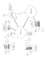
- data caching process 10 may reside on and may be executed by storage system 12 , which may be connected to network 14 (e.g., the Internet or a local area network).
- network 14 e.g., the Internet or a local area network.
- Examples of storage system 12 may include, but are not limited to: a Network Attached Storage (NAS) system, a Storage Area Network (SAN), a personal computer with a memory system, a server computer with a memory system, and a cloud-based device with a memory system.
- NAS Network Attached Storage
- SAN Storage Area Network
- a SAN may include one or more of a personal computer, a server computer, a series of server computers, a mini computer, a mainframe computer, a RAID device and a NAS system.
- the various components of storage system 12 may execute one or more operating systems, examples of which may include but are not limited to: Microsoft Windows XP ServerTM; Novell NetwareTM; Redhat LinuxTM, Unix, or a custom operating system, for example.
- Storage device 16 may include but is not limited to: a hard disk drive; a tape drive; an optical drive; a RAID device; a random access memory (RAM); a read-only memory (ROM); and all forms of flash memory storage devices.
- Network 14 may be connected to one or more secondary networks (e.g., network 18 ), examples of which may include but are not limited to: a local area network; a wide area network; or an intranet, for example.
- secondary networks e.g., network 18
- networks may include but are not limited to: a local area network; a wide area network; or an intranet, for example.
- data requests may be sent from client applications 22 , 24 , 26 , 28 to storage system 12 .
- Examples of data request 20 may include but are not limited to data write requests (i.e. a request that content be written to storage system 12 ) and data read requests (i.e. a request that content be read from storage system 12 ).
- the instruction sets and subroutines of client applications 22 , 24 , 26 , 28 which may be stored on storage devices 30 , 32 , 34 , 36 (respectively) coupled to client electronic devices 38 , 40 , 42 , 44 (respectively), may be executed by one or more processors (not shown) and one or more memory architectures (not shown) incorporated into client electronic devices 38 , 40 , 42 , 44 (respectively).
- Storage devices 30 , 32 , 34 , 36 may include but are not limited to: hard disk drives; tape drives; optical drives; RAID devices; random access memories (RAM); read-only memories (ROM), and all forms of flash memory storage devices.
- client electronic devices 38 , 40 , 42 , 44 may include, but are not limited to, personal computer 38 , laptop computer 40 , personal digital assistant 42 , notebook computer 44 , a server (not shown), a data-enabled, cellular telephone (not shown), and a dedicated network device (not shown).
- Client electronic devices 38 , 40 , 42 , 44 may each execute an operating system, examples of which may include but are not limited to Microsoft WindowsTM, Microsoft Windows CETM, Redhat LinuxTM, or a custom operating system.
- Users 46 , 48 , 50 , 52 may access storage system 12 directly through network 14 or through secondary network 18 . Further, storage system 12 may be connected to network 14 through secondary network 18 , as illustrated with link line 54 .
- the various client electronic devices may be directly or indirectly coupled to network 14 (or network 18 ).
- personal computer 38 is shown directly coupled to network 14 via a hardwired network connection.
- notebook computer 44 is shown directly coupled to network 18 via a hardwired network connection.
- Laptop computer 40 is shown wirelessly coupled to network 14 via wireless communication channel 56 established between laptop computer 40 and wireless access point (i.e., WAP) 58 , which is shown directly coupled to network 14 .
- WAP 58 may be, for example, an IEEE 802.11a, 802.11b, 802.11g, 802.11n, Wi-Fi, and/or Bluetooth device that is capable of establishing wireless communication channel 56 between laptop computer 40 and WAP 58 .
- Personal digital assistant 42 is shown wirelessly coupled to network 14 via wireless communication channel 60 established between personal digital assistant 42 and cellular network/bridge 62 , which is shown directly coupled to network 14 .
- IEEE 802.11x may use Ethernet protocol and carrier sense multiple access with collision avoidance (i.e., CSMA/CA) for path sharing.
- the various 802.11x specifications may use phase-shift keying (i.e., PSK) modulation or complementary code keying (i.e., CCK) modulation, for example.
- PSK phase-shift keying
- CCK complementary code keying
- Bluetooth is a telecommunications industry specification that allows e.g., mobile phones, computers, and personal digital assistants to be interconnected using a short-range wireless connection.
- client application 22 is going to be described for illustrative purposes. However, this is not intended to be a limitation of this disclosure, as other client applications (e.g., client applications 24 , 26 , 28 ) may be equally utilized.
- storage system 12 will be described as being a network-based storage system that includes a plurality of electro-mechanical backend storage devices.
- this is for illustrative purposes only and is not intended to be a limitation of this disclosure, as other configurations are possible and are considered to be within the scope of this disclosure.
- storage system 12 may be a personal computer that includes a single electro-mechanical storage device.
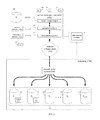
- storage system 12 may include a server computer/controller (e.g. server computer/controller 100 ), and a plurality of storage targets T 1-n (e.g. storage targets 102 , 104 , 106 , 108 ).
- Storage targets 102 , 104 , 106 , 108 may be configured to provide various levels of performance and/or high availability.
- one or more of storage targets 102 , 104 , 106 , 108 may be configured as a RAID 0 array, in which data is striped across storage targets. By striping data across a plurality of storage targets, improved performance may be realized. However, RAID 0 arrays do not provide a level of high availability.
- one or more of storage targets 102 , 104 , 106 , 108 may be configured as a RAID 1 array, in which data is mirrored between storage targets. By mirroring data between storage targets, a level of high availability is achieved as multiple copies of the data are stored within storage system 12 .
- storage targets 102 , 104 , 106 , 108 are discussed above as being configured in a RAID 0 or RAID 1 array, this is for illustrative purposes only and is not intended to be a limitation of this disclosure, as other configurations are possible.
- storage targets 102 , 104 , 106 , 108 may be configured as a RAID 3, RAID 4, RAID 5 or RAID 6 array.
- storage system 12 is shown to include four storage targets (e.g. storage targets 102 , 104 , 106 , 108 ), this is for illustrative purposes only and is not intended to be a limitation of this disclosure. Specifically, the actual number of storage targets may be increased or decreased depending upon e.g. the level of redundancy/performance/capacity required.
- Storage system 12 may also include one or more coded targets 110 .
- a coded target may be used to store coded data that may allow for the regeneration of data lost/corrupted on one or more of storage targets 102 , 104 , 106 , 108 .
- An example of such a coded target may include but is not limited to a hard disk drive that is used to store parity data within a RAID array.
- storage system 12 is shown to include one coded target (e.g., coded target 110 ), this is for illustrative purposes only and is not intended to be a limitation of this disclosure. Specifically, the actual number of coded targets may be increased or decreased depending upon e.g. the level of redundancy/performance/capacity required.
- Examples of storage targets 102 , 104 , 106 , 108 and coded target 110 may include one or more electro-mechanical hard disk drives, wherein a combination of storage targets 102 , 104 , 106 , 108 and coded target 110 may form non-volatile, electro-mechanical memory system 112 .
- storage system 12 may be a RAID device in which server computer/controller 100 is a RAID controller card and storage targets 102 , 104 , 106 , 108 and/or coded target 110 are individual “hot-swappable” hard disk drives.
- RAID device may include but is not limited to an NAS device.
- storage system 12 may be configured as a SAN, in which server computer/controller 100 may be e.g., a server computer and each of storage targets 102 , 104 , 106 , 108 and/or coded target 110 may be a RAID device and/or computer-based hard disk drive. Further still, one or more of storage targets 102 , 104 , 106 , 108 and/or coded target 110 may be a SAN.
- storage system 12 is configured as a SAN
- the various components of storage system 12 may be coupled using network infrastructure 114 , examples of which may include but are not limited to an Ethernet (e.g., Layer 2 or Layer 3) network, a fiber channel network, an InfiniBand network, or any other circuit switched/packet switched network.
- Ethernet e.g., Layer 2 or Layer 3
- Storage system 12 may execute all or a portion of data caching process 10 .
- the instruction sets and subroutines of data caching process 10 which may be stored on a storage device (e.g., storage device 16 ) coupled to server computer/controller 100 , may be executed by one or more processors (not shown) and one or more memory architectures (not shown) included within server computer/controller 100 .
- Storage device 16 may include but is not limited to: a hard disk drive; a tape drive; an optical drive; a RAID device; a random access memory (RAM); a read-only memory (ROM); and all forms of flash memory storage devices.
- various data requests may be generated. For example, these data requests may be sent from client applications 22 , 24 , 26 , 28 to storage system 12 . Additionally/alternatively and when server computer/controller 100 is configured as an application server, these data requests may be internally generated within server computer/controller 100 . Examples of data request 20 may include but are not limited to data write request 116 (i.e. a request that content 118 be written to storage system 12 ) and data read request 120 (i.e. a request that content 118 be read from storage system 12 ).
- Server computer/controller 100 may include input-output logic 122 (e.g., a network interface card or a Host Bus Adaptor (HBA)), processing logic 124 , and first cache system 126 .
- first cache system 126 may include but are not limited to a volatile, solid-state, cache memory system (e.g., a dynamic RAM cache memory system) and/or a non-volatile, solid-state, cache memory system (e.g., a flash-based, cache memory system).
- server computer/controller 100 During operation of server computer/controller 100 , content 118 to be written to storage system 12 may be received by input-output logic 122 (e.g. from network 14 and/or network 18 ) and processed by processing logic 124 . Additionally/alternatively and when server computer/controller 100 is configured as an application server, content 118 to be written to storage system 12 may be internally generated by server computer/controller 100 . As will be discussed below in greater detail, processing logic 124 may initially store content 118 within first cache system 126 .
- processing logic 124 may immediately write content 118 to second cache system 128 /non-volatile, electro-mechanical memory system 112 (if first cache system 126 is configured as a write-through cache) or may subsequently write content 118 to second cache system 128 /non-volatile, electro-mechanical memory system 112 (if first cache system 126 is configured as a write-back cache). Additionally and in certain configurations, processing logic 124 may calculate and store coded data on coded target 110 (included within non-volatile, electromechanical memory system 112 ) that may allow for the regeneration of data lost/corrupted on one or more of storage targets 102 , 104 , 106 , 108 .
- processing logic 124 may calculate and store coded data on coded target 110 .
- processing logic 124 may calculate and store coded data on coded target 110 .
- data array 130 may calculate and store coded data on coded target 110 .
- Examples of second cache system 128 may include but are not limited to a volatile, solid-state, cache memory system (e.g., a dynamic RAM cache memory system) and/or a non-volatile, solid-state, cache memory system (e.g., a flash-based, cache memory system).
- a volatile, solid-state, cache memory system e.g., a dynamic RAM cache memory system
- a non-volatile, solid-state, cache memory system e.g., a flash-based, cache memory system.
- first cache system 126 may be sized so that the number of times that data array 130 is accessed may be reduced. Accordingly, by sizing first cache system 126 so that first cache system 126 retains a quantity of data sufficient to satisfy a significant quantity of data requests (e.g., data request 20 ), the overall performance of storage system 12 may be enhanced. As will be described below in greater detail, first cache system 126 may be a content-aware cache system.
- second cache system 128 within data array 130 may be sized so that the number of times that non-volatile, electromechanical memory system 112 is accessed may be reduced. Accordingly, by sizing second cache system 128 so that second cache system 128 retains a quantity of data sufficient to satisfy a significant quantity of data requests (e.g., data request 20 ), the overall performance of storage system 12 may be enhanced. As will be described below in greater detail, second cache system 128 may be a content-aware cache system.
- the instruction sets and subroutines of data caching process 10 may be stored on storage device 16 included within storage system 12 , may be executed by one or more processors (not shown) and one or more memory architectures (not shown) included within storage system 12 . Accordingly, in addition to being executed on server computer/controller 100 , some or all of the instruction sets and subroutines of data caching process 10 may be executed by one or more processors (not shown) and one or more memory architectures (not shown) included within data array 130 .
- data request 20 (e.g. data read request 116 and/or data write request 120 ) may be processed by server computer/controller 100 to extract pertinent information concerning these data requests.
- write request 116 may include content 118 to be written to data array 130 .
- write request 116 may include a storage address 200 that defines the intended storage location within data array 130 at which content 118 is to be stored.
- storage address 200 may define a particular logical unit within data array 130 (e.g., a LUN or Logical Unit Number) and a particular storage address within that specific logical unit (e.g., an LBA or Logical Block Address) for storing content 118 .
- Read request 120 may include a storage address 202 that defines the storage location within data array 130 from which content is to be retrieved.
- storage address 202 may define a particular logical unit within data array 130 (e.g., a LUN or Logical Unit Number) and a particular storage address within that specific logical unit (e.g., an LBA or Logical Block Address) for retrieving the content sought from data array 130 .
- data caching process 10 may maintain content directory 250 , which may be used to locate various pieces of content within first cache system 126 .
- content directory 250 may include plurality of entries 252 , wherein each of these entries may identify: data array storage address 200 / 202 (e.g. a logical storage unit and a storage address at which a specific piece of previously-written content is located within data array 130 ); first cache address 254 (e.g., the location within first cache system 126 at which the specific piece of previously-written content is also located), and content identifier 256 for the specific piece of previously-written content.
- content directory 250 may identify the location of specific pieces of content included within first cache system 126 and their corresponding pieces of data within data array 130 , as well as a content identifier that uniquely identifies the specific piece of content.
- Content identifier 256 may be used in a content-aware caching system and may, specifically, be a mathematical representation of the specific piece of previously-written content that may allow e.g. server computer/controller 100 to quickly determine whether two pieces of previously-written content are identical, as identical pieces of content would have identical content identifiers.
- content identifier 256 may be a hash function (e.g., a cryptographic hash) of the previously-written content. Accordingly, through the use of a content-aware caching system, duplicate data entries within first cache system 126 and/or second cache system 128 may be quickly identified, avoided, and/or eliminated.
- a hash function is an algorithm/subroutine that maps large data sets to smaller data sets.
- the values returned by a hash function are typically called hash values, hash codes, hash sums, checksums or simply hashes.
- Hash functions are mostly used to accelerate table lookup or data comparison tasks such as e.g., finding items in a database and detecting duplicated or similar records in a large file.
- data caching process 10 may receive read request 120 on first cache system 126 , wherein read request 120 identifies previously-written content (as defined by storage address 202 ) included within data array 130 .
- client application 22 may generate read request 120 which, as discussed above, may define a particular logical unit within data array 130 (e.g., a LUN or Logical Unit Number) and a particular storage address within that specific logical unit (e.g., an LBA or Logical Block Address) for retrieving content 132 sought from data array 130 by client application 22 .
- a particular logical unit within data array 130 e.g., a LUN or Logical Unit Number
- a particular storage address within that specific logical unit e.g., an LBA or Logical Block Address
- read request 120 defines LUN0/LBA5 as the location of content 132 within data array 130 .
- data caching process 10 may compare the location of content 132 within data array 130 (namely LUN0/LBA5) with each of the plurality of entries 252 defined within content directory 250 to determine if a copy of content 132 is locally available (i.e., cached) within first cache system 126 . If LUN0/LBA5 was defined within content directory 250 (meaning that a local cached copy of content 132 is present/available within first cache system 126 ), that particular entry would also define a corresponding first cache address (e.g.
- first cache address 254 within first cache system 126 at which content 132 would be locally-available and retrievable from the first cache system 126 .
- data caching process 10 may need to obtain content 132 identified in read request 120 from data array 130 .
- LUN0/LBA5 is not defined within content directory 250 , a local cached copy of content 132 is not present/available within first cache system 126 and data caching process 10 will be need to obtain content 132 from data array 130 .
- data caching process 10 may store content 132 within first cache system 126 and may provide content 132 to client application 22 , thus satisfying read request 120 .
- content directory 250 may be amended by data caching process 10 to include an entry (e.g., entry 258 ) that defines the data array storage address 200 / 202 (e.g. LUN0/LBA5); first cache address 254 (e.g., 111110), and content identifier 256 (e.g., ablccba) for content 132 .
- data array 130 may include second cache system 128 . Accordingly, data caching process 10 may execute the above-described functionality with respect to second cache system 128 .
- data caching process 10 may receive write request 116 on first cache system 126 , wherein write request 116 identifies new content (e.g., content 118 ) to be written to data array 130 .
- client application 22 may generate write request 116 which, as discussed above, may define a particular logical unit within data array 130 (e.g., a LUN or Logical Unit Number) and a particular storage address within that specific logical unit (e.g., an LBA or Logical Block Address) for storing content 118 within data array 130 .
- a particular logical unit within data array 130 e.g., a LUN or Logical Unit Number
- a particular storage address within that specific logical unit e.g., an LBA or Logical Block Address
- data caching process 10 may immediately write content 118 to data array 130 (if first cache system 126 is configured as a write-through cache) or may subsequently write content 118 to data array 130 (if first cache system 126 is configured as a write-back cache).
- first cache system 126 in this example is configured as a write-through cache
- data caching process 10 may immediately write content 118 to LUN0/LBA0 within data array 130 (as defined within write request 116 ). Additionally, data caching process 10 may locally-store content 118 within first cache system 126 and may amend content directory 250 to include an entry (e.g., entry 260 ) that defines the data array storage address 200 / 202 (e.g. LUN0/LBA0); first cache address 254 (e.g., 001011), and content identifier 256 (e.g., acdfcla) for content 118 .
- entry e.g., entry 260 that defines the data array storage address 200 / 202 (e.g. LUN0/LBA0); first cache address 254 (e.g., 001011), and content identifier 256 (e.g., acdfcla) for content 118 .
- data array 130 may include second cache system 128 . Accordingly, data caching process 10 may execute the above described functionality with respect to second cache system 128 .
- content directory 250 may include a content identifier 256 that may be used in a content-aware caching system.
- a typical example of content identifier 256 may include but is not limited to a hash function of the content that content identifier 256 is associated with. Accordingly, through the use of content identifier 256 within a content-aware caching system, duplicate data entries within first cache system 126 and/or second cache system 128 may be quickly identified, avoided, and/or eliminated.
- data caching process 10 may generate content identifier 256 for content 118 .
- content identifier 256 generated for the content (i.e., content 118 ) identified within write request 116 may be a hash function (e.g., a cryptographic hash) of content 118 .
- write request 116 includes storage address 200 that defines the intended storage location for content 118 as LUN0/LBA0. Accordingly, upon receiving write request 116 , data caching process 10 may generate content identifier 256 for content 118 . Assume for illustrative purposes that data caching process 10 generates a hash of content 118 , resulting in the generation of content identifier 256 (namely hash value acdfcla).
- This newly-generated content identifier 256 (i.e. acdfcla) associated with content 118 may be compared to each of the other content identifiers (namely abalaby, alazchb, abalabz, alazcha) included within content directory 250 for first cache system 126 to determine if the newly-generated content identifier 256 (i.e. acdfcla) matches any of the other content identifiers (namely abalaby, alazchb, abalabz, alazcha) included within content directory 250 .
- each entry of the plurality of entries 252 included within content directory 250 is associated with a unique piece of content included within (in this example) first cache system 126 . Accordingly, each unique content identifier included within content directory 250 may be associated with a unique piece of content written to (in this example) first cache system 126 .
- data caching process 10 may write content 118 to (in this example) first cache system 126 and may provide a copy of content 118 to data array 130 for storage within data array 130 . Additionally, data caching process 10 may modify content directory 250 to include a new entry (i.e., entry 260 ) that defines the newly-generated content identifier (i.e. acdfcla), the location of content 118 within (in this example) first cache system 126 (i.e., 001011), and the location of content 118 within data array 130 (i.e., LUN0/LBA0).
- a content identifier i.e., abalaby, alazchb, abalabz, alazcha
- data caching process 10 If, when performing this comparison, data caching process 10 identified a content identifier within content directory 250 that matched the above-described, newly-generated content identifier (i.e. acdfcla), data caching process 10 would perform differently.
- a second write request (i.e., write request 116 ′) includes storage address 200 ′ that defines the intended storage location for content 118 ′ as LUN0/LBA2.
- data caching process 10 may generate content identifier 256 for content 118 ′.
- data caching process 10 generates a hash of content 118 ′, resulting in the generation of content identifier 256 (namely hash value alazcha).
- This newly-generated content identifier 256 (i.e. alazcha) associated with content 118 ′ may be compared to each of the other content identifiers (namely abalaby, alazchb, abalabz, alazcha) included within content directory 250 for (in this example) first cache system 126 to determine if the newly-generated content identifier 256 (i.e. alazcha) matches any of the other content identifiers (namely abalaby, alazchb, abalabz, alazcha) included within content directory 250 .
- data caching process 10 may perform a couple of functions.
- data caching process 10 may modify the entry (i.e., entry 262 ) within content directory 250 that is associated with the matching content identifier (i.e., alazcha) to include storage address 200 ′ that defines the intended storage location for content 118 ′ (i.e., LUN0/LBA2 within data array 130 ), thus generating modified entry 262 ′.
- modified entry 262 ′ identifies that the pieces of content that are currently stored at LUN4/LBA7 and LUN0/LBA2 within data array 130 are identical.
- a single piece of cached content located at first cache address 010111 within, in this example, first cache system 126 ) may be used as a local cached copy for both pieces of content stored on data array 130 .
- data array 130 may include second cache system 128 . Accordingly, data caching process 10 may execute the above-described content aware functionality with respect to second cache system 128 .
- first cache system 126 It may be desirable to compress the data stored within first cache system 126 and data array 130 to conserve storage space. For example, as the quantity of storage space available within first cache system 126 is limited, data caching process 10 may routinely monitor and process the data within first cache system 126 to compress 300 the data (if possible) to maximize the efficiency of first cache system 126 . Specifically, since data stored within first cache system 126 is stored within either volatile memory 150 or non-volatile memory 152 , this data may be quickly retrieved for processing (when compared to a disk-based storage systems).
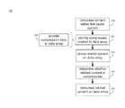
- data caching process 10 routinely compresses 300 data included within first cache system 126 , thus generating compressed content (e.g. compressed content 134 ). As each piece of content included within first cache system 126 has a corresponding piece of content within (in this example) data array 130 , data caching process 10 may identify 302 compressed content 134 to data array 130 .
- data caching process 10 may compress the data included within data array 130 in order to conserve storage space.
- the quantity of data included within data array 130 is often much greater (e.g., many orders of magnitude) than the quantity of data stored within first cache system 126 .
- the type of storage media included within data array 130 e.g. electromechanical hard disk drives
- the type of storage media included within first cache system 126 e.g. random access memory systems and flash memory systems. Accordingly, it may take a considerable amount of time to process and compress data included within data array 130 .
- data caching process 10 may prioritize the processing of content (e.g. related content 136 ) included within data array 130 that is related to compressed content (e.g. compressed content 134 ) included within first cache system 126 .
- content e.g. related content 136
- compressed content e.g. compressed content 134
- data caching process 10 may locate 304 related content (e.g. related content 136 ) within data array 130 . Locating the related content 136 within data array 130 may be accomplished through use of the above-described content directory 250 (to obtain the address of the content), which correlates content stored within first cache system 126 to content stored within storage array 130 . As discussed above and in this example, related content 136 located on data array 130 is the uncompressed version of compressed content 134 located on first cache system 126 .
- Data caching process 10 may process related content 136 to determine 306 whether related content 136 on data array 130 is compressible. For example, data caching process 10 may analyze related content 136 to determine the level at which related content 136 may be compressed within data array 130 . Alternatively/additionally, as related content 136 was already compressed on first cache system 126 (i.e. in the form of compressed content 134 ), data caching process 10 already knows the level of compressibility of related content 136 . Accordingly, when identifying 302 compressed content 134 to data array 130 , data caching process 10 may provide 308 the compression ratio of compressed content 134 to data array 130 . Data caching process 10 may subsequently use this compression ratio when determining 306 whether related content 136 on data array 130 is compressible.
- data caching process 10 determines a compression ratio for compressed content 134 . For example, if the original content was 1.00 MB in size and compressed content 134 is 200 kB in size, data caching process 10 may determine a compression ratio of 5:1 for compressed content 134 . Data caching process 10 may provide 308 this compression ratio to data array 130 .
- data caching process 10 may compare this compression ratio to a predefined threshold to determine whether related content 136 (stored on data array 130 ) is compressible. For example, assume for illustrative purposes that this predefined threshold is 3:1, wherein if the compression ratio is less than 3:1, related content 136 (stored on data array 130 ) would not be compressed 310 by data caching process 10 , as the computational expense of compressing related content 136 would not be offset by the space savings achieved. However, if the compression ratio is greater than or equal to 3:1, data caching process 10 would compress 310 related content 136 , as the space savings achieved on data array 130 would offset the computational expense of compressing related content 136 . Since the compression ratio of compressed content 134 is 5:1 (i.e., greater than or equal to 3:1), data caching process 10 may compress 310 related content 136 .
- data array 130 may include second cache system 128 . Accordingly, if data caching process 10 compresses 310 related content 136 on data array 130 and data array 130 also includes second cache system 128 , compressing 310 related content 136 may also include/may alternatively include compressing any cached copies of related content 136 stored on second cache system 128 .
- the present disclosure may be embodied as a method, system, or computer program product. Accordingly, the present disclosure may take the form of an entirely hardware embodiment, an entirely software embodiment (including firmware, resident software, micro-code, etc.) or an embodiment combining software and hardware aspects that may all generally be referred to herein as a “circuit,” “module” or “system.” Furthermore, the present disclosure may take the form of a computer program product on a computer-usable storage medium having computer-usable program code embodied in the medium.
- each block in the flowchart or block diagrams may represent a module, segment, or portion of code, which comprises one or more executable instructions for implementing the specified logical function(s).
- the functions noted in the block may occur out of the order noted in the figures. For example, two blocks shown in succession may, in fact, be executed substantially concurrently, or the blocks may sometimes be executed in the reverse order, depending upon the functionality involved.
Abstract
Description
Claims (24)
Priority Applications (1)
| Application Number | Priority Date | Filing Date | Title |
|---|---|---|---|
| US13/436,906 US8886883B1 (en) | 2012-03-31 | 2012-03-31 | System and method for improving cache performance |
Applications Claiming Priority (1)
| Application Number | Priority Date | Filing Date | Title |
|---|---|---|---|
| US13/436,906 US8886883B1 (en) | 2012-03-31 | 2012-03-31 | System and method for improving cache performance |
Publications (1)
| Publication Number | Publication Date |
|---|---|
| US8886883B1 true US8886883B1 (en) | 2014-11-11 |
Family
ID=51845920
Family Applications (1)
| Application Number | Title | Priority Date | Filing Date |
|---|---|---|---|
| US13/436,906 Active 2033-02-23 US8886883B1 (en) | 2012-03-31 | 2012-03-31 | System and method for improving cache performance |
Country Status (1)
| Country | Link |
|---|---|
| US (1) | US8886883B1 (en) |
Cited By (1)
| Publication number | Priority date | Publication date | Assignee | Title |
|---|---|---|---|---|
| US9727479B1 (en) * | 2014-09-30 | 2017-08-08 | EMC IP Holding Company LLC | Compressing portions of a buffer cache using an LRU queue |
Citations (23)
| Publication number | Priority date | Publication date | Assignee | Title |
|---|---|---|---|---|
| US4809065A (en) * | 1986-12-01 | 1989-02-28 | Kabushiki Kaisha Toshiba | Interactive system and related method for displaying data to produce a three-dimensional image of an object |
| US5710835A (en) * | 1995-11-14 | 1998-01-20 | The Regents Of The University Of California, Office Of Technology Transfer | Storage and retrieval of large digital images |
| US5875454A (en) * | 1996-07-24 | 1999-02-23 | International Business Machiness Corporation | Compressed data cache storage system |
| US6557083B1 (en) * | 2000-06-30 | 2003-04-29 | Intel Corporation | Memory system for multiple data types |
| US6567081B1 (en) * | 2000-01-21 | 2003-05-20 | Microsoft Corporation | Methods and arrangements for compressing image-based rendering (IBR) data using alignment and 3D wavelet transform techniques |
| US6580427B1 (en) * | 2000-06-30 | 2003-06-17 | Intel Corporation | Z-compression mechanism |
| US6724391B1 (en) * | 2000-06-30 | 2004-04-20 | Intel Corporation | Mechanism for implementing Z-compression transparently |
| US6735673B2 (en) * | 2002-01-10 | 2004-05-11 | Hewlett-Packard Development Company, L.P. | Apparatus and methods for cache line compression |
| US6857045B2 (en) * | 2002-01-25 | 2005-02-15 | International Business Machines Corporation | Method and system for updating data in a compressed read cache |
| US6920477B2 (en) * | 2001-04-06 | 2005-07-19 | President And Fellows Of Harvard College | Distributed, compressed Bloom filter Web cache server |
| US7243191B2 (en) * | 2004-08-31 | 2007-07-10 | Intel Corporation | Compressing data in a cache memory |
| US7412564B2 (en) * | 2004-11-05 | 2008-08-12 | Wisconsin Alumni Research Foundation | Adaptive cache compression system |
| US20100169382A1 (en) * | 2008-12-30 | 2010-07-01 | Gad Sheaffer | Metaphysical address space for holding lossy metadata in hardware |
| US7756345B2 (en) * | 2005-10-03 | 2010-07-13 | Canon Kabushiki Kaisha | Image compression data processing method, and image compression data processing apparatus |
| US7930483B2 (en) * | 2008-03-04 | 2011-04-19 | International Business Machines Corporation | Associativity implementation in a system with directly attached processor memory |
| US7984240B2 (en) * | 2008-03-04 | 2011-07-19 | International Business Machines Corporation | Memory compression implementation in a system with directly attached processor memory |
| US20120137061A1 (en) * | 2009-04-30 | 2012-05-31 | Velobit, Inc. | Pre-cache similarity-based delta compression for use in a data storage system |
| US8554745B2 (en) * | 2009-04-27 | 2013-10-08 | Netapp, Inc. | Nearstore compression of data in a storage system |
| US8595437B1 (en) * | 2008-11-21 | 2013-11-26 | Nvidia Corporation | Compression status bit cache with deterministic isochronous latency |
| US8700862B2 (en) * | 2008-12-03 | 2014-04-15 | Nvidia Corporation | Compression status bit cache and backing store |
| US8725939B1 (en) * | 2011-11-30 | 2014-05-13 | Emc Corporation | System and method for improving cache performance |
| US8738858B1 (en) * | 2011-11-30 | 2014-05-27 | Emc Corporation | System and method for improving cache performance |
| US8738857B1 (en) * | 2011-11-30 | 2014-05-27 | Emc Corporation | System and method for improving cache performance |
-
2012
- 2012-03-31 US US13/436,906 patent/US8886883B1/en active Active
Patent Citations (27)
| Publication number | Priority date | Publication date | Assignee | Title |
|---|---|---|---|---|
| US4809065A (en) * | 1986-12-01 | 1989-02-28 | Kabushiki Kaisha Toshiba | Interactive system and related method for displaying data to produce a three-dimensional image of an object |
| US5710835A (en) * | 1995-11-14 | 1998-01-20 | The Regents Of The University Of California, Office Of Technology Transfer | Storage and retrieval of large digital images |
| US5875454A (en) * | 1996-07-24 | 1999-02-23 | International Business Machiness Corporation | Compressed data cache storage system |
| US6567081B1 (en) * | 2000-01-21 | 2003-05-20 | Microsoft Corporation | Methods and arrangements for compressing image-based rendering (IBR) data using alignment and 3D wavelet transform techniques |
| US6557083B1 (en) * | 2000-06-30 | 2003-04-29 | Intel Corporation | Memory system for multiple data types |
| US6580427B1 (en) * | 2000-06-30 | 2003-06-17 | Intel Corporation | Z-compression mechanism |
| US6724391B1 (en) * | 2000-06-30 | 2004-04-20 | Intel Corporation | Mechanism for implementing Z-compression transparently |
| US6944720B2 (en) * | 2000-06-30 | 2005-09-13 | Intel Corporation | Memory system for multiple data types |
| US6920477B2 (en) * | 2001-04-06 | 2005-07-19 | President And Fellows Of Harvard College | Distributed, compressed Bloom filter Web cache server |
| US6735673B2 (en) * | 2002-01-10 | 2004-05-11 | Hewlett-Packard Development Company, L.P. | Apparatus and methods for cache line compression |
| US6857045B2 (en) * | 2002-01-25 | 2005-02-15 | International Business Machines Corporation | Method and system for updating data in a compressed read cache |
| US7243191B2 (en) * | 2004-08-31 | 2007-07-10 | Intel Corporation | Compressing data in a cache memory |
| US7412564B2 (en) * | 2004-11-05 | 2008-08-12 | Wisconsin Alumni Research Foundation | Adaptive cache compression system |
| US7756345B2 (en) * | 2005-10-03 | 2010-07-13 | Canon Kabushiki Kaisha | Image compression data processing method, and image compression data processing apparatus |
| US7984240B2 (en) * | 2008-03-04 | 2011-07-19 | International Business Machines Corporation | Memory compression implementation in a system with directly attached processor memory |
| US7930483B2 (en) * | 2008-03-04 | 2011-04-19 | International Business Machines Corporation | Associativity implementation in a system with directly attached processor memory |
| US8595437B1 (en) * | 2008-11-21 | 2013-11-26 | Nvidia Corporation | Compression status bit cache with deterministic isochronous latency |
| US8700862B2 (en) * | 2008-12-03 | 2014-04-15 | Nvidia Corporation | Compression status bit cache and backing store |
| US20100169382A1 (en) * | 2008-12-30 | 2010-07-01 | Gad Sheaffer | Metaphysical address space for holding lossy metadata in hardware |
| US8554745B2 (en) * | 2009-04-27 | 2013-10-08 | Netapp, Inc. | Nearstore compression of data in a storage system |
| US20120137061A1 (en) * | 2009-04-30 | 2012-05-31 | Velobit, Inc. | Pre-cache similarity-based delta compression for use in a data storage system |
| US20120137059A1 (en) * | 2009-04-30 | 2012-05-31 | Velobit, Inc. | Content locality-based caching in a data storage system |
| US20120144098A1 (en) * | 2009-04-30 | 2012-06-07 | Velobit, Inc. | Multiple locality-based caching in a data storage system |
| US20120144099A1 (en) * | 2009-04-30 | 2012-06-07 | Velobit, Inc. | Device driver deployment of similarity-based delta compression for use in a data storage system |
| US8725939B1 (en) * | 2011-11-30 | 2014-05-13 | Emc Corporation | System and method for improving cache performance |
| US8738858B1 (en) * | 2011-11-30 | 2014-05-27 | Emc Corporation | System and method for improving cache performance |
| US8738857B1 (en) * | 2011-11-30 | 2014-05-27 | Emc Corporation | System and method for improving cache performance |
Cited By (1)
| Publication number | Priority date | Publication date | Assignee | Title |
|---|---|---|---|---|
| US9727479B1 (en) * | 2014-09-30 | 2017-08-08 | EMC IP Holding Company LLC | Compressing portions of a buffer cache using an LRU queue |
Similar Documents
| Publication | Publication Date | Title |
|---|---|---|
| US9268711B1 (en) | System and method for improving cache performance | |
| US9405684B1 (en) | System and method for cache management | |
| US9134914B1 (en) | Deduplication | |
| US10324843B1 (en) | System and method for cache management | |
| US9268693B1 (en) | System and method for improving cache performance | |
| US9430368B1 (en) | System and method for caching data | |
| US9268696B1 (en) | System and method for improving cache performance | |
| US20140115252A1 (en) | Block storage-based data processing methods, apparatus, and systems | |
| US10268381B1 (en) | Tagging write requests to avoid data-log bypass and promote inline deduplication during copies | |
| US10614038B1 (en) | Inline deduplication of compressed data | |
| US8909886B1 (en) | System and method for improving cache performance upon detecting a migration event | |
| US20200210068A1 (en) | Cache management system and method | |
| US9336157B1 (en) | System and method for improving cache performance | |
| US8930626B1 (en) | Cache management system and method | |
| US8554954B1 (en) | System and method for improving cache performance | |
| US9286219B1 (en) | System and method for cache management | |
| US8990615B1 (en) | System and method for cache management | |
| US8886883B1 (en) | System and method for improving cache performance | |
| US10817206B2 (en) | System and method for managing metadata redirections | |
| US9208098B1 (en) | System and method for improving cache performance | |
| US9098204B1 (en) | System and method for improving cache performance | |
| US9128854B1 (en) | System and method for data prediction | |
| US8966190B1 (en) | System and method for assigning control of a logical unit number | |
| US9424175B1 (en) | System and method for improving cache performance | |
| US10101940B1 (en) | Data retrieval system and method |
Legal Events
| Date | Code | Title | Description |
|---|---|---|---|
| AS | Assignment |
Owner name: EMC CORPORATION, MASSACHUSETTS Free format text: ASSIGNMENT OF ASSIGNORS INTEREST;ASSIGNORS:MARSHAK, MARIK;DON, ARIEH;VEPRINSKY, ALEXANDR "ALEX";REEL/FRAME:029480/0105 Effective date: 20121203 |
|
| AS | Assignment |
Owner name: EMC CORPORATION, MASSACHUSETTS Free format text: ASSIGNMENT OF ASSIGNORS INTEREST;ASSIGNOR:DERBEKO, PHILIP;REEL/FRAME:033325/0691 Effective date: 20140709 |
|
| STCF | Information on status: patent grant |
Free format text: PATENTED CASE |
|
| AS | Assignment |
Owner name: THE BANK OF NEW YORK MELLON TRUST COMPANY, N.A., AS NOTES COLLATERAL AGENT, TEXAS Free format text: SECURITY AGREEMENT;ASSIGNORS:ASAP SOFTWARE EXPRESS, INC.;AVENTAIL LLC;CREDANT TECHNOLOGIES, INC.;AND OTHERS;REEL/FRAME:040136/0001 Effective date: 20160907 Owner name: CREDIT SUISSE AG, CAYMAN ISLANDS BRANCH, AS COLLATERAL AGENT, NORTH CAROLINA Free format text: SECURITY AGREEMENT;ASSIGNORS:ASAP SOFTWARE EXPRESS, INC.;AVENTAIL LLC;CREDANT TECHNOLOGIES, INC.;AND OTHERS;REEL/FRAME:040134/0001 Effective date: 20160907 Owner name: CREDIT SUISSE AG, CAYMAN ISLANDS BRANCH, AS COLLAT Free format text: SECURITY AGREEMENT;ASSIGNORS:ASAP SOFTWARE EXPRESS, INC.;AVENTAIL LLC;CREDANT TECHNOLOGIES, INC.;AND OTHERS;REEL/FRAME:040134/0001 Effective date: 20160907 Owner name: THE BANK OF NEW YORK MELLON TRUST COMPANY, N.A., A Free format text: SECURITY AGREEMENT;ASSIGNORS:ASAP SOFTWARE EXPRESS, INC.;AVENTAIL LLC;CREDANT TECHNOLOGIES, INC.;AND OTHERS;REEL/FRAME:040136/0001 Effective date: 20160907 |
|
| AS | Assignment |
Owner name: EMC IP HOLDING COMPANY LLC, MASSACHUSETTS Free format text: ASSIGNMENT OF ASSIGNORS INTEREST;ASSIGNOR:EMC CORPORATION;REEL/FRAME:040203/0001 Effective date: 20160906 |
|
| MAFP | Maintenance fee payment |
Free format text: PAYMENT OF MAINTENANCE FEE, 4TH YEAR, LARGE ENTITY (ORIGINAL EVENT CODE: M1551) Year of fee payment: 4 |
|
| AS | Assignment |
Owner name: THE BANK OF NEW YORK MELLON TRUST COMPANY, N.A., T Free format text: SECURITY AGREEMENT;ASSIGNORS:CREDANT TECHNOLOGIES, INC.;DELL INTERNATIONAL L.L.C.;DELL MARKETING L.P.;AND OTHERS;REEL/FRAME:049452/0223 Effective date: 20190320 Owner name: THE BANK OF NEW YORK MELLON TRUST COMPANY, N.A., TEXAS Free format text: SECURITY AGREEMENT;ASSIGNORS:CREDANT TECHNOLOGIES, INC.;DELL INTERNATIONAL L.L.C.;DELL MARKETING L.P.;AND OTHERS;REEL/FRAME:049452/0223 Effective date: 20190320 |
|
| AS | Assignment |
Owner name: THE BANK OF NEW YORK MELLON TRUST COMPANY, N.A., TEXAS Free format text: SECURITY AGREEMENT;ASSIGNORS:CREDANT TECHNOLOGIES INC.;DELL INTERNATIONAL L.L.C.;DELL MARKETING L.P.;AND OTHERS;REEL/FRAME:053546/0001 Effective date: 20200409 |
|
| AS | Assignment |
Owner name: WYSE TECHNOLOGY L.L.C., CALIFORNIA Free format text: RELEASE BY SECURED PARTY;ASSIGNOR:CREDIT SUISSE AG, CAYMAN ISLANDS BRANCH;REEL/FRAME:058216/0001 Effective date: 20211101 Owner name: SCALEIO LLC, MASSACHUSETTS Free format text: RELEASE BY SECURED PARTY;ASSIGNOR:CREDIT SUISSE AG, CAYMAN ISLANDS BRANCH;REEL/FRAME:058216/0001 Effective date: 20211101 Owner name: MOZY, INC., WASHINGTON Free format text: RELEASE BY SECURED PARTY;ASSIGNOR:CREDIT SUISSE AG, CAYMAN ISLANDS BRANCH;REEL/FRAME:058216/0001 Effective date: 20211101 Owner name: MAGINATICS LLC, CALIFORNIA Free format text: RELEASE BY SECURED PARTY;ASSIGNOR:CREDIT SUISSE AG, CAYMAN ISLANDS BRANCH;REEL/FRAME:058216/0001 Effective date: 20211101 Owner name: FORCE10 NETWORKS, INC., CALIFORNIA Free format text: RELEASE BY SECURED PARTY;ASSIGNOR:CREDIT SUISSE AG, CAYMAN ISLANDS BRANCH;REEL/FRAME:058216/0001 Effective date: 20211101 Owner name: EMC IP HOLDING COMPANY LLC, TEXAS Free format text: RELEASE BY SECURED PARTY;ASSIGNOR:CREDIT SUISSE AG, CAYMAN ISLANDS BRANCH;REEL/FRAME:058216/0001 Effective date: 20211101 Owner name: EMC CORPORATION, MASSACHUSETTS Free format text: RELEASE BY SECURED PARTY;ASSIGNOR:CREDIT SUISSE AG, CAYMAN ISLANDS BRANCH;REEL/FRAME:058216/0001 Effective date: 20211101 Owner name: DELL SYSTEMS CORPORATION, TEXAS Free format text: RELEASE BY SECURED PARTY;ASSIGNOR:CREDIT SUISSE AG, CAYMAN ISLANDS BRANCH;REEL/FRAME:058216/0001 Effective date: 20211101 Owner name: DELL SOFTWARE INC., CALIFORNIA Free format text: RELEASE BY SECURED PARTY;ASSIGNOR:CREDIT SUISSE AG, CAYMAN ISLANDS BRANCH;REEL/FRAME:058216/0001 Effective date: 20211101 Owner name: DELL PRODUCTS L.P., TEXAS Free format text: RELEASE BY SECURED PARTY;ASSIGNOR:CREDIT SUISSE AG, CAYMAN ISLANDS BRANCH;REEL/FRAME:058216/0001 Effective date: 20211101 Owner name: DELL MARKETING L.P., TEXAS Free format text: RELEASE BY SECURED PARTY;ASSIGNOR:CREDIT SUISSE AG, CAYMAN ISLANDS BRANCH;REEL/FRAME:058216/0001 Effective date: 20211101 Owner name: DELL INTERNATIONAL, L.L.C., TEXAS Free format text: RELEASE BY SECURED PARTY;ASSIGNOR:CREDIT SUISSE AG, CAYMAN ISLANDS BRANCH;REEL/FRAME:058216/0001 Effective date: 20211101 Owner name: DELL USA L.P., TEXAS Free format text: RELEASE BY SECURED PARTY;ASSIGNOR:CREDIT SUISSE AG, CAYMAN ISLANDS BRANCH;REEL/FRAME:058216/0001 Effective date: 20211101 Owner name: CREDANT TECHNOLOGIES, INC., TEXAS Free format text: RELEASE BY SECURED PARTY;ASSIGNOR:CREDIT SUISSE AG, CAYMAN ISLANDS BRANCH;REEL/FRAME:058216/0001 Effective date: 20211101 Owner name: AVENTAIL LLC, CALIFORNIA Free format text: RELEASE BY SECURED PARTY;ASSIGNOR:CREDIT SUISSE AG, CAYMAN ISLANDS BRANCH;REEL/FRAME:058216/0001 Effective date: 20211101 Owner name: ASAP SOFTWARE EXPRESS, INC., ILLINOIS Free format text: RELEASE BY SECURED PARTY;ASSIGNOR:CREDIT SUISSE AG, CAYMAN ISLANDS BRANCH;REEL/FRAME:058216/0001 Effective date: 20211101 |
|
| MAFP | Maintenance fee payment |
Free format text: PAYMENT OF MAINTENANCE FEE, 8TH YEAR, LARGE ENTITY (ORIGINAL EVENT CODE: M1552); ENTITY STATUS OF PATENT OWNER: LARGE ENTITY Year of fee payment: 8 |
|
| AS | Assignment |
Owner name: SCALEIO LLC, MASSACHUSETTS Free format text: RELEASE OF SECURITY INTEREST IN PATENTS PREVIOUSLY RECORDED AT REEL/FRAME (040136/0001);ASSIGNOR:THE BANK OF NEW YORK MELLON TRUST COMPANY, N.A., AS NOTES COLLATERAL AGENT;REEL/FRAME:061324/0001 Effective date: 20220329 Owner name: EMC IP HOLDING COMPANY LLC (ON BEHALF OF ITSELF AND AS SUCCESSOR-IN-INTEREST TO MOZY, INC.), TEXAS Free format text: RELEASE OF SECURITY INTEREST IN PATENTS PREVIOUSLY RECORDED AT REEL/FRAME (040136/0001);ASSIGNOR:THE BANK OF NEW YORK MELLON TRUST COMPANY, N.A., AS NOTES COLLATERAL AGENT;REEL/FRAME:061324/0001 Effective date: 20220329 Owner name: EMC CORPORATION (ON BEHALF OF ITSELF AND AS SUCCESSOR-IN-INTEREST TO MAGINATICS LLC), MASSACHUSETTS Free format text: RELEASE OF SECURITY INTEREST IN PATENTS PREVIOUSLY RECORDED AT REEL/FRAME (040136/0001);ASSIGNOR:THE BANK OF NEW YORK MELLON TRUST COMPANY, N.A., AS NOTES COLLATERAL AGENT;REEL/FRAME:061324/0001 Effective date: 20220329 Owner name: DELL MARKETING CORPORATION (SUCCESSOR-IN-INTEREST TO FORCE10 NETWORKS, INC. AND WYSE TECHNOLOGY L.L.C.), TEXAS Free format text: RELEASE OF SECURITY INTEREST IN PATENTS PREVIOUSLY RECORDED AT REEL/FRAME (040136/0001);ASSIGNOR:THE BANK OF NEW YORK MELLON TRUST COMPANY, N.A., AS NOTES COLLATERAL AGENT;REEL/FRAME:061324/0001 Effective date: 20220329 Owner name: DELL PRODUCTS L.P., TEXAS Free format text: RELEASE OF SECURITY INTEREST IN PATENTS PREVIOUSLY RECORDED AT REEL/FRAME (040136/0001);ASSIGNOR:THE BANK OF NEW YORK MELLON TRUST COMPANY, N.A., AS NOTES COLLATERAL AGENT;REEL/FRAME:061324/0001 Effective date: 20220329 Owner name: DELL INTERNATIONAL L.L.C., TEXAS Free format text: RELEASE OF SECURITY INTEREST IN PATENTS PREVIOUSLY RECORDED AT REEL/FRAME (040136/0001);ASSIGNOR:THE BANK OF NEW YORK MELLON TRUST COMPANY, N.A., AS NOTES COLLATERAL AGENT;REEL/FRAME:061324/0001 Effective date: 20220329 Owner name: DELL USA L.P., TEXAS Free format text: RELEASE OF SECURITY INTEREST IN PATENTS PREVIOUSLY RECORDED AT REEL/FRAME (040136/0001);ASSIGNOR:THE BANK OF NEW YORK MELLON TRUST COMPANY, N.A., AS NOTES COLLATERAL AGENT;REEL/FRAME:061324/0001 Effective date: 20220329 Owner name: DELL MARKETING L.P. (ON BEHALF OF ITSELF AND AS SUCCESSOR-IN-INTEREST TO CREDANT TECHNOLOGIES, INC.), TEXAS Free format text: RELEASE OF SECURITY INTEREST IN PATENTS PREVIOUSLY RECORDED AT REEL/FRAME (040136/0001);ASSIGNOR:THE BANK OF NEW YORK MELLON TRUST COMPANY, N.A., AS NOTES COLLATERAL AGENT;REEL/FRAME:061324/0001 Effective date: 20220329 Owner name: DELL MARKETING CORPORATION (SUCCESSOR-IN-INTEREST TO ASAP SOFTWARE EXPRESS, INC.), TEXAS Free format text: RELEASE OF SECURITY INTEREST IN PATENTS PREVIOUSLY RECORDED AT REEL/FRAME (040136/0001);ASSIGNOR:THE BANK OF NEW YORK MELLON TRUST COMPANY, N.A., AS NOTES COLLATERAL AGENT;REEL/FRAME:061324/0001 Effective date: 20220329 |
|
| AS | Assignment |
Owner name: SCALEIO LLC, MASSACHUSETTS Free format text: RELEASE OF SECURITY INTEREST IN PATENTS PREVIOUSLY RECORDED AT REEL/FRAME (045455/0001);ASSIGNOR:THE BANK OF NEW YORK MELLON TRUST COMPANY, N.A., AS NOTES COLLATERAL AGENT;REEL/FRAME:061753/0001 Effective date: 20220329 Owner name: EMC IP HOLDING COMPANY LLC (ON BEHALF OF ITSELF AND AS SUCCESSOR-IN-INTEREST TO MOZY, INC.), TEXAS Free format text: RELEASE OF SECURITY INTEREST IN PATENTS PREVIOUSLY RECORDED AT REEL/FRAME (045455/0001);ASSIGNOR:THE BANK OF NEW YORK MELLON TRUST COMPANY, N.A., AS NOTES COLLATERAL AGENT;REEL/FRAME:061753/0001 Effective date: 20220329 Owner name: EMC CORPORATION (ON BEHALF OF ITSELF AND AS SUCCESSOR-IN-INTEREST TO MAGINATICS LLC), MASSACHUSETTS Free format text: RELEASE OF SECURITY INTEREST IN PATENTS PREVIOUSLY RECORDED AT REEL/FRAME (045455/0001);ASSIGNOR:THE BANK OF NEW YORK MELLON TRUST COMPANY, N.A., AS NOTES COLLATERAL AGENT;REEL/FRAME:061753/0001 Effective date: 20220329 Owner name: DELL MARKETING CORPORATION (SUCCESSOR-IN-INTEREST TO FORCE10 NETWORKS, INC. AND WYSE TECHNOLOGY L.L.C.), TEXAS Free format text: RELEASE OF SECURITY INTEREST IN PATENTS PREVIOUSLY RECORDED AT REEL/FRAME (045455/0001);ASSIGNOR:THE BANK OF NEW YORK MELLON TRUST COMPANY, N.A., AS NOTES COLLATERAL AGENT;REEL/FRAME:061753/0001 Effective date: 20220329 Owner name: DELL PRODUCTS L.P., TEXAS Free format text: RELEASE OF SECURITY INTEREST IN PATENTS PREVIOUSLY RECORDED AT REEL/FRAME (045455/0001);ASSIGNOR:THE BANK OF NEW YORK MELLON TRUST COMPANY, N.A., AS NOTES COLLATERAL AGENT;REEL/FRAME:061753/0001 Effective date: 20220329 Owner name: DELL INTERNATIONAL L.L.C., TEXAS Free format text: RELEASE OF SECURITY INTEREST IN PATENTS PREVIOUSLY RECORDED AT REEL/FRAME (045455/0001);ASSIGNOR:THE BANK OF NEW YORK MELLON TRUST COMPANY, N.A., AS NOTES COLLATERAL AGENT;REEL/FRAME:061753/0001 Effective date: 20220329 Owner name: DELL USA L.P., TEXAS Free format text: RELEASE OF SECURITY INTEREST IN PATENTS PREVIOUSLY RECORDED AT REEL/FRAME (045455/0001);ASSIGNOR:THE BANK OF NEW YORK MELLON TRUST COMPANY, N.A., AS NOTES COLLATERAL AGENT;REEL/FRAME:061753/0001 Effective date: 20220329 Owner name: DELL MARKETING L.P. (ON BEHALF OF ITSELF AND AS SUCCESSOR-IN-INTEREST TO CREDANT TECHNOLOGIES, INC.), TEXAS Free format text: RELEASE OF SECURITY INTEREST IN PATENTS PREVIOUSLY RECORDED AT REEL/FRAME (045455/0001);ASSIGNOR:THE BANK OF NEW YORK MELLON TRUST COMPANY, N.A., AS NOTES COLLATERAL AGENT;REEL/FRAME:061753/0001 Effective date: 20220329 Owner name: DELL MARKETING CORPORATION (SUCCESSOR-IN-INTEREST TO ASAP SOFTWARE EXPRESS, INC.), TEXAS Free format text: RELEASE OF SECURITY INTEREST IN PATENTS PREVIOUSLY RECORDED AT REEL/FRAME (045455/0001);ASSIGNOR:THE BANK OF NEW YORK MELLON TRUST COMPANY, N.A., AS NOTES COLLATERAL AGENT;REEL/FRAME:061753/0001 Effective date: 20220329 |