US8888756B2 - Plug for container - Google Patents
Plug for container Download PDFInfo
- Publication number
- US8888756B2 US8888756B2 US13/138,803 US201013138803A US8888756B2 US 8888756 B2 US8888756 B2 US 8888756B2 US 201013138803 A US201013138803 A US 201013138803A US 8888756 B2 US8888756 B2 US 8888756B2
- Authority
- US
- United States
- Prior art keywords
- split piece
- plug
- fitting portion
- partition wall
- flange portion
- Prior art date
- Legal status (The legal status is an assumption and is not a legal conclusion. Google has not performed a legal analysis and makes no representation as to the accuracy of the status listed.)
- Expired - Fee Related, expires
Links
Images


Classifications
-
- A—HUMAN NECESSITIES
- A61—MEDICAL OR VETERINARY SCIENCE; HYGIENE
- A61J—CONTAINERS SPECIALLY ADAPTED FOR MEDICAL OR PHARMACEUTICAL PURPOSES; DEVICES OR METHODS SPECIALLY ADAPTED FOR BRINGING PHARMACEUTICAL PRODUCTS INTO PARTICULAR PHYSICAL OR ADMINISTERING FORMS; DEVICES FOR ADMINISTERING FOOD OR MEDICINES ORALLY; BABY COMFORTERS; DEVICES FOR RECEIVING SPITTLE
- A61J1/00—Containers specially adapted for medical or pharmaceutical purposes
- A61J1/14—Details; Accessories therefor
- A61J1/1412—Containers with closing means, e.g. caps
-
- A—HUMAN NECESSITIES
- A61—MEDICAL OR VETERINARY SCIENCE; HYGIENE
- A61J—CONTAINERS SPECIALLY ADAPTED FOR MEDICAL OR PHARMACEUTICAL PURPOSES; DEVICES OR METHODS SPECIALLY ADAPTED FOR BRINGING PHARMACEUTICAL PRODUCTS INTO PARTICULAR PHYSICAL OR ADMINISTERING FORMS; DEVICES FOR ADMINISTERING FOOD OR MEDICINES ORALLY; BABY COMFORTERS; DEVICES FOR RECEIVING SPITTLE
- A61J1/00—Containers specially adapted for medical or pharmaceutical purposes
- A61J1/14—Details; Accessories therefor
- A61J1/1406—Septums, pierceable membranes
-
- A—HUMAN NECESSITIES
- A61—MEDICAL OR VETERINARY SCIENCE; HYGIENE
- A61J—CONTAINERS SPECIALLY ADAPTED FOR MEDICAL OR PHARMACEUTICAL PURPOSES; DEVICES OR METHODS SPECIALLY ADAPTED FOR BRINGING PHARMACEUTICAL PRODUCTS INTO PARTICULAR PHYSICAL OR ADMINISTERING FORMS; DEVICES FOR ADMINISTERING FOOD OR MEDICINES ORALLY; BABY COMFORTERS; DEVICES FOR RECEIVING SPITTLE
- A61J1/00—Containers specially adapted for medical or pharmaceutical purposes
- A61J1/14—Details; Accessories therefor
- A61J1/1475—Inlet or outlet ports
-
- B—PERFORMING OPERATIONS; TRANSPORTING
- B65—CONVEYING; PACKING; STORING; HANDLING THIN OR FILAMENTARY MATERIAL
- B65D—CONTAINERS FOR STORAGE OR TRANSPORT OF ARTICLES OR MATERIALS, e.g. BAGS, BARRELS, BOTTLES, BOXES, CANS, CARTONS, CRATES, DRUMS, JARS, TANKS, HOPPERS, FORWARDING CONTAINERS; ACCESSORIES, CLOSURES, OR FITTINGS THEREFOR; PACKAGING ELEMENTS; PACKAGES
- B65D51/00—Closures not otherwise provided for
- B65D51/002—Closures to be pierced by an extracting-device for the contents and fixed on the container by separate retaining means
Definitions
- the present invention relates to a plug used for a container for containing liquid such as a drug solution.
- an anti-cancer drug used for treating cancer is used by being prepared in an infusion solution, there is a risk that a healthcare professional who handles the anti-cancer drug would be exposed thereto in administering the anti-cancer drug and discarding thereafter a container which contained the anti-cancer drug.
- Many anti-cancer drugs have cytotoxicity since these drugs inhibit cell division not only of cancer cells but of normal cells, and are known to have mutagenicity, teratogenicity, and carcinogenicity.
- carcinogenicity it has been confirmed that anti-cancer drugs such as cyclophosphamide, azathioprine, and the like have a carcinogenic action with respect to the human body.
- the risk to the healthcare professional who handles the anti-cancer drug is determined not only by the strength of the toxicity of the drug, but by the body intake amount and the intake period due to the aspiration of the aerosolized drug through the respiratory tract during handling, the attachment of droplets of a drug solution to the skin, the oral intake or the like. Accordingly, since a healthcare professional who handles the anti-cancer drug for a long time is likely to take in the drug for a long time even if the amount is very small, there is a demand for improving the sealing function realized by a plug of a container such as a vial that contains a drug solution of an anti-cancer drug.
- a technique is used.
- a preparation operation such as mixing of drug solutions is performed in a cabinet in which a closed operation space can be specified, whereby the drug solution is prevented from diffusing outside the cabinet, and the risk that the healthcare professional may be exposed to the drug is reduced.
- the scattering range of the drug solution is unexpectedly wide and a medium to which the drug solution has been attached may be carried out of the cabinet, thereby contaminating the surrounding environment. Consequently, it has been proved that a healthcare professional cannot avoid exposure to the drug even if a cabinet is used.
- a plug for a container is disclosed as a stopper for an injection in Patent Literature 1, for example.
- FIG. 9 is a cross-sectional view showing a plug 4 of a container according to another related art.
- a container 1 includes a container body 2 that contains a drug solution and a plug 4 that seals an opening portion 3 of the container body 2 .
- the plug 4 includes a flange portion 6 that is placed on a flange 5 at the body side formed in the opening portion 3 of the container body 2 , a cylindrical peripheral wall 7 having one end connected to an inner peripheral portion of the flange portion 6 at a right angle, an end wall 8 that is integrally formed in the other end of the peripheral wall 7 , and a partition wall 9 that is integrally formed inside a radial direction of the peripheral wall 7 from a middle portion thereof.
- a closed space 10 is formed between the end wall 8 and the partition wall 9 .
- Patent Literature 1 Japanese Unexamined Patent Publication JP-A 6-335514 (1994)
- the plug 4 has a problem in that when inserted injection needle 11 is pulled out, at the time when the tip of the injection needle 11 is taken out from the inner space of the container body 2 , passes through the partition wall 9 , and is pulled toward the closed wall 10 side, the drug solution that leaks inside the closed space 10 from a crack that is formed when the injection needle 11 is inserted into the partition wall 9 cannot be reliably prevented from leaking outside from a crack formed in the end wall 8 .
- An object of the invention is to provide a plug for a container that has a simple configuration, is inexpensive, and can reliably prevent the leakage of liquid when an inserted needle is pulled.
- the invention provides a plug for a container including a first split piece formed of a flexible and resilient material, the first split piece having a cylindrical fitting portion to be mounted on and fitted to an opening portion of a container body containing liquid, the cylindrical fitting portion provided with an opening formed on one end side thereof and an opening formed on the other end side thereof, an end wall which blocks the opening formed on the one end side, and a first flange portion extending outwardly in a radial direction of the fitting portion from the other end thereof; and
- a second split piece formed of a flexible and resilient material, the second split piece having a partition wall which blocks the opening formed on the other end side and forms a closed space between the end wall and the partition wall and a second flange portion extending outwardly in a radial direction of the partition wall therefrom and being disposed so as to be placed on the first flange portion.
- an absorber formed of a liquid-absorbing material is contained in the closed space.
- the end wall of the first split piece and the partition wall of the second split piece are separated from each other at an interval which is equal to or longer than a length in an axial direction of an end surface of a tip portion of an injection needle that is inserted through the partition wall.
- the liquid is a drug solution.
- a water-absorptive polymer is contained in the closed space.
- a plug mounted on an opening portion of a container body is configured with a first split piece and a second split piece.
- the first and second split pieces are formed of a flexible and resilient material. While the split pieces are mounted on the opening portion of the container body, the fitting portion of the first split piece is fitted into the opening portion of the container body, the second flange portion is placed on the first flange portion, and the closed space is formed between the end wall and the partition wall. Accordingly, it is possible to separately sterilize the whole surface by separately producing the first and second split pieces and to form a clean closed space.
- first and second split pieces While the first and second split pieces are combined and mounted on the opening portion of the container body, the outer peripheral surface of the fitting portion comes into contact with the inner peripheral surface of the opening portion of the container body, the first flange portion comes into contact with the end surface of the opening portion of the container body, and the second flange portion of the second split piece is placed on the first flange portion. Since the first and second split pieces are formed of a flexible and resilient material, the first flange portion tightly adheres to the end surface of the opening portion of the container body, and the second flange portion tightly adheres to the first flange portion, whereby high air-tightness and liquid-tightness can be accomplished.
- first and second flange portions are provided while being placed on the opening portion of the container body. Consequently, the end wall formed while being connected to an in-plane direction of the first flange portion and the partition wall formed while being connected to an in-plane direction of the second flange portion more easily undergo elastic deformation compared to the first and second flange portions.
- the end wall and the partition wall undergo the elastic deformation toward the outside by a sliding friction force between the injection needle and the end wall and a sliding friction force between the injection needle and the partition wall.
- the partition wall undergoes the elastic deformation to the outside due to the sliding friction force caused by pulling of the injection needle. Therefore, a negative pressure is created in the closed space, and the negative pressure acts in the gap between the crack of the partition wall and the injection needle.
- the first and second split pieces can be easily realized by a well-known molding technique such as compression molding that uses a metal mold, it is possible to produce a leakage-free plug at a low cost.
- the liquid that leaks inside the closed space is absorbed into the absorber. Therefore, it is possible to more reliably prevent the liquid from leaking between the crack of the partition wall and the injection needle.
- the closed space includes a region having an interval equal to or larger than the length in the axial direction of the end surface of the tip portion of the injection needle, a period is not created in which the tip portion of the injection needle is partially present in both the end wall and the partition wall at the same time. Consequently, when the injection needle is taken out from the end wall and the partition wall, at the time when the wedge-like tip portion of the injection needle passes through the end wall, a right cylinder-like portion that is closer to the base portion than to the tip portion of the injection needle passes through the partition wall, and the partition wall uniformly comes into contact with almost the entire outer peripheral surface of the injection needle. Accordingly, a state is prevented in which the crack formed in the end wall and the crack formed in the partition wall are not incompletely closed at the same time, and it is possible to more reliably prevent the leakage of liquid.
- the leakage of liquid can be suppressed with a high sealing performance by the plug. Therefore, when the liquid is a drug solution such as an anti-cancer drug, the handler is prevented from being exposed to the drug solution, and it is possible to significantly improve the safety with respect to the exposure to the drug solution at a low cost.
- a drug solution such as an anti-cancer drug
- a water-absorptive polymer is contained in the closed space. Accordingly, when the injection needle is taken out from the end wall, the liquid that leaks inside the closed space can be polymerized by the water-absorptive polymer and captured in the closed space as sol-like or gel-like fluid. Consequently, it is possible to more reliably prevent the leakage of liquid.
- FIG. 1 is a partially enlarged cross-sectional view showing a vial sealed by a plug 20 for a container according to an embodiment of the invention
- FIG. 2 is an enlarged cross-sectional view of a first split piece 29 ;
- FIG. 3 is an enlarged cross-sectional view of a second split piece 33 ;
- FIG. 4 is a graph showing measurement results of a leaked amount measured by the inventors
- FIG. 5 is a partial cross-sectional view showing a vial 21 a sealed by a plug for a container according to another embodiment of the invention.
- FIG. 6 is a partially enlarged cross-sectional view showing a vial 21 b sealed by a plug 20 b of a container according to still another embodiment of the invention.
- FIG. 7 is a partially enlarged cross-sectional view showing an infusion bag 121 sealed by a plug 20 c of a container according to still another embodiment of the invention.
- FIG. 8 is a front view of the plug 20 c taken when FIG. 7 is seen from below;
- FIG. 9 is a cross-sectional view showing a plug 4 of a container according to another related art.
- FIG. 10A is a front view of a plug 100 used as a comparative example.
- FIG. 10B is a cross-sectional view of the plug 100 .
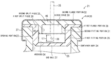
- FIG. 1 is a partially enlarged cross-sectional view showing a vial 21 sealed by a plug 20 for a container according to an embodiment of the invention.
- the plug 20 used for the vial 21 as a container includes a first split piece 29 which has a cylindrical first fitting portion 26 that is mounted on an opening portion 23 of a bottomed cylinder-like container body 24 containing liquid 22 and fitted to an opening portion space 25 surrounded by the opening portion 23 , an end wall 27 that blocks one end facing the opening portion space 25 of the first fitting portion 26 , and a first flange portion 28 extending outwardly in a radial direction of the first fitting portion 26 from the other end thereof; a second split piece 33 which has a second fitting portion 31 with an inverted-U-shaped cross-section that forms a closed space 30 between the end wall 27 and the second fitting portion 31 by being fitted to the first fitting portion 26 of the first split piece 29 , and a second flange portion 32 that extends outwardly in a radial direction of the second fitting portion
- the first and second split pieces 29 and 33 are formed of a flexible and resilient material.
- the flexible and resilient material is mainly a thermosetting elastomer formed of synthetic rubber such as butyl rubber, silicone rubber, isoprene rubber, and butadiene rubber, and natural rubber, and realized by so-called vulcanized rubber material.
- the material may be a thermoplastic elastomer and a styrene-based elastomer such as an olefin-based resin including polypropylene, polystyrene, and the like.
- the hardness of the first split piece 29 is selected from 1 to 90, and preferably from 10 to 80 (JIS-K6301).
- the hardness of at least a needle-inserting portion of the second split piece 33 is selected from 1 to 90, and preferably 10 to 80 (JIS-K6301).
- the hardness of the first and second split pieces 29 and 33 in this range is preferable in the respect that an injection needle 35 is easily inserted, formability becomes excellent in production, the injection needle 35 is inserted with high adhesiveness, and desired air-tightness and liquid-tightness are obtained.
- an axial direction length of a portion where an end surface 36 of a wedge-like tip portion of the injection needle 35 that is inserted through a partition wall 46 is L 1
- the end wall 27 of the first split piece 29 and the partition wall 46 of the second split piece 33 are separated from each other at an interval equal to or larger than the axial direction length L 1 .
- the second fitting portion 31 includes a cylindrical fitting cylinder portion 45 and the partition wall 46 that extends inwardly in a radial direction of the fitting cylinder portion 45 from one end in an axial direction thereof.
- the partition wall 46 is formed to be approximately parallel with the end wall 27 of the first split piece 29 , in a state in which the second split piece 33 is fitted to the first split piece 29 , and the absorber 34 is contained in the closed space 30 between the partition wall 46 and the end wall 27 .
- the absorber 34 is formed of a foamed synthetic resin having interconnected cells, for example. As the foamed synthetic resin having interconnected cells, sponge formed of a synthetic resin with chemical resistance may be used.
- the liquid is a drug such as an anti-cancer drug having cytotoxicity, for example.
- This type of drug is prepared in an infusion solution, and when administered to a patient, and discarded, a healthcare professional who handles the vial 21 is at a risk of being exposed to the anti-cancer drug. Therefore, the opening portion 23 of the container body 24 is sealed by the plug 20 of the embodiment.
- the use of this type of plug 20 makes it possible to accomplish high air-tightness and liquid-tightness in any state of before and during the insertion of the injection needle 35 and during and after the removal of the injection needle 35 .
- FIG. 2 is an enlarged cross-sectional view of the first split piece 29 .
- the first split piece 29 is formed of a molded material made of thermosetting synthetic resin.
- FIG. 3 is an enlarged cross-sectional view of the second split piece 33 .
- the second split piece 33 is formed of a molded material made of a thermosetting synthetic resin.
- FIG. 4 is a graph showing measurement results of a leaked amount measured by the inventors.
- the inventors carried out the following test on Comparative example 1 and Examples 1 and 2.
- Type of drug solution 100 mM sodium cinnamate aqueous solution
- a measurement method of the amount of the leaked drug solution is as follows.
- Cinnamic acid included in the drug solution soaked into the filter paper was eluted in a constant volume of purified water.
- the elute was analyzed with UV-detection capillary electrophoresis, and the amount of the cinnamic acid included in the leaked liquid was measured by absolute quantitation, thereby calculating the volume of the leaked liquid.
- the measurement conditions were capillary: fused silica (an internal diameter of 50 ⁇ m, a length of 62 cm), migration liquid: 50 mM boric acid buffer (pH 10.5), voltage: 30 kV, detection wavelength: 270 nm, and measurement temperature: 25° C.
- Hardness of first split piece 29 hardness of 45
- Hardness of second split piece 33 hardness of 45
- the average of the leaked amount was calculated and then divided by 9.
- the standard deviation thereof the average of the leaked amount was subtracted from the leaked amount of each operation, and the resultant was squared, thereby calculating the sum of squared deviation.
- variance was calculated, and the standard deviation was calculated by extracting the square root of the variance.
- FIG. 10A is a front view of a plug 100 used as a comparative example
- FIG. 10B is a cross-sectional view of the plug 100
- the plug 100 is configured by a flange portion 101 that is placed on a flange 5 at the body side formed in an opening portion 3 of a container body 2 , and a cylindrical peripheral wall 102 that includes one end connected to the inner peripheral portion of a flange portion 101 at a right angle and extends toward the container body.
- Example 1 Amount of leaked liquid ( ⁇ l) 19.8 0.0 2.0 30.0 0.0 0.0 14.8 0.0 1.8 8.5 0.0 0.5 11.8 3.1 0.2 22.3 5.8 0.0 9.3 0.0 0.0 13.1 0.0 0.0 20.5 0.0 0.8 Average 16.7 1.0 0.6 Standard deviation 7.0 2.1 0.8
- the second fitting portion 31 of the second split piece 33 is fitted to the first fitting portion 26 of the first split piece 29 , and the closed space 30 is formed between the end wall 27 of the first split piece 29 and the partition wall 46 of the second split piece 33 . Therefore, by separating the first and second split pieces 29 and 33 , it is possible to open the closed space 30 , sterilize the inside of the closed space 30 , and to remove foreign substances in the closed space 30 .
- This type of plug 20 may be mounted on the opening portion 23 of the container body 24 in a state in which the first fitting portion 26 of the first split piece 29 is fitted to the second fitting portion 31 of the second split piece 33 so as to combine the first split piece 29 with the second split piece 33 .
- the second fitting portion 31 of the second split piece 33 may be fitted to the first fitting portion 26 of the first split piece 29 .
- the outer peripheral surface of the first fitting portion 26 tightly adheres to the inner peripheral surface of the opening portion 23 of the container body 24 , whereby the high air-tightness and liquid-tightness can be accomplished.
- the second split piece 33 includes the second flange portion 32 , the first flange portion 28 is pressed on the opening portion 23 of the container body 24 by the second flange portion 32 , so the first flange portion 28 tightly adheres to the end surface of the opening portion 23 of the container body 24 . This also makes it possible to accomplish the high air-tightness and liquid-tightness.
- the end wall 27 formed while being connected to an in-plate direction of the first flange portion 28 and the partition wall 46 formed while being connected to an in-plate direction of the second flange portion 32 are tightly held on the opening portion 23 by the protector cap 37 . Therefore, the end wall 27 and the partition wall 46 more easily undergo elastic deformation compared to the first and second flange portions 28 and 32 , and when the inserted injection needle 35 is taken out from the end wall 27 and the partition wall 46 , the end wall 27 and the partition wall 46 undergo elastic deformation outwardly (toward an upper side in FIG. 1 ) due to the sliding friction force between the injection needle 35 and the end wall 27 and the sliding friction force between the inserted injection needle 35 and the partition wall 46 .
- the first and second split pieces 29 and 33 can be easily realized by a well-known method such as compression molding that uses a metal mold, it is possible to produce the leakage-free plug 20 at a low cost.
- the absorber 34 formed of a liquid-absorbing material is contained in the closed space 30 . Therefore, when the injection needle 35 is inserted into the container body 24 through the partition wall 46 and the end wall 27 , and when the injection needle 35 that has been inserted into the container body 24 is pulled, even if the drug solution in the container body 24 leaks inside the closed space 30 through the gap between the inner surface of the crack that is formed due to the insertion of the injection needle 35 into the end wall 27 and the injection needle 35 , the leaked liquid is absorbed into the absorber 34 . Consequently, it is possible to more reliably prevent the liquid from leaking outside through the gap between the inner surface of the crack that is formed due to the insertion of the injection needle 35 into the partition wall 46 and the injection needle 35 .
- the closed space 30 is configured to have an interval equal to or larger than the axial direction length L 1 of the end surface 36 of the tip portion of the injection needle 35 . Consequently, a period is not created in which the tip portion of the injection needle 35 is partially present in both the end wall 27 and the partition wall portion 46 at the same time. Accordingly, while the injection needle 35 is taken out from the end wall 27 and the partition wall 46 , when the wedge-like tip portion of the injection needle 35 passes through the end wall 27 , a right cylindrical portion that is closer to the base portion than to the tip portion of the injection needle 35 passes through the partition wall 46 , and the partition wall portion 46 uniformly contacts almost the entire outer peripheral surface of the injection needle 35 . Accordingly, a state is prevented in which the crack formed in the end wall 27 and the crack formed in the partition wall 46 are not incompletely closed at the same time, and it is possible to more reliably prevent the leakage of liquid.
- the leakage of liquid can be suppressed with a high sealing performance by the plug 20 described above. Therefore, when the liquid is a drug solution such as an anti-cancer drug with high volatility, the handler of the vial 21 is prevented from being exposed to the drug solution, and it is possible to further improve the safety with respect to the exposure to the drug solution at a low cost.
- a drug solution such as an anti-cancer drug with high volatility
- FIG. 5 is a partial cross-sectional view showing a vial 21 a sealed by a plug 20 a for a container according to another embodiment of the invention.
- the portions corresponding to those of the embodiment described above are denoted by the same reference numerals.
- the plug 20 a for a container of the present embodiment has a configuration in which a third split piece 50 is interposed as an intermediate split piece between the first split piece 29 and the second split piece 33 , the third split piece 50 is sandwiched between the first split piece 29 and the second split piece 33 on the same axis, and the first to third split pieces 29 , 33 , and 50 are fastened to the opening portion 23 of the container body 24 by a protector cap 60 .
- the third split piece 50 includes a third fitting portion 51 with an inverted-U-shaped cross-section that is fitted to the first fitting portion 26 of the first split piece 29 and forms a first closed space 30 a between the end wall 27 and the third fitting portion 51 , and a cylindrical peripheral wall 52 that extends outwardly in a radial direction of the third fitting portion 51 therefrom and protrudes to one side in an axial direction thereof from the third fitting portion 51 .
- the third fitting portion 51 includes a cylindrical fitting cylinder portion 53 and a partition wall 54 formed extending inwardly in a radial direction of the fitting cylinder portion 53 from one end in an axial direction thereof.
- the first closed space 30 a is formed between the end wall 27 of the first split piece 29 and the partition wall 54 of the third split piece 50
- a second closed space 30 b is formed between the partition wall 54 of the third split piece 50 and the partition wall 46 of the second split piece 33 .
- the respective closed spaces 30 a and 30 b have an interval equal to or larger than the axial direction length L 1 of the end surface 36 of the tip portion of the inserted injection needle 35 , and contain absorbers 34 a and 34 b respectively that are the same as the absorber 34 of the embodiment described above.
- the first and second closed spaces 30 a and 30 b are formed, and the absorbers 34 a and 34 b are contained in the closed spaces 30 a and 30 b , respectively. Accordingly, it is possible to more reliably prevent the leakage of the drug solution caused when injection needle is taken out from the end wall 27 and the respective partition wall portions 46 and 54 .
- FIG. 6 is a partially enlarged cross-sectional view showing a vial 21 b sealed by a plug 20 b of a container according to still another embodiment of the invention. Portions corresponding to those of the embodiment described above are denoted by the same reference numerals, and the repeated description thereof is omitted. Though similar to the plug 20 of the embodiment in FIG. 1 , the plug 20 b of the present embodiment is different from the plug 20 in that the second fitting portion 31 described above is not provided in the second split piece 33 .
- This type of plug 20 b is formed of a circular plate-like molded body in which the partition wall 46 is integrally formed while being connected to an in-plane direction of the second flange portion 32 .
- the first flange portion 28 and the second flange portion 32 are tightly held on the opening portion 23 by the protector cap 37 , in a state in which the second flange portion 32 is placed on the first flange portion 28 .
- the partition wall 46 is caused to flexibly undergo elastic deformation by the sliding friction force caused by the pulling of the injection needle 35 , a negative pressure is created in the closed space 30 accordingly, and the negative pressure is introduced to the gap between the crack of the partition wall 46 and the injection needle 35 , whereby it is possible to reliably prevent the liquid from leaking inside the closed space 30 .
- FIG. 7 is a partially enlarged cross-sectional view showing an infusion bag 121 sealed by a plug 20 c of a container according to still another embodiment of the invention.
- FIG. 8 is a front view of the plug 20 c taken when FIG. 7 is seen from below. Portions corresponding to those of the embodiment described above are denoted by the same reference numerals, and the repeated description thereof is omitted.
- the plug 20 c of the present embodiment is mounted on an opening portion 71 of a pouch-like bag 70 made of polypropylene as a container body by a cap 72 .
- the cap 72 includes a cylindrical portion 73 with an approximately right cylindrical shape, and an engagement claw portion 74 that is connected to the inner peripheral portion of one end of the cylindrical portion 73 and protrudes toward the other end of the cylindrical portion 73 .
- the plug 20 c includes the first split piece 29 in which the end wall 27 is formed in one end of the first fitting portion 26 , and the first flange portion 28 is integrally formed extending outwardly in the radial direction of the end wall 27 therefrom; and the second split piece 33 in which an engagement projection portion 75 , which is engaged between the engagement claw portion 74 and one end portion of the cylindrical portion 73 by being fixed therebetween, is formed in the outer peripheral portion thereof.
- circular ring-like protuberant portions 77 a , 77 b , and 77 c that indicate an insertion position of the injection needle 35 are axisymmetrically formed.
- the closed space 30 is formed between the end wall 27 of the first split piece 29 and the partition wall portion 46 of the second split piece 33 , and the absorber 34 is contained in the closed space 30 .
- the first flange portion 28 and the engagement projection portion 75 are tightly held between the end surface of the opening portion 71 and the engagement claw portion 74 of the cap 72 , whereby the air-tightness and the liquid-tightness are accomplished.
- infusion bag 121 it is also possible to reliably prevent the liquid from leaking when the injection needle 35 that has been inserted in the respective protuberant portions 77 a , 77 b , and 77 c of the partition wall 46 is taken out, similarly to the embodiment described above.
- a configuration may be employed in which the closed spaces 30 ; 30 a and 30 b are not provided with the absorbers 34 ; 34 a and 34 b .
- a water-absorptive polymer may be contained in the closed space instead of the absorbers 34 ; 34 a and 34 b , and the water-absorptive polymer may be contained in the closed space together with the absorbers 34 ; 34 a and 34 b .
- the water-absorptive polymer include sodium polyacrylate.
- the absorbers 34 ; 34 a and 34 b are contained in the closed spaces 30 ; 30 a and 30 b , or if only the water-absorptive polymer is contained, or if both the absorbers 34 ; 34 a and 34 b and the water-absorptive polymer are contained, it is possible to capture the liquid that permeates the closed spaces 30 ; 30 a and 30 b , and to more reliably prevent the liquid from leaking outside from the crack of the partition wall.
Abstract
Description
| TABLE 1 | |||
| Comparative | |||
| example 1 | Example 1 | Example 2 | |
| Amount of leaked liquid (μl) | 19.8 | 0.0 | 2.0 |
| 30.0 | 0.0 | 0.0 | |
| 14.8 | 0.0 | 1.8 | |
| 8.5 | 0.0 | 0.5 | |
| 11.8 | 3.1 | 0.2 | |
| 22.3 | 5.8 | 0.0 | |
| 9.3 | 0.0 | 0.0 | |
| 13.1 | 0.0 | 0.0 | |
| 20.5 | 0.0 | 0.8 | |
| Average | 16.7 | 1.0 | 0.6 |
| Standard deviation | 7.0 | 2.1 | 0.8 |
Claims (6)
Applications Claiming Priority (4)
| Application Number | Priority Date | Filing Date | Title |
|---|---|---|---|
| JP2009083682 | 2009-03-30 | ||
| JP2009083682 | 2009-03-30 | ||
| JPP2009-083682 | 2009-03-30 | ||
| PCT/JP2010/055466 WO2010113823A1 (en) | 2009-03-30 | 2010-03-26 | Container plug |
Publications (2)
| Publication Number | Publication Date |
|---|---|
| US20130085466A1 US20130085466A1 (en) | 2013-04-04 |
| US8888756B2 true US8888756B2 (en) | 2014-11-18 |
Family
ID=42828114
Family Applications (1)
| Application Number | Title | Priority Date | Filing Date |
|---|---|---|---|
| US13/138,803 Expired - Fee Related US8888756B2 (en) | 2009-03-30 | 2010-03-26 | Plug for container |
Country Status (4)
| Country | Link |
|---|---|
| US (1) | US8888756B2 (en) |
| EP (1) | EP2415687B1 (en) |
| JP (2) | JP5399477B2 (en) |
| WO (1) | WO2010113823A1 (en) |
Cited By (2)
| Publication number | Priority date | Publication date | Assignee | Title |
|---|---|---|---|---|
| US11013865B2 (en) | 2013-10-15 | 2021-05-25 | Becton Dickinson France | Tip cap assembly for closing an injection system |
| US20230365306A1 (en) * | 2022-05-16 | 2023-11-16 | NEXA3D Inc. | System and method for dispensing fluid from a container with a stacked arrangement of cross-slit valves |
Families Citing this family (10)
| Publication number | Priority date | Publication date | Assignee | Title |
|---|---|---|---|---|
| WO2013061537A1 (en) * | 2011-10-26 | 2013-05-02 | パナソニック株式会社 | Drug solution transfer and injection method, and drug solution transfer and injection device |
| JP2014050647A (en) * | 2012-09-10 | 2014-03-20 | Kinki Univ | Injection needle for anticancer agent administration, production method therefor, and anticancer agent administration kit including injection needle |
| WO2014149854A1 (en) * | 2013-03-19 | 2014-09-25 | Walterspiel Juan Nepomuc | Devices and methods to reduce contamination of fluid collected from a patient |
| WO2015079547A1 (en) * | 2013-11-29 | 2015-06-04 | 株式会社日立産機システム | Replenishment container and inkjet recording device comprising same |
| JP6139046B2 (en) * | 2015-04-30 | 2017-05-31 | 大塚テクノ株式会社 | Drug container lid cover |
| JP2017197197A (en) * | 2016-04-25 | 2017-11-02 | 株式会社日立産機システム | Replenishing container and ink jet recording device having the same |
| US11324664B2 (en) | 2017-03-24 | 2022-05-10 | Carefusion 303, Inc. | Dry disconnect cartridge and dual lumen needle for automatic drug compounder |
| US20210237912A1 (en) * | 2018-06-04 | 2021-08-05 | Pathway, Llc | Vacuum-controlled liquid delivery systems and methods for drawing a liquid into a syringe |
| WO2020090724A1 (en) * | 2018-11-01 | 2020-05-07 | ニプロ株式会社 | Compound container, liquid supply method and liquid collection method |
| CN114906476B (en) * | 2022-05-12 | 2023-03-24 | 四川先通原子医药科技有限公司 | Rubber cover body, container and application thereof |
Citations (14)
| Publication number | Priority date | Publication date | Assignee | Title |
|---|---|---|---|---|
| US2186888A (en) * | 1938-08-06 | 1940-01-09 | Burroughs Wellcome Co | Antiseptic bottle closure |
| US3017050A (en) * | 1955-01-10 | 1962-01-16 | Sr Courtland H Barr | Blood sample collection apparatus |
| US4152269A (en) * | 1977-02-01 | 1979-05-01 | Warner-Lambert Company | Collection and separation device |
| US4187893A (en) * | 1978-07-19 | 1980-02-12 | Abbott Laboratories | Combined additive and administration port for a container |
| US4226333A (en) * | 1976-03-04 | 1980-10-07 | Becton, Dickinson And Company | Cannula pierceable self-sealing closure |
| US4243150A (en) * | 1978-01-23 | 1981-01-06 | Siemens Aktiengesellschaft | Bottle seal |
| US4582207A (en) | 1985-04-02 | 1986-04-15 | Bristol-Myers Company | Safety reservoir snap on overcap for parenteral drug container |
| JPS61247459A (en) | 1985-04-25 | 1986-11-04 | テルモ株式会社 | Plug body for medical container |
| JPS62160941A (en) | 1986-01-10 | 1987-07-16 | Nissan Motor Co Ltd | Seat frame |
| JPH06335514A (en) | 1993-05-28 | 1994-12-06 | Shiotani M S Kk | Stopper for injection |
| JPH0713346A (en) | 1993-06-23 | 1995-01-17 | Canon Inc | Manufacture of electrophotographic photoreceptor |
| JP2001289743A (en) | 2000-04-11 | 2001-10-19 | Mitsubishi Heavy Ind Ltd | Pneumatic jug for carrying sample |
| JP2002345925A (en) | 2001-05-28 | 2002-12-03 | Ohtsu Tire & Rubber Co Ltd :The | Laminated rubber product for medical purpose and method of manufacturing for the same |
| JP2004269038A (en) | 2003-01-16 | 2004-09-30 | Nippon Shooter Ltd | Specimen transfer jug |
Family Cites Families (2)
| Publication number | Priority date | Publication date | Assignee | Title |
|---|---|---|---|---|
| JPS519544Y2 (en) * | 1971-03-12 | 1976-03-13 | ||
| JPS62160941U (en) * | 1986-03-31 | 1987-10-13 |
-
2010
- 2010-03-26 WO PCT/JP2010/055466 patent/WO2010113823A1/en active Application Filing
- 2010-03-26 JP JP2011507164A patent/JP5399477B2/en active Active
- 2010-03-26 US US13/138,803 patent/US8888756B2/en not_active Expired - Fee Related
- 2010-03-26 EP EP10758595.2A patent/EP2415687B1/en not_active Not-in-force
-
2013
- 2013-09-18 JP JP2013193568A patent/JP5716064B2/en not_active Expired - Fee Related
Patent Citations (16)
| Publication number | Priority date | Publication date | Assignee | Title |
|---|---|---|---|---|
| US2186888A (en) * | 1938-08-06 | 1940-01-09 | Burroughs Wellcome Co | Antiseptic bottle closure |
| US3017050A (en) * | 1955-01-10 | 1962-01-16 | Sr Courtland H Barr | Blood sample collection apparatus |
| US4226333A (en) * | 1976-03-04 | 1980-10-07 | Becton, Dickinson And Company | Cannula pierceable self-sealing closure |
| US4152269A (en) * | 1977-02-01 | 1979-05-01 | Warner-Lambert Company | Collection and separation device |
| US4243150A (en) * | 1978-01-23 | 1981-01-06 | Siemens Aktiengesellschaft | Bottle seal |
| US4187893A (en) * | 1978-07-19 | 1980-02-12 | Abbott Laboratories | Combined additive and administration port for a container |
| US4582207A (en) | 1985-04-02 | 1986-04-15 | Bristol-Myers Company | Safety reservoir snap on overcap for parenteral drug container |
| JPS61228865A (en) | 1985-04-02 | 1986-10-13 | ブリストル―マイアーズ スクイブ コムパニー | Overcap with safe sump inlay for parenteral drug container |
| JPS61247459A (en) | 1985-04-25 | 1986-11-04 | テルモ株式会社 | Plug body for medical container |
| US4682703A (en) | 1985-04-25 | 1987-07-28 | Terumo Kabushiki Kaisha | Stopper for medical container |
| JPS62160941A (en) | 1986-01-10 | 1987-07-16 | Nissan Motor Co Ltd | Seat frame |
| JPH06335514A (en) | 1993-05-28 | 1994-12-06 | Shiotani M S Kk | Stopper for injection |
| JPH0713346A (en) | 1993-06-23 | 1995-01-17 | Canon Inc | Manufacture of electrophotographic photoreceptor |
| JP2001289743A (en) | 2000-04-11 | 2001-10-19 | Mitsubishi Heavy Ind Ltd | Pneumatic jug for carrying sample |
| JP2002345925A (en) | 2001-05-28 | 2002-12-03 | Ohtsu Tire & Rubber Co Ltd :The | Laminated rubber product for medical purpose and method of manufacturing for the same |
| JP2004269038A (en) | 2003-01-16 | 2004-09-30 | Nippon Shooter Ltd | Specimen transfer jug |
Non-Patent Citations (4)
| Title |
|---|
| European Office Action dated Aug. 28, 2013. |
| Japanese Decision of Refusal for corresponding Japanese Application No. 2011-507164 (full translation provided). |
| Japanese Office Action dated Apr. 2, 2013 for corresponding Japanese Application No. 2011-507164 (full translation provided). |
| PCT International Preliminary Report on Patentability dated Nov. 24, 2011 for Application No. PCT/JP2010/055466 and English translation thereof. |
Cited By (2)
| Publication number | Priority date | Publication date | Assignee | Title |
|---|---|---|---|---|
| US11013865B2 (en) | 2013-10-15 | 2021-05-25 | Becton Dickinson France | Tip cap assembly for closing an injection system |
| US20230365306A1 (en) * | 2022-05-16 | 2023-11-16 | NEXA3D Inc. | System and method for dispensing fluid from a container with a stacked arrangement of cross-slit valves |
Also Published As
| Publication number | Publication date |
|---|---|
| JP2014037275A (en) | 2014-02-27 |
| JP5399477B2 (en) | 2014-01-29 |
| WO2010113823A1 (en) | 2010-10-07 |
| JP5716064B2 (en) | 2015-05-13 |
| US20130085466A1 (en) | 2013-04-04 |
| JPWO2010113823A1 (en) | 2012-12-13 |
| EP2415687A1 (en) | 2012-02-08 |
| EP2415687A4 (en) | 2012-12-19 |
| EP2415687B1 (en) | 2015-09-02 |
Similar Documents
| Publication | Publication Date | Title |
|---|---|---|
| US8888756B2 (en) | Plug for container | |
| US4366912A (en) | Rubber closure device for vials | |
| JP3380705B2 (en) | Sealed rubber stopper for syringe and container | |
| CA2016734C (en) | Syringe assembly | |
| WO2014162347A1 (en) | Connector and transfusion set | |
| JPH10165500A (en) | Prefilled syringe | |
| US5061252A (en) | Syringe assembly | |
| BR112015001962B1 (en) | FLUID RESERVOIR AND FLUID PRESSURE MEASUREMENT UNIT TO MEASURE A FLUID PRESSURE IN THE SAME | |
| CN111671444B (en) | Integrated safety tube seal with membrane element | |
| CN211402158U (en) | Reagent strip device of dual biological safety protection | |
| JP2016536053A (en) | Needle protection device | |
| JP4717924B2 (en) | Method for preventing loss of active ingredient of radiopharmaceutical in prefilled syringe | |
| US20170203052A1 (en) | Syringe assembly, pre-filled syringe, seal cap for sheath with puncture needle, and syringe assembly package | |
| JP4635175B2 (en) | Highly sealed syringe filled with chemical liquid, gasket, and manufacturing method of syringe filled with chemical liquid | |
| JP2009022371A (en) | Medical cap and its manufacturing method | |
| JPH0725953Y2 (en) | Syringe stopper | |
| JPH0546456Y2 (en) | ||
| CN111447963B (en) | Front end cap | |
| CN107106786B (en) | Assembly for syringe, prefilled syringe, seal cap for outer tube with puncture needle, and assembly package for syringe | |
| CN219167110U (en) | Blood transfusion bag | |
| CN209153711U (en) | A kind of separation gel vacuum blood collection tube sealing device | |
| JPH105311A (en) | Medical resealable member and plug for medical container | |
| JPH06327771A (en) | Syringe packed with liquid chemicals | |
| JP2016042902A (en) | Gasket for syringe | |
| CN104434520A (en) | Polypropylene infusion port combined plug for plastic infusion bag |
Legal Events
| Date | Code | Title | Description |
|---|---|---|---|
| AS | Assignment |
Owner name: SHINAGAWA CO., LTD., JAPAN Free format text: ASSIGNMENT OF ASSIGNORS INTEREST;ASSIGNORS:ISHIWATA, SHUNJI;TAGA, ATSUSHI;FUJITA, HIDEKI;AND OTHERS;REEL/FRAME:027281/0826 Effective date: 20111003 Owner name: KINKI UNIVERSITY, JAPAN Free format text: ASSIGNMENT OF ASSIGNORS INTEREST;ASSIGNORS:ISHIWATA, SHUNJI;TAGA, ATSUSHI;FUJITA, HIDEKI;AND OTHERS;REEL/FRAME:027281/0826 Effective date: 20111003 |
|
| AS | Assignment |
Owner name: KINKI UNIVERSITY, JAPAN Free format text: ASSIGNMENT OF ASSIGNORS INTEREST;ASSIGNORS:ISHIWATA, SHUNJI;TAGA, ATSUSHI;FUJITA, HIDEKI;AND OTHERS;REEL/FRAME:027333/0107 Effective date: 20111003 Owner name: SHINAGAWA CO., LTD., JAPAN Free format text: ASSIGNMENT OF ASSIGNORS INTEREST;ASSIGNORS:ISHIWATA, SHUNJI;TAGA, ATSUSHI;FUJITA, HIDEKI;AND OTHERS;REEL/FRAME:027333/0107 Effective date: 20111003 |
|
| AS | Assignment |
Owner name: GTO LTD., JAPAN Free format text: TRANSFER OF ASSIGNMENT;ASSIGNOR:SHINAGAWA CO., LTD.;REEL/FRAME:029926/0494 Effective date: 20130131 |
|
| STCF | Information on status: patent grant |
Free format text: PATENTED CASE |
|
| CC | Certificate of correction | ||
| MAFP | Maintenance fee payment |
Free format text: PAYMENT OF MAINTENANCE FEE, 4TH YEAR, LARGE ENTITY (ORIGINAL EVENT CODE: M1551) Year of fee payment: 4 |
|
| FEPP | Fee payment procedure |
Free format text: MAINTENANCE FEE REMINDER MAILED (ORIGINAL EVENT CODE: REM.); ENTITY STATUS OF PATENT OWNER: LARGE ENTITY |
|
| LAPS | Lapse for failure to pay maintenance fees |
Free format text: PATENT EXPIRED FOR FAILURE TO PAY MAINTENANCE FEES (ORIGINAL EVENT CODE: EXP.); ENTITY STATUS OF PATENT OWNER: LARGE ENTITY |
|
| STCH | Information on status: patent discontinuation |
Free format text: PATENT EXPIRED DUE TO NONPAYMENT OF MAINTENANCE FEES UNDER 37 CFR 1.362 |
|
| FP | Lapsed due to failure to pay maintenance fee |
Effective date: 20221118 |